1
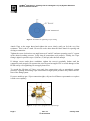
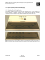
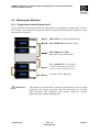
UltiMate® 3000 Viper™ Capillary Kits for Intelligent LC (LCi) System Solutions Quick Installation Guides January 2010 Rev. 02 © 2010 Dionex Table of Contents 1. Introduction ...................................................................................................................... 1 1.1 How to Use this Manual ............................................................................................. 1 1.2 Definition of LCi ........................................................................................................ 2 1.3 Typical System Setups ............................................................................................... 2 1.3.1 Single-Stack ........................................................................................................... 2 1.3.2 Dual-Stack .............................................................................................................. 3 1.4 Viper Connections ...................................................................................................... 3 1.5 Viper Capillary Kits and Packaging ........................................................................... 5 1.5.1 Capillary Kits for Single Stacks ............................................................................. 5 1.5.2 LCi Capillary Kits .................................................................................................. 7 1.6 Viper Labeling............................................................................................................ 8 1.7 General System Preparation ....................................................................................... 9 1.8 Connecting the Eluent Line to the Solvent Reservoir ................................................ 9 1.9 Using 10-Port Instead of 6-Port TCC-3x00 Valves ................................................. 11 2. Viper™ Tandem Operation Capillary Kits, Dual-Ternary Standard (P/N 6040.2804) or Rapid Separation (P/N 6040.2803) ............................................... 13 2.1 Benefits of Tandem Operation ................................................................................. 13 2.2 Scope of Delivery ..................................................................................................... 13 2.3 Stacking the Modules ............................................................................................... 14 2.4 Flow Schematic ........................................................................................................ 15 3. Viper™ Application Switching Capillary Kits, Dual-Ternary Standard (P/N 6040.2806) or Rapid Separation (P/N 6040.2805) ............................................... 17 3.1 Benefits of Application Switching ........................................................................... 17 3.2 Scope of Delivery ..................................................................................................... 17 3.3 Stacking the Modules ............................................................................................... 18 3.4 Flow Schematic ........................................................................................................ 19 4. Viper™ On-Line SPE Capillary Kits, Dual-Ternary Standard (P/N 6040.2802) or Rapid Separation (P/N 6040.2801) ............................................... 21 4.1 Benefits of On-line SPE ........................................................................................... 21 4.2 Scope of Delivery ..................................................................................................... 21 4.3 Stacking the Modules ............................................................................................... 22 4.4 Flow Schematic ........................................................................................................ 23 5. Viper™ Parallel LC Capillary Kits, Dual-Ternary Standard (P/N 6040.2810) or Rapid Separation (P/N 6040.2809) ............................................... 25 5.1 Benefits of Parallel LC ............................................................................................. 25 5.2 Scope of Delivery ..................................................................................................... 25 5.3 Stacking the Modules ............................................................................................... 26 5.4 Flow Schematic ........................................................................................................ 27 6. Viper™ Automated Method Scouting Kits, Quaternary Standard (P/N 6040.2808) or Rapid Separation (P/N 6040.2807) ............................................... 29 6.1 Benefits of Automated Method Scouting ................................................................. 29 6.2 Scope of Delivery ..................................................................................................... 29 6.2.1 Automated Method Scouting ............................................................................... 29 6.2.2 Extension Kit for Automated Method Scouting (P/N 6040.0100) ....................... 30 6.3 Stacking the Modules ............................................................................................... 31 6.3.1 Single-stack without Extension Kit ...................................................................... 31 January 2010 Rev. 02 © 2010 Dionex Page i ® UltiMate 3000 Viper™ Capillary Kits for Intelligent LC (LCi) System Solutions Quick Installation Guides 6.3.2 Dual-stack with Extension Kit ............................................................................. 32 6.4 Flow Schematics ...................................................................................................... 33 6.4.1 Single-stack without Extension Kit ...................................................................... 33 6.4.2 Dual-stack with Extension Kit ............................................................................. 35 Parts ......................................................................................................................................... 37 Page ii Rev. 02 © 2010 Dionex January 2010 ® UltiMate 3000 Viper™ Capillary Kits for Intelligent LC (LCi) System Solutions Quick Installation Guides 1. Introduction 1.1 How to Use this Manual This document is provided as a quick installation guide for the Dionex UltiMate® 3000 LCi solutions. It is assumed that the individual using this manual has sufficient training in the use of analytical instrumentation, has a basic knowledge of the Chromeleon Chromatography Data System, and is aware of the potential hazards including (but not limited to) electrical hazards, chemical solvent hazards, exposure to UV radiation, and the exposure to pressurized solvents. The quick installation guides are provided 'as is'. They explain the basic installation steps for a standard (SD) or rapid separation (RS) UltiMate 3000 HPLC System in conjunction with different Viper™ capillary kits. The installation procedure for these application kits is identical for both the SD and RS kit versions. The only difference between the SD and RS kits is the inner diameter of the flexible Viper capillaries, i.e., 0.18 mm/0.007” ID for the SD versions and 0.13 mm/0.005" ID for the RS versions. Please note that all capillaries connected directly to a pump feature an ID of 0.18 mm/0.007” to reduce backpressure. Most kits are predominantly designed for use with a single-stack system configuration (1.3) and for column lengths of up to 250 mm. All delivered kits work for common chromatographic scenarios. For extreme individual requirements (e.g. combining a 30 mm column with a 300 mm column in Parallel LC), it might be necessary to complement certain connections with additional capillaries. Each chapter provides a recommended schematic system setup. In general, the system setup in a dual-stack configuration is also possible; however, this might imply some restrictions which are outlined in the individual sections, if present. Chapter 1 has to be considered with each individual chapter on a dedicated kit. For additional module-specific information, refer to the related device manuals. Every effort has been made to supply complete and accurate information. Dionex assumes no responsibility for any errors that may appear in this document. This document is believed to be complete and accurate at the time of publication. In no event shall Dionex be liable for incidental or consequential damages in connection with or arising from the use of this document. The information contained in this document is subject to change without notice. We appreciate your help in eliminating any errors that may appear in this document. All rights reserved, including those for photomechanical reproduction and storage on electronic media. No part of this publication may be copied or distributed, transmitted, transcribed, stored in a retrieval system, or transmitted into any human or computer language, in any form or by any means, electronic, mechanical, magnetic, manual, or otherwise, or disclosed to third parties without written permission of Dionex. January 2010 Rev. 02 © 2010 Dionex Page 1 ® UltiMate 3000 Viper™ Capillary Kits for Intelligent LC (LCi) System Solutions Quick Installation Guides 1.2 Definition of LCi Dionex has developed a number of “Intelligent LC” (LCi) solutions to allow analysts to obtain the best possible combination of performance, reliability and ease-of-operation of their HPLC system(s). These solutions combine UltiMate 3000 hardware, Chromeleon software, and Dionex column chemistries to solve typical analytical challenges, such as method development, sample preparation, or increasing throughput and productivity. 1.3 Typical System Setups 1.3.1 Single-Stack In many cases, bench space is limited; hence the Dionex UltiMate 3000 systems are designed to consume as little space as possible. We assume that a single-stack setup is the most common case; therefore, the LCi capillary kits have been optimized for this scenario. Figure 1: UltiMate 3000 system as a single stack Note: Page 2 Figure 1 illustrates the course of the flexible Viper capillaries in general. Dionex recommends installing all capillaries inside the modules as needed. Rev. 02 © 2010 Dionex January 2010 ® UltiMate 3000 Viper™ Capillary Kits for Intelligent LC (LCi) System Solutions Quick Installation Guides 1.3.2 Dual-Stack Whenever bench space is of no concern but reduced system height is more important to users, the system can be configured as a dual-stack. Several different combinations are conceivable, depending on the kind and number of modules included in a system. The Viper LCi capillary kits have been carefully developed to cover as many individual situations as possible for the use of all UltiMate 3000 modules in single-stack or dual-stack configurations. In some cases, however, limitations may occur. The details on possible limitations will be outlined in the according paragraphs. Figure 2 illustrates the two most common dual-stack configurations. Figure 2: Dual-stack with U-shaped flow profile Figure 3: Dual-stack with Z-shaped flow profile 1.4 Viper Connections When working with small column volumes, capillaries and connections require special attention. But even with conventional columns and moderate pressures, mediocre connections can cause retention time shifts and peak distortions. Conventional stainless steel HPLC connectors use a ferrule and a nut to establish connections. A flaw of the conventional design is that a void volume-free connection is not guaranteed, particularly when changing the tubing between differently shaped threads (e.g. when changing a column). Viper connectors provide zero dead volume by sealing at the tubing tip, hence ensuring optimized connections. Viper is a revolutionary finger tight fitting system, which provides ease of use and dead-volumefree plumbing of conventional HPLC and modern UHPLC systems. Together with 1/32” flexible stainless steel (SST) capillaries, it opens a new dimension in modern liquid chromatography (LC). Viper improves chromatographic results, independent from column brands and system back pressures, and allows for connecting LC modules, valves, and columns quickly, easily, and reproducibly without any additional tools. Even though Viper withstands UHPLC backpressures of up to 1,200 bar (17,400 psi), it is a finger tight fitting system, which requires only small torques to seal. Therefore, it is essential to obey the following guidelines to avoid damages by over-tightening. January 2010 Rev. 02 © 2010 Dionex Page 3 ® UltiMate 3000 Viper™ Capillary Kits for Intelligent LC (LCi) System Solutions Quick Installation Guides Figure 4: Schematic for tightening a Viper fitting Attach Viper to the target thread and tighten the screw slowly until you feel the very first resistance. This is the 0° mark. Do not use tools other than the black knurl for opening and closing a connection. Tighten the screw clockwise to an angle between 0° and 45° and start operating your LC system at the desired working pressure. Verify that all connections seal properly. Usually, the Viper fitting is tight for pressures up to 1,200 bar (17,400 psi) after the first attempt. If leakage occurs under these conditions, tighten the screw(s) gradually further until the connection seals properly. Do not turn the screw beyond an angle of 90° to avoid damages of the PEEK seal by over-tightening. Do not apply brute force. To extend the life-time of Viper, open and close connections only at atmospheric system pressures. Opening and closing Viper connections at high system pressures may reduce the lifetime of the fitting system. If you are unable to get a Viper connection tight, call your local Dionex representative or replace it with a new capillary. Figure 5: 10-port valve equipped with Viper fittings Page 4 Rev. 02 © 2010 Dionex January 2010 ® UltiMate 3000 Viper™ Capillary Kits for Intelligent LC (LCi) System Solutions Quick Installation Guides 1.5 Viper Capillary Kits and Packaging 1.5.1 Capillary Kits for Single Stacks All UltiMate 3000 RS systems are delivered with a dedicated set of 3 Viper capillaries for system plumbing. In addition, dedicated Viper capillary RS and SD kits containing 3 capillaries each are available to equip Dionex UltiMate 3000 systems with Viper. Figure 6: Packaging box for Viper RS and SD capillary kits for UltiMate 3000 systems (single system, see Figure 1). The opposite side of the foam inlay allows for shipment of Viper capillaries with lengths of up to 1,000 mm. January 2010 Rev. 02 © 2010 Dionex Page 5 ® UltiMate 3000 Viper™ Capillary Kits for Intelligent LC (LCi) System Solutions Quick Installation Guides 1.5.1.1 Scope of Delivery 1.5.1.1.1 Viper Capillary Kit, RS System Table 1: Scope of delivery for the Viper capillary kit, RS system (P/N 6040.2301) Description Quantity Viper capillary (SST), ID x L 0.18 mm/0.007” x 450 mm 1 pc. Viper capillary (SST), ID x L 0.13 mm/0.005” x 350 mm 1 pc. Viper capillary (SST), ID x L 0.13 mm/0.005” x 250 mm 1 pc. Viper Installation and Operation Guide, short version 1 pc. 1.5.1.1.2 Viper Capillary Kit, SD System Table 2: Scope of delivery for the Viper capillary kit, SD system (P/N 6040.2302) Description Quantity Viper capillary (SST), ID x L 0.18 mm/0.007” x 450 mm 1 pc. Viper capillary (SST), ID x L 0.18 mm/0.005” x 350 mm 1 pc. Viper capillary (SST), ID x L 0.18 mm/0.005” x 250 mm 1 pc. Viper Installation and Operation Guide, short version 1 pc. Page 6 Rev. 02 © 2010 Dionex January 2010 ® UltiMate 3000 Viper™ Capillary Kits for Intelligent LC (LCi) System Solutions Quick Installation Guides 1.5.2 LCi Capillary Kits All Viper LCi capillary kits are delivered in a high-quality box with a foam inlay. Independent of the ordered kit, you will always receive the same box, accommodating all necessary accessories and capillaries for your individual LCi kit. Figure 7: Packaging box for all Viper LCi capillary kits. January 2010 Rev. 02 © 2010 Dionex Page 7 ® UltiMate 3000 Viper™ Capillary Kits for Intelligent LC (LCi) System Solutions Quick Installation Guides 1.6 Viper Labeling Each Viper capillary comes with a labeling clip. This clip can be easily detached and reattached to 1/16” and 1/32” OD capillaries. In addition, a set of 5 blank clips and stickers is supplied for individual labeling purposes. Figure 8: Removable labeling clip with sticker for individual capillary labeling. Page 8 Rev. 02 © 2010 Dionex January 2010 ® UltiMate 3000 Viper™ Capillary Kits for Intelligent LC (LCi) System Solutions Quick Installation Guides 1.7 General System Preparation Allow the system modules to adapt to ambient temperature for 4 hours to allow for potential condensation to evaporate. Do not connect the units to the mains during this period. If condensation is still detected after 4 hours, allow the system to continue to warm up to ambient temperature without connecting it to the mains, until all condensation is completely gone. Place the system on a firm and level surface that is free of vibrations. Make sure that the surface is resistant against LC solvents. Avoid locations with extreme changes in temperature (such as direct sunlight or drafts) and high air humidity. Note: For information about the power and communication connections (LAN, USB) as well as the installation procedures for other components, such as the Active Rear-Seal Wash System, please refer to the operating instructions of the system components. 1.8 Connecting the Eluent Line to the Solvent Reservoir 1. Feed the eluent line through the retaining guide and then into the opening in the reservoir cap. 2. Assemble the eluent filter Figure 9: Eluent filter components 3. Slide the eluent filter assembly onto the end of the eluent line. Verify that the end of the eluent line is cut straight and is not deformed. If necessary, cut the tubing with a sharp knife or blade. Use only the eluent lines shipped with the solvent rack. 4. Place the complete assembly in the solvent reservoir. 5. Hand-tighten the solvent reservoir caps. January 2010 Rev. 02 © 2010 Dionex Page 9 ® UltiMate 3000 Viper™ Capillary Kits for Intelligent LC (LCi) System Solutions Quick Installation Guides Filter holder with filter frit Retaining guide Figure 10: Handling of the eluent filter frit Note: To exchange the tubing, first remove the frit, and then remove the eluent tube before removing the retaining guide. Important: Always use eluent tubing with filter frits for drawing eluents from the eluent bottles. This prevents contamination of the HPLC system. Note: Page 10 Regularly check the frits for permeability. Especially when working with aqueous solvents, algae and other microorganisms can grow on the frits causing clogging. Therefore, exchange the solvents at regular intervals. Rinse the bottles thoroughly with fresh eluent before reusing them. Replace the frits (P/N 6268.0110), as necessary. Rev. 02 © 2010 Dionex January 2010 ® UltiMate 3000 Viper™ Capillary Kits for Intelligent LC (LCi) System Solutions Quick Installation Guides 1.9 Using 10-Port Instead of 6-Port TCC-3x00 Valves The installation steps for the Automated Application Switching, On-line Sample Preparation and Parallel LC capillary kits in this document refer to the use of 2-position 6-port switching valves. However, TCC-3x00 column compartments equipped with 2-position 10-port switching valves can also be used for these applications. Compared to the 6-port valve setup, the capillaries have to be connected to the identical port numbers of a 10-port valve, as illustrated below. Figure 11: Using a 10-port valve as a 6-port valve by employing any suitable capillary connection to shortcut ports 7 and 10. The 6-port valve has a direct fluidic connection between port 1 and port 6. To achieve this fluidic connection for a 10-port valve, Dionex recommends connecting ports 7 and 10 with an additional suitable capillary. The inner diameter of this capillary should be 0.13 mm (0.005″) for a rapid separation (RS) setup or 0.18 mm (0.007″) for a standard (SD) setup. Ports 8 and 9 are not used, and are therefore not plumbed. To avoid false leak alarms, however, these ports should be sealed with plugs or connected to additional (unused) capillaries. Important: Neither the capillary needed to connect port 7 with port 10, nor the plugs or additional capillaries for connecting ports 8 and 9, are included in the delivery. Please note, that all capillary labels and descriptions within this guide are valid also for the described 10-port setup. However, in some scenarios, it might be beneficial to use a different approach. January 2010 Rev. 02 © 2010 Dionex Page 11 ® UltiMate 3000 Viper™ Capillary Kits for Intelligent LC (LCi) System Solutions Quick Installation Guides Page 12 Rev. 02 © 2010 Dionex January 2010 ® UltiMate 3000 Viper™ Capillary Kits for Intelligent LC (LCi) System Solutions Quick Installation Guides 2. Viper™ Tandem Operation Capillary Kits, DualTernary Standard (P/N 6040.2804) or Rapid Separation (P/N 6040.2803) 2.1 Benefits of Tandem Operation Tandem operation is an LCi solution for increasing the throughput of gradient separations between 50% and 100%. With Tandem LC, two different flow paths are used, allowing for off-line equilibration of one column while a second column is used for the current analysis. Tandem LC offers a throughput increase without the need for further method optimization. This eliminates the need for method revalidation and revision of corresponding documentation, which might be necessary with other throughput-increase approaches. The HPLC system with tandem operation includes a dual-gradient pump with the ability to perform two ternary gradients at the same time, a thermostatted column compartment with one 2-position 10-port valve for column switching, a split loop well-plate autosampler, and a stackable Dionex detector, all of which are fully controlled by the Chromeleon Chromatography Data System. Prior to installation, please consider chapter 1 for important additional information. 2.2 Scope of Delivery Table 3: Scope of delivery for the Viper capillary kit, RS system, Tandem Operation, SST (P/N 6040.2803), and Viper capillary kit, SD system, Tandem Operation, SST (P/N 6040.2804) Description Quantity Viper capillary (SST), ID x L 0.13 mm/0.005” or 0.18 mm/0.007” x 150 mm 1 pc. Viper capillary (SST), ID x L 0.13 mm/0.005” or 0.18 mm/0.007” x 250 mm 2 pcs. Viper capillary (SST), ID x L 0.13 mm/0.005” or 0.18 mm/0.007” x 350 mm 1 pc. Viper capillary (SST), ID x L 0.18 mm/0.007” x 450 mm 1 pc. Viper capillary (SST), ID x L 0.13 mm/0.005” or 0.18 mm/0.007” x 550 mm 3 pcs. Viper capillary (SST), ID x L 0.18 mm/0.007” x 950 mm 1 pc. PEEK capillary for valve waste connection, 1/16”, 0.25 mm/0.010” ID 1m Viper union for direct connection of two Viper capillaries 2 pcs. Capillary marker 5 pcs. Labels for capillary marker 8 pcs. One-piece finger tight fitting 1/16", PEEK 1 pc. Eluent pre-heater with Viper fitting, ID 0.13 mm ID, volume 2 µL (Incl. in RS kit only) 1 pc. Laminated flow scheme for tandem operation 1 pc. Quick installation guide UltiMate 3000 Viper Capillary Kits for Intelligent LC (LCi) System Solutions 1 pc. January 2010 Rev. 02 © 2010 Dionex Page 13 ® UltiMate 3000 Viper™ Capillary Kits for Intelligent LC (LCi) System Solutions Quick Installation Guides 2.3 Stacking the Modules Please stack the modules as shown below. The picture is a schematic to illustrate the course of the flexible Viper capillaries in general. Dionex recommends installing all capillaries inside the modules as needed. SRD-3600 Solvent Rack and Degasser DGP-3600RS/SD Dual-Gradient Pump WPS-3000(T)SL/(T)RS inline Split Loop Autosampler TCC-3000RS/SD Thermostatted Column Compartment with 1x 2-position 10-port switching valve (right) Stackable Dionex Detector Important: Page 14 All modules are primed with 2-propanol at the factory. Prior to initial operation of the system, make sure that all used solvents are miscible with 2-propanol and equilibrate your system. Otherwise, perform appropriate intermediate flushing steps. Rev. 02 © 2010 Dionex January 2010 ® UltiMate 3000 Viper™ Capillary Kits for Intelligent LC (LCi) System Solutions Quick Installation Guides 2.4 Flow Schematic The figure below shows the schematic setup of the tandem operation configuration. Install your Viper capillaries according to the information of Table 4 and the system stack schematic ( 2.3). Figure 12: Flow schematic of tandem operation setup Table 4: Detailed description of capillary connections of the tandem operation setup Description of Connections Capillary Dimensions (ID x L) PumpLeft outlet – TCC 10-port valve right, port 8 0.18 mm/0.007” x 950 mm PumpRight outlet – WPS sampler valve, port 5 0.18 mm/0.007” x 450 mm TCC 10-port valve right, port 7 – Column 1 inlet RS: 0.13 mm/0.005” x 250 mm SD: 0.18 mm/0.007” x 250 mm TCC 10-port valve right, port 5 – Column 2 inlet RS: 0.13 mm/0.005” x 250 mm SD: 0.18 mm/0.007” x 250 mm TCC 10-port valve right, port 4 – TCC 10-port valve right, port 9 RS: 0.13 mm/0.005” x 150 mm SD: 0.18 mm/0.007” x 150 mm TCC 10-port valve right, port 3 – Waste 0.25 mm/0.010” x 1,000 mm (PEEK) WPS sampler valve, port 4 – TCC 10-port valve right, port 6 RS: 0.13 mm/0.005” x 350 mm SD: 0.18 mm/0.007” x 350 mm Column 1 outlet – TCC 10-port valve right, port 10 RS: 0.13 mm/0.005” x 550 mm SD: 0.18 mm/0.007” x 550 mm Column 2 outlet – TCC 10-port valve right, port 2 RS: 0.13 mm/0.005” x 550 mm SD: 0.18 mm/0.007” x 550 mm TCC 10-port valve right, port 1 – Detector inlet RS: 0.13 mm/0.005” x 550 mm SD: 0.18 mm/0.007” x 550 mm January 2010 Rev. 02 © 2010 Dionex Page 15 ® UltiMate 3000 Viper™ Capillary Kits for Intelligent LC (LCi) System Solutions Quick Installation Guides Note: Page 16 In case of a dual-stack setup, the TCC 10-port valve right turns into a TCC 10-port valve left. Both stacks should have a distance of about 7 cm (2.8 inches). Connecting a post-column cooler with a stackable Dionex detector does not work without additional capillaries when setting up the system in the U-configuration (1.3.2). Rev. 02 © 2010 Dionex January 2010 ® UltiMate 3000 Viper™ Capillary Kits for Intelligent LC (LCi) System Solutions Quick Installation Guides 3. Viper™ Application Switching Capillary Kits, DualTernary Standard (P/N 6040.2806) or Rapid Separation (P/N 6040.2805) 3.1 Benefits of Application Switching Automated Application Switching is an LCi solution for increasing system productivity by running two applications consecutively and independently on one UltiMate 3000 system. Automated application switching eliminates manual rinse and equilibration steps, which are usually part of application changes. After the system has completed the analysis of one set of samples, it automatically prepares and runs a second application for a different or the same sample set. Columns, solvents, and samples may be completely different as there is no interference between both methods. The HPLC system with Automated Application Switching includes a dual-gradient pump with the ability to perform two ternary gradients at the same time, a thermostatted column compartment with one 2-position 10-port switching valve (right) and one 2-position 6-port switching valve (left) for column switching, a split loop well-plate autosampler, and a stackable Dionex detector, all of which are fully controlled by the Chromeleon Chromatography Data System. Prior to installation, please consider chapter 1 for important additional information. 3.2 Scope of Delivery Table 5: Scope of delivery for the Viper capillary kit, RS system, Application Switching, SST (P/N 6040.2805), and Viper capillary kit, SD system, Application Switching, SST, (P/N 6040.2806) Description Quantity Viper capillary (SST), ID x L 0.13 mm/0.005” or 0.18/0.007” x 250 mm 2 pcs. Viper capillary (SST), ID x L 0.13 mm/0.005” or 0.18/0.007” x 350 mm 4 pcs. Viper capillary (SST), ID x L 0.13 mm/0.005” or 0.18/0.007” x 650 mm 2 pcs. Viper capillary (SST), ID x L 0.13 mm/0.005” or 0.18/0.007” x 750 mm 1 pc. Viper capillary (SST), ID x L 0.18 mm/0.007” x 750 mm 1 pc. Viper capillary (SST), ID x L 0.18 mm/0.007” x 850 mm 1 pc. PEEK capillary for valve waste connection, 1/16”, 0.25 mm/0.010” ID 2m Viper union for direct connection of two Viper capillaries 2 pcs. Capillary marker 5 pcs. Labels for capillary marker 8 pcs. One-piece finger tight fitting 1/16", PEEK 2 pcs. Laminated flow scheme for automated application switching 1 pc. Quick installation guide UltiMate 3000 Viper Capillary Kits for Intelligent LC (LCi) System Solutions 1 pc. January 2010 Rev. 02 © 2010 Dionex Page 17 ® UltiMate 3000 Viper™ Capillary Kits for Intelligent LC (LCi) System Solutions Quick Installation Guides 3.3 Stacking the Modules Please stack the modules as shown below. The picture is a schematic to illustrate the course of the flexible Viper capillaries in general. Dionex recommends installing all capillaries inside the modules as needed. SRD-3600 Solvent Rack and Degasser DGP-3600RS/SD Dual-Gradient Pump WPS-3000(T)SL/(T)RS inline Split Loop Autosampler TCC-3000RS/SD Thermostatted Column Compartment with 1x 2-position 10-port switching valve (right) and 1 x 2-position 6-port switching valve (left) Stackable Dionex Detector Important: Page 18 All modules are primed with 2-propanol at the factory. Prior to initial operation of the system, make sure that all used solvents are miscible with 2-propanol and equilibrate your system. Otherwise, perform appropriate intermediate flushing steps. Rev. 02 © 2010 Dionex January 2010 ® UltiMate 3000 Viper™ Capillary Kits for Intelligent LC (LCi) System Solutions Quick Installation Guides 3.4 Flow Schematic The figure below shows the schematic setup of the application switching configuration. Install your Viper capillaries according to the information of Table 6 and the system stack schematic ( 3.3). Figure 13: Flow schematic of the automated application switching setup January 2010 Rev. 02 © 2010 Dionex Page 19 ® UltiMate 3000 Viper™ Capillary Kits for Intelligent LC (LCi) System Solutions Quick Installation Guides Table 6: Detailed description of capillary connections of the automated application switching setup Description of Connections Capillary Dimensions (ID x L) PumpLeft outlet – TCC 10-port valve right, port 2 0.18 mm/0.007” x 850 mm PumpRight outlet – TCC 10-port valve right, port 4 0.18 mm/0.007” x 750 mm TCC 10-port valve right, port 1 – Column 1 inlet RS: 0.13 mm/0.005” x 350 mm SD: 0.18 mm/0.007” x 350 mm TCC 10-port valve right, port 5 – Column 2 inlet RS: 0.13 mm/0.005” x 350 mm SD: 0.18 mm//0.007” x 350 mm WPS sampler valve, port 5 – TCC 10-port valve right, port 3 RS: L 0.13 mm//0.005” x 350 mm SD: 0.18 mm//0.007” x 350 mm TCC 10-port valve right, port 10 – TCC 6-port valve left, port 6 RS: 0.13 mm//0.005” x 650 mm SD: 0.18 mm//0.007” x 650 mm TCC 10-port valve right, port 6 – TCC 6-port valve left, port 2 RS: 0.13 mm//0.005” x 650 mm SD: 0.18 mm/0.007” x 650 mm WPS sampler valve, port 4 – TCC 6-port valve left, port 1 RS: 0.13 mm//0.005” x 750 mm SD: 0.18 mm/0.007” x 750 mm TCC 10-port valve right, port 7 – Waste 0.25 mm/0.010” x 1,000 mm (PEEK) TCC 10-port valve right, port 9 – Waste 0.25 mm//0.010” x 1,000 mm (PEEK) Column 1 outlet – TCC 6-port valve left, port 5 RS: 0.13 mm/0.005” x 250 mm SD: 0.18 mm/0.007” x 250 mm Column 2 outlet – TCC 6-port valve left, port 3 RS: 0.13 mm/0.005” x 250 mm SD: 0.18 mm/0.007” x 250 mm TCC 6-port valve left, port 4 – Detector inlet RS: 0.13 mm/0.005” x 350 mm SD: 0.18 mm/0.007” x 350 mm Note: Page 20 In case of a dual-stack setup, the TCC 10-port valve right turns into a TCC 10-port valve left and the TCC 6-port valve left turns into a TCC 6-port valve right. Both stacks should have a distance of about 7 cm (2.8 inches). The capillary connection between valve right and detector has to be extended from 350 mm to 550 mm. Connecting a post-column cooler with a stackable Dionex detector does not work without additional capillaries when setting up the system in the U-configuration (1.3.2). Rev. 02 © 2010 Dionex January 2010 ® UltiMate 3000 Viper™ Capillary Kits for Intelligent LC (LCi) System Solutions Quick Installation Guides 4. Viper™ On-Line SPE Capillary Kits, Dual-Ternary Standard (P/N 6040.2802) or Rapid Separation (P/N 6040.2801) 4.1 Benefits of On-line SPE Automated on-line solid phase extraction is an LCi solution allowing for easy and automated isolation of analytes from a complex matrix. The automated on-line SPE reduces time, labor and cost, and thus increases productivity. After injection of an untreated sample, the on-line SPE-LC allows for automated sample cleanup and/or analyte enrichment. Samples can run unattended, which increases the workload per system. The HPLC system with on-line SPE includes a dual-gradient pump with the ability to perform two ternary gradients at the same time, a thermostatted column compartment with one 2-position 6-port switching valve for column switching, a split loop well-plate autosampler, and a stackable Dionex detector, all of which are fully controlled by the Chromeleon Chromatography Data System. Prior to installation, please consider chapter 1 for important additional information. 4.2 Scope of Delivery Table 7: Scope of delivery for the Viper capillary kit, RS system, on-line SPE, SST (P/N 6040.2801), and Viper capillary kit, SD system, on-line SPE, SST (P/N 6040.2802) Description Quantity Viper capillary (SST), ID x L 0.13 mm/0.005” x 250 mm or 0.18 mm/0.007” x 250 mm 2 pcs. Viper capillary (SST), ID x L 0.13 mm/0.005” x 350 mm or 0.18 mm/0.007” x 350 mm 3 pcs. Viper capillary (SST), ID x L 0.18 mm/0.007” x 450 mm 1 pc. Viper capillary (SST), ID x L 0.18 mm/0.007” x 950 mm 1 pc. PEEK capillary for valve waste connection, 1/16”, 0.25 mm/0.010” ID 1m Viper union for direct connection of two Viper capillaries 2 pcs. Capillary marker 5 pcs. Labels for capillary marker 8 pcs. One-piece finger tight fitting 1/16", PEEK 2 pcs. Laminated flow scheme for on-line SPE 1 pc. Quick installation guide UltiMate 3000 Viper Capillary Kits for Intelligent LC (LCi) System Solutions 1 pc. January 2010 Rev. 02 © 2010 Dionex Page 21 ® UltiMate 3000 Viper™ Capillary Kits for Intelligent LC (LCi) System Solutions Quick Installation Guides 4.3 Stacking the Modules Please stack the modules as shown below. The picture is a schematic to illustrate the course of the flexible Viper capillaries in general. Dionex recommends installing all capillaries inside the modules as needed. SRD-3600 Solvent Rack and Degasser DGP-3600RS/SD Dual-Gradient Pump WPS-3000(T)SL/(T)RS inline Split Loop Autosampler TCC-3000RS/SD Thermostatted Column Compartment with 1x 2-position 6-port switching valve Stackable Dionex Detector Important: Page 22 All modules are primed with 2-propanol at the factory. Prior to initial operation of the system, make sure that all used solvents are miscible with 2-propanol and equilibrate your system. Otherwise, perform appropriate intermediate flushing steps. Rev. 02 © 2010 Dionex January 2010 ® UltiMate 3000 Viper™ Capillary Kits for Intelligent LC (LCi) System Solutions Quick Installation Guides 4.4 Flow Schematic The figure below shows the schematic setup of the on-line SPE configuration. Install your Viper capillaries according to the information of Table 8 and the system stack schematic ( 4.3). Figure 14: Flow schematic of the on-line SPE setup Table 8: Detailed description of capillary connections of the on-line SPE setup Description of Connections Capillary Dimensions (ID x L) PumpLeft outlet – TCC 6-port valve right, port 5 0.18 mm/0.007” x 950 mm PumpRight outlet – WPS sampler valve, port 5 0.18 mm/0.007” x 450 mm TCC 6-port valve right, port 3 – SPE column inlet RS: 0.13 mm/0.005” x 250 mm SD: 0.18 mm/0.007” x 250 mm TCC 6-port valve right, port 4 – Column inlet RS: 0.13 mm/0.005” x 250 mm SD: 0.18 mm/0.007” x 250 mm WPS sampler valve, port 4 – TCC 6-port valve right, port 2 RS: 0.13 mm/0.005” x 350 mm SD: 0.18 mm/0.007” x 350 mm SPE column outlet – TCC 6-port valve left, port 6 RS: 0.13 mm/0.005” x 350 mm SD: 0.18 mm/0.007” x 350 mm Column outlet – Detector inlet RS: 0.13 mm/0.005” x 350 mm SD: 0.18 mm/0.007” x 350 mm January 2010 Rev. 02 © 2010 Dionex Page 23 ® UltiMate 3000 Viper™ Capillary Kits for Intelligent LC (LCi) System Solutions Quick Installation Guides Note: Page 24 In case of a dual-stack setup, the TCC 6-port valve right turns into a TCC 6-port valve left. Both stacks should have a distance of about 7 cm (2.8 inches). Connecting a post-column cooler with a stackable Dionex detector does not work without additional capillaries when setting up the system in the U-configuration (1.3.2). Rev. 02 © 2010 Dionex January 2010 ® UltiMate 3000 Viper™ Capillary Kits for Intelligent LC (LCi) System Solutions Quick Installation Guides 5. Viper™ Parallel LC Capillary Kits, Dual-Ternary Standard (P/N 6040.2810) or Rapid Separation (P/N 6040.2809) 5.1 Benefits of Parallel LC Parallel LC is an LCi solution for increasing the throughput for both isocratic and gradient separations by efficient use of hardware. The Parallel LC system uses two pumps and two detectors, and shares one autosampler and one column compartment. This allows the user to operate one Parallel LC setup as two independent HPLC systems, and therefore increases productivity. Chromeleon treats this configuration as two completely independent systems and manages seamless autosampler and column compartment sharing. A specialty of the Parallel LC configuration is the recommended dual-stack setup ( 5.3). The HPLC system with a parallel setup includes a dual-gradient pump with the ability to perform two ternary gradients at the same time, a thermostatted column compartment with one 2-position 6-port switching valve for column switching, a split loop well-plate autosampler, and two stackable Dionex detectors, all of which are fully controlled by the Chromeleon Chromatography Data System. Prior to installation, please consider chapter 1 for important additional information. 5.2 Scope of Delivery Table 9: Scope of delivery for the Viper capillary kit, RS system, Parallel LC, SST (P/N 6040.2809), and Viper capillary kit, SD system, Parallel LC, SST (P/N 6040.2810) Description Quantity Viper capillary (SST), ID x L 0.13 mm/0.005” x 250 mm or 0.18 mm/0.007” x 250 mm 4 pcs. Viper capillary (SST), ID x L 0.13 mm/0.005” x 350 mm or 0.18 mm/0.007” x 350 mm 2 pcs. Viper capillary (SST), ID x L 0.18 mm/0.007” x 350 mm 1 pc. Viper capillary (SST), ID x L 0.18 mm/0.007” x 550 mm 1 pc. Viper union for direct connection of two Viper capillaries 2 pcs. Capillary marker 5 pcs. Labels for capillary marker 8 pcs. Eluent pre-heater with Viper fitting, ID 0.13 mm ID, volume 2 µL (Included in RS kit only) 1 pc. Laminated flow scheme for Parallel LC 1 pc. Quick installation guide UltiMate 3000 Viper Capillary Kits for Intelligent LC (LCi) System Solutions 1 pc. January 2010 Rev. 02 © 2010 Dionex Page 25 ® UltiMate 3000 Viper™ Capillary Kits for Intelligent LC (LCi) System Solutions Quick Installation Guides 5.3 Stacking the Modules Please stack the modules as shown below. The picture is a schematic to illustrate the course of the flexible Viper capillaries in general. Dionex recommends installing all capillaries inside the modules as needed. SRD-3600 Solvent Rack and Degasser Combination of two stackable Dionex Detectors DGP-3600RS/SD Dual-Gradient Pump WPS-3000(T)SL/ (T)RS inline Split Loop Autosampler TCC-3000RS/SD Thermostatted Column Compartment with 1x 2position 6-port switching valve The recommended distance between the two stacks is approximately 6 - 8 cm (2.4 - 3.2 inches). Important: Page 26 All modules are primed with 2-propanol at the factory. Prior to initial operation of the system, make sure that all used solvents are miscible with 2-propanol and equilibrate your system. Otherwise, perform appropriate intermediate flushing steps. Rev. 02 © 2010 Dionex January 2010 ® UltiMate 3000 Viper™ Capillary Kits for Intelligent LC (LCi) System Solutions Quick Installation Guides 5.4 Flow Schematic The figure below shows the Parallel LC setup. With this configuration, two Chromeleon instruments (“time bases”) share the column compartment and the autosampler. The autosampler is alternated between two parallel flow paths to allow for synchronized analyses on two individual columns. Two detectors independently and simultaneously acquire the related signals. Note: The eluents in both systems have to be fully miscible; both columns have to be operated at the same column temperature as they are located in the same column compartment; the initial eluent compositions on both columns should be comparable to support fast flow path switching; comparable cycle times for both methods are advantageous. To ease the installation of the capillaries, it is helpful to establish all connections at the TCC 6-port valve left first, and to position both towers at the recommended distance ( 5.3) for connecting the pumps and the autosampler afterwards. Columns with a length of 200 mm or more are optimally positioned at the lower end of the TCC. Figure 15: Flow schematic of the Parallel LC setup January 2010 Rev. 02 © 2010 Dionex Page 27 ® UltiMate 3000 Viper™ Capillary Kits for Intelligent LC (LCi) System Solutions Quick Installation Guides Table 10: Detailed description of capillary connections of the Parallel LC setup (dual-stack) Description of Connections Capillary Dimensions (ID x L) PumpLeft outlet – TCC 6-port valve left, port 6 0.18 mm/0.007” x 550 mm PumpRight outlet – TCC 6-port valve left, port 4 0.18 mm/0.007” x 350 mm TCC 6-port valve left, port 5 – WPS sampler valve, port 5 RS: 0.13 mm/0.005” x 250 mm SD: 0.18 mm/0.007” x 250 mm WPS sampler valve, port 4 – TCC 6-port valve left, port 2 RS: 0.13 mm/0.005” x 250 mm SD: 0.18 mm/0.007” x 250 mm TCC 6-port valve left, port 3 – Column 1 inlet RS: 0.13 mm/0.005” x 250 mm SD: 0.18 mm/0.007” x 250 mm TCC 6-port valve left, port 1 – Column 2 inlet RS: 0.13 mm/0.005” x 250 mm SD: 0.18 mm/0.007” x 250 mm Column 1 outlet – Detector 1 inlet RS: 0.13 mm/0.005” x 350 mm SD: 0.18 mm/0.007” x 350 mm Column 2 outlet – Detector 2 inlet RS: 0.13 mm/0.005” x 350 mm SD: 0.18 mm/0.007” x 350 mm Note: In case of a single-stack setup of the Parallel LC system, the TCC 6-port valve left turns into a TCC 6-port valve right. The capillary lengths have to be adapted as outlined in Table 11. Table 11: Detailed description of capillary connections of the Parallel LC setup (single-stack) Description of Connections Capillary Dimensions (ID x L) PumpLeft outlet – TCC 6-port valve left, port 6 0.18 mm/0.007” x 950 mm PumpRight outlet – TCC 6-port valve left, port 4 0.18 mm/0.007” x 950 mm TCC 6-port valve left, port 5 – WPS sampler valve, port 5 RS: 0.13 mm/0.005” x 550 mm SD: 0.18 mm/0.007” x 550 mm WPS sampler valve, port 4 – TCC 6-port valve left, port 2 RS: 0.13 mm/0.005” x 550 mm SD: 0.18 mm/0.007” x 550 mm TCC 6-port valve left, port 3 – Column 1 inlet RS: 0.13 mm/0.005” x 250 mm SD: 0.18 mm/0.007” x 250 mm TCC 6-port valve left, port 1 – Column 2 inlet RS: 0.13 mm/0.005” x 250 mm SD: 0.18 mm/0.007” x 250 mm Column 1 outlet – Detector 1 inlet RS: 0.13 mm/0.005” x 350 mm SD: 0.18 mm/0.007” x 350 mm Column 2 outlet – Detector 2 inlet RS: 0.13 mm/0.005” x 350 mm SD: 0.18 mm/0.007” x 350 mm Page 28 Rev. 02 © 2010 Dionex January 2010 ® UltiMate 3000 Viper™ Capillary Kits for Intelligent LC (LCi) System Solutions Quick Installation Guides 6. Viper™ Automated Method Scouting Kits, Quaternary Standard (P/N 6040.2808) or Rapid Separation (P/N 6040.2807) 6.1 Benefits of Automated Method Scouting Automated Method Scouting is a powerful solution for the convenient determination of optimized analytical method parameters, such as pH, temperature, stationary phase, and solvent composition. Together with a thermostatted column compartment and two column selection valves, up to six different columns can be automatically scouted. All capillaries are color-coded for easy identification of columns and related flow paths. Analytical methods can be developed and optimized fully automated and unattended. Chromeleon software provides comprehensive mining tools for data evaluation; smart reports visualize all results clearly and instantaneously. A specialty of the Method Scouting configuration is the optional method scouting extension kit, which allows for the use of up to 9 additional different mobile phases. The recommended setup without the extension kit is the single stack, whereas the extension kit requires the dual-stack setup ( 5.3). The HPLC system with Automated Method Scouting includes a quaternary gradient pump, a thermostatted column compartment with two 6-position 7-port switching valves for column switching, a split loop well-plate autosampler, and preferably a diode array detector, all of which are fully controlled by the Chromeleon Chromatography Data System. Prior to installation, please consider chapter 1 for important additional information. 6.2 Scope of Delivery 6.2.1 Automated Method Scouting Table 12: Scope of delivery for the Viper capillary kit, RS system, Method Scouting, SST (P/N 6040.2807), and Viper capillary kit, SD system, Method Scouting, SST (P/N 6040.2808) Description Quantity Viper capillary (SST), ID x L 0.13 mm/0.005” x 150 mm or 0.18 mm/0.007” x 150 mm 1 pcs. Viper capillary (SST), ID x L 0.13 mm/0.005” x 250 mm or 0.18 mm/0.007” x 250 mm 7 pcs. Viper capillary (SST), ID x L 0.13 mm/0.005” x 350 mm or 0.18 mm/0.007” x 350 mm 6 pcs. Viper capillary (SST), ID x L 0.13 mm/0.005” x 450 mm or 0.18 mm/0.007” x 450 mm 1 pc. Viper capillary (SST), ID x L 0.18 mm/0.007” x 450 mm 1 pc. Viper union for direct connection of two Viper capillaries 7 pcs. Capillary marker 20 pcs. Labels for capillary marker 20 pcs. Capillary clip for color-coding, yellow 30 pcs. January 2010 Rev. 02 © 2010 Dionex Page 29 ® UltiMate 3000 Viper™ Capillary Kits for Intelligent LC (LCi) System Solutions Quick Installation Guides Description Quantity Capillary clip for color-coding, white 30 pcs. Capillary clip for color-coding, red 30 pcs. Capillary clip for color-coding, black 30 pcs. Capillary clip for color-coding, blue 30 pcs. Capillary clip for color-coding, green 30 pcs. Laminated flow scheme for Automated Method Scouting 1 pc. Quick installation guide UltiMate 3000 Viper Capillary Kits for Intelligent LC (LCi) System Solutions 1 pc. 6.2.2 Extension Kit for Automated Method Scouting (P/N 6040.0100) Table 13: Scope of delivery of the extension kit for Method Scouting, (P/N 6040.0100) Description Quantity SR-3000, Solvent Rack without degasser 1 pc. Solvent selection valve, 10-pos 11-port 1 pc. Mounting plate for solvent selection valve 1 pc. Viper capillary (SST), ID x L 0.13 mm/0.007” x 650 mm 1 pc. Viper capillary (SST), ID x L 0.18 mm/0.007” x 650 mm 1 pc. Viper capillary (SST), ID x L 0.13 mm/0.007” x 150 mm 1 pc. Viper capillary (SST), ID x L 0.18 mm/0.007” x 150 mm 1 pc. Viper union for direct connection of two Viper capillaries 2 pcs. Eluent bottle, 1 L 6 pcs. Eluent filter for additional solvent bottles 10 pcs. Retaining guide for solvent tubing 10 pcs. Sealing plug for eluent bottle screw cap 40 pcs. Eluent tubing, 1 m, for connecting 10 eluent bottles to the 10-pos 11-port valve 10 pcs. Eluent tubing, 0.6 m, for connecting the 10-pos 11-port valve to the LPG-3400 pump 1 pc. Laminated flow scheme for Automated Method Scouting 1 pc. Quick installation guide UltiMate 3000 Viper Capillary Kits for Intelligent LC (LCi) System Solutions 1 pc. Page 30 Rev. 02 © 2010 Dionex January 2010 ® UltiMate 3000 Viper™ Capillary Kits for Intelligent LC (LCi) System Solutions Quick Installation Guides 6.3 Stacking the Modules 6.3.1 Single-stack without Extension Kit Please stack the modules as shown below. The picture is a schematic to illustrate the course of the flexible Viper capillaries in general. Dionex recommends installing all capillaries inside the modules as needed. SRD-3600 Solvent Rack and Degasser LPG-3400RS/SD Quaternary Pump WPS-3000(T)SL/(T)RS inline Split Loop Autosampler TCC-3000RS/SD Thermostatted Column Compartment with 2x 6position 7-port switching valves Stackable Dionex Detector Important: January 2010 All modules are primed with 2-propanol at the factory. Prior to initial operation of the system, make sure that all used solvents are miscible with 2-propanol and equilibrate your system. Otherwise, perform appropriate intermediate flushing steps. Rev. 02 © 2010 Dionex Page 31 ® UltiMate 3000 Viper™ Capillary Kits for Intelligent LC (LCi) System Solutions Quick Installation Guides 6.3.2 Dual-stack with Extension Kit Please stack the modules as shown below. The picture is a schematic to illustrate the course of the flexible Viper capillaries in general. Dionex recommends installing all capillaries inside the modules as needed. For the use of the Method Scouting Extension Kit, a dual-stack is recommended. In combination with the second solvent rack, this setup offers space for up to 9 additional solvent bottles and the solvent selection valve to be placed on top of the system. Solvent Selection Valve with mounting plate SRD-3600 Solvent Rack and Degasser SR-3000 Solvent Rack LPG-3400RS/SD Quaternary Pump DAD-3000(RS) Diode Array Detector (recommended) WPS-3000(T)SL/(T)RS inline Split Loop Autosampler TCC-3000RS/SD Thermostatted Column Compartment with 2x 6-pos 7-port switching valves The recommended distance between the two stacks is approximately 10 cm (3.9 inches). Important: Page 32 All modules are primed with 2-propanol at the factory. Prior to initial operation of the system, make sure that all used solvents are miscible with 2-propanol and equilibrate your system. Otherwise, perform appropriate intermediate flushing steps. Rev. 02 © 2010 Dionex January 2010 ® UltiMate 3000 Viper™ Capillary Kits for Intelligent LC (LCi) System Solutions Quick Installation Guides 6.4 Flow Schematics 6.4.1 Single-stack without Extension Kit The figure below shows the schematic setup of the Method Scouting configuration as a single-stack, supporting up to four different eluents. Install your Viper capillaries according to the information of Table 14 and the system stack schematic ( 6.3.1). Note: All columns have to be operated at the same column temperature; in order to allow for fast and easy system flushing, one column can be replaced with a suitable capillary as a bypass (not included in delivery), or a column can be replaced by a Viper union to directly connect the two valves. The kit contains colored capillary clips for color-coding of the capillaries. For detailed information on the installation of the solvent selection valve, please refer to the related documentation. Figure 16: Flow schematic of the Method Scouting setup without extension kit (single-stack) January 2010 Rev. 02 © 2010 Dionex Page 33 ® UltiMate 3000 Viper™ Capillary Kits for Intelligent LC (LCi) System Solutions Quick Installation Guides Table 14: Detailed description of capillary connections of the Method Scouting setup (single-stack) Description of Connections Capillary Dimensions (ID x L) Pump outlet – WPS sampler valve, port 5 0.18 mm/0.007” x 450 mm WPS sampler valve, port 4 – TCC 7-port valve right, port 7 (center) RS: 0.13 mm/0.005” x 350 mm SD: 0.18 mm/0.007” x 350 mm TCC 7-port valve right, port 1 – Column 1 inlet RS: 0.13 mm/0.005” x 350 mm SD: 0.18 mm/0.007” x 350 mm TCC 7-port valve right, port 2 – Column 2 inlet RS: 0.13 mm/0.005” x 350 mm SD: 0.18 mm/0.007” x 350 mm TCC 7-port valve right, port 3 – Column 3 inlet RS: 0.13 mm/0.005” x 350 mm SD: 0.18 mm/0.007” x 350 mm TCC 7-port valve right, port 4 – Column 4 inlet RS: 0.13 mm/0.005” x 350 mm SD: 0.18 mm/0.007” x 350 mm TCC 7-port valve right, port 5 – Column 5 inlet RS: 0.13 mm/0.005” x 350 mm SD: 0.18 mm/0.007” x 350 mm TCC 7-port valve right, port 6 – Column 6 inlet RS: 0.13 mm/0.005” x 350 mm SD: 0.18 mm/0.007” x 350 mm Column 1 outlet – TCC 7-port valve left, port 1 RS: 0.13 mm/0.005” x 250 mm SD: 0.18 mm/0.007” x 250 mm Column 2 outlet – TCC 7-port valve left, port 2 RS: 0.13 mm/0.005” x 250 mm SD: 0.18 mm/0.007” x 250 mm Column 3 outlet – TCC 7-port valve left, port 3 RS: 0.13 mm/0.005” x 250 mm SD: 0.18 mm/0.007” x 250 mm Column 4 outlet – TCC 7-port valve left, port 4 RS: 0.13 mm/0.005” x 250 mm SD: 0.18 mm/0.007” x 250 mm Column 5 outlet – TCC 7-port valve left, port 5 RS: 0.13 mm/0.005” x 250 mm SD: 0.18 mm/0.007” x 250 mm Column 6 outlet – TCC 7-port valve left, port 6 RS: 0.13 mm/0.005” x 250 mm SD: 0.18 mm/0.007” x 250 mm TCC 7-port valve left, port 7 (center) – Detector inlet RS: 0.13 mm/0.005” x 450 mm SD: 0.18 mm/0.007” x 450 mm Note: Page 34 Limitations with the use of pre-column heater(s) and with the post-column cooler may apply, depending on number and dimensions of columns used. For the use with one single centralized pre-column heater, use a Viper union together with the 150 mm Viper capillary to allow for the installation of the pre-column heater between injection valve and TCC valve right. Rev. 02 © 2010 Dionex January 2010 ® UltiMate 3000 Viper™ Capillary Kits for Intelligent LC (LCi) System Solutions Quick Installation Guides 6.4.2 Dual-stack with Extension Kit The figure below shows the schematic setup of the Method Scouting configuration with the extension kit as a dual-stack, supporting up to 13 different eluents. Install your Viper capillaries according to the information of Table 15 and the system stack schematic ( 6.3.2). Note: All columns have to be operated at the same column temperature; in order to allow for fast and easy system flushing, one column can be replaced with a suitable capillary as a bypass (not included in delivery), or a column can be replaced by a Viper union to directly connect the two valves. The delivery contains colored capillary clips for colorcoding of the capillaries. For detailed information on the installation of the solvent selection valve, please refer to the related documentation. Figure 17: Flow schematic of the Method Scouting setup with extension kit (dual-stack) January 2010 Rev. 02 © 2010 Dionex Page 35 ® UltiMate 3000 Viper™ Capillary Kits for Intelligent LC (LCi) System Solutions Quick Installation Guides Table 15: Detailed description of capillary connections of the Method Scouting setup with extension kit (dual-stack) Description of Connections Capillary Dimensions (ID x L) Pump outlet – WPS sampler valve, port 5 0.18 mm/0.007” x 450 mm WPS sampler valve, port 4 – TCC 7-port valve right, port 7 (center) RS: 0.13 mm/0.005” x 650 mm SD: 0.18 mm/0.007” x 650 mm TCC 7-port valve right, port 1 – Column 1 inlet RS: 0.13 mm/0.005” x 350 mm SD: 0.18 mm/0.007” x 350 mm TCC 7-port valve right, port 2 – Column 2 inlet RS: 0.13 mm/0.005” x 350 mm SD: 0.18 mm/0.007” x 350 mm TCC 7-port valve right, port 3 – Column 3 inlet RS: 0.13 mm/0.005” x 350 mm SD: 0.18 mm/0.007” x 350 mm TCC 7-port valve right, port 4 – Column 4 inlet RS: 0.13 mm/0.005” x 350 mm SD: 0.18 mm/0.007” x 350 mm TCC 7-port valve right, port 5 – Column 5 inlet RS: 0.13 mm/0.005” x 350 mm SD: 0.18 mm/0.007” x 350 mm TCC 7-port valve right, port 6 – Column 6 inlet RS: 0.13 mm/0.005” x 350 mm SD: 0.18 mm/0.007” x 350 mm Column 1 outlet – TCC 7-port valve left, port 1 RS: 0.13 mm/0.005” x 250 mm SD: 0.18 mm/0.007” x 250 mm Column 2 outlet – TCC 7-port valve left, port 2 RS: 0.13 mm/0.005” x 250 mm SD: 0.18 mm/0.007” x 250 mm Column 3 outlet – TCC 7-port valve left, port 3 RS: 0.13 mm/0.005” x 250 mm SD: 0.18 mm/0.007” x 250 mm Column 4 outlet – TCC 7-port valve left, port 4 RS: 0.13 mm/0.005” x 250 mm SD: 0.18 mm/0.007” x 250 mm Column 5 outlet – TCC 7-port valve left, port 5 RS: 0.13 mm/0.005” x 250 mm SD: 0.18 mm/0.007” x 250 mm Column 6 outlet – TCC 7-port valve left, port 6 RS: 0.13 mm/0.005” x 250 mm SD: 0.18 mm/0.007” x 250 mm TCC 7-port valve left, port 7 (center) – Detector inlet RS: 0.13 mm/0.005” x 450 mm SD: 0.18 mm/0.007” x 450 mm Note: Page 36 Limitations with the use of pre-column heater(s) and with the post-column cooler may apply, depending on the number and dimensions of columns used. For the use with one single centralized pre-column heater and/or post-column cooler, use Viper unions together with 150 mm Viper capillaries. Install the pre-column heater between WPS injection valve and TCC valve right and the post-column cooler between TCC valve left and detector inlet. Rev. 02 © 2010 Dionex January 2010 ® UltiMate 3000 Viper™ Capillary Kits for Intelligent LC (LCi) System Solutions Quick Installation Guides Parts Table 16: List of orderable part numbers Description P/N Viper SST Flex.-Cap., ID × L 0.13 mm/0.005” x 65 mm, SST 6040.2307 Viper SST Flex.-Cap., ID × L 0.13 mm/0.005” x 150mm, SST 6040.2315 Viper SST Flex.-Cap., ID × L 0.13 mm/0.005” x 250mm, SST 6040.2325 Viper SST Flex.-Cap., ID × L 0.13 mm/0.005” x 350mm, SST 6040.2335 Viper SST Flex.-Cap., ID × L 0.13 mm/0.005” x 450mm, SST 6040.2345 Viper SST Flex.-Cap., ID × L 0.13 mm/0.005” x 550mm, SST 6040.2305 Viper SST Flex.-Cap., ID × L 0.13 mm/0.005” x 650mm, SST 6040.2310 Viper SST Flex.-Cap., ID × L 0.13 mm/0.005” x 750mm, SST 6040.2320 Viper SST Flex.-Cap., ID × L 0.13 mm/0.005” x 850mm, SST 6040.2330 Viper SST Flex.-Cap., ID × L 0.13 mm/0.005” x 950mm, SST 6040.2340 Viper SST Flex.-Cap., ID × L 0.18 mm/0.007” x 65 mm, SST 6040.2357 Viper SST Flex.-Cap., ID × L 0.18 mm/0.007” x 150mm, SST 6040.2360 Viper SST Flex.-Cap., ID × L 0.18 mm/0.007” x 250mm, SST 6040.2385 Viper SST Flex.-Cap., ID × L 0.18 mm/0.007” x 350mm, SST 6040.2375 Viper SST Flex.-Cap., ID × L 0.18 mm/0.007” x 450mm, SST 6040.2365 Viper SST Flex.-Cap., ID × L 0.18 mm/0.007” x 550mm, SST 6040.2355 Viper SST Flex.-Cap., ID × L 0.18 mm/0.007” x 650mm, SST 6040.2395 Viper SST Flex.-Cap., ID × L 0.18 mm/0.007” x 750mm, SST 6040.2370 Viper SST Flex.-Cap., ID × L 0.18 mm/0.007” x 850mm, SST 6040.2380 Viper SST Flex.-Cap., ID × L 0.18 mm/0.007” x 950mm, SST 6040.2390 Viper Capillary Kit, RS System, Tandem Operation, SST 6040.2803 Viper Capillary Kit, RS System, Application Switching, SST 6040.2805 Viper Capillary Kit, RS System, Online SPE, SST 6040.2801 Viper Capillary Kit, RS System, Parallel LC, SST 6040.2809 Viper Capillary Kit, RS System, Method Scouting, SST 6040.2807 Viper Capillary Kit, SD System, Tandem Operation, SST 6040.2804 Viper Capillary Kit, SD System, Application Switching, SST 6040.2806 Viper Capillary Kit, SD System, Online SPE, SST 6040.2802 Viper Capillary Kit, SD System, Parallel LC, SST 6040.2810 Viper Capillary Kit, SD System, Method Scouting, SST 6040.2808 Extension Kit for Method Scouting (RS and SD) 6040.0100 Solvent selection valve, 10-pos 11-port 6804.0020 SR-3000, Solvent Rack without Degasser 5035.9200 January 2010 Rev. 02 © 2010 Dionex Page 37 ® UltiMate 3000 Viper™ Capillary Kits for Intelligent LC (LCi) System Solutions Quick Installation Guides Description P/N Eluent bottle, 1 L 2270.0012 Retaining guide for solvent tubing 6000.0042 Sealing plug for eluent bottle screw cap 6000.0047 Capillary labeling clips for 1/16” and 1/32” OD capillary, 10 pcs. 6040.2399 Filter frit, SST, porosity 10 μm 6268.0110 Viper union for direct connection of two Viper capillaries 6040.2304 Viper plug, SST 6040.2303 Viper Capillary Kit, RS system 6040.2301 Viper Capillary Kit, SD system 6040.2302 Page 38 Rev. 02 © 2010 Dionex January 2010