1
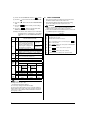
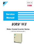
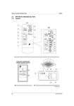
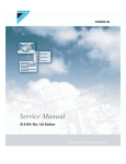
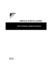
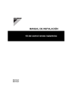
INSTALLATION MANUAL
Wireless Remote Controller Kit
MODELS
BRC7C812
Read these instructions carefully before installation.
Keep this manual in a handy place for future reference.
This manual should be left with the equipment owner.
Wireless Remote Controller Kit
CONTENTS
1.
2.
3.
4.
5.
6.
1.
SAFETY CONSIDERATIONS.......................................... 2
BEFORE INSTALLATION ................................................ 2
REMOTE CONTROLLER INSTALLATION ...................... 2
RECEIVER INSTALLATION............................................. 3
FIELD SETTING .............................................................. 4
TEST OPERATION.......................................................... 5
SAFETY CONSIDERATIONS
Please read these “SAFETY CONSIDERATIONS” carefully
before installing air conditioning equipment and be sure to
install it correctly. After completing the installation, make sure
that the unit operates properly during the start-up operation.
Please instruct the customer on how to operate the unit and
keep it maintained.
Also, inform customers that they should store this installation
manual along with the operation manual for future reference.
This air conditioner comes under the term “appliances not
accessible to the general public”.
Installation manual
• The installation position of this receiver is one corner of
the decoration panel. Therefore, confirm that its position
is set so that the signal from the wireless remote controller can be easily transmitted and its display can be easily
seen.
• If both this kit and fresh air intake kit are installed, only
one duct chamber shall be used. Refer to the installation
manual of the fresh air intake kit (optional hand book).
2.
2-1
BEFORE INSTALLATION
ACCESSORIES
Check if the following accessories are included with the unit.
Name
(1) Receiver
Quantity
1 set
(2) Wireless
(3) Remote
remote controller
controller holder
1 pc.
1 pc.
Shape
Meaning of warning, caution and note symbols.
WARNING ............. Indication a potentially hazardous situation which, if not avoided, could
result in death or serious injury.
CAUTION .............. Indication a potentially hazardous situation which, if not avoided, may
result in minor or moderate injury. It
may also be sued to alert against
unsafe practices.
NOTE .................... Indication situation that may result in
equipment or property-damage-only
accidents.
WARNING
• Perform installation work in accordance with this installation manual.
Improper installation may result in electric shocks or fire.
• Be sure to use only the specified accessories and parts
for installation work.
Failure to use the specified parts may result in, electric
shocks, fire or the unit falling.
• Before touching electrical parts, turn off the unit.
• Do not touch the switch with wet fingers.
Touching a switch with wet fingers can cause electric shock.
Name
Quantity
Name
Quantity
• Refer also to the installation manuals attached to the
indoor unit and the decoration panel.
• Confirm that the following conditions are satisfied prior
to installation.
Ensure that nothing interrupts the operation of the wireless
remote controller. (Ensure that there is neither a source of
light nor fluorescent lamp near the receiver. Also, ensure that
the receiver is not exposed of direct sunlight.)
Ensure that the operation display lamp and other indicators
are easy to see.
(5) Unit No. label
2 pcs.
1 pc.
1
1
1
Shape
(7) Operation
manual
1 pc.
2
2
2
2 pcs.
3
3
3
(8) Installation
manual
1 pc.
(6) Screw for installing
remote controller
holder
(9) Sealing pad
1 pc.
Shape
Name
Quantity
(10) Clamp
1 pc.
Shape
2-2
CAUTION
(4) Dry cell battery
LR03 (AM4)
NOTE TO THE INSTALLER
Be sure to instruct the customer how to properly operate the
system showing him/her the attached operation manual.
3.
REMOTE CONTROLLER INSTALLATION
<Installing wireless remote controller>
• Do not throw the remote controller or impose large shocks.
Also, do not store where it may be exposed to moisture or
direct sunlight.
• When operating, point the transmitting part of the remote
controller in the direction of the receiver.
2
• The direct transmitting distance of the remote controller is
approximately 23 ft..
• The signal cannot be transmitted if something such as curtains blocks the receiver and the remote controller.
• Installing to a wall or a pillar
1. Fix the remote controller holder (3) with
the screws (6).
CAUTION
Change the setting so that the internal electronic equipments
are not damaged with a pen etc.
When using both a wired and a wireless remote controller
for 1 indoor unit, the wired controller should be set to MAIN.
Therefore, set the MAIN/SUB switch (SS1) of the receiver
to SUB.
MAIN
MAIN/
SUB
switch
(SS1)
2. Slide the remote controller (2) into the
remote controller holder (3) from the top.
SUB
S
S
M
M
After completing setting, seal off the opening of the
address switch and the MAIN/SUB switch with the
attached sealing pad.
• How to put the dry batteries
1. Remove the back cover of the remote controller (2) to the direction pointed by the
arrow mark.
2. Put the dry cell batteries.
Use two LR03<AM4> dry cell batteries (4).
Put the dry cell batteries (4) correctly to fit
their (+) and (–).
3. Close the back cover as before.
4.
4-4. Receiver installation
CAUTION
Be sure to turn off the power before operation.
RECEIVER INSTALLATION
4-1. Preparations before installation
Remove the control box lid and the front grill. See the
installation manual that came with the indoor unit for
details on removal.
4-2. Determination of address and MAIN/SUB remote controller
If setting multiple wireless remote controllers to operate in
1 room, perform address setting for the receiver and the
wireless remote controller. If setting multiple wired remote
controllers in 1 room, change the MAIN/SUB switch of the
receiver.
4-3. Setting procedure
• Setting the receiver
Set the wireless address switch (SS2) on the transmission PC-board (2) according to the table below.
Unit No.
No.1
No.2
No.3
1
1
1
2
2
2
3
3
3
Wireless
address
switch
(SS2)
(1) Detach the swing motor and the diagonally opposite
decoration corner panel. This corner panel piece is not
needed here after. (Refer to (1) in drawing)
<For instructions on attaching / detaching decoration
panels, see the installation instructions provided with
the original panel.>
The receiver (1) cannot be installed anywhere but
in this corner.
3
(2) Pull the relay harness from the receiver (1) up to where
the clamp (10) meets the stopper, as shown above.
(Refer to (2) in drawing)
(3) Install the receiver (1) where the decoration corner
panel was. Proceed in the opposite order in which you
removed the corner panel. (Refer to (3) in drawing)
(4) Fit the relay harness under the tab on the decoration
panel and connect it to connector X24A on the indoor
unit PC board. Bundle the remaining harness with the
included clamp so that it does not droop or get pinched
in the suction grille. (Refer to (4) in drawing)
(5) Attach the lid to the indoor unit's control box and the
suction grille to the decoration panel. (Refer to installation manual of indoor unit.)
4-5. Setting the address of wireless remote controller
(It is factory set to “1”.)
<Setting from the remote controller>
Remote controller
Indoor unit
Multiple setting
Remote control- To control other For other than
on left
ler display
air conditions
and units
A: Standard
All items displayed.
Commands other
than ON/OFF
and temperature
setting accepted.
(1 LONG BEEP
or 3 SHORT
BEEPS emitted)
b: Multi System Operations remain All commands accepted.
displayed shortly (2 SHORT BEEPS)
after execution
4-6. Stick the Unit No. label on the air outlet of the decoration
panel and the back of the wireless remote controller.
ON OFF
TEMP
TIME
Mode
SETTING
(3)
UP
DOWN
FAN
(2)
RESERVE CANCEL
Address
TIMER
Multiple setting
MODE
(4)
SWING
(1)
TEST
(5)
TEST ”
(1) Hold down the “
” button and the “
button for at least 4 seconds to get the FIELD SET
MODE. (Indicated in the display area in the figure at top.)
CAUTION
Set the Unit No. of the receiver and the wireless remote controller to be equal. If the settings differ, the signal from the
remote controller cannot be transmitted.
5.
FIELD SETTING
If optional accessories are mounted on the indoor unit, the
indoor unit setting may have to be changed. Refer to the instruction manual (optional hand book ) for each optional accessory.
ON OFF
(2) Press the “ FAN ” button and select a multiple setting
(A/b). Each time the button is pressed the display
switches between “A” and “b”.
(3) Press the “
UP
” button and “
DOWN
MODE NO.
TEMP
TIME
” button to set the
SETTING
UP
FAN
address.
FIELD SET MODE
(3)
(4)
DOWN
(5)
RESERVE CANCEL
TIMER
Address can be set from 1 to 6, but set it from 1 to 3 and
to same address as the receiver. (The receiver does
not work with address from 4 to 6.)
(4) Press the “
RESERVE
MODE
SECOND CODE NO.
FIRST CODE NO.
SWING
” button to enter the setting.
TEST ” button to quit the FIELD SET
(5) Push the “
MODE and return to the normal display.
<Multiple settings A/b>
When the indoor unit is being operating by outside control (central remote controller, etc.), it sometimes does not respond to
ON/OFF and temperature setting commands from this remote
controller. Check what setting the customer wants and make the
multiple setting as shown below.
TEST
(2)
(1) (6)
Procedure
TEST ” but(1) When in the normal mode, press the “
ton for at least 4 seconds, and the FIELD SET MODE is
entered.
4
(2) Select the desired MODE NO. with the “
(3) Push the “
(4) Push the “
NO..
(5) Push the“
are set.
UP
MODE
” button.
” button and select the FIRST CODE NO..
DOWN
” button and select the SECOND CODE
RESERVE
(Example) If the time to clean air filter is set to “Filter Contamination-Heavy”, set Mode No. to “10”, FIRST
CODE NO. to "0", and SECOND CODE NO. to
“02”.
0
10
DESCRIPTION OF SETTING
Filter Contamination-Heavy/Light
(Setting for spacing time of display Long-life type
time to clean air filter) (Setting for
when filter contamination is heavy,
and spacing time of display time to Standard type
clean air filter is to be halved)
CAUTION
1. Refer to a malfunction code in the installation manual
attached to the outdoor unit if it does not operate.
2. Refer to the installation manual attached to the outdoor unit
for individual operation system types.
Order
Operation
(1)
Open gas side stop valve.
(2)
Open liquid side stop valve.
(3)
Electrify crank case heater for 6 hours.
(4)
Set to cooling with the remote controller and push “ ON/OFF ”
button to start operation.
(5)
Push“
TEST ”button twice and operate in TEST OPERA-
TION MODE for 3 minutes.
(6)
Push“
SWING ”button and confirm its operation.
Spacing time of display time to clean air filter count
(Setting for when the filter sign is not to be displayed)
(7)
Push“
TEST ”button and operate normally.
ON/OFF input from outside (Set to enable starting/
stopping from remote.)
(8)
Confirm its function according to the operation manual.
1
2
Thermostat differential changeover (Set when using
remote controller thermostat sensor.)
4
Air Flow Direction Range Setting
1
Long-life filter type (Setting of filter sign indication time)
3
12
(VRV
system)
13
SECOND CODE NO. NOTE)
FIRST
MODE
CODE
NO.
NO.
0
10
01
Light
Approx.
2,500 hours
Approx. 200
hours
02
Heavy
Approx.
1,250 hours
Approx. 100
hours
03
—
1
Long-life filter
—
3
Display
Do not display
—
12
(VRV
system)
1
Forced OFF input
ON/OFF
—
2
2°F
1°F
—
13
4
Upper
Normal
Lower
—
NOTE
The SECOND CODE NO. is factory set to "01". However, for the
following cases it is set to "02".
• Air Flow Direction Range Setting
Do not use any settings not listed in the table.
For group control with a wireless remote controller, initial settings for all the indoor units of the group are equal. (For group
control, refer to the installation manual attached to the indoor
unit for group control.)
5
TEST OPERATION
• Perform test operation according to the instructions in the
installation manual attached to the indoor unit.
• After refrigerant piping, drain piping, and electric wiring,
operate according to the table to protect the unit.
”button and the present settings
TEST ” button to quit the FIELD SET
(6) Push the “
MODE and return to the normal display.
FIRST
MODE
CODE
NO.
NO.
6.
3P155845-2C EM05A002A
(0504) FS