1
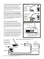
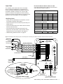
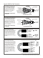
Series 1580
Intercom Systems
THE COMPLETE 1-ON-2 SOLUTION
Installer’s Reference Guide
Series 1580
Intercom Systems
THE COMPLETE 1-ON-2 SOLUTION
WARNINGS
• Read these instructions before installing or using this product.
• To reduce the risk of fire or electric shock, do not expose components to rain or moisture
(except Model 1585 which is designed for outdoor use).
• This product must be installed by qualified personnel.
• Do not open the cover—there are no user-serviceable parts inside.
• Do not expose this unit to excessive heat.
• Install only in dry, indoor locations.
• Clean the unit only with a dry or slightly dampened soft cloth.
LIABILITY STATEMENT
Every effort has been made to ensure that this product is free of defects. Audio Authority cannot
be held liable for the use of this hardware or any direct or indirect consequential damages arising
from its use. It is the responsibility of the user of the hardware to check that it is suitable for his/
her requirements and that it is installed correctly. All rights are reserved. No parts of this manual
may be reproduced or transmitted by any form or means electronic or mechanical, including
photocopying, recording or by any information storage or retrieval system without the written
consent of the publisher.
Audio Authority reserves the right to revise any of its hardware and software following its policy to
modify and/or improve its products where necessary or desirable.
Audio Authority and the Double-A Symbol are registered trademarks of Audio Authority Corp.
Copyright June, 2010. All third party trademarks and copyrights are recognized.
2048 Mercer Road, Lexington, Kentucky 40511-1071 USA
Phone: 859-233-4599 • Fax: 859-233-4510
Customer Toll-Free USA & Canada: 800-322-8346
www.audioauthority.com • [email protected]
2
Audio Authority® Series 1580 Installer’s Reference Guide
Installer’s Reference Guide
Contents
Introduction
Tools and Supplies
Configurations System Configurations
3
Audio Installation
3
Customer Station Setup
System Configuration
Lane Cable Information 5
Cable Types
Wiring Notes
Video Installation
6-8
System Configuration
Wiring Notes
Cat 5 Cable Fabrication
Video Customer Station
Program Audio/Video
Traffic Sensors
Calibration & Testing Calibration
Self-Setup
Troubleshooting 9
Operation
Operator Tips
Operator Guide
10
Audio Authority Series 1580 Intercoms enable clear two-way communication
in retail service businesses. A system comprised of a Model 1580 Counter
Station (without handset) or 1580H (with handset) and a Model 1583 Dual
Lane Station with microphones, speakers, etc. Provides a complete 1-on-1
or 1-on-2 audio solution for drive-up and other customer service applications.
The 1580 Series is not expandable beyond 1-on-2, and cannot be used with
Series 1500 Counter Stations, Lane Stations or Hubs.
One-way or two-way video is easily added by installing a Model 1581 (inbound
only) or 1582 (two-way) Counter Video Add-on and a Model 1584 Video
Matrix. On the customer side, the 1584 supports Audio Authority Model 1585
Customer Audio/Video Stations or third-party video cameras and monitors.
Series 1580 System Components
Counter Audio Station
Counter Audio with Handset
Inbound Video Add-on
Two-way Video Add-on
Dual Lane Station
Video Matrix
Customer Audio/Video Station
1580
1580H
1581
1582
1583
1584
1585
Accessories
Advanced Setup
12
1550 Field Setup Display
Example Configuration
Parameter Definitions
Appendix
15
Multi-pair Cable Termination
Special Tools and Supplies
• 18mm flare nut wrench for
gooseneck mic installation
• Model 1550 Field Setup
Display
• Shielded, paired cable for
Lane Station (drive-ups)
Surface-Mount Customer Handset
Flush-Mount Customer Handset
Wireless Counter Headset
Traffic Sensor
Traffic Sensor Adapter
Field Setup LCD
Universal 1-Amp Power Supply
5-Amp Power Supply for Heated 1585
Gooseneck Counter Microphone
Color Chip Kit
Lane Microphone kit
Lane Speaker (3 in.)
1540
1541
1542
1547
1589
1550
571-013
571-020
631-026
761-311
631-029
631-030
Audio Installation with 1580S or 1580HS Kits
The 1580S Kit consists of one Model 1580, one Model 1583, and a 571-013
power supply. To complete the system, the necessary lane microphones,
speakers, call button switches, and shielded cable for one or two customer
positions or drive-up lanes must be purchased separately. The 1580HS Kit is
exactly like the 1580S, but contains a 1580H Counter Station with a handset.
Figures 3 and 4 show the usual wiring method. After plugging in the main
components as shown, wire each LANE port of the 1583 Dual Lane Station
to its respective microphone, speaker and call button using shielded, paired
cable with an overall shield as shown in the Lane Cable section (page 5).
Mount the 1583 on the wall under the counter, or in some other nearby
location.
Audio Authority® Series 1580 Installer’s Reference Guide
3
Cable from the Lane Station to the speaker, mic, call button,
etc. must be shielded, paired cable (see recommended
cable types on page 5). Four pair, 18 AWG cable is
adequate for most installations. Three-pair cable is
sufficient for two-way audio and call functions, but more
conductors are needed when pneumatic blower motor
operation must be sensed, a traffic sensor is installed, or
the dry relay contacts are used.
Whatever cable is used, it must have an overall foil
shield – the drain wire is connected to the Common (#8)
terminal on each Lane station block. The DRAIN WIRE
on the customer end of the cable must be cut off and
not connected. For proper system operation, one of the
Lane Common terminals must also be connected to a good
ground, such as an electrical box or a metallic structural
member, using the green ground wire supplied. This wire
may be extended if necessary.
Audio Counter Station Assembly
Install the supplied “gooseneck” microphone on the 1580
Counter Station by plugging it into the jack at the rear,
tightening the hex nut and setting the rubber boot over the
nut. If equipped with a handset, plug it into the jack on the
bottom of the 1580, push the coil cord into the notch on
the bottom edge of the housing, and set the handset on its
cradle.
The color chip array under the keypad cover can be rotated
to choose between black and red or yellow and red Lane
keys. To do that, loosen the 4 small screws at the corners
of the keypad cover to remove it and rotate the color chip
array. If other than these colors are desired, carefully break
out the chip(s) that must be changed and replace them
with chips taken from the 12-color chip array (761-311,
purchased separately). Replace the keypad cover and
carefully replace the screws without overtightening.
1580S Kit
Includes 1580
Counter Station,
1583 Dual Lane
Station and 571-013
power supply.
1583
1580
1 on 2 Audio System
with Handset
1580HS Kit
Includes 1580H
Counter Station with
handset, 1583 Dual
Lane Station and
571-013 power
supply.
1580H
1583
Figure 2. Use either the built-in
gooseneck mic, the optional handset,
or a wireless headset.
MICROPHONE BOOT
POWER HEAD
SET
1583
Model 1580
CAT 5/6 UTP
SEE LANE
CABLE DETAIL
COUNTER
STATION
MODEL 1580H
LANE STATION
MODEL 1583
4
1 on 2 Audio System
HANDSET JACK
1583 LANE STATION CONNECTION
WIRELESS HEADSET JACK (MODEL 1542)
AUXILIARY POWER PORT (OPTIONAL)
Figure 3. Typical audio only system with optional handsets installed.
Shielded, paired cable is required for lane wiring as shown.
The counter station power
port is used only when
the 1583 is not near an
AC power outlet, or when
both counter and lane
station must be powered
due to excessive distance
between them.
POWER
SUPPLY
Figure 1. Audio Kits.
Audio Authority® Series 1580 Installer’s Reference Guide
LANE 1
LANE 2
MICROPHONE
MICROPHONE
SPEAKER
SPEAKER
CALL BUTTON
CALL BUTTON
HANDSET
HANDSET
CAT 3 CABLE
SHIELDEDPAIRED CABLE
Lane Cable
Recommended Lane Device Cables for 1583
Use these shielded, paired cables for lane audio and
other devices as shown in Figure 3.
Use shielded, paired cable with three to six twisted
pairs of conductors (depending on configuration) to
connect the Model 1583 Dual Lane Station to the lane
microphone, speaker, call button, etc. Use one pair
each for microphone and speaker, and the remaining
conductors for other functions sharing a common ground
(Figures 3 and 4). See page 15 for more diagrams.
22 GAUGE (50 feet maximum)
BRAND
1583 Wiring Notes
• Always use one twisted pair for microphone, and one
for speaker to maintain audio quality.
3 PAIRS
4 PAIRS
6 PAIRS
Belden
5542FE
5543FE
5545FE
General Cable
C0551A
C0552A
C0553A
Alpha Wire
6418
6419
6420
Consolidated
6703-CL
6704-CL
6706-CL
5343FE
5345FE
18 GAUGE (125 feet maximum)
• Connect the 1583 Common terminal (of one lane) to a
reliable ground.
Belden
• Connect the Drain Wire to the 1583 Common terminal,
and trim at the other end.
• N.O. (Normally Open) Contacts are used for any
device such as a door latch or solenoid that must be
operated from the Counter Station. See page 10.
5342FE
General Cable
C0561A
C0562A
C0563A
Alpha Wire
6428
6429
6430
Consolidated
6753-CL
----
6756-CL
1584A
----
16 GAUGE (250 feet maximum)
Belden
• Handset wiring details are shown on page 15.
1528A
Figure 4. Shielded, paired cable (four-pair in this example) for connecting Lane Station terminals to audio and other lane devices.
MICROPHONE
MODEL 631-029
SPEAKER
MODEL 631-030
12V DC
LANE 1
LANE 2
1+
COMMON
2–
3+
TRAFFIC SENSE
(3RD PARTY)
4–
5
BLOWER MUTE
MICROPHONE
SPEAKER
CALL BUTTON
+1
–2
LEFT
+3
–4
PROGRAM AUDIO
SHIELDED TWISTED PAIR
CALL BUTTON
Model 1583
Dual Lane Station
5
6 TRAFFIC SENSE 6
7
BLOWER
7
8
COMMON
8
9
CUT DRAIN WIRE x
10
HANDSET
N.O. CONTACTS
9
RIGHT
LEVEL
10
HANDSET
GROUND
CAT 3 CABLE
(SEE APPENDIX)
HANDSET
AT LANE
MODEL 1540
OR 1541
DRAIN WIRE
(DO NOT CONNECT
AT THIS END)
POWER
1584
VIDEO
MATRIX
1580
COUNTER
STATION
719-216B
800-322-8346 • 859-233-4599 www.audioauthority.com
CUT
MICROPHONE
SPEAKER
CALL BUTTON
LANE
STATION
COMMON (SHARED)
TRAFFIC SENSE
BLOWER
SHIELD
CUSTOMER DRIVE-UP END
TRAFFIC SENSOR
(MODEL1547)
SEE PAGE 8 FOR DETAILS
PROGRAM
AUDIO
CONNECTIONS
AND LEVEL
CONTROL
CAT 5 CABLE
CONNECTS TO 1580 COUNTER
STATION - MAY BE UP TO 50 FT.
Audio Authority® Series 1580 Installer’s Reference Guide
5
Video Installation with 1581S
or 1582S Kits
Figure 5. Video Kits.
Video may be added to an audio-only system using
these kits, which include a Model 1581 (one-way
video) or 1582 (two-way video), a Model 1584 video
matrix and a 1-amp power supply. A Model 1585
Customer A/V Station or third-party video cameras
and monitors are purchased separately, along with
the necessary Cat 5e/6 or coaxial connecting cable.
One-Way Audio/Video System
1581S Kit
1581
Includes 1581
(one-way) video
add-on and 1584
Video Matrix.
1584
1580S Kit
Assemble the 1581 or 1582 Video Add-on to the
rear of the 1580 Counter Station base using the
two screws furnished and tighten them securely.
Loosen the adjustment knobs on the support
column to adjust the angle and height of the video
head.
Includes 1580
Counter Station
and 1583 Dual
Lane Station.
1583
1580
Mount the 1584 on the wall near the 1583 Dual
Lane Station and connect it to the 1581 or 1582
Counter Video unit and the 1583. Connect the
remaining lane video cameras, monitors, and/or
Model 1585 Customer Stations to their respective
ports on the 1584. When preparing Category 5
cable for Model 1585 video connections, be careful
to correctly assign the 8 wires to each modular plug
using EIA 568B specifications. See the wiring guide
on page 15.
Two-Way Audio/Video System
1582S Kit
1582
Includes 1582
(two-way) video
add-on and 1584
Video Matrix.
1584
1580HS Kit
Includes 1580H
Counter Station
and 1583 Dual
Lane Station.
1580H
1583
Figure 6. Video configuration with handset on Lane 2. See page 15 for handset cable termination. Always use shielded, paired cable
for lane audio, call button, etc.
LANE 2
AUDIO / VIDEO
COUNTER
STATION
1582S
LANE 1 AUDIO
1585
(HEATED)
MICROPHONE
SPEAKER
CALL BUTTON
1580H
1583
CAT 5/6 UTP
CAT 5/6 UTP
1584
LANE 1 VIDEO
RG-59 CABLES
CAMERA
MONITOR
CAT 5/6 UTP (VIDEO CABLE)
CAT 5/6 UTP
SHIELDED TWISTED PAIR (AUDIO CABLE)
CAT 3 CABLE (HANDSET CABLE)
SHIELDED TWISTED PAIR (AUDIO CABLE)
6
571-020*
Audio Authority® Series 1580 Installer’s Reference Guide
* The 5-amp 571-020
power supply is included
with 1585 units that
have a heater installed.
1541
HANDSET
(PURCHASED
SEPARATELY)
Lane Video Wiring
• See page 15 for Cat 5 cable termination instructions.
• To connect individual monitor and camera use RG-59 with BNC connectors.
• 1585 Customer A/V Station: connect Cat 5e/6 cable to modular coupler as shown, then tuck inside housing.
• Connect a wide view camera if desired. By default this camera’s output is visible in the camera rotation sequence
when no lane is selected. The system can also be set up to show this camera on the Counter Station monitor at all
times. See Advanced Setup on page 12.
• Program video (if used) requires composite video source. See page 8 for details.
Figure 7. Model 1584
Video Matrix wiring.
Model 1584 Video Matrix
CAT 5
COUNTER STATION
1580H AND 1582
800-322-8346 • 859-233-4599 • www.audioauthority.com
MONITOR
(COMPOSITE
VIDEO)
CAMERA
(COMPOSITE
VIDEO)
COUNTER STATION
RG-59, BNC
CAMERA
MONITOR
RG-59, BNC
LANE 1
CAMERA
MONITOR
DVR
DVR
RG-59, BNC
CUSTOMER A/V
STATION
(MODEL 1585)
CAT 5
1581 / 1582
1585
LANE 2
CAMERA
MONITOR
DVR
POWER
(REQUIRED)
1585
WIDE
VIEW
CAMERA
(COMPOSITE
VIDEO)
12V DC
RCA PATCH CORD
PROGRAM
VIDEO
1583
LANE
STATION
POWER
1583
SOURCE
CAT 5
COMPOSITE VIDEO
Model 1585 Customer Station Installation
Model 1585 Customer Stations accept a Category 5 cable
from a 1584 Video Matrix and a multi-paired cable from
a 1583 Dual Lane Station. Connect pairs of lane cable
conductors to their respective microphone, speaker, and
call button positions on the terminal block inside the 1585.
Additional terminals are provided in the 1585 for control
functions supported by Model 1583.
If a Model 1541 armored handset is being added to the
Model 1585, remove the large knockout on the right side
panel of the 1585 enclosure, mount the 1541 with the
fasteners provided and run a Cat 3 modular cable from
the 1541 to the respective Handset port on the 1583 Dual
Lane Station.
DUAL LANE
STATION
MODEL 1583
CALL BUTTON
CAMERA
MICROPHONE
MONITOR
SPEAKER
Figure 8. Model 1585
Customer A/V Station.
TO 1583
LANE
STATION
1
+
2
–
MICROPHONE
3
+
4
–
SPEAKER
5
6
7
8
CALL TRAFFIC BLOW COMMON
SENSE MUTE
9
10
N.O.
CONTACTS
Figure 9. Terminal block inside 1585 for connecting 1583 shielded
cable devices. Video display, camera and handset are wired separately.
Audio Authority® Series 1580 Installer’s Reference Guide
7
Program Audio/Video Connection
If audio or video program content will be playing at the customer positions when lane stations are on HOLD or idle, plug
the source player or PC into the Program Input ports on the 1583 and 1584, respectively. Program audio level may be
manually adjusted on the 1583. One lane’s program audio may be turned off during idle periods (still heard while on
HOLD) using the 1550 Program Audio Abate setting (see page 14).
DVD PLAYER
(COMPOSITE VIDEO)
AUDIO
AUDIO
1584
1583
COMPOSITE VIDEO
LEVEL CONTROL
LEVEL CONTROL
1584
1361
If the program video source
is a PC, either a composite
video card or external converter
is required. Audio Authority
Model 1361 is an ideal adapter
to convert VGA to composite
video.
COMPOSITE VIDEO
12V DC
Model 1583
Dual Lane Station
LANE 1
LANE 2
Using Third Party Traffic Sensors
1+
The 1583 Dual Lane Station provides a contact for
third party traffic sensing devices (Pin 6). Connect
the device to pin 6 and the common ground wire
(Pin 8).
3+
2–
4–
5
5
7
8
COMMON
8
9
N.O. CONTACTS
9
800-322-8346 • 859-233-4599 www.audioauthority.com
1584
VIDEO
MATRIX
POWER
1580
COUNTER
STATION
FLASH
PORT
MODEL 1547
LANE 1
1547 CABLE
CAT 5 EXTENSION
LANE 1
LANE 2
IN-LINE COUPLER
Audio Authority® Series 1580 Installer’s Reference Guide
AC POWER
1549 CABLE
RIGHT
LEVEL
10
HANDSET
MODEL 1589
ADAPTER
8
LEFT
–4
BLOWER
HANDSET
The 1583 Dual Lane Station provides a connection for
Audio Authority’s Model 1547 traffic sensors. One or
two 1547 sensors may be connected to the 1583 flash
port, located on the end panel, via the 1589 adapter as
shown. When a vehicle triggers the 1547, the Counter
Station generates a call tone for the corresponding lane
to alert the operator. To extend a traffic sensor, use an
in-line coupler and a length of Cat 5 cable as shown.
1547 CABLE
CALL BUTTON
–2
+3
7
10
MODEL 1547
LANE 2
SPEAKER
+1
6 TRAFFIC SENSE 6
+
3RD PARTY TRAFFIC SENSOR –
Using Model 1547 Traffic Sensors
MICROPHONE
PROGRAM AUDIO
1583
Figure 9. Connect a stereo audio
source to the 1583 and/or an A/V
source to 1583 and 1584 using
composite video.
VGA
PC
(VGA OUTPUT)
Basic Calibration and Testing
Troubleshooting Tips
Check the following locations for successful power-up and
connections, indicated as follows:
• ALWAYS test Cat 5 or other UTP cables with a cable
tester – even pre-made cables
• 1580/1580H Counter Station: After boot-up, all lights are
dark until a lane or Privacy mode is selected.
• In case of unexpected performance, restore system
defaults to rule out incorrect system parameters
• 1583 Dual Lane Station: Normal = rapidly flashing green
light (lane selected = solid green light)
• 1583 and 1584 power lights flashing rapidly – indicates
normal connection (solid on indicates a lane is selected)
• 1584 Video Matrix: Normal = rapidly flashing green light
(lane selected = solid green light)
• 1583 or 1584 power light blinks every three seconds –
Indicates problem with system interconnects
• Check the voice channels by selecting each lane and
speaking with an assistant at the customer locations.
Adjust Lane Microphone and Speaker gains using the
Model 1550 Field Setup Display (see page 12 and 13).
Video systems only:
• Touch Camera Up and Down (while lane is selected) to
check Lane Camera tilt.
• Touch Mirror to view Counter Station camera image
(operator view).
• Touch and hold Mirror for three seconds to view
program video and hear program audio.
Acoustical Coupling (Feedback)
• Increase separation of lane microphone and speaker
• Isolate lane microphone and speaker with sounddamping barrier (i.e. foam rubber)
• Mount lane speaker and microphone on separate
surfaces or adjust their mounting angles
• Adjust inbound, outbound or open loop gain levels
(requires 1550)
Audible Hum
• Connect 1583 terminal #8 to a good ground
The Deal Drawer Doesn’t Sound Right
Self-Setup Mode Adjustments
Some operating features are adjusted using the 1580’s
self-setup mode (see below). Advanced setup features
require the 1550 Field Setup Display. See page 12 for
advanced setup.
Touch and hold the Setup key (without a 1550 connected).
The lights next to Camera Up/Down and Volume Up/Down
keys illuminate.
• Touch Camera Up and Down to select one of 16
ringtones.
• Touch Volume Up and Down to set ring volume.
• Select Privacy (light comes on) and touch Volume Up or
Down to set handset and/or wireless headset volume.
• If further handset transmit or receive volume adjustment
is needed, use TX and RX knobs on the underside of
the 1580 Counter Station (Figure 11).
• Fill hollow cavities in the deal drawer with foam rubber
sheets or blocks
• Do not rest Counter Station directly on deal drawer
No Inbound / Outbound Video or Poor Video Quality
• Check Cat 5 cables - consistently use EIA 568A or
EIA 568B standard cable termination (see page 15)
• Check video connectors on 1584 and source if fieldterminated coax cables are used.
Lane Keys Don’t Respond
• Keys not assigned to Counter Station – reassign keys or
restore factory defaults in configuration menu
Counter Station Lights Remain in ‘Burn in’ Pattern
• Check Cat 5 cable - consistently use EIA 568A or
EIA 568B standard cable termination (see page 15)
Lane Microphone Doesn’t Work
• Ensure microphone is electret condenser type
Figure 11.
• Check microphone wiring for correct polarity
• Check Cat 5 cables - consistently use EIA 568A or
EIA 568B standard cable termination (see page 15)
RX=Inbound
Handset Audio
• Ensure Cat 5 cables are connected to correct ports
TX=Outbound
Handset Audio
Wind Noise
1580 COUNTER
STATION
(UNDERSIDE)
Wind noise can often be eliminated by putting a small plug
of 3M Scotchbrite™ material in the microphone opening.
The Audio Authority® lane microphone has a special
foam surround; for optimum results, use Audio Authority
microphones (631-029) and speakers (631-030).
Audio Authority® Series 1580 Installer’s Reference Guide
9
Operation
The 1580 Series Intercom is operated via
touch-sensitive keys on the Counter Station
keypad, shown below. Tasks such as
answering a customer call, ending a call, and
putting a customer on HOLD are shown on
the Operator Guide (page 11) which should be
kept near the Counter Station for reference.
Figure 12. Counter
Station Keypad.
LANE KEYS
Lane 1 and Lane 2, represented by colors, are located here by default.
CAMERA UP
AND DOWN
If video is installed,
aims the lane camera
higher or lower.
VOLUME UP AND DOWN
Customer’s voice becomes
louder or softer in Counter Station
speaker or earpiece of headset
and handset.
MIRROR
When two-way
video is installed, use
MIRROR to aim the
Counter Station camera
on operator.
HOLD
Place a Lane on HOLD. If program
audio/video is installed, the
customer hears music or other
messages. Touch the Lane Key to
resume contact. Touch and hold
the HOLD key to operate a relay
(see below).
SETUP
Choose ringtones and
ring volume. Choose
handset/headset
volume See Self-Setup
Mode on page 8.
PRIVACY
The privacy key is used to switch
from the speaker and gooseneck
PRIVACY LIGHT
mic to the wireless headset. It is
Comes on when wireless
headset or handset is active. not used with the handset.
Operating Remote Devices
The 1580 can be wired to operate a latch or door in a remote location via the keypad. The system can be set up to be
operated in two different ways; consult your technical support provider for details.
• Option 1: Any time the lane is selected the remote device is active (e.g. a door opens).
• Option 2: When a lane is active, the operator touches and holds the HOLD key to activate the device (e.g. hold the
door open). The HOLD key operates normally when touched briefly.
Using a Wireless Headset or Handset
The 1580 and 1580H switches between the built-in speaker and gooseneck microphone, the 1580H handset, and an
optional wireless headset. Some examples of using these communication methods are listed below. Always deactivate
the wireless headset between customer interactions to increase battery life.
Answering a Call
• Speaker/gooseneck mic: Touch the rapidly flashing lane key.
• Handset: Pick up the handset. The first calling lane is automatically selected.
• Wireless headset: Activate the headset, touch PRIVACY and select the flashing lane. If the headset is the preferred
method, leave PRIVACY on.
Putting a Call on HOLD
• Speaker/gooseneck mic: Touch the lane key.
• Handset: Hang up the handset. The calling lane is automatically placed on HOLD.
• Wireless headset: Touch HOLD.
Picking Up a Call from HOLD
• Speaker/gooseneck mic: Touch the blinking lane key.
• Handset: Touch the blinking lane key and pick up the handset.
• Wireless headset: If PRIVACY is already on, activate the headset and select the blinking lane key.
10
Audio Authority® Series 1580 Installer’s Reference Guide
OPERATOR GUIDE
Audio Authority Series 1580 Counter Station
Green Lane Key Lights
Flashing (Rapidly) = Customer calling
On = Customer in 2-way contact
Blinking (Slowly) = Customer placed on HOLD
Counter Station
•
•
•
•
•
•
•
•
•
Operation Tips
• Speak naturally into the microphone at a
distance of about two inches
• Touch keys with the pad of your finger
• Video: Press MIRROR to center your image
in the lane display
To contact a customer calling ...........................Touch LANE key or pick up handset (1580H only)
To place a customer on HOLD .........................Touch the HOLD key or hang up handset (light blinks)
To contact a customer on hold .........................Touch the LANE key
To end contact with customer...........................Touch the active LANE key
To cancel hold and end contact........................Touch the LANE key twice
To talk over a customer ....................................Touch and hold the active LANE key
To adjust incoming volume ...............................Touch VOLUME UP or VOLUME DOWN key
To enter/exit PRIVACY (headset) mode...........Touch the PRIVACY key
To activate remote relay ...................................Touch and hold the HOLD key (30 seconds max)
Wireless Headset
• To use a wireless headset, touch PRIVACY, activate the headset, and select the flashing lane key
• If the headset is the preferred method, leave PRIVACY on
• To increase headset battery life, deactivate the headset between customer interactions
Handset
• To answer a call, pick up the handset, the first calling lane is automatically selected
• To place a customer on HOLD, hang up the handset
• To speak to a customer on HOLD, pick up the handset and touch the lane key
Counter Station Video
•
•
•
•
•
•
To adjust outside camera on selected lane ......Touch CAMERA UP or CAMERA DOWN key
To view yourself (to aim camera)......................Touch MIRROR key (30 second time-out)
To view outgoing video program.......................Hold MIRROR key 3 seconds (no lane selected)
To pause lane camera scrolling ........................Touch HOLD key (no lane selected)
To view next lane camera.................................Touch CAMERA UP key (no lane selected)
To view previous lane camera ..........................Touch CAMERA DOWN key (no lane selected)
Adjust Ringtones and Ringer Volume
• Touch and hold the SETUP key until lights next to CAMERA and VOLUME keys blink
• Touch CAMERA UP and DOWN to select one of 16 ringtones
• Touch VOLUME UP and DOWN to set ringer volume
Adjust Counter Station Handset Volume (1580H)
• In SETUP MODE, touch PRIVACY and press VOLUME UP or DOWN
• If further handset transmit or receive volume adjustment is needed, contact your technical support
provider
2048 Mercer Road, Lexington, Kentucky 40511-1071
Phone: 859-233-4599 • Fax: 859-233-4510
Customer Toll-Free USA & Canada: 800-322-8346
www.audioauthority.com • [email protected]
752-601
2/10
Audio Authority® Series 1580 Installer’s Reference Guide
11
Advanced Calibration and Setup
Figure 13. 1550 Field Setup Display
Using the 1550 Field Setup Display
The Model 1550 is a device that displays and enables the advanced setup
menus and settings for Series 1500/1580 Intercom Systems. (Touching
SETUP without the 1550 activates basic SETUP MODE.) Connect the
1550 Field Setup Display to the RJ-45 jack on the underside of the
Counter Station. (The jack is at an angle, located near the right front edge
of the Counter Station.) Upon connection, the 1550 displays “SERIES
1500 EQUIPMENT CALIBRATION PLATFORM”.
SERIES
1
EQUIP 500
ME
CALIBRNT
AT
PLATF ION
ORM
CAT 5E/6
RECESSED
JACK
(ANGLED)
Figure 14. Using the Keypad for Setup Navigation.
CAMERA = Select next
or previous lane (after
selecting a single lane,
or autoselect 1 lane)
SETUP = Enter or
confirm selection
1580 COUNTER STATION (UNDERSIDE)
Setup Mode Operation
• Hold the SETUP key on the Counter
Station for one second to enter Setup
Mode. The 1550 displays the top level
of the menu.
Setup Menu Map
• To navigate the menus, use the
VOLUME UP and VOLUME DOWN
keys to move the cursor.
1:SYSTEM PARAMETERS
• Use SETUP to enter a submenu or
confirm a selection, and PRIVACY to
save and exit a submenu.
• Any changes you make are recorded
as you exit each menu. When you
exit Setup Mode, you must choose
to either save all changes and exit or
exit without saving.
• If you need to re-enter Setup Mode,
simply touch SETUP for 1 second.
Power User Tips
• To Exit Setup Mode from any menu,
hold SETUP for one second and
follow the prompts on the 1550.
• After adjusting a Lane Station or
Counter Station, use the CAMERA
UP or CAMERA DOWN keys to select
other stations for adjustment without
leaving the submenu.
12
1:BLOWER MOTOR DELAY
2:POWER SAVE DELAY
3:LN MIRROR DISABLE
4:TRAFFIC SENSOR TONE
5:BACKGRND THRESHOLD
6:ALLOW VIDEO SCROLL
2:LANE PARAMETERS
1:SINGLE LANE *
2:AUTO-SELECT 1 LANE *
3:ALL LANES
4:CANCEL
3:TELLER PARAMETERS
1:KEY ASSIGNMENT
2:ALLOW HANDSFREE
4:SET DEFAULTS
1:CANCEL
2:FACTORY DEFAULTS
5:EXIT
1:CANCEL
2:EXIT AND SAVE
3:EXIT WITHOUT SAVING
1:INBOUND VOLUME LVL
2:OUTBOUND VOLUME LVL
3:OPEN LOOP GAIN
4:HANDSET MIC LVL
5:HANDSET SPKR LVL
6:RINGTONE OVERRIDE
7:HALF DUPLEX ONLY
8:PROGRAM AUDIO ABATE
9:RELAY OPERATION
* LANE PARAMETERS: There is a lane selection menu between the
menus pictured. Select SINGLE LANE, or AUTO-SELECT 1 LANE
and touch SETUP. Select the desired lane, and touch SETUP to make
adjustments to that lane. Touch PRIVACY to save and exit.
Audio Authority® Series 1580 Installer’s Reference Guide
Advanced Configuration Example
To enter the configuration menu, connect a 1550 Field Setup Display to the underside of the 1580 Counter Station, then
touch and hold the SETUP key for one second.
Adjust Audio Levels
1. Select 2:LANE PARAMETERS
2. Select 2:AUTO-SELECT 1 LANE
3. Select Lane 1 or 2.
3. Touch SETUP to confirm
a. Set inbound audio level
i.
Select 1:INBOUND VOLUME LVL
ii. Use VOLUME keys to raise or lower inbound volume
iii. Touch PRIVACY key to return
b. Set outbound audio level
i.
Select 2:OUTBOUND VOLUME LVL
ii. Use VOLUME keys to raise or lower outbound volume
iii. Touch PRIVACY key to return
c. Adjust open loop gain
i.
Select 3:OPEN LOOP GAIN
ii. Use VOLUME keys to raise or lower open loop gain
iii. Touch PRIVACY key to return
d. Touch CAMERA UP/DOWN keys at any time to adjust next/previous lane station
Configure Key Assignment
1. Select 3:TELLER PARAMETERS
2. Touch SETUP
3. Select 1:KEY ASSIGNMENT
a. Use VOLUME keys to select lane to be assigned
b. Touch any lane key to assign selected lane to that key
Exit Setup
a. Hold SETUP for one second to jump to EXIT menu at any time
b. Select 2: EXIT AND SAVE
c. Touch SETUP to exit
Audio Authority® Series 1580 Installer’s Reference Guide
13
Setup Definitions
14
BLOWER MOTOR DELAY
When enabled, and blower mute connections are installed, this is the period between
disengagement of the blower and microphone audio un-mute.
POWER SAVE DELAY
When enabled, this is the length of time the system must be idle before entering
Power Save (LCD sleep).
LANE MIRROR DISABLE
OFF = idle Lane Stations display their own camera output.
ON = idle Lane Stations DO NOT display their own camera output. Customers see a
blank screen or program video, if installed.
TRAFFIC SENSOR TONE
Touch a key to select a unique ringtone for all traffic sensor events.
0 = no ringtone, 1 = use Lane Station Ringtone Override setting.
BACKGRND THRESHOLD
Adjustment for level of background audio that is rejected by Counter Station
microphone.  0 = no rejection.
ALLOW VIDEO SCROLL
Counter Station monitor rotates between lane camera views and wide angle camera
when no lane is active.
SINGLE LANE
Use this mode to configure lane without live audio. Useful when lanes are in use or
audio is not required for adjustments.
AUTO-SELECT 1 LANE
Use this mode to configure lane with live audio (using an assistant at the Lane
Station). Useful for adjusting inbound and outbound audio levels.
INBOUND VOLUME LVL
Adjust volume level of customer’s voice heard at the Counter Station.
OUTBOUND VOLUME LVL
Adjust volume level of operator’s voice heard at the Lane Station.
OPEN LOOP GAIN
Adjustment for adapting to different acoustic environments. Lower this setting for
Lane Station acoustical environments with too much microphone and speaker
coupling. Increase this setting to hear more of the customer while operator is talking.
HANDSET MIC LVL
Inbound handset volume level adjustment (customer’s voice).
HANDSET SPKR LVL
Outbound handset volume level adjustment (operator’s voice).
RINGTONE OVERRIDE
Touch a key to select a unique ringtone for the selected Lane Station(s).
1 = no override (plays the ringtone set by the Counter Station).
All other keys represent unique ring tones which override any Counter Station
settings.
HALF DUPLEX ONLY
Enables ‘push-to-talk’ operation, useful for high background noise locations.
PGM AUDIO ABATE
ON = Program Audio heard ONLY when lane is on hold.
OFF = Program Audio heard when lane is idle OR on hold
RELAY OPERATION
Allows configuration of 1583 relay contacts (terminal block positions 9 & 10). The
contacts can be set to close using the HOLD key (touch and hold operates the relay),
or while the lane is selected. (See Operator Guide for HOLD key operation details.)
KEY ASSIGNMENT
This menu enables lane selection keys to be redefined in any configuration desired.
First select the lane number to be assigned using the VOLUME keys. Then touch the
key to be assigned to that lane.
FIRMWARE UPGRADE
This menu is used to update the firmware of system components. Call Audio Authority
Technical Support for details.
Audio Authority® Series 1580 Installer’s Reference Guide
Appendix: Multi-Pair Cable Termination
DRAIN WIRE
(DO NOT CONNECT
AT THIS END)
Lane Wiring, Five Devices
Use 4-pair shielded, paired cable
for up to five devices. See page 5
to determine the required gauge.
Always use one pair for mic (+ / –)
and speaker (+ / –). The other
devices share a common.
ALWAYS TRIM THE DRAIN WIRE
AT THIS END.
MICROPHONE
SPEAKER
CALL BUTTON
DUAL LANE
STATION
COMMON (SHARED)
TRAFFIC SENSE
BLOWER MUTE
SHIELD
CUSTOMER DRIVE-UP END
Lane Wiring, Three Devices
Use 3-pair shielded, paired cable
for up to three devices. See page
4 to determine the required gauge.
Always use one pair for mic (+ / –)
and speaker (+ / –). The other pair
can be used for blower mute, traffic
sensor, or call button.
DRAIN WIRE
(DO NOT CONNECT
AT THIS END)
(For 1540 or 1541 Lane Handset)
DUAL LANE
STATION
SPEAKER
CALL BUTTON
SHIELD
CUSTOMER DRIVE-UP END
1 - WHITE/GREEN
2 - WHITE/ORANGE
HANDSET
3 - BLUE
JACK
4 - WHITE/BLUE
5 - ORANGE
1 - WHITE/GREEN
6 - GREEN
2 - WHITE/ORANGE
3 - BLUE
4 - WHITE/BLUE
5 - ORANGE
1 - GREEN
DUAL LANE
6 - GREEN
2 - ORANGE
Cat 3
For customer handsets use 3-pair
Category 3 cable. Terminate at each
end with an RJ-12 plug (sometimes
referred to as RJ-25). One end is
terminated opposite (mirror image) to
the other.
Cat 5 Cable Fabrication
Cat 5e or Cat 6 is UTP (Unshielded
Twisted Pair) cable that can be used
to connect Series 1580 components
except for locations where shielded
twisted-pair cable is required.
Terminate the ends of each Cat 5e/6
cable with RJ-45 modular plugs
using the EIA 568B pinout (paired
1-2, 3-6, 4-5, and 7-8). Pre-made
network cables may also be used
for shorter runs. TEST all cables
(including pre-made) with a network
cable tester.
CUT DRAIN WIRE
MICROPHONE
ALWAYS TRIM THE DRAIN WIRE
AT THIS END.
Cat 3 Cable Fabrication
CUT DRAIN WIRE
STATION JACK
3 - WHITE/BLUE
(OPPOSITE
4 - BLUE
PINOUT)
5 - WHITE/ORANGE
1 - GREEN
6 - WHITE/GREEN
2 - ORANGE
3 - WHITE/BLUE
CABLE WIRED OPPOSITE ON ONE END (CROSSED OVER).
4 - BLUE
5 - WHITE/ORANGE
1 WHITE / ORANGE
6 - WHITE/GREEN
2 ORANGE
RJ-45 plug with pins facing up
clip/ facing
3 and
WHITE
GREENaway.
Cat 5e/6
4
5
6
7
8
1
2
3
4
5
6
7
8
BLUE
1 /WHITE
WHITE
BLUE / ORANGE
2 ORANGE
GREEN
3 /WHITE
/ GREEN
WHITE
BROWN
BROWN
4 BLUE
5 WHITE / BLUE
6 GREEN
7 /WHITE
/ BROWN
WHITE
ORANGE
8 BROWN
ORANGE
WHITE / GREEN
BLUE
1 /WHITE
WHITE
BLUE / ORANGE
2 ORANGE
GREEN
3 /WHITE
/ GREEN
WHITE
BROWN
BROWN
4 BLUE
5 WHITE / BLUE
6 GREEN
7 WHITE / BROWN
8 BROWN
CABLES ARE WIRED THE SAME ON BOTH ENDS (NOT CROSSED OVER).
Audio Authority® Series 1580 Installer’s Reference Guide
15
2048 Mercer Road, Lexington, Kentucky 40511-1071 USA
Phone: 859-233-4599 • Fax: 859-233-4510
Customer Toll-Free USA & Canada: 800-322-8346
www.audioauthority.com • [email protected]
752-593
6/10