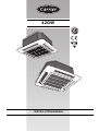
1
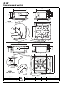
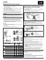
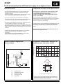
R QUALIT
TE
SURANC
E
AS
•
L
INSTALLATION MANUAL
Y
YD'S REGI
S
LO
42GW
IS O
900 1
Contents
Page
Dimensions and weights ........................................................................
2
Technical data ........................................................................................
3
General information ...............................................................................
4
Avoid ......................................................................................................
5
Installation .............................................................................................
6/8
Water connections .................................................................................
8
Motorized valve and control ...................................................................
9/11
Electrical connections ............................................................................
11/12
Wiring diagram .......................................................................................
13
Fresh air renewal and conditioned air supply to adjacent room ............
14/15
Maintenance ..........................................................................................
16
Models
C = 2-pipe
D = 4-pipe
Models
C = 2-pipe
D = 4-pipe
Models
with
electric heater
42GWC004
42GWC004H
42GWC008
42GWC008H
42GWC010
42GWC010H
42GWC012
42GWC012H
42GWC016
42GWC016H
42GWC020
42GWC020H
42GWD004
42GWD004H
42GWD010
42GWD010H
42GWD020
42GWD020H
42GWE004
42GWE008
42GWE010
42GWE012
42GWE016
42GWE020
42GWE004H
42GWE008H
42GWE010H
42GWE012H
42GWE016H
42GWE020H
42GWH004
42GWH008
ENGLISH
42 GW
“Hydronic Global Cassette” Fan Coil Units
Power supply
230V ~ 50Hz
GB - 1
42 GW
Dimensions and weights
575
575
100
90
110
155
160
Ø
Ø
70
158
0
15
225
280
298
120
52
50
720
440
42GW
004 - 008 - 010
515
550
Ø 25
825
825
125
160
88
120
298
237
112
70
ø150
595
150
6 20
42GW
012 - 016 - 020
42GW
Unit
Frame/Grille assembly
GB - 2
960
Ø 25
813
Ø 100
kg
004
17.5
3
008
19
3
010
19
3
012
36
5
016
38
5
020
38
5
42 GW
Technical data
ENGLISH
Table I: Nominal data
POWER INPUT
Models
POWER INPUT
Models
42GWC004
42GWC008
42GWC010
42GWC012
42GWC016
42GWC020
42GWD004
42GWD010
42GWD020
Cooling
W
66
78
100
97
135
197
66
100
197
42GWC004H
42GWC008H
42GWC010H
42GWC012H
42GWC016H
42GWC020H
42GWD004H
42GWD010H
42GWD020H
A
0.28
0.34
0.43
0.42
0.58
0.85
0.28
0.43
0.85
Cooling
W
70
70
65
65
94
123
141
233
70
65
94
123
141
233
Heating
W
56
68
90
87
125
187
56
90
187
42GWE004
42GWH004
42GWE008
42GWH008
42GWE010
42GWE012
42GWE016
42GWE020
42GWE004H
42GWE008H
42GWE010H
42GWE012H
42GWE016H
42GWE020H
A
0.24
0.29
0.39
0.38
0.54
0.81
0.24
0.39
0.81
Note: 230V ~ 50Hz.
Heating
A
0.30
0.30
0.28
0.28
0.40
0.53
0.61
1.00
0.30
0.28
0.40
0.53
0.61
1.00
W
1560
560
2555
555
2584
3113
3131
3223
1560
2555
2584
3113
3131
3223
A
6.8
2.4
11.1
2.4
11.2
13.5
13.6
14.0
6.8
11.1
11.2
13.5
13.6
14.0
Table II: Wire section of connecting cable mm2
Models
L/R
N/C
from 004 to 020
1.0
1.0
• The power cable to the electrical heaters must be type H07 RN-F.
• The unit power cable must be type H07 RN-F.
Table III: Technical data of electric heaters (if installed)
Mod.
004
H004
008
H008
010
012
016
IMPORTANT:
The electric heater must
always be factory installed
(mod. 42GWE/H...).
The use of other eletric
heaters is absolutely
prohibited.
Failure to follow this
safety requirement
causes unit damage and
voids the warranty.
020
Electric heater capacity
Supply voltage (ph)
Max. power input
kW
1.5
0.5
1.5+1.0 0.25+0.25 1.5+1.0
2x1 + 2x0.5
V 230 (1 ph) 230 (1 ph) 230 (*) 230 (1 ph) 230 (*)
400
400
400
A
6.50
2.1
10.8
2.1
10.8
7.5
7.5
7.5
N° 1 Thermostat with automatic reset ST1 60°C
Safety thermostat
N° 1 Thermostat with manual reset(electric) ST2 100°C
Power supply cables
mm2 3 x 1.5 3 x 1.5 3 x 2.5 3 x 2.5
3 x 2.5 5 x 1.5 5 x 1.5 5 x 1.5
Recommended fuse (Type gL)
A
8
8
12
12
12
10
10
10
(*) In areas with a 2 kW limit for single-phase electric heaters it is possible to divide the power supply on two phases and
neutral of a three phase supply with neutral.
Use cable type HO7 RN-F - 4 x 1.5 mm2 - 400V 2N~
Table IV:
Material supplied
Description
Q.ty
Installation instructions
Fresh air intake baffle
1
1
Use
Unit installation
Air renewal
Table V: Operating limits
Water circuit
Water- side maximum pressure
Minimum entering water temperature: + 4°C
1400 kPa (142 m w.c.)
Maximum entering water temperature: + 80°C
Room air
Minimum temperature: 5°C (1)
Maximum temperature 32°C
Power supply
Nominal single phase voltage
Operating voltage limits
Nominal three phase voltage
Operating voltage limits
230V ~ 50Hz
min. 198V – max. 264V
400V 3N ~ 50Hz
min. 342V – max. 462V
60Hz Special Export Market
min. 187V – max. 253V
Notes: (1) If the room temperature can go down to 0°C, it is advisable to empty the water circuit to avoid damage caused by ice (see paragraph
on water connections).
Table VI: Accessories
Description
2-pipe valve
4-pipe valve
Primary air
Air disch. closing
*
Active carbon filter
Electrostatic filter
Drain pan
Size / Code
004-008-010
012-016-020
42GW9003
42GW9004
42GW9005
40GK-900---003-40
40GK-900---002-40
40GK-900---001-40
42GW9009
42GW9007
42GW9008
42GW9006
40GK-900---013-40
40GK-900---012-40
40GK-900---011-40
42GW9010
Description
Water discharge pump
Control
Control
Control
Control
Control CRC
Auxiliary board
Size / Code
004-008-010-012-016-020
40GKX9001
42GW9014
42GW9015
42GW9016
42GW9017
33DFS-RM
42GW9013
* Not to be used on units equipped with electric heater (mod.42GWE)
GB - 3
42 GW
General Information
Unit installation
Choosing the installation site
Read this instruction manual thoroughly before starting
installation.
Positions to avoid:
• This unit complies with the low-voltage (EEC/73/23) and
electromagnetic compatibility (EEC/ 89/336) directives.
• The installation should be carried out by a qualified installer.
• Follow all current national safety code requirements.
In particular ensure that a properly sized and connected ground
wire is in place.
• Check that the voltage and frequency of the mains power supply
are as required for the unit to be installed; the available power
source must be adeguate to operate all other appliances
connected to the same line.
Also ensure that national safety code requirements have been
followed for the main supply circuit.
• Exposure to direct sunlight.
• Areas close to heat sources.
• On damp walls or in positions that may be exposed to water
hazard.
• Where curtains or furniture may obstruct free air circulation.
Recommendations:
• Choose an area free from obstructions which may cause uneven
air distribution and/or return.
• Where necessary, use field-supplied 25 mm I.D. PVC pipe of
appropriate length and with the correct thermal insulation for the
condensate drain extension.
• Consider using an area where installation is easy.
• After installation thoroughly test system operation and explain all
system functions to the owner.
• Look for a position in the room which ensures the best possible air
distribution.
• Use this unit only for factory approved applications: the unit
cannot be used in laundry or steam pressing premises.
• Install unit in a position where condensate can easily be piped to an
appropriate drain.
WARNING:
Disconnect the mains power supply switch before servicing
the system or handling any internal parts of the unit.
• The manufacturer declines any liability for damage resulting
from modifications or errors in the electrical or water
connections.
Failure to observe the installation instructions, or use of the
unit under conditions other than those indicated in Table
"Operating limits" of the unit installation manual, will
immediately invalidate the unit warranty.
• Failure to observe electric safety codes may cause a fire hazard in
the event of short circuits.
• Inspect equipment for damage during transport. In case of
damage file an immediate claim with the shipping company.
Do not install or use damaged units.
• In case of malfunction turn the unit off, disconnect the mains
power supply and contact a qualified service engineer.
• Maintenance must only be carried out by qualified personnel.
• All of the manufacturing and packaging materials used for
this appliance are biodegradable and recyclable.
• Dispose of the packaging material in accordance with local
requiremements.
GB - 4
• Choose a position that allows for the clearances required.
42 GW
Avoid...
MAX 3 m
MAX 3 m
ENGLISH
... any obstruction of the unit air intake or supply grilles.
... exposure to direct sunshine, when the unit is operating in the
cooling mode; always use shutters or shades.
... positions too close to heating sources which may damage the unit.
... exposure to oil vapours.
... connecting condensate piping to sewage system drain without
appropriate trap. Trap height must be calculated according to the
unit discharge head in order to allow sufficient and continuous
water evacuation.
... installation in areas with high frequency waves.
... only partial insulation of the piping.
Non-level installation which will cause condensate dripping.
MAX. 200 mm
... ascending sections of condensate drain piping.
These may only be used near the unit with a maximum height
difference of 200 mm from the top of the unit.
... flattening or kinking the refrigerant pipes or condensate pipes.
... horizontal sections or curves of condensate drain piping with less
than 2% slope.
...slack on electrical connections.
GB - 5
42 GW
Installation
Max. 2 louvres closed
Heating: louvre position for
correct air flow.
Cooling: louvre position for
correct air flow.
Warning: To close one or two air outlets use the special kit
• Install the unit as centrally as possible in the room, the air flow
direction can be controlled by manually regulating the louvres
position, according to the operating mode (cooling or heating): this
will ensure optimum distribution of the air in the room.
• During cooling mode operation the best position for the deflecting
louvres is one which allows air diffusion close to the ceiling
(Coanda effect). In heating mode, the louvres should be
positioned so that the air is directed towards the floor, in order to
prevent layers of hot air forming in the upper part of the room.
If plaster board ceiling panels are installed the maximum
dimensions of the unit housing must not exceed 660 x 660 mm
(mod. 004 - 008 - 010) and 900 x 900 mm (mod. 012 - 016 - 020).
In rooms with high humidity, brackets should be insulated by self
adhesive insulation supplied.
Installation
• In order to allow easy and rapid installation and maintenance,
make sure that in the selected position it is possible to remove
the ceiling panels or, if the ceiling is constructed of masonry,
that access to the unit is guaranteed.
ATTENTION:
Only restrict the air outlets as indicated in the drawing.
Prior to installation
Mark the position of the hangers, connection lines and condensate
drain pipe, power supply cables and remote control cable (see
dimensions); the cardboard template (supplied with the kit) may
be of assistance for this operation. Depending on the type of
ceiling the hangers can be fixed as shown in the drawing.
It is advisable to place the unit as close as possible to the installation site
before removing it from the packaging. The grille panel and the control
are separately packed for maximum protection.
IMPORTANT:
Do not lift the unit by the condensate drain discharge pipe;
hold it by its four corners only.
Unit installation will be facilitated using a stacker.
GB - 6
Nut
Wooden frame
Threaded hangers
Washers
Nut
Washer
Threaded hangers
Washer
Nut
Nut
Once the threaded hangers have been positioned, do not tighten
the nuts, and insert the washers as shown in the drawing.
42 GW
Installation
ENGLISH
Condensate drain pipe
Threaded hangers
"T" bar
(to be removed)
2%
50
First position the connection lines , as described in the chapter
"Water connections".
Remove the "T" bar in order to facilitate installation operations.
Suspension brackets
Carefully lift the unit (without the frame) using the four
suspension brackets (or the four corners), inserting it into the
false ceiling.
If the "T" bar cannot be removed the unit may need to be tilted
(this operation may only be carried out with false ceilings with a
minimum height of 300 mm).
• To ensure correct condensate water flow, the drain pipe should
have a gradient of 2% without obstructions. Furthermore an
odour trap of at least 50 mm depth should be made to prevent
unpleasant odours from reaching the room.
mm
• Condensate may be discharged at a maximum height of 200 mm
above the unit, as long as the ascending tube is vertical and
aligned with the drainage flange.
False ceiling
Spirit level
Align and level the unit by adjusting the nuts and locknuts on
the threaded hangers, maintaining a distance of 25 -30 mm
between the sheet metal body and the underside of the false
ceiling.
Reposition the "T" bar and align the unit in relation to the bar by
tightening the nuts and locknuts.
After connection of the condensate drain line and the refrigerant
lines, carry out a final check to make sure that the unit is level.
• If it is necessary to discharge the condensate from a level
above 200 mm, install an auxiliary water discharge pump and
float valve.
A float valve is recommended to stop the flow switch if there is
a fault at the auxiliary pump.
• The condensate pipe must be insulated with a condensationproof material such as polyurethane, propylene or neoprene of
5 to 10 mm thickness.
• If more than one unit is installed in the room, the drain system can
be made as shown in the drawing.
GB - 7
42 GW
Installation
Frame pre-hooking support
Safety belt
Frame fixing screw
A. Gasket "A"
B. Gasket "B"
A
B
Air discharge
Installation of grille/frame assembly
Carefully unpack the assembly and check for damage sustained in
transit. Attach the assembly to the unit by using the two hooks.
Use the screws supplied to fix the frame in position.
Ensure that the frame is not distorted by excessive tightening,
that it is aligned with the false ceiling and above all that there is
a seal between the air inlet and outlet.
In the drawing gasket "A" prevents return air from mixing with
the supply air and gasket "B" prevents the supply air from
leaking into the ceiling void.
On completion, the gap between the unit frame and the false
ceiling must not be more than 5 mm.
Water connections
Water connections are fixed to the unit body to avoid damage
when pipes are connected; it is advisable to tighten the
connection with a spanner.
It is necessary, when the installation is made, to insulate the
valve and the connection pipes with anti-condensate material
of polyethylene type or expanded neoprene.
The upper coil connection is supplied with an air purge valve,
the lower connection with a water purge valve, suitable for a
10 mm wrench or screw-driver.
(The coil is only partially drainable; it it is advisable to
blow air into the coil for complete drainage).
Checking
Models
Connections
dimension (Ø)
Models
Connections
dimension (Ø)
004
008
010
004 *
010 *
3/4"
3/4"
3/4"
1/2"
1/2"
012
016
020
020*
1"
1"
1"
3/4"
*
Hot water circuits, four-pipe version
Water inlet
Water outlet
Air purge valve
Water purge valve
GB - 8
Before unit operation pour a quantity of water into the external
auxiliary drain pan. Verify that the water flows into the internal
condensate drain pan and that the pump regularly drains the
liquid.
Otherwise check the pipe slope and look for possible
obstructions. Water connections are fixed to the unit body to
avoid damage when pipes are connected; it is advisable to
tighten the connection with a spanner.
42 GW
Motorized valve and control
ENGLISH
• The unit control circuit only allows opening of the motorized
valve when the fan motor is working.
(See wiring diagrams)
Instructions for mounting of motorized
thermo-electric valve assembly
• When the thermostat asks for cooling, terminal 1 of TB3 (cold
water) is supplied with 230V.
When it asks for heating, terminal 2 of TB3 (hot water or
electric heater) is supplied with 230V.
(see "Components" table)
• The control circuit ensures that the condensate discharge
pump works continuously while the thermostat, asking for
cooling, keeps the cold water regulating valve open.
• Insert the clips supplied in the unit side slots.
• The thermo-electric valve must be mounted on the unit after
the unit installation.
For this operation follow figures, depending on model.
WARNING :
The valve is not only necessary to control the room
temperature, but also to stop the cold water flow to the coil
in case of an abnormal condensing water level rise in the
drain pan.
• If there is an abnormal condensing water rise in the drain pan
(for example: possible defective drain, pump malfunction, fan
motor not working) causing the opening of the float switch
contact (FS), the control circuit either operates the c
ondensate drain pump, or at the same time closes the
regulating valve, stopping the cold water flow towards the
coil and avoiding further condensation.
Control
The
• by
as
or
• by
water flow has to be controlled:
installing the motorized thermo-electric valves supplied
accessory
Assembly
For models 42GWD (4-pipe), the valve assembly for the
cold water coil must be installed first.
• Gently grease the O-rings before fitting them into their
seats.
Sizes 004 - 008 - 010
installing motorized field supplied valves.
Motorized thermo-electric valve assembly and components
A
See diagram supplied with
the kit..
D
B C
Ring nut
O-ring
Coil coupling
Sizes 012 - 016 - 020
Adaptor
O-ring
Coil coupling
Fit the reducers and O-rings
towards the coil connection.
D1
F
• Connect the valve assemble to the coil and fix it by a 30Nm
torque.
G
E
• Insulate the valve assembly.
• For 4-pipe hot water coil, repeat all the operations with gas
adaptors, as per the table.
Water inlet
Mod. 42GW
Ref. Description
A
Adaptor 3/4 " gas with O-ring
Adaptor 1" gas with O-ring +
Adaptor 3/4" gas with O-ring +
B
Self tapping screw
C
Clip
D
Valve 1" gas pre-assembled
Valve 1" gas pre-assembled +
Valve 3/4" gas pre-assembled
D1 Valve 3/4" gas pre-assembled
Valve 3/4" gas pre-assembled
Valve 1/2" gas pre-assembled
E
Auxiliary drain pan
F
Insulating material
G Cable holder
• Pass cables through the cable holder G and fix them to the
case using the already pre-assembled screws.
Water outlet
004
012
008
016
010
020
2-pipe
004
010
q.ty
q.ty
q.ty
2
020
4-pipe
q.ty
2+
2
3
3
3
3
1
3
3
3
3
1+
1
1
1
1
1
1
1
1
1+
1
1
1
1
• Mount the drain pan below the valve assembly, inserting the
discharge pipe into the special hole; align and fix it to the 3
clips previously assembled using the three screws supplied.
• Insulate the 3 screws and the drain pan lower part using the
insulating material F.
• To connect the steel pipes to the system, ensure they are
aligned and supported to avoid excess strain on the unit. If
the system is filled with water, check all fitting seals.
NOTE:
The seal efficiency of the valve assembly is factory tested.
Any system losses are therefore due to an incorrect
installation.
Electric connections
1
1
1
• To connect valves to the electric panel pass cables through
the electric panel grommet and connect them to the terminal
board TB3 as per the wiring diagrams.
GB - 9
42 GW
Motorized valve and control
Automatic operation position
Thermo-electric valve
head
Valve body
ON-OFF valves (230V)
• In this case the cold water valve must be controlled by the ONOFF signal from terminal 1 of TB3 and the hot water valve from
terminal 2 of TB3.
ON-OFF valves with other voltages than 230V
• If a room control listed in the accessories table is used, follow
the instructions in the previous paragraph and install two
230V relay at TB3 terminals 1, 2, 4 and 5 which will control
the valve opening.
004 - 008 - 010
012 - 016 - 020
230V valve connection or
230V valve relay connection
Operation of the thermo-electric valve
C
• This 3-way valve is an ON-OFF type with a very slow stroke.
It is not a modulating valve so it has no PTC.
This valve is driven, as a sensible element, by the ambient
thermostat of the “cassette” unit.
H
• The thermo-electric valve is normally closed towards the coil
and open towards the bypass.
When the room temperature does not satisfy the thermostat,
an electric heater activates the heating of a thermostatic
element which causes the down-stroke of the piston; the
valve opens after about 3 minutes about to allow water to
circulate in the coil.
• If the room temperature satisfies the thermostat or if the
electric power has been switched off, the valve is closed after
about 3 minutes towards the coil and is opened towards the
bypass.
• If an emergency occurs, the valve may be manually opened,
removing the electric head, unscrewing the ring nut.
When the emergency ends, remember to reset the valve to
automatic operation, repositioning the electric head;
failure to do this can result in condensate formation due
the water pipes, even if the unit is switched off.
H Heating valve or heating valve relay
C Cooling valve or cooling valve relay
• If a low voltage control is used or if the control is not listed in
the accessories table, the connections must be made on the
unit terminal board.
Control connection
Instructions for field supplied valves
Water connection
• Install valves following manufacturer's instructions; refer to the
relevant figures for connection to the unit.
• Carefully insulate pipes, valve assemblies and coil connections
(cold water side) to avoid condensation forming on the pipes
and dripping on the false ceiling.
Electrical wiring
• Connect the room control following instructions for the control
used.
WARNING:
Pass cables through the control panel cable-conduit.
• Connect valves as per the following instructions, using the
wiring diagram in this chapter.
• Valves, closing the unit water inlet when there is no
power supply, must be used.
GB - 10
Fan speed
H = high speed
M = medium speed
L = low speed
Heat
Cool
42 GW
Motorized valve and control
ENGLISH
• If these connections are not made as described the drain
pan condensate may overflow.
• The water discharge pump should work every time the
cold water valve is opened, supplying TB1 terminal 7 and
8 from TB1 terminal 4.
• Valves should only open when the fan motor is working, i.e.
when one of TB1 terminals 1 or 2 or 3 is supplied from TB1
terminal 4.
• When the system is filled with water, verify all couplings
for tightness.
• The optional electric heater (mod. 42GWE) which can only be
factory installed, must only be energized when the fan is
working.
• The manufacturer does not accept responsibility for the
tightness of the field - installed valve assembly and this
is not tested in the factory. He declines any responsibility
for non functioning of these assemblies and for damage
due to dripping.
• The optional electric heater which must be factory installed on
model 42GWE, works only if TB1 terminals 5-6 are supplied
from TB1 terminal 4.
Electrical connections
We recommend to remove the main board from the electric
panelboard for better access to electric connections.
STANDARD version unit - Control panel
CV
C
C
CG
CP
CV
CG
CP
A
A
B
B
mod. 012 - 016 - 020
mod. 004 - 008 - 010
Capacitor
Ground connection screw
Board
Relay board E-HTR (only on
models with electric heater)
Holes for panel fixing screws
Auxiliary board (accessory)
A. Electric heater supply connection
CV
Fan connector
CG
Float connector
B. Unit power supply connection
CP
Pump connector
C. Polarised connector
GB - 11
42 GW
Electrical connections
The control panel can be reached by opening the grille and
removing the metal covers using the 3 or 4 screws.
IMPORTANT:
• Make ground connection prior to any other electrical
connections.
• If the unit is fitted with an electric heater, this must have a
separate power supply.
Ensure that the mains supply connection is made through a
switch that disconnects all poles, with a contact gap of at least 3
mm.
• Fix the power cable of the electric resistance heaters under the
single cable clamp. Make certain that the YELLOW/GREEN
cable is stripped back further than the others.
IMPORTANT for units with electric heaters;
The unit is equipped with two thermostats: one with automatic
reset and one with manual (electric) reset that can be
reactivated by switching the power supply off and then on.
Connect the power cables to terminal box connectors in
accordance with the wiring diagram and tighten firmly.
Wiring diagram legend
Factory wiring
Low speed
Field wiring
Medium speed
Connector
High speed
Terminal on terminals
Power supply line
Normally closed contact
Heating selection
Normally open contact
Common thermostat (heating)
Cooling selection
Common thermostat (cooling)
Neutral fan
Neutral in
Capacitor
FC
Fan capacitor
FS
Safety switch float
IFM
Fan motor indoor unit
Cables colour
A
Brown
B
Blue
C
Black
G
Grey
R
Red
W
White
Y-G
Yellow/Green
Connections
L
N
Line phase
Neutral
PR
Drain pump relay
PS
Drain pump
Neutral out
C1-3
Connectors
Neutral
HR
Heating relay
Heating out
Warning:
CR
Cooling relay
Cooling out
Any warranty is declined in case of
field changes of factory wiring and
settings
CEV
Electric valve (cooling)
HEV
Electric valve (heating)
PCB
Relay board
Note
HTR
Electric heater
The connection sequence does not
represent the physical lay-out.
ST
T
TB
Safety thermostat
Timer
Terminal board
GB - 12
42 GW
Wiring diagram, standard version unit
햸
햷
햶
햵
햴
햳
햹
햺
Electric heater
supply
230V ~ 50Hz
햻
햽
햲
ENGLISH
04–E / 04–H
1 2 3 4 5 6 7 8 9 10 11
TB1
230V ~ 50Hz
GND
TB2
C
ST2
2
5
4
3
2
1
5
PCB “TB3”
햾
햿
헀
E-HTR
T3
L3
TB3
T2
C HR N
N
PR
ST1
R
C
L2
L
R
1-HTR
T1
HR
ST2
L1
F1
CR
ST1
N
N L
08/10–E / 08-H
230V ~ 50Hz
GND
ST2
R
ST1
R
C
C
ST2
5
6
8
7
9 10
C
B
2
5
PCB “TB3”
G
W
E-HTR
3
4
5
6
2
3
4
5
6
2
5
PCB “TB3”
2
E-HTR
T3
2-HTR
1-HTR
12/16/20–E
FS
400V 3N~ 50Hz
5
4
3
2
1
C
ST2
GND
L2
COOLING ONLY
(2 PIPE SYSTEM)
2
CEV
5
PCB “TB3”
E-HTR
T3
Valves connection:
select the diagram according to the
system type
C HR N
-1-
TB3
ST1
R
C
4-HTR
1
L3
R
L1
FC
R
2-HTR
T2
A
ST2
NRST
2
ST1
N
IFM
3-HTR
T1
PS
1-HTR
12/16/20–E
5
4
3
2
1
GND
L1
HEV
R
ST1
R
C
C
ST2
4-HTR
L2
COOLING+HEATING
(4 PIPE SYSTEM)
L3
-3-
TB3
N
NRST
ST1
CEV
230V 3N~ 60Hz
CEV
C HR N
5
4
3
2
1
COOLING+HEATING
(2 PIPE SYSTEM)
ST2
-2-
TB3
2
5
PCB “TB3”
E-HTR
T3
1
ST1
GND
GND
B
Y-G
C
G
W
C
C
R
Y-G
R
ST2
L1
L2
2
C HR N
2
1
1
T3
C3_F
C3_M
3
3
L3
2
2
ST2
T2
1
1
C
2-HTR
T2
C1_F
C1_M
ST1
R
C
3-HTR
T1
1
2
R
T1
C
C
R
R
Y-G
1
1-HTR
N
NRST
Y-G
C2_M
2-HTR
08/10–E
230V
TAKEN FROM
400V 3N~ 50Hz
C2_F
T2
4
C HR N
3
T1
PCB
CN1
1 2
L3
L2
L1
T
ST1
N
N L
1-HTR
GB - 13
42 GW
Fresh air renewal and conditioned air supply to an adjacent room
105 120
49
B
Ø
C
A
6
21
Ø
A
Model
ØA
mm
B
mm
ØC
mm
004-008-010 012-016-020
150
150
120
120
70
100
Duct connection flange
Clip
6 mm neoprene gasket
Insulated flexible duct
Fresh air intake
Conditioned air supply to an
adjacent room
Polystyrene partition
Baffle
Frame
Air intake grille
Wall
Undercut door
Wall-fitted grille
Door-fitted grille
• Side knockouts allow connection of fresh air inlet ducts and ducts
to deliver conditioned air to an adjacent room.
• Remove the external prepunched anti-condensate insulation and
take away the knockout panels using a punch.
• Use locally purchased material, suitable for operating
temperatures of 60 °C (continuous).
Conduits can be of flexible polyester (with spiral core) or
corrugated aluminium, externally covered with anti-condensate
material (fibre glass of 12 +/- 25 mm thickness).
Air distribution to adjacent room
• To complete the installation, all non-insulated ducts must be
covered with anti-condensate insulation (ex. expanded neoprene,
6 mm thickness).
With a pencil, trace a line on the polystyrene around the inside
edges of the panel that was previously removed.
Cut away the polystyrene with a knife, taking care not to damage
the heat exchange coil.
If these instructions are not observed, condensate may drip;
the manufacturer will not be held responsible for any damage
caused.
Fresh air intake
• The two prepunched side knockouts must not be used at the
same time to deliver conditioned air to an adjacent room.
Remove the polystyrene partition.
Introduce the baffle supplied after the frame has been hooked as
per above figure (ref. ).
Following that tighten the assembly frame/grille using the 4 screws.
GB - 14
• The return and supply duct lengths can be calculated in
accordance with the "air distribution to an adjacent room" and
"fresh air renewal" diagrams (also taking into account the
pressure drop through air diffusers, grilles and fresh air filters),
as well as the increase in noise caused by these ducts.
42 GW
Fresh air renewal and conditioned air supply to an adjacent room
ENGLISH
Fresh air renewal
Conditioned air supply to an adjacent room
• The optional supplementary fan for fresh air intake (field
supplied) has to be connected to terminal block as per
diagrams enclosed.
Fan motor operation is parallel to the thermo-electric control
valve, and the motor stops when the valve shuts off.
• Air supply to an adjacent room requires that the outlet
corresponding with the duct is closed, using the air
supply outlet obstruction kit supplied.
The kit cannot be used in units equipped with electric
heater (mod. 42GWE).
• For winter operation with fresh air intake, an anti-freeze
thermostat set at 2°C is recommended, with the bulb placed
on the water outlet pipe, before the supplementary fan.
• The fresh air flow must be less than 10% of the total air flow,
to avoid operating problems or eccessive noise.
For higher air flow a "primary air kit" is available which uses
the prepunched hole for air ducting to an adjacent room and a
baffle so that the fresh air is introduced into the room through
a diffuser.
• Install an air inlet grille with filter inspection port to prevent
dust and dirt from entering and fouling the unit heat
exchanger.
Filter installation also makes the installation of a duct closing
damper during shut-down periods unnecessary.
An air inlet grille must be fitted (if possible near the floor)
between the air conditioned room (where the unit is situated)
and the adjacent room or, alternatively, the door must be
undercut, as shown in the drawing.
• The duct lengths can be calculated in accordance with the “air
distribution to an adjacent room” diagram, also taking into
account the pressure drop through air diffusers and fresh air
filters.
• DO NOT use active carbon or electrostatic filter kits for
ducts towards adjacent rooms.
Diagram of conditioned air supply to an
adjacent room: one louvre closed
Winter operation diagram with
fresh air intake
Available static pressure - Pa
40
230V ~ 60Hz
TB2
L
N
30
20
010/012
016
10
004
008
020
0
0
100
300
200
410
400
Air flow m3/h
TB3
5
4
3
2
1
Terminal board
Antifreeze thermostat
Speed controller
Fresh air fan motor
Relay 230V
Supply air duct to adjacent room
In case of two louvres closed, the fresh air flow towards the
adjacent room is 50% higher compared with only one louvre
closed (with equal static external pressure)
GB - 15
42 GW
Maintenance and owner's guide
Maintenance
Additional maintenance
Cleaning and maintenance operations must be carried out by
specially trained personnel.
Before performing any service or maintenance operations,
turn OFF the main power switch.
• The electric panel is easily accessible by removing the cover
panel.
The inspection or replacement of internal components such as:
fan motor, coil, condensate discharge pump, float switch, electric
heater (if fitted), involve the removal of the condensate drain pan.
To open the unit grille:
Condensate drain pan removal
• During the removal operation of the condensate drain pan
protect the floor with a plastic sheet under the unit.
• Remove the frame-grille assembly by loosening the screws;
drain the condensate water contained in the drain pan into
a bucket of at least 10 litres capacity, using the special
drain with a rubber plug.
• Remove the electrical panel cover and disconnect the electric
connections, connectors CV, CG, CP and the yellow-green
ground wire (see drawing in “electrical connections”
section).
Turn the two screws through 90° (1/4 turn).
Filter cleaning
Clean filters in accordance with the actual operating
conditions and times (approximately every 6 months).
• The acrylic air filter is washable in water.
Electrostatic and active carbon filters (which can be used on
the unit) are not washable but must be replaced.
• Remove the four fixing screws on the side of the drain pan and
carefully remove the condensate drain pan.
Extract the filter.
Guide for the owner
When installation and tests are completed instruct the Owner on the
main operating modes of the air conditioner, such as:
Acrylic fibre
First vacuum clean the filter, then wash under tap water and
finally dry.
Replace the filter in the correct position.
Prolonged shutdown:
• Before starting the air conditioner:
- clean or replace the unit air filters.
- check and clean the drain pan and the condensate discharge of
the unit
- check tightness of electric connections.
GB - 16
• Turning the unit ON and OFF.
• Changing the operation modes.
• Temperature selection.
Leave the installation manual with the owner for future use during maintenance operations or for any other needs.
L010122H22 - 0405
Via R. Sanzio, 9 - 20058 Villasanta (MI) Italy - Tel. 039/3636.1
The manufacturer reserves the right to change any product specifications without notice.
Order No. 14207-74M10, April 2005. Supersedes Order No. 14207-74M10, December 2004.
Printed in Italy