1
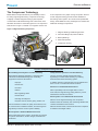
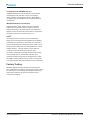
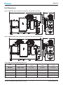
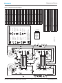
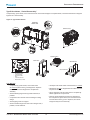
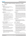
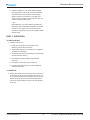
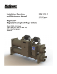
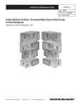
Magnitude®
Magnetic Bearing Centrifugal Chillers
Model WMC
C Vintage
145 to 400 Tons (500 to 1400 kW)
HFC-134a Refrigerant
Catalog 602-4
Table of Contents
Table of Contents
Introduction . . . . . . . . . . . . . . . . . . . . . . . . . . . . . . . . . 3
Refrigeration Diagram . . . . . . . . . . . . . . . . . . . . . . . . 12
Technology That Just Makes Sense . . . . . . . . . . . . . 3
Application Considerations . . . . . . . . . . . . . . . . . . . 13
Features and Benefits Summary . . . . . . . . . . . . . . . . 3
Location Requirements . . . . . . . . . . . . . . . . . . . . . . 13
Features and Benefits . . . . . . . . . . . . . . . . . . . . . . . . . 4
System Requirements . . . . . . . . . . . . . . . . . . . . . . . 13
The Compressor Technology . . . . . . . . . . . . . . . . . . . 4
Optimizing Efficiency . . . . . . . . . . . . . . . . . . . . . . . . 13
Integrated Variable Frequency Drive . . . . . . . . . . . . . 5
Evaporator . . . . . . . . . . . . . . . . . . . . . . . . . . . . . . . . 13
The Control Technology . . . . . . . . . . . . . . . . . . . . . . . 5
Condenser . . . . . . . . . . . . . . . . . . . . . . . . . . . . . . . . 14
Certifications and Standards . . . . . . . . . . . . . . . . . . . 6
Retrofit Knockdown . . . . . . . . . . . . . . . . . . . . . . . . . 15
Factory Testing . . . . . . . . . . . . . . . . . . . . . . . . . . . . . 7
Engineering Guide Specifications . . . . . . . . . . . . . . 17
Dimensions . . . . . . . . . . . . . . . . . . . . . . . . . . . . . . . . . 8
Unit Dimensions . . . . . . . . . . . . . . . . . . . . . . . . . . . . . 8
Drawing Notes . . . . . . . . . . . . . . . . . . . . . . . . . . . . . . 9
Options and Accessories . . . . . . . . . . . . . . . . . . . . . 10
Unit Options . . . . . . . . . . . . . . . . . . . . . . . . . . . . . . . 10
Vessel Options . . . . . . . . . . . . . . . . . . . . . . . . . . . . . 10
Controls Options . . . . . . . . . . . . . . . . . . . . . . . . . . . 10
Electrical Options . . . . . . . . . . . . . . . . . . . . . . . . . . . 10
Special Order Options . . . . . . . . . . . . . . . . . . . . . . . . 11
Manufactured in an ISO-certified facility
©2014 Daikin Applied. Illustrations and data cover the Daikin Applied product at the time of publication and we reserve the right to
make changes in design and construction at anytime without notice.
CAT 602-4 • MAGNITUDE® MODEL WMC CHILLERS
2
www.DaikinApplied.com
Introduction
Introduction
Magnitude® Magnetic Bearing Chillers
WME0700S
WME0500S
WMC400D
WMC290D
Model WME 500 - 700
WMC250D
WMC150D
WMC145D
WMC145S
100
200
Model WMC 145 - 400
300
400
500
600
700
Technology That Just Makes Sense
Features and Benefits Summary
The industry’s next generation of centrifugal chillers is here
today with Daikin Magnitude® chillers. The new technology
begins with centrifugal compressors utilizing magnetic
bearings for oil-free operation, integral variable-frequency
drives, and direct drive technology. The high efficiency
compressor is matched with highly efficient heat exchanges
to make an impressive chiller. Magnitude® chillers have many
important features:
The Compressor Technology
800
• Magnetic bearing system that results in greater efficiency
and reliability, more sustainable performance, reduced
operating and maintenance costs, and low vibration and
sound levels compared to traditional oil centrifugals.
Integrated Variable Frequency Drive
• State-of-the-art magnetic bearing compressor with oil-free technology
• Unit-mounted Variable Frequency Drive
• Positive pressure design
• Hermetic, permanent magnet, direct-drive motor
• User-friendly MicroTech® controls
• Open Choices™ feature for BAS of your choice
• Unit-mounted VFD modulates compressor speed to
obtain optimum efficiency at all load and lift conditions.
The Control Technology
• Onboard digital electronics provide smart controls and
includes a regenerative power system, user-friendly
operator interface, RapidRestore® option, and Open
Choices™ BAS flexibility.
Certifications and Standards
• R-134a refrigerant • Meets ASHRAE Std. 90.1, AHRI 550/590 and IBC/
(Zero ozone depletion and no refrigerant phase out)
OSHPD Seismic, and contributes to LEED ® credits.
• AHRI certification
Factory Testing
• Ensures trouble free startup and reliable operation.
www.DaikinApplied.com
3
CAT 602-4 • MAGNITUDE® MODEL WMC CHILLERS
Features and Benefits
Features and Benefits
The Compressor Technology
Model WMC’s exceptional efficiency and reliability is due to
its cutting-edge magnetic bearing compressor technology.
A digitally-controlled magnetic bearing system replaces
conventional oil lubricated bearings and a direct drive motor
eliminates the need for a lubricated gear box. The compressor
shaft, shown in Figure 1, levitates on a magnetic cushion and
is the compressor’s only major moving component. Sensors
at each magnetic bearing provide real-time feedback to
the bearing control system. As a result of this sophisticated
design, model WMC has many advantages over chillers with
traditional centrifugal compressors.
Figure 1: Magnetic Bearing Compressor
1. Magnetic Bearings and Bearing Sensors
3
1
3
2. Permanent Magnet Synchronous Motor
1
5
3. Backup Bearings
4. Shaft and Impellers
5. Compressor Cooling
2
4
Oil-Free Compressor Design Benefits
No Oil Management System = Greater Reliability
Totally Oil-Free Operation = Greater Efficiency
With magnetic bearings operating in a magnetic field
instead of oil-lubricated bearings, the oil handling
equipment is removed. No need for:
The use of oil-free magnetic bearing technology
significantly increases chiller efficiency by reducing
frictional losses within the bearing system.
oil pumps
oil reservoirs
In addition, efficiency improvements can be realized since
there is no oil to coat the heat transfer surfaces.
oil coolers
No Oil Loss = Sustainable Performance
oil filters
water regulating valves
oil relief valves
With no possibility of oil loss at light loads or due to
worn seals, the original energy saving efficiency can be
maintained for the life of the chiller.
oil storage and disposal
oil system controls, starter, piping, heaters, etc.
that are needed to maintain oil quality. These devices can
be a fault source in traditional chillers, and removing them
significantly increases unit and system reliability.
No Oil System = Low Vibration & Sound Levels
With the use of magnetic bearings, the compressor
vibration levels are extremely low, minimizing vibration that
could be transmitted to the structure.
With low vibration levels, sound levels are lower compared
to traditional centrifugal chillers.
No Oil System = Reduced Maintenance Costs
With oil removed from the system, oil samples, oil changes,
oil system maintenance, oil filter changes, and leaks are
eliminated.
CAT 602-4 • MAGNITUDE® MODEL WMC CHILLERS
4
www.DaikinApplied.com
Features and Benefits
The Control Technology
Additional Compressor Design Benefits
Model WMC’s magnetic bearing compressor design offers
many benefits not only because of its oil free design but also
because of its use of a positive pressure refrigerant and a
variable frequency drive.
It is only fitting that this revolutionary chiller design be
matched with the advanced control technology to give
you the ultimate chiller performance. Our control design
includes many unique energy-saving features and interface
enhancements.
Environmentally Friendly
Over time negative pressure chillers (such as those using
HCFC-123) may draw air and moisture into the system, which
can significantly increase energy consumption. Since the
Magnitude® WMC chiller uses a positive pressure refrigerant
(HFC-134a), the industry-leading efficiency can be maintained
for the life of the chiller. In addition, HFC-134a has no ozone
depletion potential and no phase-out schedule per the
Montreal protocol unlike HCFC type refrigerants used in low
pressure designs.
Low Operating Costs
Model WMC offers world class part load efficiency due to
its magnetic compressor design, which utilizes a variable
frequency drive. As a result, industry leading Integrated Part
Load Value (IPLV) ratings can be achieved. This allows for
significant energy savings at off-design conditions compared
to fixed-speed chillers. See AHRI Certification on page 6
for more information on IPLV ratings.
MicroTech® II Controller
The model WMC chiller utilizes MicroTech® II digital control
electronics to proactively manage unit operation and provide
control of external chilled water and cooling tower pumps.
The compressor runs at the minimum speed necessary to
maintain cooling capacity and lift (which decreases with lower
condenser water temperatures), thus minimizing energy usage
over the entire range of operating conditions. By constantly
monitoring chiller status and real time data, the MicroTech® II
controller will automatically take proactive measures to relieve
abnormal conditions or shut the unit down if a fault occurs.
Additional smart features that optimize operating efficiency
have been incorporated into our MicroTech® II controls:
• Cooling tower control including on/off, staging, and VFD
• Direct control of water pumps
• Chilled water rest
• Demand limit control
• Ability to stage up to four WMC chillers
Integrated Variable Frequency Drive
A Variable Frequency Drive (VFD) modulates compressor
speed in response to load and evaporator/condenser
pressure. When minimum speed is reached, moveable inlet
guide vanes redirect the gas flow into the impeller. VFD’s have
the following benefits:
• Reduced annual energy costs when there are long
periods of part load operation and/or low compressor lift
(lower condenser water temperature)
Operator Interface
Operation simplicity was one of the main considerations in the
development of the MicroTech® II control system. The operator
interface is a 15-inch, color touch-screen monitor that is
mounted on an adjustable arm. Key operating parameters and
setpoints are easily accessible. For added convenience, the
unit Operating and Maintenance Manual is also viewable on
the touch-screen panel.
In order to track chiller performance, the MicroTech® II
controller can record and plot water temperatures, refrigerant
pressures, and motor load. These values can be downloaded
through a convenient USB port in the interface and exported
into a spreadsheet for further evaluation and record purposes.
The trend history screen is shown in Figure 2.
• Reduced motor starting inrush current
• Reduced size of backup generators used to provide
emergency power to chillers used on mission critical
applications
• Increased power factor to reduce utility surcharges
WMC Reduced Harmonic Option
The Institute of Electrical and Electronics Engineers (IEEE)
has developed a standard (IEEE519) that defines acceptable
limits of site specific system current and voltage distortion.
The designer may wish to consult this standard to ensure
acceptable levels of harmonic distortion are maintained.
The standard VFD includes 3% line reactors, which
dramatically reduce the harmonic distortion. An optional unitmounted harmonic filter is available for all models to meet
lower harmonic level requirements.
www.DaikinApplied.com
5
CAT 602-4 • MAGNITUDE® MODEL WMC CHILLERS
Features and Benefits
Figure 2: Operator Interface Trend History Screen
Open Choices™ BAS Flexibility
The exclusive Open Choices™ feature provides seamless
integration and comprehensive monitoring, control, and
two-way data exchange using industry standard protocols
LonTalk®, BACnet ® or Modbus®. Open Choices™ offers simple
and inexpensive flexibility to use the Building Automation
System (BAS) of your choice without an expensive gateway
panel. Open Choices™ benefits include:
• Easy to integrate into your BAS of choice
• Factory- or field-installed communications module
• Integrated control logic for factory options
• Easy-to-use local user interface
• Comprehensive data exchange
Certifications and Standards
The controller memory (no batteries required) also retains
the fault history for troubleshooting and monitoring unit
performance. A time/date stamp is associated with each fault.
The fault history can be downloaded through the USB port.
RapidRestore®
Mission critical facilities such as data centers and hospitals
are demanding stringent capabilities for chillers to restart and
reach full load operation quickly in the event of a power loss.
With the capability of RapidRestore ®, Magnitude® model WMC
chillers are engineered to meet those needs. See Table 1
below for specifications.
As with many other Daikin Applied chiller products, the
Magnitude® model WMC meets all necessary certifications
and standards.
AHRI Certification
Part load performance can be presented in terms of Integrated
Part Load Value (IPLV), which is defined by AHRI Standard
550/590. Based on AHRI Standard 550/590, and as shown
in Figure 3, a typical chiller can operate up to 99% of the time
at off-peak conditions and usually spends most of this time at
less than 60% of design capacity.
Figure 3: IPLV Defined by AHRI Standard 550/590
RapidRestore ® – Quickly restores cooling capacity
when power is restored after a power failure
• Fast Loading – Amount of time required for the
chiller to reach a certain load condition
Table 1: WMC RapidRestore® Times- After Power
Restoration
*
Compressor Start
Fast Loading to 80% Load
43 sec
120 sec*
Estimated load time. Times may vary depending on operating conditions.
CAT 602-4 • MAGNITUDE® MODEL WMC CHILLERS
Percent Ton-Hour Weighting
• Compressor Start – Amount of time required for
the chiller to restart
50
40
42 Percent
45 Percent
30
20
10
12 Percent
1 Percent
0
100
75
50
25
Percent Load
WMC chillers are rated and certified to AHRI Standard
550/590. The ability of the WMC chillers to achieve very high
part load efficiencies, as evidenced by their world-class IPLV
ratings, is due primarily to the use of a variable frequency
drive and the low friction of the magnetic bearing system. For
more information on variable frequency drives, see Integrated
Variable Frequency Drive on page 5.
6
www.DaikinApplied.com
Features and Benefits
Compliance with ASHRAE Std. 90.1
ASHRAE Standard 90.1 was developed to assist owners
and designers make informed choices on a building’s
design, systems, and equipment selection. Model WMC
can significantly exceed ASHRAE 90.1 minimum efficiency
requirements.
IBC/OSHPD Seismic Certification
Daikin Magnitude® WMC chillers have been tested and
certified by an independent agency, experts in seismic
analysis and design to meet IBC seismic and OSHPD preapproval. Find more information about seismic requirements
and HVAC systems at www.DaikinApplied.com.
LEED®
For building owners who wish to pursue Leadership in
Energy and Environmental Design (LEED ®) Green Building
Certification, the performance of the WMC may contribute
points towards Energy and Atmosphere (EA) Credits 1 and 4.
Points earned for EA Credit 1 are awarded based on overall
building efficiency. The high efficiency of the WMC will
contribute to the total points earned for this credit.
EA Credit 4 qualification is partially determined by tonnage
and refrigerant quantity. Vessel stack and tube count
selections will affect the quantity of refrigerant in the chiller.
Most WMC models qualify for the EA Credit 4. Consult with
your Daikin Applied sales representative for more information.
Factory Testing
All Daikin Applied centrifugal chillers (50 or 60 hertz) are
factory-tested prior to shipment. Operating and safety controls
are checked for correct settings and operation. This testing
helps reduce field start-up issues and maintain critical
construction schedules.
www.DaikinApplied.com
7
CAT 602-4 • MAGNITUDE® MODEL WMC CHILLERS
Dimensions
Dimensions
Unit Dimensions
Figure 4: WMC145S (2-pass, right-hand configuration, with grooved connections)
L
W
H
Figure 5: WMC145-400D (2-pass, right-hand configuration, with grooved connections)
W
L
H
Table 2: WMC145S and WMC145-400D Dimensions Model
Heat Exchanger
Length
in (mm)
Width
in (mm)
Height
in (mm)
WMC145S
E2209 / C2009
134.3 (3411)
43.5 (1105)
81.0 (2057)
WMC145D
E2212 / C2012
134.3 (3411)
43.5 (1105)
80.8 (2052)
WMC150D
E2212 / C2012
169.2 (4298)
43.5 (1105)
80.8 (2052)
WMC250D
E2609 / C2209
134.2 (3409)
47.2 (1199)
83.8 (2129)
WMC290D
E2612 / C2212
169.1 (4295)
47.2 (1199)
83.9 (2131)
WMC400D
E3012 / C2612
168.5 (4280)
55.2 (1402)
94.3 (2395)
CAT 602-4 • MAGNITUDE® MODEL WMC CHILLERS
8
www.DaikinApplied.com
Dimensions
Drawing Notes
1. Final connections must allow for 0.5 inch +/- (12.7mm)
manufacturing tolerances.
7. All water connections are given in standard U.S. pipe
sizes. Standard connections are suitable for welding or
grooved couplings.
2. 1.00-inch FPT (25.4 mm) evaporator and condenser
relief valves must be piped per ANSI / ASHRAE 15.
Number of relief valves is 1 per evaporator and 2 per
condenser.
8. Unit shown has standard right-hand water connections.
Left-hand connections are available for either vessel.
For right hand evaporator the inlet and outlet nozzles are
reversed. ANSI-flanged connections are available upon
request. When using ANSI-flanged connections add 0.5
inch (13 mm) to each flanged end.
3. 0.375 inch (9 mm) suction nozzle relief valve must be
piped per ANSI / ASHRAE 15.
4. Minimum Clearances (See Figure 6):
9. Dimensions shown are for units (evaporator / condenser)
with standard design pressures. The waterside design
pressure is 150 psi (1034 kPa). Consult the factory for
unit dimensions with higher design pressures.
• Installation layout should be designed by qualified
personnel familiar with local codes.
• Allow a minimum of 3 ft. on all for sides and the top
sides of chiller to allow for service access.
• Provide a minimum of 3 ft. clearance in front of chiller
starter panel or according to NEC or local codes.
10. The unit vibration isolator pads are provided for field
installation and when fully loaded are 0.25 inches
(6 mm) thick.
• Provide a minimum of 12 ft. clearance on one end of
chiller models WMC145S, 145D, and 250D for tube
removal.
11. These values are for units with standard wall thickness
copper tubing only.
12. The shipping skid adds 4.00 inches (105 mm) to the
overall unit height.
• Provide a minimum of 15 ft clearance on one end of
chiller models WMC150D, 290D, and 400D for tube
removal.
13. If main power wiring is brought up through the floor, this
wiring must be outside the envelope of the unit.
5. Electric Panels- Most codes require 48 inches
(1219 mm) clearance in front of control boxes and
electrical panels. Check codes for your location.
14. The unit is shipped with an operating charge of
refrigerant.
6. 3.25-inch (83 mm) diameter lifting holes are provided.
See installation manual (available at www.DaikinApplied.
com) for lifting instructions.
15. Optional marine water box connections are available
upon request.
Figure 6: Minimum Clearances Based on Standard Waterboxes
Minimum 3’ Clearance on all sides and top of chiller; Minimum 12’ or 15’ Clearance (depending on model) on one side for tube removal.
TOP VIEW
Minimum 3’ Clearance
Minimum 12’ Clearance for Tube Removal (Models WMC145S, 145D, 250D)
Minimum 15’ Clearance for Tube Removal (Models WMC150D, 290D, 400D)
Minimum 3’ Clearance
Minimum 3’ Clearance
NOTE: Hinged type waterboxes may require more clearance. Consult your Daikin Applied sales representative for details.
www.DaikinApplied.com
9
CAT 602-4 • MAGNITUDE® MODEL WMC CHILLERS
Options and Accessories
Options and Accessories
Unit Options
Export Packaging
A wooden skid that aids in moving the unit and tight fitting
plastic covering the entire unit to protect it from dirt and grime
during transit and storage are standard. Open and closed
crating is also offered as an option.
Pumpout Unit, With or Without Storage Vessel
Available in a variety of sizes, single-phase or three-phase,
with and without tanks. Contact your Daikin Applied sales
office for details.
Extended Warranties
Extended 1, 2, 3, or 4 year warranties for parts only or for
parts and labor are available for the compressor/motor only,
the entire unit, or the entire unit including refrigerant.
Witness Performance Test
The specified full and/or part load tests, as ordered, are
performed in the presence of the customer under the
supervision of a factory engineer and include compilation of
the test data onto an easy-to-read spreadsheet.
Non-Witness Test
The specified full and/or part load run tests, as ordered, are
performed under the supervision of a factory engineer; data is
compiled, certified and transmitted to the customer.
Refrigerant Charge
Holding charge of Nitrogen or R-134a. Shipping with a full
charge of R-134a is standard.
Knockdown Shipment
Several options for a knockdown shipment to facilitate unit
placement. See Retrofit Knockdown on page 15 for details.
Vessel Options
Marine Waterboxes
Single Insulation - Evaporator Shell / Suction Piping
0.75-inch thermal insulation on cold surfaces excluding heads
and waterboxes.
Single Insulation - Evaporator Heads and
Waterboxes
0.75-inch thermal insulation.
Double Insulation - Evaporator Shell / Suction
Piping
1.5-inch thermal insulation on cold surfaces (0.75-inch on
suction piping) excluding heads and waterboxes.
Double Insulation - Evaporator Heads and
Waterboxes
1.5-inch thermal insulation.
Hinged Waterbox Covers and Heads
Hinges for marine waterbox covers or heads (compact
waterboxes) to aid in heat exchanger maintenance.
Tube Size, Wall Thickness and Material
A wide range of tube options are available to accommodate
most flow rates and fluids. Standard wall thickness is 0.025inch, optional 0.028-inch or 0.035-inch.
Controls Options
BAS Interface Module
Factory-installed on the unit controller for the applicable
protocol being used (Can also be retrofit):
• BACnet ® MS/TP
• BACnet ® IP
• BACnet ® Ethernet
• LonWorks®
• Modbus® RTU
Electrical Options
Provide tube access for inspection, cleaning, and removal
without dismantling water piping.
Power Panel High Short Circuit Current Rating
Flanges (grooved connections are standard)
EMI Filter
ANSI raised face flanges on either the evaporator or
condenser. Mating flanges are by others.
Factory-installed option. Radio interference filter.
300 psi Water Side Vessel Construction
65 kA panel rating (Standard is 35 kA).
Ground Fault Protection
For high pressure water systems, typically high-rise building
construction (150 psi is standard).
Protects equipment from arcing ground fault damage from
line-to-ground fault currents less than those required for
conductor protection.
Epoxy and Ceramic Coating
Input Power Meter
Evaporator and condenser heads and marine waterboxes can
be coated for corrosion protection with either epoxy or ceramic
coatings. Tube sheets may also be ceramic coated.
Allows display of input phase amps and volts on the operator
interface screen.
CAT 602-4 • MAGNITUDE® MODEL WMC CHILLERS
10www.DaikinApplied.com
Options and Accessories
RapidRestore®
Allow chillers to restart and reach full load operation quickly in
the event of a power loss event. See RapidRestore® on page
6 for more details.
Special Order Options
The following special order options are available; requiring
factory pricing, additional engineering, and possible dimension
changes or extended delivery:
1. Non-standard location of nozzle connections on heads
(compact waterboxes) or marine waterboxes.
2. Special corrosion inhibiting coatings on any “wetted
surface” including tubesheets, heads (compact
waterboxes), marine waterboxes, or nozzles.
3. Clad tube sheets.
4. Sacrificial anodes in heads (compact waterboxes) or
marine waterboxes.
5. Spacer rings on heads to accommodate automatic tube
brush cleaning systems (installed by others).
www.DaikinApplied.com11
CAT 602-4 • MAGNITUDE® MODEL WMC CHILLERS
CAT 602-4 • MAGNITUDE® MODEL WMC CHILLERS
28
33
16
32
12
DISCHARGE
HV
20
19
17
18
10
1
2
COMPRESSOR COOLING
HV
HV
38
PT
3
SUCTION
HV
37
6
36
HV
9
SUCTION
S
21
FG
30
22
STAGING
4
23
HV
HV
S
31
CONDENSER
13
EVAPORATOR
5
HV
US05
TI
TE
11
29
CFS
EF
CF
24
25
HV
EFS
8
7
FE
FI
FE
14
FI
IN
OUT
IN
OUT
US04
COMPRESSOR COOLING
DISCHARGE
MAIN LIQUID
US03
TI
TE
TE
TI
39
STAGING
US02
TI
TE
TE
TI
TT
US10
PT
PT
PT
BMCC
TT
TT
COMP
TT
BMCC
COMP
HV
HV
34
27
35
26
15
PT
TI
TE
BUTTERFLY
VALVE
INSULATED
THREE-WAY
VALVE
TEMPERATURE
SENSOR
SPRING LOADED
RELIEF VALVE
UNIT
CONTROL
BOX
BUTTERFLY VALVE
BUTTERFLY VALVE
PRESSURE TAP
RELIEF VALVE
SERVICE VALVE
STAGING VALVE
STAGING VALVE
BALL VALVE
EXPANSION VALVE
BALL VALVE
BALL VALVE
FILTER DRYER
RELIEF VALVE
SIGHT GLASS
PRESSURE TAP
RELIEF VALVE
3-WAY VALVE
RELIEF VALVE
SERVICE VALVE
PRESSURE TAP
RELIEF VALVE
FILTER DRYER
BALL VALVE
BALL VALVE
SERVICE VALVE
CHECK VALVE
CHECK VALVE
PRESSURE TAP
PRESSURE TAP
PRESSURE TAP
PRESSURE TAP
RELIEF VALVE
RELIEF VALVE
PRESSURE TAP
PRESSURE TAP
MANUAL
MANUAL
N/A
MANUAL
MANUAL
AUTOMATIC
AUTOMATIC
MANUAL
AUTOMATIC
MANUAL
MANUAL
N/A
MANUAL
N/A
N/A
AUTOMATIC
AUTOMATIC
AUTOMATIC
MANUAL
N/A
MANUAL
N/A
MANUAL
MANUAL
MANUAL
AUTOMATIC
AUTOMATIC
N/A
N/A
N/A
N/A
AUTOMATIC
AUTOMATIC
N/A
N/A
N/A
MANUAL
AUTOMATIC
MANUAL
VALVE
CONTROL
DESCRIPTION
CONDENSER FLOW SWITCH
EVAPORATOR FLOW SWITCH
CONDENSER FLOW SIGNAL TO CHILLER CONTROL
EVAPORATOR FLOW SIGNAL TO CHILLER CONTROL
CF
EF
CFS
EFS
FLOW SWITCH
EVAPORATOR ENTERING WATER TEMPERATURE
CONDENSER ENTERING WATER TEMPERATURE
CONDENSER LEAVING WATER TEMPERATURE
LIQUID LINE TEMPERATURE
EVAPORATOR LEAVING WATER TEMPERATURE
DESCRIPTION
UNIT CONTROLLER
5
6
7
8
9
10
11
12
13
14
15
16
17
18
19
20
21
22
23
24
25
26
27
28
29
30
31
32
33
34
35
36
37
38
39
PRESSURE TAP
RELIEF VALVE
RELIEF VALVE
SERVICE VALVE
LABEL
BUBBLE NO.
US02
US03
US04
US05
CS10
BUBBLE NO.
CF
EF
US10
US05
US04
US03
US02
BEARING MOTOR COMPRESSOR CONTROLER
(INTERNAL TO COMPRSSOR)
TEMPERATURE/PRESSURE TRANSDUCER
(INTERNAL TO COMPRESSER)
FLOW SWITCH
FILTER DRYER
ELECTRONIC
EXPANSION
VALVE
RELIEF VALVE
VENT / DRAIN
CHECK VALVE
(SPRING)
SIGHT GLASS
CENTRIFUGAL
COMPRESSOR
FLOW DIAGRAM, WMC
332632901
0A
BMCC
TT
FI
FE
S
SERVICE VALVE
BALL VALVE
FG
FLOW CHART LEGEND
1
2
3
4
BUBBLE
NO.
Refrigeration Diagram
Refrigeration Diagram
Figure 7: Refrigeration System Diagram
12www.DaikinApplied.com
Application Considerations
Application Considerations
Location Requirements
Daikin WMC units are designed only for indoor, weatherprotected, non-freezing areas consistent with the NEMA 1
rating on the chiller, controls, and electrical panels. Equipment
room temperature for operating and standby conditions is
40°F to 104°F (4.4°C to 40°C).
System Requirements
Piping
Piping must be adequately supported to remove weight and
strain on the chiller’s fittings and connections. Be sure piping
is adequately insulated for job conditions. Install a cleanable
20-mesh water strainer upstream of the evaporator and
condenser. Install enough shutoff valves to permit draining
water from the evaporator or condenser without draining the
complete system.
NOTE: This product, in its standard configuration, is
equipped with a shell and tube evaporator with
carbon steel shell and copper tubes. The water or
other fluid used in contact with the wetted surfaces of
the heat exchangers must be clean and non-corrosive
to the standard materials of construction. Daikin
Applied makes no warranty as to the compatibility
of fluids and materials. Non-compatible fluids may
void the equipment warranty. If the compatibility of
the fluid with the standard materials of construction
is in question, a professional corrosion consultant
should administer the proper testing and evaluate
compatibility.
Variable Fluid Flow Rates and Tube Velocities
Many chiller system control and energy optimization
strategies require significant changes in evaporator water
flow rates. The Magnitude® chiller line is well suited to take
full advantage of these energy saving opportunities using
different combinations of shell sizes, number of tubes, and
pass arrangements.
Both excessively high and excessively low fluid flow rates
should be avoided. Excessively high fluid flow rates and
correspondingly high tube velocities will result in high fluid
pressure drops, high pumping power, and potentially tube
erosion or corrosion damage. Excessively low fluid flow rates
and correspondingly low velocities should also be avoided as
they will result in poor heat transfer, high compressor power,
sedimentation and tube fouling.
System Water Volume
All chilled water systems need adequate time to recognize a
load change to avoid short cycling of the compressors or loss
of control. The potential for short cycling usually exists when
the building load falls below the minimum chiller plant capacity
or on close-coupled systems with very small water volumes.
Some of the things the designer should consider when looking
at water volume are the minimum cooling load, the minimum
www.DaikinApplied.com13
chiller plant capacity during the low load period and the
desired cycle time for the compressors.
Assuming that there are no sudden load changes and that
the chiller plant has reasonable turndown, a rule of thumb of
“gallons of water volume equal to two to three times the chilled
water gpm flow rate” is often used.
A properly designed storage tank should be added if the
system components do not provide sufficient water volume.
Vibration Mounting
The Magnitude® WMC chiller is almost vibration-free.
Consequently, floor mounted spring isolators are not usually
required. Rubber mounting pads are shipped with each unit. It
is recommended to continue to use flexible piping connectors
to reduce sound transmitted into the pipe and to allow for
expansion and contraction.
System Energy Analysis
The Daikin Energy Analyzer™ II program is an excellent tool to
investigate the entire system efficiency, quickly and accurately.
It is especially good at comparing different system types and
operating parameters. Contact your local Daikin Applied sales
office for assistance on your particular application.
Optimizing Efficiency
A key to improving energy efficiency for any chiller is
minimizing the compressor pressure lift. Reducing the lift
reduces the compressor work and its energy consumption
per unit of output. The chiller typically consumes more energy
than any other component in the chiller system. Therefore,
the optimum plant design must take into account all of the
interactions between chiller, pumps, and tower.
Evaporator
Reduced Evaporator Fluid Flow
Several popular chiller plant control practices — including
Variable Primary Flow systems — advocate reducing the
evaporator fluid flow rate as the chiller capacity is reduced.
This practice can significantly reduce the evaporator pumping
power while having little effect on chiller energy consumption.
The Magnitude® WMC chillers, with their wide range of shell,
tube, and pass combinations, are ideal for application in
variable evaporator flow systems as long as the minimum and
maximum tube velocities are taken into consideration when
selecting the chiller.
If it is decided to vary the evaporator water flow rate, the rate
of change should not exceed 50% per minute and should not
exceed the minimum or maximum velocity limits.
Evaporator Entering Water Temperature
The maximum temperature of water entering the chiller
on standby must not exceed 115°F (46.1°C). Maximum
CAT 602-4 • MAGNITUDE® MODEL WMC CHILLERS
Application Considerations
temperature entering on start-up must not exceed 90°F
(32°C).
savings in chiller power would suggest, due to the excessive
fan power required.
Evaporator Leaving Water Temperature
In this scenario, cooling tower fans would continue to operate
at 100% capacity at low wet bulb temperatures. The tradeoff between better chiller efficiency and fan power should
be analyzed for best overall system efficiency. The Energy
Analyzer™ II program (available from your Daikin Applied
sales representative) can optimize the chiller/tower operation
for specific buildings in specific locales.
Warmer leaving chilled water temperatures will raise the
compressor’s suction pressure and decrease the lift,
improving efficiency. Using 45°F (7°C) leaving water instead of
the typical 42°F (5.5°C) will significantly reduce chiller energy
consumption.
Evaporator Water Temperature Difference
The industry standard has been a 10°F (5.5°C) temperature
drop in the evaporator. Increasing the drop to 12°F or 14°F
(6.6°C or 7.7°C) can improve chiller efficiency and reduce
pump energy consumption.
Condenser
Reduced Condenser Fluid Flow
Several popular chiller plant control practices also advocate
reducing the condenser fluid flow rate as the chiller load is
reduced. This practice can significantly reduce the condenser
pumping power, but it may also have the unintended
consequence of significantly increasing compressor power
since the leaving condenser water temperature is directly
related to compressor lift and power. The higher compressor
power will typically be larger than the condenser pumping
power reduction and will result in a net increase in chiller plant
energy consumption. Therefore, before this strategy is applied
for energy saving purposes it should be extensively modeled
or used in an adaptive chiller plant control system which will
take into account all of the interdependent variables affecting
chiller plant energy. If it is decided to use variable condenser
fluid flow, the model WMC chiller can operate effectively as
long as the minimum and maximum tube velocities are taken
into consideration when selecting the chiller.
Condenser Entering Water Temperature
As a general rule, a 1°F (0.5°C) drop in condenser entering
water temperature will reduce chiller energy consumption by
two percent. Cooler water lowers the condensing pressure
and reduces compressor work. One or two degrees can make
a noticeable difference. The incremental cost of a larger tower
can be small and provide a good return on investment.
When the ambient wet bulb temperature is lower than design,
the entering condenser water temperature of Magnitude®
WMC chillers can be lowered to improve chiller performance.
Chillers can start with entering condenser water temperatures
as low as 40°F (4.4°C). For short periods of time during
startup, the entering condenser water temperature can even
be lower than the leaving chilled water temperature.
Depending on local climatic conditions, using the lowest
possible entering condenser water temperature may be more
costly in total system power consumed than the expected
CAT 602-4 • MAGNITUDE® MODEL WMC CHILLERS
Even with tower fan control, some form of water flow control,
such as tower bypass, is recommended.
Figure 8 and Figure 9 illustrate two temperature-actuated
tower bypass arrangements. The “Cold Weather” scheme,
Figure 9, provides better startup under cold ambient air
temperature conditions. The bypass valve and piping are
indoors and thus warmer, allowing for warmer water to be
immediately available to the condenser. The check valve may
be required to prevent air at the pump inlet.
Figure 8: Tower Bypass- Mild Weather Operation
≈
≈
Figure 9: Tower Bypass- Cold Weather Operation
(Bypass Indoors)
≈
≈
Condenser Water Temperature Difference
The industry standard of 3 gpm/ton or about a 9.5°F (5.3°C)
delta-T works well for most applications.
Condenser Water Temperature Control
The standard MicroTech® II controller is capable of four stages
of tower fan control plus an analog control of either a threeway tower-bypass valve or variable speed tower-fan motor.
Stages are controlled from condenser-water temperature.
The three-way valve can be controlled to a different water
temperature or track the current tower stage. This allows
optimum chilled water plant performance based upon specific
job requirements.
14www.DaikinApplied.com
Application Considerations
Condenser Pumps and Piping
The condenser water pump(s) must be cycled off when the last
chiller of the system cycles off. This will keep cold condenser
water from migrating refrigerant to the condenser. Cold liquid
refrigerant in the condenser can make start up difficult. In
addition, turning off the condenser water pump(s) when the
chillers are not operating will conserve energy.
Include thermometers and pressure gauges at the chiller inlet
and outlet connections and install air vents at the high points
of piping. Where noise and vibration are critical and the unit
is mounted on spring isolators, flexible piping and conduit
connections are necessary.
Retrofit Knockdown
It is estimated that fifty percent of retrofit applications require partial or complete disassembly of the chiller. Magnitude® WMC
chillers are relatively easy to disassemble due to the small compressor size, simplified refrigerant piping and the absence of a
lubrication system with its attendant components and piping. Two knockdown arrangements, Type A shown in Figure 10 and Type
B shown in Figure 11, are available as options.
Type A Knockdown, “Bolt-Together Construction”
Chillers are built and shipped completely assembled with bolt-together construction on major components for field disassembly
and re-assembly on the job site.
Figure 10: Type A Knockdown
ISOMETRIC
FRONT VIEW
REAR VIEW
DETAIL B
POWER BOX
OITS PANEL BOXED
AND SECURLY
FASTENED TO
UNIT CONTROL BOX
CONTROL BOX
DETAIL A
Type A Scope:
• Chiller components are manufactured with bolt-together
construction designed for field disassembly and reassembly on-site.
• Unit ships completely assembled to the jobsite.
• Suction and discharge lines have bolt-on flanges.
• Site disassembly and re-assembly must be supervised
or completed by Daikin Applied service personnel.
• Unit ships with vessel and/or head insulation, if ordered.
• Unit ships with full factory refrigerant charge in the
chiller.
www.DaikinApplied.com15
• Bolt-together construction allows for site disassembly
based on required clearances at each jobsite.
• Ideal for retrofit applications.
CAT 602-4 • MAGNITUDE® MODEL WMC CHILLERS
Application Considerations
Type B Knockdown, “Partial Disassembly”
Compressor(s), power boxes, and control boxes are removed and shipped on separate skids; combined vessel stack is shipped
together as a sub-assembly.
Figure 11: Type B Knockdown
ISOMETRIC
FRONT VIEW
COMPRESSOR(S)
DETAIL C
DETAIL A
BLOCKOFF
BLOCKOFF
DETAIL B
DETAIL D
COMPRESSOR(S)
GLUE
POWER BOX
CONTROL BOX
OITS PANEL BOX
CRATE TO CONTAIN:
•
•
•
•
•
•
DISCHARGE PIPING
SUCTION ELBOW
MOTOR COOLING
GLUE
LOOSE INSULATION
MISCELLANEOUS ITEMS
Type B Scope:
• Compressor(s), power boxes, and control boxes
are removed (at the factory) and shipped on separate
skids; vessel stack is shipped as a complete subassembly.
• All associated piping and wiring remain attached, if
possible.
• Compressors and vessels receive a Nitrogen holding
charge.
• All free piping ends are capped.
• Unit ships with vessel and/or head insulation, if ordered.
• Refrigerant will not be shipped with the chiller and must
be procured locally.
• Site re-assembly must be supervised or completed by
Daikin Applied service personnel.
• Ideal for retrofit applications where it is desired that
the compressors, power boxes, and control boxes be
removed at the factory, prior to shipment, and where
refrigerant may be secured locally.
• Suction and discharge lines have bolt-on flanges and, if
possible, remain attached.
CAT 602-4 • MAGNITUDE® MODEL WMC CHILLERS
16www.DaikinApplied.com
Engineering Guide Specifications
Engineering Guide Specifications
MAGNITUDE® MAGNETIC BEARING CENTRIFUGAL CHILLERS
PART 1 - GENERAL
1.1 SUMMARY
A. Section includes design, performance criteria,
refrigerants, controls, and installation requirements for
water-cooled centrifugal chillers.
1.2 REFERENCES
A. Comply with the following codes and standards: AHRI
550/590, AHRI 575, NEC, ANSI/ASHRAE 15, OSHA as
adopted by the State, ETL, ASME Section VIII
1.3 SUBMITTALS
A. Submittals shall include the following:
1. Dimensioned plan and elevation view, including
required clearances, and location of all field piping
and electrical connections.
2. Summaries of all auxiliary utility requirements such
as: electricity, water, air, etc. Summary shall indicate
quality and quantity of each required utility.
3. Diagram of control system indicating points for field
interface and field connection. Diagram shall fully
depict field and factory wiring.
4. Manufacturer’s certified performance data at full load
plus IPLV or NPLV.
5. Installation and Operating Manuals.
1.4 QUALITY ASSURANCE
A. Regulatory Requirements: Comply with the codes and
standards in Section 1.2.
B. Chiller manufacturer plant shall be ISO Certified.
C. The chiller shall be factory tested at the manufacturer’s
plant prior to shipment on an AHRI approved test stand.
1.5 DELIVERY AND HANDLING
A. Chillers shall be delivered to the job site completely
assembled and charged with refrigerant R134a and be
shipped on skids with a weather resistant cover.
– OR –
A. [For Type A Knockdowns] The unit shall be delivered
to the job site completely assembled and charged with
refrigerant and ready for field knockdown. Contractor
shall leak test, recover refrigerant, evacuate, and charge
with refrigerant after reassembly.
– OR –
www.DaikinApplied.com17
A. [For Type B Knockdowns] The compressor, suction and
discharge piping, VFD power panel and touch screen
shall be removed and shipped separately. All wiring
and piping shall remain attached where possible. The
remaining loose parts shall be packaged in a separate
crate. The unit is to be factory tested and shipped with
a nitrogen holding charge, evaporator insulated and a
kit for compressor insulation. Contractor shall leak test,
evacuate and charge with refrigerant after reassembly.
B. Comply with the manufacturer’s instructions for rigging
and transporting units. Leave protective covers in place
until installation.
1.6 WARRANTY
A. The chiller manufacturer’s warranty shall cover parts
and labor costs for the repair or replacement of defects
in material or workmanship, and include refrigerant for
the entire unit, for a period of one year from equipment
startup or 18 months from shipment, whichever occurs
first [OPTION] and also include an additional extended
warranty for one -OR- two- OR- three -OR- four years
on the entire unit -OR- on entire unit including refrigerant
coverage -OR- compressor only.
1.7 MAINTENANCE
A. Maintenance of the chillers in accordance with
manufacturer’s recommendations as published in the
installation and maintenance manuals shall be the
responsibility of the owner.
PART 2 - PRODUCTS
2.1 ACCEPTABLE MANUFACTURERS
A. Basis of Design - Daikin Magnitude® model WMC,
including the standard product features and all special
features required per the plans and specifications.
B. Equal Products - Equipment manufactured by [ENTER
MANUFACTURER NAME HERE] may be acceptable
as an equal. Naming these products as equal does not
imply that their standard construction or configuration
is acceptable or meets the specifications. Equipment
proposed “as equal”, must meet the specifications
including all architectural, mechanical, electrical, and
structural details, all scheduled performance and the job
design, plans and specifications.
2.2 UNIT DESCRIPTION
A. Provide and install as shown on the plans a factory
assembled, charged, and tested water-cooled packaged
CAT 602-4 • MAGNITUDE® MODEL WMC CHILLERS
Engineering Guide Specifications
centrifugal chiller. Chillers shall have no more than two
oil-free, magnetic bearing, semi-hermetic centrifugal
compressors (no exceptions). Each compressor shall
have an integrated variable-frequency drive operating
in concert with inlet guide vanes for optimized full and
part load efficiency. On two-compressor units, the
evaporator and condenser refrigerant sides and the
expansion valve shall be common and the chiller shall
be capable of running on one compressor with the
other compressor or any of its auxiliaries inoperable or
removed.
to facilitate leak testing.
C. Performance: Refer to chiller performance rating.
D. Acoustics: Sound pressure for the unit shall not exceed
the following specified levels. Provide the necessary
acoustic treatment to chiller as required. Sound data
shall be measured in dB according to AHRI Standard
575 and shall include overall dBA. Data shall be the
highest levels recorded at all load points.
Octave Band
63
125
250
500
1000
2000
4000
8000
Overall
dBA
2.3 DESIGN REQUIREMENTS
A. General: Provide a complete water-cooled, semihermetic oil-free centrifugal compressor water chiller as
specified herein. The unit shall be provided according
to standards indicated in Section 1.2. In general, unit
shall consist of one or two magnetic bearing, completely
oil-free centrifugal compressors, refrigerant, condenser
and evaporator, and control systems including integrated
variable frequency drive, operating controls and
equipment protection controls. Chillers shall be charged
with refrigerant HFC-134a. If manufacturer offers a
chiller using any HCFC refrigerant, manufacturer shall
provide, in writing, documentation signed by an officer of
the company assuring refrigerant availability and price
schedule for a 20-year period.
B. The entire chiller system, including all pressure vessels,
shall remain above atmospheric pressure during all
operating conditions and during shut down to ensure
that non-condensables and moisture do not contaminate
the refrigerant and chiller system. If any portion of the
chiller system is below atmospheric pressure during
either operation or shut down, the manufacturer shall
include, at no charge:
1. A complete purge system capable of removing noncondensables and moisture during operation and
shut-down.
2. A 20-year purge maintenance agreement
that provides parts, labor, and all preventative
maintenance required by the manufacturer’s
operating and maintenance instructions.
3. The manufacturer shall also include at no charge
for a period of 20 years an annual oil and refrigerant
analysis report to identify chiller contamination due
to vacuum leaks. If the analysis identifies water, acid,
or other contaminant levels higher than specified by
the manufacturer, the oil and/or refrigerant must be
replaced or returned to the manufacturer’s original
specification at no cost to the owner.
4. The manufacturer shall include a factory-installed and
wired system that will enable service personnel to
readily elevate the vessel pressure during shutdown
CAT 602-4 • MAGNITUDE® MODEL WMC CHILLERS
2.4 CHILLER COMPONENTS
A. Compressors:
1. The unit shall utilize magnetic bearing, oil-free, semihermetic centrifugal compressors. The compressor
drive train shall be capable of coming to a controlled,
safe stop in the event of a power failure.
2. The motor shall be of the semi-hermetic type,
of sufficient size to efficiently fulfill compressor
horsepower requirements. It shall be liquid refrigerant
cooled with internal thermal sensing devices in the
stator windings. The motor shall be designed for
variable frequency drive operation.
a. If the compressor design requires a shaft seal
to contain the refrigerant, the manufacturer shall
supply a 20 year parts and labor warranty on the
shaft seal and a lifetime refrigerant replacement
warranty if a seal failure leads to refrigerant
loss, or the chiller manufacturer shall assume
all costs to supply and install a self contained
air conditioning system in the mechanical space
sized to handle the maximum heat output of the
open drive motor. The energy required to operate
this air conditioning system shall be added to
the chiller power at all rating points for energy
evaluation purposes.
b. If the compressor/motor uses any form of
antifriction bearing (roller, ball, etc), the chiller
manufacturer shall provide the following at no
additional charge:
• A 20-year bearing warranty and all
preventative maintenance as specified by
the manufacturer’s published maintenance
instructions.
• At start up, a three-axis vibration analysis and
written report to establish bearing condition
baseline.
• An annual three-axis vibration analysis and
written report indicating bearing condition.
18www.DaikinApplied.com
Engineering Guide Specifications
3. The chiller shall be equipped with a refrigerant cooled
and integrated Variable Frequency Drive (VFD) to
automatically regulate compressor speed in response
to cooling load and the compressor pressure lift
requirement. If a condenser water-cooled VFD is
supplied, the manufacturer shall supply factory
installed dual water filters with a bypass valve and
pressure differential switch factory wired to the chiller
control panel to indicate that a filter has clogged and
requires service. The pressure differential switch
shall also provide a separate dry contact which can
be connected to the BAS system as a means of
notifying operating personnel of the need to service
the filters. If the condenser cooling circuit includes an
intermediate heat exchanger, it must be of the brush
cleanable shell and tube style. Brazed plate heat
exchangers which cannot be field cleaned are not
acceptable. Movable inlet guide vanes and variable
compressor speed, shall provide unloading. The
chiller controls shall coordinate compressor speed
and guide vane position to optimize chiller efficiency.
4. Each compressor circuit shall be equipped with a line
reactor to help protect against incoming power surges
and help reduce harmonic distortion.
5. [OPTIONAL] The chiller shall be equipped with a
factory-mounted and wired passive harmonic filter
guaranteed to meet the IEEE Standard 519 at an Isc/
IL ratio greater than 20.
B. Evaporator and Condenser:
1. The evaporator and condenser shall be separate
vessels of the shell-and-tube type, designed,
constructed, tested and stamped according to the
requirements of the ASME Code, Section VIII. The
tubes shall be individually replaceable and secured to
the intermediate supports without rolling.
–OR– [titanium] tubes rolled into [carbon steel] –
OR– [Monel-clad] –OR– [stainless steel clad] –OR–
[titanium-clad] –OR– [ceramic-coated] tube sheets.
Water connections shall be [grooved suitable for
grooved couplings]—OR– [flanged]. The water side
shall be designed for a minimum of [150 psig] –OR–
[300 psig]. The condenser shall have [dished heads
with valved drain and vent connections] –OR– [shall
be equipped with marine waterboxes with removable
covers and vent and drain connections]. The
condenser shall have [right-hand]
–OR– [left-hand] connections when looking at the
unit control panel.
4. An electronic expansion valve shall control refrigerant
flow to the evaporator. Fixed orifice devices or float
controls with hot gas bypass are not acceptable
because of inefficient control at low load conditions.
The liquid line shall have moisture indicating sight
glass.
5. Re-seating type spring loaded pressure relief valves
according to ASHRAE-15 safety code shall be
furnished. The evaporator shall be provided with
single or multiple valves. The condenser shall be
provided with dual relief valves equipped with a
transfer valve so one relief valve can be removed for
testing or replacement without loss of refrigerant or
removal of refrigerant from the condenser. Rupture
disks are not acceptable.
6. The evaporator, suction line, and any other
component or part of a component subject to
condensing moisture shall be insulated with UL
recognized 3/4 inch OR 1 ½ inch closed cell
insulation. All joints and seams shall be carefully
sealed to form a vapor barrier.
7. [OPTIONAL] The evaporator waterbox shall be
insulated with UL recognized 3/4 inch OR 1 ½ inch
closed cell insulation. All joints and seams shall be
carefully sealed to form a vapor barrier.
2. The evaporator shall be flooded type with [0.025
in.] –OR– [0.028 in.] –OR– [0.035 in.] wall [copper]
–OR– [90/10 CuNi] tubes rolled into [carbon steel]
–OR– [ceramic-coated steel] tubesheets. The water
side shall be designed for a minimum of [150 psig]
–OR– [300 psig]. The heads shall be [carbon steel]
–OR– [epoxy-coated steel] OR [Monel-clad] –OR–
[Stainless Steel]. Water connections shall be grooved
suitable for [grooved couplings] –OR– [flanged
connections]. The evaporator shall have [dished
heads with valved drain and vent connections] –
OR– [shall be equipped with marine waterboxes with
removable covers and vent and drain connections].
The evaporator shall have [right-hand] OR [left-hand]
connections when looking at the unit control panel.
C. Vibration Isolation
3. The condenser shall have [0.025 in.] –OR– [0.028
in.] –OR– [0.035 in.] wall [copper] –OR– [90/10
CuNi] –OR– [70/30 CuNi] –OR– [stainless steel]
E. Chiller Control
www.DaikinApplied.com19
8. Provide factory-mounted and wired, thermaldispersion water flow switches on each vessel to
prevent unit operation with no or low water flow.
1. Provide neoprene waffle-type vibration isolators for
each corner of the unit.
D. Power Connections
1. Power connection shall be single point to a factorymounted disconnect switch OR shall be multipoint to
each compressor power panel on two-compressor
units.
1. The unit shall have a microprocessor-based control
CAT 602-4 • MAGNITUDE® MODEL WMC CHILLERS
Engineering Guide Specifications
system consisting of a 15-inch VGA touch-screen
operator interface and a unit controller.
2. The touch-screen shall display the unit operating
parameters, accept setpoint changes (multi-level
password protected) and be capable of resetting
faults and alarms. The following parameters shall
be displayed on the home screen and also as trend
curves on the trend screen:
• Entering and leaving chilled and condenser water
temperatures
• Evaporator and condenser saturated refrigerant
pressures
• Percent of 100% speed (per compressor)
• % of rated load amps for entire unit
3. In addition to the trended items above, all other
important real-time operating parameters shall also
be shown on the touch-screen. These items shall
be displayed on a chiller graphic showing each
component. At a minimum, the following critical areas
must be monitored:
• Compressor actual speed, maximum speed,
percent speed
• Evaporator water in and out temperatures,
refrigerant pressure and temperature
• Condenser water in and out temperatures,
refrigerant pressure and temperature
• Liquid line temperature
• Chilled water setpoint
• Compressor and unit state and input and output
digital and analog values
4. A fault history shall be displayed using an easy to
decipher, color coded set of messages that are
date and time stamped. The alarm history shall be
downloadable from the unit’s USB port. An operating
and maintenance manual specific for the unit shall be
viewable on the screen and downloadable.
5. All setpoints shall be viewable and changeable (multilevel password protected) on the touch screen and
include setpoint description and range of set values.
6. Automatic corrective action to reduce unnecessary
cycling shall be accomplished through preemptive
control of low evaporator or high discharge pressure
conditions to keep the unit operating through
abnormal transient conditions.
7. The chiller shall be capable of sequencing up to four
other similar chillers for WMC models. The contractor
shall furnish and wire network isolators for n-1 units.
8. The chiller shall be capable of automatic control
of: evaporator and condenser pumps (primary and
standby), up to 3 stages of cooling tower fan cycling
control and a tower modulating bypass valve or
CAT 602-4 • MAGNITUDE® MODEL WMC CHILLERS
cooling tower fan variable frequency drive.
9. [OPTIONAL] The factory mounted controller(s)
shall support operation on a BACnet ®, Modbus® or
LonWorks® network via one of the data link / physical
layers listed below as specified by the successful
Building Automation System (BAS) supplier.
• Modbus®
• BACnet ® MS/TP master (Clause 9)
• BACnet ® IP, (Annex J)
• BACnet ® ISO 8802-3, (Ethernet)
• LonTalk® FTT-10A. The unit controller shall be
LonMark® certified.
10. The information communicated between the BAS and
the factory mounted unit controllers shall include the
reading and writing of data to allow unit monitoring,
control and alarm notification as specified in the unit
sequence of operation and the unit points list.
11. For chillers communicating over a LonMark® network,
the corresponding LonMark® eXternal Interface File
(XIF) shall be provided with the chiller submittal data.
12. All communication from the chiller unit controller
as specified in the points list shall be via standard
BACnet ® objects. Proprietary BACnet ® objects
shall not be allowed. BACnet ® communications
shall conform to the BACnet ® protocol (ANSI/
ASHRAE135-2001). A BACnet ® Protocol
Implementation Conformance Statement (PICS) shall
be provided along with the unit submittal.
13. [OPTIONAL] The chiller shall be equipped with the
capability to restart and reach full load quickly in
the event of a power interruption. The compressor
shall be capable of restarting within 43 seconds after
power is restored and shall reach 80% load within
120 seconds. Chillers not able to restart or load within
this time frame shall include a properly sized thermal
storage tank to maintain temperature stability in the
system.
2.5. OPTIONAL ITEMS
A. The following optional items shall be furnished:
1. Open OR closed export crate
2. Pumpout unit, with or without storage vessel
3. Refrigerant monitor
4. Non-witness performance test (water only) in
accordance with procedures and to the tolerances
contained in AHRI Standard 550/590.
– OR –
Witness performance test (water only) in accordance
with procedures and to the tolerances contained in
AHRI Standard 550/590.
20www.DaikinApplied.com
Engineering Guide Specifications
5. OSHPD Certification: The chiller shall be OSHPD
Pre-Approved per OSP–0116-10 and be so labeled.
The chiller shall meet a minimum seismic design
spectral response acceleration of 1.60 SDS. The
chiller must be mounted to a rigid base and may use
neoprene waffle vibration pads.
– OR –
IBC Certification: The chiller shall be certified to the
following codes and standards; 2009 IBC, 2010 CBC,
ICC-ES AC-156, ASCE 7-05. The chiller must be
mounted to a rigid base and may use neoprene waffle
vibration pads.
PART 3 - EXECUTION
3.1 INSTALLATION
A. Installing contractor to:
1. Install per manufacturer’s requirements, shop
drawings, and contract documents.
2. Adjust chiller alignment on foundations, or subbases
as called for on drawings.
3. Arrange piping to allow for dismantling to permit head
removal and tube cleaning.
4. Coordinate electrical installation with electrical
contractor.
5. Coordinate controls with control contractor.
6. Provide all material required for a fully operational
and functional chiller.
3.2 START-UP
A. Factory Start-Up Services: Provide for as long a time as
is necessary to ensure proper operation of the unit, but
in no case for less than two full working days. During the
period of start-up, the start-up technician shall instruct
the owner’s representative in proper care and operation
of the unit.
www.DaikinApplied.com21
CAT 602-4 • MAGNITUDE® MODEL WMC CHILLERS
Daikin Applied Training and Development
Now that you have made an investment in modern, efficient Daikin Applied equipment, its care should
be a high priority. For training information on all Daikin Applied HVAC products, please visit us at
www.DaikinApplied.com and click on Training, or call 540-248-9646 and ask for the Training Department.
Warranty
All Daikin Applied equipment is sold pursuant to its standard terms and conditions of sale, including
Limited Product Warranty. Consult your local Daikin Applied representative for warranty details. To find
your local Daikin Applied representative, go to www.DaikinApplied.com.
Aftermarket Services
To find your local parts office, visit www.DaikinApplied.com or call 800-37PARTS (800-377-2787).
To find your local service office, visit www.DaikinApplied.com or call 800-432-1342.
This document contains the most current product information as of this printing. For the most up-to-date
product information, please go to www.DaikinApplied.com.
Products manufactured in an ISO Certified Facility.
CAT 602-4
©2014 Daikin Applied (4/14) | (800) 432–1342 | www.DaikinApplied.com