1
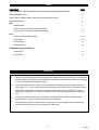
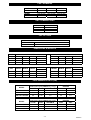
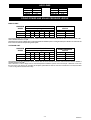
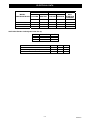
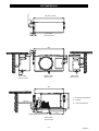
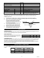
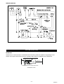
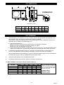
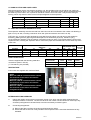
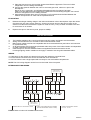
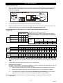
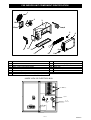
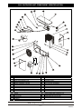
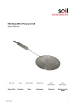
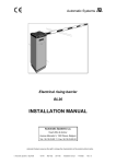
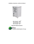
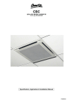
TECHNICAL MANUAL
CXE LOW TEMPERATURE SPLIT SYSTEMS
55908022-02
INDEX
CONTENTS
PAGE
PART NUMBERS, UNIT COMBINATIONS, OPTIONS, DIMENSIONS & WEIGHTS
3
PERFORMANCE DATA
3
AIR FLOWS, SOUND POWER AND SOUND PRESSURE LEVELS
4
ELECTRICAL DATA
5
CXE
DIMENSIONS
6
INSTALLATION: CONTENTS & PIPEWORK
7
ELECTRICAL: FUSES & WIRING DIAGRAMS
7-8
INSTALLATION: DIMENSIONS
8-9
PIPEWORK
9 - 10
CKC
ELECTRICAL
11
REFRIGERANT
12
COMPONENT IDENTIFICATION
CXE UNITS
13
CKC UNITS
14
GENERAL
1.
TEV Ltd recommend that personnel working on this equipment be skilled and fully conversant with
the appropriate Air Conditioning, Refrigeration and Electrical practices and have sound knowledge
of current Industrial Safe Working practices.
2.
CXE models are Electronic control units that use R407C refrigerant; they provide cooling within
the range of 2.3 – 5.0 kW. These units are matched with CKC outdoor units to complete a system.
CXE units are fitted with an expansion assembly, allowing the use of a liquid line. This can be
transferred to the outdoor unit, when an expansion line is required to accommodate longer pipe
runs.
3.
These units contain live electrical components, moving parts and refrigerant under pressure.
Always site out of reach of children and protect from vandalism.
4.
The data plate only gives information for the CXE unit. For system details add input power and
current of indoor and outdoor unit, including any heater load.
2/14
55908022-02
PART NUMBERS
MODEL
PART NUMBER
CXE 40
55900016
CXE 50
55900015
CXE 70
55900014
MODEL
PART NUMBER
CKC 20 1ph
55023720
CKC 40 1ph
55023741
CKC 60 1ph
55023740
UNIT COMBINATIONS
INDOOR UNIT
CXE 40
CXE 50
CXE 70
OUTDOOR UNIT
CKC 20
CKC 40
CKC 60
CXE OPTIONS
OPTIONAL KITS
DESCRIPTION
3kW heater
PART NUMBER
55900715
DIMENSIONS & WEIGHTS
MODEL
CX(E)
40
50
70
HEIGHT
483
483
483
UNPACKED
WIDTH DEPTH
845
320
845
320
845
320
CKC
HEIGHT
WIDTH
DEPTH
20
40
60
620
620
720
900
900
1000
310
310
310
WEIGHT
20
20
23
WEIGHT
1Ph
46
46
64
HEIGHT
530
530
530
PACKED
WIDTH DEPTH
950
370
950
370
950
370
HEIGHT
WIDTH
DEPTH
625
625
730
980
980
1080
340
340
340
WEIGHT
23
23
26
WEIGHT
1Ph
48
48
66
PERFORMANCE DATA (kW)
RATING CONDITIONS
MODEL
CXE 40 + CKC 20
CXE 50 + CKC 40
CXE 70 + CKC 60
(ROOM 5°Cdb/ 3°Cwb) (AMBIENT 27°C / 19°C)
TOTAL
SHR
SENSIBLE
2.3
3.5
5.0
0.85
0.80
0.70
2.0
2.8
3.5
RATING CONDITIONS
MODEL
CXE 40 + CKC 20
CXE 50 + CKC 40
CXE 70 + CKC 60
(ROOM 5°Cdb/ 3°Cwb) (AMBIENT 35°C / 19°C)
TOTAL
SHR
SENSIBLE
2.0
3.0
4.3
0.85
0.80
0.70
1.7
2.4
3.0
OPTIONAL ELECTRIC
HEATER
240V
230V
3.3
3.3
3.3
3.0
3.0
3.0
OPTIONAL ELECTRIC
HEATER
240V
230V
3.3
3.3
3.3
3.0
3.0
3.0
3/14
55908022-02
AIR FLOWS
MODEL
CXE 40
CXE 50
CXE 70
m³/s
0.61
0.66
0.58
MODEL
CKC 20
CKC 40
CKC 60
m³/s
0.81
0.72
0.78
SOUND POWER AND SOUND PRESSURE LEVELS
INDOOR UNIT
MAXIMUM
SPEED
CXE 40
CXE 50
CXE 70
125
69.1
71.7
70.1
SOUND POWER LEVELS
Frequency Hz
250
500
1K
2K
67.7 67.6 65.6 62.2
69.2 69.1 67.1 63.2
68.2 68.6 66.1 63.2
4K
56.0
58.5
57.5
SOUND PRESSURE
LEVELS
NC
dB(A)
55
48
56
50
56
49
Sound Power Levels were obtained in full accordance with the direct method of BS EN ISO3174:2000. Levels are shown in dB
with a standard reference of 1 pW.
Sound Pressure Levels in dB(A) refer to semi-hemispherical radiation (wall or ceiling mounted) at a distance of 1.5m from the
front of the unit, with the fan operating at full speed.
OUTDOOR UNIT
MAXIMUM
SPEED
CKC 20
CKC 40
CKC 60
125
77
77
73
SOUND POWER LEVELS
Frequency Hz
250
500
1K
2K
67
69
65
60
67
69
65
61
68
68
66
62
4K
54
54
54
SOUND PRESSURE
LEVELS
NC
dB(A)
49
44
49
44
50
45
Sound Power Levels were obtained in full accordance with the direct method of ISO 3741: 1988. Levels are shown in dB with a
standard reference of 1 pW.
Sound Pressure Levels in dB(A) refer to semi-hemispherical radiation (wall or floor mounted) at a distance of 3m from
the front of the unit, with the fan operating at full speed; (add 3dBA or 3NC for units at an intersection of a wall, add 1dBA
or 1NC for high level wall mounted units).
4/14
55908022-02
ELECTRICAL DATA
MODEL
INDOOR/OUTDOOR
CXE 40 + CKC 20
CXE 50 + CKC 40
CXE 70 + CKC 60
1 PH 230V 50Hz
FULL LOADS AMPS
COOLING
HEATING
COOLING
HEATING
kW
kW
AMPS
AMPS
SYSTEM
MAX.
STARTING
CURRENT
AMPS
1.3
2.1
2.4
3.1
3.1
3.1
7.15
10.2
9.8
12.8
13.8
13.8
28
50
61
INPUT POWER
UNIT ELECTRICAL LOADS [230V 50Hz 1Ph (A)
MODEL
CXE 40
CXE 50
CXE 70
FAN MOTOR
0.8
0.8
0.8
CKC
Fan motor
R407C compressor (1 Ph) nominal FLA
Crankcase heater
HEATER
13.0
13.0
13.0
20
0.6
6.9
0.25
40
0.6
10.2
0.25
60
0.6
9.8
0.25
5/14
55908022-02
888 (Fixing centers)
20
124 (Fixing centers)
CXE DIMENSIONS
17.5
39
TOP VIEW
(Ceiling Mounted)
888
39
17.5
124
96
60
320
120
MIN.
120
96
SIDE VIEW
(Ceiling mounted)
FRONT VIEW
SIDE VIEW
(Wall mounted)
(Wall mounted)
845
X
X
MIN. 500
FOR SIDE ACCESS
Z1
75
Z2
Z 1 = Suction
Z 2 = Liquid / Expansion
215
140
483
36
X = Interconnecting Wiring
70
35
65 TYP.
CONDENSATE DRAIN 22mm OD
422.5
REAR VIEW
(Wall mounted)
6/14
55908022-02
PARTS DESCRIPTION
Envelope containing operating instructions and
Declaration of Conformity
0.037" restrictor
(CXE 40 only)
0.051" restrictor
(CXE 50 only)
0.057" restrictor
(CXE 70 only)
Mounting brackets
Drain Stub/Nut/Gasket
Drain stub adaptor
Screw M5
Washer nylon
Washer M5 shakeproof
CONTENTS
QTY
Reducing flare nut 1/2” – 3/8”
ACTION
1
Pass to the end user.
1
1
1
2
1
1
6
6
6
Use with CKC 20 outdoor unit.
Use with CKC 40 outdoor unit.
Use with CKC 60 outdoor unit.
Use to hang unit.
Fitted by installer.
Convert to ¾" drain if required.
To fix brackets to unit.
To fix brackets to unit.
To fix brackets to unit.
Fit to liquid connection on the CXE 70 indoor unit
when matched with a CKC 60 outdoor unit
1
The unit may be mounted on a wall or solid ceiling using brackets supplied. It should be matched with the
appropriately sized outdoor unit; this instruction should be used in conjunction with the outdoor unit
installation instructions.
1.
2.
3.
4.
5.
6.
Fit all kits prior to installing the unit. (Heater kit is easier to fit when unit has been mounted).
Ensure that the mounting surface will support the operating weight of the unit (see table below).
Mark out the mounting positions and drill holes
to suit 6mm rawlbolt shields or equivalent
strength fasteners (ensure that the unit is
NUT
DRAIN TRAY
positioned to give sufficient access (min 0.5m)
to the electrics access side).
Fix the mounting brackets to the unit in the
GASKET
correct position for wall or ceiling mounting.
DRAIN STUB
Raise the unit into position and secure the
fixings, ensuring that it is square and level.
Remove the drain tray then fit the drain stub,
nut & gasket (Fig.1). Refit the drain tray.
Fig.1
CXE PIPEWORK
NITROGEN CHARGE
The unit contains a small charge of dry nitrogen, which should be discharged into the atmosphere. This is a
non-toxic, non-ozone depleting gas with no global warming potential.
PIPE CONNECTIONS
Pipework is terminated with 2 flare nuts & bonnets.
Access is via the rear right hand side. Pipes exit the
unit through holes in the back panel.
INDOOR UNIT
LIQUID / EXPANSION
SUCTION
CXE 40
3/8"
1/2 "
CXE 50
3/8"
1/2 "
CXE 70
1/2"
5/8"
CONDENSATE DRAIN
Push fit connections are widely available for the 7/8” (22mm) OD condensate drain and 3/4"(19mm) ID drain
stub adaptor. Alternatively 7/8” (22mm) bore plastic tubing may be fitted directly to the stub/adaptor with a
hose clamp. Take care not to over tighten hose clamps as this could damage the stub pipe.
Cables are routed to the terminal block via the cable cord grips at the rear of the unit and then through the
back of the electrics box (see page 2).
CXE ELECTRICAL CONNECTIONS
•
Cables MUST be size compatible with the recommended system fuse.
FUSES
WITH ELECTRIC
COOL ONLY
SYSTEM
HEATER
1PH
1PH
20A
20A
CXE 40
20A
20A
CXE 50
20A
32A
CXE 70
7/14
55908022-02
WIRING DIAGRAM
CKC INSTALLATION
MOUNTING
Whether floor or wall mounted, it is essential that the mounting surface is capable of supporting the unit
weight. Leave space around the unit for air circulation and access for installation and maintenance.
100 min
100 min
600 min
1500 min air off
Dimensions in mm.
8/14
55908022-02
CKC DIMENSIONS
(Dimensions in mm.)
MODEL
A
B
C
D
E
F
G
H
CKC 20
CKC 40
CKC 60
900
900
1000
300
300
300
560
560
660
525
525
570
185
185
213
60
60
60
333
333
333
308
308
308
CKC PIPEWORK
1.
Individual pipe runs to a maximum of 20m, including 7.5m lift, are permissible with liquid lines, 80m
with expansion lines, provided good refrigeration practice is followed.
Performance is based on 7.5m pipe runs. Correctly sized pipes for each installation will result in no
significant loss of capacity on extended pipe runs.
a) Pipe sizes are based on:Minimum of 3.8 m/s (750 fpm) suction gas velocity for horizontal or downflow.
Minimum of 7.6 m/s (1500 fpm) suction gas velocity for upflow.
Maximum of 15.2 m/s (3000 fpm) suction gas.
b) Where vertical risers exceed 3m, oil traps must be formed in the pipe. This will help ensure that oil
returns to the compressor. Typically fit an oil trap every 3m with a trap at the bottom of the riser.
2.
In calculating equivalent lengths of pipe runs, the effect of bends and fittings must be taken into
account. The table below covers the fittings most likely to be encountered in this installation.
The equivalent lengths of all the fittings in a pipe run should be added together and the total added to
the actual pipe length in order to calculate the total equivalent length.
3.
Use the shortest possible route, avoiding sharp bends.
4.
Completely insulate the suction line, fully over the indoor unit drain tray.
FITTING LOSSES, in equivalent straight lengths of pipe (m).
FITTING
45° Bend
90° Bend R/d = 1
90° Bend R/d = 1.5
180° Bend R/d = 1.5
180° Bend C/d = 2.5
90° Elbow
3/8"
0.12
0.37
0.24
0.73
0.46
0.67
1/2"
0.15
0.43
0.27
0.91
0.55
0.85
Pipe Size OD
5/8"
0.18
0.49
0.3
1.1
0.64
1.04
3/4"
0.21
0.55
0.37
1.28
0.76
1.25
7/8"
0.24
0.61
0.43
1.46
0.85
1.46
To calculate the total equivalent
length, the equivalent lengths of
all fittings in a pipe run must be
added to the actual length of pipe
in the run: these are the fittings
most likely to be used.
R = Radius of bend
d = Diameter of tube
C = Centres of bend
9/14
55908022-02
A. USING SUCTION AND LIQUID LINES:
With the expansion device connected to the indoor unit, the equivalent pipe run should be 20m maximum,
including a maximum lift of 7.5m. Fully insulate the suction line. Ensure the suction pipe is insulated well over
the drain tray at the indoor unit. Liquid lines should be routed to avoid hot areas. This prevents flash gas
forming, which may result in erratic control of liquid refrigerant to the evaporator.
MAXIMUM EQUIVALENT LENGTH OF SUCTION LINE PIPE SIZES (m) LIQUID LINE
SYSTEM
CXE40 + CKC20
CXE50 + CKC40
3/8"
1/2"
5/8"
-
1/4"
3/8"
7.5
-
20
15
20
-
20
-
-20
CXE70 + CKC60
-
7.5
18
20
-
20
B. USING SUCTION AND EXPANSION LINES
The expansion assembly must be removed from the indoor unit and connected to the outdoor unit allowing a
pipe run of up to 80m, including a maximum lift of 20m (CKC20 maximum 50m with 7.5m lift).
CXE units only, remove the right hand panel cover plate from the indoor unit and remove the expansion
assembly. [Make good the gap using Extended Pipe Run Kit 55900709 (30,40,50), 55900710 (70).]
Fit the expansion assembly onto the outdoor unit liquid line service valve. Fully insulate both the suction and
expansion lines, including the expansion device: ensure the pipes are insulated well over the drain tray at the
indoor unit.
SYSTEM
CXE40 + CKC20
CXE50 + CKC40
MAXIMUM EQUIVALENT LENGTH OF SUCTION LINE PIPE
SIZES (m)
3/8"
1/2"
5/8"
3/4"
7/8”
7.5
23
50
10
36
80
-
CXE70 + CKC60
-
7.5
18
50
3/8"
1/2"
5/8"
CHARGE
(kgs) AT
7.5m
50
7.5
80
-
0.93
1.30
7.5
50
80
1.90
EXPANSION LINES
80
PIPE CONNECTIONS
Units are supplied with the following male flare
connections (sizes in inches):
(** Use reducing nut provided)
OUTDOOR UNIT
CKC20
CKC40
CKC60**
LIQUID / EXPANSION
3/8"
3/8"
3/8"
SUCTION
1/2"
1/2"
5/8"
RESTRICTORS
Indoor units are supplied with restrictors fitted.
NOTE
When the CXE 40 is matched with a CKC 20.
The restrictor in the indoor unit must be
changed to 0.033"
When the CXE 50 is matched with a CKC 40.
The restrictor in the indoor unit must be
changed to 0.051"
When the CXE 70 is matched with a CKC 60.
The restrictor in the indoor unit must be
changed to 0.057"
INTERCONNECTING PIPEWORK
1.
Indoor and outdoor units have a low pressure charge of N2, which may be safely released into the
atmosphere before connection. The service valves on the outdoor unit should remain closed (IN, fully
clockwise) until pipework has been fitted, to avoid unnecessary moisture ingress.
2.
Connecting the pipework
a. Remove the flare nuts from the suction and liquid service valves.
b. Ensure that the suction line is fully insulated: if an expansion line is used this should also be fully
insulated.
10/14
55908022-02
c. Place the flare nuts over the incoming pipework and flare the pipe ends. The use of a little
refrigeration oil on the flaring tool will help.
d. Connect the pipework between the units. Do not leave pipe ends, valves etc. open to the
atmosphere.
R407C is very hygroscopic, and will absorb damaging levels of moisture if left open.
Always use two spanners when tightening the flare nuts to avoid twisting the pipes. Use a small
amount of refrigerant oil on the mating surfaces.
e. Sight glasses and filter driers are not necessary, but if required should be fitted between the
outdoor unit liquid shut off valve and the expansion device.
EVACUATING
1.
Release the nitrogen holding charge in the indoor and outdoor units to atmosphere. Open the valves
(hex drive fully out) using a 5mm Allen key. Connect a vacuum pump to the service ports on the
outdoor unit valves and evacuate the system to 1000 microns (1 Torr) or better and allow to be held
for a minimum of 15 minutes.
2.
Replace the caps on the service ports, (torque to 25NM).
CKC ELECTRICAL
The installer supplies mains, control and interconnecting cables: equipment must be earthed.
Wiring must be carried out in accordance with local and national codes.
Mains supply cables must be size compatible with the recommended fuse (see indoor unit instruction
for system fuse size).
An all pole isolator switch should be positioned within easy reach of the indoor/outdoor unit dependant
on which receives the fuse supply.
Cable clamps for use with stranded cables are supplied and should be used to secure
incoming/outgoing cables. Installers must supply a method of securing solid sheathed cables.
WIRING
Cable entry for the outdoor unit electrics is through the cabinet to a terminal block.
Ensure that all connections are secure and that both units are earthed.
CKC fan motors have a single speed and are ready for use at all outdoor temperatures.
NOTE: The CKC wiring diagram can be found on the inside of the front panel.
INTERCONNECTING WIRING
FUSED SUPPLY
230V 1PH 50 Hz)
REFRIGERANT
3
L
N
PE
3
L
N
PE
CU
L
N
PE
CU
L
N
PE
CXE
CXE
FUSED SUPPLY
230V 1PH 50 Hz)
POWER CABLE TO SUIT SUPPLY FUSE
CABLE TO SUIT INDOOR UNIT LOADING
(ALLOW FOR HEATER LOAD IF FITTED)
CABLE FOR CONTROL CIRCUIT
0.75 mm² - 2.5 mm²
FUSES: Refer to indoor unit installation instructions.
11/14
55908022-02
CKC REFRIGERANT
ADDING REFRIGERANT
1.
The unit is fitted with head pressure control; before charging, isolate the outdoor unit and transfer the
motor wire on the head pressure control from terminal 4 to terminal 1. (Don't forget to transfer it
back after charging).
1 2 3 4
444
☺
BLUE MOTOR WIRE
☺
4
HPC
2.
If a manual HP cut-out is fitted, ensure that the reset button is depressed.
3.
A 3 minute delay occurs between successive compressor operations.
4.
R407C should be introduced through the Schrader valve on the indoor unit, or the service port on the
suction service valve on the outdoor unit. No other refrigerant must be used.
NOTE: LABEL R407C POE (supplied loose) TO BE FIXED ABOVE SERVICE VALVES.
CHARGE (g)
LIQUID LINE (m)
SYSTEM
5
10
15
20
No extra POE oil needed with liquid lines.
Charges shown are for guidance: actual charge will depend on
the individual application. It is recommended that you charge to a
sweat line on the outlet of the evaporator and/or a full sight glass
if fitted.
CXE 40 + CKC 20 780 1080 1380 1680
R407C CXE 50 + CKC 40 1150 1450 1750 2050
CXE 70 + CKC 60 1750 2050 2350 2650
Additional
charge
based
on:-
Liquid line
Expansion line
1/4"
3/8"
3/8"
1/2"
5/8"
25 g/m
60 g/m
16 g/m
30 g/m
48 g/m
EXPANSION LINE (m)
SYSTEM
5
10 15 20 25 30 35 40 45 50 55 60 65 70 75 80
CXE 40 + CKC 20 890 970 1050 1130 1280 1430 1580 1730 1880 2030 R407C CXE 50 + CKC 40 1260 1340 1490 1640 1790 1940 2090 2330 2570 2810 2960 3110 3260 3410 3560 3710
CXE 70 + CKC 60 1860 1940 2090 2240 2390 2540 2690 2840 2990 3140 3380 3620 3860 4100 4340 4580
POE
OIL
(EXP.
LINE)
CXE 40 + CKC 30
CXE 50 + CKC 50
-
-
-
-
25
50
25
50
25
50
50
50
50 50
100 100 100 100 100 150 150 150
CXE 70 + CKC 80
-
-
-
-
50
50
100 100 100 150 150 150 200 200 200 250
5.
Run the system for a few minutes to allow it to stabilize. Where possible, charge to a sweat line on the
evaporator. Typical suction pressure on short lines at UK conditions should be approx. 3.8bar (55
psig).
6.
Transfer the motor wire back from terminal 1 to 4 on the HPC pcb.
7.
Head pressure controller
The HPC is factory set to suit R407C refrigerant. It may be necessary to adjust this to suit site
conditions, to raise or lower the nominal head pressure.
I.
With the system switched off, connect a high pressure gauge to the liquid line service valve.
II.
Switch on the system, indoor fan set to high speed and run for a few minutes to stabilise.
III.
The head pressure should be approximately 275-280 psig (18.9-19.6 barg). To achieve this
adjust the screw clockwise to increase the pressure by approx 5 psig (0.5barg)
NOTE: Min fan speed (0 rpm) and fan cut in pressure (230psig / 15.6 barg) are factory set and not
adjustable.
12/14
55908022-02
CXE INDOOR UNIT COMPONENT IDENTIFICATION
1
2
3
14
4
15
5
13
10
11
9
Grille
Fan / motor
Case
Wall / ceiling mounting brackets
Heater bracket
Coil assembly
Thermostat bulb & bracket
Restrictor assembly / extended pipe (option)
9
10
11
12
13
14
15
De-ice stat
Heater assembly (option)
Drain stub adaptor
Drain tray
Side access panel
Electrics box door
Controller
INSIDE VIEW OF ELECTRICS BOX
N
Mains Cable Entry
Point
L
MAINS IN
E
L
CU OUT
E
CU
SPARE
1
2
3
4
5
6
7
8
7
8
12
N
4
6
Capillary Entry
Internal Earth
Terminal
Switch
Incoming Fan
Wires
Capacitor
De - Ice
Thermostat
Controller
Transformer
13/14
55908022-02
CKC OUTDOOR UNIT COMPONENT IDENTIFICATION
1
2
3
4
5
6
7
8
9
10
11
12
13
14
15
16
17
LID
CONTACTOR
OVERLOAD
HEAT EXCHANGER COIL
REAR ACCESS PANEL
MAINS TERMINAL COVER
FAN CAPACITOR
BULKHEAD PANEL
HP SWITCH (MANUAL, OPTION)
SERVICE VALVE (LIQUID)
SERVICE VALVE (SUCTION)
VALVE PANEL
BASE
MOUNTING FOOT
LP SWITCH
COMPRESSOR
HANDLE
18
19
20
21
22
23
24
25
26
27
28
29
30
31
32
33
FRONT ACCESS
FAN GUARD
FASCIA PANEL
CORNER PANEL
SUPPORT BRACKET
FAN / MOTOR ASSEMBLY
END CLAMP
TERMINAL
FUSE
FUSE TERMINAL
TERMINAL (4 WAY)
EARTH TERMINAL
HEAD PRESSURE CONTROL pcb
3 MINUTE TIMER pcb
COMPRESSOR CAPACITOR
ELECTRICS BOX
TEV LTD, ARMYTAGE ROAD, BRIGHOUSE, WEST YORKSHIRE, HD6 1QF. TEL: + 44 (0) 1484 405600 FAX: +44 (0) 1484 405620
EMAIL: [email protected] WEB: www.marstair.com
14/14
55908022-02