1
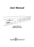
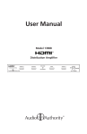
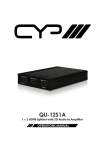
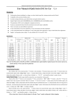
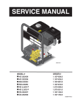
User Manual
DATE
3/��/08
LTR REVISION RECORD
A
AUTH
Release
DR
CK
DAF
MMC-CLUX21AP-UTE
1T-SX-632
Model 1372A
2X1 Switcher
v1.3
v1.3
1
2
1
2
2x1 SWITCHER
INPUT
ENHANCE
POWER
INPUT
ENHANCE
POWER
Model 1372A and 1374A
HDMI Switchers
MMC-CLUX21AP-LTE
HDMI OUT
HDMI IN
5V DC
2
1
RS-232
�����������
�����
����
1372A
�����
CLUX-21AP(TVONE)
MMC-CLUX21AP-UTE
MMC-CLUX21AP-LTE
2008.03.03
陳秋文
����
1:1
3/��/08
��������
DAF
�������
膜
1372A Front and Back Artwork
�����������
NA
���������
1/1
����
A
Table Of Contents
1.0
Introduction . . . . . . . . . . . . . . . . . . . . . . . 3
2.0
Getting the Best Results . . . . . . . . . . . . . . . . . 4
3.0
Checking Package Contents . . . . . . . . . . . . . . . 4
4.0
Connecting The Hardware
5.0
Operating the Unit . . . . . . . . . . . . . . . . . . . . 6
6.0
Troubleshooting . . . . . . . . . . . . . . . . . . . . . 8
7.0
Specifications . . . . . . . . . . . . . . . . . . . . . . . 9
8.0
Limited Warranty . . . . . . . . . . . . . . . . . . .
10
9.0
Regulatory Compliance . . . . . . . . . . . . . . . .
11
10.0 Contact Information . . . . . . . . . . . . . . . . . .
11
. . . . . . . . . . . . . . . 5
Liability Statement
Every effort has been made to ensure that this product is free of defects. Audio Authority
cannot be held liable for the use of this hardware or any direct or indirect consequential
damages arising from its use. It is the responsibility of the user of the hardware to check
that it is suitable for his/her requirements and that it is installed correctly. All rights reserved.
No parts of this manual may be reproduced or transmitted by any form or means electronic
or mechanical, including photocopying, recording or by any information storage or retrieval
system without the written consent of the publisher.
Audio Authority reserves the right to revise any of its hardware and software following its
policy to modify and/or improve its products where necessary or desirable. This statement
does not affect the legal rights of the user in any way.
Audio Authority and the Double-A Symbol are registered trademarks of Audio Authority
Corp. Copyright April, 2006, all rights reserved. All third party trademarks and copyrights
are recognized.
Dolby and Dolby Digital are trademarks of Dolby Laboratories, Incorporated.
DTS is a registered trademark of DTS, Inc.
HDMI, the HDMI logo and High-Definition Multimedia Interface are trademarks or registered
trademarks of HDMI Licensing LLC.
2
1.0 INTRODUCTION
Thank you for purchasing this HDMI switcher from Audio Authority. The
Model 1372A and 1374A switchers are designed to allow selection of 2
or 4 inputs respectively for display on an HDMI compliant television or
signal distribution system. These version 1.3 HDMI switchers support all
standard HDTV formats, PC formats from 1024x768 through 1920x1200,
and embedded HD-Audio. The switchers can be controlled via the front
panel, the included infrared remote control and/or RS-232 control.
Audio Authority also offers an extensive line of audio and video
switchers, converters and distribution amps available for purchase online
at www.audioauthority.com.
1.1 FEATURES
• HDMI 1.3, HDCP 1.1 and DVI 1.0 compliant
• Allows switching of 2 or 4 inputs
• Supports 10/12 bit color depth display
• PC resolutions through 1920x1200
• HDTV resolutions through 1080p@60Hz
• SDTV resolutions 480i and 576i
• Supports embedded high bit rate audio: Audio Dolby® Digital TrueHD,
DTS-HD, and LPCM
• Signal enhancement feature enables longer cable runs
• Accepts HDMI locking cables
• Infrared remote control included
• RS-232 control capable
3
2.0 GETTING THE BEST RESULTS
Many factors influence the quality and reliability of HDMI switcher
installations. Consider the following and take basic precautions
suggested below to ensure the best possible performance.
• Output display device. The quality of the output signal depends
largely upon the type and quality of the HDMI display device used;
some televisions simply look better than others.
• Distance between the sources and the display. Long distances are
possible, but premium quality cables and advanced HDMI extenders
with DDC correction may be necessary for the longest runs.
• Input/output connection cables. HDMI cable design and quality
are extremely important in long cable runs where capacitance can
severely degrade performance. Cables should be of the best quality;
low quality cables are susceptible to interference. Always use locking
cables or good strain relief methods to prevent cables from becoming
loose over time.
• Interference from nearby electrical devices can have an adverse
effect on signal quality. For example, older computer monitors often
emit a very high electromagnetic field that can interfere with the
performance of video equipment in its proximity.
3.0 CHECKING PACKAGE CONTENTS
Before attempting to use this switcher, please check the packaging and
make certain the following items are contained in the shipping carton:
• HDMI Switcher
• Infrared Remote Control
• 5 VDC Power Adapter
• User Manual
Note: please keep the original packing material in case the unit ever needs to be
returned. If you find any items are missing, contact Audio Authority immediately. Have
the model number and invoice available for reference when you call.
4
4.0 CONNECTING THE HARDWARE
Please study the front and rear panel drawings and become familiar with
the signal input, outputs and power input.
MRN-CLUX41AP-1AA
Model 1374A
4X1 Switcher
1
2
3
4
INPUT
ENHANCE
POWER
MRN-1TSX634-2
HDMI OUT
5V DC
HDMI IN
4
3
2
1
RS-232
• Connect HDMI approved cables from the HDMI sources to the inputs
of the switcher. Cable length can be up to 30 meters – preferably
shorter.
• Connect the output
of the switcher2008.03.20
to the destination device using
CLUX-41AP(AA)
HDMI approvedMRN-CLUX41AP-1AA
cables
no
more
than
30 meters1:1long.
陳秋文
MRN-1TSX634-2
• Connect the power adapter to the AC source and then to the switcher.
• Turn on the HDMI sources and HDMI destination device
• Turn on the switcher by pressing the power button on the front panel
or on the IR remote control, or use an RS-232 command. Observe the
source signals on the input of the destination device. The switcher’s
front panel LEDs indicate the active input.
• Make certain that the HDMI cables are securely plugged into the
source and display devices as well as the HDMI switcher. Always use
high quality cables, and the shortest length possible, for best results.
Note: Proper operation of HDMI distribution amplifiers depends on the
use of high quality HDMI cables that provide low loss, high bandwidth
signal handling. The distance specification cannot be guaranteed unless
cables used throughout the system meet these high standards.
5
4.1 Using the Locking Cable Securing Feature
If HDMI cables are used that are equipped with locking type connectors,
remove the Philips head screws from the rear of the unit just above the
HDMI connectors and replace them with the hex jackscrews included
with the accessory pack. After screwing these into the threaded holes
vacated by the Philips head screws, the jackscrew provides a threaded
receptacle for the screw that is part of the locking HDMI connector on the
cable. Plug in the cable’s locking HDMI connector and secure it to the
unit with its integral screw.
5.0 OPERATING THE UNIT
5.1 Front Panel Controls
• Enhance Switch
If the cable run length is excessive and the quality of the display is
less than optimum, press the Enhance switch on the front panel. The
switcher’s low noise amplifier may allow the system to work with longer
input and output cables if there is enough signal for the amplifier to
recover the HDMI bitstream. An LED indicates that the amplifier is in
use.
• Input Select Switch
This switch is pressed to select the desired input. Each time the switch
is pressed, the next input in sequence (from left to right) is selected.
LED displays indicate which input is active.
• On/Off Power Switch
Use this switch to turn the unit on or off, or use the IR remote control
or RS-232 command. An indicator LED shows when the unit is turned
on.
5.2 IR Remote Control
• The unit can be turned on and off and the
inputs can be selected simply by pressing the
appropriate button on the remote.
• Selection of Enhance mode is not possible from
the IR Remote.
• Note: When unpacking the HDMI switcher,
remove the insulator from the battery
compartment of the remote in order for the remote
to receive power. The battery compartment slides
out from the bottom of the unit.
6
POWER
1
2
3
4
5.3 Switcher Operation via RS-232 Machine Control
The 1372 and 1374 HDMI Switchers may be operated using RS-232
protocols. The technical information needed is provided in the two charts
below. A system using RS-232 control should be wired and programmed
by a qualified custom integrator.
Pin Definitions
HDMI Switcher
PIN
1
2
3
4
5
6
7
8
9
Definition
NC
Tx
Rx
NC
GND
NC
NC
NC
NC
Control Unit
PIN
1
2
3
4
5
6
7
8
9
5.2.1 RS-232 Commands
Command
“I” + “1”
“I” + “2”
“I” + “3”
“I” + “4”
“S” + “1”
“S” + “0”
“P” + “1”
“P” + “0”
Action
Port 1 On
Port 2 On
Port 3 On
Port 4 On
Enable Signal Enhance
Disable Signal Enhance
Power On
Power Off
7
Definition
NC
Rx
Tx
NC
GND
NC
NC
NC
NC
6.0 TROUBLESHOOTING
• For higher resolutions such as 1080p, first make certain that the input
cable is as short as possible and none of the output cables are more
than 15 meters long. HDMI cable design and quality are extremely
important in long cable runs where capacitance can severely effect
performance. Our 1391A Extender/DDC Corrector may be a necessary
accessory to use in extreme length applications.
• Make certain that the switcher is receiving power by looking at the
power LED. It should be illuminated and not flickering on and off.
Intermittent operation generally means a problem with the DC power
adapter or low AC voltage being applied to the DC adapter’s input.
• If you still experience problems using the switcher, you should attempt
to determine what is wrong by first attaching each source device in
turn directly to the destination device using the same cables you are
using with the expanded system. This is a way of determining if the
problem is due to bad cables or a problem with the other devices. If
you are unable to obtain a signal using this simplified path, suspect the
cables, the source device or the destination device.
• Remember that HDMI devices communicate with one another so the
source device and all destination devices must be fully HDMI capable
and HDCP compliant.
If a problem still persists after trying the above suggestions, contact the
Audio Authority Technical Service department via email:
[email protected], or call 800-322-8346 or 859-233-4599.
8
7.0 SPECIFICATIONS
Video Inputs
1372A
2x HDMI via Type A HDMI Connector
1374A
4x HDMI via Type A HDMI Connector
Video Output
Both Models
1x HDMI via Type A HDMI Connector
General
Frequency Bandwidth
2.25Gbps (Single Link)
Color Depth
10/12 bit color depth display
Supported PC Resolution
Up to 1920x1200
Supported TV Formats
480i, 480p, 576i, 576p, 576p, 720p, 1080i and 1080p
Audio I/O (Embedded)
HD-Audio, including Dolby® TrueHD & DTS-HD
Compliance
HDMI V1.3, HDCP V1.1, DVI V1.0
Signal Enhancement
Switchable on/off
Maximum Distances
Source to Switcher
20m (60’) for 1080p/8-bit, 15m (45’) for 1080p/12-bit
Switcher to Display
15m (45’) for 1080p/8-bit, 10m (30’) for 1080p/12-bit
Control Methods
Local Control
Front panel via push button switches
Remote Control
Infrared and RS-232 via DB-9 connector
Warranty
Limited Warranty
1 Year parts and labor
Mechanical
Size (H-W-D)
1.2”x7.9x3.5” (30x200x89mm)
Weight (Net)
1.88lbs (0.85kg)
Environmental
Operating Temperature
0° to +50°C (+32° to +122°F)
Operating Humidity
10% to 90%, non-condensing
Storage Temperature
-10° to +50°C (+32° to +122°F)
Storage Humidity
10% to 90%, non-condensing
Regulatory Approvals
HDMI Switchers
FCC, CE, RoHS
Power Supply
UL, CUL, CE, PSE, GS, RoHS
Accessories Included
AC Power Adapter External Power Supply 5VDC@2A
Instruction Manual
IR Remote Control
Product Model Numbers
1372A
2x1 HDMI Switcher
1374A
4x1 HDMI Switcher
9
8.0 LIMITED WARRANTY
If any consumer product from Audio Authority fails due to defects in
materials or workmanship within one year from the date of the original
sale to the end-user, Audio Authority guarantees that we will replace the
defective product at no cost. Freight charges for the replacement unit will
be paid by Audio Authority (Ground service only). A copy of the invoice
showing the item number and date of purchase (proof-of-purchase)
must be submitted with the defective unit to constitute a valid in-warranty
claim.
Units that fail after the warranty period has expired may be returned to
the factory for repair at a nominal charge, if not damaged beyond the
point of repair. All freight charges for out-of-warranty returns for repair are
the responsibility of the customer. Units returned for repair must have a
Return Authorization Number assigned by the factory.
This is a limited warranty and is not applicable for products which, in our
opinion, have been damaged, altered, abused, misused, or improperly
installed. Audio Authority makes no other warranties either expressed
or implied, including limitation warranties as to merchantability or fitness
for a particular purpose. Additionally, there are no allowances or credits
available for service work or installation performed in the field by the end
user.
8.1 Warranty Service Procedures
If you suspect a product defect, contact Audio Authority’s Technical
Service Department at 800-322-8346 or 859-233-4599 for assistance
in verifying the problem. If a defect or potential defect is suspected, a
replacement unit will be shipped immediately on a defect-exchange basis
and a Return Authorization Number will be issued for the return of the
defective product. Replacement units are sent out at the Manufacturer’s
Suggested Retail Price which is debited to the Customer’s Credit
Card at the time of shipment. Once we receive the defective unit
back at the factory, it will be evaluated under the conditions of this
warranty and if found to be in-warranty, a full credit will be issued to the
Customer’s Credit Card. Return freight charges for the defective unit
are the customer’s responsibility. Please contact our Technical Service
Department for complete details concerning all in and out of warranty
service matters.
We appreciate your confidence in our products and services and will
always strive to meet or exceed your needs.
10
9.0 REGULATORY COMPLIANCE
The 1372A, and 1374A switchers have been tested for compliance
with appropriate FCC and CE rules and regulations and are also RoHS
compliant.
The power adaptor/supplies have been tested for compliance with UL,
CE and CSA rules and regulations and are also RoHS compliant.
10.0 CONTACT INFORMATION
Should you have questions or require assistance with this product in
areas not covered by this manual, please contact Audio Authority using
the information below.
Audio Authority Technical Service
800-322-8346 M-F 8:30 AM to 5:00 PM, EST
International: 859-233-4599 Fax: 859-233-4510
Send email to: [email protected]
Audio Authority Corporation
2048 Mercer Road
Lexington, Kentucky 40511-1071
USA
11
2048 Mercer Rd., Lexington, KY 40511-1071
Phone: 859-233-4599 • Fax: 859-233-4510
Toll-Free USA & Canada: 800-322-8346
Website: www.audioauthority.com
E-069
4/08