1
CYLINDER UNIT
January 2013
No. OCH531
REVISED EDITION-A
SERVICE MANUAL
R410A
[Model name]
[Service Ref.]
EHST20C-VM6HB
EHST20C-VM6HB.UK
EHST20C-YM9HB.UK
EHST20C-TM9HB.UK
EHST20C-VM2B.UK
EHST20C-VM6B.UK
EHST20C-YM9B.UK
EHST20C-VM6EB.UK
EHST20C-YM9EB.UK
EHST20C-VM6SB.UK
EHPT20X-VM2HB.UK
EHPT20X-VM6HB.UK
EHPT20X-YM9HB.UK
EHPT20X-TM9HB.UK
EHPT20X-VM6B.UK
EHPT20X-YM9B.UK
EHST20C-YM9HB
EHST20C-TM9HB
EHST20C-VM2B
EHST20C-VM6B
EHST20C-YM9B
EHST20C-VM6EB
EHST20C-YM9EB
EHST20C-VM6SB
EHPT20X-VM2HB
EHPT20X-VM6HB
EHPT20X-YM9HB
EHPT20X-TM9HB
EHPT20X-VM6B
EHPT20X-YM9B
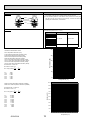
Revision:
• EHST20C-TM9HB.UK,
EHST20C-VM2B.UK and
EHPT20X-TM9HB.UK
have been added in
REVISED EDITION-A.
• Some descriptions have
been modified.
• Please void OCH531.
Note:
• This manual describes
only service data of cylinder unit.
• RoHS compliant products
have <G> mark on the
spec name plate.
CONTENTS
1. REFERENCE MANUAL ................................... 2
2. SAFETY PRECAUTION................................... 3
3. SPECIFICATIONS ............................................ 6
4. PART NAMES AND FUNCTIONS .................. 7
5. OUTLINES AND DIMENSIONS ..................... 10
6. WIRING DIAGRAM ......................................... 11
7. FIELD WIRING ............................................... 27
8. WATER SYSTEM DIAGRAM ......................... 31
9. CONTROLS ................................................... 36
10. TROUBLESHOOTING ................................... 56
11. DISASSEMBLY PROCEDURE ...................... 72
12. SUPPLEMENTARY INFORMATION ............. 88
CYLINDER UNIT
MAIN CONTROLLER
13. SERVICE AND MAINTENANCE ................... 89
PARTS CATALOG (OCB531)
1
REFERENCE MANUAL
OUTDOOR UNIT'S SERVICE MANUAL
Service Ref.
Service Manual No.
PUHZ-RP35/50/60/71VHA4
PUHZ-RP35/50/60/71VHA4R4
PUHZ-RP100/125/140VKA
OCH451
PUHZ-RP100/125/140YKA
PUHZ-RP100/125YKAR4
PUHZ-HRP71/100VHA
PUHZ-HRP71/100VHA2
PUHZ-HRP71/100VHA2R1
PUHZ-HRP100VHA2R2
OCH425
PUHZ-HRP100/125YHA
PUHZ-HRP100/125YHA2
PUHZ-HRP100/125YHA2R1
PUHZ-W50/85VHA(-BS)
PUHZ-W50/85VHAR1(-BS)
OCH439
PUHZ-W50VHAR2(-BS)
PUHZ-W85VHA2.UK
PUHZ-W85VHA2-BS.UK
OCH465
PUHZ-HW112/140YHA(-BS)
PUHZ-HW112/140YHA2(-BS)
PUHZ-HW112/140YHA2R1(-BS)
PUHZ-HW112/140YHA2R3(-BS)
PUHZ-HW140VHA(-BS)
OCH439
PUHZ-HW140VHA2(-BS)
PUHZ-HW140VHA2R1(-BS)
PUHZ-HW140VHA2R2-BS
PUHZ-HW140VHA2R3(-BS)
PUHZ-SW40/45VHA(-BS)
PUHZ-SW75/100/120VHA(-BS)
PUHZ-SW100/125YHA(-BS)
PUHZ-SHW80/112VHA
PUHZ-SWH112/140YHA
OCH531A
OCH525
OCH533
OCH526
2
2
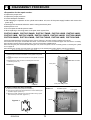
SAFETY PRECAUTION
Please read the following safety precautions carefully.
WARNING:
Precautions that must be observed to prevent injuries or death.
CAUTION:
Precautions that must be observed to prevent damage to unit.
Mitsubishi Electric is not responsible for the failure of locally-supplied and field-supplied parts.
• Be sure to perform periodical maintenance.
• Be sure to follow your local regulations.
• Be sure to follow the instructions provided in this manual.
WARNING
Mechanical
The cylinder unit and outdoor unit must not be installed, disassembled, relocated, altered or repaired by the user. Ask an authorised installer or technician. If the
unit is installed improperly or modified after installation by the user, water leakage, electric shock or fire may result.
The outdoor unit should be securely fixed to a hard level surface capable of bearing its weight.
The cylinder unit should be positioned on a hard level surface capable of supporting its filled weight to prevent excessive sound or vibration.
Do not position furniture or electrical appliances below the outdoor unit or cylinder unit.
The discharge pipework from the emergency devices of the cylinder unit should be installed according to local law.
Only use accessories and replacement parts authorised by Mitsubishi Electric ask a qualified technician to fit the parts.
Electrical
All electrical work should be performed by a qualified technician according to local regulations and the instructions given in this manual.
The units must be powered by a dedicated power supply and the correct voltage and circuit breakers must be used.
Wiring should be in accordance with national wiring regulations. Connections must be made securely and without tension on the terminals.
Earth unit correctly.
General
Keep children and pets away from both the cylinder unit and outdoor unit.
Do not use the hot water produced by the heat pump directly for drinking or cooking. This could cause illness to the user.
Do not stand on the units.
Do not touch switches with wet hands.
Annual maintenance checks on both the cylinder unit and the outdoor unit should be done by qualified person.
Do not place containers with liquids in on top of the cylinder unit. If they leak or spill onto the cylinder unit damage to the unit and/or fire could occur.
Do not place any heavy items on top of the cylinder unit.
When installing or relocating, or servicing the cylinder unit, use only the specified refrigerant (R410A) to charge the refrigerant lines. Do not mix it with any other
refrigerant and do not allow air to remain in the lines. If air is mixed with the refrigerant, then it can be the cause of abnormal high pressure in the refrigerant
line, and may result in an explosion and other hazards.
The use of any refrigerant other than that specified for the system will cause mechanical failure or system malfunction or unit breakdown. In the worst case, this
could lead to a serious impediment to securing product safety.
In heating mode, to avoid the heat emitters being damaged by excessively hot water, set the target flow temperature to a minimum of 2ºC below the maximum
allowable temperature of all the heat emitters. For Zone2, set the target flow temperature to a minimum of 5ºC below the maximum allowable flow temperature
of all the heat emitters in Zone2 circuit.
CAUTION
Use clean water that meets local quality standards on the primary circuit.
The outdoor unit should be installed in an area with sufficient airflow according to the diagrams in the outdoor unit installation manual.
The cylinder unit should be located inside to minimise heat loss.
Water pipe-runs on the primary circuit between outdoor and indoor unit should be kept to a minimum to reduce heat loss.
Ensure condensate from outdoor unit is piped away from the base to avoid puddles of water.
Remove as much air as possible from the primary and DHW circuits.
Refrigerant leakage may cause suffocation. Provide ventilation in accordance with EN378-1.
Be sure to wrap insulation around the piping. Direct contact with the bare piping may result in burns or frostbite.
Never put batteries in your mouth for any reason to avoid accidental ingestion.
Battery ingestion may cause choking and/or poisoning.
Install the unit on a rigid structure to prevent excessive sound or vibration during operation.
Do not transport the cylinder unit with water inside the DHW tank or coil. This could cause damage to the unit.
If power to the cylinder unit is to be turned off (or system switched off) for a long time, the water should be drained.
If unused for a long period, before operation is resumed, DHW tank should be flushed through with potable water.
Preventative measures should be taken against water hammer, such as installing a Water Hammer Arrestor on the primary water circuit, as directed by the manufacturer.
OCH531A
3
WARNING (SPLIT MODELS ONLY)
Do not discharge refrigerant into the atmosphere if refrigerant leaks during installation, ventilate the room.
Use appropriate tools for high pressure refrigerant.
When pumping down refrigerant , stop the compressor before disconnecting the refrigerant pipes.
During installation securely fasten the refrigerant pipes before starting the compressor.
Check that refrigerant gas does not leak after the completion of installation.
Use R410A refrigerant only. Do not allow air to enter the lines. Failure to observe these instructions will cause mechanical failure, system failure or, in the worst
case, serious breach of product safety.
CAUTION (SPLIT MODELS ONLY)
<Using R410A refrigerant heat pumps>
Use C1220 copper phosphorus, for copper and copper alloy seamless pipes, to connect the refrigerant pipes. Make sure the insides of the pipes are clean and
do not contain any harmful contaminants such as sulfuric compounds, oxidants, debris, or dust. Use pipes with the specified thickness. (Refer to section 4.5. in
the installation manual.) Note the following if reusing existing pipes that carried R22 refrigerant.
- Replace the existing flare nuts and flare the flared sections again.
- Do not use thin pipes. (Refer to section 4.5 in the installation manual.)
Store the pipes to be used during installation indoors and keep both ends of the pipes sealed until just before brazing. (Leave elbow joints, etc. in their packaging.) If dust, debris, or moisture enters the refrigerant lines, oil deterioration or compressor breakdown may result.
Use ester oil, ether oil, alkylbenzene oil (small amount) as the refrigeration oil applied to the flared sections. If mineral oil is mixed in the refrigeration oil, oil deterioration may result.
Do not use refrigerant other than R410A refrigerant. If another refrigerant is used, the chlorine will cause the oil to deteriorate.
Use the following tools specifically designed for use with R410A refrigerant. The following tools are necessary to use R410A refrigerant. Contact your nearest
dealer for any questions.
Tools (for R410A)
Gauge manifold
Charge hose
Gas leak detector
Torque wrench
Flare tool
Size adjustment gauge
Vacuum pump adapter
Electronic refrigerant charging scale
Be sure to use the correct tools. If dust, debris, or moisture enters the refrigerant lines, refrigeration oil deterioration may result.
Do not use a charging cylinder, a cylindrical measuring container, when charging R410A refrigerant gas. If the refrigerant gas is transferred to a charging cylinder,
the composition of the refrigerant will change and system efficiency will be reduced.
OCH531A
4
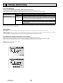
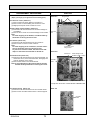
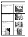
[1] Cautions for service
(1) Perform service after recovering the refrigerant left in unit completely.
(2) Do not release refrigerant in the air.
(3) After completing service, charge the cycle with specified amount of refrigerant.
(4) When performing service, install a filter drier simultaneously.
Be sure to use a filter drier for new refrigerant.
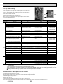
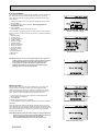
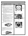
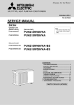
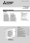
[2] Additional refrigerant charge
When charging directly from refrigerant cylinder
· Check that cylinder for R410A on the market is syphon type.
· Charging should be performed with the refrigerant cylinder of syphon stood vertically. (Refrigerant is charged from liquid
phase.)
Unit
Gravimeter
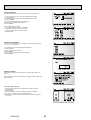
[3] Service tools
Use the service tools below as exclusive tools for R410A refrigerant.
No.
Tool name
1
Specifications
· Only for R410A
Gauge manifold
· Use the existing fitting specifications. (UNF1/2)
· Use high-tension side pressure of 5.3 MPa·G or over.
2
Charge hose
· Only for R410A
· Use pressure performance of 5.09 MPa·G or over.
3
Electronic scale
4
Gas leak detector
· Use the detector for R134a, R407C or R410A
5
Adaptor for reverse flow check
· Attach on vacuum pump.
6
Refrigerant charge base
7
8
Refrigerant cylinder
—
—
· Only for R410A
· Cylinder with syphon
—
Refrigerant recovery equipment
OCH531A
·Top of cylinder (Pink)
5
Heating
OCH531A
DHW tank
Booster heater
Water circuit
(Primary)
6
1.0 MPa
(10 bar)
1.0 MPa
(10 bar)
1 - 80°C
—
—
337 kg
122 kg
343 kg
128 kg
1.0 MPa
(10 bar)
9.52 mm
9.52 mm
9.52 mm
9.52 mm
32 A
Breaker
16 A
13 A
PAR-WR51R-E
PAC-IH03V-E
PAC-WK01UK-E
• Immersion heater (1 Ph 3kW)
• EHPT Accessories for UK
16 A
Breaker
PAR-WT50R-E
13 A
Current
PAC-TH011HT-E
•High temperature thermistor
PAC-SH30RJ-E
• Joint pipe (9.52 → 6.35)
PAC-TH011-E
PAC-SH50RJ-E
•Thermistor
PAC-SE41TS-E
—
32 A
26 A
2 kW+
4 kW
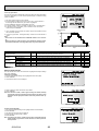
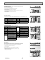
<Table 3.1>
—
16 A
9A
2 kW
• Joint pipe (15.88 → 12.7)
—
32 A
23 A
3 kW+
6 kW
• Remote sensor
—
3 kW
Capacity
—
26 A
Current
3 kW+
6 kW
~/N, 230 V, 50 Hz
2 kW+
4 kW
Capacity
• Wireless Receiver
1.0 MPa
(10 bar)
115 kg
1.0 MPa
(10 bar)
1 bar
12 L
—
328 kg
115 kg
1.0 MPa
(10 bar)
—
328 kg
114 kg
—
—
—
—
—
1.0 MPa
(10 bar)
—
327 kg
114 kg
—
1.0 MPa
(10 bar)
—
327 kg
—
16 A
13 A
3 kW+
6 kW
—
—
—
—
—
32 A
26 A
2 kW+
4 kW
32 A
26 A
2 kW+
4 kW
—
16 A
9A
2 kW
16 A
13 A
3 kW+
6 kW
—
—
—
32 A
23 A
3 kW+
6 kW
*3 Do not fit immersion heaters without thermal cut-out.
*2 Tested under BS7206 conditions .
16 A
13 A
3 kW
~/N, 230 V, 50 Hz
32 A
26 A
2 kW+
4 kW
*1 The environment must be frost-free.
—
16 A
13 A
3 kW+
6 kW
—
32 A
26 A
2 kW+
4 kW
—
—
—
—
—
16 A
13 A
3 kW+
6 kW
~/N, 230 V, 3~, 400 V, 3~, 230 V, ~/N, 230 V, ~/N, 230 V, 3~, 400 V, ~/N, 230 V, 3~, 400 V, ~/N, 230 V, ~/N, 230 V, ~/N, 230 V, 3~, 400 V, 3~, 230 V, ~/N, 230 V, 3~, 400 V,
50 Hz
50 Hz
50 Hz
50 Hz
50 Hz
50 Hz
50 Hz
50 Hz
50 Hz
50 Hz
50 Hz
50 Hz
50 Hz
50 Hz
50 Hz
10 A
Power supply
(Phase, voltage, frequency)
Immersion heater Power supply
(Phase, voltage, frequency)
*3
Booster heater
Breaker (*when powered
from independent source)
16 mins
~/N, 230 V, 50 Hz
Power supply
(Phase, voltage, frequency)
Time to reheat 70% of DHW tank to 65°C
—
21.75 mins
Time to raise DHW tank temp 15 - 65°C
See outdoor unit spec table.
Cooling
Cooling
Heating
—
Heating
9.52 mm
Outdoor
temperature
—
10 - 30°C
Cooling
25 - 60°C
9.52 mm
Heating
9.52 mm
Gas
9.52 mm
9.52 mm
15.88 mm 15.88 mm 15.88 mm 15.88 mm 15.88 mm 15.88 mm 15.88 mm 15.88 mm 15.88 mm
Liquid
0 - 35°C ( 80 %RH)
Control board
90°C/
0.7 MPa
(7 bar)
—
—
115 kg
328 kg
113 kg
326 kg
28 mm compression primary circuit/ 22 mm compression DHW circuit/22 mm compression solar thermal (Ancillary heating) circuit
Grundfos UPM2 25 70 - 180
1.0 MPa
(10 bar)
40 - 70°C
Ambient *1
Room temperature
Flow temperature
Refrigerant
(R410A)
Water
Temperature and pressure relief valve
1.0 MPa
(10 bar)
Thermal Cut-out (for dry run prevention)
Control thermistor
90°C
121°C
Manual reset thermostat
0.3 MPa (3 bar)
—
—
337 kg
122 kg
Min flow 5.5 l/min
1.0 MPa
(10 bar)
342 kg
127 kg
Flow switch
1.0 MPa
(10 bar)
342 kg
127 kg
Pressure relief valve
Control thermistor
1 bar
340 kg
125 kg
Charge pressure
343 kg
128 kg
12 L
1.0 MPa
(10 bar)
343 kg
128 kg
Nominal volume
• Wireless Remote Controller
Optional extras
Solar (ancillary) connection
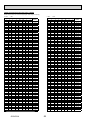
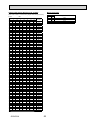
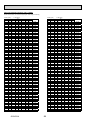
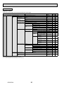
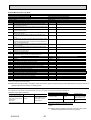
Electrical data
DHW tank performance *2
Guaranteed operating range
Target temperature range
Connections
Primary circuit circulating Pump
Safety device
Unvented expansion vessel
(Primary heating)
1.0 MPa
(10 bar)
343 kg
Plate heat exchanger
128 kg
Weight (full)
1600 x 595 x 680 mm (Height x Width x Depth)
200L
EHST20C- EHST20C- EHST20C- EHST20C- EHST20C- EHST20C- EHST20C- EHST20C- EHST20C- EHPT20X- EHPT20X- EHPT20X- EHPT20X- EHPT20X- EHPT20XVM6HB
YM9HB
TM9HB
VM2B
VM6B
YM9B
VM6EB
YM9EB
VM6SB
VM2HB
VM6HB
YM9HB
TM9HB
VM6B
YM9B
Weight (empty)
Overall unit dimensions
Nominal domestic hot water volume
Model name
3
SPECIFICATIONS
4
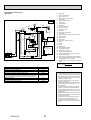
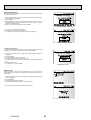
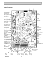
PART NAMES AND FUNCTIONS
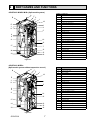
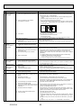
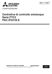
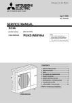
<EHST20C-*M*HB/*M*B> (Split model system)
Number
B
A
F
2
1
Automatic air vent
2
Pressure relief valve
3
Expansion vessel
4
Main controller
5
Control and electrical box
3
7
Immersion heater (Only for EHST20C-*M*HB)
4
8
DHW tank
9
3-way valve
5
10
Water circulation pump
1
19
E
J
K
8
9
11
10
12
17
7
13
15
14
18
Component
16
11
Manual air vent
12
Booster heater
13
Drain cock (Booster heater)
14
Strainer valve
15
Flow switch
16
Drain cock (Primary circuit)
17
Drain cock (DHW tank)
18
Plate heat exchanger
19
Manometer
A
DHW outlet
B
Cold water inlet
E
Inlet from space heating
F
Outlet to space heating
J
Refrigerant (Gas)
K
Refrigerant (Liquid)
Figure 4-1
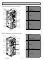
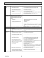
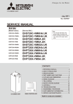
<EHST20C-*M*EB>
(Split model system without expansion vessel )
B
A
F
2
Automatic air vent
2
Pressure relief valve
4
Main controller
5
Control and electrical box
8
DHW tank
9
3-way valve
4
10
Water circulation pump
11
Manual air vent
5
12
Booster heater
13
Drain cock (Booster heater)
14
Strainer valve
15
Flow switch
16
Drain cock (Primary circuit)
17
Drain cock (DHW tank)
18
Plate heat exchanger
19
Manometer
1
8
9
11
10
12
17
13
15
14
18
16
Figure 4-2
OCH531A
Component
1
19
E
J
K
Number
7
A
DHW outlet
B
Cold water inlet
E
Inlet from space heating
F
Outlet to space heating
J
Refrigerant (Gas)
K
Refrigerant (Liquid)
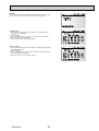
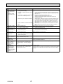
<EHST20C-VM6SB> (Solar split model system)
A
B
C
D
F
2
Number
1
19
E
J
K
3
Expansion vessel
4
Main controller
5
Control and electrical box
8
DHW tank
3-way valve
4
Water circulation pump
11
Manual air vent
5
12
Booster heater
13
Drain cock (Booster heater)
14
Strainer valve
15
Flow switch
16
Drain cock (Primary circuit)
17
Drain cock (DHW tank)
18
Plate heat exchanger
12
17
13
15
18
Pressure relief valve
3
10
10
14
Automatic air vent
2
9
8
9
11
Component
1
16
19
Manometer
A
DHW outlet
B
Cold water inlet
C
Outlet to solar
D
Inlet from solar
E
Inlet from space heating
F
Outlet to space heating
J
Refrigerant (Gas)
K
Refrigerant (Liquid)
Figure 4-3
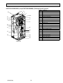
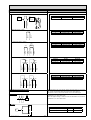
<EHPT20X-VM2HB> (UK Packaged model system)
Number
A
B
F
2
Automatic air vent
2
Pressure relief valve
3
Expansion vessel
4
Main controller
5
Control and electrical box
3
6
Temperature and pressure relief valve (not visible)
4
7
Immersion heater
8
DHW tank
9
3-way valve
10
Water circulation pump
11
Manual air vent
12
Booster heater
13
Drain cock (Booster heater)
14
Strainer valve
15
Flow switch
16
Drain cock (Primary circuit)
17
Drain cock (DHW tank)
19
Manometer
13
15
A
DHW outlet
B
Cold water inlet
E
Inlet from space heating
16
F
Outlet to space heating
1
19
E
G
H
5
6
8
9
11
10
12
17
7
14
Figure 4-4
OCH531A
Component
1
8
G
Inlet from heat pump
H
Outlet to heat pump
<EHPT20X-*M*HB/*M*B (except EHPT20X-VM2HB)> (Packaged model system)
A
B
Number
F
2
1
19
E
G
H
3
4
5
14
Pressure relief valve
3
Expansion vessel
4
Main controller
5
Control and electrical box
7
Immersion heater (Only for EHPT20X-*M*HB)
8
DHW tank
9
3-way valve
10
Water circulation pump
Manual air vent
Booster heater
13
Drain cock (Booster heater)
14
Strainer valve
15
Flow switch
12
16
Drain cock (Primary circuit)
17
Drain cock (DHW tank)
7
19
Manometer
A
DHW outlet
13
15
B
Cold water inlet
E
Inlet from space heating
F
Outlet to space heating
16
Figure 4-5
OCH531A
Automatic air vent
2
11
10
17
1
12
8
9
11
Component
9
G
Inlet from heat pump
H
Outlet to heat pump
5
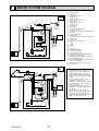
OUTLINES AND DIMENSIONS
<Unit: mm>
5-1. Technical Drawings
595
G1/2
Main controller
100±20
Air vent
Pressure relief valve
118
680
30
445
Temperature and
pressure relief valve
and its access plate
(EHPT20X-VM2HB)only)
1600
1
183
156
50
950
1095
Terminal block
Front panel
<Left side>
<Front>
C
D
E
47.1
0
550.2
541.1
522.8
492.2
470.8
Letter Pipe description
0
63.3
67.8
123
A
B
G/J
DHW outlet connection
22 mm/Compression
B
Cold water inlet connection
22 mm/Compression
C/D
Solar (ancillary heat source) connections 22 mm/Compression
E
Space heating return connection
28 mm/Compression
F
Space heating flow connection
28 mm/Compression
G
Flow from heat pump connection
(No plate heat exchanger)
28 mm/Compression
H
Return to heat pump connection
(No plate heat exchanger)
28 mm/Compression
J
Refrigerant (GAS)
(With plate heat exchanger)
15.88 mm/Flare
K
Refrigerant (LIQUID)
(With plate heat exchanger)
9.52 mm/Flare
H/K
L
Connection size/type
A
F
449.7
491.1
509.7
561.7
<Right side>
<Top>
L
Electrical cable inlets
—
For inlets and , run low-voltage wires including
external input wires and thermistor wires. For inlets ,
, and , run high-voltage wires including power cable,
indoor-outdoor cable, and external output wires.
*For a wireless receiver (option) cable, use inlet .
5-2. Service access diagrams
a
Service access
Parameter
a
b
c (distance behind unit not visible
in the right figure)
d
Dimension (mm)
300
150
b
b
10
500
Sufficient space MUST be left for the provision of discharge pipework as detailed
in National and Local Building Regulations.
The cylinder unit must be located indoors and in a frost-free environment, for
example in a utility room, to minimise heat loss from stored water.
d
Service access
OCH531A
10
6
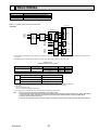
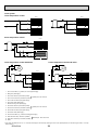
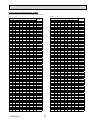
WIRING DIAGRAM
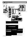
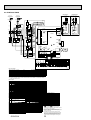
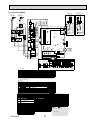
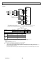
6-1. EHST20C-VM6HB
Cylinder unit powered
by independent source.
Cylinder unit powered
via outdoor unit
Power supply
to Booster heater
~/N 230V 50Hz
To outdoor
unit
D
RE
BLU
BLU
RED
M
1 3 5 A1 BHC2
1~
GRY
BHC1
1 3 5 A1
MP1
3
M
1~
1~
VLT
VLT
PNK
MP3
M
1
1~
3WV
BLU/No.3
BLU/No.4
WHT/No.1
WHT/No.2
BLU
A B
M
PNK
2 4 6 A2
2 4 6 A2
5
CNV1
(WHT)
Close
N
Open
M
1~
2
BHF
2
TBO.2
2
Signal
output
(Defrost)
Signal
output
(Error)
ORN
ORN
BHT
2
2
1
2
3
Signal
output
(Booster
heater2+)
2
2
2
X1
CNIH
(ORN)
1
2
3
4
5
6
7
8
9
10
11
12
13
14
1
3
X3
5
7
X4
9
11
X5A
13
1
X5B
5
X11
7
X12
3
6
CN3C
(BLU)
1
CNV1
(WHT)
5
8
10
CN3C 1
(BLU) 3
FTC4
12
6
CN105
(RED)
1
CNPWM
(WHT)
3
CNRF
(WHT)
1
5
1
5
LED2
3
7
1
CNBC
(GRY)
3
1
1
CNIH
(ORN)
CN108
CN22
(BLU)
CNBHT 1
(BLK) 2
SW4
CN2F CN20 CN21 CNW12 CNW5
(YLW) (RED) (YLW) (RED) (WHT)
1
1
1
1
1
2
3
2
3
4
2 4 6 8 10 12 14
5
1
7
LED1
SW2
1
2 4 6 8 10 12 14
6
SW1
8 1
8
SW3
1 3 5 7 9 11 13
3 5 7 9 11 13
TBI.1
1
1
TBI.2
1
8
3
CNBC
(GRY)
TBI.2
TBI.1
CN22
(BLU)
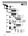
Item
Room thermostat 1 input
Flow switch 1 input
Flow switch 2 input (Zone1)
Demand control input
Outdoor thermostat input *1
Room thermostat 2 input
Flow switch 3 input (Zone2)
t°
t°
THW9
THW6
t°
THW7
t°
THWB2
t°
THW8
IN7
IN6
IN5
IN4
IN3
t°
THWB1
t°
2
Main
controller
1
Table 1 Signal Inputs
Terminal block Connector
TBI.1 1-2
—
TBI.1 3-4
CN2F
TBI.1 5-6
—
TBI.1 7-8
—
TBI.1 9-10
—
TBI.1 11-12
—
—
TBI.1 13-14
1 2 3 4 5 6 7 8 9 10 11 12 13 14
3
IN2
t°
1
IN1
t°
THW5
t°
CNW5
(WHT)
CNW12
(RED)
t°
6 7 8 9 10 11 12 13 14
CN2F
(YLW)
2
4 1
THW2
CN21
(YLW)
3 1
TH2
2 1
TH1
1
THW1
CN20
(RED)
1 2 3 4 5
Name
IN1
IN2
IN3
IN4
IN5
IN6
IN7
OFF (Open)
ON (Short)
Refer to SW2-1 in <6-16 Dip switch setting>
Refer to SW2-2 in <6-16 Dip switch setting>
Refer to SW3-2 in <6-16 Dip switch setting>
Normal
Heat source OFF/Boiler operation *2
Standard operation
Heater operation/Boiler operation *2
Refer to SW3-1 in <6-16 Dip switch setting>
Refer to SW3-3 in <6-16 Dip switch setting>
*1. If using outdoor thermostat for controlling operation of heaters, the lifetime of the heaters and
related parts may be reduced.
*2. To turn on the boiler operation, use the main controller to select “Boiler” in “External/input setting“
screen in the service menu.
Table 2 Outputs
Name
OUT1
OUT2
OUT3
OUT4
OUT5
OUT6
OUT7
OUT8
OUT9
OUT10
OUT11
OUT12
Terminal block Connector
Item
TBO.1 3-4
CNP1
Water circulation pump 1 output (Space heating & DHW)
TBO.1 5-6
—
Water circulation pump 2 output (Space heating for Zone1)
TBO.1 7-8
—
Water circulation pump 3 output (Space heating for Zone2)
TBO.1 9-11
CNV1
3-way valve output
TBO.1 12-13
—
Mixing valve output
TBO.1 13-14
—
CNBH 1-3 Booster heater 1 output
—
CNBH 5-7 Booster heater 2 output
TBO.2 11-12
—
Booster heater 2+ output
TBO.2 9-10
CNIH
Immersion heater output
TBO.1 1-2
—
Boiler output
TBO.2 1-2
—
Error output
TBO.2 3-4
—
Defrost output
Symbol
TB1
ECB1
ECB2
MP1
MP2
Name
Terminal block <Power supply, Outdoor unit>
Earth leakage circuit breaker for booster heater
Earth leakage circuit breaker for immersion heater
Water circulation pump1(Space heating & DHW)
Water circulation pump2
(Space heating for Zone1)(Field supply)
MP3
Water circulation pump3
(Space heating for Zone2)(Field supply)
3WV
MXV
BHT
BHF
BH1
BH2
BHC1
BHC2
BHCP
IHT
IH
IHC
3-way valve
Mixing valve (Field supply)
Thermostat for booster heater
Thermal fuse for booster heater
Booster heater 1
Booster heater 2
Contactor for booster heater 1
Contactor for booster heater 2
Contactor for booster heater protection
Thermostat (fixed temp.) for immersion heater
Immersion heater
Contactor for immersion heater
OCH531A
YLW
ORN
GRN/YLW
YLW
ORN
LED3
4
LED4
X7
3
Symbol
TH1
TH2
THW1
THW2
THW5
THW6
THW7
THW8
THW9
THWB1
THWB2
IN1
IN2
IN3
IN4
IN5
IN6
IN7
BRN
ORN
Figure 1
CNBH
(WHT)
X6
CN3C
(BLU)
1
BRN
ORN
3
TBO.2
2
1
1
CN01
(BLK)
5
3
1
14
X9
X8
3
3
1
2 TBO.1
1
4
8
9
10
11
12
13
14
CNBHT(BLK)
CNBH
(WHT)
S1 S2 S3 TB1
BLK
CN01
(BLK)
5
3
1
CN01 5
(BLK)
3
1
CNP1(WHT)
X2
1
3
2
BLK
L N
X10
3
MXV
BH1 BH2
IHT
IH
1
2
3
4
5
6
7
8
9
10
11
12
13
14
S1 S2 S3 TB1
YLW
ORN
TBO.1
CNP1
(WHT)
1
MP2
2 4 6 A2
RED
BLU
CNPWM
(WHT)
1
3
GRY
IHC 1 3 5 A1
1
Wireless receiver
(Option)
BLU
RED
3
2 4 6 A2
L N
3
F2
1 3 5 A1
BHCP
CN01
(BLK)
5
F1
Signal
output
(Boiler)
GRN/YLW
2 4
RED
BLU
2 4
YLW
ORN
ECB1
CIRCUIT
BREAKER
L N
(1) (3)
L N
(1) (3)
ECB2
RED
Power supply To outdoor
unit
~/N 230V 50Hz
RED
BLU
Power supply
to Immersion heater
~/N 230V 50Hz
OFF
OFF
OFF
OFF
Heating
Stop
Stop
OFF
OFF
OFF
OFF
OFF
Normal
Normal
Name
Thermistor (Room temp.)(Option)
Thermistor (Ref. liquid temp.)
Thermistor (Flow water temp.)
Thermistor (Return water temp.)
Thermistor (DHW tank water temp.)
Thermistor (Zone1 flow temp.)(Option)
Thermistor (Zone1 return temp.)(Option)
Thermistor (Zone2 flow temp.)(Option)
Thermistor (Zone2 return temp.)(Option)
Thermistor (Boiler flow temp.)(Option)
Thermistor (Boiler return temp.)(Option)
Room thermostat 1 (Field supply)
Flow switch 1
Flow switch 2 (Field supply)
Demand control (Field supply)
Outdoor thermostat (Field supply)
Room thermostat 2 (Field supply)
Flow switch 3 (Field supply)
11
ON
ON
ON
ON
DHW
Close
Open
ON
ON
ON
ON
ON
Error
Defrost
FLOW TEMP. CONTROLLER (FTC4)
TBO.1~2 Terminal block <Outputs>
TBI.1~2 Terminal block <Signal Inputs, Thermistor>
F1~F2 Fuse (T6.3AL250V)
SW1~4 Dip switch *See <6-16 Dip switch setting>.
X1~X12 Relay
LED1 Power supply (FTC4)
LED2 Power supply (Main controller)
LED3 Communication (FTC4-Outdoor unit)
LED4 Reading or writing data to SD card
CNPWM Pump speed control signal for MP1
CN108 SD card connector
1. Symbols used in wiring diagram are,
: connector,
: terminal block.
2. Indoor unit and outdoor unit connecting wires
have polarities, make sure to match terminal numbers
(S1, S2, S3) for correct wirings,
3. Since the outdoor unit side electric wiring may change,
be sure to check the outdoor unit electric wiring
diagram for servicing.
4. This diagram shows the wiring of indoor unit and
outdoor unit connecting wires (specification of 230V),
adopting superimposed system of power and signal.
When work to supply power separately to indoor
unit and outdoor unit was applied, refer to Figure 1.
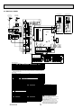
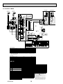
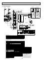
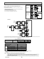
6-2. EHST20C-YM9HB
Cylinder unit powered
by independent source.
Cylinder unit powered
via outdoor unit
Power supply
to Booster heater
3~ 400V 50Hz
BLK
3
RED
WHT
BLK
M
1 3 5 A1 BHC2
1~
GRY
1 3 5 A1
GRY
BHC1
IHC 1 3 5 A1
MP1
3
M
1~
PNK
MP3
VLT
VLT
M
1
1~
3WV
BLU/No.4
BLU/No.5
BLU/No.6
WHT/No.1
WHT/No.2
WHT/No.3
BLU
A B
1~
PNK
2 4 6 A2
2 4 6 A2
M
5
CNV1
(WHT)
Close
N
Open
M
1~
2
BH1
BHF
2
ORN
ORN
Signal
output
(Defrost)
Signal
output
(Error)
2
2
1
2
3
Signal
output
(Booster
heater2+)
2
CNIH
(ORN)
2
2
1
5
6
7
X4
X5A
7
9
X12
11
13
3
6
CN105
(RED)
8
10
12
1
14
3
CNPWM
(WHT)
CNRF
(WHT)
1
5
LED4
CNBH
(WHT)
3
7
1
CNBC
(GRY)
3
1
1
CNIH
(ORN)
CN108
CN22
(BLU)
CNBHT 1
(BLK) 2
SW4
CN2F CN20 CN21 CNW12 CNW5
(YLW) (RED) (YLW) (RED) (WHT)
1
1
1
1
1
2
3
2
3
4
X6
X7
2 4 6 8 10 12 14
5
1
7
LED1
SW2
2 4 6 8 10 12 14
1 3 5 7 9 11 13
3 5 7 9 11 13
TBI.1
1
1
1
6
SW1
8 1
8
SW3
TBI.2
1
8
3
CNBC
(GRY)
TBI.1
TBI.2
1
Table 1 Signal Inputs
Terminal block Connector
TBI.1 1-2
—
TBI.1 3-4
CN2F
TBI.1 5-6
—
TBI.1 7-8
—
TBI.1 9-10
—
TBI.1 11-12
—
TBI.1 13-14
—
Item
Room thermostat 1 input
Flow switch 1 input
Flow switch 2 input (Zone1)
Demand control input
Outdoor thermostat input *1
Room thermostat 2 input
Flow switch 3 input (Zone2)
OFF (Open)
ON (Short)
Refer to SW2-1 in <6-16 Dip switch setting>
Refer to SW2-2 in <6-16 Dip switch setting>
Refer to SW3-2 in <6-16 Dip switch setting>
Normal
Heat source OFF/Boiler operation *2
Standard operation
Heater operation/Boiler operation *2
Refer to SW3-1 in <6-16 Dip switch setting>
Refer to SW3-3 in <6-16 Dip switch setting>
*1. If using outdoor thermostat for controlling operation of heaters, the lifetime of the heaters and
related parts may be reduced.
*2. To turn on the boiler operation, use the main controller to select “Boiler” in “External/input setting“
screen in the service menu.
Table 2 Outputs
Name
OUT1
OUT2
OUT3
OUT4
OUT5
OUT6
OUT7
OUT8
OUT9
OUT10
OUT11
OUT12
Terminal block Connector
Item
TBO.1 3-4
CNP1
Water circulation pump 1 output (Space heating & DHW)
TBO.1 5-6
—
Water circulation pump 2 output (Space heating for Zone1)
TBO.1 7-8
—
Water circulation pump 3 output (Space heating for Zone2)
TBO.1 9-11
CNV1
3-way valve output
TBO.1 12-13
—
Mixing valve output
TBO.1 13-14
—
CNBH 1-3 Booster heater 1 output
—
CNBH 5-7 Booster heater 2 output
TBO.2 11-12
—
Booster heater 2+ output
TBO.2 9-10
CNIH
Immersion heater output
TBO.1 1-2
—
Boiler output
TBO.2 1-2
—
Error output
TBO.2 3-4
—
Defrost output
Symbol
TB1
ECB1
ECB2
MP1
MP2
Name
Terminal block <Power supply, Outdoor unit>
Earth leakage circuit breaker for booster heater
Earth leakage circuit breaker for immersion heater
Water circulation pump1(Space heating & DHW)
Water circulation pump2
(Space heating for Zone1)(Field supply)
MP3
Water circulation pump3
(Space heating for Zone2)(Field supply)
3WV
MXV
BHT
BHF
BH1
BH2
BHC1
BHC2
BHCP
IHT
IH
IHC
3-way valve
Mixing valve (Field supply)
Thermostat for booster heater
Thermal fuse for booster heater
Booster heater 1
Booster heater 2
Contactor for booster heater 1
Contactor for booster heater 2
Contactor for booster heater protection
Thermostat (fixed temp.) for immersion heater
Immersion heater
Contactor for immersion heater
OCH531A
Symbol
TH1
TH2
THW1
THW2
THW5
THW6
THW7
THW8
THW9
THWB1
THWB2
IN1
IN2
IN3
IN4
IN5
IN6
IN7
OFF
OFF
OFF
OFF
Heating
Stop
Stop
OFF
OFF
OFF
OFF
OFF
Normal
Normal
Name
Thermistor (Room temp.)(Option)
Thermistor (Ref. liquid temp.)
Thermistor (Flow water temp.)
Thermistor (Return water temp.)
Thermistor (DHW tank water temp.)
Thermistor (Zone1 flow temp.)(Option)
Thermistor (Zone1 return temp.)(Option)
Thermistor (Zone2 flow temp.)(Option)
Thermistor (Zone2 return temp.)(Option)
Thermistor (Boiler flow temp.)(Option)
Thermistor (Boiler return temp.)(Option)
Room thermostat 1 (Field supply)
Flow switch 1
Flow switch 2 (Field supply)
Demand control (Field supply)
Outdoor thermostat (Field supply)
Room thermostat 2 (Field supply)
Flow switch 3 (Field supply)
ON
ON
ON
ON
DHW
Close
Open
ON
ON
ON
ON
ON
Error
Defrost
FLOW TEMP. CONTROLLER (FTC4)
TBO.1~2 Terminal block <Outputs>
TBI.1~2 Terminal block <Signal Inputs, Thermistor>
F1~F2 Fuse (T6.3AL250V)
SW1~4 Dip switch *See <6-16 Dip switch setting>
X1~X12 Relay
LED1 Power supply (FTC4)
LED2 Power supply (Main controller)
LED3 Communication (FTC4-Outdoor unit)
LED4 Reading or writing data to SD card
CNPWM Pump speed control signal for MP1
CN108 SD card connector
12
1. Symbols used in wiring diagram are,
: connector,
: terminal block.
2. Indoor unit and outdoor unit connecting wires
have polarities, make sure to match terminal numbers
(S1, S2, S3) for correct wirings,
3. Since the outdoor unit side electric wiring may change,
be sure to check the outdoor unit electric wiring
diagram for servicing.
4. This diagram shows the wiring of indoor unit and
outdoor unit connecting wires (specification of 230V),
adopting superimposed system of power and signal.
When work to supply power separately to indoor
unit and outdoor unit was applied, refer to Figure 1.
t°
THW9
t°
THW7
t°
THW6
t°
THWB2
t°
THW8
IN7
IN6
IN5
IN4
t°
THWB1
t°
2
Main
controller
CNW5
(WHT)
CN22
(BLU)
IN3
t°
1 2 3 4 5 6 7 8 9 10 11 12 13 14
3
IN2
t°
THW5
t°
1
IN1
CNW12
(RED)
t°
6 7 8 9 10 11 12 13 14
CN2F
(YLW)
2
4 1
THW2
3 1
TH1
2 1
TH2
1
THW1
CN21
(YLW)
CN20
(RED)
1 2 3 4 5
Name
IN1
IN2
IN3
IN4
IN5
IN6
IN7
YLW
ORN
GRN/YLW
YLW
ORN
1
5
LED2
1
1
3
BRN
ORN
Figure 1
X9
X8
CN3C
(BLU)
1
BRN
ORN
LED3
4
3
3
FTC4
2
5
X11
CN3C 1
(BLU) 3
CN01
(BLK)
5
3
1
TBO.2
1
X5B
CN3C
(BLU)
1
CNV1
(WHT)
5
8
9
10
11
12
13
14
CNBHT(BLK)
CNBH
(WHT)
3
2 TBO.1
1
4
3
1
3
2
1
2
3
4
5
6
7
8
9
10
11
12
13
14
S1 S2 S3 TB1
BLK
CN01
(BLK)
5
3
1
CN01 5
(BLK)
3
1
CNP1(WHT)
1
X3
TBO.2
2
BH2
BHT
X1
X2
3
MXV
IHT
IH
L N
X10
1
2
3
4
5
6
7
8
9
10
11
12
13
14
CNP1
(WHT)
1
MP2
2 4 6 A2
1
CNPWM
(WHT)
1
S1 S2 S3 TB1
YLW
ORN
BLU
RED
3
2 4 6 A2
D
RE T
WH LK
B
L N
3
F2
RED
BLU
RED
WHT
BLK
Signal
output
(Boiler)
1 3 5 A1
BHCP
CN01
(BLK)
5
F1
GRN/YLW
2 4 6
YLW
ORN
ECB1
2 4
CIRCUIT
BREAKER
L1 L2 L3
(1) (3) (5)
ECB2
RED
Power supply To outdoor
unit
~/N 230V 50Hz
Wireless receiver
(Option)
L N
(1) (3)
To outdoor
unit
RED
BLU
Power supply
to Immersion heater
~/N 230V 50Hz
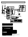
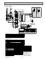
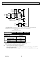
6-3. EHST20C-TM9HB
To outdoor
unit
5
CNV1
(WHT)
BLU/No.4
BLU/No.5
BLU/No.6
3WV
Close
N
Open
M
1~
MXV
IHT
2
IH
ORN
ORN
BH1
TBO.2
2
Signal
output
(Defrost)
BH2
BHF
2
2
Signal
output
(Error)
BHT
2
1
2
3
Signal
output
(Booster
heater2+)
2
2
2
6
7
X5A
X5B
1
X12
9
11
13
CIRCUIT
BREAKER
6
3
CN105
(RED)
8
10
12
1
14
3
CNPWM
(WHT)
CNRF
(WHT)
1
5
LED4
3
7
3
1
CNBC
(GRY)
3
1
1
CNIH
(ORN)
X7
5
SW4
2 4 6 8 10 12 14
7
1
1
LED1
TBI.1
3
CNBC
(GRY)
1
SW2
1
2 4 6 8 10 12 14
1 3 5 7 9 11 13
3 5 7 9 11 13
6
1
8
TBI.2
CNW5
(WHT)
CNW12
(RED)
1
1 2 3 4 5 6 7 8 9 10 11 12 13 14
CN22
(BLU)
3
1
t°
IN7
IN6
IN5
IN4
IN3
IN2
t°
IN1
t°
THW5
TH2
t°
THW1
t°
6 7 8 9 10 11 12 13 14
CN2F
(YLW)
2
4 1
THW2
CN21
(YLW)
CN20
(RED)
t°
TH1
3 1
8
SW3
TBI.2
1 2 3 4 5
2 1
SW1
8 1
TBI.1
1
t°
t°
t°
t°
t°
Table 1 Signal Inputs
Name
IN1
IN2
IN3
IN4
IN5
IN6
IN7
Terminal block Connector
TBI.1 1-2
—
TBI.1 3-4
CN2F
TBI.1 5-6
—
TBI.1 7-8
—
TBI.1 9-10
—
TBI.1 11-12
—
TBI.1 13-14
—
Item
Room thermostat 1 input
Flow switch 1 input
Flow switch 2 input (Zone1)
Demand control input
Outdoor thermostat input *1
Room thermostat 2 input
Flow switch 3 input (Zone2)
OFF (Open)
ON (Short)
Refer to SW2-1 in <6-16 Dip switch setting>
Refer to SW2-2 in <6-16 Dip switch setting>
Refer to SW3-2 in <6-16 Dip switch setting>
Normal
Heat source OFF/Boiler operation *2
Standard operation
Heater operation/Boiler operation *2
Refer to SW3-1 in <6-16 Dip switch setting>
Refer to SW3-3 in <6-16 Dip switch setting>
*1. If using outdoor thermostat for controlling operation of heaters, the lifetime of the heaters and
related parts may be reduced.
*2. To turn on the boiler operation, use the main controller to select “Boiler” in “External/input setting“
screen in the service menu.
Table 2 Outputs
Name
OUT1
OUT2
OUT3
OUT4
OUT5
OUT6
OUT7
OUT8
OUT9
OUT10
OUT11
OUT12
Terminal block Connector
Item
TBO.1 3-4
CNP1
Water circulation pump 1 output (Space heating & DHW)
TBO.1 5-6
—
Water circulation pump 2 output (Space heating for Zone1)
TBO.1 7-8
—
Water circulation pump 3 output (Space heating for Zone2)
CNV1
TBO.1 9-11
3-way valve output
TBO.1 12-13
—
Mixing valve output
TBO.1 13-14
—
CNBH 1-3 Booster heater 1 output
—
CNBH 5-7 Booster heater 2 output
TBO.2 11-12
—
Booster heater 2+ output
CNIH
TBO.2 9-10
Immersion heater output
TBO.1 1-2
—
Boiler output
TBO.2 1-2
—
Error output
TBO.2 3-4
—
Defrost output
Symbol
TB1
ECB1
ECB2
MP1
MP2
Name
Terminal block <Power supply, Outdoor unit>
Earth leakage circuit breaker for booster heater
Earth leakage circuit breaker for immersion heater
Water circulation pump1(Space heating & DHW)
Water circulation pump2
(Space heating for Zone1)(Field supply)
MP3
Water circulation pump3
(Space heating for Zone2)(Field supply)
3WV
MXV
BHT
BHF
BH1
BH2
BHC1
BHC2
BHCP
IHT
IH
IHC
3-way valve
Mixing valve (Field supply)
Thermostat for booster heater
Thermal fuse for booster heater
Booster heater 1
Booster heater 2
Contactor for booster heater 1
Contactor for booster heater 2
Contactor for booster heater protection
Thermostat (fixed temp.) for immersion heater
Immersion heater
Contactor for immersion heater
OCH531A
Symbol
TH1
TH2
THW1
THW2
THW5
THW6
THW7
THW8
THW9
THWB1
THWB2
IN1
IN2
IN3
IN4
IN5
IN6
IN7
OFF
OFF
OFF
OFF
Heating
Stop
Stop
OFF
OFF
OFF
OFF
OFF
Normal
Normal
YLW
ORN
YLW
ORN
RED
BLU
GRN/YLW
CN108
CN22
(BLU)
CNBHT 1
(BLK) 2
CN2F CN20 CN21 CNW12 CNW5
(YLW) (RED) (YLW) (RED) (WHT)
1
1
1
1
1
2
3
2
3
4
X6
YLW
ORN
1
5
LED2
CNBH
(WHT)
1
3
LED3
4
1
CNBHT(BLK)
CNBH
(WHT)
ORN
3
BRN
ORN
Figure 1
X9
X8
CN3C
(BLU)
1
BRN
TBO.2
5
7
CN3C 1
(BLU) 3
FTC4
2
3
X11
CN3C
(BLU)
1
CNV1
(WHT)
5
8
9
10
11
12
13
14
1
3
2
CNIH
(ORN)
1
2
3
4
5
6
7
8
9
10
11
12
13
14
5
X4
ON
ON
ON
ON
DHW
Close
Open
ON
ON
ON
ON
ON
Error
Defrost
Name
Thermistor (Room temp.)(Option)
Thermistor (Ref. liquid temp.)
Thermistor (Flow water temp.)
Thermistor (Return water temp.)
Thermistor (DHW tank water temp.)
Thermistor (Zone1 flow temp.)(Option)
Thermistor (Zone1 return temp.)(Option)
Thermistor (Zone2 flow temp.)(Option)
Thermistor (Zone2 return temp.)(Option)
Thermistor (Boiler flow temp.)(Option)
Thermistor (Boiler return temp.)(Option)
Room thermostat 1 (Field supply)
Flow switch 1
Flow switch 2 (Field supply)
Demand control (Field supply)
Outdoor thermostat (Field supply)
Room thermostat 2 (Field supply)
Flow switch 3 (Field supply)
13
2
Main
controller
VLT
VLT
1
M
2 TBO.1
1
4
3
X3
S1 S2 S3 TB1
CN01
(BLK)
5
3
1
THW9
MP3
1~
WHT/No.1
WHT/No.2
WHT/No.3
BLU
A B
PNK
2 4 6 A2
2 4 6 A2
1~
PNK
2 4 6 A2
M
3
THW7
1~
MP2
1
1
L N
BLK
CN01
(BLK)
5
3
1
CN01 5
(BLK)
3
1
CNP1(WHT)
X2
S1 S2 S3 TB1
Wireless receiver
(Option)
3
M
X1
THW6
GRY
1~
MP1
BLK
X10
THWB2
M
1 3 5 A1 BHC2
1
2
3
4
5
6
7
8
9
10
11
12
13
14
CNP1
(WHT)
1
THW8
RED
WHT
BLK
1 3 5 A1
GRY
RED
BLU
3
BHC1
IHC 1 3 5 A1
1
CNPWM
(WHT)
1
3
2 4 6 A2
D
RE T
WH LK
B
L N
3
F2
RED
BLU
Signal
output
(Boiler)
1 3 5 A1
BHCP
CN01
(BLK)
5
F1
GRN/YLW
2 4 6
RED
WHT
BLK
2 4
YLW
ORN
ECB1
ECB2
RED
Power supply To outdoor
unit
~/N 230V 50Hz
L1 L2 L3
(1) (3) (5)
THWB1
L N
(1) (3)
Cylinder unit powered
by independent source.
Cylinder unit powered
via outdoor unit
Power supply
to Booster heater
3~ 230V 50Hz
Power supply
to Immersion heater
~/N 230V 50Hz
FLOW TEMP. CONTROLLER (FTC4)
TBO.1~2 Terminal block <Outputs>
TBI.1~2 Terminal block <Signal Inputs, Thermistor>
F1~F2 Fuse (T6.3AL250V)
SW1~4 Dip switch *See <6-16 Dip switch setting>
X1~X12 Relay
LED1 Power supply (FTC4)
LED2 Power supply (Main controller)
LED3 Communication (FTC4-Outdoor unit)
LED4 Reading or writing data to SD card
CNPWM Pump speed control signal for MP1
CN108 SD card connector
1. Symbols used in wiring diagram are,
: connector,
: terminal block.
2. Indoor unit and outdoor unit connecting wires
have polarities, make sure to match terminal numbers (S1, S2, S3) for correct wirings,
3. Since the outdoor unit side electric wiring may change, be sure to check the outdoor unit
electric wiring diagram for servicing.
4. This diagram shows the wiring of indoor unit and outdoor unit connecting wires
(specification of 230V), adopting superimposed system of power and signal.
When work to supply power separately to indoor unit and outdoor unit was applied, refer
to Figure 1.
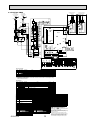
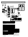
6-4. EHST20C-VM2B
To outdoor
unit
1~
2 4 6 A2
A B
1
M
1~
WHT/No.1
WHT/No.2
BLU
VLT
VLT
MP3
5
CNV1
(WHT)
3WV
Close
N
Open
M
1~
MXV
TBO.2
BH1
IHT
2
IH
BHF
2
Signal
output
(Defrost)
ORN
ORN
BHT
Signal
output
(Error)
2
2
1
2
3
Signal
output
(Booster
heater2+)
2
3
5
7
X4
X5A
1
X5B
3
5
X11
7
9
X12
11
13
CIRCUIT
BREAKER
CN3C
(BLU)
1
CNV1
(WHT)
5
CN3C 1
(BLU) 3
FTC4
3
6
CN105
(RED)
8
10
12
1
14
3
CNPWM
(WHT)
CNRF
(WHT)
1
5
LED4
3
7
1
1
CNBC
(GRY)
3
1
CNIH
(ORN)
CN108
CN22
(BLU)
CNBHT 1
(BLK) 2
SW4
CN2F CN20 CN21 CNW12 CNW5
(YLW) (RED) (YLW) (RED) (WHT)
1
1
1
1
1
2
3
2
3
4
X6
X7
2 4 6 8 10 12 14
7
LED1
1
SW2
1
2 4 6 8 10 12 14
6
TBI.1
TBI.2
1
8
TBI.2
CNW5
(WHT)
1 2 3 4 5 6 7 8 9 10 11 12 13 14
CN22
(BLU)
3
1
t°
IN7
IN6
IN5
IN4
IN3
IN1
t°
THW5
t°
1
IN2
CNW12
(RED)
t°
6 7 8 9 10 11 12 13 14
CN2F
(YLW)
2
4 1
THW1
t°
TH2
t°
TH1
3 1
THW2
CN21
(YLW)
CN20
(RED)
1 2 3 4 5
2 1
8
SW3
TBI.1
1
SW1
8 1
1 3 5 7 9 11 13
3 5 7 9 11 13
1
1
3
CNBC
(GRY)
t°
t°
t°
t°
Table 1 Signal Inputs
Terminal block Connector
TBI.1 1-2
—
TBI.1 3-4
CN2F
TBI.1 5-6
—
TBI.1 7-8
—
TBI.1 9-10
—
TBI.1 11-12
—
—
TBI.1 13-14
Item
Room thermostat 1 input
Flow switch 1 input
Flow switch 2 input (Zone1)
Demand control input
Outdoor thermostat input *1
Room thermostat 2 input
Flow switch 3 input (Zone2)
OFF (Open)
ON (Short)
Refer to SW2-1 in <6-16 Dip switch setting>
Refer to SW2-2 in <6-16 Dip switch setting>
Refer to SW3-2 in <6-16 Dip switch setting>
Normal
Heat source OFF/Boiler operation *2
Standard operation
Heater operation/Boiler operation *2
Refer to SW3-1 in <6-16 Dip switch setting>
Refer to SW3-3 in <6-16 Dip switch setting>
*1. If using outdoor thermostat for controlling operation of heaters, the lifetime of the heaters and
related parts may be reduced.
*2. To turn on the boiler operation, use the main controller to select “Boiler” in “External/input setting“
screen in the service menu.
Table 2 Outputs
Name
OUT1
OUT2
OUT3
OUT4
OUT5
OUT6
OUT7
OUT8
OUT9
OUT10
OUT11
OUT12
Terminal block Connector
Item
TBO.1 3-4
CNP1
Water circulation pump 1 output (Space heating & DHW)
TBO.1 5-6
—
Water circulation pump 2 output (Space heating for Zone1)
TBO.1 7-8
—
Water circulation pump 3 output (Space heating for Zone2)
CNV1
TBO.1 9-11
3-way valve output
TBO.1 12-13
—
Mixing valve output
TBO.1 13-14
—
CNBH 1-3 Booster heater 1 output
—
CNBH 5-7 Booster heater 2 output
TBO.2 11-12
—
Booster heater 2+ output
CNIH
TBO.2 9-10
Immersion heater output
TBO.1 1-2
—
Boiler output
TBO.2 1-2
—
Error output
TBO.2 3-4
—
Defrost output
Symbol
TB1
ECB1
ECB2
MP1
MP2
Name
Terminal block <Power supply, Outdoor unit>
Earth leakage circuit breaker for booster heater
Earth leakage circuit breaker for immersion heater (Option)
Water circulation pump1(Space heating & DHW)
Water circulation pump2
(Space heating for Zone1)(Field supply)
MP3
Water circulation pump3
(Space heating for Zone2)(Field supply)
3WV
MXV
BHT
BHF
BH1
BHC1
BHCP
IHT
IH
IHC
3-way valve
Mixing valve (Field supply)
Thermostat for booster heater
Thermal fuse for booster heater
Booster heater 1
Contactor for booster heater 1
Contactor for booster heater protection
Thermostat (fixed temp.) for immersion heater (Option)
Immersion heater (Option)
Contactor for immersion heater (Option)
OCH531A
Symbol
TH1
TH2
THW1
THW2
THW5
THW6
THW7
THW8
THW9
THWB1
THWB2
IN1
IN2
IN3
IN4
IN5
IN6
IN7
OFF
OFF
OFF
OFF
Heating
Stop
Stop
OFF
OFF
OFF
OFF
OFF
Normal
Normal
Name
Thermistor (Room temp.)(Option)
Thermistor (Ref. liquid temp.)
Thermistor (Flow water temp.)
Thermistor (Return water temp.)
Thermistor (DHW tank water temp.)
Thermistor (Zone1 flow temp.)(Option)
Thermistor (Zone1 return temp.)(Option)
Thermistor (Zone2 flow temp.)(Option)
Thermistor (Zone2 return temp.)(Option)
Thermistor (Boiler flow temp.)(Option)
Thermistor (Boiler return temp.)(Option)
Room thermostat 1 (Field supply)
Flow switch 1
Flow switch 2 (Field supply)
Demand control (Field supply)
Outdoor thermostat (Field supply)
Room thermostat 2 (Field supply)
Flow switch 3 (Field supply)
YLW
ORN
YLW
ORN
RED
BLU
GRN/YLW
1
5
LED2
CNBH
(WHT)
5
Name
IN1
IN2
IN3
IN4
IN5
IN6
IN7
YLW
ORN
LED3
4
1
1
3
BRN
ORN
Figure 1
X9
X8
CN3C
(BLU)
1
BRN
ORN
TBO.2
2
3
3
2
6
8
9
10
11
12
13
14
CNBHT(BLK)
CNBH
(WHT)
3
2 TBO.1
1
4
1
3
2
CNIH
(ORN)
1
2
3
4
5
6
7
8
9
10
11
12
13
14
1
X3
1
ON
ON
ON
ON
DHW
Close
Open
ON
ON
ON
ON
ON
Error
Defrost
FLOW TEMP. CONTROLLER (FTC4)
TBO.1~2 Terminal block <Outputs>
TBI.1~2 Terminal block <Signal Inputs, Thermistor>
F1~F2 Fuse (T6.3AL250V)
SW1~4 Dip switch *See <6-16 Dip switch setting>
X1~X12 Relay
LED1 Power supply (FTC4)
LED2 Power supply (Main controller)
LED3 Communication (FTC4-Outdoor unit)
LED4 Reading or writing data to SD card
CNPWM Pump speed control signal for MP1
CN108 SD card connector
1. Symbols used in wiring diagram are,
: connector,
: terminal block.
2. Indoor unit and outdoor unit connecting wires
have polarities, make sure to match terminal numbers (S1, S2, S3) for correct wirings,
3. Since the outdoor unit side electric wiring may change, be sure to check the outdoor unit
electric wiring diagram for servicing.
4. This diagram shows the wiring of indoor unit and outdoor unit connecting wires
(specification of 230V), adopting superimposed system of power and signal.
When work to supply power separately to indoor unit and outdoor unit was applied, refer
to Figure 1.
14
t°
2
Main
controller
2 4 6 A2
CN01 5
(BLK)
3
1
CNP1(WHT)
S1 S2 S3 TB1
CN01
(BLK)
5
3
1
THW9
1~
M
X1
X2
THW7
M
MP2
L N
BLK
CN01
(BLK)
5
3
1
Wireless receiver
(Option)
3
BLK
S1 S2 S3 TB1
X10
THW6
GRY
GRY
1~
MP1
1
2
3
4
5
6
7
8
9
10
11
12
13
14
THWB2
CNP1
(WHT)
1
M
1 3 5 A1
1
THW8
TBO.1
3
BHC1
IHC 1 3 5 A1
F2
CNPWM
(WHT)
1
THWB1
BLU
3
2 4 6 A2
D
RE
BLU
L N
3
RED
BLU
Signal
output
(Boiler)
1 3 5 A1
BHCP
CN01
(BLK)
5
F1
GRN/YLW
2 4
RED
BLU
2 4
YLW
ORN
ECB1
ECB2
RED
Power supply To outdoor
unit
~/N 230V 50Hz
L N
(1) (3)
L N
(1) (3)
RED
Cylinder unit powered
by independent source.
Cylinder unit powered
via outdoor unit
Power supply
to Booster heater
~/N 230V 50Hz
Power supply
to Immersion heater
~/N 230V 50Hz
6-5. EHST20C-VM6B
To outdoor
unit
BLU
RED
M
1 3 5 A1 BHC2
1~
GRY
GRY
1 3 5 A1
MP1
CNP1
(WHT)
1
3
M
1~
MP2
1~
MP3
VLT
VLT
M
1
1~
3WV
BLU/No.3
BLU/No.4
WHT/No.1
WHT/No.2
BLU
A B
M
PNK
2 4 6 A2
2 4 6 A2
PNK
2 4 6 A2
5
CNV1
(WHT)
Close
N
Open
M
1~
2
IH
BHF
2
Signal
output
(Defrost)
Signal
output
(Error)
ORN
ORN
2
2
1
2
3
Signal
output
(Booster
heater2+)
2
2
2
X1
CNIH
(ORN)
1
2
3
4
5
6
7
8
9
10
11
12
13
14
3
X3
5
7
X4
9
11
X5A
13
1
X5B
5
X11
7
9
X12
11
13
CIRCUIT
BREAKER
1
6
CN3C 1
(BLU) 3
FTC4
12
3
2
LED3
4
6
CN105
(RED)
8
10
12
1
14
3
CNPWM
(WHT)
CNRF
(WHT)
1
5
1
5
LED2
3
7
1
CNBC
(GRY)
1
3
1
CNIH
(ORN)
CN108
CN22
(BLU)
CNBHT 1
(BLK) 2
SW4
CN2F CN20 CN21 CNW12 CNW5
(YLW) (RED) (YLW) (RED) (WHT)
1
1
1
1
1
2
3
2
3
4
X7
2 4 6 8 10 12 14
5
1
7
LED1
1
SW2
1
2 4 6 8 10 12 14
1 3 5 7 9 11 13
3 5 7 9 11 13
TBI.1
1
6
SW1
8 1
8
SW3
TBI.2
1
8
TBI.1
TBI.2
1 2 3 4 5 6 7 8 9 10 11 12 13 14
CN22
(BLU)
3
Table 1 Signal Inputs
Terminal block Connector
TBI.1 1-2
—
TBI.1 3-4
CN2F
TBI.1 5-6
—
TBI.1 7-8
—
TBI.1 9-10
—
TBI.1 11-12
—
TBI.1 13-14
—
Item
Room thermostat 1 input
Flow switch 1 input
Flow switch 2 input (Zone1)
Demand control input
Outdoor thermostat input *1
Room thermostat 2 input
Flow switch 3 input (Zone2)
OFF (Open)
ON (Short)
Refer to SW2-1 in <6-16 Dip switch setting>
Refer to SW2-2 in <6-16 Dip switch setting>
Refer to SW3-2 in <6-16 Dip switch setting>
Normal
Heat source OFF/Boiler operation *2
Standard operation
Heater operation/Boiler operation *2
Refer to SW3-1 in <6-16 Dip switch setting>
Refer to SW3-3 in <6-16 Dip switch setting>
*1. If using outdoor thermostat for controlling operation of heaters, the lifetime of the heaters and
related parts may be reduced.
*2. To turn on the boiler operation, use the main controller to select “Boiler” in “External/input setting“
screen in the service menu.
Table 2 Outputs
Name
OUT1
OUT2
OUT3
OUT4
OUT5
OUT6
OUT7
OUT8
OUT9
OUT10
OUT11
OUT12
Symbol
TB1
ECB1
ECB2
MP1
MP2
MP3
3WV
MXV
BHT
BHF
BH1
BH2
BHC1
BHC2
BHCP
IHT
IH
IHC
Terminal block Connector
Item
TBO.1 3-4
CNP1
Water circulation pump 1 output (Space heating & DHW)
TBO.1 5-6
—
Water circulation pump 2 output (Space heating for Zone1)
TBO.1 7-8
—
Water circulation pump 3 output (Space heating for Zone2)
TBO.1 9-11
CNV1
3-way valve output
TBO.1 12-13
—
Mixing valve output
TBO.1 13-14
—
CNBH 1-3 Booster heater 1 output
—
CNBH 5-7 Booster heater 2 output
TBO.2 11-12
—
Booster heater 2+ output
TBO.2 9-10
CNIH
Immersion heater output
TBO.1 1-2
—
Boiler output
TBO.2 1-2
—
Error output
TBO.2 3-4
—
Defrost output
Name
Terminal block <Power supply, Outdoor unit>
Earth leakage circuit breaker for booster heater
Earth leakage circuit breaker for immersion heater (Option)
Water circulation pump1(Space heating & DHW)
Water circulation pump2
(Space heating for Zone1)(Field supply)
Symbol
TH1
TH2
THW1
THW2
THW5
THW6
Water circulation pump3
THW7
(Space heating for Zone2)(Field supply)
THW8
3-way valve
THW9
THWB1
Mixing valve (Field supply)
Thermostat for booster heater
THWB2
Thermal fuse for booster heater
IN1
Booster heater 1
IN2
Booster heater 2
IN3
Contactor for booster heater 1
IN4
Contactor for booster heater 2
IN5
Contactor for booster heater protection
IN6
Thermostat (fixed temp.) for immersion heater (Option) IN7
Immersion heater (Option)
Contactor for immersion heater (Option)
OCH531A
Name
Thermistor (Room temp.)(Option)
Thermistor (Ref. liquid temp.)
Thermistor (Flow water temp.)
Thermistor (Return water temp.)
Thermistor (DHW tank water temp.)
Thermistor (Zone1 flow temp.)(Option)
Thermistor (Zone1 return temp.)(Option)
Thermistor (Zone2 flow temp.)(Option)
Thermistor (Zone2 return temp.)(Option)
Thermistor (Boiler flow temp.)(Option)
Thermistor (Boiler return temp.)(Option)
Room thermostat 1 (Field supply)
Flow switch 1
Flow switch 2 (Field supply)
Demand control (Field supply)
Outdoor thermostat (Field supply)
Room thermostat 2 (Field supply)
Flow switch 3 (Field supply)
15
OFF
OFF
OFF
OFF
Heating
Stop
Stop
OFF
OFF
OFF
OFF
OFF
Normal
Normal
ON
ON
ON
ON
DHW
Close
Open
ON
ON
ON
ON
ON
Error
Defrost
FLOW TEMP. CONTROLLER (FTC4)
TBO.1~2 Terminal block <Outputs>
TBI.1~2 Terminal block <Signal Inputs, Thermistor>
F1~F2 Fuse (T6.3AL250V)
SW1~4 Dip switch *See <6-16 Dip switch setting>
X1~X12 Relay
LED1 Power supply (FTC4)
LED2 Power supply (Main controller)
LED3 Communication (FTC4-Outdoor unit)
LED4 Reading or writing data to SD card
CNPWM Pump speed control signal for MP1
CN108 SD card connector
1. Symbols used in wiring diagram are,
: connector,
: terminal block.
2. Indoor unit and outdoor unit connecting wires
have polarities, make sure to match terminal numbers
(S1, S2, S3) for correct wirings,
3. Since the outdoor unit side electric wiring may change,
be sure to check the outdoor unit electric wiring
diagram for servicing.
4. This diagram shows the wiring of indoor unit and
outdoor unit connecting wires (specification of 230V),
adopting superimposed system of power and signal.
When work to supply power separately to indoor
unit and outdoor unit was applied, refer to Figure 1.
t°
THW9
t°
THW7
t°
THW6
t°
THWB2
THW8
t°
THWB1
IN7
IN6
IN5
IN4
IN3
IN2
t°
2
Main
controller
1
t°
IN1
t°
1
THW5
t°
CNW5
(WHT)
CNW12
(RED)
t°
6 7 8 9 10 11 12 13 14
CN2F
(YLW)
2
4 1
THW2
t°
TH2
3 1
TH1
2 1
THW1
CN21
(YLW)
CN20
(RED)
1 2 3 4 5
1
YLW
ORN
BRN
ORN
Figure 1
LED4
X6
3
TBO.2
CNBH
(WHT)
1
CN3C
(BLU)
1
BRN
ORN
14
1
X8
CN01
(BLK)
5
3
1
3
CNBC
(GRY)
Name
IN1
IN2
IN3
IN4
IN5
IN6
IN7
RED
BLU
GRN/YLW
YLW
ORN
RED
BLU
CN3C
(BLU)
1
CNV1
(WHT)
5
8
10
3
3
3
2 TBO.1
1
4
X9
CNBHT(BLK)
CNBH
(WHT)
BLK
CN01
(BLK)
5
3
1
CN01 5
(BLK)
3
1
CNP1(WHT)
1
1
3
2
BLK
X10
X2
TBO.2
2
BHT
1
2
3
4
5
6
7
8
9
10
11
12
13
14
3
MXV
BH1 BH2
IHT
1
S1 S2 S3 TB1
L N
YLW
ORN
TBO.1
3
BHC1
IHC 1 3 5 A1
F2
CNPWM
(WHT)
1
S1 S2 S3 TB1
Wireless receiver
(Option)
BLU
RED
3
2 4 6 A2
D
RE
BLU
L N
3
1 3 5 A1
BHCP
CN01
(BLK)
5
F1
Signal
output
(Boiler)
GRN/YLW
2 4
RED
BLU
2 4
YLW
ORN
ECB1
ECB2
RED
Power supply To outdoor
unit
~/N 230V 50Hz
L N
(1) (3)
L N
(1) (3)
Cylinder unit powered
by independent source.
Cylinder unit powered
via outdoor unit
Power supply
to Booster heater
~/N 230V 50Hz
Power supply
to Immersion heater
~/N 230V 50Hz
6-6. EHST20C-YM9B
Cylinder unit powered
by independent source.
Cylinder unit powered
via outdoor unit
Power supply
to Booster heater
3~ 400V 50Hz
RED
WHT
BLK
M
1 3 5 A1 BHC2
1~
GRY
BHC1
1 3 5 A1
GRY
IHC 1 3 5 A1
MP1
CNP1
(WHT)
1
3
M
1~
MP2
PNK
1~
M
1
1~
3WV
BLU/No.4
BLU/No.5
BLU/No.6
WHT/No.1
WHT/No.2
WHT/No.3
BLU
A B
M
MP3
PNK
2 4 6 A2
2 4 6 A2
VLT
VLT
2 4 6 A2
5
CNV1
(WHT)
Close
N
Open
M
1~
2
IH
TBO.2
Signal
output
(Error)
2
BH2
BHT
Signal
output
(Defrost)
ORN
ORN
BH1
BHF
2
2
2
1
2
3
Signal
output
(Booster
heater2+)
2
CNIH
(ORN)
2
2
X1
1
3
X3
5
7
X4
9
11
X5A
13
1
X5B
5
X11
7
9
X12
11
13
4
1
3
6
5
CN3C
(BLU)
1
CNV1
(WHT)
8
10
CN3C 1
(BLU) 3
FTC4
12
3
6
CN105
(RED)
8
10
12
1
14
3
CNPWM
(WHT)
CNRF
(WHT)
1
5
1
5
LED2
3
1
CNBC
(GRY)
3
CNIH
(ORN)
1
1
CN108
CN22
(BLU)
CNBHT 1
(BLK) 2
SW4
CN2F CN20 CN21 CNW12 CNW5
(YLW) (RED) (YLW) (RED) (WHT)
1
1
1
1
1
2
3
2
3
4
1
7
3 5 7 9 11 13
TBI.1
1
1
SW2
1
2 4 6 8 10 12 14
1 3 5 7 9 11 13
2 4 6 8 10 12 14
5
LED1
6
SW1
8 1
8
SW3
TBI.2
1
8
3
CNBC
(GRY)
TBI.2
TBI.1
1 2 3 4 5 6 7 8 9 10 11 12 13 14
CN22
(BLU)
3
Table 1 Signal Inputs
Terminal block Connector
TBI.1 1-2
—
TBI.1 3-4
CN2F
TBI.1 5-6
—
TBI.1 7-8
—
TBI.1 9-10
—
TBI.1 11-12
—
TBI.1 13-14
—
Item
Room thermostat 1 input
Flow switch 1 input
Flow switch 2 input (Zone1)
Demand control input
Outdoor thermostat input *1
Room thermostat 2 input
Flow switch 3 input (Zone2)
OFF (Open)
ON (Short)
Refer to SW2-1 in <6-16 Dip switch setting>
Refer to SW2-2 in <6-16 Dip switch setting>
Refer to SW3-2 in <6-16 Dip switch setting>
Normal
Heat source OFF/Boiler operation *2
Standard operation
Heater operation/Boiler operation *2
Refer to SW3-1 in <6-16 Dip switch setting>
Refer to SW3-3 in <6-16 Dip switch setting>
*1. If using outdoor thermostat for controlling operation of heaters, the lifetime of the heaters and
related parts may be reduced.
*2. To turn on the boiler operation, use the main controller to select “Boiler” in “External/input setting“
screen in the service menu.
Table 2 Outputs
Name
OUT1
OUT2
OUT3
OUT4
Terminal block Connector
Item
TBO.1 3-4
CNP1
Water circulation pump 1 output (Space heating & DHW)
TBO.1 5-6
—
Water circulation pump 2 output (Space heating for Zone1)
TBO.1 7-8
—
Water circulation pump 3 output (Space heating for Zone2)
TBO.1 9-11
CNV1
3-way valve output
TBO.1 12-13
—
Mixing valve output
TBO.1 13-14
—
CNBH 1-3 Booster heater 1 output
—
CNBH 5-7 Booster heater 2 output
TBO.2 11-12
—
Booster heater 2+ output
TBO.2 9-10
CNIH
Immersion heater output
TBO.1 1-2
—
Boiler output
TBO.2 1-2
—
Error output
TBO.2 3-4
—
Defrost output
OUT5
OUT6
OUT7
OUT8
OUT9
OUT10
OUT11
OUT12
Symbol
TB1
ECB1
ECB2
MP1
MP2
MP3
3WV
MXV
BHT
BHF
BH1
BH2
BHC1
BHC2
BHCP
IHT
IH
IHC
Name
Terminal block <Power supply, Outdoor unit>
Earth leakage circuit breaker for booster heater
Earth leakage circuit breaker for immersion heater (Option)
Water circulation pump1(Space heating & DHW)
Water circulation pump2
(Space heating for Zone1)(Field supply)
Symbol
TH1
TH2
THW1
THW2
THW5
THW6
Water circulation pump3
THW7
(Space heating for Zone2)(Field supply)
THW8
3-way valve
THW9
THWB1
Mixing valve (Field supply)
Thermostat for booster heater
THWB2
Thermal fuse for booster heater
IN1
Booster heater 1
IN2
Booster heater 2
IN3
Contactor for booster heater 1
IN4
Contactor for booster heater 2
IN5
Contactor for booster heater protection
IN6
Thermostat (fixed temp.) for immersion heater (Option) IN7
Immersion heater (Option)
Contactor for immersion heater (Option)
OCH531A
OFF
OFF
OFF
OFF
Heating
Stop
Stop
OFF
OFF
OFF
OFF
OFF
Normal
Normal
Name
Thermistor (Room temp.)(Option)
Thermistor (Ref. liquid temp.)
Thermistor (Flow water temp.)
Thermistor (Return water temp.)
Thermistor (DHW tank water temp.)
Thermistor (Zone1 flow temp.)(Option)
Thermistor (Zone1 return temp.)(Option)
Thermistor (Zone2 flow temp.)(Option)
Thermistor (Zone2 return temp.)(Option)
Thermistor (Boiler flow temp.)(Option)
Thermistor (Boiler return temp.)(Option)
Room thermostat 1 (Field supply)
Flow switch 1
Flow switch 2 (Field supply)
Demand control (Field supply)
Outdoor thermostat (Field supply)
Room thermostat 2 (Field supply)
Flow switch 3 (Field supply)
ON
ON
ON
ON
DHW
Close
Open
ON
ON
ON
ON
ON
Error
Defrost
FLOW TEMP. CONTROLLER (FTC4)
TBO.1~2 Terminal block <Outputs>
TBI.1~2 Terminal block <Signal Inputs, Thermistor>
F1~F2 Fuse (T6.3AL250V)
SW1~4 Dip switch *See <6-16 Dip switch setting>
X1~X12 Relay
LED1 Power supply (FTC4)
LED2 Power supply (Main controller)
LED3 Communication (FTC4-Outdoor unit)
LED4 Reading or writing data to SD card
CNPWM Pump speed control signal for MP1
CN108 SD card connector
1. Symbols used in wiring diagram are,
: connector,
: terminal block.
2. Indoor unit and outdoor unit connecting wires
have polarities, make sure to match terminal numbers
(S1, S2, S3) for correct wirings,
3. Since the outdoor unit side electric wiring may change,
be sure to check the outdoor unit electric wiring
diagram for servicing.
4. This diagram shows the wiring of indoor unit and
outdoor unit connecting wires (specification of 230V),
adopting superimposed system of power and signal.
When work to supply power separately to indoor
unit and outdoor unit was applied, refer to Figure 1.
16
t°
THW9
t°
THW7
t°
THW6
t°
THWB2
THW8
t°
THWB1
IN7
IN6
IN5
IN4
IN3
t°
2
Main
controller
1
t°
IN2
t°
1
IN1
t°
THW5
t°
CNW5
(WHT)
CNW12
(RED)
t°
6 7 8 9 10 11 12 13 14
CN2F
(YLW)
2
4 1
THW1
3 1
TH2
2 1
TH1
1
THW2
CN21
(YLW)
CN20
(RED)
1 2 3 4 5
Name
IN1
IN2
IN3
IN4
IN5
IN6
IN7
YLW
ORN
GRN/YLW
YLW
ORN
LED3
4
7
X7
3
BRN
ORN
Figure 1
LED4
X6
CN3C
(BLU)
1
BRN
ORN
TBO.2
2
CNBH
(WHT)
1
CN01
(BLK)
5
3
1
14
1
3
3
1
2 TBO.1
X9
X8
CNBHT(BLK)
CNBH
(WHT)
S1 S2 S3 TB1
BLK
CN01
(BLK)
5
3
1
CN01 5
(BLK)
3
1
CNP1(WHT)
X2
1
3
2
1
2
3
4
5
6
7
8
9
10
11
12
13
14
L N
X10
3
MXV
IHT
BLK
1
2
3
4
5
6
7
8
9
10
11
12
13
14
S1 S2 S3 TB1
YLW
ORN
CNPWM
(WHT)
1
3
D
RE T
WH LK
B
1
RED
BLU
RED
WHT
BLK
BLU
RED
3
2 4 6 A2
L N
3
F2
1 3 5 A1
BHCP
CN01
(BLK)
5
F1
Signal
output
(Boiler)
GRN/YLW
2 4 6
YLW
ORN
ECB1
2 4
CIRCUIT
BREAKER
L1 L2 L3
(1) (3) (5)
ECB2
RED
Power supply To outdoor
unit
~/N 230V 50Hz
Wireless receiver
(Option)
L N
(1) (3)
To outdoor
unit
RED
BLU
Power supply
to Immersion heater
~/N 230V 50Hz
6-7. EHST20C-VM6EB
To outdoor
unit
BLU
RED
M
1 3 5 A1 BHC2
1~
GRY
GRY
1 3 5 A1
MP1
CNP1
(WHT)
1
3
M
1~
MP2
1~
MP3
VLT
VLT
M
1
1~
3WV
BLU/No.3
BLU/No.4
WHT/No.1
WHT/No.2
BLU
A B
M
PNK
2 4 6 A2
2 4 6 A2
PNK
2 4 6 A2
5
CNV1
(WHT)
Close
N
Open
M
1~
2
IH
BHF
2
Signal
output
(Defrost)
ORN
ORN
2
2
1
2
3
Signal
output
(Booster
heater2+)
2
CNIH
(ORN)
2
2
X1
3
X3
5
7
X4
9
1
2
3
4
5
6
7
8
9
10
11
12
13
14
11
X5A
13
X5B
1
5
X11
7
9
X12
11
13
CIRCUIT
BREAKER
1
3
2 TBO.1
1
4
6
CN3C 1
(BLU) 3
FTC4
12
3
6
CN105
(RED)
8
10
12
1
14
3
CNPWM
(WHT)
CNRF
(WHT)
1
5
1
5
LED2
3
3
1
CNBC
(GRY)
3
1
1
CNIH
(ORN)
CN108
CN22
(BLU)
CNBHT 1
(BLK) 2
SW4
CN2F CN20 CN21 CNW12 CNW5
(YLW) (RED) (YLW) (RED) (WHT)
1
1
1
1
1
2
3
2
3
4
X7
2 4 6 8 10 12 14
5
1
7
LED1
SW2
TBI.1
1
1
2 4 6 8 10 12 14
1 3 5 7 9 11 13
3 5 7 9 11 13
1
6
SW1
8 1
8
SW3
TBI.2
1
8
3
CNBC
(GRY)
TBI.2
TBI.1
1 2 3 4 5 6 7 8 9 10 11 12 13 14
CN22
(BLU)
3
Table 1 Signal Inputs
Terminal block Connector
TBI.1 1-2
—
TBI.1 3-4
CN2F
TBI.1 5-6
—
TBI.1 7-8
—
TBI.1 9-10
—
TBI.1 11-12
—
TBI.1 13-14
—
Item
Room thermostat 1 input
Flow switch 1 input
Flow switch 2 input (Zone1)
Demand control input
Outdoor thermostat input *1
Room thermostat 2 input
Flow switch 3 input (Zone2)
OFF (Open)
ON (Short)
Refer to SW2-1 in <6-16 Dip switch setting>
Refer to SW2-2 in <6-16 Dip switch setting>
Refer to SW3-2 in <6-16 Dip switch setting>
Normal
Heat source OFF/Boiler operation *2
Standard operation
Heater operation/Boiler operation *2
Refer to SW3-1 in <6-16 Dip switch setting>
Refer to SW3-3 in <6-16 Dip switch setting>
*1. If using outdoor thermostat for controlling operation of heaters, the lifetime of the heaters and
related parts may be reduced.
*2. To turn on the boiler operation, use the main controller to select “Boiler” in “External/input setting“
screen in the service menu.
Table 2 Outputs
Name
OUT1
OUT2
OUT3
OUT4
OUT5
OUT6
OUT7
OUT8
OUT9
OUT10
OUT11
OUT12
Symbol
TB1
ECB1
ECB2
MP1
MP2
MP3
3WV
MXV
BHT
BHF
BH1
BH2
BHC1
BHC2
BHCP
IHT
IH
IHC
OCH531A
Terminal block Connector
Item
TBO.1 3-4
CNP1
Water circulation pump 1 output (Space heating & DHW)
TBO.1 5-6
—
Water circulation pump 2 output (Space heating for Zone1)
TBO.1 7-8
—
Water circulation pump 3 output (Space heating for Zone2)
TBO.1 9-11
CNV1
3-way valve output
TBO.1 12-13
—
Mixing valve output
TBO.1 13-14
—
CNBH 1-3 Booster heater 1 output
—
CNBH 5-7 Booster heater 2 output
TBO.2 11-12
—
Booster heater 2+ output
TBO.2 9-10
CNIH
Immersion heater output
TBO.1 1-2
—
Boiler output
TBO.2 1-2
—
Error output
TBO.2 3-4
—
Defrost output
Name
Terminal block <Power supply, Outdoor unit>
Earth leakage circuit breaker for booster heater
Earth leakage circuit breaker for immersion heater (Option)
Water circulation pump1(Space heating & DHW)
Water circulation pump2
(Space heating for Zone1)(Field supply)
Symbol
TH1
TH2
THW1
THW2
THW5
THW6
Water circulation pump3
THW7
(Space heating for Zone2)(Field supply)
THW8
3-way valve
THW9
THWB1
Mixing valve (Field supply)
THWB2
Thermostat for booster heater
Thermal fuse for booster heater
IN1
Booster heater 1
IN2
Booster heater 2
IN3
Contactor for booster heater 1
IN4
Contactor for booster heater 2
IN5
Contactor for booster heater protection
IN6
Thermostat (fixed temp.) for immersion heater (Option) IN7
Immersion heater (Option)
Contactor for immersion heater (Option)
Name
Thermistor (Room temp.)(Option)
Thermistor (Ref. liquid temp.)
Thermistor (Flow water temp.)
Thermistor (Return water temp.)
Thermistor (DHW tank water temp.)
Thermistor (Zone1 flow temp.)(Option)
Thermistor (Zone1 return temp.)(Option)
Thermistor (Zone2 flow temp.)(Option)
Thermistor (Zone2 return temp.)(Option)
Thermistor (Boiler flow temp.)(Option)
Thermistor (Boiler return temp.)(Option)
Room thermostat 1 (Field supply)
Flow switch 1
Flow switch 2 (Field supply)
Demand control (Field supply)
Outdoor thermostat (Field supply)
Room thermostat 2 (Field supply)
Flow switch 3 (Field supply)
17
OFF
OFF
OFF
OFF
Heating
Stop
Stop
OFF
OFF
OFF
OFF
OFF
Normal
Normal
ON
ON
ON
ON
DHW
Close
Open
ON
ON
ON
ON
ON
Error
Defrost
FLOW TEMP. CONTROLLER (FTC4)
TBO.1~2 Terminal block <Outputs>
TBI.1~2 Terminal block <Signal Inputs, Thermistor>
F1~F2 Fuse (T6.3AL250V)
SW1~4 Dip switch *See <6-16 Dip switch setting>
X1~X12 Relay
LED1 Power supply (FTC4)
LED2 Power supply (Main controller)
LED3 Communication (FTC4-Outdoor unit)
LED4 Reading or writing data to SD card
CNPWM Pump speed control signal for MP1
CN108 SD card connector
1. Symbols used in wiring diagram are,
: connector,
: terminal block.
2. Indoor unit and outdoor unit connecting wires
have polarities, make sure to match terminal numbers
(S1, S2, S3) for correct wirings,
3. Since the outdoor unit side electric wiring may change,
be sure to check the outdoor unit electric wiring
diagram for servicing.
4. This diagram shows the wiring of indoor unit and
outdoor unit connecting wires (specification of 230V),
adopting superimposed system of power and signal.
When work to supply power separately to indoor
unit and outdoor unit was applied, refer to Figure 1.
t°
THW9
t°
THW7
t°
THW6
t°
THWB2
THW8
t°
THWB1
IN7
IN6
IN5
IN4
IN3
t°
2
Main
controller
1
t°
IN2
t°
1
IN1
t°
THW5
t°
CNW5
(WHT)
CNW12
(RED)
t°
6 7 8 9 10 11 12 13 14
CN2F
(YLW)
2
4 1
THW1
3 1
TH1
2 1
TH2
1
THW2
CN21
(YLW)
CN20
(RED)
1 2 3 4 5
Name
IN1
IN2
IN3
IN4
IN5
IN6
IN7
YLW
ORN
RED
BLU
GRN/YLW
YLW
ORN
YLW
ORN
LED3
4
LED4
X6
3
BRN
ORN
Figure 1
CNBH
(WHT)
1
CN3C
(BLU)
1
BRN
ORN
TBO.2
2
1
CNBHT(BLK)
CN01
(BLK)
5
3
1
14
7
3
CN3C
(BLU)
1
CNV1
(WHT)
5
8
10
X9
X8
CNBH
(WHT)
BLK
CN01
(BLK)
5
3
1
CN01 5
(BLK)
3
1
CNP1(WHT)
1
1
3
2
BLK
S1 S2 S3 TB1
X10
X2
TBO.2
Signal
output
(Error)
2
BHT
1
2
3
4
5
6
7
8
9
10
11
12
13
14
3
MXV
BH1 BH2
IHT
1
L N
YLW
ORN
TBO.1
3
BHC1
IHC 1 3 5 A1
F2
CNPWM
(WHT)
1
S1 S2 S3 TB1
Wireless receiver
(Option)
BLU
RED
3
2 4 6 A2
D
RE
BLU
L N
3
1 3 5 A1
BHCP
CN01
(BLK)
5
F1
Signal
output
(Boiler)
GRN/YLW
2 4
RED
BLU
2 4
RED
BLU
ECB1
ECB2
RED
Power supply To outdoor
unit
~/N 230V 50Hz
L N
(1) (3)
L N
(1) (3)
Cylinder unit powered
by independent source.
Cylinder unit powered
via outdoor unit
Power supply
to Booster heater
~/N 230V 50Hz
Power supply
to Immersion heater
~/N 230V 50Hz
6-8. EHST20C-YM9EB
Cylinder unit powered
by independent source.
Cylinder unit powered
via outdoor unit
Power supply
to Booster heater
3~ 400V 50Hz
3
RED
WHT
BLK
M
1 3 5 A1 BHC2
1~
GRY
BHC1
1 3 5 A1
GRY
IHC 1 3 5 A1
MP1
CNP1
(WHT)
1
3
M
1~
MP2
PNK
1~
M
1
1~
3WV
BLU/No.4
BLU/No.5
BLU/No.6
WHT/No.1
WHT/No.2
WHT/No.3
BLU
A B
M
MP3
PNK
2 4 6 A2
2 4 6 A2
VLT
VLT
2 4 6 A2
5
CNV1
(WHT)
Close
N
Open
M
1~
2
2
2
2
Signal
output
(Defrost)
Signal
output
(Error)
1
2
3
CNIH
Signal (ORN)
output
(Booster
heater2+)
2
2
2
1
3
X3
5
7
X4
3
6
1
X5B
5
X11
7
9
X12
11
13
4
6
CN105
(RED)
8
10
12
1
14
3
CNPWM
(WHT)
CNRF
(WHT)
3
7
1
CNBC
(GRY)
3
CNIH
(ORN)
1
1
5
CN108
CN22
(BLU)
CNBHT 1
(BLK) 2
1
SW4
CN2F CN20 CN21 CNW12 CNW5
(YLW) (RED) (YLW) (RED) (WHT)
1
1
1
1
1
2
3
2
3
4
X6
X7
1
7
3 5 7 9 11 13
TBI.1
1
1
SW2
1
2 4 6 8 10 12 14
1 3 5 7 9 11 13
2 4 6 8 10 12 14
5
LED1
6
SW1
8 1
8
SW3
TBI.2
1
8
TBI.2
TBI.1
1 2 3 4 5 6 7 8 9 10 11 12 13 14
CN22
(BLU)
3
t°
THW9
t°
THW7
t°
THW6
t°
THWB2
THW8
t°
THWB1
IN7
IN6
IN5
IN4
IN3
t°
Table 1 Signal Inputs
Item
Room thermostat 1 input
Flow switch 1 input
Flow switch 2 input (Zone1)
Demand control input
Outdoor thermostat input *1
Room thermostat 2 input
Flow switch 3 input (Zone2)
OFF (Open)
ON (Short)
Refer to SW2-1 in <6-16 Dip switch setting>
Refer to SW2-2 in <6-16 Dip switch setting>
Refer to SW3-2 in <6-16 Dip switch setting>
Normal
Heat source OFF/Boiler operation *2
Standard operation
Heater operation/Boiler operation *2
Refer to SW3-1 in <6-16 Dip switch setting>
Refer to SW3-3 in <6-16 Dip switch setting>
*1. If using outdoor thermostat for controlling operation of heaters, the lifetime of the heaters and
related parts may be reduced.
*2. To turn on the boiler operation, use the main controller to select “Boiler” in “External/input setting“
screen in the service menu.
Table 2 Outputs
Name
OUT1
OUT2
OUT3
OUT4
OUT5
OUT6
OUT7
OUT8
OUT9
OUT10
OUT11
OUT12
Terminal block Connector
Item
TBO.1 3-4
CNP1
Water circulation pump 1 output (Space heating & DHW)
TBO.1 5-6
—
Water circulation pump 2 output (Space heating for Zone1)
TBO.1 7-8
—
Water circulation pump 3 output (Space heating for Zone2)
TBO.1 9-11
CNV1
3-way valve output
TBO.1 12-13
—
Mixing valve output
TBO.1 13-14
—
CNBH 1-3 Booster heater 1 output
—
CNBH 5-7 Booster heater 2 output
TBO.2 11-12
—
Booster heater 2+ output
TBO.2 9-10
CNIH
Immersion heater output
TBO.1 1-2
—
Boiler output
TBO.2 1-2
—
Error output
TBO.2 3-4
—
Defrost output
Symbol
TB1
ECB1
ECB2
MP1
MP2
MP3
3WV
MXV
BHT
BHF
BH1
BH2
BHC1
BHC2
BHCP
IHT
IH
IHC
Name
Terminal block <Power supply, Outdoor unit>
Earth leakage circuit breaker for booster heater
Earth leakage circuit breaker for immersion heater (Option)
Water circulation pump1(Space heating & DHW)
Water circulation pump2
(Space heating for Zone1)(Field supply)
Symbol
TH1
TH2
THW1
THW2
THW5
THW6
Water circulation pump3
THW7
(Space heating for Zone2)(Field supply)
THW8
3-way valve
THW9
Mixing valve (Field supply)
THWB1
Thermostat for booster heater
THWB2
Thermal fuse for booster heater
IN1
Booster heater 1
IN2
Booster heater 2
IN3
Contactor for booster heater 1
IN4
Contactor for booster heater 2
IN5
Contactor for booster heater protection
IN6
Thermostat (fixed temp.) for immersion heater (Option) IN7
Immersion heater (Option)
Contactor for immersion heater (Option)
OCH531A
OFF
OFF
OFF
OFF
Heating
Stop
Stop
OFF
OFF
OFF
OFF
OFF
Normal
Normal
Name
Thermistor (Room temp.)(Option)
Thermistor (Ref. liquid temp.)
Thermistor (Flow water temp.)
Thermistor (Return water temp.)
Thermistor (DHW tank water temp.)
Thermistor (Zone1 flow temp.)(Option)
Thermistor (Zone1 return temp.)(Option)
Thermistor (Zone2 flow temp.)(Option)
Thermistor (Zone2 return temp.)(Option)
Thermistor (Boiler flow temp.)(Option)
Thermistor (Boiler return temp.)(Option)
Room thermostat 1 (Field supply)
Flow switch 1
Flow switch 2 (Field supply)
Demand control (Field supply)
Outdoor thermostat (Field supply)
Room thermostat 2 (Field supply)
Flow switch 3 (Field supply)
18
ON
ON
ON
ON
DHW
Close
Open
ON
ON
ON
ON
ON
Error
Defrost
FLOW TEMP. CONTROLLER (FTC4)
TBO.1~2 Terminal block <Outputs>
TBI.1~2 Terminal block <Signal Inputs, Thermistor>
F1~F2 Fuse (T6.3AL250V)
SW1~4 Dip switch *See <6-16 Dip switch setting>
X1~X12 Relay
LED1 Power supply (FTC4)
LED2 Power supply (Main controller)
LED3 Communication (FTC4-Outdoor unit)
LED4 Reading or writing data to SD card
CNPWM Pump speed control signal for MP1
CN108 SD card connector
1. Symbols used in wiring diagram are,
: connector,
: terminal block.
2. Indoor unit and outdoor unit connecting wires
have polarities, make sure to match terminal numbers
(S1, S2, S3) for correct wirings,
3. Since the outdoor unit side electric wiring may change,
be sure to check the outdoor unit electric wiring
diagram for servicing.
4. This diagram shows the wiring of indoor unit and
outdoor unit connecting wires (specification of 230V),
adopting superimposed system of power and signal.
When work to supply power separately to indoor
unit and outdoor unit was applied, refer to Figure 1.
2
Main
controller
1
t°
IN2
t°
1
IN1
t°
THW5
t°
CNW5
(WHT)
CNW12
(RED)
t°
6 7 8 9 10 11 12 13 14
CN2F
(YLW)
2
4 1
THW2
3 1
TH2
2 1
TH1
1
THW1
CN21
(YLW)
CN20
(RED)
1 2 3 4 5
Terminal block Connector
TBI.1 1-2
—
TBI.1 3-4
CN2F
TBI.1 5-6
—
TBI.1 7-8
—
TBI.1 9-10
—
TBI.1 11-12
—
TBI.1 13-14
—
YLW
ORN
YLW
ORN
GRN/YLW
1
5
LED2
3
BRN
ORN
Figure 1
LED3
CNBH
(WHT)
1
3
TBO.2
2
1
CNBHT(BLK)
CN3C
(BLU)
1
BRN
ORN
3
LED4
X8
3
CN3C 1
(BLU) 3
FTC4
X9
CNBH
(WHT)
CN3C
(BLU)
1
CNV1
(WHT)
5
8
9
10
11
12
13
14
X5A
1
2
3
4
5
6
7
8
9
10
11
12
13
14
1
2 TBO.1
1
4
CN01
(BLK)
5
3
1
3
CNBC
(GRY)
Name
IN1
IN2
IN3
IN4
IN5
IN6
IN7
S1 S2 S3 TB1
BLK
CN01
(BLK)
5
3
1
CN01 5
(BLK)
3
1
CNP1(WHT)
X2
1
3
2
X1
TBO.2
2
BH2
BHT
ORN
ORN
BH1
BHF
BLK
L N
X10
1
2
3
4
5
6
7
8
9
10
11
12
13
14
3
MXV
IHT
IH
1
YLW
ORN
F2
CNPWM
(WHT)
1
S1 S2 S3 TB1
YLW
ORN
RED
WHT
BLK
BLU
RED
3
2 4 6 A2
D
RE T
WH LK
B
L N
3
1 3 5 A1
BHCP
CN01
(BLK)
5
F1
Signal
output
(Boiler)
GRN/YLW
2 4 6
RED
BLU
ECB1
2 4
CIRCUIT
BREAKER
L1 L2 L3
(1) (3) (5)
ECB2
RED
Power supply To outdoor
unit
~/N 230V 50Hz
Wireless receiver
(Option)
L N
(1) (3)
To outdoor
unit
RED
BLU
Power supply
to Immersion heater
~/N 230V 50Hz
6-9. EHST20C-VM6SB
Cylinder unit powered
by independent source.
Cylinder unit powered
via outdoor unit
Power supply
to Booster heater
~/N 230V 50Hz
To outdoor
unit
BLU
RED
M
1 3 5 A1 BHC2
1~
GRY
BHC1
1 3 5 A1
MP1
CNP1
(WHT)
1
3
M
1~
MP2
PNK
1~
M
1
1~
3WV
BLU/No.3
BLU/No.4
WHT/No.1
WHT/No.2
BLU
A B
M
MP3
PNK
2 4 6 A2
2 4 6 A2
VLT
VLT
2 4 6 A2
5
CNV1
(WHT)
Close
N
Open
M
1~
2
BHF
2
TBO.2
2
Signal
output
(Defrost)
Signal
output
(Error)
ORN
ORN
BHT
2
2
1
2
3
CNIH
Signal (ORN)
output
(Booster
heater2+)
2
2
2
1
2
3
4
5
6
7
8
9
10
11
12
13
14
X1
1
1
3
X3
5
6
7
X4
11
CN105
(RED)
1
CNPWM
(WHT)
3
CNRF
(WHT)
X9
1
5
1
5
LED4
LED2
1
CNBH
(WHT)
3
7
1
CNBC
(GRY)
3
CNIH
(ORN)
1
CN108
CN22
(BLU)
CNBHT 1
(BLK) 2
1
SW4
CN2F CN20 CN21 CNW12 CNW5
(YLW) (RED) (YLW) (RED) (WHT)
1
1
1
1
1
2
3
2
3
4
X6
1
X7
1
7
3 5 7 9 11 13
1 3 5
TBI.1
1
1
SW2
1
2 4 6 8 10 12 14
2 4 6 8 10 12 14
5
LED1
6
SW1
8 1
8
SW3
7 9 11 13
TBI.2
1
8
3
CNBC
(GRY)
TBI.2
TBI.1
1
Table 1 Signal Inputs
Terminal block Connector
TBI.1 1-2
—
TBI.1 3-4
CN2F
TBI.1 5-6
—
TBI.1 7-8
—
TBI.1 9-10
—
TBI.1 11-12
—
TBI.1 13-14
—
Item
Room thermostat 1 input
Flow switch 1 input
Flow switch 2 input (Zone1)
Demand control input
Outdoor thermostat input *1
Room thermostat 2 input
Flow switch 3 input (Zone2)
OFF (Open)
ON (Short)
Refer to SW2-1 in <6-16 Dip switch setting>
Refer to SW2-2 in <6-16 Dip switch setting>
Refer to SW3-2 in <6-16 Dip switch setting>
Normal
Heat source OFF/Boiler operation *2
Standard operation
Heater operation/Boiler operation *2
Refer to SW3-1 in <6-16 Dip switch setting>
Refer to SW3-3 in <6-16 Dip switch setting>
*1. If using outdoor thermostat for controlling operation of heaters, the lifetime of the heaters and
related parts may be reduced.
*2. To turn on the boiler operation, use the main controller to select “Boiler” in “External/input setting“
screen in the service menu.
Table 2 Outputs
Name
OUT1
OUT2
OUT3
OUT4
OUT5
OUT6
OUT7
OUT8
OUT9
OUT10
OUT11
OUT12
Terminal block Connector
Item
TBO.1 3-4
CNP1
Water circulation pump 1 output (Space heating & DHW)
TBO.1 5-6
—
Water circulation pump 2 output (Space heating for Zone1)
TBO.1 7-8
—
Water circulation pump 3 output (Space heating for Zone2)
TBO.1 9-11
CNV1
3-way valve output
TBO.1 12-13
—
Mixing valve output
TBO.1 13-14
—
CNBH 1-3 Booster heater 1 output
—
CNBH 5-7 Booster heater 2 output
TBO.2 11-12
—
Booster heater 2+ output
TBO.2 9-10
CNIH
Immersion heater output
TBO.1 1-2
—
Boiler output
TBO.2 1-2
—
Error output
TBO.2 3-4
—
Defrost output
Symbol
TB1
ECB1
ECB2
MP1
MP2
MP3
3WV
MXV
BHT
BHF
BH1
BH2
BHC1
BHC2
BHCP
IHT
IH
IHC
Name
Terminal block <Power supply, Outdoor unit>
Earth leakage circuit breaker for booster heater
Earth leakage circuit breaker for immersion heater (Option)
Water circulation pump1(Space heating & DHW)
Water circulation pump2
(Space heating for Zone1)(Field supply)
Symbol
TH1
TH2
THW1
THW2
THW5
THW6
Water circulation pump3
THW7
(Space heating for Zone2)(Field supply)
THW8
3-way valve
THW9
Mixing valve (Field supply)
THWB1
THWB2
Thermostat for booster heater
Thermal fuse for booster heater
IN1
Booster heater 1
IN2
Booster heater 2
IN3
Contactor for booster heater 1
IN4
Contactor for booster heater 2
IN5
Contactor for booster heater protection
IN6
Thermostat (fixed temp.) for immersion heater (Option) IN7
Immersion heater (Option)
Contactor for immersion heater (Option)
OCH531A
OFF
OFF
OFF
OFF
Heating
Stop
Stop
OFF
OFF
OFF
OFF
OFF
Normal
Normal
Name
Thermistor (Room temp.)(Option)
Thermistor (Ref. liquid temp.)
Thermistor (Flow water temp.)
Thermistor (Return water temp.)
Thermistor (DHW tank water temp.)
Thermistor (Zone1 flow temp.)(Option)
Thermistor (Zone1 return temp.)(Option)
Thermistor (Zone2 flow temp.)(Option)
Thermistor (Zone2 return temp.)(Option)
Thermistor (Boiler flow temp.)(Option)
Thermistor (Boiler return temp.)(Option)
Room thermostat 1 (Field supply)
Flow switch 1
Flow switch 2 (Field supply)
Demand control (Field supply)
Outdoor thermostat (Field supply)
Room thermostat 2 (Field supply)
Flow switch 3 (Field supply)
19
ON
ON
ON
ON
DHW
Close
Open
ON
ON
ON
ON
ON
Error
Defrost
FLOW TEMP. CONTROLLER (FTC4)
TBO.1~2 Terminal block <Outputs>
TBI.1~2 Terminal block <Signal Inputs, Thermistor>
F1~F2 Fuse (T6.3AL250V)
SW1~4 Dip switch *See <6-16 Dip switch setting>
X1~X12 Relay
LED1 Power supply (FTC4)
LED2 Power supply (Main controller)
LED3 Communication (FTC4-Outdoor unit)
LED4 Reading or writing data to SD card
CNPWM Pump speed control signal for MP1
CN108 SD card connector
1. Symbols used in wiring diagram are,
: connector,
: terminal block.
2. Indoor unit and outdoor unit connecting wires
have polarities, make sure to match terminal numbers
(S1, S2, S3) for correct wirings,
3. Since the outdoor unit side electric wiring may change,
be sure to check the outdoor unit electric wiring
diagram for servicing.
4. This diagram shows the wiring of indoor unit and
outdoor unit connecting wires (specification of 230V),
adopting superimposed system of power and signal.
When work to supply power separately to indoor
unit and outdoor unit was applied, refer to Figure 1.
t°
THW9
t°
THW7
t°
THW6
t°
THWB2
t°
THW8
IN7
IN6
IN5
IN4
t°
THWB1
t°
2
Main
controller
CNW5
(WHT)
CN22
(BLU)
IN3
t°
1 2 3 4 5 6 7 8 9 10 11 12 13 14
3
IN2
t°
THW5
t°
1
IN1
CNW12
(RED)
t°
6 7 8 9 10 11 12 13 14
CN2F
(YLW)
2
4 1
THW1
3 1
TH1
2 1
TH2
1
THW2
CN21
(YLW)
CN20
(RED)
1 2 3 4 5
Name
IN1
IN2
IN3
IN4
IN5
IN6
IN7
YLW
ORN
GRN/YLW
YLW
ORN
LED3
6
8
9
10
11
12
13
14
X8
3
BRN
ORN
Figure 1
4
7
X12
CN3C
(BLU)
1
BRN
ORN
3
TBO.2
2
5
X11
CN01
(BLK)
5
3
1
14
1
X5B
CN3C 1
(BLU) 3
FTC4
12
13
CN3C
(BLU)
1
CNV1
(WHT)
5
8
10
9
X5A
3
2 TBO.1
1
4
3
3
BLK
CN01
(BLK)
5
3
1
CN01 5
(BLK)
3
1
CNP1(WHT)
X2
CNBHT(BLK)
CNBH
(WHT)
YLW
ORN
BLK
S1 S2 S3 TB1
X10
1
3
2
1
2
3
4
5
6
7
8
9
10
11
12
13
14
3
MXV
BH1 BH2
IHT
IH
1
L N
YLW
ORN
TBO.1
3
GRY
IHC 1 3 5 A1
F2
CNPWM
(WHT)
1
S1 S2 S3 TB1
Wireless receiver
(Option)
BLU
RED
3
2 4 6 A2
D
RE
BLU
L N
3
1 3 5 A1
BHCP
CN01
(BLK)
5
F1
Signal
output
(Boiler)
GRN/YLW
2 4
RED
BLU
2 4
RED
BLU
ECB1
ECB2
CIRCUIT
BREAKER
L N
(1) (3)
L N
(1) (3)
RED
Power supply To outdoor
unit
~/N 230V 50Hz
RED
BLU
Power supply
to Immersion heater
~/N 230V 50Hz
6-10. EHPT20X-VM2HB
To outdoor
unit
TBO.1
3
M
1 3 5 A1
1~
GRY
GRY
BHC1
IHC 1 3 5 A1
MP1
1
2
3
4
5
6
7
8
9
10
11
12
13
14
CNP1
(WHT)
1
3
M
1~
MP2
M
2 4 6 A2
1~
2 4 6 A2
VLT
VLT
MP3
M
1
1~
WHT/No.1
WHT/No.2
BLU
A B
3WV
5
CNV1
(WHT)
Close
N
Open
M
1~
2
IH
BHF
TBO.2
2
Signal
output
(Defrost)
Signal
output
(Error)
ORN
ORN
BHT
2
2
1
2
3
CNIH
(ORN)
Signal
output
(Booster
heater2+)
2
X1
1
2
3
4
5
6
7
8
9
10
11
12
13
14
1
3
X3
5
7
X4
9
11
X5A
13
1
X5B
5
X11
7
9
X12
11
13
6
CIRCUIT
BREAKER
CN3C
(BLU)
1
CNV1
(WHT)
5
8
10
CN3C 1
(BLU) 3
FTC4
12
2
6
CN105
(RED)
8
10
12
1
14
3
CNPWM
(WHT)
CNRF
(WHT)
1
5
1
5
LED2
3
CNBC
(GRY)
3
1
1
CNIH
(ORN)
CN108
CN22
(BLU)
CNBHT 1
(BLK) 2
SW4
2 4 6 8 10 12 14
1
7
LED1
SW2
1
2 4 6 8 10 12 14
6
SW1
8 1
8
SW3
1 3 5 7 9 11 13
3 5 7 9 11 13
TBI.1
1
1
TBI.2
1
8
3
CNBC
(GRY)
TBI.1
TBI.2
1 2 3 4 5 6 7 8 9 10 11 12 13 14
CN22
(BLU)
3
Table 1 Signal Inputs
Terminal block Connector
TBI.1 1-2
—
TBI.1 3-4
CN2F
TBI.1 5-6
—
TBI.1 7-8
—
TBI.1 9-10
—
TBI.1 11-12
—
TBI.1 13-14
—
Item
Room thermostat 1 input
Flow switch 1 input
Flow switch 2 input (Zone1)
Demand control input
Outdoor thermostat input *1
Room thermostat 2 input
Flow switch 3 input (Zone2)
OFF (Open)
ON (Short)
Refer to SW2-1 in <6-16 Dip switch setting>
Refer to SW2-2 in <6-16 Dip switch setting>
Refer to SW3-2 in <6-16 Dip switch setting>
Normal
Heat source OFF/Boiler operation *2
Standard operation
Heater operation/Boiler operation *2
Refer to SW3-1 in <6-16 Dip switch setting>
Refer to SW3-3 in <6-16 Dip switch setting>
*1. If using outdoor thermostat for controlling operation of heaters, the lifetime of the heaters and
related parts may be reduced.
*2. To turn on the boiler operation, use the main controller to select “Boiler” in “External/input setting“
screen in the service menu.
Table 2 Outputs
Name
OUT1
OUT2
OUT3
OUT4
OUT5
OUT6
OUT7
OUT8
OUT9
OUT10
OUT11
OUT12
Terminal block Connector
Item
TBO.1 3-4
CNP1
Water circulation pump 1 output (Space heating & DHW)
TBO.1 5-6
—
Water circulation pump 2 output (Space heating for Zone1)
TBO.1 7-8
—
Water circulation pump 3 output (Space heating for Zone2)
TBO.1 9-11
CNV1
3-way valve output
TBO.1 12-13
—
Mixing valve output
TBO.1 13-14
—
CNBH 1-3 Booster heater 1 output
—
CNBH 5-7 Booster heater 2 output
TBO.2 11-12
—
Booster heater 2+ output
TBO.2 9-10
CNIH
Immersion heater output
TBO.1 1-2
—
Boiler output
TBO.2 1-2
—
Error output
TBO.2 3-4
—
Defrost output
Symbol
TB1
ECB1
ECB2
MP1
MP2
Name
Terminal block <Power supply, Outdoor unit>
Earth leakage circuit breaker for booster heater
Earth leakage circuit breaker for immersion heater
Water circulation pump1(Space heating & DHW)
Water circulation pump2
(Space heating for Zone1)(Field supply)
MP3
Water circulation pump3
(Space heating for Zone2)(Field supply)
3WV
MXV
BHT
BHF
BH1
BHC1
BHCP
IHT
IH
IHC
3-way valve
Mixing valve (Field supply)
Thermostat for booster heater
Thermal fuse for booster heater
Booster heater 1
Contactor for booster heater 1
Contactor for booster heater protection
Thermostat (fixed temp.) for immersion heater
Immersion heater
Contactor for immersion heater
OCH531A
Symbol
TH1
THW1
THW2
THW5
THW6
THW7
THW8
THW9
THWB1
THWB2
IN1
IN2
IN3
IN4
IN5
IN6
IN7
OFF
OFF
OFF
OFF
Heating
Stop
Stop
OFF
OFF
OFF
OFF
OFF
Normal
Normal
Name
Thermistor (Room temp.)(Option)
Thermistor (Flow water temp.)
Thermistor (Return water temp.)
Thermistor (DHW tank water temp.)
Thermistor (Zone 1 flow temp.)(Option)
Thermistor (Zone 1 return temp.)(Option)
Thermistor (Zone 2 flow temp.)(Option)
Thermistor (Zone 2 return temp.)(Option)
Thermistor (Boiler flow temp.)(Option)
Thermistor (Boiler return temp.)(Option)
Room thermostat 1 (Field supply)
Flow switch 1
Flow switch 2 (Field supply)
Demand control (Field supply)
Outdoor thermostat (Field supply)
Room thermostat 2 (Field supply)
Flow switch 3 (Field supply)
ON
ON
ON
ON
DHW
Close
Open
ON
ON
ON
ON
ON
Error
Defrost
FLOW TEMP. CONTROLLER (FTC4)
TBO.1~2 Terminal block <Outputs>
TBI.1~2 Terminal block <Signal inputs, Thermistor>
F1~F2 Fuse (T6.3AL250V)
SW1~4 Dip switch *See <6-16 Dip switch setting>
X1~X12 Relay
LED1 Power supply (FTC4)
LED2 Power supply (Main controller)
LED3 Communication (FTC4-Outdoor unit)
LED4 Reading or writing data to SD card
CNPWM Pump speed control signal for MP1
CN108 SD card connector
1. Symbols used in wiring diagram are,
: connector,
: terminal block.
2. Indoor unit and outdoor unit connecting wires
have polarities, make sure to match terminal numbers
(S1, S2, S3) for correct wirings,
3. Since the outdoor unit side electric wiring may change,
be sure to check the outdoor unit electric wiring
diagram for servicing.
4. This diagram shows the wiring of indoor unit and
outdoor unit connecting wires (specification of 230V),
adopting superimposed system of power and signal.
When work to supply power separately to indoor
unit and outdoor unit was applied, refer to Figure 1.
20
t°
THW9
t°
THW7
t°
THW6
t°
THWB2
t°
THW8
IN7
IN6
IN5
IN4
IN3
IN2
IN1
t°
2
Main
controller
1
THWB1
1
t°
THW5
THW1
t°
6 7 8 9 10 11 12 13 14
CN2F
(YLW)
2
4 1
t°
TH1
t°
1
THW2
2
1
CNW5
(WHT)
CN20
(RED)
CNW12
(RED)
1 2 3 4 5
Name
IN1
IN2
IN3
IN4
IN5
IN6
IN7
YLW
ORN
RED
BLU
GRN/YLW
YLW
ORN
LED3
4
1
BRN
ORN
Figure 1
CN2F CN20 CN21 CNW12 CNW5
(YLW) (RED) (YLW) (RED) (WHT)
1
1
1
1
1
2
3
2
3
4
X7
3
TBO.2
7
X6
CN3C
(BLU)
1
BRN
ORN
3
LED4
1
CN01
(BLK)
5
3
1
14
CNBH
(WHT)
5
2
3
1
3
3
1
2 TBO.1
1
4
X9
X8
CNBHT(BLK)
CNBH
(WHT)
S1 S2 S3 TB1
BLK
CN01
(BLK)
5
3
1
CN01 5
(BLK)
3
1
CNP1(WHT)
X2
1
3
2
BLK
L N
X10
3
MXV
BH1
IHT
1
RED
BLU
F2
CNPWM
(WHT)
1
S1 S2 S3 TB1
YLW
ORN
BLU
RED
3
2 4 6 A2
D
RE
BLU
L N
3
1 3 5 A1
BHCP
CN01
(BLK)
5
F1
Signal
output
(Boiler)
GRN/YLW
2 4
RED
BLU
2 4
YLW
ORN
ECB1
ECB2
RED
Power supply To outdoor
unit
~/N 230V 50Hz
L N
(1) (3)
Wireless receiver
(Option)
L N
(1) (3)
Cylinder unit powered
by independent source.
Cylinder unit powered
via outdoor unit
Power supply
to Booster heater
~/N 230V 50Hz
Power supply
to Immersion heater
~/N 230V 50Hz
6-11. EHPT20X-VM6HB
To outdoor
unit
BLU
RED
M
1 3 5 A1 BHC2
1~
GRY
BHC1
1 3 5 A1
MP1
1
2
3
4
5
6
7
8
9
10
11
12
13
14
CNP1
(WHT)
1
3
M
1~
MP2
1~
PNK
MP3
M
1
1~
3WV
BLU/No.3
BLU/No.4
WHT/No.1
WHT/No.2
BLU
A B
M
PNK
2 4 6 A2
2 4 6 A2
VLT
VLT
2 4 6 A2
5
CNV1
(WHT)
Close
N
Open
M
1~
2
BHF
2
Signal
output
(Defrost)
Signal
output
(Error)
ORN
ORN
2
2
1
2
3
Signal
output
(Booster
heater2+)
2
2
2
CIRCUIT
BREAKER
1
5
7
X4
CNIH
(ORN)
3
2 TBO.1
3
X3
4
1
6
5
6
11
13
CN105
(RED)
12
1
14
3
CNPWM
(WHT)
CNRF
(WHT)
X9
3
3
1
CNBC
(GRY)
3
1
1
CNIH
(ORN)
1
5
CN108
SW4
X6
X7
2 4 6 8 10 12 14
5
1
7
LED1
SW2
1
2 4 6 8 10 12 14
1 3 5 7 9 11 13
3 5 7 9 11 13
TBI.1
1
1
6
SW1
8 1
8
SW3
TBI.2
1
8
3
CNBC
(GRY)
TBI.1
TBI.2
1 2 3 4 5 6 7 8 9 10 11 12 13 14
CN22
(BLU)
3
1
Table 1 Signal Inputs
Terminal block Connector
TBI.1 1-2
—
TBI.1 3-4
CN2F
TBI.1 5-6
—
TBI.1 7-8
—
TBI.1 9-10
—
TBI.1 11-12
—
TBI.1 13-14
—
Item
Room thermostat 1 input
Flow switch 1 input
Flow switch 2 input (Zone1)
Demand control input
Outdoor thermostat input *1
Room thermostat 2 input
Flow switch 3 input (Zone2)
OFF (Open)
ON (Short)
Refer to SW2-1 in <6-16 Dip switch setting>
Refer to SW2-2 in <6-16 Dip switch setting>
Refer to SW3-2 in <6-16 Dip switch setting>
Normal
Heat source OFF/Boiler operation *2
Standard operation
Heater operation/Boiler operation *2
Refer to SW3-1 in <6-16 Dip switch setting>
Refer to SW3-3 in <6-16 Dip switch setting>
*1. If using outdoor thermostat for controlling operation of heaters, the lifetime of the heaters and
related parts may be reduced.
*2. To turn on the boiler operation, use the main controller to select “Boiler” in “External/input setting“
screen in the service menu.
Table 2 Outputs
Name
OUT1
OUT2
OUT3
OUT4
OUT5
OUT6
OUT7
OUT8
OUT9
OUT10
OUT11
OUT12
Terminal block Connector
Item
TBO.1 3-4
CNP1
Water circulation pump 1 output (Space heating & DHW)
TBO.1 5-6
—
Water circulation pump 2 output (Space heating for Zone1)
TBO.1 7-8
—
Water circulation pump 3 output (Space heating for Zone2)
TBO.1 9-11
CNV1
3-way valve output
TBO.1 12-13
—
Mixing valve output
TBO.1 13-14
—
CNBH 1-3 Booster heater 1 output
—
CNBH 5-7 Booster heater 2 output
TBO.2 11-12
—
Booster heater 2+ output
TBO.2 9-10
CNIH
Immersion heater output
TBO.1 1-2
—
Boiler output
TBO.2 1-2
—
Error output
TBO.2 3-4
—
Defrost output
Symbol
TB1
ECB1
ECB2
MP1
MP2
Name
Terminal block <Power supply, Outdoor unit>
Earth leakage circuit breaker for booster heater
Earth leakage circuit breaker for immersion heater
Water circulation pump1(Space heating & DHW)
Water circulation pump2
(Space heating for Zone1)(Field supply)
MP3
Water circulation pump3
(Space heating for Zone2)(Field supply)
3WV
MXV
BHT
BHF
BH1
BH2
BHC1
BHC2
BHCP
IHT
IH
IHC
3-way valve
Mixing valve (Field supply)
Thermostat for booster heater
Thermal fuse for booster heater
Booster heater 1
Booster heater 2
Contactor for booster heater 1
Contactor for booster heater 2
Contactor for booster heater protection
Thermostat (fixed temp.) for immersion heater
Immersion heater
Contactor for immersion heater
OCH531A
Symbol
TH1
THW1
THW2
THW5
THW6
THW7
THW8
THW9
THWB1
THWB2
IN1
IN2
IN3
IN4
IN5
IN6
IN7
OFF
OFF
OFF
OFF
Heating
Stop
Stop
OFF
OFF
OFF
OFF
OFF
Normal
Normal
Name
Thermistor (Room temp.)(Option)
Thermistor (Flow water temp.)
Thermistor (Return water temp.)
Thermistor (DHW tank water temp.)
Thermistor (Zone 1 flow temp.)(Option)
Thermistor (Zone 1 return temp.)(Option)
Thermistor (Zone 2 flow temp.)(Option)
Thermistor (Zone 2 return temp.)(Option)
Thermistor (Boiler flow temp.)(Option)
Thermistor (Boiler return temp.)(Option)
Room thermostat 1 (Field supply)
Flow switch 1
Flow switch 2 (Field supply)
Demand control (Field supply)
Outdoor thermostat (Field supply)
Room thermostat 2 (Field supply)
Flow switch 3 (Field supply)
21
ON
ON
ON
ON
DHW
Close
Open
ON
ON
ON
ON
ON
Error
Defrost
FLOW TEMP. CONTROLLER (FTC4)
TBO.1~2 Terminal block <Outputs>
TBI.1~2 Terminal block <Signal inputs, Thermistor>
F1~F2 Fuse (T6.3AL250V)
SW1~4 Dip switch *See <6-16 Dip switch setting>
X1~X12 Relay
LED1 Power supply (FTC4)
LED2 Power supply (Main controller)
LED3 Communication (FTC4-Outdoor unit)
LED4 Reading or writing data to SD card
CNPWM Pump speed control signal for MP1
CN108 SD card connector
1. Symbols used in wiring diagram are,
: connector,
: terminal block.
2. Indoor unit and outdoor unit connecting wires
have polarities, make sure to match terminal numbers
(S1, S2, S3) for correct wirings,
3. Since the outdoor unit side electric wiring may change,
be sure to check the outdoor unit electric wiring
diagram for servicing.
4. This diagram shows the wiring of indoor unit and
outdoor unit connecting wires (specification of 230V),
adopting superimposed system of power and signal.
When work to supply power separately to indoor
unit and outdoor unit was applied, refer to Figure 1.
t°
THW9
t°
THW7
t°
THW6
t°
THWB2
t°
THW8
IN7
IN6
IN5
IN4
IN3
IN1
t°
THWB1
t°
2
Main
controller
CNW5
(WHT)
1
IN2
THW1
t°
6 7 8 9 10 11 12 13 14
CN2F
(YLW)
2
4 1
t°
TH1
t°
1
THW2
2
1
THW5
CN20
(RED)
CNW12
(RED)
1 2 3 4 5
Name
IN1
IN2
IN3
IN4
IN5
IN6
IN7
YLW
ORN
RED
BLU
GRN/YLW
YLW
ORN
YLW
ORN
5
CN22
(BLU)
CNBHT 1
(BLK) 2
CN2F CN20 CN21 CNW12 CNW5
(YLW) (RED) (YLW) (RED) (WHT)
1
1
1
1
1
2
3
2
3
4
1
3
1
LED4
CNBH
(WHT)
CNBHT(BLK)
3
LED2
1
7
CNBH
(WHT)
3
BRN
ORN
Figure 1
8
10
9
X8
CN3C
(BLU)
1
BRN
ORN
LED3
4
7
X12
FTC4
2
5
X11
CN3C 1
(BLU) 3
CN01
(BLK)
5
3
1
TBO.2
1
X5B
CN3C
(BLU)
1
CNV1
(WHT)
8
9
10
11
12
13
14
X5A
1
2
3
4
5
6
7
8
9
10
11
12
13
14
BLK
CN01
(BLK)
5
3
1
CN01 5
(BLK)
3
1
CNP1(WHT)
1
1
3
2
X1
X2
TBO.2
2
BHT
BLK
S1 S2 S3 TB1
X10
3
MXV
BH1 BH2
IHT
IH
1
L N
YLW
ORN
TBO.1
3
GRY
IHC 1 3 5 A1
F2
CNPWM
(WHT)
1
S1 S2 S3 TB1
Wireless receiver
(Option)
BLU
RED
3
2 4 6 A2
D
RE
BLU
L N
3
1 3 5 A1
BHCP
CN01
(BLK)
5
F1
Signal
output
(Boiler)
GRN/YLW
2 4
RED
BLU
2 4
RED
BLU
ECB1
ECB2
RED
Power supply To outdoor
unit
~/N 230V 50Hz
L N
(1) (3)
L N
(1) (3)
Cylinder unit powered
by independent source.
Cylinder unit powered
via outdoor unit
Power supply
to Booster heater
~/N 230V 50Hz
Power supply
to Immersion heater
~/N 230V 50Hz
6-12. EHPT20X-YM9HB
Cylinder unit powered
by independent source.
Cylinder unit powered
via outdoor unit
Power supply
to Booster heater
3~ 400V 50Hz
To outdoor
unit
RED
WHT
BLK
M
1 3 5 A1 BHC2
1~
GRY
GRY
1 3 5 A1
MP1
3
M
1~
PNK
1~
VLT
VLT
M
1
1~
3WV
BLU/No.4
BLU/No.5
BLU/No.6
WHT/No.1
WHT/No.2
WHT/No.3
BLU
A B
M
MP3
PNK
2 4 6 A2
2 4 6 A2
5
CNV1
(WHT)
Close
N
Open
M
1~
2
BH2
BHT
Signal
output
(Defrost)
2
2
1
2
3
Signal
output
(Booster
heater2+)
2
CNIH
(ORN)
2
2
3
5
7
X4
X5A
1
X5B
5
X11
7
9
X12
11
13
1
CIRCUIT
BREAKER
3
6
5
CN3C 1
(BLU) 3
FTC4
3
4
6
CN105
(RED)
8
10
12
1
14
3
CNPWM
(WHT)
CNRF
(WHT)
1
5
1
5
LED2
3
1
CNBC
(GRY)
3
1
1
CNIH
(ORN)
CN108
CN22
(BLU)
CNBHT 1
(BLK) 2
SW4
CN2F CN20 CN21 CNW12 CNW5
(YLW) (RED) (YLW) (RED) (WHT)
1
1
1
1
1
2
3
2
3
4
2 4 6 8 10 12 14
5
1
7
LED1
1
SW2
1
2 4 6 8 10 12 14
6
SW1
8 1
8
SW3
1 3 5 7 9 11 13
3 5 7 9 11 13
TBI.1
1
TBI.2
1
8
TBI.1
TBI.2
1 2 3 4 5 6 7 8 9 10 11 12 13 14
CN22
(BLU)
3
1
Table 1 Signal Inputs
Terminal block Connector
TBI.1 1-2
—
TBI.1 3-4
CN2F
TBI.1 5-6
—
TBI.1 7-8
—
TBI.1 9-10
—
TBI.1 11-12
—
TBI.1 13-14
—
Item
Room thermostat 1 input
Flow switch 1 input
Flow switch 2 input (Zone1)
Demand control input
Outdoor thermostat input *1
Room thermostat 2 input
Flow switch 3 input (Zone2)
OFF (Open)
ON (Short)
Refer to SW2-1 in <6-16 Dip switch setting>
Refer to SW2-2 in <6-16 Dip switch setting>
Refer to SW3-2 in <6-16 Dip switch setting>
Normal
Heat source OFF/Boiler operation *2
Standard operation
Heater operation/Boiler operation *2
Refer to SW3-1 in <6-16 Dip switch setting>
Refer to SW3-3 in <6-16 Dip switch setting>
*1. If using outdoor thermostat for controlling operation of heaters, the lifetime of the heaters and
related parts may be reduced.
*2. To turn on the boiler operation, use the main controller to select “Boiler” in “External/input setting“
screen in the service menu.
Table 2 Outputs
Name
OUT1
OUT2
OUT3
OUT4
OUT5
OUT6
OUT7
OUT8
OUT9
OUT10
OUT11
OUT12
Terminal block Connector
Item
TBO.1 3-4
CNP1
Water circulation pump 1 output (Space heating & DHW)
TBO.1 5-6
—
Water circulation pump 2 output (Space heating for Zone1)
TBO.1 7-8
—
Water circulation pump 3 output (Space heating for Zone2)
TBO.1 9-11
CNV1
3-way valve output
TBO.1 12-13
—
Mixing valve output
TBO.1 13-14
—
CNBH 1-3 Booster heater 1 output
—
CNBH 5-7 Booster heater 2 output
TBO.2 11-12
—
Booster heater 2+ output
TBO.2 9-10
CNIH
Immersion heater output
TBO.1 1-2
—
Boiler output
TBO.2 1-2
—
Error output
TBO.2 3-4
—
Defrost output
Symbol
TB1
ECB1
ECB2
MP1
MP2
Name
Terminal block <Power supply, Outdoor unit>
Earth leakage circuit breaker for booster heater
Earth leakage circuit breaker for immersion heater
Water circulation pump1(Space heating & DHW)
Water circulation pump2
(Space heating for Zone1)(Field supply)
MP3
Water circulation pump3
(Space heating for Zone2)(Field supply)
3WV
MXV
BHT
BHF
BH1
BH2
BHC1
BHC2
BHCP
IHT
IH
IHC
3-way valve
Mixing valve (Field supply)
Thermostat for booster heater
Thermal fuse for booster heater
Booster heater 1
Booster heater 2
Contactor for booster heater 1
Contactor for booster heater 2
Contactor for booster heater protection
Thermostat (fixed temp.) for immersion heater
Immersion heater
Contactor for immersion heater
OCH531A
Symbol
TH1
THW1
THW2
THW5
THW6
THW7
THW8
THW9
THWB1
THWB2
IN1
IN2
IN3
IN4
IN5
IN6
IN7
OFF
OFF
OFF
OFF
Heating
Stop
Stop
OFF
OFF
OFF
OFF
OFF
Normal
Normal
Name
Thermistor (Room temp.)(Option)
Thermistor (Flow water temp.)
Thermistor (Return water temp.)
Thermistor (DHW tank water temp.)
Thermistor (Zone 1 flow temp.)(Option)
Thermistor (Zone 1 return temp.)(Option)
Thermistor (Zone 2 flow temp.)(Option)
Thermistor (Zone 2 return temp.)(Option)
Thermistor (Boiler flow temp.)(Option)
Thermistor (Boiler return temp.)(Option)
Room thermostat 1 (Field supply)
Flow switch 1
Flow switch 2 (Field supply)
Demand control (Field supply)
Outdoor thermostat (Field supply)
Room thermostat 2 (Field supply)
Flow switch 3 (Field supply)
ON
ON
ON
ON
DHW
Close
Open
ON
ON
ON
ON
ON
Error
Defrost
FLOW TEMP. CONTROLLER (FTC4)
TBO.1~2 Terminal block <Outputs>
TBI.1~2 Terminal block <Signal inputs, Thermistor>
F1~F2 Fuse (T6.3AL250V)
SW1~4 Dip switch *See <6-16 Dip switch setting>
X1~X12 Relay
LED1 Power supply (FTC4)
LED2 Power supply (Main controller)
LED3 Communication (FTC4-Outdoor unit)
LED4 Reading or writing data to SD card
CNPWM Pump speed control signal for MP1
CN108 SD card connector
22
1. Symbols used in wiring diagram are,
: connector,
: terminal block.
2. Indoor unit and outdoor unit connecting wires
have polarities, make sure to match terminal numbers
(S1, S2, S3) for correct wirings,
3. Since the outdoor unit side electric wiring may change,
be sure to check the outdoor unit electric wiring
diagram for servicing.
4. This diagram shows the wiring of indoor unit and
outdoor unit connecting wires (specification of 230V),
adopting superimposed system of power and signal.
When work to supply power separately to indoor
unit and outdoor unit was applied, refer to Figure 1.
t°
THW9
t°
THW7
t°
THW6
t°
THWB2
t°
THW8
IN7
IN6
IN5
IN4
IN3
IN2
t°
THWB1
t°
2
Main
controller
CNW5
(WHT)
1
IN1
THW1
t°
6 7 8 9 10 11 12 13 14
CN2F
(YLW)
2
4 1
t°
TH1
t°
1
THW2
2
THW5
CN20
(RED)
CNW12
(RED)
1 2 3 4 5
1
YLW
ORN
BRN
ORN
Figure 1
7
X7
3
LED3
LED4
X6
CN3C
(BLU)
1
BRN
ORN
TBO.2
2
CNBH
(WHT)
1
CN01
(BLK)
5
3
1
3
CNBC
(GRY)
Name
IN1
IN2
IN3
IN4
IN5
IN6
IN7
YLW
ORN
GRN/YLW
YLW
ORN
RED
BLU
CN3C
(BLU)
1
CNV1
(WHT)
1
3
3
4
X9
X8
CNBHT(BLK)
CNBH
(WHT)
1
2 TBO.1
8
9
10
11
12
13
14
1
3
2
1
2
3
4
5
6
7
8
9
10
11
12
13
14
BLK
CN01
(BLK)
5
3
1
CN01 5
(BLK)
3
1
CNP1(WHT)
1
X3
TBO.2
Signal
output
(Error)
2
ORN
ORN
BH1
BHF
2
X1
X2
3
MXV
IHT
IH
S1 S2 S3 TB1
L N
X10
1
2
3
4
5
6
7
8
9
10
11
12
13
14
CNP1
(WHT)
1
MP2
2 4 6 A2
1
BLK
3
BHC1
IHC 1 3 5 A1
F2
CNPWM
(WHT)
1
S1 S2 S3 TB1
Wireless receiver
(Option)
BLU
RED
3
2 4 6 A2
D
RE T
WH K
BL
L N
3
1 3 5 A1
BHCP
CN01
(BLK)
5
F1
Signal
output
(Boiler)
GRN/YLW
2 4 6
RED
WHT
BLK
2 4
YLW
ORN
ECB1
ECB2
RED
Power supply To outdoor
unit
~/N 230V 50Hz
L1 L2 L3
(1) (3) (5)
L N
(1) (3)
RED
BLU
Power supply
to Immersion heater
~/N 230V 50Hz
6-13. EHPT20X-TM9HB
To outdoor
unit
1~
MP3
VLT
VLT
M
1
1~
3WV
BLU/No.4
BLU/No.5
BLU/No.6
WHT/No.1
WHT/No.2
WHT/No.3
BLU
A B
M
PNK
2 4 6 A2
2 4 6 A2
PNK
2 4 6 A2
5
CNV1
(WHT)
Close
N
Open
M
1~
MXV
IHT
2
IH
ORN
ORN
BH1
TBO.2
2
Signal
output
(Defrost)
BH2
BHF
2
2
Signal
output
(Error)
BHT
2
1
2
3
Signal
output
(Booster
heater2+)
CNIH
(ORN)
1
2
3
4
5
6
7
8
9
10
11
12
13
14
1
3
X3
5
7
X4
1
6
X5A
1
X5B
3
5
X11
7
9
X12
11
13
2
2
6
CN105
(RED)
8
10
12
1
14
3
CNPWM
(WHT)
CNRF
(WHT)
3
1
CNBC
(GRY)
3
1
1
1
1
SW2
TBI.1
6
1
2 4 6 8 10 12 14
1 3 5 7 9 11 13
3 5 7 9 11 13
1
1
TBI.2
CNW5
(WHT)
6 7 8 9 10 11 12 13 14
1 2 3 4 5 6 7 8 9 10 11 12 13 14
CN22
(BLU)
1
3
1
IN7
IN6
IN5
IN4
IN3
IN2
IN1
THW5
t°
Table 1 Signal Inputs
Item
Room thermostat 1 input
Flow switch 1 input
Flow switch 2 input (Zone1)
Demand control input
Outdoor thermostat input *1
Room thermostat 2 input
Flow switch 3 input (Zone2)
OFF (Open)
ON (Short)
Refer to SW2-1 in <6-16 Dip switch setting>
Refer to SW2-2 in <6-16 Dip switch setting>
Refer to SW3-2 in <6-16 Dip switch setting>
Normal
Heat source OFF/Boiler operation *2
Heater operation/Boiler operation *2
Standard operation
Refer to SW3-1 in <6-16 Dip switch setting>
Refer to SW3-3 in <6-16 Dip switch setting>
*1. If using outdoor thermostat for controlling operation of heaters, the lifetime of the heaters and
related parts may be reduced.
*2. To turn on the boiler operation, use the main controller to select “Boiler” in “External/input setting“
screen in the service menu.
Table 2 Outputs
OUT5
OUT6
OUT7
OUT8
OUT9
OUT10
OUT11
OUT12
Terminal block Connector
Item
TBO.1 3-4
CNP1
Water circulation pump 1 output (Space heating & DHW)
TBO.1 5-6
—
Water circulation pump 2 output (Space heating for Zone1)
TBO.1 7-8
—
Water circulation pump 3 output (Space heating for Zone2)
TBO.1 9-11
CNV1
3-way valve output
TBO.1 12-13
—
Mixing valve output
TBO.1 13-14
—
CNBH 1-3 Booster heater 1 output
CNBH 5-7 Booster heater 2 output
—
TBO.2 11-12
—
Booster heater 2+ output
TBO.2 9-10
CNIH
Immersion heater output
TBO.1 1-2
—
Boiler output
—
TBO.2 1-2
Error output
TBO.2 3-4
—
Defrost output
Symbol
TB1
ECB1
ECB2
MP1
MP2
Name
Terminal block <Power supply, Outdoor unit>
Earth leakage circuit breaker for booster heater
Earth leakage circuit breaker for immersion heater
Water circulation pump1(Space heating & DHW)
Water circulation pump2
(Space heating for Zone1)(Field supply)
MP3
Water circulation pump3
(Space heating for Zone2)(Field supply)
3WV
MXV
BHT
BHF
BH1
BH2
BHC1
BHC2
BHCP
IHT
IH
IHC
3-way valve
Mixing valve (Field supply)
Thermostat for booster heater
Thermal fuse for booster heater
Booster heater 1
Booster heater 2
Contactor for booster heater 1
Contactor for booster heater 2
Contactor for booster heater protection
Thermostat (fixed temp.) for immersion heater
Immersion heater
Contactor for immersion heater
OCH531A
Symbol
TH1
THW1
THW2
THW5
THW6
THW7
THW8
THW9
THWB1
THWB2
IN1
IN2
IN3
IN4
IN5
IN6
IN7
OFF
OFF
OFF
OFF
Heating
Stop
Stop
OFF
OFF
OFF
OFF
OFF
Normal
Normal
Name
Thermistor (Room temp.)(Option)
Thermistor (Flow water temp.)
Thermistor (Return water temp.)
Thermistor (DHW tank water temp.)
Thermistor (Zone 1 flow temp.)(Option)
Thermistor (Zone 1 return temp.)(Option)
Thermistor (Zone 2 flow temp.)(Option)
Thermistor (Zone 2 return temp.)(Option)
Thermistor (Boiler flow temp.)(Option)
Thermistor (Boiler return temp.)(Option)
Room thermostat 1 (Field supply)
Flow switch 1
Flow switch 2 (Field supply)
Demand control (Field supply)
Outdoor thermostat (Field supply)
Room thermostat 2 (Field supply)
Flow switch 3 (Field supply)
YLW
ORN
YLW
ORN
RED
BLU
GRN/YLW
8
t°
THW2
THW1
t°
8
CN2F
(YLW)
2
4 1
t°
TH1
t°
1
SW1
8 1
SW3
TBI.2
CNW12
(RED)
CN20
(RED)
2
1
YLW
ORN
SW4
LED1
1 2 3 4 5
Name
OUT1
OUT2
OUT3
OUT4
RED
BLU
CN108
TBI.1
Terminal block Connector
TBI.1 1-2
—
TBI.1 3-4
CN2F
TBI.1 5-6
—
TBI.1 7-8
—
TBI.1 9-10
—
TBI.1 11-12
—
TBI.1 13-14
—
1
5
CN22
(BLU)
CNBHT 1
(BLK) 2
2 4 6 8 10 12 14
7
3
CNBC
(GRY)
Name
IN1
IN2
IN3
IN4
IN5
IN6
IN7
1
5
LED2
CNIH
(ORN)
CN2F CN20 CN21 CNW12 CNW5
(YLW) (RED) (YLW) (RED) (WHT)
1
1
1
1
1
2
3
2
3
4
X7
3
LED3
4
7
5
2
CIRCUIT
BREAKER
2
LED4
X6
ORN
3
BRN
ORN
Figure 1
CNBH
(WHT)
1
CN3C
(BLU)
1
BRN
TBO.2
1
CNBHT(BLK)
3
CN3C 1
(BLU) 3
FTC4
X9
X8
3
3
CNBH
(WHT)
CN3C
(BLU)
1
CNV1
(WHT)
5
8
9
10
11
12
13
14
1
2
3
2 TBO.1
1
4
S1 S2 S3 TB1
CN01
(BLK)
5
3
1
ON
ON
ON
ON
DHW
Close
Open
ON
ON
ON
ON
ON
Error
Defrost
FLOW TEMP. CONTROLLER (FTC4)
TBO.1~2 Terminal block <Outputs>
TBI.1~2 Terminal block <Signal inputs, Thermistor>
F1~F2 Fuse (T6.3AL250V)
SW1~4 Dip switch *See <6-16 Dip switch setting>
X1~X12 Relay
LED1 Power supply (FTC4)
LED2 Power supply (Main controller)
LED3 Communication (FTC4-Outdoor unit)
LED4 Reading or writing data to SD card
CNPWM Pump speed control signal for MP1
CN108 SD card connector
1. Symbols used in wiring diagram are,
: connector,
: terminal block.
2. Indoor unit and outdoor unit connecting wires
have polarities, make sure to match terminal numbers
(S1, S2, S3) for correct wirings,
3. Since the outdoor unit side electric wiring may change,
be sure to check the outdoor unit electric wiring
diagram for servicing.
4. This diagram shows the wiring of indoor unit and
outdoor unit connecting wires (specification of 230V),
adopting superimposed system of power and signal.
When work to supply power separately to indoor
unit and outdoor unit was applied, refer to Figure 1.
23
t°
t°
t°
t°
t°
2
Main
controller
1~
MP2
CNP1(WHT)
X2
L N
BLK
CN01
(BLK)
5
3
1
CN01 5
(BLK)
3
1
THW9
3
M
X1
THW7
MP1
BLK
X10
S1 S2 S3 TB1
Wireless receiver
(Option)
1~
GRY
GRY
M
1 3 5 A1 BHC2
1
2
3
4
5
6
7
8
9
10
11
12
13
14
THW6
RED
WHT
BLK
1 3 5 A1
CNP1
(WHT)
1
THWB2
3
BHC1
IHC 1 3 5 A1
1
CNPWM
(WHT)
1
THW8
BLU
RED
3
2 4 6 A2
D
RE T
WH LK
B
L N
3
F2
1 3 5 A1
BHCP
CN01
(BLK)
5
F1
Signal
output
(Boiler)
GRN/YLW
2 4 6
RED
WHT
BLK
2 4
YLW
ORN
ECB1
ECB2
RED
Power supply To outdoor
unit
~/N 230V 50Hz
L1 L2 L3
(1) (3) (5)
THWB1
L N
(1) (3)
Cylinder unit powered
by independent source.
Cylinder unit powered
via outdoor unit
Power supply
to Booster heater
3~ 230V 50Hz
Power supply
to Immersion heater
~/N 230V 50Hz
6-14. EHPT20X-VM6B
To outdoor
unit
BLU
RED
M
1 3 5 A1 BHC2
1~
GRY
GRY
1 3 5 A1
MP1
CNP1
(WHT)
1
3
M
1~
MP2
PNK
MP3
M
3WV
BLU/No.3
BLU/No.4
A B
1~
1
1~
WHT/No.1
WHT/No.2
BLU
VLT
VLT
2 4 6 A2
M
PNK
2 4 6 A2
2 4 6 A2
5
CNV1
(WHT)
Close
N
Open
M
1~
2
IH
BHF
2
TBO.2
2
Signal
output
(Defrost)
Signal
output
(Error)
ORN
ORN
BHT
2
2
1
2
3
Signal
output
(Booster
heater2+)
2
2
2
CNIH
(ORN)
1
2
3
4
5
6
7
8
9
10
11
12
13
14
X1
CIRCUIT
BREAKER
1
1
5
6
7
X4
3
2 TBO.1
1
4
3
X3
X5A
CN105
(RED)
8
10
11
13
12
1
14
3
CNPWM
(WHT)
CNRF
(WHT)
X9
1
5
3
7
1
CNBC
(GRY)
3
1
1
CNIH
(ORN)
CN108
CN22
(BLU)
CNBHT 1
(BLK) 2
SW4
CN2F CN20 CN21 CNW12 CNW5
(YLW) (RED) (YLW) (RED) (WHT)
1
1
1
1
1
2
3
2
3
4
X7
2 4 6 8 10 12 14
5
1
7
LED1
SW2
1
2 4 6 8 10 12 14
6
SW1
8 1
8
SW3
1 3 5 7 9 11 13
3 5 7 9 11 13
TBI.1
1
1
TBI.2
1
8
3
CNBC
(GRY)
TBI.1
TBI.2
CN22
(BLU)
3
1
Item
Room thermostat 1 input
Flow switch 1 input
Flow switch 2 input (Zone1)
Demand control input
Outdoor thermostat input *1
Room thermostat 2 input
Flow switch 3 input (Zone2)
OFF (Open)
ON (Short)
Refer to SW2-1 in <6-16 Dip switch setting>
Refer to SW2-2 in <6-16 Dip switch setting>
Refer to SW3-2 in <6-16 Dip switch setting>
Normal
Heat source OFF/Boiler operation *2
Standard operation
Heater operation/Boiler operation *2
Refer to SW3-1 in <6-16 Dip switch setting>
Refer to SW3-3 in <6-16 Dip switch setting>
*1. If using outdoor thermostat for controlling operation of heaters, the lifetime of the heaters and
related parts may be reduced.
*2. To turn on the boiler operation, use the main controller to select “Boiler” in “External/input setting“
screen in the service menu.
Table 2 Outputs
Name
OUT1
OUT2
OUT3
OUT4
OUT5
OUT6
OUT7
OUT8
OUT9
OUT10
OUT11
OUT12
Terminal block Connector
Item
TBO.1 3-4
CNP1
Water circulation pump 1 output (Space heating & DHW)
TBO.1 5-6
—
Water circulation pump 2 output (Space heating for Zone1)
TBO.1 7-8
—
Water circulation pump 3 output (Space heating for Zone2)
TBO.1 9-11
CNV1
3-way valve output
TBO.1 12-13
—
Mixing valve output
TBO.1 13-14
—
CNBH 1-3 Booster heater 1 output
—
CNBH 5-7 Booster heater 2 output
TBO.2 11-12
—
Booster heater 2+ output
TBO.2 9-10
CNIH
Immersion heater output
TBO.1 1-2
—
Boiler output
TBO.2 1-2
—
Error output
TBO.2 3-4
—
Defrost output
Symbol
TB1
ECB1
ECB2
MP1
MP2
Name
Terminal block <Power supply, Outdoor unit>
Earth leakage circuit breaker for booster heater
Earth leakage circuit breaker for immersion heater (Option)
Water circulation pump1(Space heating & DHW)
Water circulation pump2
(Space heating for Zone1)(Field supply)
MP3
Water circulation pump3
(Space heating for Zone2)(Field supply)
3WV
MXV
BHT
BHF
BH1
BH2
BHC1
BHC2
BHCP
IHT
IH
IHC
3-way valve
Mixing valve (Field supply)
Thermostat for booster heater
Thermal fuse for booster heater
Booster heater 1
Booster heater 2
Contactor for booster heater 1
Contactor for booster heater 2
Contactor for booster heater protection
Thermostat (fixed temp.) for immersion heater (Option)
Immersion heater (Option)
Contactor for immersion heater (Option)
OCH531A
Symbol
TH1
THW1
THW2
THW5
THW6
THW7
THW8
THW9
THWB1
THWB2
IN1
IN2
IN3
IN4
IN5
IN6
IN7
OFF
OFF
OFF
OFF
Heating
Stop
Stop
OFF
OFF
OFF
OFF
OFF
Normal
Normal
Name
Thermistor (Room temp.)(Option)
Thermistor (Flow water temp.)
Thermistor (Return water temp.)
Thermistor (DHW tank water temp.)
Thermistor (Zone 1 flow temp.)(Option)
Thermistor (Zone 1 return temp.)(Option)
Thermistor (Zone 2 flow temp.)(Option)
Thermistor (Zone 2 return temp.)(Option)
Thermistor (Boiler flow temp.)(Option)
Thermistor (Boiler return temp.)(Option)
Room thermostat 1 (Field supply)
Flow switch 1
Flow switch 2 (Field supply)
Demand control (Field supply)
Outdoor thermostat (Field supply)
Room thermostat 2 (Field supply)
Flow switch 3 (Field supply)
ON
ON
ON
ON
DHW
Close
Open
ON
ON
ON
ON
ON
Error
Defrost
FLOW TEMP. CONTROLLER (FTC4)
TBO.1~2 Terminal block <Outputs>
TBI.1~2 Terminal block <Signal inputs, Thermistor>
F1~F2 Fuse (T6.3AL250V)
SW1~4 Dip switch *See <6-16 Dip switch setting>
X1~X12 Relay
LED1 Power supply (FTC4)
LED2 Power supply (Main controller)
LED3 Communication (FTC4-Outdoor unit)
LED4 Reading or writing data to SD card
CNPWM Pump speed control signal for MP1
CN108 SD card connector
1. Symbols used in wiring diagram are,
: connector,
: terminal block.
2. Indoor unit and outdoor unit connecting wires
have polarities, make sure to match terminal numbers
(S1, S2, S3) for correct wirings,
3. Since the outdoor unit side electric wiring may change,
be sure to check the outdoor unit electric wiring
diagram for servicing.
4. This diagram shows the wiring of indoor unit and
outdoor unit connecting wires (specification of 230V),
adopting superimposed system of power and signal.
When work to supply power separately to indoor
unit and outdoor unit was applied, refer to Figure 1.
24
t°
THW9
t°
THW7
t°
THW6
t°
THWB2
t°
THW8
IN7
IN6
IN5
IN4
IN3
IN2
t°
THWB1
t°
Table 1 Signal Inputs
Terminal block Connector
TBI.1 1-2
—
TBI.1 3-4
CN2F
TBI.1 5-6
—
TBI.1 7-8
—
TBI.1 9-10
—
TBI.1 11-12
—
TBI.1 13-14
—
1 2 3 4 5 6 7 8 9 10 11 12 13 14
2
Main
controller
CNW5
(WHT)
1
IN1
THW1
t°
6 7 8 9 10 11 12 13 14
CN2F
(YLW)
2
4 1
t°
TH1
t°
1
THW2
2
1
THW5
CN20
(RED)
CNW12
(RED)
1 2 3 4 5
Name
IN1
IN2
IN3
IN4
IN5
IN6
IN7
YLW
ORN
RED
BLU
GRN/YLW
YLW
ORN
1
5
LED4
CNBH
(WHT)
X6
3
LED2
1
1
ORN
3
LED3
6
9
X8
CN3C
(BLU)
1
BRN
BRN
ORN
Figure 1
4
7
X12
FTC4
2
5
X11
CN3C 1
(BLU) 3
CN01
(BLK)
5
3
1
TBO.2
1
X5B
CN3C
(BLU)
1
CNV1
(WHT)
5
8
9
10
11
12
13
14
3
3
BLK
CN01
(BLK)
5
3
1
CN01 5
(BLK)
3
1
CNP1(WHT)
X2
CNBHT(BLK)
CNBH
(WHT)
YLW
ORN
BLK
S1 S2 S3 TB1
X10
1
3
2
1
2
3
4
5
6
7
8
9
10
11
12
13
14
3
MXV
BH1 BH2
IHT
1
L N
YLW
ORN
TBO.1
3
BHC1
IHC 1 3 5 A1
F2
CNPWM
(WHT)
1
S1 S2 S3 TB1
Wireless receiver
(Option)
BLU
RED
3
2 4 6 A2
D
RE
BLU
L N
3
1 3 5 A1
BHCP
CN01
(BLK)
5
F1
Signal
output
(Boiler)
GRN/YLW
2 4
RED
BLU
2 4
RED
BLU
ECB1
ECB2
RED
Power supply To outdoor
unit
~/N 230V 50Hz
L N
(1) (3)
L N
(1) (3)
Cylinder unit powered
by independent source.
Cylinder unit powered
via outdoor unit
Power supply
to Booster heater
~/N 230V 50Hz
Power supply
to Immersion heater
~/N 230V 50Hz
6-15. EHPT20X-YM9B
To outdoor
unit
RED
WHT
BLK
M
1 3 5 A1 BHC2
1~
GRY
BHC1
1 3 5 A1
MP1
1
2
3
4
5
6
7
8
9
10
11
12
13
14
CNP1
(WHT)
1
3
M
1~
MP2
PNK
1~
M
1
1~
3WV
BLU/No.4
BLU/No.5
BLU/No.6
WHT/No.1
WHT/No.2
WHT/No.3
BLU
A B
M
MP3
PNK
2 4 6 A2
2 4 6 A2
VLT
VLT
2 4 6 A2
5
CNV1
(WHT)
Close
N
Open
M
1~
2
BH1
BHF
2
TBO.2
2
BH2
BHT
ORN
ORN
Signal
output
(Defrost)
Signal
output
(Error)
2
2
1
2
3
Signal
output
(Booster
heater2+)
2
2
2
X1
X2
1
3
X3
5
7
X4
X5A
1
X5B
5
X11
7
6
3
X12
CN3C 1
(BLU) 3
FTC4
3
LED3
4
6
CN105
(RED)
1
CNPWM
(WHT)
3
CNRF
(WHT)
1
5
1
5
LED4
LED2
CNBH
(WHT)
3
7
1
CNBC
(GRY)
3
1
1
CNIH
(ORN)
CN108
CN22
(BLU)
CNBHT 1
(BLK) 2
SW4
CN2F CN20 CN21 CNW12 CNW5
(YLW) (RED) (YLW) (RED) (WHT)
1
1
1
1
1
2
3
2
3
4
X6
X7
2 4 6 8 10 12 14
5
1
7
3
LED1
1
SW2
1
2 4 6 8 10 12 14
6
SW1
8 1
8
SW3
1 3 5 7 9 11 13
3 5 7 9 11 13
TBI.1
1
TBI.2
1
8
TBI.1
TBI.2
1 2 3 4 5 6 7 8 9 10 11 12 13 14
CN22
(BLU)
3
1
t°
THW9
t°
THW7
t°
THW6
t°
THWB2
t°
THW8
IN7
IN6
IN5
IN4
IN3
IN2
t°
THWB1
t°
2
Main
controller
CNW5
(WHT)
1
IN1
THW1
t°
6 7 8 9 10 11 12 13 14
CN2F
(YLW)
2
4 1
t°
TH1
t°
1
THW2
2
THW5
CN20
(RED)
CNW12
(RED)
1 2 3 4 5
1
Table 1 Signal Inputs
Terminal block Connector
TBI.1 1-2
—
TBI.1 3-4
CN2F
TBI.1 5-6
—
TBI.1 7-8
—
TBI.1 9-10
—
TBI.1 11-12
—
TBI.1 13-14
—
Item
Room thermostat 1 input
Flow switch 1 input
Flow switch 2 input (Zone1)
Demand control input
Outdoor thermostat input *1
Room thermostat 2 input
Flow switch 3 input (Zone2)
OFF (Open)
ON (Short)
Refer to SW2-1 in <6-16 Dip switch setting>
Refer to SW2-2 in <6-16 Dip switch setting>
Refer to SW3-2 in <6-16 Dip switch setting>
Normal
Heat source OFF/Boiler operation *2
Standard operation
Heater operation/Boiler operation *2
Refer to SW3-1 in <6-16 Dip switch setting>
Refer to SW3-3 in <6-16 Dip switch setting>
*1. If using outdoor thermostat for controlling operation of heaters, the lifetime of the heaters and
related parts may be reduced.
*2. To turn on the boiler operation, use the main controller to select “Boiler” in “External/input setting“
screen in the service menu.
Table 2 Outputs
Name
OUT1
OUT2
OUT3
OUT4
OUT5
OUT6
OUT7
OUT8
OUT9
OUT10
OUT11
OUT12
Terminal block Connector
Item
TBO.1 3-4
CNP1
Water circulation pump 1 output (Space heating & DHW)
TBO.1 5-6
—
Water circulation pump 2 output (Space heating for Zone1)
TBO.1 7-8
—
Water circulation pump 3 output (Space heating for Zone2)
TBO.1 9-11
CNV1
3-way valve output
TBO.1 12-13
—
Mixing valve output
TBO.1 13-14
—
CNBH 1-3 Booster heater 1 output
—
CNBH 5-7 Booster heater 2 output
TBO.2 11-12
—
Booster heater 2+ output
TBO.2 9-10
CNIH
Immersion heater output
TBO.1 1-2
—
Boiler output
TBO.2 1-2
—
Error output
TBO.2 3-4
—
Defrost output
Symbol
TB1
ECB1
ECB2
MP1
MP2
Name
Terminal block <Power supply, Outdoor unit>
Earth leakage circuit breaker for booster heater
Earth leakage circuit breaker for immersion heater (Option)
Water circulation pump1(Space heating & DHW)
Water circulation pump2
(Space heating for Zone1)(Field supply)
MP3
Water circulation pump3
(Space heating for Zone2)(Field supply)
3WV
MXV
BHT
BHF
BH1
BH2
BHC1
BHC2
BHCP
IHT
IH
IHC
3-way valve
Mixing valve (Field supply)
Thermostat for booster heater
Thermal fuse for booster heater
Booster heater 1
Booster heater 2
Contactor for booster heater 1
Contactor for booster heater 2
Contactor for booster heater protection
Thermostat (fixed temp.) for immersion heater (Option)
Immersion heater (Option)
Contactor for immersion heater (Option)
OCH531A
Symbol
TH1
THW1
THW2
THW5
THW6
THW7
THW8
THW9
THWB1
THWB2
IN1
IN2
IN3
IN4
IN5
IN6
IN7
OFF
OFF
OFF
OFF
Heating
Stop
Stop
OFF
OFF
OFF
OFF
OFF
Normal
Normal
Name
Thermistor (Room temp.)(Option)
Thermistor (Flow water temp.)
Thermistor (Return water temp.)
Thermistor (DHW tank water temp.)
Thermistor (Zone 1 flow temp.)(Option)
Thermistor (Zone 1 return temp.)(Option)
Thermistor (Zone 2 flow temp.)(Option)
Thermistor (Zone 2 return temp.)(Option)
Thermistor (Boiler flow temp.)(Option)
Thermistor (Boiler return temp.)(Option)
Room thermostat 1 (Field supply)
Flow switch 1
Flow switch 2 (Field supply)
Demand control (Field supply)
Outdoor thermostat (Field supply)
Room thermostat 2 (Field supply)
Flow switch 3 (Field supply)
25
YLW
ORN
YLW
ORN
BRN
ORN
Figure 1
1
1
CN3C
(BLU)
1
BRN
ORN
TBO.2
2
X9
X8
CN01
(BLK)
5
3
1
3
CNBC
(GRY)
Name
IN1
IN2
IN3
IN4
IN5
IN6
IN7
RED
BLU
GRN/YLW
YLW
ORN
RED
BLU
CN3C
(BLU)
1
CNV1
(WHT)
5
8
9
10
11
12
13
14
3
3
1
2 TBO.1
1
4
8
9
10
11
12
13
14
CNBHT(BLK)
CNBH
(WHT)
S1 S2 S3 TB1
BLK
CN01
(BLK)
5
3
1
CN01 5
(BLK)
3
1
CNP1(WHT)
1
3
2
CNIH
(ORN)
1
2
3
4
5
6
7
8
9
10
11
12
13
14
L N
X10
3
MXV
IHT
IH
1
BLK
3
GRY
IHC 1 3 5 A1
F2
CNPWM
(WHT)
1
S1 S2 S3 TB1
YLW
ORN
BLU
RED
3
2 4 6 A2
D
RE T
WH K
BL
L N
3
1 3 5 A1
BHCP
CN01
(BLK)
5
F1
Signal
output
(Boiler)
GRN/YLW
2 4 6
RED
WHT
BLK
2 4
CIRCUIT
BREAKER
L1 L2 L3
(1) (3) (5)
ECB1
ECB2
RED
Power supply To outdoor
unit
~/N 230V 50Hz
Wireless receiver
(Option)
L N
(1) (3)
Cylinder unit powered
by independent source.
Cylinder unit powered
via outdoor unit
Power supply
to Booster heater
3~ 400V 50Hz
Power supply
to Immersion heater
~/N 230V 50Hz
ON
ON
ON
ON
DHW
Close
Open
ON
ON
ON
ON
ON
Error
Defrost
FLOW TEMP. CONTROLLER (FTC4)
TBO.1~2 Terminal block <Outputs>
TBI.1~2 Terminal block <Signal inputs, Thermistor>
F1~F2 Fuse (T6.3AL250V)
SW1~4 Dip switch *See <6-16 Dip switch setting>
X1~X12 Relay
LED1 Power supply (FTC4)
LED2 Power supply (Main controller)
LED3 Communication (FTC4-Outdoor unit)
LED4 Reading or writing data to SD card
CNPWM Pump speed control signal for MP1
CN108 SD card connector
1. Symbols used in wiring diagram are,
: connector,
: terminal block.
2. Indoor unit and outdoor unit connecting wires
have polarities, make sure to match terminal numbers
(S1, S2, S3) for correct wirings,
3. Since the outdoor unit side electric wiring may change,
be sure to check the outdoor unit electric wiring
diagram for servicing.
4. This diagram shows the wiring of indoor unit and
outdoor unit connecting wires (specification of 230V),
adopting superimposed system of power and signal.
When work to supply power separately to indoor
unit and outdoor unit was applied, refer to Figure 1.
6-16. Dip switch setting
Located on the FTC4 printed circuit board are 4 sets of small white switches
known as Dip switches. The Dip switch number is printed on the circuit board
next to the relevant switches. The word ON is printed on the circuit board and on
the Dip switch block itself. To move the switch you will need to use a pin or the
corner of a thin metal ruler or similar.
SW4
SW1
SW2
Dip switch settings are listed below in the table below.
Before changing any switch settings, ensure power supplies to indoor and outdoor units are isolated/powered off.
Dip switch
Function
SW1 SW1-1 Boiler
SW3
OFF
ON
WITHOUT Boiler
Default settings:
Indoor unit model
WITH Boiler
OFF
SW1-2 Heat pump maximum outlet water temperature 55ºC
60ºC
ON *1
SW1-3 DHW tank
WITHOUT DHW tank
WITH DHW tank
SW1-4 Immersion heater
WITHOUT Immersion heater
WITH Immersion heater
ON
OFF: Except
EHST20C-*M*HB
EHPT20X-*M*HB
ON : EHST20C-*M*HB
EHPT20X-*M*HB
ON
SW1-5 Booster heater
WITHOUT Booster heater
WITH Booster heater
SW1-6 Booster heater function
For heating only
For heating and DHW
SW1-7 Outdoor unit type
Split type
Packaged type
SW1-8 Wireless remote controller
WITHOUT Wireless remote controller WITH Wireless remote controller
SW2 SW2-1 Room thermostat1 input (IN1) logic change Zone1 operation stop at thermostat short Zone1 operation stop at thermostat open
SW2-2 Flow switch1 input (IN2) logic change
Failure detection at short
Failure detection at open
SW2-3 Booster heater capacity restriction
Inactive
Active
SW2-4
—
Automatic switch to backup heat source
SW2-5
Inactive
operation (When outdoor unit stops by error)
—
—
Active *2
ON
OFF: EHST20C-*M**B
ON : EHPT20X-*M**B
OFF
OFF
ON
OFF: Except
EH*T20*-VM2*B
ON : EH*T20*-VM2*B
OFF
OFF
SW2-6 Mixing tank
WITHOUT Mixing tank
WITH Mixing tank
OFF
SW2-7 2-zone temperature control
Inactive
Active
OFF
SW2-8
—
SW3 SW3-1 Room thermostat 2 input (IN6) logic change
—
—
OFF
Zone2 operation stop at thermostat short Zone2 operation stop at thermostat open
OFF
SW3-2 Flow switch 2 input (IN3) logic change
Failure detection at short
Failure detection at open
OFF
SW3-3 Flow switch 3 input (IN7) logic change
Failure detection at short
Failure detection at open
OFF
SW3-4
—
SW3-5 Heating mode function *3
SW3-6
—
—
—
—
—
OFF
OFF
OFF
SW3-7
—
—
—
OFF
SW3-8
—
—
—
OFF
SW4 SW4-1
—
—
—
OFF
SW4-2
—
—
—
OFF
SW4-3
—
—
—
OFF
SW4-4
—
—
Inactive
Active
—
OFF
Emergency mode (Heater only operation)
OFF *4
(To be activated only when powered ON)
Emergency mode (Boiler operation)
OFF *4
(To be activated only when powered ON)
SW4-5 Emergency mode (Heater only operation) Normal
SW4-6 Emergency mode (Boiler operation)
Note:
Normal
1. When the cylinder unit is connected with a PUHZ-RP outdoor unit of which maximum outlet water temperature is 55ºC, Dip SW1-2 must be
changed to OFF.
2. External output (OUT11) will be available. For safety reasons, this function is not available for certain errors. (In that case, system operation must be stopped and only the water circulation pump keeps running.)
3 This switch functions only when the cylinder unit is connected with a PUHZ-FRP outdoor unit. When another type of outdoor unit is connected, the heating mode function is active regardless of the fact that this switch is ON or OFF.
4. If emergency mode is no longer required, return the switch to OFF position.
Automatic switch to backup heat source operation
Back-up heat source operation (*1) will automatically run when the outdoor unit stops abnormally.
To enable the function, switch Dip SW 2-5 to ON.
During the back-up operation, an error code(s) and the contact number will be displayed alternately.
External output (OUT11) will be available.
To clear the fault(s), reset the power breakers on the indoor and outdoor units.
<Applicable error codes (*2)>
E6 to E9, ED, P6, P8, U1 to U8, UD, UE, UF, UL, UP
(*1) Prolonged running of the back-up operation may affect the life of the heat source.
(*2) For safety reasons, this function is not available for certain faults. (System operation must be stopped and only pump keeps running.)
OCH531A
26
7
FIELD WIRING
Breaker abbreviation
ECB1
ECB2
TB1
Meaning
Earth leakage circuit breaker for booster heater
Earth leakage circuit breaker for immersion heater
Terminal block 1
Option 1: Cylinder unit powered via outdoor unit
<1 phase>
Cylinder unit
TB1
L
Outdoor unit
Power
supply
~/N
230V
50Hz
Wiring
circuit
breaker
or
Isolating
switch
Earth
leakage
circuit
breaker
*1
N
L
S1
S1
N
S2
S2
S3
S3
To control
board
ECB1
Power
supply
~/N
230V
50Hz
Wiring
circuit
breaker or
Isolating
switch
Power
supply
~/N
230V
50Hz
Wiring
circuit
breaker or
Isolating
switch
L
N
ECB2
L
N
For
booster
heater
(Primary circuit)
For
Immersion
heater
(DHW tank)
*1 If the installed earth leakage circuit breaker does not have an over-current protection function, install a breaker with that function along the same
power line.
*2 Affix label A which is included with the manuals near each wiring diagram for cylinder unit and outdoor units
<Figure 7-1>
Electrical connections 1 phase
Description
Power supply
Capacity
~/N 230 V 50 Hz
Circuit
rating
× size (mm²)
Immersion heater (DHW tank)
Wiring
~/N 230 V 50 Hz
Wiring No.
Booster heater (Primary circuit)
Breaker
2 kW
6 kW
3 kW
Cylinder unit - Outdoor unit
*2
3 × 1.5 (polar)
Cylinder unit - Outdoor unit earth
*2
1 × Min. 1.5
Cylinder unit - Outdoor unit S1 - S2
*3
230V AC
Cylinder unit - Outdoor unit S2 - S3
*3
24V DC
16 A *1
32 A *1
16 A *1
Wiring
2.5 mm²
6.0 mm²
2.5 mm²
*1. A breaker with at least 3.0 mm contact separation in each pole shall be provided. Use earth leakage breaker (NV).
The breaker shall be provided to ensure disconnection of all active phase conductors of the supply.
*2. Max. 45 m
If 2.5 mm² used, Max. 50 m
If 2.5 mm² used and S3 separated, Max. 80 m
*3. The values given in the table above are not always measured against the ground value.
Note:
1. Wiring size must comply with the applicable local and national codes.
2. Indoor unit/outdoor unit connecting cords shall not be lighter than polychloroprene sheathed flexible cord. (Design 60245 IEC 57)
Indoor unit power supply cords shall not be lighter than polychloroprene sheathed flexible cord. (Design 60227 IEC 53)
3. Install an earth longer than other cables.
4. Please keep enough output capacity of power supply for each heater. Insufficient power supply capacity might cause chattering.
OCH531A
27
<3 phase>
Cylinder unit
TB1
L
Outdoor unit
N
To control
board
Power
supply
3N~
400V
50Hz
Wiring
circuit
breaker
or
Isolating
switch
Earth
leakage
circuit
breaker
*1
L1
S1
S1
L2
S2
S2
L3
S3
S3
N
ECB1
For
Power supply
3~ 400 V 50 Hz (EH*T20*-YM*B)
3~ 230 V 50 Hz (EH*T20*-TM*B)
Wiring
circuit
breaker
or
Isolating
switch
Power
supply
~/N
230V
50Hz
Wiring
circuit
breaker
or
Isolating
switch
L1 booster
L2
heater
(Primary circuit)
L3
ECB2
L
N
For
Immersion
heater
(DHW tank)
*1 If the installed earth leakage circuit breaker does not have an over-current protection function, install a breaker with
that function along the same power line.
*2 Affix label A which is included with the manuals near each wiring diagram for cylinder unit and outdoor units
<Figure 7-2>
Electrical connections 3 phase
Description
Booster heater (Primary circuit)
Circuit
rating
Wiring
Wiring No.
× size (mm²)
Immersion heater (DHW tank)
Power supply
Capacity
3~ 400 V 50 Hz
3~ 230 V 50 Hz
~/N 230 V 50 Hz
Breaker
9 kW
9 kW
3 kW
16 A *1
32 A *1
16 A *1
Cylinder unit - Outdoor unit
*2
3 × 1.5 (polar)
Cylinder unit - Outdoor unit earth
*2
1 × Min. 1.5
Cylinder unit - Outdoor unit S1 - S2
*3
230V AC
Cylinder unit - Outdoor unit S2 - S3
*3
24V DC
Wiring
2.5 mm²
6.0 mm²
2.5 mm²
*1. A breaker with at least 3.0 mm contact separation in each pole shall be provided. Use earth leakage breaker (NV).
The breaker shall be provided to ensure disconnection of all active phase conductors of the supply.
*2. Max. 45 m
If 2.5 mm² used, Max. 50 m
If 2.5 mm² used and S3 separated, Max. 80 m
*3. The values given in the table above are not always measured against the ground value.
Note:
1. Wiring size must comply with the applicable local and national codes.
2. Indoor unit/outdoor unit connecting cords shall not be lighter than polychloroprene sheathed flexible cord. (Design 60245 IEC 57)
Indoor unit power supply cords shall not be lighter than polychloroprene sheathed flexible cord. (Design 60227 IEC 53)
3. Install an earth longer than other cables.
4. Please keep enough output capacity of power supply for each heater. Insufficient power supply capacity might cause chattering.
OCH531A
28
Black
CN01
S1
YELLOW
• Change the connector connections in the control and electrical box of
the cylinder unit (see Figure 7-3)
• Turn the outdoor unit DIP switch SW8-3 to ON
• Turn on the outdoor unit BEFORE the cylinder unit.
N
YELLOW
Initial settings
(Power supplied by
outdoor unit)
BLACK
If the cylinder unit and outdoor unit have separate power supplies, the following
requirements MUST be carried out:
BLACK
L
Option 2: Cylinder unit powered by independent source.
CN01
Cylinder unit
control board
S2
S3
Black
CN01
BLACK
S1
YELLOW
Modified settings
(Separate power
supply to the cylinder
unit)
BLACK
YELLOW
L
N
CN01
Cylinder unit
control board
S2
S3
<Figure 7-3>
<1 phase>
Cylinder unit
TB1
Power
supply
~/N
230V
50Hz
Wiring
circuit
breaker
or
Isolating
switch
Earth
leakage
circuit
breaker
*1
L
To control
board
N
Outdoor unit
Power
supply
~/N
230V
50Hz
Earth
leakage
circuit
breaker
*1
Wiring
circuit
breaker
or
Isolating
switch
L
S1
S1
N
S2
S2
S3
S3
ECB1
Power
supply
~/N
230V
50Hz
Wiring
circuit
breaker
or
Isolating
switch
Power
supply
~/N
230V
50Hz
Wiring
circuit
breaker
or
Isolating
switch
L
N
For
booster
heater
(Primary circuit)
ECB2
L
N
For
Immersion
heater
(DHW tank)
*1 If the installed earth leakage circuit breaker does not have an over-current protection function, install a breaker with that function along the same power line.
*2 Affix label B which is included with the manuals near each wiring diagram for cylinder unit and outdoor units.
<Figure 7-4>
Electrical connections 1 phase
Description
Power supply
Capacity
Booster heater (Primary circuit)
~/N 230 V 50 Hz
Immersion heater (DHW tank)
~/N 230 V 50 Hz
Circuit
rating
Wiring
Wiring No.
× size (mm²)
Cylinder unit power supply
Cylinder unit input capacity
Main switch (Breaker)
Cylinder unit power supply
Cylinder unit power supply earth
Cylinder unit - Outdoor unit
Cylinder unit - Outdoor unit earth
Cylinder unit L - N
Cylinder unit - Outdoor unit S1 - S2
Cylinder unit - Outdoor unit S2 - S3
Breaker
2 kW
6 kW
3 kW
16 A *1
32 A *1
16 A *1
Wiring
2.5 mm²
6.0 mm²
2.5 mm²
~/N 230 V 50 Hz
*1
*2
*3
*3
*3
16 A
2 × Min. 1.5
1 × Min. 1.5
2 × Min. 0.3
—
230V AC
—
24V DC
*1. A breaker with at least 3.0 mm contact separation in each pole shall be provided. Use earth leakage breaker (NV).
The breaker shall be provided to ensure disconnection of all active phase conductors of the supply.
*2. Max. 120 m
*3. The values given in the table above are not always measured against the ground value.
Note:
1. Wiring size must comply with the applicable local and national codes.
2. Indoor unit/outdoor unit connecting cords shall not be lighter than polychloroprene sheathed flexible cord. (Design 60245 IEC 57)
Indoor unit power supply cords shall not be lighter than polychloroprene sheathed flexible cord. (Design 60227 IEC 53)
3. Install an earth longer than other cables.
4. Please keep enough output capacity of power supply for each heater. Insufficient power supply capacity might cause chattering.
OCH531A
29
<3 phase>
Cylinder unit
TB1
Power
supply
~/N
230V
50Hz
Wiring
circuit
breaker
or
Isolating
switch
Earth
leakage
circuit
breaker
*1
L
N
To control
board
Outdoor unit
Power
supply
3N~
400V
50Hz
Earth
leakage
circuit
breaker
*1
Wiring
circuit
breaker
or
Isolating
switch
L1
S1
S1
L2
S2
S2
L3
S3
S3
N
ECB1
Wiring
circuit
breaker
or
Isolating
switch
Power supply
3~ 400 V 50 Hz (EH*T20*-YM*B)
3~ 230 V 50 Hz (EH*T20*-TM*B)
L1
L2
For
booster
heater
(Primary circuit)
L3
ECB2
Power
supply
~/N
230V
50Hz
Wiring
circuit
breaker
or
Isolating
switch
L
N
For
Immersion
heater
(DHW tank)
*1 If the installed earth leakage circuit breaker does not have an over-current protection function, install a breaker with that function
along the same power line.
*2 Affix label B which is included with the manuals near each wiring diagram for cylinder unit and outdoor units.
<Figure 7-5>
Electrical connections 3 phase
Description
Booster heater (Primary circuit)
Immersion heater (DHW tank)
Power supply
Wiring
Wiring No.
× size (mm²)
Cylinder unit power supply
Cylinder unit input capacity
Main switch (Breaker)
Cylinder unit power supply
Cylinder unit power supply earth
Cylinder unit - Outdoor unit
Cylinder unit - Outdoor unit earth
Cylinder unit L - N
Cylinder unit - Outdoor unit S1 - S2
Cylinder unit - Outdoor unit S2 - S3
Circuit
rating
Capacity
3~ 400 V 50 Hz
3~ 230 V 50 Hz
~/N 230 V 50 Hz
Breaker
9 kW
9 kW
3 kW
16 A *1
32 A *1
16 A *1
Wiring
2.5 mm²
6.0 mm²
2.5 mm²
~/N 230 V 50 Hz
*1
*2
*3
*3
*3
16 A
2 × Min. 1.5
1 × Min. 1.5
2 × Min. 0.3
—
230V AC
—
24V DC
*1. A breaker with at least 3.0 mm contact separation in each pole shall be provided. Use earth leakage breaker (NV).
The breaker shall be provided to ensure disconnection of all active phase conductors of the supply.
*2. Max. 120 m
*3. The values given in the table above are not always measured against the ground value.
Note:
1. Wiring size must comply with the applicable local and national codes.
2. Indoor unit/outdoor unit connecting cords shall not be lighter than polychloroprene sheathed flexible cord. (Design 60245 IEC 57)
Indoor unit power supply cords shall not be lighter than polychloroprene sheathed flexible cord. (Design 60227 IEC 53)
3. Install an earth longer than other cables.
4. Please keep enough output capacity of power supply for each heater. Insufficient power supply capacity might cause chattering.
OCH531A
30
8
WATER SYSTEM DIAGRAM
A
<EHST20C-*M*HB/ *M*B> (Split model system)
B
26
9
10
37
Cold water 29
Pa
DHW
26
11
27
Drain
28
12
Drain
30
13
Local system
*1
23
15
31
16
30
14
8
29
7
M
Water Drain
supply
6
25
2
21
4
5
3
24
1
19
20
22
18
Cylinder unit
A.
B.
1.
2.
3.
4.
5.
6.
7.
8.
9.
10.
11.
12.
13.
14.
15.
16.
18.
19.
20.
21.
22.
23.
24.
25.
26.
27.
28.
29.
30.
31.
32.
33.
Refrigerant pipe
Water pipe
Plate heat exchanger
Flexible hose
Booster heater 1,2
Drain cock (booster heater)
Pump valve
Water circulation pump 1
3-way valve
Manual air vent
Manometer
Pressure relief valve (3 bar)
Automatic air vent
Expansion vessel (except EHST20C-*M*EB)
DHW tank
Drain cock (DHW tank)
Flexible hose
Immersion heater (only for EH*T20*-*M*HB)
Strainer valve
Flow switch
Drain cock (primary circuit)
THW1
THW2
THW5
TH2
Outdoor unit
Drain pipe (field supply)
Cold water inlet pipe
DHW outlet connection
Back flow prevention device (field supply)
Isolating valve (field supply)
Magnetic filter (field supply) (recommended)
Solar panel (field supply)
Solar hydraulic kit (kit to be compatible for use
with FTC 4 (field supply)
37. Pressure relief valve (10 bar) (accessory)
*1 Refer to page 34.
<EHST20C-VM6SB> (Solar split model system)
A
B
33
32
10
26
37
Cold
water 29
9
33
Pa
DHW
27
26
11
Drain
28
12
Drain
30
13
Local system
*1
23
31
30
14
8
M
29
7
Water Drain
supply
6
25
21
2
4
5
3
24
1
20
19
18
22
Cylinder unit
OCH531A
31
Note
• To enable draining of the cylinder unit an
isolating valve should be positioned on both
the inlet and outlet pipework. No valve
should be fitted between the pressure relief
valve (item 37) and the cylinder unit (safety
matter).
• Be sure to install a strainer, on the inlet
pipework to the cylinder unit.
• Suitable drain pipework should be attached
to all relief valves in accordance with your
country’s regulations.
• A backflow prevention device must be
installed on the cold water supply pipework
(IEC 61770)
• When using components made from
different metals or connecting pipes made
of different metals insulate the joints to
prevent any corrosive reaction taking place
which may damage the pipework.
UK Packaged model system
<Example>
<EHPT20X-VM2HB> (UK Packaged model system)
B
38
DHW
35
26 10
Cold water
9
Pa
34
26
11
27
28
Drain
12
Drain
17
30
13
26
23
15
Drain
Local system
*1
31
30
16
Drain
14
8
M
7
6
25
1
30
21
4
5
36
3
34 30
Flexible hose
(Temporary connection)
20
Mains water supply
19
18
22
Cylinder unit
B.
1.
3.
4.
5.
6.
7.
8.
9.
10.
11.
12.
13.
14.
15.
16.
17.
18.
19.
20.
21.
22.
23.
25.
26.
27.
28.
30.
31.
Water pipe
Plate heat exchanger
Booster heater 1,2
Drain cock for booster heater)
Pump valve
Water circulation pump 1
3-way valve
Manual air vent
Manometer
Pressure relief valve
Automatic air vent
Expansion vessel
DHW tank
Drain cock for DHW tank
Flexible hose
Immersion heater (only for EH*T20*-*M*HB)
T&P relief valve
Strainer valve
Flow switch
Drain cock for primary circuit
THW1
THW2
THW5
Outdoor unit
Drain pipe (field supply)
Cold water inlet pipe
DHW outlet connection
Isolating valve (field supply)
Magnetic filter (field supply) (recommended)
34. Strainer (field supply)
35. Inlet control group supplied with UK model ONLY*
36. Filling loop (Ball valves, check valves, and flexible
hose) supplied with UK model ONLY*
38. Potable expansion vessel supplied with UK model
ONLY*
*Please refer to PAC-WK01UK-E Installation Manual
for more information.
Model name
Maximum supply pressure to the pressure reducing valve
Operating pressure (Potable side)
Expansion vessel charge setting pressure (Potable side)
Expansion valve setting pressure (Potable side)
Immersion heater specification (Potable side)
* EN60335/Type 3000W single phase 230V 50Hz, length 460 mm
** Use only Mitsubishi Electric service parts as a direct replacement.
DHW tank capacity
Mass of the unit when full
Maximum primary working pressure
OCH531A
EHPT20X-VM2HB
16 bar
3.5 bar
3.5 bar
6.0 bar
3000 W, 230 V
200 L
326 kg
2.5 bar
32
*1 Refer to page 34.
Note
• To enable draining of the cylinder unit an isolating valve should be positioned on both the inlet
and outlet pipework. No valve should be fitted
between the expansion valve (item 35) and the
cylinder unit (safety matter).
• Be sure to install a strainer, on the inlet pipework to the cylinder unit.
• Suitable drain pipework should be attached to
all relief valves in accordance with your country’s regulations.
• When using components made from different
metals or connecting pipes made of different
metals insulate the joints to prevent any corrosive reaction taking place which may damage
any pipework.
• Filling loop’s flexible hose must be removed following the filling procedure. Item provided with
unit as loose accessory.
• Install the inlet control group (item 35) above
the level of the T&P relief valve (item 17).
This will ensure DHW tank will not require
drain-down to service/maintain the inlet control
group.
<EHPT20X-*M*HB/*M*B (except EHPT20X-VM2HB)>
(Packaged model system)
26 10
9 Cold water
B
37
29
Pa
DHW
27
26
34
11
Drain
28
12
Drain
30
13
Local system
*1
23
15
31
16
30
29
14
8
M
7
Water
supply Drain
6
25
1
30
21
4
5
3
34 30
20
19
18
22
Cylinder unit
B.
1.
3.
4.
5.
6.
7.
8.
9.
10.
11.
12.
13.
14.
15.
16.
18.
19.
20.
21.
22.
23.
25.
26.
27.
28.
29.
30.
31.
Water pipe
Plate heat exchanger
Booster heater 1,2
Drain cock for booster heater)
Pump valve
Water circulation pump 1
3-way valve
Manual air vent
Manometer
Pressure relief valve (3 bar)
Automatic air vent
Expansion vessel
DHW tank
Drain cock for DHW tank
Flexible hose
Immersion heater (only for EH*T20*-*M*HB)
Strainer valve
Flow switch
Drain cock for primary circuit
THW1
THW2
THW5
Outdoor unit
Drain pipe (field supply)
Cold water inlet pipe
DHW outlet connection
Back flow prevention device (field supply)
Isolating valve (field supply)
Magnetic filter (field supply) (recommended)
34. Strainer (field supply)
37. Pressure relief valve (10 bar) (accessory)
*1 Refer to page 34.
Note
• To enable draining of the cylinder unit an
isolating valve should be positioned on both
the inlet and outlet pipework. No valve should
be fitted between the pressure relief valve
(item 37) and the cylinder unit (safety matter).
• Be sure to install a strainer, on the inlet
pipework to the cylinder unit.
• Suitable drain pipework should be attached
to all relief valves in accordance with your
country’s regulations.
• A backflow prevention device must be
installed on the cold water supply pipework
(IEC 61770)
• When using components made from different
metals or connecting pipes made of different
metals insulate the joints to prevent any
corrosive reaction taking place which may
damage the pipework.
OCH531A
33
Local system
1-zone temperature control
Zone1
Zone1
3
5
4
1
2
1
6
2-zone temperature control
Zone1
3
5
4
6
㪎
2
1
Zone2
㪈㪇
8
9
12
㪈㪈
1-zone temperature control with boiler
2-zone temperature control with boiler
13
13
14
14
15
15
Zone1
Zone1
3
3
5
4
6
4
2
5
1
2
6
7
10
1
Zone2
8
9
11
12
1. Zone1 heat emitters (e.g. radiator, fan coil unit) (field supply)
2. Mixing tank (field supply)
3. Zone1 flow water temp. thermistor (THW6)
4. Zone1 return water temp. thermistor (THW7)
Optional part : PAC-TH011-E
5. Zone1 water circulation pump (field supply)
6. Zone1 flow switch (field supply) *
7. Motorized mixing valve (field supply)
8. Zone2 flow water temp. thermistor (THW8)
9. Zone2 return water temp. thermistor (THW9)
Optional part : PAC-TH011-E
10. Zone2 water circulation pump (field supply)
11. Zone2 flow switch (field supply) *
12. Zone2 heat emitters (e.g. underfloor heating) (field supply)
13. Boiler flow water temp. thermistor (THWB1)
14. Boiler return water temp. thermistor (THWB2)
Optional part : PAC-TH011HT-E
15. Boiler
* Flow switch specifications: DC13 V / 0.1 mA / Both normally-open and normally-closed types can be used. (Set Dip switch 3 to select the logics. Refer to “ 6-16 Dip
switch setting”.)
OCH531A
34
Filling the cylinder unit (Primary circuit)
Filling
1. Check all connections including factory fitted ones are tight.
2. Insulate pipework between cylinder unit and outdoor unit.
3. Thoroughly clean and flush, system of all debris. (see section 4.2 in the installation manual.)
4. Fill cylinder unit with potable water. Fill primary heating circuit with water and suitable anti-freeze and inhibitor as necessary. Always use a filling loop with double
check valve when filling the primary circuit to avoid back flow contamination of water supply.
• Anti-freeze should always be used for packaged model systems (see section 4.2 for instruction). It is the responsibility of the installer to decide if anti-freeze
solution should be used in split model systems depending on each site’s conditions. Corrosion inhibitor should be used in both split model and packaged
model systems.
• When connecting metal pipes of different materials insulate the joints to prevent a corrosive reaction taking place which will damage the pipework.
5.
6.
7.
8.
Check for leakages. If leakage is found, retighten the screws onto the connections.
Pressurise system to 1 bar.
Release all trapped air using air vents during and following heating period.
Top up with water as necessary. (If pressure is below 1 bar)
Filling the cylinder unit (Potable/DHW circuit)
Initial fill procedure:
1. Ensure all pipe joints and fittings are tight and secure.
2. Open the most distant DHW tap/outlet.
3. Slowly/gradually open the mains water supply to begin filling unit and DHW pipework.
4. Allow most distant tap to run free and release/purge residual air from installation.
5. Close tap/outlet to retain fully charged system.
Initial flush procedure:
1. Energise system to heat-up cylinder contents to a temperature of approx. 30 – 40°C.
2. Flush/drain the water contents to remove any residue/impurities resulting from the installation works. Use the cylinder drain cock to safely discharge the warmed
water to drain via a suitable hose.
3. On completion, close drain cock, re-fill system and resume system commissioning.
Draining the cylinder unit
WARNING: DRAINED WATER MAY BE VERY HOT
1. Before attempting to drain the cylinder isolate from the electrical supply to prevent the immersion and booster heaters burning out.
2. Isolate cold water feed to tank.
3. Attach a hose to the tank drain cock (No. 17 on Figure 4-1 to 4-5). The hose should be able to withstand heat as the emptied water could be very hot. The hose
should drain to a place lower than the tank bottom to encourage siphoning.
Open a hot water tap to start draining without a vacuum.
4. When the tank is drained close drain cock and hot tap.
5. Attach hose to booster heater drain cock and water circuit drain cock (No.13 and No. 16 on Figure 4-1 to 4-5). The hose should be able to withstand heat as the
emptied water could be very hot. The hose should drain to a place lower than the booster heater drain cock to encourage siphoning. Open the pump valves and
the strainer valves.
6. Water remains in the strainer still after the cylinder unit was drained.
Drain the strainer by removing the strainer cover.
OCH531A
35
9
CONTROLS
9-1. Main Controller
<Main controller parts>
A
F1
F2
F3
C
Name
Function
A
B
Screen
Menu
C
D
E
Back
Confirm
Power/Holiday
F1-4
Function keys
Screen in which all information is displayed
Access to system settings for initial set up and
modifications.
Return to previous menu.
Used to select or save. (Enter key)
If system is switched off pressing once will turn
system on. Pressing again when system is
switched on will enable Holiday Mode. Holding the
button down for 3 secs will turn the system off. (*1)
Used to scroll through menu and adjust settings.
Function is determined by the menu screen visible
on screen A.
F4
*1
When the system is switched off or the power supply is disconnected, the
cylinder unit protection functions (e.g. freeze stat. function) will NOT operate. Please beware that without these safety functions enabled the cylinder
unit may potentially become exposed to damage.
E
B
Letter
D
<Main screen icons>
1
2
Icon
Description
Legionella
prevention
Heat pump
When this icon is displayed ‘Legionella prevention
mode’ is active.
‘Heat pump’ is running.
Defrosting.
12
15 14 11
1
2
Emergency heating.
3
10
3
Electric heater
4
Target
temperature
5
OPTION
6
7
8
+
Z1
13
9
4
Information
9
8
7
6
5
Z2
10
11
12
Space heating
mode
DHW mode
Holiday mode
When this icon is displayed the ‘Electric heaters’
(booster or immersion heater) are in use.
Target flow temperature
Target room temperature
Compensation curve
Pressing the function button below this icon will display the quick view menu.
Increase desired temperature.
Decrease desired temperature.
Pressing the function button below this icon switches between Zone1 and Zone2.
Pressing the function button below this icon displays
the information screen.
Heating mode
Zone1 or Zone2
Normal or ECO mode
When this icon is displayed ‘Holiday mode’ activated.
Timer
Prohibited
Stand-by
Stop
Operating
13
Current
temperature
Current room temperature
Current water temperature of DHW tank
14
The Menu button is locked or the switching of the
operation modes between DHW and Heating operations are disabled in the Option screen.
15
SD memory card is inserted. Normal operation.
SD memory card is inserted. Abnormal operation.
OCH531A
36
<Main Controller Menu Tree>
Unrestricted access
Installer only
Initial
Main screen
F1
Information
Option
F1
F4
F2
F3
F4
Forced DHW
DHW
Heating
Holiday
ON/OFF
ON/Prohibited/Timer
ON/Prohibited/Timer
Active/Non active
Set time
Main menu
DHW
Normal/Eco
Edit
DHW max. temp.
DHW max. temp. drop
DHW max. operation time
DHW mode restriction
Legionella
Active/Non active
Edit
Hot water temp.
Frequency
Start time
Max. operation time
Duration of max. temp.
F1 (Zone1)
Heating mode
Zone1
Room temp./Flow temp. /
Compensation curve
Zone2
Room temp./Flow temp. /
Compensation curve
F2 (Zone2)
F3 (PREVIEW)
F4 (EDIT)
Compensation curve preview
Compensation curve edit
Zone1
F2, F3
F4
Curve parameters
Adjustment
Zone2
F2, F3
F4
Schedule timer menu
Heating
DHW
DHW 2 *1
Curve parameters
Adjustment
Zone1
Schedule timer preview
Day select
Time select
Zone2
Schedule timer preview
Day select
Time select
Period
Schedule timer preview
Schedule timer preview
Day select
Day select
Time setting
Time setting
Time setting
Temp. setting
Time setting
Temp. setting
Time setting
Time setting
Holiday mode
F1
F2
F3 (EDIT)
DHW active /non active
Heating active/non active
Holiday menu
Zone1
Heating room temp.
Heating flow temp.
Zone2
Heating room temp.
Heating flow temp.
Initial settings
Date/Time
Language
°C/°F
Temp. display
Contact number
Time display
Room sensor settings
Room RC zone select
Sensor setting
yyyy/mm/dd/hh:mm
ENG/FR/GER/SW/SP/IT/DA/NL/FIN/NOR/PT
°C/°F
OFF/Room/Tank/Room&Tank
hh:mm/hh:mm AM/AM hh:mm
Room RC1-8
Zone1
Sensor setting
Zone2
Select
Time/Zone
Sensor setting
Continued to next page.
Select
Time/Zone
*1 When a PUHZ-FRP outdoor unit is connected.
OCH531A
37
TH1/Main controller/
Room RC1-8/ “Time/Zone”
Time setting
Sensor setting
TH1/Main controller/
Room RC1-8/ “Time/Zone”
Time setting
Sensor setting
<Main Controller Menu Tree>
Initial
Unrestricted access
Installer only
Main screen
Main menu
Service
(Password protected)
Manual operation
Function settings
Thermistor adjustment
Auxiliary settings
Economy settings for pump
Electric heater (Heating)
Electric heater (DHW)
Mixing valve control
ON/OFF
Delay
ON/OFF
Delay
ON/OFF
Delay
Running
Interval
Heat source setting
Pump speed
Standard (Heat pump & electric heater)/Heater (Electric heater only)/
Boiler/Hybrid (Heat pump & heater/Boiler)
Operation settings
Freeze stat function
Simultaneous operation
Cold weather function
Room temp. control (Heating)
Flow t.
Outdoor ambient temp.
ON/OFF
Outdoor ambient temp.
ON/OFF
Outdoor ambient temp.
Temp. control interval
Flow temp. range
H/P thermo diff. adjust
Boiler settings
*2
Hybrid settings
Intelligent settings
Floor dry up function
(For more details,
refer to Page 44.)
ON/OFF
Target temp.
Flow temp. (Increase)
Flow temp. (Decrease)
External input settings
Demand control
OFF (Heat source)/Boiler
Running information
Thermistor reading
Summary of settings
Error history
Password protection
Manual reset
Outdoor thermostat
Heater/Boiler
Main controller
FTC
SD Main RC
Main RC SD
Yes/No
Yes/No
SD card
*2 For more details, refer to the installation manual of PAC-TH011HT-E.
Continued from the previous page.
OCH531A
38
Min. temp.
Max. temp.
ON/OFF
Lower limit
Upper limit
Outdoor ambient temp.
Priority
Ambient/Cost /
CO2
Energy price
Electricity
Boiler
Schedule
CO2 emission
Electricity
Boiler
Heat source
Heat pump capacity
Boiler efficiency
Booster heater 1
capacity
Booster heater 2
capacity
Start & Finish
Max. temp.
Max. temp. period
Temp. increase step
Increase interval
Temp. decrease step
Decrease interval
9-2. Service Menu
The service menu provides functions for use by installer or service engineer. It is
NOT intended the home owner alters settings within this menu. It is for this
reason password protection is required to prevent unauthorised access to the
service settings.
1. From the main setting menu use F2 and F3 to highlight the service icon then
press CONFIRM.
2. You will be prompted to enter a password. THE FACTORY DEFAULT
PASSWORD IS “0000”.
3. Press CONFIRM.
(It takes approx. 30 secs to load the service menu.)
The service menu is navigated using the F1 and F2 buttons to scroll through the
functions. The menu is split across three screens and is comprised of the following
functions;
1. Manual operation
2. Function settings
3. Thermistor adjustment
4. Auxiliary settings
5. Heat source setting
6. Operation settings
7. External input settings
8. Running information
9. Thermistor reading
10. Summary of settings
11. Error history
12. Password protection
13. Manual reset
14. SD card
Screen 1 of service menu
Screen 2 of service menu
Note: Many functions can not be set whilst the indoor unit is running. The
installer should turn OFF the unit before trying to set these functions.
If the installer attempts to change the settings whilst the unit is
running the main controller will display a reminder message
prompting the installer to stop operation before continuing. By
selecting “Yes” the unit will cease operation.
System off prompt screen
Manual operation
During the filling of the system the water circulation pump, 3-way valve, and
mixing valve can be manually overridden using manual operation mode.
When manual operation is selected, a small timer icon appears in the screen.
The function selected will only remain in manual operation for a maximum of 2
hours. This is to prevent accidental permanent override of the FTC4.
1. From the service menu use F1 and F2 buttons to scroll through list until
Manual Operation is highlighted.
2. Press CONFIRM.
3. Manual operation menu screen is displayed.
4. To activate manual operation, press the function button under the desired part.
Being selected Being running
Error indication
Manual operation menu screen
►Example
Pressing F3 button will switch manual operation mode ON for the main 3-way
valve. When filling of the DHW tank is complete the installer should access this
menu again and press F3 to deactivate manual operation of the part. Alternatively
after 2 hours manual operation mode will no longer be active and FTC4 will
resume control of the part.
NOTE: Manual operation and heat source setting can not be selected if the
system is running. A screen will be displayed asking the installer to
stop the system before these modes can be activated.
The system automatically stops 2 hours after last operation.
System off prompt screen
OCH531A
39
Function settings
Function Setting allows the setting of auto recovery after power failure only.
1. From the service menu use F1 and F2 to highlight Function Setting.
2. Press CONFIRM.
3. Ensure the Ref address and unit number are displayed to the right.
4. Press CONFIRM.
5. Use F3 and F4 to highlight either 1/2/3 (see below).
Note: Changes can ONLY be made to Mode 1.
6. Press CONFIRM.
Mode 1 Setting number meanings
1 - Power failure automatic recovery NOT available
2 - Power failure automatic recovery AVAILABLE
(Approx 4-minute delay after power is restored.)
3 - NO FUNCTION
Thermistor adjustment
This function allows adjustments to be made to the thermistor readings from
-10 – 10 °C in 0.5 °C intervals.
1. From the Service menu highlight Thermistor Adjustment
2. Press CONFIRM.
3. Use F1 and F2 to select thermistor.
4. Press CONFIRM.
5. Use F2 and F3 to change the thermistor temperature.
6. Press CONFIRM.
Auxiliary settings
This function is used to set the parameters for any auxiliary parts used in the
system.
From the service menu use F1 and F2 buttons to highlight Auxiliary settings then
press CONFIRM.
Auxiliary settings menu screen
<Economy settings for pump>
1. From the Auxiliary settings menu highlight Economy Settings for water
circulation pump.
2. Press CONFIRM.
3. The economy settings for water circulation pump screen is displayed.
4. Use button F1 to switch the economy settings ON/OFF.
5. Use buttons F3 and F4 to adjust the time the water circulation pump will run.
(3 - 60 mins)
Economy settings for pump screen
OCH531A
40
<Electric heater (Heating)>
1. From the Auxiliary settings menu highlight Electric heater (Heating).
2. Press CONFIRM.
3. The Electric heater (Heating) screen is displayed.
4. Press F1 button to switch the function ON/OFF.
5. Use F3 and F4 buttons to adjust the time period of heat pump only operation
before the booster heater will assist in space heating. (5 -180mins)
Electric heater (Heating) screen
<Electric heater (DHW)>
1. From the Auxiliary settings menu highlight Electric heater (DHW).
2. Press CONFIRM.
3. The Electric heater (DHW) screen is displayed.
4. Press F1 button to switch the function ON/OFF.
5. Use F3 and F4 buttons to adjust the time period of heat pump only operation
before the booster heater and the immersion heater (if present) will assist in
DHW heating. (15 -30mins)
Electric heater (DHW) screen
<Mixing valve control>
1. From the Auxiliary settings menu highlight Mixing valve control.
2. Press CONFIRM.
3. The Mixing valve control screen is displayed.
4. Use F1 and F2 buttons to set Running time between 10 to 240 seconds. The
Running time equals to a period from full open of the valve (at a hot water
mixing ratio of 100%) to full close (at a cold water mixing ratio of 100%).
Note: Set the Running time according to the specifications of the actuator
of each mixing valve.
1.
2.
3.
4.
From the Auxiliary settings menu highlight Mixing valve control.
Press CONFIRM.
The Mixing valve control screen is displayed.
Press F3 and F4 buttons to set the interval between 2-zone temperature
controls of the mixing valve between 1 to 30 mins.
Mixing valve setting screen
Note: It is recommended to set the interval to 2 minutes that is a default
value. With the interval set longer, it could take longer to warm up a
room.
<Pump speed>
1. From the Auxiliary settings menu highlight water circulation pump speed.
2. Press CONFIRM.
3. Press F3 and F4 buttons to select a refrigerant address of which you wish to
configure or check the settings, and press CONFIRM.
4. Press CONFIRM.
5. The Pump speed screen is displayed.
6. Use F2 and F3 buttons to set the pump speed of the water circulation pump
between 1 to 5.
Pump speed setting screen
OCH531A
41
Heat source setting
The default heat source setting is heat pump and all electric heaters present in
the system to be operational. This is referred to as Standard operation on the
menu.
1. From the service menu use F1 and F2 buttons to scroll through list until Heat
Source Setting is highlighted.
2. Press CONFIRM.
3. Heat source setting menu screen is displayed.
4. Press F3 button until preferred heat source is displayed.
5. Press CONFIRM.
Heat source setting screen
6. If you wish to return to the service menu without saving the setting press return
button. You will be asked if you are sure you wish to cancel the changes.
Choose Yes or No as appropriate.
Cancel last action screen
Operation settings
1. To access the Operation settings menu use F1 and F2 buttons to scroll
through the service menu until Operation settings is highlighted.
2. Press CONFIRM.
3. Operation settings menu is displayed.
Operation settings menu screen
<Freeze stat function>
1. From the Auxiliary settings menu highlight Freeze Stat Function.
2. Press CONFIRM.
3. The freeze stat function screen will be displayed.
4. Use buttons F3 and F4 to adjust the minimum outdoor ambient temperature
which freeze stat function will begin to operate, (3 - 20 °C) or choose .
If asterisk ( ) is chosen freeze stat function is deactivated. (i.e. primary water
freeze risk)
Note: When the system is turned off, freeze stat function is not enabled.
Freeze stat function screen
<Simultaneous Operation>
For periods of very low outside temperature this mode can be used.
Simultaneous operation allows both DHW and space heating to run together by
using the heat pump and/or booster heater to provide space heating whilst only
the immersion heater provides heating for DHW. This operation is only available
if BOTH a DHW tank AND immersion heater are present on the system.
1. From the Operation settings menu use F1 and F2 buttons to scroll through the
list until Simultaneous operation is highlighted.
2. Press CONFIRM.
3. Simultaneous operation screen is displayed.
4. To switch simultaneous operation ON/OFF press F1.
5. To alter the temperature at which simultaneous operation starts use F3 and F4.
Simultaneous operation screen
Note:
• Range of outdoor ambient temperature is −15°C to 10°C (default −15°C).
• System shall automatically return to routine operation. This will happen
when the outdoor ambient temp rises above the selected temp for this
specific mode of operation.
OCH531A
42
<Cold weather function>
For extremely low outdoor ambient temperature conditions when the heat pump’s
capacity is restricted the heating or DHW is provided only by the electric booster
heater (and immersion if present). This function is intended for use during
extreme cold periods only. Extensive use of direct electrical heaters ONLY will
result in higher electric usage and may reduce working life of heaters and related
parts.
1. From the Operation settings menu use F1 and F2 buttons to scroll through the
list until Cold weather function is highlighted.
2. Press CONFIRM.
3. Cold weather function screen is displayed.
4. To switch Cold weather function ON/OFF press F1.
5. To alter the temperature at which heater switching function starts use F3 and
F4.
Cold weather function screen
Note:
• Range of outdoor ambient temperature is −15°C to −10°C (default −15°C).
• System shall automatically return to routine operation. This will happen
when the outdoor ambient temp rises above the selected temp for this
specific mode of operation.
<Room Temp. Control (Heating)>
This function allows operational setting of flow temperature range from the Ecodan and
also the time interval at which the FTC4 collects and processes data for the auto adaptation mode.
1. From the Operation settings menu use F1 and F2 buttons to scroll through the list
until Room temp. control (HEATING) is highlighted.
2. Press CONFIRM.
3. Use F1 and F2 keys to scroll through the menu selecting each subtitle in turn by
pressing CONFIRM. See the table below for description of each setting.
4. Enter the desired number using the function keys and press CONFIRM.
Room temp. control (HEATING) screen
Menu subtitle
Temp. control interval
Flow temperature range
Minimum temp.
Maximum temp.
Heat pump thermo diff.adjust
On/Off
Lower limit
Upper limit
Function
Selectable according to the heat emitter type and the materials of floor (i.e. radiators, floor heating-thick, -thin concrete,
wood, etc.)
To minimize the loss by frequent ON and OFF in mild outdoor ambient temp. seasons.
To set max. possible flow temp according to the type of heat
emitters.
To minimize the loss by frequent ON and OFF in mild outdoor ambient temp. seasons.
Prohibits heat pump operation until the flow temperature
drops below the target flow temperature minus lower limit
value.
Allows heat pump operation until the flow temperature rises
above the target flow temperature plus upper limit value.
Range
10 - 60
Unit
mins.
Default
10
25 - 45
ºC
30
35 - 60
ºC
50
On/Off
—
On
−9 - −1
ºC
−5
+3 - +5
ºC
+5
*1 The minimum flow temperature that prohibits heat pump operation is 20ºC.
*2 The maximum flow temperature that allows heat pump operation equals to the maximum temperature set in the flow temp. range menu.
OCH531A
43
<Floor dry up function>
The Floor dry up function automatically changes the target hot water temperature
in stages to gradually dry concrete when this particular type of underfloor heating
system is installed.
1. Turn off the system using the main controller.
2. From the Operation settings in the service menu, use F1 and F2 buttons to
scroll through the list until Floor dry up function is highlighted.
3. Press CONFIRM to display the FLOOR DRY UP screen.
4. To change settings, press F4. For details on settings, refer to the table below.
5. To start the Floor dry up operation, press F1 button to check a box below
“Active” and press CONFIRM.
Target flow temp.
(°C)
*1. Upon completion of the operation the system stops all the operations except
the Freeze stat. operation.
*2. For Floor dry up function, the target flow temp. of Zone1 is the same as that of
Zone2.
Note:
• This function is not available when a PUHZ-FRP outdoor unit is connected.
• Disconnect wiring to external inputs of room thermostat, demand control,
and outdoor thermostat, or the target flow temp. may not be maintained.
(h)
(g) 45
(d)
(e)
40
35
(c)
(b)
30
(f)
0 1 2 3 4 5 6 7 8 9 10 11 12 13 14 15 16 17 18
Days
Functions
Symbol
Floor dry up function
a
Flow temp. increase step
Increase interval
Flow temp. decrease step
Flow temp.
(decrease)
Decrease interval
Start & Finish
Target temperature Max. target temp.
Max. temp. period
b
c
d
e
f
g
h
Flow temp.
(increase)
Description
Set the function to ON and power on the system using the main
controller, and the dry up heating operation will start.
Sets the increase step of the target flow temp.
Sets the period for which the same target flow temp is maintained.
Sets the decrease step of the target flow temp.
Sets the period for which the same target flow temp is maintained.
Sets the target flow temp. at the start and the finish of the operation.
Sets the maximum target flow temp.
Sets the period for which the maximum target flow temp. is maintained.
Option/Range Unit
Default
On/Off
—
Off
+1 - +10
1-7
−1 - −10
1-7
25 - 60
25 - 60
1 - 20
ºC
day
ºC
day
ºC
ºC
day
+5
2
−5
2
30
45
5
External input settings
From the service menu use F1 and F2 buttons to highlight External input settings
then press CONFIRM.
<Demand control (IN4)>
1. From the External input settings menu highlight Demand control (IN4).
2. Press CONFIRM.
3. The Demand control screen is displayed.
External input settings menu screen
4. Press F3 button to select Heat source OFF or Boiler.
5. Press CONFIRM.
Note: The selection of “OFF”, whilst a signal is being sent to IN4, forcefully
stops all the heat source operations and the selection of “Boiler” stops
operations of heat pump and electric heater and performs boiler operation.
Demand control screen
<Outdoor thermostat (IN5)>
1. From the External input settings menu highlight Outdoor thermostat (IN5).
2. Press CONFIRM.
3. The Outdoor thermostat screen is displayed.
4. Press F3 button to select Heater or Boiler.
5. Press CONFIRM.
Note: The selection of “Heater”, whilst a signal is being sent to IN5, performs
electric-heater-only operation and the selection of “Boiler” performs
boiler operation.
Outdoor thermostat setting screen
OCH531A
44
Running information
This function shows current temperature and other data of main component parts
of both the indoor and outdoor units.
1. From the Service menu highlight Running information.
2. Press CONFIRM.
3. Press F3 and F4 buttons to set the Ref. address.
4. Use the function buttons to enter index code for the component to be viewed.
(See the Table 9-2-1 for component index codes.)
4. Press CONFIRM.
Thermistor reading
This function shows the current readings of thermistors located on the water and refrigerant circuit
Thermistor Description
TH1A
Zone 1 room temperature
TH1B
Zone 2 room temperature
TH2
Refrigerant return temperature
THW1
Water flow temperature
THW2
Water return temperature
THW5
DHW tank water temperature
TH7
Ambient (outdoor) temperature
Thermistor Description
THW6
Zone 1 flow water temperature
THW7
Zone 1 return water temperature
THW8
Zone 2 flow water temperature
THW9
Zone 2 return water temperature
THWB1
Boiler flow water temperature
THWB2
Boiler return water temperature
Summary of settings
This function shows the current installer/user entered settings.
Abbreviation
HWtemp
HWdrop
HWtime
NO HW
HWset
Explanation
DHW max temp
DHW temperature drop
DHW max operation time
DHW mode restriction
DHW operation mode (Normal/Eco)
Ltemp
Lfreq
Lstart
Ltime
Lkeep
Legionella hot water temp
Legionella operation Frequency
Legionella mode start time
Legionella max. operation time
Duration of max (Legionella) hot
water temp
Z1 mode
Operation mode
- HER (Heating room temp)
- HE (Heating flow temp)
- HCC (Heating compensation curve)
- COR (—)
- CO (—)
Abbreviation Explanation
Z2 mode
Operation mode
- HER (Heating room temp)
- HE (Heating flow temp)
- HCC (Heating compensation curve)
- COR (—)
- CO (—)
Hroom 1
Heating target room temp
Hroom 2
Heating target room temp
Hflow 1
Heating target flow temp
Hflow 2
Heating target flow temp
Croom
—
Cflow
—
FSflow
Freeze stat function flow temp
FSout
Freeze stat function ambient temp
Error history
Error history allows the service engineer to view previous Error codes, the unit
address and the date on which they occurred. Up to 16 Error codes can be stored
in the history the most recent Error event is displayed at the top of the list.
1. From the service menu select Error history
2. Press CONFIRM.
Please see chapter 10-4. for error code diagnosis and actions.
To delete an Error history item;
1. From Error history screen press F4 button (Rubbish bin icon)
2. Then press F3 button (Yes).
OCH531A
45
Password protection
Password protection is available to prevent unauthorised access to the service
menu by untrained persons.
1. From the service menu use F1 and F2 buttons to scroll through list until Password protection is highlighted.
2. Press CONFIRM.
3. When password input screen is displayed use buttons F1 and F2 to move left
and right between the four digits, F3 to lower the selected digit by 1, and F4 to
increase the selected digit by 1.
4. When you have input your password press CONFIRM.
Password input screen
5. The password verify screen is displayed.
6. To verify your new password press button F3.
7. Your password is now set and the completion screen is displayed.
Password verify screen
<Resetting the password>
If you forget the password you entered, or have to service a unit somebody else
installed, you can reset the password to the factory default of 0000.
1. From the main settings menu scroll down the functions until Service Menu is
highlighted.
2. Press CONFIRM.
3. You will be prompted to enter a password.
4. Hold down buttons F3 and F4 together for 3 secs
5. You will be asked if you wish to continue and reset the password to default setting.
6. To reset press button F3.
7. The password is now reset to 0000.
Completion screen
Manual reset
Should you wish to restore the factory settings at any time you should use the
manual reset function. Please note this will reset ALL functions to the factory default settings.
1. From the service menu use F1 and F2 buttons to scroll through list until Manual
Reset is highlighted.
2. Press CONFIRM.
3. The Manual reset screen is displayed.
4. Choose either Manual Reset for FTC4 or Main Controller.
5. Press F3 button to confirm manual reset of chosen device.
OCH531A
46
SD card
The use of an SD memory card simplifies the main controller settings in the field.
*Ecodan service tool (for use with PC tool) is necessary for the setting.
<SD Main RC>
1. From the SD card setting use F1 and F2 buttons to scroll through list until
“SD Main RC” is highlighted.
2. Press CONFIRM.
3. Use F1, F2 and F3 buttons to select a menu to write to the main controller.
4. Press CONFIRM to start downloading.
5. Wait for a few minutes until “Complete!” appears.
<Main RC
SD>
1. From the SD card setting use F1 and F2 buttons to scroll through list until "Main
RC SD" is highlighted.
2. Press CONFIRM.
3. Use F1, F2 and F3 buttons to select a menu to write to the SD memory card.
4. Press CONFIRM to start uploading.
5. Wait for a few minutes until “Complete!” appears.
OCH531A
47
<Table 9-2-1>
Request
code
103
104
105
154
156
157
162
163
164
165
175
176
177
190
191
340
342
343
504
505
506
507
508
509
510
511
512
513
514
515
516
Request content
Error history 1 (latest)
Error history 2 (second to last)
Error history 3 (third to last)
Water circulation pump 1 - Accumulated operating time (after reset)
Water circulation pump 2 - Accumulated operating time (after reset)
Water circulation pump 3 - Accumulated operating time (after reset)
Indoor unit - Dip SW1 setting information
Indoor unit - Dip SW2 setting information
Indoor unit - Dip SW3 setting information
Indoor unit - Dip SW4 setting information
Indoor unit - Output signal information
Indoor unit - Input signal information
Mixing valve opening step
Indoor unit - Software version 1st 4 digits
Indoor unit - Software version last 4 digits
Water circulation pump 1 - Accumulated operating time reset
Water circulation pump 2 - Accumulated operating time reset
Water circulation pump 3 - Accumulated operating time reset
Indoor unit - Zone 1 room temp. (TH1A)
Indoor unit - Ref. liquid temp. (TH2)
Indoor unit - Return water temp. (THW2)
Indoor unit - Zone 2 room temp. (TH1B)
Indoor unit - DHW tank water temp. (THW5)
Indoor unit - Zone 1 flow water temp. (THW6)
Indoor unit - Outside air temp. (TH7)
Indoor unit - Flow water temp. (THW1)
Indoor unit - Zone 1 return water temp. (THW7)
Indoor unit - Zone 2 flow water temp. (THW8)
Indoor unit - Zone 2 return water temp. (THW9)
Indoor unit - Boiler flow water temp. (THWB1)
Indoor unit - Boiler return water temp. (THWB2)
550
Indoor unit - Error postponement history 1 (latest)
551
552
Indoor unit - Operation control at time of error
Indoor unit - Operation mode at time of error
553
554
555
556
557
558
559
560
561
562
563
564
565
566
567
Indoor unit - Output signal information at time of error
Indoor unit - Input signal information at time of error
Indoor unit - Zone 1 room temp. (TH1A) at time of error
Indoor unit - Zone 2 room temp. (TH1B) at time of error
Indoor unit - Ref. liquid temp. (TH2) at time of error
Indoor unit - Flow water temp. (THW1) at time of error
Indoor unit - Return water temp. (THW2) at time of error
Indoor unit - DHW tank water temp. (THW5) at time of error
Indoor unit - Zone 1 flow water temp. (THW6) at time of error
Indoor unit - Zone 1 return water temp. (THW7) at time of error
Indoor unit - Zone 2 flow water temp. (THW8) at time of error
Indoor unit - Zone 2 return water temp. (THW9) at time of error
Indoor unit - Boiler flow water temp. (THWB1) at time of error
Indoor unit - Boiler return water temp. (THWB2) at time of error
Indoor unit - Failure (P1/P2/L5/L8/LD) thermistor
568
569
Mixing valve opening stop at time of error
Operated Flow switch at time of failure (L9)
Range
Unit
Displays error history. ("– –" is displays if no history is present.)
Displays error history. ("– –" is displays if no history is present.)
Displays error history. ("– –" is displays if no history is present.)
0 - 9999
0 - 9999
0 - 9999
Refer to detail contents described hereinafter.
Refer to detail contents described hereinafter.
Refer to detail contents described hereinafter.
Refer to detail contents described hereinafter.
Refer to detail contents described hereinafter.
Refer to detail contents described hereinafter.
0 - 10
Refer to Note below.
Refer to Note below.
—
—
—
–39 - 88
–39 - 88
–39 - 88
–39 - 88
–39 - 88
–39 - 88
–39 - 88
–39 - 88
–39 - 88
–39 - 88
–39 - 88
–40 - 140
–40 - 140
Displays postponement code.
("– –" is displays if no postponement code is present.)
0 Standard, 1 Heater, 2 Boiler
0 OFF, 1 DHW, 2 Heating, 3 Cooling 4, Legionella prevention,
5 Freeze protection, 6 Operation stop
Refer to detail contents described hereinafter
Refer to detail contents described hereinafter
–39 - 88
–39 - 88
–39 - 88
–39 - 88
–39 - 88
–39 - 88
–39 - 88
–39 - 88
–39 - 88
–39 - 88
–40 - 140
–40 - 140
0 Failure thermistor is none, 1 TH1A, 2 TH2, 3 THW1, 4 THW2,
5 THWB1, 6 THW5, 7 THWB2, 8 TH1B, A THW6, B THW7,
C THW8, D THW9
0 - 10
0 No operated flow switch, 1 Flow switch 1, 2 Flow switch 2,
3 Flow switch 3
Code
—
—
10 hours
10 hours
10 hours
—
—
—
—
—
—
Step
—
—
—
—
—
°C
°C
°C
°C
°C
°C
°C
°C
°C
°C
°C
°C
°C
Note
Refer to outdoor unit service manual for request code 0 to 102, 106 to 149.
Request codes 103 to 105 indicate error histories of both indoor and outdoor units.
As only four digits can be displayed at one time the software version number is displayed in two halves.
Enter code 190 to see the first four digits and code 191 to see the last four digits.
For example software version No. 5.01 A000, when code 190 is entered 0501 is displayed, when code 191 is entered A000 is displayed.
OCH531A
48
—
—
—
—
—
°C
°C
°C
°C
°C
°C
°C
°C
°C
°C
°C
°C
—
Step
—
Indoor unit switch setting display (Request code: 162 to 165)
0: OFF
1
0
1
0
1
0
1
0
1
0
1
0
1
0
1
0
1
0
1
0
1
0
1
0
1
0
1
0
1
0
1
0
1
0
1
0
1
0
1
0
1
0
1
0
1
0
1
0
1
0
1
0
1
0
1
0
1
0
1
0
1
0
1
0
1
1: ON
2
0
0
1
1
0
0
1
1
0
0
1
1
0
0
1
1
0
0
1
1
0
0
1
1
0
0
1
1
0
0
1
1
0
0
1
1
0
0
1
1
0
0
1
1
0
0
1
1
0
0
1
1
0
0
1
1
0
0
1
1
0
0
1
1
0: OFF
SW1, SW2, SW3, SW4
3
4
5
6
0
0
0
0
0
0
0
0
0
0
0
0
0
0
0
0
1
0
0
0
1
0
0
0
1
0
0
0
1
0
0
0
0
1
0
0
0
1
0
0
0
1
0
0
0
1
0
0
1
1
0
0
1
1
0
0
1
1
0
0
1
1
0
0
0
0
1
0
0
0
1
0
0
0
1
0
0
0
1
0
1
0
1
0
1
0
1
0
1
0
1
0
1
0
1
0
0
1
1
0
0
1
1
0
0
1
1
0
0
1
1
0
1
1
1
0
1
1
1
0
1
1
1
0
1
1
1
0
0
0
0
1
0
0
0
1
0
0
0
1
0
0
0
1
1
0
0
1
1
0
0
1
1
0
0
1
1
0
0
1
0
1
0
1
0
1
0
1
0
1
0
1
0
1
0
1
1
1
0
1
1
1
0
1
1
1
0
1
1
1
0
1
0
0
1
1
0
0
1
1
0
0
1
1
0
0
1
1
1
0
1
1
1
0
1
1
1
0
1
1
1
0
1
1
0
1
1
1
0
1
1
1
0
1
1
1
0
1
1
1
1
1
1
1
1
1
1
1
1
1
1
1
1
1
1
1
OCH531A
7
0
0
0
0
0
0
0
0
0
0
0
0
0
0
0
0
0
0
0
0
0
0
0
0
0
0
0
0
0
0
0
0
0
0
0
0
0
0
0
0
0
0
0
0
0
0
0
0
0
0
0
0
0
0
0
0
0
0
0
0
0
0
0
0
8
0
0
0
0
0
0
0
0
0
0
0
0
0
0
0
0
0
0
0
0
0
0
0
0
0
0
0
0
0
0
0
0
0
0
0
0
0
0
0
0
0
0
0
0
0
0
0
0
0
0
0
0
0
0
0
0
0
0
0
0
0
0
0
0
Display
1
0
1
0
1
0
1
0
1
0
1
0
1
0
1
0
1
0
1
0
1
0
1
0
1
0
1
0
1
0
1
0
1
0
1
0
1
0
1
0
1
0
1
0
1
0
1
0
1
0
1
0
1
0
1
0
1
0
1
0
1
0
1
0
1
00 00
00 01
00 02
00 03
00 04
00 05
00 06
00 07
00 08
00 09
00 0A
00 0B
00 0C
00 0D
00 0E
00 0F
00 10
00 11
00 12
00 13
00 14
00 15
00 16
00 17
00 18
00 19
00 1A
00 1B
00 1C
00 1D
00 1E
00 1F
00 20
00 21
00 22
00 23
00 24
00 25
00 26
00 27
00 28
00 29
00 2A
00 2B
00 2C
00 2D
00 2E
00 2F
00 30
00 31
00 32
00 33
00 34
00 35
00 36
00 37
00 38
00 39
00 3A
00 3B
00 3C
00 3D
00 3E
00 3F
49
1: ON
2
0
0
1
1
0
0
1
1
0
0
1
1
0
0
1
1
0
0
1
1
0
0
1
1
0
0
1
1
0
0
1
1
0
0
1
1
0
0
1
1
0
0
1
1
0
0
1
1
0
0
1
1
0
0
1
1
0
0
1
1
0
0
1
1
SW1, SW2, SW3, SW4
3
4
5
6
0
0
0
0
0
0
0
0
0
0
0
0
0
0
0
0
1
0
0
0
1
0
0
0
1
0
0
0
1
0
0
0
0
1
0
0
0
1
0
0
0
1
0
0
0
1
0
0
1
1
0
0
1
1
0
0
1
1
0
0
1
1
0
0
0
0
1
0
0
0
1
0
0
0
1
0
0
0
1
0
1
0
1
0
1
0
1
0
1
0
1
0
1
0
1
0
0
1
1
0
0
1
1
0
0
1
1
0
0
1
1
0
1
1
1
0
1
1
1
0
1
1
1
0
1
1
1
0
0
0
0
1
0
0
0
1
0
0
0
1
0
0
0
1
1
0
0
1
1
0
0
1
1
0
0
1
1
0
0
1
0
1
0
1
0
1
0
1
0
1
0
1
0
1
0
1
1
1
0
1
1
1
0
1
1
1
0
1
1
1
0
1
0
0
1
1
0
0
1
1
0
0
1
1
0
0
1
1
1
0
1
1
1
0
1
1
1
0
1
1
1
0
1
1
0
1
1
1
0
1
1
1
0
1
1
1
0
1
1
1
1
1
1
1
1
1
1
1
1
1
1
1
1
1
1
1
7
1
1
1
1
1
1
1
1
1
1
1
1
1
1
1
1
1
1
1
1
1
1
1
1
1
1
1
1
1
1
1
1
1
1
1
1
1
1
1
1
1
1
1
1
1
1
1
1
1
1
1
1
1
1
1
1
1
1
1
1
1
1
1
1
8
0
0
0
0
0
0
0
0
0
0
0
0
0
0
0
0
0
0
0
0
0
0
0
0
0
0
0
0
0
0
0
0
0
0
0
0
0
0
0
0
0
0
0
0
0
0
0
0
0
0
0
0
0
0
0
0
0
0
0
0
0
0
0
0
Display
00 40
00 41
00 42
00 43
00 44
00 45
00 46
00 47
00 48
00 49
00 4A
00 4B
00 4C
00 4D
00 4E
00 4F
00 50
00 51
00 52
00 53
00 54
00 55
00 56
00 57
00 58
00 59
00 5A
00 5B
00 5C
00 5D
00 5E
00 5F
00 60
00 61
00 62
00 63
00 64
00 65
00 66
00 67
00 68
00 69
00 6A
00 6B
00 6C
00 6D
00 6E
00 6F
00 70
00 71
00 72
00 73
00 74
00 75
00 76
00 77
00 78
00 79
00 7A
00 7B
00 7C
00 7D
00 7E
00 7F
Indoor unit switch setting display (Request code: 162 to 165)
0: OFF
1
0
1
0
1
0
1
0
1
0
1
0
1
0
1
0
1
0
1
0
1
0
1
0
1
0
1
0
1
0
1
0
1
0
1
0
1
0
1
0
1
0
1
0
1
0
1
0
1
0
1
0
1
0
1
0
1
0
1
0
1
0
1
0
1
1: ON
2
0
0
1
1
0
0
1
1
0
0
1
1
0
0
1
1
0
0
1
1
0
0
1
1
0
0
1
1
0
0
1
1
0
0
1
1
0
0
1
1
0
0
1
1
0
0
1
1
0
0
1
1
0
0
1
1
0
0
1
1
0
0
1
1
0: OFF
SW1, SW2, SW3, SW4
3
4
5
6
0
0
0
0
0
0
0
0
0
0
0
0
0
0
0
0
1
0
0
0
1
0
0
0
1
0
0
0
1
0
0
0
0
1
0
0
0
1
0
0
0
1
0
0
0
1
0
0
1
1
0
0
1
1
0
0
1
1
0
0
1
1
0
0
0
0
1
0
0
0
1
0
0
0
1
0
0
0
1
0
1
0
1
0
1
0
1
0
1
0
1
0
1
0
1
0
0
1
1
0
0
1
1
0
0
1
1
0
0
1
1
0
1
1
1
0
1
1
1
0
1
1
1
0
1
1
1
0
0
0
0
1
0
0
0
1
0
0
0
1
0
0
0
1
1
0
0
1
1
0
0
1
1
0
0
1
1
0
0
1
0
1
0
1
0
1
0
1
0
1
0
1
0
1
0
1
1
1
0
1
1
1
0
1
1
1
0
1
1
1
0
1
0
0
1
1
0
0
1
1
0
0
1
1
0
0
1
1
1
0
1
1
1
0
1
1
1
0
1
1
1
0
1
1
0
1
1
1
0
1
1
1
0
1
1
1
0
1
1
1
1
1
1
1
1
1
1
1
1
1
1
1
1
1
1
1
OCH531A
7
0
0
0
0
0
0
0
0
0
0
0
0
0
0
0
0
0
0
0
0
0
0
0
0
0
0
0
0
0
0
0
0
0
0
0
0
0
0
0
0
0
0
0
0
0
0
0
0
0
0
0
0
0
0
0
0
0
0
0
0
0
0
0
0
8
1
1
1
1
1
1
1
1
1
1
1
1
1
1
1
1
1
1
1
1
1
1
1
1
1
1
1
1
1
1
1
1
1
1
1
1
1
1
1
1
1
1
1
1
1
1
1
1
1
1
1
1
1
1
1
1
1
1
1
1
1
1
1
1
Display
1
0
1
0
1
0
1
0
1
0
1
0
1
0
1
0
1
0
1
0
1
0
1
0
1
0
1
0
1
0
1
0
1
0
1
0
1
0
1
0
1
0
1
0
1
0
1
0
1
0
1
0
1
0
1
0
1
0
1
0
1
0
1
0
1
00 80
00 81
00 82
00 83
00 84
00 85
00 86
00 87
00 88
00 89
00 8A
00 8B
00 8C
00 8D
00 8E
00 8F
00 90
00 91
00 92
00 93
00 94
00 95
00 96
00 97
00 98
00 99
00 9A
00 9B
00 9C
00 9D
00 9E
00 9F
00 A0
00 A1
00 A2
00 A3
00 A4
00 A5
00 A6
00 A7
00 A8
00 A9
00 AA
00 AB
00 AC
00 AD
00 AE
00 AF
00 B0
00 B1
00 B2
00 B3
00 B4
00 B5
00 B6
00 B7
00 B8
00 B9
00 BA
00 BB
00 BC
00 BD
00 BE
00 BF
50
1: ON
2
0
0
1
1
0
0
1
1
0
0
1
1
0
0
1
1
0
0
1
1
0
0
1
1
0
0
1
1
0
0
1
1
0
0
1
1
0
0
1
1
0
0
1
1
0
0
1
1
0
0
1
1
0
0
1
1
0
0
1
1
0
0
1
1
SW1, SW2, SW3, SW4
3
4
5
6
0
0
0
0
0
0
0
0
0
0
0
0
0
0
0
0
1
0
0
0
1
0
0
0
1
0
0
0
1
0
0
0
0
1
0
0
0
1
0
0
0
1
0
0
0
1
0
0
1
1
0
0
1
1
0
0
1
1
0
0
1
1
0
0
0
0
1
0
0
0
1
0
0
0
1
0
0
0
1
0
1
0
1
0
1
0
1
0
1
0
1
0
1
0
1
0
0
1
1
0
0
1
1
0
0
1
1
0
0
1
1
0
1
1
1
0
1
1
1
0
1
1
1
0
1
1
1
0
0
0
0
1
0
0
0
1
0
0
0
1
0
0
0
1
1
0
0
1
1
0
0
1
1
0
0
1
1
0
0
1
0
1
0
1
0
1
0
1
0
1
0
1
0
1
0
1
1
1
0
1
1
1
0
1
1
1
0
1
1
1
0
1
0
0
1
1
0
0
1
1
0
0
1
1
0
0
1
1
1
0
1
1
1
0
1
1
1
0
1
1
1
0
1
1
0
1
1
1
0
1
1
1
0
1
1
1
0
1
1
1
1
1
1
1
1
1
1
1
1
1
1
1
1
1
1
1
7
1
1
1
1
1
1
1
1
1
1
1
1
1
1
1
1
1
1
1
1
1
1
1
1
1
1
1
1
1
1
1
1
1
1
1
1
1
1
1
1
1
1
1
1
1
1
1
1
1
1
1
1
1
1
1
1
1
1
1
1
1
1
1
1
8
1
1
1
1
1
1
1
1
1
1
1
1
1
1
1
1
1
1
1
1
1
1
1
1
1
1
1
1
1
1
1
1
1
1
1
1
1
1
1
1
1
1
1
1
1
1
1
1
1
1
1
1
1
1
1
1
1
1
1
1
1
1
1
1
Display
00 C0
00 C1
00 C2
00 C3
00 C4
00 C5
00 C6
00 C7
00 C8
00 C9
00 CA
00 CB
00 CC
00 CD
00 CE
00 CF
00 D0
00 D1
00 D2
00 D3
00 D4
00 D5
00 D6
00 D7
00 D8
00 D9
00 DA
00 DB
00 DC
00 DD
00 DE
00 DF
00 E0
00 E1
00 E2
00 E3
00 E4
00 E5
00 E6
00 E7
00 E8
00 E9
00 EA
00 EB
00 EC
00 ED
00 EE
00 EF
00 F0
00 F1
00 F2
00 F3
00 F4
00 F5
00 F6
00 F7
00 F8
00 F9
00 FA
00 FB
00 FC
00 FD
00 FE
00 FF
Output signal display (Request code: 175/553)
Please refer to Table 2 on relevant wiring diagram whilst using the following.
0: OFF
1
0
1
0
1
0
1
0
1
0
1
0
1
0
1
0
1
0
1
0
1
0
1
0
1
0
1
0
1
0
1
0
1
0
1
0
1
0
1
0
1
0
1
0
1
0
1
0
1
0
1
0
1
0
1
0
1
0
1
0
1
0
1
0
1
0: OFF
1: ON
2
0
0
1
1
0
0
1
1
0
0
1
1
0
0
1
1
0
0
1
1
0
0
1
1
0
0
1
1
0
0
1
1
0
0
1
1
0
0
1
1
0
0
1
1
0
0
1
1
0
0
1
1
0
0
1
1
0
0
1
1
0
0
1
1
3
0
0
0
0
1
1
1
1
0
0
0
0
1
1
1
1
0
0
0
0
1
1
1
1
0
0
0
0
1
1
1
1
0
0
0
0
1
1
1
1
0
0
0
0
1
1
1
1
0
0
0
0
1
1
1
1
0
0
0
0
1
1
1
1
OCH531A
OUT
4
5A
0
0
0
0
0
0
0
0
0
0
0
0
0
0
0
0
1
0
1
0
1
0
1
0
1
0
1
0
1
0
1
0
0
1
0
1
0
1
0
1
0
1
0
1
0
1
0
1
1
1
1
1
1
1
1
1
1
1
1
1
1
1
1
1
0
0
0
0
0
0
0
0
0
0
0
0
0
0
0
0
1
0
1
0
1
0
1
0
1
0
1
0
1
0
1
0
0
1
0
1
0
1
0
1
0
1
0
1
0
1
0
1
1
1
1
1
1
1
1
1
1
1
1
1
1
1
1
1
5B
0
0
0
0
0
0
0
0
0
0
0
0
0
0
0
0
0
0
0
0
0
0
0
0
0
0
0
0
0
0
0
0
1
1
1
1
1
1
1
1
1
1
1
1
1
1
1
1
1
1
1
1
1
1
1
1
1
1
1
1
1
1
1
1
6
0
0
0
0
0
0
0
0
0
0
0
0
0
0
0
0
0
0
0
0
0
0
0
0
0
0
0
0
0
0
0
0
0
0
0
0
0
0
0
0
0
0
0
0
0
0
0
0
0
0
0
0
0
0
0
0
0
0
0
0
0
0
0
0
7
0
0
0
0
0
0
0
0
0
0
0
0
0
0
0
0
0
0
0
0
0
0
0
0
0
0
0
0
0
0
0
0
0
0
0
0
0
0
0
0
0
0
0
0
0
0
0
0
0
0
0
0
0
0
0
0
0
0
0
0
0
0
0
0
Display
1
0
1
0
1
0
1
0
1
0
1
0
1
0
1
0
1
0
1
0
1
0
1
0
1
0
1
0
1
0
1
0
1
0
1
0
1
0
1
0
1
0
1
0
1
0
1
0
1
0
1
0
1
0
1
0
1
0
1
0
1
0
1
0
1
xx 00
xx 01
xx 02
xx 03
xx 04
xx 05
xx 06
xx 07
xx 08
xx 09
xx 0A
xx 0B
xx 0C
xx 0D
xx 0E
xx 0F
xx 10
xx 11
xx 12
xx 13
xx 14
xx 15
xx 16
xx 17
xx 18
xx 19
xx 1A
xx 1B
xx 1C
xx 1D
xx 1E
xx 1F
xx 20
xx 21
xx 22
xx 23
xx 24
xx 25
xx 26
xx 27
xx 28
xx 29
xx 2A
xx 2B
xx 2C
xx 2D
xx 2E
xx 2F
xx 30
xx 31
xx 32
xx 33
xx 34
xx 35
xx 36
xx 37
xx 38
xx 39
xx 3A
xx 3B
xx 3C
xx 3D
xx 3E
xx 3F
51
1: ON
2
0
0
1
1
0
0
1
1
0
0
1
1
0
0
1
1
0
0
1
1
0
0
1
1
0
0
1
1
0
0
1
1
0
0
1
1
0
0
1
1
0
0
1
1
0
0
1
1
0
0
1
1
0
0
1
1
0
0
1
1
0
0
1
1
3
0
0
0
0
1
1
1
1
0
0
0
0
1
1
1
1
0
0
0
0
1
1
1
1
0
0
0
0
1
1
1
1
0
0
0
0
1
1
1
1
0
0
0
0
1
1
1
1
0
0
0
0
1
1
1
1
0
0
0
0
1
1
1
1
4
0
0
0
0
0
0
0
0
1
1
1
1
1
1
1
1
0
0
0
0
0
0
0
0
1
1
1
1
1
1
1
1
0
0
0
0
0
0
0
0
1
1
1
1
1
1
1
1
0
0
0
0
0
0
0
0
1
1
1
1
1
1
1
1
OUT
5A
0
0
0
0
0
0
0
0
0
0
0
0
0
0
0
0
1
1
1
1
1
1
1
1
1
1
1
1
1
1
1
1
0
0
0
0
0
0
0
0
0
0
0
0
0
0
0
0
1
1
1
1
1
1
1
1
1
1
1
1
1
1
1
1
5B
0
0
0
0
0
0
0
0
0
0
0
0
0
0
0
0
0
0
0
0
0
0
0
0
0
0
0
0
0
0
0
0
1
1
1
1
1
1
1
1
1
1
1
1
1
1
1
1
1
1
1
1
1
1
1
1
1
1
1
1
1
1
1
1
6
1
1
1
1
1
1
1
1
1
1
1
1
1
1
1
1
1
1
1
1
1
1
1
1
1
1
1
1
1
1
1
1
1
1
1
1
1
1
1
1
1
1
1
1
1
1
1
1
1
1
1
1
1
1
1
1
1
1
1
1
1
1
1
1
7
0
0
0
0
0
0
0
0
0
0
0
0
0
0
0
0
0
0
0
0
0
0
0
0
0
0
0
0
0
0
0
0
0
0
0
0
0
0
0
0
0
0
0
0
0
0
0
0
0
0
0
0
0
0
0
0
0
0
0
0
0
0
0
0
Display
xx 40
xx 41
xx 42
xx 43
xx 44
xx 45
xx 46
xx 47
xx 48
xx 49
xx 4A
xx 4B
xx 4C
xx 4D
xx 4E
xx 4F
xx 50
xx 51
xx 52
xx 53
xx 54
xx 55
xx 56
xx 57
xx 58
xx 59
xx 5A
xx 5B
xx 5C
xx 5D
xx 5E
xx 5F
xx 60
xx 61
xx 62
xx 63
xx 64
xx 65
xx 66
xx 67
xx 68
xx 69
xx 6A
xx 6B
xx 6C
xx 6D
xx 6E
xx 6F
xx 70
xx 71
xx 72
xx 73
xx 74
xx 75
xx 76
xx 77
xx 78
xx 79
xx 7A
xx 7B
xx 7C
xx 7D
xx 7E
xx 7F
Output signal display (Request code: 175/553)
Please refer to Table 2 on relevant wiring diagram whilst using the following.
0: OFF
1
0
1
0
1
0
1
0
1
0
1
0
1
0
1
0
1
0
1
0
1
0
1
0
1
0
1
0
1
0
1
0
1
0
1
0
1
0
1
0
1
0
1
0
1
0
1
0
1
0
1
0
1
0
1
0
1
0
1
0
1
0
1
0
1
0: OFF
1: ON
2
0
0
1
1
0
0
1
1
0
0
1
1
0
0
1
1
0
0
1
1
0
0
1
1
0
0
1
1
0
0
1
1
0
0
1
1
0
0
1
1
0
0
1
1
0
0
1
1
0
0
1
1
0
0
1
1
0
0
1
1
0
0
1
1
3
0
0
0
0
1
1
1
1
0
0
0
0
1
1
1
1
0
0
0
0
1
1
1
1
0
0
0
0
1
1
1
1
0
0
0
0
1
1
1
1
0
0
0
0
1
1
1
1
0
0
0
0
1
1
1
1
0
0
0
0
1
1
1
1
OUT
4
5A
0
0
0
0
0
0
0
0
0
0
0
0
0
0
0
0
1
0
1
0
1
0
1
0
1
0
1
0
1
0
1
0
0
1
0
1
0
1
0
1
0
1
0
1
0
1
0
1
1
1
1
1
1
1
1
1
1
1
1
1
1
1
1
1
0
0
0
0
0
0
0
0
0
0
0
0
0
0
0
0
1
0
1
0
1
0
1
0
1
0
1
0
1
0
1
0
0
1
0
1
0
1
0
1
0
1
0
1
0
1
0
1
1
1
1
1
1
1
1
1
1
1
1
1
1
1
1
1
OCH531A
5B
0
0
0
0
0
0
0
0
0
0
0
0
0
0
0
0
0
0
0
0
0
0
0
0
0
0
0
0
0
0
0
0
1
1
1
1
1
1
1
1
1
1
1
1
1
1
1
1
1
1
1
1
1
1
1
1
1
1
1
1
1
1
1
1
6
0
0
0
0
0
0
0
0
0
0
0
0
0
0
0
0
0
0
0
0
0
0
0
0
0
0
0
0
0
0
0
0
0
0
0
0
0
0
0
0
0
0
0
0
0
0
0
0
0
0
0
0
0
0
0
0
0
0
0
0
0
0
0
0
7
1
1
1
1
1
1
1
1
1
1
1
1
1
1
1
1
1
1
1
1
1
1
1
1
1
1
1
1
1
1
1
1
1
1
1
1
1
1
1
1
1
1
1
1
1
1
1
1
1
1
1
1
1
1
1
1
1
1
1
1
1
1
1
1
Display
1
0
1
0
1
0
1
0
1
0
1
0
1
0
1
0
1
0
1
0
1
0
1
0
1
0
1
0
1
0
1
0
1
0
1
0
1
0
1
0
1
0
1
0
1
0
1
0
1
0
1
0
1
0
1
0
1
0
1
0
1
0
1
0
1
xx 80
xx 81
xx 82
xx 83
xx 84
xx 85
xx 86
xx 87
xx 88
xx 89
xx 8A
xx 8B
xx 8C
xx 8D
xx 8E
xx 8F
xx 90
xx 91
xx 92
xx 93
xx 94
xx 95
xx 96
xx 97
xx 98
xx 99
xx 9A
xx 9B
xx 9C
xx 9D
xx 9E
xx 9F
xx A0
xx A1
xx A2
xx A3
xx A4
xx A5
xx A6
xx A7
xx A8
xx A9
xx AA
xx AB
xx AC
xx AD
xx AE
xx AF
xx B0
xx B1
xx B2
xx B3
xx B4
xx B5
xx B6
xx B7
xx B8
xx B9
xx BA
xx BB
xx BC
xx BD
xx BE
xx BF
52
1: ON
2
0
0
1
1
0
0
1
1
0
0
1
1
0
0
1
1
0
0
1
1
0
0
1
1
0
0
1
1
0
0
1
1
0
0
1
1
0
0
1
1
0
0
1
1
0
0
1
1
0
0
1
1
0
0
1
1
0
0
1
1
0
0
1
1
3
0
0
0
0
1
1
1
1
0
0
0
0
1
1
1
1
0
0
0
0
1
1
1
1
0
0
0
0
1
1
1
1
0
0
0
0
1
1
1
1
0
0
0
0
1
1
1
1
0
0
0
0
1
1
1
1
0
0
0
0
1
1
1
1
4
0
0
0
0
0
0
0
0
1
1
1
1
1
1
1
1
0
0
0
0
0
0
0
0
1
1
1
1
1
1
1
1
0
0
0
0
0
0
0
0
1
1
1
1
1
1
1
1
0
0
0
0
0
0
0
0
1
1
1
1
1
1
1
1
OUT
5A
0
0
0
0
0
0
0
0
0
0
0
0
0
0
0
0
1
1
1
1
1
1
1
1
1
1
1
1
1
1
1
1
0
0
0
0
0
0
0
0
0
0
0
0
0
0
0
0
1
1
1
1
1
1
1
1
1
1
1
1
1
1
1
1
5B
0
0
0
0
0
0
0
0
0
0
0
0
0
0
0
0
0
0
0
0
0
0
0
0
0
0
0
0
0
0
0
0
1
1
1
1
1
1
1
1
1
1
1
1
1
1
1
1
1
1
1
1
1
1
1
1
1
1
1
1
1
1
1
1
6
1
1
1
1
1
1
1
1
1
1
1
1
1
1
1
1
1
1
1
1
1
1
1
1
1
1
1
1
1
1
1
1
1
1
1
1
1
1
1
1
1
1
1
1
1
1
1
1
1
1
1
1
1
1
1
1
1
1
1
1
1
1
1
1
7
1
1
1
1
1
1
1
1
1
1
1
1
1
1
1
1
1
1
1
1
1
1
1
1
1
1
1
1
1
1
1
1
1
1
1
1
1
1
1
1
1
1
1
1
1
1
1
1
1
1
1
1
1
1
1
1
1
1
1
1
1
1
1
1
Display
xx C0
xx C1
xx C2
xx C3
xx C4
xx C5
xx C6
xx C7
xx C8
xx C9
xx CA
xx CB
xx CC
xx CD
xx CE
xx CF
xx D0
xx D1
xx D2
xx D3
xx D4
xx D5
xx D6
xx D7
xx D8
xx D9
xx DA
xx DB
xx DC
xx DD
xx DE
xx DF
xx E0
xx E1
xx E2
xx E3
xx E4
xx E5
xx E6
xx E7
xx E8
xx E9
xx EA
xx EB
xx EC
xx ED
xx EE
xx EF
xx F0
xx F1
xx F2
xx F3
xx F4
xx F5
xx F6
xx F7
xx F8
xx F9
xx FA
xx FB
xx FC
xx FD
xx FE
xx FF
Output signal display (Request code: 175/553)
Mixing valve state
Please refer to Table 2 on relevant wiring diagram whilst using the following.
0: OFF
8
0
1
0
1
0
1
0
1
0
1
0
1
0
1
0
1
0
1
0
1
0
1
0
1
0
1
0
1
0
1
0
1
0
1
0
1
0
1
0
1
0
1
0
1
0
1
0
1
0
1
0
1
0
1
0
1
0
1
0
1
0
1
0
1
1: ON
9
0
0
1
1
0
0
1
1
0
0
1
1
0
0
1
1
0
0
1
1
0
0
1
1
0
0
1
1
0
0
1
1
0
0
1
1
0
0
1
1
0
0
1
1
0
0
1
1
0
0
1
1
0
0
1
1
0
0
1
1
0
0
1
1
10
0
0
0
0
1
1
1
1
0
0
0
0
1
1
1
1
0
0
0
0
1
1
1
1
0
0
0
0
1
1
1
1
0
0
0
0
1
1
1
1
0
0
0
0
1
1
1
1
0
0
0
0
1
1
1
1
0
0
0
0
1
1
1
1
OCH531A
11
0
0
0
0
0
0
0
0
1
1
1
1
1
1
1
1
0
0
0
0
0
0
0
0
1
1
1
1
1
1
1
1
0
0
0
0
0
0
0
0
1
1
1
1
1
1
1
1
0
0
0
0
0
0
0
0
1
1
1
1
1
1
1
1
OUT
12
0
0
0
0
0
0
0
0
0
0
0
0
0
0
0
0
1
1
1
1
1
1
1
1
1
1
1
1
1
1
1
1
0
0
0
0
0
0
0
0
0
0
0
0
0
0
0
0
1
1
1
1
1
1
1
1
1
1
1
1
1
1
1
1
13
0
0
0
0
0
0
0
0
0
0
0
0
0
0
0
0
0
0
0
0
0
0
0
0
0
0
0
0
0
0
0
0
1
1
1
1
1
1
1
1
1
1
1
1
1
1
1
1
1
1
1
1
1
1
1
1
1
1
1
1
1
1
1
1
14
0
0
0
0
0
0
0
0
0
0
0
0
0
0
0
0
0
0
0
0
0
0
0
0
0
0
0
0
0
0
0
0
0
0
0
0
0
0
0
0
0
0
0
0
0
0
0
0
0
0
0
0
0
0
0
0
0
0
0
0
0
0
0
0
15
0
0
0
0
0
0
0
0
0
0
0
0
0
0
0
0
0
0
0
0
0
0
0
0
0
0
0
0
0
0
0
0
0
0
0
0
0
0
0
0
0
0
0
0
0
0
0
0
0
0
0
0
0
0
0
0
0
0
0
0
0
0
0
0
Display
00 xx
01 xx
02 xx
03 xx
04 xx
05 xx
06 xx
07 xx
08 xx
09 xx
0A xx
0B xx
0C xx
0D xx
0E xx
0F xx
10 xx
11 xx
12 xx
13 xx
14 xx
15 xx
16 xx
17 xx
18 xx
19 xx
1A xx
1B xx
1C xx
1D xx
1E xx
1F xx
20 xx
21 xx
22 xx
23 xx
24 xx
25 xx
26 xx
27 xx
28 xx
29 xx
2A xx
2B xx
2C xx
2D xx
2E xx
2F xx
30 xx
31 xx
32 xx
33 xx
34 xx
35 xx
36 xx
37 xx
38 xx
39 xx
3A xx
3B xx
3C xx
3D xx
3E xx
3F xx
53
OUT
5A
5B
0
0
0
1
1
0
1
1
Mixing valve state
Stop
Stop
Open
Close
Input signal display (Request code: 176/554)
Please refer to Table 1 on relevant wiring diagram whilst using the following.
0: OFF (open)
1: ON (short)
0: OFF (open)
IN
1
0
1
0
1
0
1
0
1
0
1
0
1
0
1
0
1
0
1
0
1
0
1
0
1
0
1
0
1
0
1
0
1
0
1
0
1
0
1
0
1
0
1
0
1
0
1
0
1
0
1
0
1
0
1
0
1
0
1
0
1
0
1
0
1
2
0
0
1
1
0
0
1
1
0
0
1
1
0
0
1
1
0
0
1
1
0
0
1
1
0
0
1
1
0
0
1
1
0
0
1
1
0
0
1
1
0
0
1
1
0
0
1
1
0
0
1
1
0
0
1
1
0
0
1
1
0
0
1
1
3
0
0
0
0
1
1
1
1
0
0
0
0
1
1
1
1
0
0
0
0
1
1
1
1
0
0
0
0
1
1
1
1
0
0
0
0
1
1
1
1
0
0
0
0
1
1
1
1
0
0
0
0
1
1
1
1
0
0
0
0
1
1
1
1
4
0
0
0
0
0
0
0
0
1
1
1
1
1
1
1
1
0
0
0
0
0
0
0
0
1
1
1
1
1
1
1
1
0
0
0
0
0
0
0
0
1
1
1
1
1
1
1
1
0
0
0
0
0
0
0
0
1
1
1
1
1
1
1
1
OCH531A
5
0
0
0
0
0
0
0
0
0
0
0
0
0
0
0
0
1
1
1
1
1
1
1
1
1
1
1
1
1
1
1
1
0
0
0
0
0
0
0
0
0
0
0
0
0
0
0
0
1
1
1
1
1
1
1
1
1
1
1
1
1
1
1
1
6
0
0
0
0
0
0
0
0
0
0
0
0
0
0
0
0
0
0
0
0
0
0
0
0
0
0
0
0
0
0
0
0
1
1
1
1
1
1
1
1
1
1
1
1
1
1
1
1
1
1
1
1
1
1
1
1
1
1
1
1
1
1
1
1
7
0
0
0
0
0
0
0
0
0
0
0
0
0
0
0
0
0
0
0
0
0
0
0
0
0
0
0
0
0
0
0
0
0
0
0
0
0
0
0
0
0
0
0
0
0
0
0
0
0
0
0
0
0
0
0
0
0
0
0
0
0
0
0
0
8
0
0
0
0
0
0
0
0
0
0
0
0
0
0
0
0
0
0
0
0
0
0
0
0
0
0
0
0
0
0
0
0
0
0
0
0
0
0
0
0
0
0
0
0
0
0
0
0
0
0
0
0
0
0
0
0
0
0
0
0
0
0
0
0
1: ON (short)
IN
Display
1
0
1
0
1
0
1
0
1
0
1
0
1
0
1
0
1
0
1
0
1
0
1
0
1
0
1
0
1
0
1
0
1
0
1
0
1
0
1
0
1
0
1
0
1
0
1
0
1
0
1
0
1
0
1
0
1
0
1
0
1
0
1
0
1
00 00
00 01
00 02
00 03
00 04
00 05
00 06
00 07
00 08
00 09
00 0A
00 0B
00 0C
00 0D
00 0E
00 0F
00 10
00 11
00 12
00 13
00 14
00 15
00 16
00 17
00 18
00 19
00 1A
00 1B
00 1C
00 1D
00 1E
00 1F
00 20
00 21
00 22
00 23
00 24
00 25
00 26
00 27
00 28
00 29
00 2A
00 2B
00 2C
00 2D
00 2E
00 2F
00 30
00 31
00 32
00 33
00 34
00 35
00 36
00 37
00 38
00 39
00 3A
00 3B
00 3C
00 3D
00 3E
00 3F
54
2
0
0
1
1
0
0
1
1
0
0
1
1
0
0
1
1
0
0
1
1
0
0
1
1
0
0
1
1
0
0
1
1
0
0
1
1
0
0
1
1
0
0
1
1
0
0
1
1
0
0
1
1
0
0
1
1
0
0
1
1
0
0
1
1
3
0
0
0
0
1
1
1
1
0
0
0
0
1
1
1
1
0
0
0
0
1
1
1
1
0
0
0
0
1
1
1
1
0
0
0
0
1
1
1
1
0
0
0
0
1
1
1
1
0
0
0
0
1
1
1
1
0
0
0
0
1
1
1
1
4
0
0
0
0
0
0
0
0
1
1
1
1
1
1
1
1
0
0
0
0
0
0
0
0
1
1
1
1
1
1
1
1
0
0
0
0
0
0
0
0
1
1
1
1
1
1
1
1
0
0
0
0
0
0
0
0
1
1
1
1
1
1
1
1
5
0
0
0
0
0
0
0
0
0
0
0
0
0
0
0
0
1
1
1
1
1
1
1
1
1
1
1
1
1
1
1
1
0
0
0
0
0
0
0
0
0
0
0
0
0
0
0
0
1
1
1
1
1
1
1
1
1
1
1
1
1
1
1
1
6
0
0
0
0
0
0
0
0
0
0
0
0
0
0
0
0
0
0
0
0
0
0
0
0
0
0
0
0
0
0
0
0
1
1
1
1
1
1
1
1
1
1
1
1
1
1
1
1
1
1
1
1
1
1
1
1
1
1
1
1
1
1
1
1
7
1
1
1
1
1
1
1
1
1
1
1
1
1
1
1
1
1
1
1
1
1
1
1
1
1
1
1
1
1
1
1
1
1
1
1
1
1
1
1
1
1
1
1
1
1
1
1
1
1
1
1
1
1
1
1
1
1
1
1
1
1
1
1
1
8
0
0
0
0
0
0
0
0
0
0
0
0
0
0
0
0
0
0
0
0
0
0
0
0
0
0
0
0
0
0
0
0
0
0
0
0
0
0
0
0
0
0
0
0
0
0
0
0
0
0
0
0
0
0
0
0
0
0
0
0
0
0
0
0
Display
00 40
00 41
00 42
00 43
00 44
00 45
00 46
00 47
00 48
00 49
00 4A
00 4B
00 4C
00 4D
00 4E
00 4F
00 50
00 51
00 52
00 53
00 54
00 55
00 56
00 57
00 58
00 59
00 5A
00 5B
00 5C
00 5D
00 5E
00 5F
00 60
00 61
00 62
00 63
00 64
00 65
00 66
00 67
00 68
00 69
00 6A
00 6B
00 6C
00 6D
00 6E
00 6F
00 70
00 71
00 72
00 73
00 74
00 75
00 76
00 77
00 78
00 79
00 7A
00 7B
00 7C
00 7D
00 7E
00 7F
<Emergency operation (Heater)>
In Emergency operation mode the outdoor heat pump unit will not operate. Heating for DHW and space heating is provided by the booster heater and the tank
immersion heater (if installed). Space heating flow temp is restricted 40°C if an
immersion heater is not present on the DHW tank then the booster heater will
also indirectly heat the DHW.
When in Emergency operation the main control has NO control functions. It's only
function is to display the Main screen and Information screen by pressing F1, all
other buttons are disabled.
• Activating Emergency operation mode
To activate Emergency operation see the following:
1. Switch OFF the breaker for the outdoor unit (or both breakers if cylinder powered independently).
2. Change DIP switch SW4-5 to ON.
3. Switch ON the breaker(s).
4. Emergency Operation is now activated.
F1
F2
F3
F4
F1
F2
F3
F4
• Deactivating Emergency operation mode
To deactivate Emergency operation see the following:
1. Switch OFF the breaker for the outdoor unit (or both breakers if cylinder powered independently).
2. Change DIP switch SW4-5 to OFF.
3. Switch ON the breaker(s).
4. Emergency operation is now deactivated.
<Emergency operation (Boiler)>
In Emergency operation mode the outdoor heat pump unit will not operate. Heating for space heating is provided by the boiler.
When in Emergency operation the main control has NO control functions. It's only
function is to display the Main screen and Information screen by pressing F1, all
other buttons are disabled.
• Activating Emergency operation mode
To activate Emergency operation see the following:
1. Switch OFF the breaker for the outdoor unit (or both breakers if cylinder powered independently).
2. Change DIP switch SW4-6 to ON.
3. Switch ON the breaker(s).
4. Emergency Operation is now activated.
• Deactivating Emergency operation mode
To deactivate Emergency operation see the following:
1. Switch OFF the breaker for the outdoor unit (or both breakers if cylinder powered independently).
2. Change DIP switch SW4-6 to OFF.
3. Switch ON the breaker(s).
4. Emergency operation is now deactivated.
WARNING
Do not attempt to change the DIP switches whilst the breaker(s) are ON as
this could result in ELECTROCUTION.
OCH531A
55
10
TROUBLESHOOTING
10-1. Troubleshooting
<Summary of self diagnosis based on Error Codes and Service Procedures>
Present and past Error codes are logged and displayed on the main controller or control board of the outdoor unit.
Please refer to the table below and subsequent explanations to diagnose and remedy typical problems that may occur in the field.
Unit Condition
Reoccurring problem
Error Code
Displayed
Not Displayed
Non reoccurring problem
Action
Use table 10-4. "Self diagnosis and action" to identify fault and correct.
Use table 10-5. "Troubleshooting by inferior phenomena" to identify fault and correct.
Logged
1. Check temporary causes of defects such as the operation of safety devices on the refrigerant/water
circuit including compressor, poor wiring, electrical noise etc. Re-check the symptom and the installation environment, refrigerant amount (Split systems only), weather conditions at time of fault etc.
2. Reset Error code logs, Service the unit and restart system.
Not Logged
1. Recheck the abnormal symptom
2. Identify cause of problem and take corrective action according to Table 10-5. "Troubleshooting by
inferior phenomena"
3. If no obvious problem can be found continue to operate the unit.
NOTE
Electrical components should only be replaced as a final option. Please follow instructions in Tables 10-4. and 10-5. Error Codes and Inferior Phenomena fully before resorting to replacing parts.
10-2. Test Run
Before a test run
• After installation of outdoor unit, pipework and electrical wiring, recheck that there is no water leakage, loosened connections or miswiring.
• Measure impedance between the ground and the power supply terminal block (L,N) on the outdoor and indoor units with suitable (500V) ohmmeter. Resistance
should be ≥ 1.0MΩ .
• Read the Installation and Operation Manuals fully especially the safety requirements before carrying out any test runs.
10-3. Malfunction diagnosis method by main controller
If during start up or operation a malfunction occurs the error code screen may be displayed on the main controller.
The error code screen shows the following; code, unit, ref. address, and telephone number of installer (only if previously entered by the installer)
Please not in the case of some malfunctions an error code is not generated please refer to table 10-5. for more details.
To reset
1. To reset the main controller press F4 button (Reset).
2. Then press F3 (Yes) to confirm.
OCH531A
56
10-4. Self diagnosis and action
Check if Dip SW is set correctly. (Refer to Chapter 6-16.)
Error code
L3
Title and display conditions
Circulation water temperature overheat
protection
<DHW/Heating/LP/FS/OS>
Error code displayed when THW1 detects a
temp. ≥ 80ºC for 10 consecutive seconds or
THW2 detects a temp. ≥ 80ºC for 10 consecutive
seconds.
DHW
Heating
LP
FS
OS
TH1A/B
TH2
THW1
THW2
THW5
THW6
THW7
THW8
THW9
THWB1
THWB2
L4
: Domestic hot water mode
: Heating mode
: Legionella prevention mode
: Freeze stat
: Operation stop
: Room temp. thermistor
: Liquid refrigerant temp. thermistor
: Flow water temp. thermistor
: Return water temp. thermistor
: Tank water temp. thermistor
: Zone 1 flow water temperature thermistor
: Zone 1 return water temperature thermistor
: Zone 2 flow water temperature thermistor
: Zone 2 return water temperature thermistor
: Boiler flow water temperature thermistor
: Boiler return water temperature thermistor
Tank water temperature overheat protection
<DHW/Heating/LP/FS/OS>
Error code display when THW5 detects a
temp. ≥ 75ºC for 10 consecutive seconds.
OCH531A
Possible Cause
Diagnosis and action
1.
Insufficient system head
1.
Refer to table in section 10-6. to determine
if system pump meets requirements.
If more head required either add an pump
of the same size or replace existing pump
with capacity model.
See 11. DISASSEMBLY PROCEDURE for
how to replace pump.
2.
Reduced flow in primary water circuit
Due to 1 or more of the following;
Faulty pump, insufficient air purge,
blocked strainer, leak in water circuit.
2.
Check circulation pump (See 10-6. for how
to check).
Open purge valve to remove trapped air.
Check the strainer for blockages.
Check the primary water circuit for leaks.
Check that the flow amount is within the
recommended range.
3.
Valve operation fault
3.
Check valves on primary water circuit are
installed level.
4.
2-way valve (field supply) actuator
fault
4.
Electrically test to determine fault.
5.
3-way valve actuator fault
5.
1) Electrically test to determine fault.
2) Operate 3-way valve manually using
the main remote controller. (Refer to
<Manual operation> in 9.2).
3) Replace 3-way valve coil.
4) Replace 3-way valve. (Refer to Procedure
6 in “11. DISASSEMBLY PROCEDURE.”
6.
Booster heater relay (BHC1, BHC2,
BHCP) operating fault
6.
7.
8.
Power supply voltage increase
7.
8.
Electrically test the relays (BHC1, BHC2,
BHCP) to determine fault.
See 10-6. for how to check.
Check the supply voltage.
9.
THW1 or THW2 fault
THW1 or THW5 has become detached from its holder.
10. FTC4 board failure
1. 3-way valve actuator fault
9.
Visually inspect location and reattach as
necessary.
Check resistance of thermistor against table in section 10-6.
Compare FTC4 detected temperature to
hand held detector.
10. Replace board.
1. 1) Electrically test to determine fault.
2) Operate 3-way valve manually using
the main remote controller. (Refer to
<Manual operation> in 9.2).
3) Replace 3-way valve coil.
4) Replace 3-way valve. (Refer to Procedure
6 in “11. DISASSEMBLY PROCEDURE.”
2.
Immersion heater relay (IHC) operating fault
2.
Check immersion heater relay (IHC)
3.
THW5 fault
3.
Check resistance of thermistor against table in section 10-6.
Compare FTC4 detected temperature to
hand held detector.
4.
FTC4 board failure
4.
Replace board.
57
Error code
Title and display conditions
P1/P2/L5/LD
Indoor unit temperature thermistor failure
* The thermistors subject to failure can be
checked in “Request code: 567” in “Running
information
<DHW/Heating/LP/FS/OS>
Error code displayed when thermistor is at open
or short (see table).
Possible Cause
Connector/terminal wire has become
detached or loose wiring.
1.
Visually check the terminals and connections and reattachas appropriate.
2.
Thermistor fault
2.
3.
FTC4 board failure
3.
Check resistance of thermistor against table in section 10-6.
Compare FTC4 detected temperature to
hand held detector.
Replace board.
4.
The thermistor on the wireless remote
controller or the main remote controller may be defective. (when Room
temp. is chosen for the Heating operation and when Main Controller or
Room RC 1-8 is chosen for the Room
Sensor setting in the Initial setting)
Incorrect setting of the Dip switch(es)
4.
Replace wireless remote controller or main
remote controller
5.
Check the Dip switch setting(s).
Exceptions
Error code will not be displayed for TH2; During
defrost and for 10 mins after defrost operation.
5.
Error code
P1
P2
L5
LD
L6
Symbol
TH1A/TH1B
TH2
THW1
THW2
THW5
THW6
THW7
THW8
THW9
THWB1
THWB2
Thermistor
Name
Room temperature thermisitor
Liquid temperature thermisitor
Flow water temperature thermisitor
Return water temperture thermisitor
Tank water temperture thermisitor
Zone 1 flow water temperature thermistor
Zone 1 return water temperature thermistor
Zone 2 flow water temperature thermistor
Zone 2 return water temperature thermistor
Boiler flow water temperature thermistor
Boiler return water temperature thermistor
Circulation water freeze protection
<DHW/Heating/LP/FS/OS>
Error code displayed when THW1 detects a
temp. ≤ 1ºC for 10 consecutive seconds or
THW2 detects a temp. ≤ 3ºC for 10 consecutive
seconds.
Exception
Error code will not be displayed if;
FS function is disabled,
For 10 mins after water circulation pump1 is
switched on.
Open detection
Short detection
-39ºC or below
-39ºC or below
-39ºC or below
-39ºC or below
-39ºC or below
-39ºC or below
-39ºC or below
-39ºC or below
-39ºC or below
-40ºC or below
-40ºC or below
88.5ºC or above
88.5ºC or above
88.5ºC or above
88.5ºC or above
88.5ºC or above
88.5ºC or above
88.5ºC or above
88.5ºC or above
88.5ºC or above
140ºC or above
140ºC or above
1. Insufficient system head
2. Reduced flow in primary water circuit.
Due to 1 or more of the following;
Faulty pump, insufficient air purge,
blockedstrainer, leak in water circuit.
3. Valve operation fault
1. Refer to table in section 10-6. to determine
if system pump meets requirements.
If more head required either add an pump
of the same size or replace existing pump
with capacity model.
See 11. DISASSEMBLY PROCEDURE for
how to replace pump.
2. Check circulation pump (See 10-6. for how
to check).
Open purge valve to remove trapped air.
Check the strainer for blockages.
Check the primary water circuit for leaks.
Check that the flow amount is within the
recommended range.
3. Check valves on primary water circuit are
installed level.
4. 2-way valve (field supply) actuator fault
4. Electrically test to determine fault.
5. 3-way valve actuator fault
5. 1) Electrically test to determine fault.
2) Operate 3-way valve manually using the
main remote controller. (Refer to <Manual operation> in 9.2).
3) Replace 3-way valve coil.
4) Replace 3-way valve. (Refer to Procedure
6 in “11. DISASSEMBLY PROCEDURE.”
6. Visually inspect location and reattach as
necessary.
6. THW1 has become detached from its
holder.
7. THW1 or THW2 fault
8. FTC4 board failure
OCH531A
Diagnosis and action
1.
58
7. Check resistance of thermistor against table
in section 10-6.
Compare FTC4 detected temperature to
hand held detector.
8. Replace board.
Error code
Title and display conditions
L8
Heating operation error
* “3” is displayed in “Request code: 567” in “Running information”.
<Heating/FS>
If a), b) and c) occur, L8 is displayed;
a) No change on THW1 and THW5
(under 1 °C for 20 minutes from unit starts
operation)
b) No change on THW1
(under 1 °C for 10 minutes from booster heater
starts operation)
c) THW1 - THW2 < -5 °C
(for 10 minutes continuously)
1.
THW1 has become detached from its
holder.
1.
Visually inspect location and reattach as
necessary.
2.
Booster heater fault
2.
Electrically test to determine fault.
See 10-6. for how to check.
3.
THW1 or THW2 or THW5 fault
3.
4.
FTC4 board failure
4.
Check resistance of thermistor against table in section 10-6.
Compare FTC4 detected temperature to
hand held detector.
Replace board.
Heating operation error
* “a” is displayed in “Request code: 567” in
“Running information”.
1.
THW6 has become detached from its
holder.
1.
Visually inspect location and reattach as
necessary.
2.
THW6 or THW7 fault
2.
3.
FTC4 board failure
3.
Check resistance of thermistor against table in section 10-6.
Compare FTC4 detected temperature to
hand held detector.
Replace board.
Heating operation error
* “c” is displayed in “Request code: 567” in
“Running information”.
1.
THW8 has become detached from its
holder.
1.
Visually inspect location and reattach as
necessary.
2.
THW8 or THW9 fault
2.
3.
FTC4 board failure
3.
Check resistance of thermistor against table in section 10-6.
Compare FTC4 detected temperature to
hand held detector.
Replace board.
Low primary circuit (Heat source side) flow
rate detected by flow switch
* “1” is displayed in “Request code: 569” in “Running information”.
<DHW/Heating/LP/FS>
Error code displayed when flow switch detects
low flow rate for 10 seconds.
1.
Insufficient system head
1.
2.
Reduced flow in primary water circuit
Due to 1 or more of the following;
Faulty pump, insufficient air purge,
blocked strainer, leak in water circuit.
2.
3.
Valve operation fault
3.
L9
Possible Cause
Exception
For 1 min after water circulation pump1 is
switched on.
Low primary circuit (Zone1 side) flow rate
detected by flow switch
* “2” is displayed in “Request code: 569” in “Running information”.
OCH531A
Diagnosis and action
Refer to table in section 10-6. to determine
if system pump meets requirements.
If more head required either add an pump
of the same size or replace existing pump
with capacity model.
See 11. DISASSEMBLY PROCEDURE for
how to replace pump.
Check circulation pump (See 10-6. for how
to check).
Open purge valve to remove trapped air.
Check the strainer for blockages.
Check the primary water circuit for leaks.
Check that the flow amount is within the
recommended range.
Check valves on primary water circuit are
installed level.
4.
2-way valve (field supply) actuator fault
4.
Electrically test to determine fault.
5.
Connector/terminal wire has become
detached or loose wiring.
5.
Visually check the CN2F connector and
IN2 terminal and reattach if necessary.
6.
Flow switch fault
6.
Electrically test to determine fault.
See 10-6. for how to check.
7.
Incorrect setting of the SW2-2
7. Check the SW2-2 setting.
8.
FTC4 board failure
8.
Replace board.
1.
Insufficient system head
1.
If more head required either add an pump
of the same size or replace existing pump .
2.
Reduced flow in primary water circuit
Due to 1 or more of the following;
Faulty pump, insufficient air purge,
blocked strainer, leak in water circuit.
2.
3.
Terminal wire has become detached
or loose wiring.
3.
Check circulation pump (See 10-6. for how
to check).
Open purge valve to remove trapped air.
Check the strainer for blockages.
Check the primary water circuit for leaks.
Check that the flow amount is within the
recommended range.
Visually check the IN3 terminal and reattach if necessary.
4.
Flow switch fault
4.
5.
Incorrect setting of the SW3-2
5.
Check the SW3-2 setting.
6.
FTC4 board failure
6.
Replace board.
59
Electrically test to determine fault.
Error code
Title and display conditions
L9
Low primary circuit (Zone2 side) flow rate
detected by flow switch
* “3” is displayed in “Request code: 569” in “Running information”.
Possible Cause
Diagnosis and action
1.
Insufficient system head
1.
2.
Reduced flow in primary water circuit
Due to 1 or more of the following;
Faulty pump, insufficient air purge,
blocked strainer, leak in water circuit.
2.
3.
3.
4.
Terminal wire has become detached
or loose wiring.
Flow switch fault
5.
Incorrect setting of the SW3-3
5.
Check the SW3-3 setting.
6.
FTC4 board failure
6.
Replace board.
4.
If more head required either add an pump
of the same size or replace existing pump.
Check circulation pump (See 10-6. for how
to check).
Open purge valve to remove trapped air.
Check the strainer for blockages.
Check the primary water circuit for leaks.
Check that the flow amount is within the
recommended range.
Visually check the IN7 terminal and reattach if necessary.
Electrically test to determine fault.
LC
Boiler circulation water temperature overheat
protection
<DHW/Heating/LP/FS/OS>
Error code displayed when THWB1 detects
a temp. ≥80ºC for 10 consecutive seconds or
THWB2 detects a temp. ≥80ºC for 10 consecutive seconds
LD
Boiler temperature thermistor (THWB1, THWB2)
Refer to error codes (P1/P2/L5/LD).
failure
Boiler operation error
1. THW6 has become detached from its
1. Visually inspect location and reattach as
<Heating>
holder.
necessary.
Boiler is running and THW6 detects a
2. Incorrect wiring between FTC4
2. See the manual of the thermistors "PACtemperature <30ºC for consecutive 60 minutes.
(OUT10) and the boiler.
TH011HT-E".
LE
1. The set temperature for Boiler is too
high.
1. Check if the set temperature for Boiler
for heating exceeds the restriction. (See
the manual for the thermistors "PACTH011HT-E")
2. Flow rate of the heating circuit from the 2. Check for
boiler may be reduced.
• water leakage
• strainer blockage
• water circulation pump function.
3. Boiler fuel has run out or the system is
OFF.
LH
LL
3.
Check the status of the boiler.
4. Boiler failure
4.
Check the status of the boiler.
5. FTC4 board failure
5.
Replace board.
Boiler circulation water freeze protection
Flow rate of the heating circuit from the Check for
boiler may be reduced.
• water leakage
• strainer blockage
• water circulation pump function.
Setting errors of Dip switches on FTC4 control Incorrect setting of Dip switches.
board
1. Boiler operation
1. For boiler operation, check that Dip SW1-1 is
Indoor unit temperature thermistor (TH1) failure
set to ON (With Boiler) and Dip SW2-6 is set
to ON (With Mixing Tank).
2. 2-zone temperature control
2. For 2-zone temperature control, check Dip
SW2-7 is set to ON (2-zone) and Dip SW2-6
is set to ON (With Mixing Tank).
Refer to error codes (P1/P2/L5/LD).
P2
Indoor unit temperature thermistor (TH2) failure
Refer to error codes (P1/P2/L5/LD).
P6
Anti-freeze protection of plate heat exchanger
1. Reduced water flow
<Defrosting>
• Clogged filter
THW2 detects a temperature ≤15ºC and TH2
• Leakage of water
detects a temperature ≤−16ºC for consecutive 10
2. Low temperature
seconds.
• Low load
• Inlet water is cold
P1
OCH531A
1. and 2.
Check water piping.
3.
Defective water pump
3. Check water pump.
4.
Leakage or shortage of refrigerant
4. Correct to proper amount of refrigerant.
5.
Malfunction of linear expansion valve
5. Check linear expansion valve.
60
Error code
Title and display conditions
Possible Cause
Diagnosis and action
E0/E4
Main controller communication failure
(Reception error)
Error code E0 is displayed if main controller does
not receive any signal from the indoor unit for ref.
address "0" for 3 mins.
Error code E4 is displayed if indoor unit does not
receive any data from the main controller for 3
mins or indoor unit does not receive any signal
from the main controller for 2 mins.
1. Contact failure with transmission cable
1. Check connection cable for damage or
loose connections at the FTC4 and main
controller terminals.
2. Check main controller and FTC4 common
wiring max cable length 500 m.
Only use 2 core cable.
Only connect 1 main controller to 1 FTC4
indoor unit board.
3. to 5.
2. Wiring procedure not observed.
(Cable length/cable diameter/number
of indoor units/number of main
controllers)
3. Fault on the indoor unit FTC4 board
section controlling Ref. address "0"
4. Fault with the main controller circuit
board
5. Electrical noise causes interference
with transmission/reception of data for
main controller.
E3/E5
Main controller communication failure
(Transmission error)
Error code E3 is displayed if the main controller
an not find an empty transmission path and thus
fails to transmit for 6 secs or the data received
bythe main controller is different to what was sent
(by the main controller) 30 consecutive times.
Error code E5 is displayed if the FTC4 can not
find an empty transmission path for 3 mins and
thus cannot transmit or the data sent by the FTC4
is different to what was expected 30 consecutive
times.
E6
Indoor/outdoor communication failure
(Reception error)
Error code E6 is displayed if after the power is
switched ON to the indoor unit, the FTC4 board
does not receive any signal or the signal receivedis not complete for 6 mins, or after a period of
operation the FTC4 board does not receive any
signal or the signal received is not complete for 3
mins.
1. 2 or more main controllers have been
connected to the FTC4.
2. Fault with main controller transmission/
receiving circuit board
3. Fault with the main controller circuit
board
4. Electrical noise causes interference
with transmission/reception of data for
main controller.
1. Contact failure/short circuit/miswiring
2. Fault with outdoor unit transmission/
receiving circuit board
3. Fault with FTC4 transmission/receiving
circuit board
4. Electrical noise causes interference
with FTC4-Outdoor unit transmission
cable.
E7
E1/E2
Indoor/outdoor communication failure
(Transmission error)
Error code E7 is displayed if despite the FTC4
board sending signal "0", signal "1" is received
30 consecutive times.
Main controller control board failure
Error code E1 displayed if main controller can not
access it's non volatile (non power dependent)
memory.
Error code E2 is displayed when there is a fault
with the main controller's internal clock.
OCH531A
1. Fault with FTC4 transmission/receiving
2. circuit board
Electrical noise causes interference
with power supply.
3. Electrical noise causes interference
with FTC4-outdoor unit transmission
cable.
1. Fault with the main controller circuit
board
61
If the problem is not solved by the above
measures then:
Turn the power to the indoor unit OFF and
then ON.
Power to both the indoor unit and outdoor
units should be switched OFF then ON.
(This may require switching 1 or 2 breakers
depending if the unit is powered independently from the outdoor unit).
If the E4 code is still displayed the FTC4
and/or the main controller circuit board
should be replaced.
1. Only connect 1 main controller to 1 FTC4
indoor unit board.
2. to 4.
Turn the power to the indoor unit OFF and
then ON.
Power to both the indoor unit and outdoor
units should be switched OFF then ON.
(This may require switching 1 or 2 breakers
depending if the unit is powered independently from the outdoor unit).
If the E3/E5 code is still displayed the FTC4
and/or the main controller circuit board
should be replaced.
* Check the LED display on the outdoor unit
circuit board.
(Connect the A-control service tool, PACSK52ST to test.) Refer to the outdoor unit
service manual for explanation of EA-EC
codes.
1. Check the connections on the indoor and
outdoor units have not become loose and
that the connecting cable is not damaged.
2. to 4.
Turn the power to the indoor unit OFF and
then ON.
Power to both the indoor unit and outdoor
units should be switched OFF then ON.
(This may require switching 1 or 2 breakers
depending if the unit is powered independently from the outdoor unit).
If the E6 code is still displayed the FTC4
and/or the outdoor unit circuit board should
be replaced.
1. to 3.
Turn the power to the indoor unit OFF and
then ON.
Power to both the indoor unit and outdoor
units should be switched OFF then ON.
(This may require switching 1 or 2 breakers
depending if the unit is powered independently from the outdoor unit).
If the E7 code is still displayed the FTC4
circuit board should be replaced.
1. Replace main controller circuit board.
Error code
Title and display conditions
Possible Cause
Diagnosis and action
J0
Indoor unit/wireless receiver communication
failure
Error code J0 is displayed when the FTC4 can
not receive data from the wireless receiver for 1
min.
1. Connection fault with wireless receiverFTC4 connection
1. Check the connections to the wireless receiver and FTC4 have not become loose
and that the connecting cable is not damaged.
2. to 4.
Turn the power to the indoor unit OFF and
then ON.
Power to both the indoor unit and outdoor
units should be switched OFF then ON.
(This may require switching 1 or 2 breakers
depending if the unit is powered independently from the outdoor unit).
If the J0 code is still displayed the FTC4 and/
or the wireless receiver circuit board should
be replaced.
1. Check and replace the battery if necessary
the wireless remote controller battery.
2. Fault with FTC4 receiving circuit board
3. Fault with wireless receiver's transmission circuit board
4. Electrical noise causes interference
with wireless receiver communication
cable.
J1 to J8
Wireless remote controller/wireless receiver
communication failure
(Reception error)
Error code displayed if wireless receiver receives
no/incomplete data from the wireless remote
controller for 15 consecutive minutes.
The digit after the J refers to the address of the
wireless remote controller that has the error.
E.g. Error code "J3" refers to a communication
fault between the wireless receiver and wireless
remote control with address 3.
1. Battery on wireless remote control may
be flat
2. The wireless remote controller is out of
range of the wireless receiver.
3. Fault with wireless remote controller
transmission circuit board
4. Fault with wireless receiver's reception
circuit board
Note: To cancel error codes please switch system off (press button F4 (RESET) on main controller).
OCH531A
62
2. to 4.
Reposition the wireless remote control closer
to the receiver and perform a communication
test.
For procedure refer to wireless remote
controller installation manual.
If "OK" is displayed then the cause of the J1
to J8 error was the controller was out of range
of the receiver.
The wireless remote controller should be
installed within range of the receiver.
If "Err" is displayed replace wireless remote
controller with a new controller and perform
the pairing procedure.
If after this procedure the "Err" code is still
displayed the fault is with the receiver unit
(attached to the indoor unit).
The receiver unit should be replaced with a
new part and the original remote control can
be reconnected.
If "OK" is displayed then the fault is with the
remote control and this should be replaced.
10-5. Troubleshooting by inferior phenomena
No.
Fault symptom
1
Main controller display
is blank.
Possible cause
Explanation - Solution
1. There is no power supply to main
controller.
1. Check LED2 on FTC4. (See 6. WIRING DIAGRAM.)
(i) When LED2 is lit.
Check for damage or contact failure of the main controller wiring.
(ii) When LED2 is blinking.
Refer to No. 5 below.
(iii) When LED2 is not lit.
Refer to No. 4 below.
2. Check the following:
• Disconnection between the main controller cable and the FTC4 control board
• Failure of the main controller if “Please Wait” is not displayed.
• Refer to No. 2 below if “Please Wait” is displayed.
1. Normal operation.
2. Power is supplied to main controller,
however, the display on the main
controller does not appear.
2
“Please Wait” remains
displayed on the main
controller.
3
The main screen
appears with a press
of the “ON” button, but
disappears in a second.
4
LED2 on FTC4 is off.
(See 6. WIRING
DIAGRAM.)
1. "Please Wait" is displayed for up to 6
minutes.
2. Communication failure between the main 2, 3. Main controller start up checks/procedure.
(i) If “0%” or “50-99%” is displayed below "Please Wait" there is a
controller and FTC4.
communication error between the main controller and the FTC4 control
3. Communication failure between FTC4
board.
and outdoor unit.
• Check wiring connections on the main controller.
• Replace the main controller or the FTC4 control board.
(ii) If “1-49%” is displayed there is a communication error between the outdoor
unit's and FTC4's control boards.
• Check the wiring connections on the outdoor unit control board and the FTC4
control board.
(Ensure S1 and S2 are not cross-wired and S3 is securely wired with no
damage. (See 7. FIELD WIRING.)
• Replace the outdoor unit's and/or the FTC4's control boards.
The main controller operations do not work
Normal operation.
for a while after the settings are changed in
The indoor unit is applying updated settings made in the service menu. Normal
the service menu. This is because the system operation will start shortly.
takes time to apply the changes.
When LED1 on FTC4 is also off. (See 6.
WIRING DIAGRAM.)
<FTC4 powered via outdoor unit.>
1. The outdoor unit is not supplied at the
rated voltage.
2. Defective outdoor controller circuit board.
3.
FTC4 is not supplied with 220 to 240V
AC.
4. FTC4 failure.
5.
Faulty connector wiring.
1. Check the voltage across the terminals L and N or L3 and N on the outdoor
power board. (See 7. FIELD WIRING.)
• When the voltage is not 220 to 240V AC, check wiring of the outdoor unit and
of the breaker.
• When the voltage is at 220 to 240V AC, go to “2.” below.
2. Check the voltage across the outdoor unit terminals S1 and S2. (See 7. FIELD
WIRING.)
• When the voltage is not 220 to 240V AC, check the fuse on the outdoor
control board and check for faulty wiring.
• When the voltage is 220 to 240V AC, go to “3.” below.
3. Check the voltage across the indoor unit terminals S1 and S2. (See 7. FIELD
WIRING.)
• When the voltage is not 220 to 240V AC, check FTC4-outdoor unit wiring for
faults.
• When the voltage is 220 to 240V AC, go to “4.” below.
4. Check the FTC4 control board.
• Check the fuse on FTC4 control board.
• Check for faulty wiring.
• If no problem found with the wiring, the FTC4 control board is faulty.
5. Check the connector wiring.
• When the connectors are wired incorrectly, re-wire the connectors referring to
below. (See 7. FIELD WIRING.)
S2
S3
OCH531A
63
CN01
S1
BLACK YELLOW
BLACK YELLOW
L
N
FTC4 powered
via outdoor unit
Black
CN01
Cylinder unit
control board
No.
4.
Fault symptom
Possible cause
LED2 on FTC4 is off. <FTC4 powered on independent source>
(See 6. WIRING
1. FTC4 is not supplied with 220 to 240V AC.
DIAGRAM)
2. There are problems in the method of
connecting the connectors.
Explanation - Solution
1. Check the voltage across the L and N terminals on the indoor power supply
terminal block. (See 7. FIELD WIRING.)
• When the voltage is not 220 to 240V AC, check for faulty wiring to power
supply.
• When the voltage is 220 to 240V AC, go to 2. below.
2. Check for faulty wiring between the connectors.
• When the connectors are wired incorrectly re-wire them correctly referring
to below. (See 7. FIELD WIRING and a wiring diagram on the control and
electrical box cover.)
S1
S2
CN01
FTC4 powered
from independent
source
BLACK YELLOW
YELLOW BLACK
L
N
Black
CN01
Cylinder unit
control board
S3
• If no problem found with the wiring, go to 3. below.
3. FTC4 failure.
5
LED2 on FTC4 is
blinking.
(See 6. WIRING
DIAGRAM)
When LED1 on FTC4 is lit.
Incorrect setting of refrigerant address for
outdoor unit.
(None of the refrigerant address is set to "0".)
When LED1 is also blinking on FTC4 .
Faulty wiring between FTC4 and outdoor
unit
When LED1 on FTC4 is lit.
1. Faulty wiring in main controller
Multiple indoor units have been wired to a
single outdoor unit.
2. Short-circuited wiring in main controller
3. Main controller failure
6
LED4 on FTC4 is off.
(See 6. WIRING
DIAGRAM)
1. SD memory card is NOT inserted into the
memory card slot with correct orientation.
2. Not an SD standards compliant memory card.
LED4 on FTC4 is
blinking.
(See 6. WIRING
DIAGRAM)
1.
2.
3.
4.
7
No water at hot tap.
8
Cold water at tap.
1.
2.
1.
2.
Full of data.
Write-protected.
NOT formatted.
Formatted in NTFS file system.
Cold main off
Strainer (field supply) blocked.
Hot water run out.
Prohibit, schedule timer or holiday mode selected.
3. Heat pump not working.
4. Booster heater cut-out tripped.
5. The earth leakage circuit breaker for booster
heater breaker (ECB1) tripped.
6. The booster heater thermal cut-out has
tripped and cannot be reset using the manual
reset button.
7. Immersion heater cut-out tripped.
8. Immersion heater breaker (ECB2) tripped.
9. 3-way valve fault
OCH531A
3. Check the FTC4 control board.
• Check the fuse on FTC4 control board.
• Check for faulty wiring.
• If no problem found with the wiring, the FTC4 control board is faulty.
Recheck the refrigerant address setting on the outdoor unit.
Set the refrigerant address to “0”.
(Set refrigerant address using SW1(3 - 6) on outdoor controller circuit board.)
Check for faulty wiring between FTC4 and outdoor unit.
1. Check for faulty wiring in main controller.
The number of indoor units that can be wired to a single outdoor unit is one.
Additional indoor units must be wired individually to a single outdoor unit.
2.,3. Remove main controller wires and check LED2 on FTC4. (See 6. WIRING
DIAGRAM.)
• If LED2 is blinking check for short circuits in the main controller wiring .
• If LED2 is lit, wire the main controller again and:
- if LED2 is blinking, the main controller is faulty;
- if LED2 is lit, faulty wiring of the main controller has been corrected.
1. Correctly insert SD memory card in place until a click is heard.
2. Use an SD standards compliant memory card. (Refer to installation manual,
"5.5 Using SD memory card".)
1. Move or delete data, or replace SD memory card with a new one.
2. Release the write-protect switch.
3. Refer to installation manual, "5.5 Using SD memory card".
4. FTC4 is Not compatible with NTFS file system. Use an SD memory card formatted in FAT file system.
1. Check and open stop cock.
2. Isolate water supply and clean strainer.
1. Ensure DHW mode is operating and wait for DHW tank to re-heat.
2. Check settings and change as appropriate.
3. Check heat pump – consult outdoor unit service manual.
4. Check booster heater thermostat and press reset button if safe.
Reset button is located on the side of booster heater, covered with white rubber cap. See 4. PART NAMES AND FUNCTIONS to find out its position.
5. Check the cause and reset if safe.
6. Check resistance across the thermal cut-out, if open then the connection is
broken and the booster heater will have to be replaced.
Contact your Mitsubishi Electric dealer.
7. Check immersion heater thermostat and press reset button, located on immersion heater boss, if safe. If the heater has been operated with no water
inside it may have failed, so please replace it with a new one.
8. Check the cause and reset if safe.
9. Check plumbing/wiring to 3-way valve.
(i) Manually override 3-way valve using the main controller. (Refer to <Manual
operation> in section 9-2.) If the valve does not still function, go to (ii) below.
(ii) Replace 3-way valve coil. If the valve does not still function, go to (iii) below.
(iii) Replace 3-way valve. (Refer to 11. DISASSEMBLY PROCEDURE.)
64
No.
Fault symptom
9
Water heating takes
longer.
Possible cause
Explanation - Solution
1. Heat pump not working.
2. Booster heater cut-out tripped.
3. Booster heater breaker (ECB1) tripped.
4. The booster heater thermal cut-out has
tripped and cannot be reset using the manual
reset button.
5. Immersion heater cut-out has been triggered.
6. Immersion heater breaker (ECB2) tripped.
10
Temperature of DHW
tank water dropped.
When DHW operation is not running, the DHW
tank emits heat and the water temperature
decreases to a certain level. If water in the DHW
tank is reheated frequently because of a significant drop in water temperature, check for the
following.
1.
Water leakage in the pipes that connect to
the DHW tank
Insulation material coming loose or off.
2.
3.
3-way valve failure
3.
Hot or warm water Heat of hot water pipe is transferred to cold water
from cold tap.
pipe.
12
Water leakage
Heating system does
not reach the set
temperature.
1.
2.
11
13
1. Check heat pump – consult outdoor unit service manual.
2. Check booster heater thermostat and press reset button if safe.
Reset button is located on the side of booster heater, covered with white rubber cap. See 4. PART NAMES AND FUNCTIONS to find out its position.
3. Check the cause and reset if safe.
4. Check resistance across the thermal cut-out, if open then connection is broken and the booster heater will have to be replaced.
Contact your Mitsubishi Electric dealer.
5. Check immersion heater thermostat and press reset button located on immersion heater boss, if safe. If the heater kept running with no water inside,
this may have resulted in failure, so replace it with a new one.
6. Check the cause and reset if safe.
Take the following measures.
• Retighten the nuts holding the pipes onto the DHW tank.
• Replace seal materials.
• Replace the pipes.
Fix insulation.
Check plumbing/wiring to 3-way valve.
(i) Manually override 3-way valve using the main controller. (Refer to <Manual
operation> in section 9-2.) If the valve does not still function, go to (ii) below.
(ii) Replace 3-way valve motor. If the valve does not still function, go to (iii) below.
(iii) Replace 3-way valve. (Refer to 11. DISASSEMBLY PROCEDURE.)
Insulate/re-route pipework.
1. Poorly sealed connections of water circuit
components
1. Tighten connections as required.
2. Water circuit components reaching the end of
life
2. Refer to PARTS CATALOG for expected part lifetimes and replace them as
necessary.
1. Prohibit, schedule timer or holiday mode selected.
1. Check settings and change as appropriate.
2. Check settings and change as appropriate.
2. Check the battery power and replace if flat.
3. The temperature sensor is located in a room
that has a different temperature relative to
that of the rest of the house.
4. Heat pump not working.
3. Relocate the temperature sensor to a more suitable room.
5. Booster heater cut-out tripped.
4. Check heat pump – consult outdoor unit service manual.
5. Check booster heater thermostat and press reset button if safe.
Reset button is located on the side of booster heater, covered with white rubber cap. (See 4. PART NAMES AND FUNCTIONS for position.)
6. Check the cause of the trip and reset if safe.
6. Booster heater breaker (ECB1) tripped.
7. The booster heater thermal cut-out tripped
and can not be reset using the manual reset
button.
8. Incorrectly sized heat emitter.
7. Check resistance across the thermal cut-out, if open then the connection is broken and the booster heater will have to be replaced.
Contact your Mitsubishi Electric dealer.
8. Check the heat emitter surface area is adequate
Increase size if necessary.
9. 3-way valve failure
9. Check plumbing/wiring to 3-way valve.
(i) Manually override 3-way valve using the main controller. (Refer to <Manual
operation> in 9-2). If the 3-way valve does not function, go to (ii) below.
(ii) Replace 3-way valve motor. If the 3-way valve coil is replaced but the
3-way valve does not function go to (iii) below.
(iii) Replace 3-way valve. (Refer to 11. DISASSEMBLY PROCEDURE.)
10. Check the battery power and replace if flat.
10. Battery problem (*wireless control only)
11. If a mixing tank is installed, the flow rate be- 11. Increase the flow rate between the mixing tank and the cylinder unit decrease
tween the mixing tank and the cylinder unit is
that between the mixing tank and the local system.
less than that between the mixing tank and
the local system.
OCH531A
65
No.
Fault symptom
14
In 2-zone temperature control, only
Zone2 does not
reach the set temperature.
15
16
17
When a PUHZ-FRP
outdoor unit is connected, DHW or Heating operation cannot
run.
When a PUHZ-FRP
outdoor unit is connected and is in heat
recovery operation,
the set temperature
is not reached.
After DHW operation
room temperature
rises slightly.
Possible cause
1.
1.
Normal action no action necessary.
2.
2.
Refer to installation manual, "5.3 Wiring for 2-zone temperature control".
3.
Faulty installation of motorized mixing valve
3.
Check for correct installation. (Refer to the manual included with each motorized mixing valve.)
4.
Incorrect setting of Running time
4.
Check for correct setting of Running time.
5.
Motorized mixing valve failure
5.
Inspect the mixing valve. (Refer to the manual included with each motorized
mixing valve.)
The outdoor unit is set to have operation of the indoor unit of air conditioner take precedence over
that of the cylinder unit, and in the main controller
settings "Electric heater (Heating)" or "Electric
heater (DHW)" is turned off.
When the outdoor unit is set to have cooling
operation of the indoor unit of air conditioner take
precedence over that of the cylinder unit, the outdoor unit controls the frequency of the compressor according to the load of air conditioner. The
DHW and heating run according to that frequency.
At the end of the DHW mode operation the 3-way
valve diverts hot water away from the DHW circuit
into space heating circuit.
This is done to prevent the cylinder unit components from overheating.
The amount of hot water directed into the space
heating circuit varies according to the type of the
system and of the pipe run between the plate heat
exchanger and the cylinder unit.
3-way valve failure
18
The room temperature rises during DHW
operation.
19
Water discharges
from pressure relief
valve.
(Primary circuit)
1. If continual – pressure relief valve could bite
foreign objects and the valve seat may be
damaged.
2. If intermittent – expansion vessel charge may
have reduced/bladder perished.
Water discharges
from pressure relief
valve (accessory
supplied item).
(Sanitary circuit)
1. If continual – field supplied pressure reducing
valve not working.
20
2. If continual – pressure relief valve could bite
foreign objects and the valve seat may be
damaged.
3. If intermittent – expansion vessel charge may
have reduced/bladder perished.
4. DHW tank may have subjected to backflow.
21
Water discharges
from temperature
and pressure relief
valve (EHPT20XVM2HB only) (Sanitary circuit)
Explanation - Solution
When Zone1 and Zone2 are both in heating
mode, the hot water temperature in Zone2
does not exceed that in Zone1.
Faulty wiring of motorized mixing valve
1. If continual – field supplied pressure reducing
valve not working.
2. If continual – temperature and pressure relief
valve could bite foreign objects and the valve
seat may be damaged.
3. If intermittent – expansion vessel charge may
have reduced/bladder perished.
4. DHW tank may have subjected to backflow.
5. Unit has overheated – thermal controls have
failed.
OCH531A
Turn ON Electric heater (Heating) or Electric heater (DHW) using the main controller.
Normal operation no action necessary.
If Air-to-Water system is given priority in operation, comp Hz can be regulated
depending on the load of DHW or Heating. For more details, refer to the PUHZFRP installation manual.
Normal operation no action necessary.
Check the 3-way valve.
(i) Manually override 3-way valve using the main controller. (Refer to <Manual
operation> in 9-2). If the 3-way valve does not function, go to (ii) below.
(ii) Replace 3-way valve coil. If the 3-way valve coil is replaced but the 3-way
valve does not function go to (iii) below.
(iii) Replace 3-way valve. (Refer to 11. DISASSEMBLY PROCEDURE.)
1. Turn the handle on the pressure relief valve several turns. If leakage persists,
replace the pressure relief valve with a new one.
2. Check pressure in expansion vessel.
Recharge to 1 bar if necessary.
If bladder perished replace expansion vessel with a new one.
1. Check function of pressure reducing valve and replace if necessary.
2. Turn the handle on the pressure relief valve several turns. If leakage persists,
replace the pressure relief valve with a new one.
3. Check gas-side pressure in expansion vessel.
Recharge to correct precharge pressure if necessary.
If bladder perished replace expansion vessel with a new one with appropriate
pre-charge.
4. Check the pressure in DHW tank. If pressure in DHW tank is similar to that in
the incoming mains, cold water supply that merges with incoming mains water supply could flow back to DHW tank. Investigate source of back-feed and
rectify error in pipework/fitting configuration. Adjust pressure in cold supply.
1. Check function of pressure reducing valve and replace if necessary.
2. Turn the handle on the temperature and pressure relief valve several turns.
If leakage persists, replace the temperature and pressure relief valve with a
new one.
3. Check gas-side pressure in expansion vessel.
Recharge to correct precharge pressure if necessary.
If bladder perished replace expansion vessel with a new one with appropriate
pre-charge.
4. Check pressure in DHW tank. If pressure in DHW tank is similar to that in the
incoming mains, cold water supply that merges with incoming mains water
supply could flow back to DHW tank. Investigate source of back-feed and
rectify error in pipework/fitting configuration. Adjust pressure in cold supply.
5. Switch off power to the heat pump and immersion heaters.
Leave water running.
Wait until discharge stops. Isolate water supply and replace if faulty.
66
No.
Fault symptom
22
Water discharges from
expansion relief valve
- part of Inlet Control
Group
(EHPT20X-VM2HB
only) (sanitary circuit).
Possible cause
1.
Explanation - Solution
If continual – field supplied pressure
reducing valve not working.
1.
2.
If continual – expansion relief valve may be 2.
damaged.
Check function of pressure reducing valve and replace if necessary.
Turn the handle on the expansion relief valve to check for foreign objects
inside. If the problem is not still solved, replace the expansion relief valve
with a new one.
3. If intermittent – expansion vessel charge 3.
Check gas-side pressure in expansion vessel.
may have reduced/bladder perished.
Recharge to correct precharge pressure if necessary.
If bladder perished replace expansion vessel with a new one with
appropriate precharge.
4. DHW tank may have subjected to backflow. 4.
Check pressure in DHW tank. If pressure in DHW tank is similar to that in
the incoming mains, cold water supply that merges with incoming mains
water supply could flow back to DHW tank. Investigate source of backfeed and rectify error in pipework/fitting configuration. Adjust pressure in
cold supply.
5. Unit has overheated – thermal controls have 5.
Switch off power to the heat pump and immersion heaters. Leave water
failed.
running. Wait until discharge stops. Isolate water supply and replace if
faulty.
Air in water circulation pump.
Use manual and automatic air vents to remove air from system.
Top up water if necessary to achieve 1 bar on primary circuit.
23
Noisy water circulation
pump
24
Noise during hot water
draw off typically
worse in the morning.
1.
Loose airing cupboard pipework.
1.
Install extra pipe fastening clips.
2.
Heaters switching on/off.
2.
Normal operation no action necessary.
Mechanical noise
heard coming from the
cylinder unit.
1.
Heaters switching on/off.
2.
3-way valve changing position between
DHW and heating mode.
Water circulation pump
runs for a short time
unexpectedly.
Milky/Cloudy water
(Sanitary circuit)
Water circulation pump jam prevention mechanism
(routine) to inhibit the build-up of scale.
Normal operation no action necessary.
Oxygenated water
Water from any pressurised system will release oxygen bubbles when water is
running. The bubbles will settle out.
Heating mode has
been on standby for
a long time (does
not start operation
smoothly.)
The cylinder unit
that was running in
the heating mode
before power failure
is running in the DHW
mode after power
recovery.
The time of “Delay” set in “Economy settings
for pump” is too short. (Go to “Service menu”
→ “Auxiliary settings” → “Economy settings for
pump”).
Increase the time of “Delay” in “Economy settings for pump” .
25
26
27
28
29
OCH531A
Normal operation no action necessary.
The cylinder unit is designed to run in an operation • Normal operation.
mode with a higher priority (i.e. DHW mode in
• After the DHW max. operation time has elapsed or the DHW max. temperature
this case) at power recovery.
has been reached, the DHW mode switches to the other mode (ex. Heating
mode).
67
10-6. Checking component parts' function
Part Name
Check Points
Water circulation pump
<Water circulation pump characteristics>
<EHST20 series>
80.0
Speed 5 (Default setting)
Speed 4
Speed 3
Speed 2
Speed 1
BROWN
Signal cable
3
M
1~
BLUE
BLACK
BLUE
PWM input signal
Signal ref.
Feedback signal
BROWN
3
Power cable
External static pressure [kPa]
70.0
L
N
GREEN/
YELLOW
60.0
50.0
40.0
30.0
20.0
10.0
0.0
0.0
5.0
10.0
15.0
20.0
25.0
30.0
35.0
Flow rate [L/min]
<EHPT20 series (with PUHZ-W50)>
80.0
Speed 5 (Default setting)
Speed 4
Speed 3
Speed 2
Speed 1
External static pressure [kPa]
70.0
40.0
30.0
20.0
10.0
0.0
5.0
10.0
15.0
20.0
25.0
30.0
35.0
Flow rate [L/min]
<EHPT20 series (with PUHZ-W85)>
80.0
Speed 5 (Default setting)
Speed 4
Speed 3
Speed 2
Speed 1
External static pressure [kPa]
70.0
60.0
50.0
40.0
30.0
20.0
10.0
0.0
0.0
5.0
10.0
15.0
20.0
25.0
30.0
35.0
Flow rate [L/min]
<EHPT20 series (with PUHZ-HW112/140)>
80.0
Speed 5 (Default setting)
Speed 4
Speed 3
Speed 2
Speed 1
70.0
External static pressure [kPa]
Water flow rate range [L/min]
7.1 - 14.3
10.0 - 25.8
14.4 - 27.7
17.9 - 27.7
7.1 - 11.8
7.1 - 17.2
8.6 - 20.1
10.2 - 22.9
14.4 - 27.7
17.9 - 27.7
20.1 - 27.7
7.1 - 11.8
7.1 - 17.2
10.2 - 22.9
14.4 - 27.7
20.1 - 27.7
10.2 - 22.9
14.4 - 27.7
17.9 - 27.7
50.0
0.0
<Recommended water flow rate range>
Outdoor heat pump unit
Packaged
PUHZ-W50
PUHZ-W85
PUHZ-HW112
PUHZ-HW140
Split
PUHZ-RP35
PUHZ-RP50
PUHZ-RP60
PUHZ-(H)RP71
PUHZ-(H)RP100
PUHZ-(H)RP125
PUHZ-RP140
PUHZ-SW40
PUHZ-SW50
PUHZ-SW75
PUHZ-SW100
PUHZ-SW120
PUHZ-SHW80
PUHZ-SHW112
PUHZ-SHW140
60.0
60.0
50.0
40.0
30.0
20.0
10.0
0.0
0.0
5.0
10.0
15.0
20.0
25.0
30.0
35.0
Flow rate [L/min]
Immersion heater
Measure the resistance between the terminals with a tester.
(Winding temperate 20°C)
Terminal
A-B
Normal
19.2 Ω
Abnormal
Open or Short
To reset the immersion heater use a pin or similar to press the reset button located on the top of the immersion boss.
See diagram on the left.
OCH531A
68
Part Name
Check Points
Booster heater
Measure the resistance between the terminals with a tester.
Thermostat (90 °C) and thermal cut out (121 °C)
90 °C
Manual reset
water
thermostat
121 °C
Thermal
cut-out
Normal
110(±35)mΩ
Terminal
1-2
Normal
26.5(+3/-1.3)Ω
Terminal
1-2
3-4
Normal
26.5(+3/-1.3)Ω
13.3(+1.5/-0.6)Ω
Abnormal
Open or Short
AWG18
AWG18
Terminal
9-10
9
10
2kW heater (230V, 1 phase)
Abnormal
Open or Short
AWG15 FEP
WHITE
AWG15 FEP
WHITE
2kW
2
1
2 + 4kW heater (230V, 1 phase)
2kW
2kW
2
1
AWG13 FEP
BLUE
AWG13 FEP
BLUE
AWG15 FEP
WHITE
AWG15 FEP
WHITE
2kW
Abnormal
Open or Short
Open or Short
4
3
3 + 6kW heater (400V, 3 phase)
1kW
1
2
3
4
2kW
AWG13 FEP
BLUE
AWG13 FEP
BLUE
AWG15 FEP
WHITE
2kW
5
Terminal
1-2=2-3=1-3
4-5=5-6=4-6
Normal
105.8(+11.8/-5)Ω
52.9(+5.8/-2.5)Ω
Abnormal
Open or Short
Open or Short
Terminal
1-2=2-3=3-1
4-5=5-6=6-4
Normal
35.3(+3.9/-1.8)Ω
17.6(+1.9/-0.9)Ω
Abnormal
Open or Short
Open or Short
AWG13 FEP
BLUE
1kW
AWG15 FEP
WHITE
AWG15 FEP
WHITE
1kW
2kW
6
3 + 6kW heater (230V, 3 phase)
1kW
2kW
1
2
3
AWG13 FEP
BLUE
4
AWG13 FEP
BLUE
2kW
AWG15 FEP
WHITE
AWG15 FEP
WHITE
AWG15 FEP
WHITE
1kW
2kW
5
AWG13 FEP
BLUE
1kW
6
Earth leakage circuit breaker for heater
If a short circuit occurs on the booster heater, immersion heater, or each power
line, a short-circuit breaker will trip and power source will be blocked.
Eliminate the causes of short circuit and then turn on the breaker again.
Relay for heater
When the applied voltage is not 230V AC across the terminals A1-A2, check the
terminals R-U, S-V, and T-W are open.
When the applied voltage is 230V AC across the terminals A1-A2, check the
terminals R-U, S-V, and T-W are short.
Flow switch
R
S
T
U
V
W
A1 A2
Measure the resistance between the terminals with a tester.
1
State of moving part
2
Flow
3
OCH531A
69
Normal
Abnormal
Paddle vertical (Flow < 5.5 l/min)
Open
Other than open
Paddle inclined (Flow > 5.5 l/min)
Short
Other than short
Part Name
3-way valve
Check Points
<DHW>
(1) Check the movement of the red indicator. The red indicator normally points
to A in DHW mode and to B in Heating mode as shown to the left.
(2) If each indicator position is correct but the 3-way valve does not work properly, the motor may not fit onto the valve securely, so remove the motor by
pressing the release button, and reinstall it.
<Heating>
Motor
Indicator (red)
B
A
B
A
Release button
B
A
Valve
AB
Thermistors
B
A
AB
Disconnect the connector then measure the resistance with a tester.
(At ambient temperatures of 10 - 30°C.)
Thermistor
TH1
TH2
THW1
THW2
THW5
THW6
THW7
THW8
THW9
THWB1
THWB2
• Room temperature thermistor (TH1)
• Liquid refrigerant temperature thermistor (TH2)
• Flow water temperature thermistor (THW1)
• Return water temperature thermistor (THW2)
• DHW tank temperature thermistor (THW5)
• Zone 1 flow water temperature thermistor (THW6)
• Zone 1 return water temperature thermistor (THW7)
• Zone 2 flow water temperature thermistor (THW8)
• Zone 2 return water temperature thermistor (THW9)
4.3 - 9.5 kΩ
Open or short
40 - 100 kΩ
Open or short
Resistance (k)
40
Thermistor R0 = 15kΩ ± 3%
B constant = 3480 ± 2%
1
1
Rt = 15exp {3480 ( 273+t – 273 )}
30
20
10
15kΩ
9.6kΩ
6.3kΩ
5.2kΩ
4.3kΩ
3.0kΩ
0
-20 -10 0 10 20 30 40 50
Temperature ()
1000
• Boiler flow water temperature thermistor (THWB1)
• Boiler return water temperature thermistor (THWB2)
900
Thermistor R100 = 3.3kΩ ± 2%
B constant = 3970 ± 1%
1
1
Rt = 3.3exp {3970 ( 273+t – 273 )}
800
700
Resistance (kΩ)
0°C
10°C
20°C
25°C
30°C
40°C
50°C
60°C
70°C
80°C
Abnormal
50
<Thermistor Characteristics Charts>
0°C
10°C
20°C
25°C
30°C
40°C
Normal
162.8kΩ
97.4kΩ
60.3kΩ
48.1kΩ
38.6kΩ
25.4kΩ
17.1kΩ
11.9kΩ
8.4kΩ
6.0kΩ
600
500
400
300
200
100
0
-30 -20 -10
0
10
20
30
40
Temperature (°C)
OCH531A
70
50
60
70
80
10-7. Test point diagram
F2
6.3A/250V
FTC4 (Controller board)
OUT10 (TBO.1 1-2)
Signal output (Boiler)
(non-voltage contact)
CN01
Power supply
(230V AC)
OUT2 (TBO.1 5-6)
Water circulation pump2
(Field supply) (230V AC)
OUT3 (TBO.1 7-8)
Water circulation pump3
(Field supply) (230V AC)
CNV1/OUT4 (TBO.1 9-11)
3-way valve
(9-10: 230V AC)
OUT11 (TBO.2 1-2)
Signal output (Error)
(230V AC)
CN3C
Transmission
(Indoor/Outdoor)
(0 - 24V DC)
LED3
Transmission
(Indoor/Outdoor)
2 4
1 3
OUT5 (TBO.1 12-14)
Mixing valve (Field supply)
(12-13[Open]: 230VAC)
(13-14[Close]: 230VAC)
2 4 6 8 0 2 4
1 3 5 7 9 1 3
CNP1/OUT1 (TBO.1 3-4)
Water circulation pump1
(230V AC)
OUT12 (TBO.2 3-4)
Signal output (Defrost) (230V AC)
CNRF
Transmission (Indoor/
Wireless receiver)
(1-2: 11.5 - 13.2 V DC)
0 2 4
OUT8 (TBO.2 11-12)
Signal output for booster heater 2+
(230V AC)
LED2
Power supply
(Main controller)
9 1 3
CNIH/OUT9 (TBO.2 9-10)
Signal output for immersion
heater (230V AC)
LED4
Reading or writing
data to SD card
CNBHT/BHT (TBO.2 13-14)
Thermostat input for
booster heater
CNPWM
Water circulation
pump 1
(2 - 3: 5V DC)
CNBH
Signal output for booster heater
(1-3: heater1 230V AC)
(5-7: heater2 230V AC)
CN108
SD card
CNBC
Signal output for booster heater
protection (230V AC)
LED1
Power supply
(FTC4)
CNW12
Thermistor
(1-2: Flow water temp.)
(3-4: Return water temp.)
CNW5
Thermistor
(DHW tank water temp.)
CN21
Thermistor (Ref. liquid temp.)
2 4 6 8 0 2 4
CN20
Thermistor
(Room temperature)
CN2F/IN2
(TBI.1 3-4)
Flow switch 1 input
IN1
(TBI.1 1-2)
Room thermostat 1 input
OCH531A
F1
6.3A/250V
1 3 5 7 9 1 3
IN3
(TBI.1 5-6)
Flow switch
2 input
IN4
(TBI.1 7-8)
Demand
control input
IN5
(TBI.1 9-10)
Outdoor thermostat input
2 4 6 8 0 2 4
1 3 5 7 9 1 3
IN7
(TBI.1 13-14)
Flow switch 3
input
THWB1
(TBI.2 3-4)
Thermistor
(Boiler flow
water temp.)
THW6
(TBI.2 7-8)
Thermistor
(Zone1 flow
water temp. )
THW9
(TBI.2 11-12)
Thermistor
(Zone2 return
water temp. )
IN6
(TBI.1 11-12)
Room thermostat 2 input
THW8
(TBI.2 1-2)
Thermistor
(Zone2 flow
water temp. )
THWB2
(TBI.2 5-6)
Thermistor
(Boiler return
water temp.)
THW7
(TBI.2 9-10)
Thermistor
(Zone1 return
water temp. )
71
CN22/RC(TBI.2 13-14)
Main controller
(10.4 - 13.7 V DC)
11
DISASSEMBLY PROCEDURE
<Preparation for the repair service>
● Prepare the proper tools.
● Prepare the proper protectors.
● Provide adequate ventilation.
● After stopping the operation of the cylinder and outdoor unit, turn off the power-supply breaker and remove the
power plug.
● Discharge the condenser before the work involving the electric parts.
● Allow parts to cool.
● Do not expose the electric parts to water.
● When replacing or servicing water circuit parts, drain system first.
EHST20C-VM6HB, EHST20C-YM9HB, EHST20C-TM9HB, EHST20C-VM2B, EHST20C-VM6B,
EHST20C-YM9B, EHST20C-VM6EB, EHST20C-YM9EB, EHST20C-VM6SB, EHPT20X-VM2HB,
EHPT20X-VM6HB, EHPT20X-YM9HB, EHPT20X-TM9HB, EHPT20X-VM6B, EHPT20X-YM9B
Check individual illustrations and positions of the parts by referring to the parts catalog included in this manual.
Some lead wires and pipes are bundled with bands. Cut the bands to undo the fastened pipes and lead wires if necessary.
When bundling the lead wires and pipes again, use new commercially available bands.
When removing the parts associated with water pipe work, drain the cylinder unit as necessary (Refer to "Draining the cylinder
unit" on page 35.
When draining the cylinder unit, keep water from splashing on the internal parts (mainly electric parts and insulations).
PHOTOS & ILLUSTRATION
DISASSEMBLY PROCEDURE
1. How to remove the front panel
(1) Remove the 2 screws at the bottom of the cylinder unit. (Photo
1-1)
(2) Slightly lift and pull out the front panel from the cylinder unit. (Photo
1-1)
(3) Disconnect the relay connector connecting from the main
controller. (Photo 1-2)
Photo 1-1
Main controller
Front panel
Photo 1-2
Front panel fixing screws
Connector
2. How to remove the main controller
(1) Remove the front panel. (Refer to Procedure 1).
(2) Turn the front panel over and remove the 4 screws retaining the
controller support. (Photo 2-1)
(3) Remove the main controller from the case while moving up the
claw at the top of the case. (Figure 2-1)
Photo 2-1
Screws
Figure 2-1
OCH531A
72
Controller support
Front panel
PHOTOS
DISASSEMBLY PROCEDURE
3. How to remove the electrical parts
Photo 3-1
(Steps (1) through (3) are applied to all the following parts.)
Control box cover
fixing screws
<Control box cover> (Photo 3-1)
(1) Remove the front panel. (Refer to Procedure 1).
(2) Remove the 4 screws holding the control box cover.
(3) Slightly lift and pull out the control box cover.
<Earth leakage circuit breaker> (Photo 3-2)
(4) Disconnect all the lead wires from the earth leakage circuit breaker.
(5) Remove the 2 screws on the earth leakage circuit breaker.
Note:
To avoid dropping of the breaker, hold the breaker by
hand when removing the last screws.
<Contactor> (Photo 3-2)
(4) Disconnect all the lead wires from the contactors.
(5) Remove the 2 screws on each contactor.
Note:
To avoid dropping of the contactors, hold the contactors by hand when removing the last screws.
To prevent an electrical shock, wait until all the LED
lamps on the FTC4 control board are turned off.
Control box
cover
Control box cover
fixing screws
Photo 3-2
Control box
<Terminal block> (Photo 3-2)
(4) Disconnect all the lead wires from the terminal block. (To
disconnect the S1, S2 and S3 lead wires, disengage the
locks by pressing on the claws.)
(5) Remove the screw on the terminal block.
Note:To avoid dropping of the terminal block, hold the
terminal block by hand when removing the screw .
Earth leakage circuit
breakers (ECB1, ECB2)
Controller
board
Terminal block (TB1)
Contactors
w The photos shown are of the EHST20C-YM9HB model.
<Controller board> (Photo 3-3)
(4) Disconnect all the lead wires from the controller board.
(5) Remove the controller board from the 6 board supports.
Photo 3-3
Controller
board
OCH531A
73
PHOTOS
DISASSEMBLY PROCEDURE
4. How to remove the control box
(1) Remove the front panel. (Refer to Procedure 1.)
(2) Remove the control box cover. (Refer to Procedure 3.)
(3) Disconnect only the lead wires in the control box that
connect to the components in the cylinder unit.
Photo 4-2 shows the control box after the related lead
wires are disconnected.
(4) Remove the screw on the bracket (R) and disengage the
tab on the control box bracket from the right hand frame.
(Photo 4-1)
(5) Disengage the 2 tabs on the control box bracket (L) from
the left hand-side frame. (Photo 4-1)
(6) Slightly lift and pull out the control box from the cylinder
unit while tilting the control box backward.
<When swinging the control box to the front>
(3) Remove the screw on the bracket (R) . (Photo 4-1)
(4) Remove the band. (Photo 4-1)
(5) Disengage the tab on the control box bracket (R) from
the right-hand side frame and pull the control box by
lifting the right- hand side to swing the control box. (Photo
4-3)
Photo 4-1
CNP1 connector
Earth cable
Bracket (L) tab
Cable
clamps
Bracket (R)
tab
Cable
strap
Screw
Bracket (L)
tab
Side
frame
Side
frame
Band (for pipe cover)
CN2F connector
* The photos shown are of the EHST20CVM6HB model.
Note:
Disconnect the field wiring as necessary.
Photo 4-2
Photo 4-3
Control box
Swing
* The photos shown are of the EHST20C-VM6HB
model.
OCH531A
74
PHOTOS
DISASSEMBLY PROCEDURE
5. How to remove water pump/ pump valve
Photo 5-1
<Water pump>
(1) Remove the front panel. (Refer to Procedure 1.)
(2) Remove the control box cover. (Refer to Procedure 3.)
(3) Disconnect the CNP1 and CNPWM connector on the
controller board and release the lead wire from the 2
cable clamps and the cable strap in the control box, and
the 3 bands and the fastener below the control box, and
disconnect the earth cable in the control box. (Photos 4-1
10-1, 10-2)
(4) Close (OFF) the 2 pump valves and remove the water
pump by removing the two G1-1/2" nuts using two
spanners: one to hold the pump and the other to turn the
individual nuts. (Photo 5-1)
* When either of the pump valve handles is stiff, remove
the individual handles and turn the individual stems 90
degree mainly by using a spanner. (Photo 5-2)
* When reinstalling the G1-1/2" nuts, use new G1-1/2"
gaskets. (Photo 5-4)
* Set the water pump in the orientation of the arrow
printed on the water pump and in the way that the
terminal box faces to the front.
<Pump valve>
(5) Remove the pump valves by removing the G1" nuts
using two spanners: one to hold each valve and the
other to turn each G1" nut.
* When reinstalling the G1" nuts, use new G1" gaskets.
(Photo 5-3)
* When either of the pump valve handles is stiff, remove
the individual handles and turn the individual stems 90
degree mainly by using a spanner. (Photo 5-2)
* When reinstalling the pump valves, face the individual
handles to the right-hand side of the valve as
specified.
Nut (G1")
Gasket(G1")
Pump valve
(upper)
Pump valve
handle (upper)
Nut (G1-1/2")
Gasket (G1-1/2")
Water pump
Terminal box
Nut (G1-1/2")
Gasket (G1-1/2")
Pump valve
(lower)
Pump valve
handle (lower)
Nut (G1")
Gasket(G1")
Photo 5-2
Pump valve
(upper)
Stem
Photo 5-3
Note: Skip Steps (2) and (3) above when replacing the pump
valves only.
When replacing both the water pump and the pump
valves, skip Step (4) above.
Gasket
(G1")
Photo 5-4
Gasket
(G1-1/2")
OCH531A
75
PHOTOS
DISASSEMBLY PROCEDURE
6. How to remove the 3-WAY VALVE / 3-WAY VALVE MOTOR
(1) Remove the front panel. (Refer to Procedure 1.)
(2) Remove the control box. (Refer to Procedure 4.)
(3) Remove the 3-way valve motor from the 3-way valve
while pressing the button on the front of the motor that
is with motor cap (viewed from the front of the cylinder
unit). (Photo 6-2)
* Press the button also when reinstalling the 3-way valve
motor.
(4) Remove the motor cap from the 3-way valve motor.
(Photo 6-1).
(5) Remove the 3-way valve by removing the three G1"
nuts in the order of the bottom, middle and top using two
spanners: one to hold the 3-way valve and the other to
turn each nut. (Photo 6-2)
* When reinstalling the G1" nuts, use new G1" gaskets.
A and B shown represent the bottom and the top
directions of the 3-way valve, respectively.
Photo 6-1
Note:
Before replacing the motor, be sure to power off the
cylinder unit.
Failure to do so may cause electric shock or cause the
3-way valve to malfunction.
3-way valve
motor
B
Nut (G1")
Motor
cap
Gasket(G1")
Nut (G1")
Button
Gasket(G1")
A
Gasket(G1")
Nut (G1")
3-way valve
Photo 6-2
Button
3-way valve
motor
3-way valve
Place to hold the 3-way valve with a spanner
OCH531A
76
DISASSEMBLY PROCEDURE
PHOTOS
7. How to remove the flow switch
(1) Remove the front panel. (Refer to Procedure 1.)
(2) Remove the control box cover. (Refer to Procedure 3.)
(3) Disconnect the CN2F connector on the controller board.
(Photo 4-1)
(4) Release the lead wire from the 5 bands and 2 cable
straps. (Photos 10-1, 10-2)
(5) Close (OFF) the strainer valve handle (under).
(Photo 10-2)
* When the valve handle is stiff, remove the handle and
turn the vertical stem 90 degree mainly by using a spanner. (Photo 5-2)
(6) Remove the flow switch by loosening the nut. (Photo 7-1)
* When reinstalling the flow switch, use a new O-ring.
(Photo 7-2)
Photo 7-1
Flow switch
Lead wire
Nut
Flow direction
Photo 7-2
Note:To ensure the correct functioning of the flow switch,
check the following when installing it:
▪ The flow switch paddle is set perpendicularly to the
water flow. (Photo 7-2)
▪ The lead wire of the flow switch points toward the lefthand. (Photo 7-1)
▪ The lead wire runs parallel to the water pipe.
(Figure 7-1)
O-Ring
Figure 7-1
Flow switch
Pipe
Flow
OK
Lead wire
Pipe
Flow switch
Flow
NG
Flow switch
Pipe
Flow
NG
OCH531A
77
Flow switch paddle
DISASSEMBLY PROCEDURE
8. How to remove the booster heater
(1) Remove the front panel. (Refer to Procedure 1.)
(2) Remove the control box cover. (Refer to Procedure 3.)
(3) Disconnect the CNBHT connector on the controller
board, and the 4 booster heater lead wires wired to the
BHC1 and BHC2 contactors and release the lead wires
from the fastener, the 6 bands and the 2 cable straps.
(Photos 8-1, 10-1, 10-2)
(4) Close (OFF) the pump valve (lower) to stop flow. (Photo
8-2)
(5) Remove the two G1" nuts. (Photo 8-3)
* When reinstalling the G1" nuts, use new G1" gaskets.
(6) Hold the top of the booster heater using a pipe wrench
and turn the flare nut using a spanner. (Photo 8-3)
(7) Remove the two screws on the heater stay. Lift the
booster heater slightly and remove the booster heater
from the heater stay. (Photo 8-4)
(8) Remove the drain cock from the booster heater.
(Photo 8-3)
* Replace the removed drain cock (primary circuit). The
reused drain cock could cause water leakage.
PHOTOS
Photo 8-1
Control box
Earth leakage circuit
breakers (ECB1, ECB2)
Controller
board
CNBHT
connector
Terminal block (TB1)
Contactors
* The photos shown are of the EHST20C-YM9HB model.
Photo 8-2
Pump valve
handle (lower)
Pump valve
(lower)
Photo 8-4
Photo 8-3
Flare nut
Nut (G1")
Gasket (G1")
Screw
Booster
heater
Heater stay
Nut (G1")
Screw
Drain cock
Gasket (G1")
OCH531A
78
DISASSEMBLY PROCEDURE
PHOTOS
9. How to remove the thermostat/immersion heater
Photo 9-1
<Thermostat>
(1) Remove the front panel. (Refer to Procedure 1.)
(2) Peel off the water-proof tapes on the plastic head of the
thermostat in order to reveal the thermostat terminals,
and disconnect the lead wires from the terminals.
(Photo 9-1)
* Use new commercially available water-proof tapes to
cover the terminals again.
(3) Pull out the thermostat.
<Immersion heater>
(4) Remove the tab cover and remove the back nut (G1-3/4")
using the tool included with the immersion heater. (Photo
9-2)
(5) Pull out the immersion heater.
* When reinstalling the immersion heater, use a new
G1-3/4" gasket.
Water-proof tapes
Photo 9-2
Note:When replacing the immersion heater only, skip Step (2).
After reinstalling the back nut with the tab cover onto
the tank, insert the immersion heater straight into the
tank through the back nut in order to provide adequate
sealing. Failure to do so may cause water leakage.
Always check for water leakage after installation.
Back nut
(G1-3/4")
Tool (*1)
(*1) When the model is the cylinder unit including immersion heater,
the tool is included with the unit. The tool is also included with
the immersion heater of optional parts.
Photo 9-3
Band
Lead wires
OCH531A
79
Thermostat/
Immersion heater
DISASSEMBLY PROCEDURE
PHOTOS
10. How to remove the plate heat exchanger
(1) Remove the front panel. (Refer to Procedure 1.)
(2) Pump down the refrigerant circuit and close the
stop valve at the outdoor unit side. (Refer to 12.
SUPPLEMENTARY INFORMATION.)
(3) Remove the control box. (Refer to Procedure 4.)
(4) Cut the bands and remove the pump frame. (Photo 10-1)
(5) Cut the bands bundling the pipes. (Photos 10-2, 10-3)
(6) Remove the 2 flare nuts on the refrigerant piping on top
of the cylinder unit. (Photo 10-3)
(7) Close (OFF) the strainer valve handle (under).
* When the valve handle is stiff, remove the handle and
turn the vertical stem 90 degree mainly by using a
spanner. (Photo 5-2)
(8) Remove the G1" nut at the booster heater side of the
flexible hose. (Photo 10-2)
* When reinstalling the G1" nut, use a new G1" gasket.
(9) Remove the G1" nut under the strainer valve. (Photo 10-2)
* When reinstalling the G1" nut, use a new G1" gasket.
(10) Remove the 4 screws fixing the plate heat exchanger.
(Photo 10-2)
Photo 10-1
Bands
Screw
Pump frame
Fastener
Screw
Photo 10-2
Bands
Screws
Plate heat
exchanger
Photo 10-3
Flare nuts
Strainer
valve handle
(under)
Strainer
valve
Top panel
Gasket (G1")
Screws
Nut (G1")
(under the strainer valve)
Bands
Band
Nut (G1")
Band
Gasket (G1")
Continue to the next page.
OCH531A
80
From the previous page.
DISASSEMBLY PROCEDURE
PHOTOS
10. How to remove the plate heat exchanger
(11) Displace the plate heat exchanger together with the
refrigerant pipes, the water pipe and the flexible hose to
the front of the cylinder unit while feeding the top ends
of the 2 refrigerant pipes though the openings in the
top panel and remove the heat exchanger unit from the
cylinder unit. (Photos 10-3, 10-4, 10-5)
(12) Loosen the G1" nut on the water pipe and remove the
water pipe form the plate heat exchanger.
* When reinstalling the nut, use a new G1" gasket.
* When reinstalling the plate heat exchanger, reuse the
water pipe.
Photo 10-5
Photo 10-4
Refrigerant pipes
Nut on the flexible hose
Nut on the water pipe
(G1")
Gasket (G1")
Plate heat
exchanger
Flexible hose
Water pipe
Nut under the strainer valve
11. How to remove the strainer
(1) Remove the front panel. (Refer to Procedure 1.)
(2) Close (OFF) the 2 strainer valves.
* When either of the strainer valve handles is stiff,
remove the individual handles and turn the individual
stems 90 degree mainly by using an adjustable
spanner. (Photo 5-2)
(3) Remove the two G1" nuts using two spanners: one to
hold the strainer and the other to turn the individual G1"
nuts.
* When reinstalling the G1" nuts, use new G1" gaskets.
<Removal of the strainer cover (debris recovery)>
(3) Remove the cover using two spanners: one to hold the
strainer and the other to turn the cover.
* Be sure to reattach the mesh after washing it.
* When placing the strainer back into place, use a new
O-ring. (Photo11-2)
Photo 11-2
Photo 11-1
Nut (G1")
Gasket (G1")
Strainer valve handle
Strainer
Cover
Strainer valve handle
Nut (G1")
Cover
Gasket (G1")
Strainer mesh
O-ring
OCH531A
81
DISASSEMBLY PROCEDURE
PHOTOS
12. How to remove the pressure relief valve / manometer / air
vent (automatic)
(1) Remove the front panel. (Refer to Procedure 1.)
(2) Swing the control box to the front. (Refer to Procedure 4.)
Photo 12-1
<Manometer>
(3) Hold the bottom of the manometer cover and disengage 2
claws, and remove the manometer cover from the top panel
by sliding it backward. (Photo 12-1)
(4) Remove the G1/4" nut from the pressure relief valve and
remove the capillary tube from the pressure relief valve.
* When reinstalling the G1/4" nut, use a new G1/4"
gasket. (Photo 12-2)
(5) Remove the manometer assembly from the cylinder unit.
(6) Remove the manometer from the manometer cover while
pressing on the claws. (Photo 12-3)
* Beware not to put strain on the root of the capillary
tube as the capillary tube is easy to break at the root.
(Photo 12-3)
Manometer
Manometer
cover
Photo 12-2
Manometer
cover
<Pressure relief valve>
(3) Remove the field piping from the pressure relief valve.
(4) Remove the G1/4" nut and remove the capillary tube
from the pressure relief valve. (Photo 12-2)
* When reinstalling the G1/4" nut, use a new G1/4"
gasket. (Photo 12-2)
(5) Remove the pressure relief valve with a flare joint using
two spanners: the one to hold the flare joint and the other
to turn the flare nut. (Photo 12-2)
(6) Remove the pressure relief valve using two spanners:
one to hold the flare joint and the other to turn the
pressure relief valve. (Photo 12-4)
(7) Eliminate locktite on the thread surfaces using remover.
(Photo 12-4)
* Before reinstallation, apply locktite over the thread
surface on the pressure relief valve.
* For more details about the locktite and the remover,
refer to Page 87.
Photo 12-4
Pressure relief valve
Air vent
Pressure
relief valve
Flare joint
Flare nut
Capillary tube
Photo 12-3
Flare joint
Flare joint Nut (G1/4") Gasket (G1/4")
Flare nut
Capillary tube
Claw
Root
Claw
Threads for application of loctite
<Air vent (automatic)>
(3) Remove the air vent (automatic) using two spanners: one to
hold the flare joint and the other to turn the flare nut.
(Photos 12-2)
(4) Remove the air vent with the flare joint. (Photo 12-2)
(5) Remove the flare joint from the air vent. (Photo 12-5)
Photo 12-5
Flare joint
Air vent
OCH531A
82
DISASSEMBLY PROCEDURE
PHOTOS
13. How to remove the expansion vessel
(1) Remove the front panel. (Refer to Procedure 1.)
(2) Swing the control box to the front. (Refer to Procedure 4.)
(3) Remove the flare nut using two spanners: one to hold the
flare joint and the other to turn the flare nut.
(4) Displace the pipe slightly downward and pull out the
expansion vessel.
(5) Remove the flare joint from the expansion vessel.
* When reinstalling the flare joint, use a new G3/8" gasket.
Note: To avoid dropping of the expansion vessel, hold it
by hand when removing it.
Photo 13-1
Expansion vessel
Flare joint
Flare nut
Pipe
Photo 13-2
Flare joint
Gasket (G3/8")
14. How to remove the temperature and pressure (T&P)
relief valve (EHPT20X-VM2HB only)
(1) Remove the front panel. (Refer to Procedure 1.)
(2) Swing the control box to the front. (Refer to Procedure 4.)
(3) Remove the field piping from the temperature and
pressure relief valve.
(4) Turn the back nut (G1-3/4") using a specified tool and remove
the temperature and pressure relief valve. (Photo 14-2)
(5) Eliminate locktite on the thread surfaces using remover.
(Photo 14-3)
* Before reinstallation, apply locktite over the thread surface
on the temperature and pressure relief valve and install the
temperature and pressure relief valve with the T&P joint
and the back nut.
* When reinstalling the T&P relief valve, point the nut to the
bottom as specified. (Photo 14-1)
* For more details about the locktite and the remover, refer
to Page 87.
* When reinstalling the T&P, use a new G1-3/4" gasket.
Photo 14-1
Photo 14-2
T&P relief valve
JIG (for back nut) (*2)
Nut
Back nut (G1-3/4")
(*2) The JIG is set as a service part.
Photo 14-3
T&P joint
Back nut
T&P relief valve
Threads for application of loctite
15. How to remove the air vent (manual)
(1) Remove the front panel. (Refer to Procedure 1.)
(2) Remove the air vent (manual) with a flare joint using two
spanners: one to hold the flare joint and the other to turn
the flare nut.
(3) Remove the flare joint from the air vent.
Photo 15-1
Flare joint
Air vent (manual)
OCH531A
83
Flare nut
PHOTOS
DISASSEMBLY PROCEDURE
Photo 16-1
16. How to remove the drain cock (primary circuit)
(1) Remove the front panel. (Refer to Procedure 1.)
Drain cock
(booster heater side)
Booster heater side
(2) Remove the drain cock from the booster heater by
turning the drain cock.
Pipe side
(2) Remove the drain cock from the pipe using two spanners:
one to hold the flare joint and the other to turn the flare
joint nut.
(3) Remove the flare joint from the drain cock.
Drain cock
(Pipe side)
17. How to remove the drain cock (sanitary circuit)
(1) Remove the front panel. (Refer to Procedure 1.)
(2) Remove the drain cock by removing the nut.
* When reinstalling the nut, use a new G3/4" gasket.
Photo 17-1
Flare nut
Flare joint
Drain cock (sanitary circuit)
Nut (G3/4")
Gasket
(G3/4")
18. How to remove the flexible hose
Photo 18-1
Between the plate heat exchanger and the booster heater
(1) Remove the plate heat exchanger from the cylinder unit.
(Refer to Procedure 10.)
(2) Remove the flexible hose from the plate heat exchanger
by removing the G1" nut. (Photo 18-2)
* When reinstalling the G1" nuts, use new G1" gaskets.
Flexible hose
Booster heater
Nut (G1")
DHW tank side
(1) Remove the left-hand side panel.
(Refer to Procedure 20.)
(2) Disconnect the flexible hose by turning the nuts on the
hose ends.
* When reinstalling the nuts, use new G3/4" gaskets.
Gasket
(G1")
Photo 18-2
Photo 18-3
Nut (G3/4")
Nut (G1")
Gasket (G3/4")
Plate heat
exchanger
Gasket
(G1")
Flexible hose
Plate heat exchanger
Flexible hose
Nut (G3/4")
(Side view)
OCH531A
Gasket (G3/4")
84
PHOTOS
DISASSEMBLY PROCEDURE
19. Remove the liquid refrigerant temp. thermistor (TH2)
/ flow water temp. & return water temp. thermistor
(THW1,THW2) / tank water temp. thermistor (THW5)
(1) Remove the front panel. (Refer to Procedure 1.)
(2) Remove the control box cover. (Refer to Procedure 3.)
(3) Disconnect the following thermistor connectors on the
controller board and release the lead wires from cable
clamps and bands.
Photo 19-1
Thermistor <THW1>
• TH2 (TH2) (cable clamp, cable strap, fastener and band)
• THW1, THW2 (THW12) (cable clamp, cable strap, fastener and band)
• THW5 (THW5) (cable clamp, cable strap, fastener and band)
(4) Remove the thermistors from the thermistor holders.
Photo 19-2
Thermistor
connectors
<TH2>
<THW1>
<THW2>
<THW5>
Cable
clamp
Thermistor
<TH2>
Cable strap
Fastener
Band
OCH531A
85
Thermistor
<THW2>
Thermistor <THW5>
PHOTOS
DISASSEMBLY PROCEDURE
20. How to remove the side panels
(1) Remove the front panel. (Refer to Procedure 1.)
(2) Remove the side panel by removing 12 screw fixing the
side panels (6 screws each on the right and left panels).
Note:
Photo 20 shows the right side panel only. The left side
panel will be removed by the same procedure.
Photo 20
Side panel (Right)
Screws
(Top panel)
Side panel (Left)
Screws
Screws
21. How to remove the back panel
(1) Remove the front panel. (Refer to Procedure 1.)
(2) Remove the side panels. (Refer to Procedure 20.)
(3) Remove the 4 screws (2 each at the front and back) on
the top panel .
(4) Remove the 2 screws on the back panel, and pull out the
back panel while lifting the top panel.
Photo 21
Screws (Top panel)
Top panel
Handles
Note:
The handles are removed by pushing them up.
Screws
(Back panel)
OCH531A
86
Notes on replacing the parts
Replacement of the parts listed below requires the following procedure.
After the parts are removed, eliminate loctite on threads by applying loctite remover, apply new loctite, and then install and tighten the parts to the specified
tightening torques below. For details about recommended loctite and loctite remover, refer to Table 11-1, and for details about the replacement parts and
their tightening torques, refer to Table 11-2.
Table 11-1
Recommended
Manufacturer
No.
Note
Loctite
Henkel
Loctite 577
Apply loctite all over from the end of external thread to the second
ridge. After installing the parts, fix the parts for at least 30 minutes
Loctite remover
Henkel
Loctite 7200 Gasket Remover
Spray loctite remover over sealant on the threads, let the sealant
sit until soft, and then eliminate it with a wire brush.
Note: When using the products above, refer to the appropriate manuals that come with the individual products.
Table 11-2
Recommended tightening
torque [Nm] *2
Part name *1
PRESSURE RELIEF VALVE 3bar
15 ± 1
TEMPERATURE AND PRESSURE RELIEF VALVE
15 ± 1
*1. For more details about the listed parts refer to the parts catalogue included in this manual.
*2. Undertightening and overtightening the parts affect water seal life. Tighten the parts to the appropriate tightening torques.
When installing the parts that are not listed above, observe the tightening torques in accordance with Table 11-3.
Always use a new O-ring or gasket.
Table 11-3
Size
[inch]
Gasket
O-ring
G1/4"
Recommended tightening torque
[Nm]
8±1
G3/8"
15 ± 1
G3/4"
36 ± 2
G1"
42 ± 2
G1 1/2"
42 ± 2
G1 3/4"
10 ± 1
Strainer cover
45 ± 4.5
Flow switch
Air vent (Automatic)
Drain cock (primary circuit)
Attached packing
Air vent (manual)
Flare joint (for water circuit parts)
8±1
15 ± 1
15 ± 1
15 ± 1
35 ± 2
After the procedure is complete, ensure that no water leaks.
OCH531A
87
12
SUPPLEMENTARY INFORMATION
Refrigerant collecting (pumpdown) for split model systems only
Refer to “Refrigerant collection” in the outdoor unit installation manual or service manual.
Back-up operation of boiler
Heating operation is backed up by boiler.
For more details, refer to the installation manual of PAC-TH011HT-E.
<Installation & System set up>
1. Set Dip-SW 1-1 to ON "With boiler" and SW2-6 to ON “With Mixing tank”.
2. Install the thermistors THWB1 (Flow temp.) and THWB2 (return temp.) *1 on the boiler circuit.
3. Connect the output wire (OUT10: Boiler operation) to the input (room thermostat input) on the boiler. *2
4. Install one of the following room temp. thermostats. *3
Wireless remote controller (option)
Room temp. thermostat (field supply)
Main controller (remote position)
*1 The boiler temp. thermistor is an optional part.
*2 OUT10 has no voltage across it.
*3 Boiler heating is controlled on/off by the room temp. thermostat.
<Remote controller settings>
1. Go to Service menu > Heat source setting and choose “Boiler” or “Auto”. *4
2. Go to Service menu > Operation settings > Boiler settings to make detailed settings for “Auto” above .
*4 The “Auto” automatically switches heat sources between Heat pump (and Electric heater) and boiler.
OCH531A
88
13
SERVICE AND MAINTENANCE
Engineers Forms
Should settings be changed from default, please enter and record new setting in ‘Field Setting’ column. This will ease resetting in the future should the system use change
or the circuit board need to be replaced.
Commissioning/Field settings record sheet
Main controller screen
Main
Option
Setting
Parameters
Zone1 heating room temp.
Zone2 heating room temp. *1
Zone1 heating flow temp.
Zone2 heating flow temp. *1
Zone1 heating compensation curve
Zone2 heating compensation curve *1
Holiday mode
Forced DHW operation
DHW
Heating
Holiday mode
Operation mode
DHW max. temp.
DHW temp. drop
DHW max. operation time
DHW mode restriction
Active
Hot water temp.
Frequency
Start time
Max. operation time
Duration of maximum temp.
Zone1 operation mode
Zone2 operation mode *1
Default setting
Field
setting
Notes
10°C - 30°C
10°C - 30°C
25°C - 60°C
25°C - 60°C
−9°C - + 9°C
−9°C - + 9°C
Active/Non active/Set time
On/Off
On/Off/Timer
On/Off/Timer
Active/Non active/Set time
Normal/Eco
40°C - 60°C
5°C - 30°C
30 - 120 mins
30 - 120 mins
Yes/No
60°C - 70°C
1 - 30 days
00.00 - 23.00
1 - 5 hours
1 - 120 mins
Room temp/Flow temp/Compensation curve
Room temp/Flow temp/Compensation curve
20°C
20°C
45°C
35°C
0°C
0°C
—
—
On
On
—
DHW
Normal
50°C
10°C
60 mins
30 mins
Legionella prevention
Yes
65°C
15 days
03.00
3 hours
30 min
Heating
Room temp
Compensation
curve
Compensation Hi set point Zone1 outdoor ambient temp.
−15°C - +35°C
−15°C
curve
Zone1 flow temp.
25°C – 60°C
50°C
Zone2 outdoor ambient temp. *1
−15°C - +35°C
−15°C
Zone2 flow temp. *1
25°C - 60°C
40°C
Lo set point Zone1 outdoor ambient temp.
−15°C - +35°C
35°C
Zone1 flow temp.
25°C - 60°C
25°C
Zone2 outdoor ambient temp. *1
−15°C - +35°C
35°C
Zone2 flow temp.
25°C - 60°C
25°C
Adjust
Zone1 outdoor ambient temp.
−14°C - +34°C
—
Zone1 flow temp.
25°C - 60°C
—
Zone2 outdoor ambient temp. *1
−14°C - +34°C
—
Zone2 flow temp. *1
25°C - 60°C
—
Holiday
DHW
Active/Non active
Non active
Heating
Active/Non active
Active
Zone1 heating room temp.
10°C - 30°C
15°C
Zone2 heating room temp. *1
10°C - 30°C
15°C
Zone1 heating flow temp.
25°C - 60°C
35°C
Zone2 heating flow temp. *1
25°C - 60°C
25°C
Initial settings
Language
ENG/FR/GER/SW/SP/IT/DA/NL/FIN/NOR/PT ENG
°C/°F
°C/°F
°C
Temp. display
Room/DHW tank/Room&DHW tank /Off
Off
Time display
hh:mm/hh:mm AM/AM hh:mm
hh:mm
Room sensor settings for Zone1
TH1/Main RC/Room RC1-8/“Time/Zone”
TH1
Room sensor settings for Zone2 *1
TH1/Main RC/Room RC1-8/“Time/Zone”
TH1
Room RC zone select *1
Zone1/Zone2
Zone1
Service menu
Thermistor
−10°C - +10°C
0°C
THW1
adjustment
−10°C - +10°C
0°C
THW2
−10°C - +10°C
0°C
THW5
−10°C - +10°C
0°C
THW6
−10°C - +10°C
0°C
THW7
−10°C - +10°C
0°C
THW8
−10°C - +10°C
0°C
THW9
−10°C - +10°C
0°C
THWB1
−10°C - +10°C
0°C
THWB2
Auxiliary settings Economy settings
On/Off *4
On
for pump.
Time before pump switched off (3 - 60 mins) *2 10 mins
Electric heater
Space heating: On (used)/Off (not used)
On
(Heating)
Electric heater delay timer (5 - 180 mins)
30 mins
Electric heater
DHW: On (used)/Off (not used)
On
(DHW)
Electric heater delay timer (15 - 30 mins)
15 mins
Mixing valve control Running (10 - 240 secs)
120 secs
Interval (1 - 30 mins)
2 mins
Pump speed
Pump speed (1 - 5)
5
*1 The settings related to Zone2 can be switched only when Zone2 temperature control is enabled (when Dip SW2-6 and SW 2-7 are ON).
*2 Decreasing “time before pump switched off” may increase the duration of stand-by in Heating mode.
(Continued to next page.)
OCH531A
89
(From the previous page.)
Engineers Forms
Commissioning/Field settings record sheet (continued from the previous page)
Main controller screen
Service menu
Heat source setting
Operation set- Freeze stat function
tings
Simultaneous
operation (DHW/
Heating)
Parameters
Default
setting
Standard/Heater/Boiler/Hybrid *3
Outdoor ambient temp. (3 - 20°C)
Standard
5°C
On/Off *4
Off
Outdoor ambient temp. (−15 - +10°C)
−15°C
Cold weather function On/Off *4
Outdoor ambient temp. (−15 - −10°C)
Room temp control Temp. control interval (10 - 60 mins)
(Heating)
Min. temp. (25 - 45°C)
Flow temp. range
Boiler operation
Max. temp. (35 - 60°C)
50°C
Heat pump thermo diff. On/Off *4
adjust
Lower limit (−9 - –1°C)
−5°C
Hybrid settings
Intelligent settings
Floor dry up function
Off
−15°C
10 mins
30°C
On/Off *4
Target temp.
Flow temp. (Increase)
On
Upper limit (+3 - +5°C)
5°C
Outdoor ambient temp. (−15 - +10°C)
Priority mode (Ambient/Cost/CO2)
Energy price Electricity (0.001 - 999 */kWh)
*5
Boiler (0.001 - 999 */kWh)
CO2
Electricity
(0.001 - 999 kg -CO2/kWh)
emission
Boiler (0.001 - 999 kg
-CO2/kWh)
Heat source Heat pump capacity
(1 - 40 kW)
Boiler efficiency
(25 - 150%)
Booster heater 1 capacity
(1 - 20 kW)
Booster heater 2 capacity
(1 - 20 kW)
−15°C
Ambient
0.5 */kWh
0.5 */kWh
0.5 kg -CO2/kWh
0.5 kg -CO2/kWh
11.2 kW
80%
2 kW
4 kW
Start&Finish (25 - 60°C)
Max. temp. (25 - 60°C)
Max. temp. period (1 - 20 days)
Temp. increase step (+1 - +10°C)
Off
30°C
45°C
5 days
+5°C
Increase interval (1 - 7 days)
2 days
Flow temp. (Decrease) Temp. decrease step (−1 - −10°C)
Decrease interval (1 - 7 days)
External input Demand control
Heat source OFF/Boiler operation
settings
(IN4)
Outdoor thermostat Heater operation/Boiler operation
(IN5)
−5°C
2 days
Boiler
operation
Boiler
operation
*3 When Dip SW1-1 is set to OFF “WITHOUT Boiler” or SW2-6 is set to OFF “WITHOUT Mixing tank”, neither Boiler nor Hybrid can be selected.
*4 On: the function is active; Off: the function is inactive.
*5 “*” of “*/kwh” represents currency unit (e.g. € or £ or the like)
OCH531A
90
Field
setting
Notes
Annual Maintenance Log Book
Contractor name
Site name
Engineer name
Site number
Cylinder unit maintenance record sheet
Warranty number
No.
Mechanical
Turn OFF water supply, drain DHW tank, remove mesh from strainer
clean and replace in strainer. *1
Keep water supply OFF, open hot water taps and check the primary-side
2
expansion vessel charge pressure. Top up if necessary (1 bar).
Keep water supply OFF and check the potable vessel charge pressure.
3
Top up if necessary (3.5 bar).
Keep water supply OFF. In hard water areas de-scaling of the immersion
4
heaters may be required.
Drop the primary/heating system pressure to zero check and if neces5
sary top up the expansion vessel (1 bar). Air valve of expansion vessel is
TR-412.
Turn water supply ON, open the pressure relief valve and then the expansion relief valve in turn. Check for unrestricted discharge to the tundish
6
and that the valves reseat correctly. Check there are no blockages in the
tundish and associated pipework.
Check and if necessary top up the concentration of anti-freeze/inhibitor (if
7
used in the system).
Top up the primary/heating system using a temporary backflow preven8
tion filling loop and re-pressurise to 1 bar.
Heat system and check pressure does not rise above 3 bar and no water
9
is released from the safety valves.
10
Release any air from the system.
To check the 3-way valve for inside leaks, confirm that the temperature of
11
the heat emitter does not rise when running the DHW mode.
Refrigerant models only [except EHPT20 series]
1
Refer to outdoor unit manual.
Electrical
1
Check condition of cables.
2
Check rating and fuse fitted on the electricity supply.
Controller
1
Check field settings against factory recommendations.
2
Check operation of motorized valves ensure they reseat correctly.
3
Check battery power of wireless thermostat and replace if necessary.
Outdoor heat pump unit maintenance record sheet
Model number
Mechanical
1
Inspect grill and air inlet for trapped debris/damage.
2
Check condensate drain provision.
3
Check integrity of water pipework and insulation.
4
Check all electrical connections.
5
Check and record the operation voltage.
Model number
Serial number
Frequency
Notes
Frequency
Notes
Frequency
Notes
Frequency
Notes
Serial number
Frequency
Notes
1
* Checks should be carried out once a year.
*1 Be sure to reattach the mesh after washing.
Note: Within the first couple of months of installation, remove and clean the cylinder unit’s strainer plus any that are fitted external to the cylinder unit. This is
especially important when installing on an existing system.
In addition to annual servicing it is necessary to replace or inspect some parts after a certain period of system operation. Please see tables below for detailed instructions. Replacement and inspection of parts should always be done by a competent person with relevant training and qualifications.
Parts which require regular inspection
Parts which require regular replacement
Parts
Pressure relief valve (PRV)
Air vent (Auto/Manual)
Drain cock (Primary circuit)
Flexible hose
Manometer
Inlet control group (ICG)*
Replace every
Possible failures
6 years
Water leakage due to
brass/copper corrosion
(Dezincification)
Parts
Check every
Immersion heater
2 years
Water circulation pump
20,000 hrs (3 years)
Possible failures
Earth leakage causing
circuit breaker to activate
(Heater is always OFF)
Water circulation pump
failure
Parts which must NOT be reused when servicing
* O-ring
* Gasket
* OPTIONAL PARTS for UK
Note: Always replace the gasket for pump with a new one at each regular
maintenance (every 20,000 hours of use or every 3 years).
OCH531A
91
HEAD OFFICE : TOKYO BLDG., 2-7-3, MARUNOUCHI, CHIYODA-KU, TOKYO 100-8310, JAPAN
Copyright 2012 MITSUBISHI ELECTRIC CORPORATION
Distributed in Jan. 2013 No. OCH531 REVISED EDITION-A
Distributed in Sep. 2012 No. OCH531
Made in Japan
New publication, effective Jan. 2013
Specifications are subject to change without notice.