1
cana-n
05
SPEEDLITE
0 EX
INSTRUCTION MANUAL.
MODE D'EMPLOI
MANUAL DE iNSTRUCCI01dES
5-
SPEEDLITE
0 EX
Thank you far purchasing a Canon product.
The Canon Speedlite 58QfX is an EOS-dedicated, high-output flash unit
automatically compatible with E-TTL II, E-TTL, and TTL autoflash . It can be
used in three different wags : As a normal on-camera flash, the master unit
for a wireless, multi-Speedlite flash system, or a slave unit.
Read this instruction manual while also referring to your camera's
instruction manual .
Before using the Speedlite, read this instruction manual and your camera's
instruction manual to familairize yourself with the Speedlite operations .
s The basic operation is the same as with normal AE shooting .
When the 58DEX is attached to an EMS camera ; almost all automatic
exposure control for flash photography is handled by the camera.
It is almost the same as using the camera's built-in flash if it has one.
You can think of the 580EX as a built-in, high-output flash.
It is automatically compatible with the camera's flash metering mode
{E-TTL II, E-TTL, and TTL} .
The camera controls the Speedlite automatically in the following flash metering
modes:
1 . E-TTL II autoflash (evaluative flash metering with preflash reading/lens
distance information)
2. E-TTL autoflash (evaluative flash metering with preflash reading)
3. TTL autoflash (off-the-film metering for real-time flash metering)
Regarding the camera's available flash metering modes, refer to the
camera's instruction manual . The Speedlite's major specifications are
listed in "External Flash Items:"
The camera instruction manual's chapter on flash photography will refer to
cameras having 1 and 2 as a Type-A camera (compatible with E-TTL or
E-TTL II). And cameras having 3 (compatible with only TTL) are called
Type-113 cameras.
This instruction manual assume that you are using the 580EX with a
Type-A camera .
For Type-B cameras, see page 53 .
2
Contents
Getting Started and Basic operation . . . . . . . . . . . . . . . . . . . . . . . . . . . . . . . . . 7
2 Usi ng Flash . .------- . . . . . . . . . . . . . . . . . . . . .----------- . . . . . . . . . . . . . . . . . . . . . . . . . . . . . . . 13
3 Wireless Flash .------- . . . . . . . . . . . . . . . . . . . . . .--------- . . . . .-- .-- . . . . . . . . . . . . . . . . . . 31
4 Reference .------- . . . . . .------- . . . . . . . . . . . . . . . . . . . . . .-------- . . . . . . . . . . . . . . . . . . . . . . . . 45
Conventions Used in this Manual
o
The < ~> symbol in the text refers to the Select Dial .
The < ~> symbol in the text refers to the Select/Set button .
The operation procedures in this instruction manual assume that both the
camera and Speedlite's power switches are ON .
s Icons are used in the text to indicate the respective buttons, dials, and settings .
They match the same icons found on the camera and Speedlite.
9 The (C?8) 1 (cJ12) icons indicate that the respWive function remains in effect
for 8 sec . or 12 sec .
" Reference page numbers are indicated by (p."),
This instruction manual uses the following alert symbols:
u ' The Caution symbol indicates a warning to prevent shooting problems .
IV
' The Note symbol gives supplemental information .
3
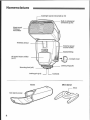
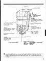
Nomenclature
-Catchlight panel [retractedy (p-79)
Built-in wide pare
(retraCled) (P.20]
Flash hea_dl
Wiraless
tranerniffer
emu:-S
l'
wireless sensor
II`~ ~
C
.ano71
~
~
I
E=terna3 power
source socket
I
Bracket fining
AF-assist beam emitter
P'47)
Contact cover
Mounting fool {p .9}
,
Lacking pin [p .9]
Case
_Locking ring [p.8]
Contacts
Mini stand
Shoe
8
Mini standpocket
I
\l
4
'.
LC bpanel
Bounce angle
,PUSH,
f3oimrc lock release
6ufton [p.18]
--a$:IC Fn :
~ .CD panel illumination..'
custom Furctiol setling
h~itton [p .&~27]
I I ~.~' ~SH~sn7
~ r'
-~i
High-Speed Sync (FPflash).+
Shuttercurtain syncnroniial3on
button (p t7"'26)
I ~
I I ~
Battery conrparl mem co+~:r
(p.8)
Zoom blrttnnl Wi rel¢ss set
button (p.20r3B, 37 .38, 39,
42)
-PILO7~ ____ .
f,ilo[ lam ~.+Testfiringl Wireless
slava zino ~croff cancel
Button (p . i0+35y
RUmcr switch (p.10)
,OFF> '. P~veroff
ON, : Pcsver an
Fleshexposure confirmation
lamp (P 11)
~(b~ , Select Dial
.MO QE~
Flash modelSla~
sei ti nqUuttan [p. :1
22,2442,43]
c`) n ScI ccVSet button
Wire
selector [p.9, 34]
<DFF±
:Wifelessoff[fnron-ramcraiiash]
:MASTERS : Master Unit
SLAVE :
: Slaw and
Asterisked buttons have a timer that keep the button's function active for
8 sec. [c38] after you let go of the buttorr. The < :b~> illumination lasts for
12 sec .
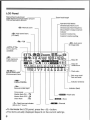
LCD Panel
Manual ilashnufput level
Flash BxpDSUfeCampensation amounl
FEB Compensation amounl
Zoom focal length
Aperture FEB status
Stroboscopic (12513 Grunt
manu l zoom
~19,
Stroboscopic flaslt frequency
Manual flash 113-stop irGmmen[
~IM~
~ High-speedsync_
[FPflesh]
indica'vr
~
Custom Function Na .
Custom Function salting
~~~ FE6
C" TTL (11)I TTL
avtoliash
~I
'...
ETTL
Flashexposure
com~nsation
e=> Auto room
for image sFze
i
<ETTLITTL,
-MULT[
ManualMiMuinflaslis."'+rluli
{Siroboscopic) ttash
Zoomi
D r88
mm El
1 z34 ~ .A:B :cI
Slave ID
~
-~
8 :'1 . 4 :1 4 .21 " 7 :1 ;. T :2, "
~w
r
~
~w~
0.5 0.7 7 1 .5 2 3 4 6 9
75 20 . 0
'~. . ' 1.7 23' 4 5 7 1
I-
slave io
7 :4 . 1 :8--~-~ underscore
~
13 78 m -l .
40 60 ft I~ :~ Flash ratio
FI3511 fang scale,
Fiasn raia scale
e~
Cd~ i
Cu stom Function
~Ct~>
;u rtai a sync
Second-
i
Indicator [meters]
i
Indicator (feel)
Firing mode
Master flash ON atN
Master flash OFF -. .A
flash ratio
Slave flash
c9> Flash Oaurtceindicator
(84nksfor7 dcsvn)
A> Slave
`~~5Channel
.TO illuminate the LCD panel, press the < ;& > button,
.The items actually displayed depend on the current settings .
Getting Started and
Basic Operation
Installing Batteries . . . . . . . . . . . . . . . . . . . . . . . . . . . . . . . . . . . . . . . . . . . . . . . . . .
Attaching to the Camera . . . . . . . . . . . . . . . . . . . . . . . . . . . . . . . . . . . . . . . . . 9
Turn on the Power Switch . . . . . . . . . . . . . . . . . . . . . . . . . . . . . . . . . . . . . 14
Fully Automatic Flash Shooting . . . . . . . . . . . . . . . . . . . . . . . . . . . . 11
Using E-TTL II and E-TTL Autoflash 9n the
Shooting iviodes . . . . . . . . . . . . . . . . . . . . . . . . . . . . . . . . . . . . . . . . . . . . . . . . . . . . 12
H To avoid over9ieating and deteriorating the flash head, do not fire rapid
bursts of more than 20 continuous flashes . After20 continuous flashes,
allow a rest time of at least 10 min .
Installing Batteries
Install four size-AA batteries
- '
I I
Open the cover.
4~~
o
~
7
`2.
Slide the battery compart monE cover as
shown by the arrow and open it .
~~~ d[9 .
Instal[ the batteries .
'`
'
- -rf=
~
~
.~
&
Make sure the + and -battery contacts are
correctly oriented as shown in the battery
compartment .
q.
Close the cover,
--~1-:=
a Close the battery compartment coverand
slide it as shown by the arrow.
Recycling Time and Flash Count (with size-AA alkaline batteries)
Recycling Time [A pprox .]
Quick Flash
Normal F18sh
_
Fl as h Count (aRProx~)
0.1 -3
0.1 -6
100 -70o
~ Based pn new sire-AA alkarine batteries and Canon's testing standards
. Quick flash enables a flash to be fired before flash-ready [p.79] .
N Sine the shape of their contacts is not standardized, using non-alkaline size-AA
balterios may result in foully battery connection .
o Lice four new batteries of the Sam E-brand and type . do not mix battery types . When
replacing batteries, replace all four batteries al the same timeo Site-AA Ni~MFf or lithium batteries can also be used .
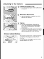
Attaching to the Camera
Loosen the locking ring .
'-
w
-- - ~~
Attach it to the camera .
s Slip the Speedlite's mounting foot all the
way into the hot shoe .
.x
--~
L
Turn the lacking ring as shown 6y the arrow
to loosen it .
/~',
._
,"
-_
-
3
-- ~~
Tighten .
A
;
Turn the locking ring as shown by the
arrow. The locking pin will protrude from
the mounting foot to further secure the
attachment .
a To detach the Speedlite, loosen [he locking
ring until the looking pin disengages . Then
slip the Speedlite out of the hot shoe .
-J
Wireless Selector Settings
~ti'~ :r : i ..._ -OFF
~'
JSLAVE
MASTER
-LOCK
' i
The wireless selector is for switching between
normal flash shooting and wireless flash
shooting.
For normal flash shooting, be sure to set the
wireles selector to < flFF> .
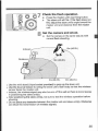
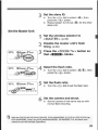
Turn on the Power Switch
Set the power switch td <ONa .
o- The flash will start recycling .
Check that the flash is ready.
*
The pilot tamp will first turn green [ready for
quick flash], then red (fully recycled or flash
ready) .
w To fire a test flash, press the pilot lamp .
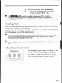
About Quick Flash
Quick flash enables aflash to be fired before flash-ready, when the pilot lamp
is still greenAlthough the Guide Na. will be 116 to 112 that of the full output, quick flash is
effective for near subjects and when you want a shorter recycle time .
Set the drive made to Single . Quick flash cannot be used in the continuous
shoaling . FEB, manual flash, and stroboscopic flash modes.
About Auto Power Off
To sage battery power, the power will turn off automatically after 90 sec. of
idle use. To turn on the Speedlite again, press the shutter button halfway.
Or press the Speedlite's test firing button .
LXl
10
R A test firing cannot 6e fired while the camera's operation timer (1A or CAS is active .
~" The Speedlile's sppings will be mlained in memory even after the power is turned off.
7o retain the Speedlite's settings when you replace the batteries, replace the batteries
within i minute after turning off the power,
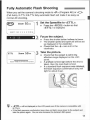
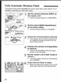
Fully Automatic Flash Shooting
When you set the camera's shooting mode to < P> [Program AE] or cps
(Full Auto), E-TTL IIIE-TTL fUl1y autflmatic Tlash will make it as easy as
normal AE shooting .
TTY
R.5 a' 1
Zoom 5U'mm
i .5
z
3
s
s
9
, °`Set the SpEBdlite to [ETTL> .
Press the <MODE> button so that
--ETTL> is displayed .
i3 19 m
`'
Focus the subject.
.^.
.-
9
ETTL
zoom 5u,mm
0.5 0.7 1 1 .5 Z 3 - 6 9 13 1s m
`l
.
Press the shutter button halfway to focus
The shutter speed and aperture will be set
as displayed in the viewfinder.
Check that the < J > icon is lit in [he
viewfinder.
Take the picture.
~~
[9,
.'
Check that the subject is within the
effective range displayed on the LCD
panel .
A preflash is fired right before the shot is
taken, then the main flash is fired .
If a standard flash exposure was obtained,
the flash exposure confirmation lamp will
light for about 3 sec .
/ -
'CD
: . : .t~. . L
LEI c < E -{TL ~ will be displayed on the LCD pane[ even if the camera is compatible with
E-TTL II .
~. Lf the flash exposure confirmation lamp does not light, mope closer to the subject and
take the picture again . You can also increase the camera's ISD speed .
11
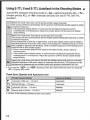
Using E-TTL II and E-TTL Autoffash in the Shooting Modes m
Just set the camera's shooting mode to c Av> (aperture-priority AE), a1'rr>
[shutter-priority AE], flr <M> (manual) and you can use E-7TL IIIE-TTL
autaflash .
Srk :rt this mode when you want to set the shutter speed manually
.
The camera will Then automatically set [he apertura matching the shutter speed to obtain
:i standard exposure .
v ~, if the spar hure display Minks, i[
means that the background exposure will be
underexposed or o+lerexpnsrsd . Adjust the shutter speed until [he aperture display
stops blinking .
Select this mode when yon want to set the aperture manually
the camera will then au rornatically set the shutter speed matching the aperture to obtain
a standard exposureIf :he background is dark like a night scene, a slaw sync speed will be used to obtain a
standard exposure of both the main subject and background . Standard exposure of the
m ain subject is obtainn:d with the flash, while a standard exposure of [lie background is
AY o'utained with a show shutter speed5 ince a slaw shutter speed will be used for low-light scenes, using a tripod is
recommended.
.: If the shutter speed display blinks, i[ means that the background exposure will be
. Adjust the aperture until the shutter speed display
underexposed or overexposed
slops blinking .
Select this made when you want to set ]path the shutter speed and aprriura manuaEly,
Standard exposure of tfhe main subject 7s obtained v:i[h the flash. The exposure of tfie
background is obtained with the shutter sper:d anti aprrturp combination you set.
a I[ you use the ,D EP a or c {l-DEP> shooting mode, the result wiu be the same as using the
tP> (Program AE) mode.
Flash Sync Speeds and Apertures Use
Shutter Speed Setting
Aperture Setting
Automatic [11a0 Se[:. - T?H sec,j
Automatic
TV Manual [30 sec . - ]!X sec .)
AY Automatic (30 sec . - 11X sec .]
Manual (bulb, 30 sec . - ilx see .)
& i1X sec . is the camera's maximum flash sync. Spocd .
12
Automatic
Manual
Manual
r
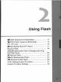
Using Flash
Flash Exposure Compensation . . . . . . . . . . . . . . . . . . . . . . .
14fi FHB (Flash Exposure Bracketing) . . . . . . . . . . . . . . . . . . .
FE L FE Lock . . . . . . . . . . . . . . . . . . . . . . . . . . . . . . . . . . . . . . . . . . . . . . . . . . . . . . . .
m High-Speed Sync (FP Flash) . . . . . . . . . . . . . . . . . . . . . . . . . . .
Bounce Flash . . . . . . . . . . . . . . . . . . . . . . . . . . . . . . . . . . . . . . . . . . . . . . . . . . . . . . . .
ZOOM Setting the Flash Coverage and Using
the Wide Panel- . . . . . . . . . . . . . . . . . . . . . . . . . . .--- . . . . . . . . . . . . . . . . . . . .
M Manual c=lash . . . . . . . . . . . . . . . . . . . . . . . . . . . . . . . . . . . . . . . . . . . . . . . . . .
MULTI Stroboscopic Flash . . . . . . . . . . . . . . . . . . . . . . . . . . . . . . . . . . .
CWSecond-Curtain Sync . . . . . . . . . . . . . . . . . . . . . . . . . . . . . . . . . . . . . .
14
15
1s
17
18
20
22
24
26
C .FCt Setting Custom Functions . . . . . . . . . . . . . . . . . . . . . . . . . .- 27
Custom Function Settings . . . . . . . . . . . . . . . . . . . . . . . . . . . . . . . . . . . . 28
13
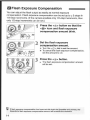
CR Flash Exposure Compensation
You can adjust the flash output as easily as normal exposure
compensation . Flash exposure compensation can be set up to ± 3 stops fn
113-stop increments, {If the camera enables anly 112-stop increments, then
only 112-stop increments can be set.}
=- 7
rr
~
Press the ¢0
. > button so that the
<0> icon and flash exposure
compensation amount blink .
i ~ .
uy
Set the flash exposure
compensation amount.
* Turn the <> dial to set the amount .
" To cancel the flash exposure compensation,
set the amount to +D .
Ilo' I ~--` ,
,i
~ `
«-r~ ...F
I
4
Press the <(~)n button .
-:
p The flash exposure compensation amount
will be set .
If [lush exposure compensation has been set with both the Spoedlite and camera, the
Speedlite's flash exposure compensation amount will override the camera's .
14
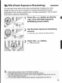
W,!3 FEB Flash Exposure Bracketing)
~i
You can take three flash shots while automatically changing the flash
output far each shat up to *3 stops in i13-stop increments {112-slap
increments if the camera enables only 112-stop increments}. This is called
FED (Flash Exposure Bracketing).
Press the <~~> button so that the
<WA> icon and flash exposure
bracketing amount blink.
-
IJ ~-
Set the flash exposure bracketing
amount .
* Turn the r F)> dial to set the amount .
r
I ~
. .
I
Press the ¢~)> button .
FEB will be set.
m After all three shots are taken, FEB will be canceled .
. The Shols vall be taken in the drive mode set with the camera .
~ For FEB shooting, set the camera's drive made to Single shooting and be sure the
Flash is ready before you shoot.
~ You can also combine FEB with flash exposure compensation and FE lock .
15
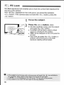
FE L FE Lock
FE (flash exposure) lock enables you to lock the correct flash exposure for
any part of the picture.
With < ETTL~ dispEayed on the LCD panel. you press the camera's
<FE L> button . If tie camera does not have the -.FE L> button, press the
cg(-a button .
Focus the subject .
,-
--
-----
Press the aF EL > button . {aTS}
Aim the viewfinder center over the subject
and press the aFEL> button,
s A preflash will be fired to obtain a flash
exposure reading for the subject .
~ "FEI:' will be displyed on
0 .5 sec .
s each tame you press the
preffash will be fired and
exposure reading wilt be
the LCD panel for
aFE L > button, a
a new flash
lacked .
H ~ If the subject is too far away and underexpOSUrp will result, the c ~ > icon wit! 6fink in
[lie viewfinder. Mope closer to the subject and try the FE lock again .
~ If ~ETTL - is no[ displayed on the LCD panel, FE lock wilt not be possible
.
. !f the subject is too small, FE Inck might not be very effective.
16
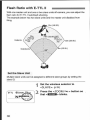
m High-Seed Sync (FP Flash)
With high-speed sync, you can use flash with all shutter speeds . This is
.
convenient when you want to use aperture priority for fill-flash portraits
-er7 ~
zoom 5~mm -~
03 A7 1 1.5 2
3
4
6
9
13 16
m I
Press the C~HICC1i a Button so that
<m> is displayed .
a Check that the a~Ha icon is lit in the
viewfinder,
s Stroboscopic flash cannot be set,
s if you set a shutter speed that is th0 same or slower than the camera's maximum flash
sync speed, 4 fH> wil not he displayed in the viewfinder.
e With high-speed sync, the faster the shutter speed, the shorter the effective flash
range will be . Check the NCO panel for the effective flash range .
. TO return !a normal flash, press the < SHI fIs > button so that c m : icon turns off .
17
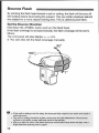
Bounce Flash
By painting the flash head toward a wall or ceiling, the flash will trounce off
the surface before illuminating the subject. This can soften shadows behind
the subject for a more natural-looking shot . This is called bounce flash.
Set the Bounce Direction
Hold down the <PllS}i> button and turn the flash head .
It the flash coverage is set automatically, the flash coverage will be set to
50mm .
The LCD panel will also display c- -> mm .
a You can also set the flash coverage manually-
0 w If the wall or ceiling is too far away, the lwunced flash might be loo creak and result in
underexposure* 7h G wall or ceiling should he a plain, white eolorfor high reflectance . If the bounce
surface is not white, a color cast may result in the picture* After you take [he shot, if the !lash exposure confirmation lamp does not fight, use a
larger apersure opening and try again .
18
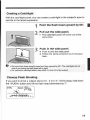
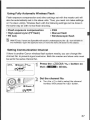
Creating a Catchlight
With the catchlight panel, you can create a catchlighF in the subject's eyes to
add life to the facial expression .
Point the flash head upward by 90° .
Pull out the wide panel .
0, The catchlight panel will came out at the
same time .
I
3
push in the wide panel.
* Push in only the wide panel.
s Follow the same procedure as for bounce
flash .
:.332?2" :,. .
_
. . . ._
--
--
. . .a`7Ja... . .
. . J
N ~ Paint thu flash head straight ahead and then upward lay 90°. The calchlight will not
work if you swing the flash head left or right.
.
~ For maxi murn catch light effect, stay vliqiin i .5 mlR,g ft of the subject
Claseup Flash Shooting
If you want to shoot a subject about 0.5 - 2 m (i .fi - 6.6 ft) away, hold dawn
the <PU5H> button and tilt the flash head downward by 7° .
E77
0.50]
5umm
F-5.b
l
1.57li\~~13 18
m
19
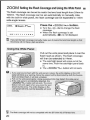
ZOOM Setting the Flash Coverage and being the Wide panel m
The flash coverage can be set to match the lens focal length from 24mm to
105mm . The flash coverage can tae set automatically or manually. Also,
with the built-in wide panel, the flash coverage can be expanded to 14mm
wide-angle lenses .
~ETTL
m Zoom ~~Imm ~
.5 0.7 1 1.5 2 3 ¢ 6 9 ~3 18 mJ
LEI
Press the ¢ZOflM 1- .> button .
0 Turn the r@ > dial to change the flash
coverage .
o When the flash coverage is 59t
automatically, <pn is not displayed.
If you set the flash coverage manually, make Sure it covers the lens focal length so that
the picture will not have a dark periphery.
Using the Wide Panel
--
`
- '
-
Pull out the wide panel and place it over the
flash head as shown. The flash oaverage
will then be extended to 14mm .
s The catchlight panel will come out at the
same time . Push the catchlight panel back
in .
v The r20flM 1'z+ > button will not work .
H m If you use bounce flash with the wlde panel in place, the entire display on the LCD
panel will blink as a %%-or ning. Since the subjec[will6e illuminated by loth the bounce
flash and direct flash, it will loch unnatural .
9 Pull out the wide panrsl gently. Using excessive force may detach the wide panel .
b If the vide panel is accidentally r3efached, the
c
_
700M I 'z, > button will not work. The zoom
-------------feature will work again when you press the spot
` :-'=shown
6y the arrow. The entire display on the
.
LCD panel will blink, but the Speedlite will work
normally.
11 The flash coverage will notbe compatible with the EFi5mn f12 .8 Fisheye lens.
20
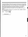
Automatic Setting of Rash Cove rage for the Camera's Image Sire
EMS digital cameras have one of three image sizes. The lens' effective focal
length will differ depending on the camera's image size . The 5peedlite
automatically recognizes the EMS digital camera's image size and
automatically sets the flash coverage for lens focal lengths from 24mm to
105mm.
When the Speedfite is attached to a compatible camera, c9HD> will appear
on the Speedlite's LCD panel.
ETTL
t
Zoom ~um~
__7 i's 72,2 77279 1112 .
l
21
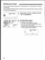
M Manual Flash
You can set the flash output from 11928 power to 111 fu l[ power in 113-stop
increments .
Use a hand-held flash meter to determine the required flash output to obtain
a correct flash exposure .
zoom 5"m~
!1 i
~
'
0 . 5 07
1
i.5 2
3
4
6
9
13 1,
2
M
Press the ¢MODE> button so that
<M> is displayed .
~ ~o~ )m _
-
Set the flash output .
c, Press the ~`~a button .
m The flash output display will blink.
& Turn the < ~> dial to set the flash output,
then press the c(~> button
.
a Press the shutter button halfway to see the
effective flash range displayed .
loam r?umm
~l v
M
0.50.7
22
1
1.5 2
3 0 6
9
13
15 m
Displayed Flash Output Figures
When you change the flash output during shooting, the table below makes it
easier to see how the stop changes such as 112 -4 .3 -~ 112 -* 112 X0 .3 . You
can see how the slap changes when you increase or decrease the flash
output .
For example, when you decrease the flash output to 1l2, 1/2 -0 .3 . or 1/2 -0-7,
and then increase the flash output to more than 112, 112 +D .3, 112 +Q .7, and
111 will be displayed.
Sample Flash Output Figures
11i
1!1 -0 .3
il2+0.7
Figures for decreased flash output
111 -0.7
112+0.3
112
1!2 -0 .3'
1/4 +0 .7
F Figures for increased flash output
1!2 -0 .7
1i4+~.3
714
23
MULTI Stroboscopic Flash
With stroboscopic flash, a rapid series of flashes is fired . It can be used to
capture multiple images of a moping subject in a single photograph for later
study.
You can set the firing frequency {number of flashes per sec. expressed as
Hz}, the number of flashes, and the flash output .
Press the < M0oEa button so chat
<MuLri> is displayed .
doom
uin
asa.v , rs z s a s s is is m
Ii
fl
I
+
=:.
LC'=-
?k,.
1
,>>,
Select the item to be set.
~ Press the < ~~y button to select the item
(blinks) .
y ":sm 5Fi m+y i 1
I2 B --inz
J.~
Set the desired setting .
..
.
_
a-.
i{Omm
~~~~-=Panr~
~~s,":
.~
,1r28---- . ~N~
s Turn the ~~~a dial to setthe setting, then
press the < %:> button .
" The next item to be set will blink.
s After you set the ti ash output and press the
< [?n button, the entire display wild turn on .
Calculating the Shutter Speed
During stroboscopic flash, the shutter should remain open until the firing
stops. Use the formula below to calculate the shutter speed and set it with
the camera .
Number of flashes = Firing frequency (Hz) = Shutter speed
Far example, if the number of flashes is 10 and the firing frequency is 5 Hz,
the shutter speed should be at least 2 sec.
24
To avoid o\~~erheating and deteriorating the flash head, do not fire mare than 10
stroboscopic bursts. Then allow thQ Spaedlite to rest for at least 10 min.
L1
- Stroboscopic Flash is mast effective wish a highly reflective subject against a dark
background .
* Using a tripoJ, a remote ssviECh, and external power source is recommended .
" A flash output of 1!1 or 1!2 cannot 6e set for stroboscopic flash .
. Stroboscopic
flash ran 6e used with "buLb-"
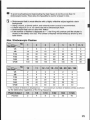
o If the number of flashes is displayed as--, the firing will con:irtue until the shutter is
closed or the battery runs out. The number of flashes will be limited as shown 6y the
table below.
Max . Stroboscopic Flashes
Flash Dufpv~
~s
114
9l8
1116
7132
1164
11128
Hz
1
2
3
4
5
fi-7
8-9
7
14
30
60
90
100
6
14
3D
80
90
100
5
12
30
60
90
~
11
8
100
20
54
89
100
3
6
20
40
70
90
3
5
10
30
60
80
-
10
20
50
89
100
10
11
72-74
75-19
20-50
6D-199
114
2
2
2
2
P
2
118
4
4
4
4
s
4
B
20
50
S
20
40
8
20
40
8
18
35
8
16
8
52
20
Flash OvrtpLt
1116
1132
1164
1/128
1
70
f
70
f
60
1
50
~
30
40
~
43
o If the number of flashes is displayed as--,'he insxirrwrn nurriber Of flashes will be as shown
by the table t:rlnv: regardless of the firing frequency.
'
Flash .0utpuY
Flash es
114
2
_
118
4
~
1110
8
1132
12
1164
20
11128
40
I
25
M/Second-Curtain Sync
With a slow shutter speed, you can create a light trail following the subject .
The flash fires right before the shutter closes.
ETTL
n
v
Zoo
Press the sfNI cef> button so that
<fx" > is displayed .
4 Stroboscopic flash cannot be set .
9s 0a , 1s 2 3 4 6 9 13 is m J
Lyl ^.. Setting the shooting mode to "bulb" will make it easier for second-curtain sync .
e To return to normal flash, press the c'sH 1 CIA > button so that the < Mlll~ > icon turns
Off.
With E-TTL ISIE-TTL, the flash will fire twice even with a slow sync speed . The first
hash is the preflash.
26
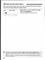
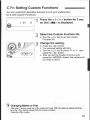
C .Fn Setting Custom Functions
You can customize Speedlite features to suit your preferences.
Do it with Custom Functions.
Press the ¢=B:IC .Fn7 button for z sec .
so that <30> is displayed .
N
Select the Custom Function No .
~~ Turn the <['~)> dial to set the Custom
Function No.
3 Change the setting.
Press The <4;> button .
'
k' %'`Y -F' ` ~ ` " ' "
-
The seleciec i setting will blink .
~ Turn the ~'> dial to select "0" or "1", then
press the <.'a button .
After you set the Custom Function and
press the -_MflD E> button, the camera will
be ready to shoot.
Changing Meters or Feet
After step 1 above, press the < r,~)> button for 2 sec . With the distance display blinking,
turn the < ~"> dial to change the unit to feet or meters .
Press the c ~: , button .
27
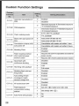
Custom Function Settings
!unction 1
C
1
C .Fn-02
F
C .Fn-03
C . Fn-Od
Automatic cancellation of
FEB
Flash metering mode
Slave units auto power off
time
Cancellation ofslaveunit's
auto power off
C .Fn-0&
Modeling Flash
C .Fn-07
Flash recycling method
when exlernal power
source is used
C .Fn-08
Quick Ilash with
continuous shooting
C .Fn-09
Test firing with aufoflash
C.Fn-10
Modeling flash with test
' firing button
i Eriablad
I
Disabled
Standard exposure a decreased exposure
-P increased exposure
: DeCreaSBd expo3urp i Standard exposure
~ Increased exposure
D
I E-TFL fllE-TTL autoflash
C.Fn-11
Auto setting of flash
coverage to match
C.Frt-12
AF~assrst beam OFF
C. Fn-13
Flash exposure
compensation soiling
method
C.Fn-14
Auto Rower off activation
camera's image size
-
-
1
TTL aUtO11a5h
a
Auto passer off after 60 min .
1
Auto power off offer 10 min-
a
Cancellable srifh master unit within 1 hour
i
Cancellable with master uni[ within 8 hours
0
Enabled
1
Disabled
Recycle with both the Speedlite and external
power source
1
' Recycle with only the external power source
0
disabled
1
enabled
1
Full output
o
I
Setting Description
0
FEB seyuencc
C .Fn~05
28
Setting
Item
No .
__
V'.3z
-D
Disabled
1
Enabled
0
Enabled
1
disabled
0
disabled
1
~ Enabled
4
Set with < 6D > button and
1
Set directly with cF~ } .
0
On
1
Off
dial .
C.Fn-06 : Convenient when you want to check the depth of field . (p-41)
C.Fn-07 : If bash the external power source and the Speedlite's internal
batteries are used to recharge the flash, both power sources will
be used together. FioweVer, if the internal batteries become
exhausted, shooting may be disabled . If 1 is set, only the external
power source will be used to recharge the flash and the internal
batteries will be spared . Note that even it you set it to 1, the
So eedlite will still require internal batteries far flash control .
+ C- Fn-03-1 is a setting for IF OS-1 series film cameras only.
Do not use this setEing it you have an EDS digital camera or E05 REBEL T2.+300H .
With an EOS digital camera or EpS REBEL T2130OX, this setting will cause improper
flash control-the flash might no! Fire or it may fire only at full output .
:n I! you use a Type-A camera and set C.Fn-Q3-1, wireless auto7lasn will not work .
:. If "AF-assist beam OFF" is set with the Speedlite or camera, the AF-assist team will
not be emitted .
If you use a Type-B camera and set C .Fn-03-4, E-TTL I IIC-TTL autoflash will net work .
29
s;~:;=~: . ;~Y
-
-
~
,
.~ .
.7~' _
i
.
.
.. .
. . ..
::
Wireless Flash
About Wireless Flash . . . . . . . . . . . . . . . .- .----- . . . . . . . . .. . . . . . . . . . . . . . . . .
Fully Automatic Wireless Flash . . . . . . . . . . . . . . . . . . . . . . . . . . . . . . . . . .
Flash Ratio with E-TTL II . . . . . . . . . . . . . . . . . . . . . . . . . . . . . . . . . . . . . . . . . . . .
Wireless Manual Flash with Varied Flash Output . . . . . . .
Setting Manual Flash and Stroboscopic Flash with
the Slave Unit . . . . . . . . . . . . . . . . . . . . . . . . . . . . . . . . . . . . . . . . . . . . . . . . . . . . . . . . . . . . .
32
34
38
42
43
31
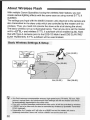
About Wireless Flash
With multiple Canon Speedlites having the wireless flash feature, you can
create various lighting effects with the same ease as using normal E-7TL II
autoflash.
The settings you input with the 580E?C master unit) attached to the camera are
also transmitted to the slave units which are controlled 6y the master unit via
wireless . Thus, you need not operate the slave units at ail during the shoot.
The basic wireless set-up is illustrated below. Then elf you do is set the master
unit to < ETTL> and wireless E-TTL If autoflash will be enabled (p.34) . Note
that with Type-A cameras prior to the Cfl5-10 Mark 11 and EOS ELAfV 7N E/
FLAN 7N/30V/33V, E-Tf'L autoflash will be used instead .
Basic Wireless Settings & Setup
indoors
~ ~
Outdoors
1l
~i
i5m (49 .28 .)
10m [32 .8ft .]
J
8m (26.2ft .)
12m (39 .4tt.)
P Any clash exposure compensation amount, high-speed sync {FP flash}, FE lock, FE 8
amount, manual flash, and stroboscopic flash settings set with the master unit will all
he automatically transmitted to the slave units .
a Even with rtiu[tiplr; Speedlies positioned as slave units, elf will be controlled by vrireless .
e A SSOEX set as a slave unit can also he controlled by wireless by Speed lite Transmitter
STE2 (optional) .
. Hereinafter, the "master unit" will refer to a 580Ex se[ as the master unit. and a
wirelessly-Cnnirofled "slave unit" will he a 580 EH set as the slave unit .
32
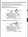
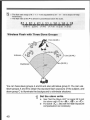
Multi-5peed[ite, Wireless Lighting Configurations
You can crate t%yo or three slave groups and set the flash ratio fn r E-TTL II
autafiiash shooting (p.38 - 42).
Wireless flash with two slave groups [p.38]
1sm (49-21 t.)
Outdoors
Sm [26.2ft.]
12m (39 .4ft .)
Wireless flash with three slave groups (p.40)
Indoors
outdoors
15m [49 .2ft.]
C
' lOm (32 .8f1.)
yS
I
8m (26 .2f1 .)
12m [39 .4ft .]
33
Fully Automatic Wireless Fish
This method has all the Speedlites fire at the same clash output with E-TTL Il
autaflash controlling the total flash output.
I OFF
Set the camera-attached 580E7( as
the master unit .
SLAVE,
MASTER
a
TL
OFF
=
MASTER
SLAVE
....
m Zoom 2`1-1
~ETTL
Set the wireless selector to <MASTER> .
IM Zoom 24 ,
~T-ru] Zoom C~4mm
A
Set the
slave 580 EX Speed lites(s)
as the slave unit(s).
0 Set the wireless selector to <SLAVE> .
Check the communication channel.
~ If the master unit and slave unit(s) areset
[a a different channel, set them all to the
same channel [p.37].
Position the camera and 5peedlites
as desired .
~
Position the Speedlites within the range
shown on the next page.
Set the master unit's flash mode to
<ET7L> .
9 The slave unit(s) will also be automatically
set to <ETTL> .
16 Check that tie flash is ready .
r
2/21
34
i-
When the slave unit is ready to fire, the AFassist beam will blink once each second .
C 7 e~
Check the flash operation .
8
Press the master units test firing button.
The slave .unit will fire . If the flash does not
1i re, adjust the slave unit's angle toward the
master unit and distance from the rnasler
unit-
Set the camera and shoot .
Set [he camera in the same way as with
normal flash shooting-
15M [49 .2ft.]
Outdoors
8m (26.2Ft .)
12m [39 .4ft.]
o Use the mini stand [tripod socket provided] to prop up the slave unit .
e Use the bounce feature to swing the slave uniYs flash body so that the wireless
sensor laces the master unit .
a Indoors, the wireless signal may also bounce off the wall so there is more IeFway
in positioning the slave unit(s)After positioning the slave unit(s), be sure to test the wireless operation before
shooting .
m Do not place any obstacles between the master unit and slave unit(s)..Obstacles
can block the transmission of wireless signals.
35
LXl
~ The Speedlife's zoom set[ing will 6e set automatically to 2hmm . ]t is possible to change
the ma8t(:r unit's zoom setting . Wov:EVer, npte that the master unit transmits v+ireless
signals to [die slave unit(s) with :he preflash . Therefore, the flash coverage must cover the
slave units position . If you change [he
master units room setting, be sure to test the
wireless oppraiion before shouting .
u IFthe slave unit enters auto power off. it can 6e turned on again t~v; pressing the master
unit's test firing button .
* A test flash candor 5o fired while the camera's operation simer 64 or 66 is active.
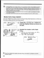
Master Unit's Flash ON/OFF
You can disable the master unit from firing during actual exposure so that only
the slave unit(s) will fire in the final picture.
rE771
D Zoom,~'imm ~
-ori-
-~ ~i i `
5%0. 'IT
..±(~Tfl,7lTl
-o FF-
Press the <ZOOMI'= .a button so
that the display blinks as shown on
the left .
Disable the master anti's flash
tiring .
2~{
k
Turn the < ;a dial to select <e
then press the r0> butEon .
FF >,
The <'M> iron will blink.
ETTL
IM Zoom L'imm
.-i .--
L~1
36
Even if you disable the master units flash firing, it will still fire a preffash to transmit
vrirelpss signals .
Using Fully Automatic Wireless Flash
Flash exposure compensation and other settings set with the master unit will
also tie automatically set in the slave units. Thus, you need not make settings
on the stave unit{s}. Wireless flash with the following settings can be done in
the same way as with normal flash shooting .
" Flash exposure compensation
" High-speed sync [FP flash]
" FE lock
Lyl
" FHB
" Manual flash
" Stroboscopic flash
Wifh FC lack. if even one Speediite will resuiE in underexposure, the < f 7 icon will blink in
the viewfinder. peen the ape rEUre mare or move the stave unit closer to the subject.
5etiing Communication Channel
If there is another Canon wireless flash system nearby, you can change the
channel No . to prevent signal confusion . Bath the master and slave units must
be set to the same channel No.
IETTL
DZoom 2'irnm
~Ii1C,n
, 7
z.F 1
1 3 '1~-
Press the ¢ZOOMI'x, > button so
that
blinks .
i
---
Set the channel No .
~
Turn the ~O
.> dial to select the channel
number, then press the <(, ; a button-
i ~Q loom 21
7
37
Flash Ratio with-E-TTL 11
With one master unit and one or two slave units off-carnera, you can adjust the
flash ratio far E-TTL I[ autoflash shooting .
The example below has two slave units and the master unit disabled from
firing .
15m (49 .2ft.)
R T"
'i0m (32 .8ft~
Indoors
A ~
Dutdnors
4
80"
12m (39 .4tt .)
Sm {2621t .}
Set the Slave Unit
Multiple slave units can 6e assigned to different slave groups by setting the
slave I b.
Set the wireless selector to
¢SLAVE> . (p .34)
ETTL
M Zoom
m
~'A-
38
Press the <ZOOM 1't4 >hutEon so
that < ~a blinks .
_
3
Set the slave In .
s
*
Turn [he
press the c
dial to select rA>, then
I button .
Repeat siepsl to 3 to set c ga for [he other
slave unit .
Set the Master Unit
`
Set the wireless selector to
<MA5TER> . (p.34)
Disable the master unit's flash
~J firing . [p.3s]
~ETTL
~'
LTUI24-
Press the C ZOO MI'z+7 button so
~' that < ~> blinks .
~a FF=
,r ~
1 l I
-°L=~ 1
~4
J
rETTL
ETTL
0200F
5o lect the flash ratf0 .
2Ymm
-01
ui2oam 2YMm
-~ -f
-10
Turn the <~~~>dial to select c A : $ >, thin
press thQ < Q n button .
, C~: Set the flesh ratio .
c~r Turn the <of >dial to set the Ilash ratio
"
~A; B
i
-f:z. -ft
6 Set the camera and shoot .
,,it
Cyl
Set the camera in the same way as with
normal flash shooting .
With the EOS ELAN IJELAN II EJ59150E, EOS 500WREBELG, EDS IX . EMS IX711X Lite .
Ep5 3001R r: BE L 2p00 : and Ep53QQQN1661REBEL XS AfIREBEL G II, the flash ratio
cannot be set with in ultip 1e Speedites.
39-
a The flash ratio range of 8 :1 - i :1 - 1 :8 is equivalent to 3:1 - 1 :1 - i :3 in stops [112-slap
increments] .
a The flash rr31i0 at the 0 is shown in parentheses below the scale.
8 :7 . 4:7 . 2 :1 - 1 :7 . 1 :2 . 1 :4 + 1 :8
~ ~ ~ ~ rw ~ rr rr~r~ wiwi ~rrrrr ~
{5 .6 :1}
(2-8'1)
[1-4 :5]
(1 :1 .4)
(t :2 .8)
{1 :5 .6}
Wireless flash with Three Slave Groups
15m (49 .2ft.)
iCm {32.831.]
indoors ( H ~
Outdoors
,
~ 8
)i2m (3s .ats .)
JSm (2f .2it .)
----$C,
/
You can have slave groups A and 8 and also add slave group C. You can use
slave groups A and 8 to obtain the standard flash exposure of the subject, and
slave group C to illuminate the background to eliminate shadows.
Set the slave units.
o See "Set the Slave Unit" on page 38 to set
the save units ID to < A>, <B >, Or < C>,
0 Far slave cC>, also set the flash exposure
compensation-as necessary.
40
Set the master unit and shoot .
2 o See "Set the Master Unit' on page 39 .
In step 4. select <A : B C
H a If <
181 : B ~ is set, the Speedlite in slave gfoup a[7 will not fire .
m Ii you point the slave group c [ > Speedlite toward the subject, the subject will be
overexposed .
Modeling Flash
If the camera has a depth-of-field preview button, press it to fire a 1 -sec . burst
of flashes . This is the modeling flash.
You can check the lighting and shadow effects. You can fire the modeling flash
for both wireless and normal flash shooting .
H Do not fife the modeling flash more than 10 consecutive limes. I# you fire the modeling
flash 90 consecutive limes, allow the Speedlita to rest far at least 7d min . to avoid
overheating and deteriorating the flash head.
The modeling flash cannot 6e fired with the Ed5 300iREBEL 2400 and Type-8 cameras
(P .2) .
About Slate-Group Control
Slave group A
-----/r
}
,
Id ~ `
\
for example, if you have the slave Ib set
to ¢A> for three Speedlites, all three
5peedlites will 4e controlled as if they
were one 5peedlite in slave group A .
_--
41
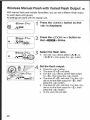
Wireless Manual Flash with Varied Flash Output m
With manual flash and multiple Speedlites, you can set a different flash output
for each slave unit {group} .
All settings are done with the master unit .
Press the ¢MQQEa Button so that
<M> is displayed .
D room 24mm
r~,za?m
-ate ~ i ~~
z
`II , ~ _
-rte
1~~
Press the < ZOOM 1~.> button so
°~ ' that ¢~> blinks .
-
J
G9 zoom,2%m
~an-
.z .7
=~,
Select the flash ratio .
~: Turn the <~ > dial to select <A= B> or
~A= B : Cam, then press the cJa button-
A- Set the flash output .
Press the <:'y> button .
I
"
:~.am 2`fmm
,
'-^`
a
@
The slave la < A > w ill bli n k .
Turn the <0> dial to set the flash output
far <A>, then press the < Q> button .
The Slave ID c $ > will blink . Turn the
dial to set the flash output far <-B>, then
press the <`?> button .
The slave ID c C a will blink . Turn the
m
42
dial to set the flash output for <9;>, then
press the a;~?> button .
All the slave IDs will tight .
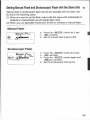
Setting Manual Flash and Stroboscopic Flash with the Slave Unit m
Manual flash or stro4oscopic flash can be set manually with the slave unitDo this in the following eases:
(7) When you want to set the flash output with the slave units individually for
wireless or manual flash, as with studio clash units.
{2} When you use 5peedlite Transmitter ST E2 forwireless or manual flash .
Manual Flash
D Zoom
2Y--
a
s
Press the <MQbE> button for 2 sec .
<M>will blink.
a
i-
Press the <MQdE> button for 2 sec .
.
<M> will blink
w
Set the manual flash output (p .22)-
Stroboscopic Flash
a "
Magi-
p zoom 2'imm
"1128 .5- ^ [I~,~
w
s
Press the <MflDE> button again and
<MULTI> will blink.
Set the stroboscopic flash [p .24] .
43
.,
]
~
~
n
. .
~r~
. ..-..:'.5 .
...:
. :'' .
z 3~"
y
.v._9 . . .:
r _
. .
r. .. .
~i
.
.
..
.
.
i.
h . .
. . . . ... . .. : ~ . n
S % I
..
.~
:
.
y.
. . .. .
.e i. .I .
: " .. .~ .
r. .,. ,..:
. .....,. .,. .
. .
, ,.
; . .~ :
z.
. . ..
. . . .-e
. . . . '.
:: .
. ..
.
:v.,. .
. .,
'
..
.1'
. ...
..
..
~
, . . . . . . x
. ..
_ :. . .
. : .. .
r
6
. .
., . e
. 4
~
. . .! . . ..
.. . . . .
.r
~. ..
..~ .
V.
y
. . :,r . . :
y{!: ...
. :,. .,
kn . .~p , .x. . .
F,
.:
.
. .. .
. ~
s
. .' °'.~.
. ;' : .
.
e .~~ ;: .y . ..': . ;
egg r
L
.. .
e :.
,f
§~
=
i .i
xY'
.~~ h. .. . .
~,
a
a
.F
j~
..
. .
1~
l :~r.
..
`' p ~,
~S .
r~ r
.
=7~` :. .
~~Ii
~'!
3
i4
:t
JL:i
s51~1n':1" . !iE!
i
low!
~~
., ~
~ .fiN .
. ya .
mm1PS.~_~
`~.
.
; . ~ . .~ .. ~l
~'s''~
". .k~~
. Y~:
k.
',. .,.
:A: '
!P' :
,~.
~; .
.:
-
t
~ " Vi
'.~ i ..::
.
v~.L . . .
R S.
I -. :r
~
,y
l
. .
V v=
... ,
~q'~1"
.!
, .I ..e.
. ..
,.
;..
y J
ik: i ~:.
.t .
:d
..
P .
ay
rk
!Fi~~'
a
S.
yi
p
h
.r. , .s
..
Ib. ... . . . . .
.
. .'
.`~a
.., .
~g
. .
f l .. :
.. ... ' .
3r : :y:
',. .
.
-
.:.
i
..
-
~,
R .
~~R . . .~
: . .~'~'-~
.,,..~
.~ ..
. . : :: : : .
r .~ .
-
: .~
y
.;I
is
'~y :I Vr,
~sl
" dP
?,
u't=.
l~
f . :. . . .`
~
.r
..
.~
;.
N
g,
3r:. ~
13T
. .. . .
:
1.
,.
;rw
.A
C':~ : .
y ,~.
T.
.v
.. . . .
y
:-
x .
~
. . ... ... .
k . .
. . ..
i
,
. :.
'l-R,I 5~. ."
:.F`'=
~"
. . .,
: ..
.... . ..
..
~
;..
Vie :, ...Sr~:
~ .~ ...
. ..
.
:.
. . . .. :. . , .- ..:..
. .~N. . .~- . . ..K
- . :.-.. .
4.
i ...
., .. .
:.
.: . :i : . .~ :. . :~~
. . . .~
a - ....-: :e .;. . . ...
. .. . -:..
+.~ n . y+~ . .r~~
. . b
. . . .. '.
~t
...:
..
.' . . .'cep,
..
. .,r . . . . : .~ .:v .. A e..
..
,.
., . .-r : .:
~v
. .. .
.. . ..
~
pr
..
.d
R,7 ~ . r .
~~.
}
~: ~ ~ :
, . . .. : . . ..
~.
~
k-
k.
..'
..
..:
.5~ . .
<.. .
3". .
D . . .,
`"ri'' .,p.
a
:~~4:
_+r 3. . ,~ . ~-a9
. .. . .~ .jy .
44~.~: . . .
.
.
l~r-.
.. .~:.
. .~. .,. .. .
.. . ::~~' us
. . ::a . . ..,S.: Q $P'".
I
..
'
F7 p
: .:
.=
Reference
580E?C System . . . . . . . . . . . . . . . . . . . . . . . . . . . . . . . . . . . . . . . . . . . . . . . . . . . . . . . . . . . .
Troubleshooting . . . . . . . . . . . . . . . . . . . . . . . . . . . . . . . . . . . . . . . . . . . . . . . . . . . . . . . . . .
Major Specifications . . . . . . . . . . . . . . . . . . . . . . . . . . . . . . . . . . . . . . . . . . . . . . . . . . .
Using a Type-B Camera --------------- . . . . . . . . . . . . . . . . . . . . . . . . . . . . . .
46
48
50
53
45
580EX System
c2:
L7 Speedlite ssoEx (On-camera
./Master unit)
L) 5peed lite Transmitter ST E2
Dedicated transmitter for wireless control of 58pE}C142pEX set as slave units .
() Compact Battery Pack CP-E3
Compact and lightweight external power source . Accommodates eight size-AA
alkaline or Ni-MH batteries. If pan also use size-AA lithium batteries-
40 Speedlite 580E7[ {Slave unit}
(5; Speedlite 420E7( (Slave unit)
Mini stand {included with 580E}U420EX)
7] Off-Camera Shoe Cord 2
Enables the 580 EX to be connected to the camera up to 60 c m12 ft away. All of
the EOS camera's automatic functions cart be used .
Speedlite Bracket 58-E1
46
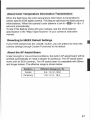
About Color Temperature Information Transmission
When the flash fires, the color temperature information is transmitted to
certain specific EOS digital camera . This feature optimizes the flash picture's
white balance. When the camera's color balance is set to aM> or <y >, it
wilt work automatically.
To see if this feature works with your camera, see the white balance
specification in the "Major Specifications' of your camera's instruction
manual .
Reverting to 580E
Default Settings
If your EpS camera has the CLEAR > button, you can press it to revert the
camera settings (except Custom Functions) to the default.
About the AF-Assist Beam
Under law-light or law-contrast conditions, the built-in AF-assist beam will be
emitted automatically to make it eaasier to autofocus. The AF-assist beam
works with al[ EDS cameras. The AF-assist beam is compatible with 28mm
and longer lenses . The effective range is shown below.
Position
Effective Range (m 1 ft)
Center
0 .6 - 10! 2 - 32 .8
Periphery
0 .6 . 5 1 2 - 16.4-
47
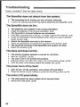
Troubleshooting
Hare a prahlem? See the table below.
The Speedli#e does not detach from the camera .
c: The mounting foots locking pin has not been retracted .
Loosen the locking ring all the way before detaching the Speedlite . (p.9)
The Speedliie does not fire,
~~ The batteries are installed in the wrong orientation.
~ Install the batteries in the correct orientation . (p.8)
j.
A
1
The Speedliie's infernal batteries are exhausted .
If the flash recycling time is 30 sec . or longer, replace the batteries. [p.8]
Install the Speedlite's internal batteries even when you use an external
power source. (p,8)
Attach the Speed lite securely to the tamers .
Attach the Speedlite's mounting foot securely to the camera . (p.9)
The electrical
contacts of the Speed lite and camera are dirty.
Clean the contacts . (p.9)
The slave unit does not fire .
0 The slave's wireless selector is not set to < SLAVE> .
o~ Set it to <SLAVED. (p .34)
a The slave unit is not positioned properly.
P,
Th e
Place the slave unit within the master units transmission range . [p .35]
Point the slave units sensor toward the master snit . [p .35]
power turns off by . itself .
,D After 90 sec. of idle operation, auto power off took effect .
a- Press the shutter button halfway or press the test firing button . (p .10)
The entire LCD panel blinks .
r The wide panel has been pulled out for bounce flash.
s Retract the wide panel. (p .20)
48
The flash range scale bars blink.
o
The flash head has been tilted down by 7° .
Change the bounce position . {p.19}
The periphery or bottom of the picture looks dark.
r
s
When you set the flash coverage manually, the setting was a higher
number than the lens focal length, resulting in a dark periphery.
Set the flash cove rage that is a lower number than the lens focal length o:
set it to auto zoom . (p .20)
If only the bottom of the picture looks dark, you were too close to the
subject .
r If the subject is closer than 2 m18 .6 It, tilt the flash head downward by 7' .
(P 19)
The flash exposure is underexposed or overexposed.
e There was a highly reflective object (glass window, etc.) in the picture .
P, Use FE lock. (p.16)
*
The subject has a very dark or light color.
0,
With high-speed sync, the effective flash range will be shorter. Make sure
the subject is within the effective flash range displayed [p .17]
0
Set flash exposure compensation . Fora dark subject, set a decreased flash
exposure . And far a bright subject, set an increased flash exposure . (p .14)
You used high-speed sync.
The picture is really blurred .
~
v
The shooting mode was set to ¢ AV >, and the scene was dark .
Use a tripod or set the shooting mode to <P> . (p .72)
49
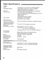
Major Specifications
" Type
Type :
Compatible cameras :
Guide No . :
Flash cQverage :
Flash duration :
Cola: temperature
info rmativn transmission :
" Exposure Control
ExpGsure Control Type :
Flash range
(with 50mm f11 .4, ISO 100]'
Flash exposure
cnrnpensaVon :
On -camera, E-TTL IvE~7TL,TTL au toflash SpredIiFe
Type-A E05 cameras [E-TTL iI1E~TTL autoffash],
Type- B EDS camaras [77L autoflash)
581190 (at 105mm focal length, 1$0 100 in meter-Meet)
24 - 105 mm (14 mm with wide panel)
" Auto room [flash coverage set automa[ically for lens snca!
length and image size]
" Manual zoom
" Flash head swing (bounce Flash)
Normal flash : 1 .2 ms or shorterQuick flash : 2 .3 ms or shorter
Flash color )omperature information Transmitted to camera
E-TTL III-TTUTTL autoHash, manual flash
Normal flash : D .5 - 3D m 11 .6 - 98 .4 ft
Quick flash : 0 .5 - 7 .5 m 11 .6 - 24 .fi ft {min .}
0 .5 ~ 21 m 1 1 .6 - 68 .9 it (max .)
Nigh-speed sync : U.5 ~ 15 m 11 .6-49 .2 ft (a111250 sec .)
FE lock :
High-sped sync :
Stroboscopic flash :
Manual, FEB : *3 stops in F13-stop increments
{Manual and FEB can tie Combined)
With .FE E ~ button or < *> button
Provided
Provided [t - 199 Hz]
confirmation :
Pilot lamp lights
Flash oxpasure
" Flash Recycling (with size-AA alkaline batteries]
Recycling time)
Flash-ready indicator :
Normal flash : 0 .1 to 6 sec . 1 Red pilot lamp lights
Quick flash : 0 .1 to 3 sec . i Green pilot lamp Ii g hts
- Wireless Flash
Transmission method :
Channels
Wireless options:
50
Optical pulse
4
OFF Master, and Slave
"Y
Tran%rnissiori range
(Apprax .)'
1
Controllable slave groups:
Flash ratio control :
Slave-ready indicator :
Modeling flash-
Outdoors, 5 2 . 15 m 139.4 - 49 .2 ft,
Indoors : 8 - 10 m : 26 .2 - 32.8 ft
vertical
Reception angle : -40` horizontal, t3Q3 (A, H, and C)
1 :8 - 1 :1 - 8:1 in 112-stop increments
AF-assist beam blinks
Fired with came ra'sdcpth-of-field pry/iew button
" CUStOttI Functions :
14 (2f1 settings)
-A F-Assist Beam
I .inkable AF points
Effective range [Approx .]-
" Power Source
Internal power
Battery life
{Apprnx . flash count}'
Battery life
[Aaprex. wlreless,ransmissicns] :
Power saviny:
External powcsr sources :
" Dimensions
1 .45 AF paints (28mm or longer focal length)
AF renter : O .G - 10 m/2-0 ~ 32 .8 it,
Periphery : 0 .6 . 5 m .120 - 18 .4 f[
Four sire-AA alkaline
Size-AA Ni-MM or lithium batteries also possible
100 - 700 flashes with size-AA alkaline batteries}
1500 transmissions [Master unit firing disabled, size-AA
alkaline batteries]
power off after 90 sec . or idle operation (60 min . if se[ as
slave)
Compact Battery Back CP-E3
(WxH x17) :
76x134x11Amm13 .0 x5 .3x4 .5in
" Weight :
375 g : 13.2 oz (Speedlite only, excluding batteries)
a AEI specifications are based on Canon's testing criteria .
s Product specifications and external appearance are subject to change without
notice .
51
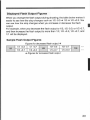
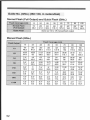
Guide No . (G No .) (ISO 100, in meters/feet)
Normal Flash (Full Output) and Quick Flash {GNo.}
Flash Coverage (mm)
Normal Flash
{Full output]
Quick Flash
14
24
2B
15~
119 .2
23:
91 .3
30.~
98 .4
3n 1 50
36 .
42+'
118 .1
137 .8
70
80
105
501
164
531
173 .9
581
10 .3
Same as 1!2 to T16 manual flash output
Manual Flash (GNo .)
Flash Qutput
~
24
Flash Coverage (mm)
151
49.2
10.81
34 .8
35
50
7D
80
281 ~
91 .9
301'
98 .4
36~
1 F 8.1
421
137 .8
501
164
19 .81
65
2121
69.8
25 .51
83.7
29 .71
97 .4
35 .4.'
116-1
53.1
173 .9
37.5 .'
123
1 58 :
90 .3
41 :
134 .5
114
7~5!
24 .6
151
49 .2
18'
59.1
211,
68 .9
251
82
26.51
86 .9
29'
95.1
118
5-3+
17 .4
10-6/
34 .8
12 .71
45 .7
14 .8 .E
48 .6
17 .71
58.1
18 .7/
61 .4
20 .5.E
67.3
1116
3 .8i
12 .5
14.E
45 .9
9 .91
32 .5
71
23
7 .51
24 .6
;31
29.5
10 .51
34 .4
12 .51
41
13 .3.E
43 .6
14 .5f
47.6
1132
2~7i
8.9
6 .4.+
21
7 .41
24 .3
8 .81
28 .9
9 .4:
30 .8
10 .31
33.8
1l64
1 .91
6.2
5.31
17 .4
3.81
12 .5
2 .7i
3 .9
4 .51
14.8
5 .31
17 .4
6 .31
20 .7
6 .E1
21 .7
3 .2,
10.5
3.7 :
12.1
4.4:
14 .4
4 .71
15 .4
7 .8~
2,1
5 .11
i6 .7
1IT
` 712
71128
52
14
1 .31
43
I
4 .9i
16.1
3 .51
11 .5
2 .51
8.2
28
105
Using a Type-B Camera
If you use the 580EX with a Type-S camera (TTL autoilash camera), note the
available features and restrictions below.
When a Type-B camera is used with the 580EX set to autoflash, <TTL.>
will be displayed on the Speedlite's LCa panel . {With a Type-A camera,
<ETTL> will be displayed .}
Features Available with All Type-13 Cameras
Configuration
Available Features
TTL autofiash
Flash exposure compensation
On-camera
shooting
FEB
Manual flash
Stroboscopic flash
Second-curtain sync
Wireless flash
Manual flash
Strnboscopic flash
Features not Available with Any Type-B Cameras
E-TTL III-TTL autoflash
FE lock
High-speed sync (FP flash)
Autoffash with wireless flash
Flesh ratio set with mufti-Speedlite wireless flash
"
"
*
A
"
Features Available with Some Type-B Cameras
. Eos s5ois2a : FEs
" Ep5 75p1850: FEB, stroboscopic flash, second-curtain sync,
wireless flash
" Eb5 700: FEB in modes except <Trr>
53
This device complies with Part 35 of the FCC Rules . Operation is subject to the
Tnllowing two conditions : (1 ) This device may not cause harmful interference,
and (2) this device must accept any interference received, including
inferference that may cause undesired operation .
Do not make any changes or modifications to the equipment unless
otherwise
specified in the instructions. If such changes or modifications should 6e made,
you could he required to stop operation of the equipment .
This equipment has been tested and found to comply with the limits (or a class
8 digital device, pursuant to part 15 of the FCC Rules. These limits are
designed to provide reasonable protection against harmful interference in a
residential installation . This equipment generates, uses and can radiate radio
frequency energy and, if not installed and used in accordance with the
instructions, may cause harmful interference to radio communications.
However, there is no guarantee that interference will not occur in a particular
installation . If this equipment does cause harmful interference to radio or
television reception, which can be determined by turning the equipment off and
on, the user is encouraged to try to correct the interference by one or more of
the following measures:
"
"
"
Reorient or relocate the receiving antennaIncrease the separation between thQ equipment and receiver.
Consult the dealer or an experienced radia'TV technician for help .
This digital apparatus does not exceed the Class 8 limits for radio noise
emissions from digital apparatus as set out in the interference-casing
equipment standard entitled "Digital Apparatus', ICES-003 of the Industry
Canada .
54
The apparatus shall not be exposed to dripping or splashing .
Batteries shall not be exposed to excessive heat such as sunshine, fire or the
like .
i
Dry galleries shall not be subjected to charging .
This mark indicates that the product complies with Australia's EMC
regulations .
55
This Instructions booklet is dated July 2004 . For information on the camera's
compatibility with system accessories marketed after this date, contact your
nearest Canon Service Center.