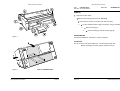
1
LA600 MultiPrinter
Field Service Manual
The information in this document is subject to change without notice and should not be construed as
a commitment by Digital Equipment Corporation. Digital Equipment Corporation assumes no
responsibility for any errors that may appear in this document.
Copyright © by Digital Equipment Corporation 1994.
All rights strictly reserved. Reproduction or issue to third parties in any form is not permitted without
written authorization from the publisher.
Pub. No. 5112 991 12932
November 1994
Order No.: ER-LA600-SV
LA600 Field Service Manual
LA600 Field Service Manual
4. Wearing Parts . . . . . . . . . . . . . . . . . . . . . . . . . . . . . . . . . . . . . . . . 4-1
Platen Assy A1 . . . . . . . . . . . . . . . . . . . . . . . . . . . . . . . . . . . . . . . . 4-2
ASF Pick-up Rollers . . . . . . . . . . . . . . . . . . . . . . . . . . . . . . . . . . . . . 4-6
Table of Contents
1. Safety Precautions . . . . . . . . . . . . . . . . . . . . . . . . . . . . . . . . . . . . . 1-1
5. List of Spares and Repairs . . . . . . . . . . . . . . . . . . . . . . . . . . . . . . 5-1
2. Preventive Actions for Keeping the Printer Running . . . . . . . . . . . 2-1
3. Procedures for Removal and Reassembly . . . . .
Housing . . . . . . . . . . . . . . . . . . . . . . . . . . . . . . .
Printer Engine LA600 . . . . . . . . . . . . . . . . . . . . . .
PSU-40A Assy . . . . . . . . . . . . . . . . . . . . . . . . . .
DEV-40 LA600 Assy . . . . . . . . . . . . . . . . . . . . . .
CU-40 LA600 Assy . . . . . . . . . . . . . . . . . . . . . . .
EEPROM CU-40-00 . . . . . . . . . . . . . . . . . . . . . . .
Operator Panel . . . . . . . . . . . . . . . . . . . . . . . . . .
Power ON/OFF Switch Assy . . . . . . . . . . . . . . . . .
Cable Print Head Assy . . . . . . . . . . . . . . . . . . . . .
Encoder Strip Assy . . . . . . . . . . . . . . . . . . . . . . .
Kit Lubrication Felt . . . . . . . . . . . . . . . . . . . . . . . .
Print Head H-Encoder 40A . . . . . . . . . . . . . . . . . .
Horizontal Motor 40A . . . . . . . . . . . . . . . . . . . . . .
Carriage 40A Assy . . . . . . . . . . . . . . . . . . . . . . . .
Protection Shield . . . . . . . . . . . . . . . . . . . . . . . . .
Ribbon Gear Assy . . . . . . . . . . . . . . . . . . . . . . . .
Rep. Kit Ribbon Gear . . . . . . . . . . . . . . . . . . . . . .
Stepping Motor 7.5 DEG (Platen gap control) . . . .
Stepping Motor 1.8 DEG (Vertical paper transport)
Tractor Gear 40A . . . . . . . . . . . . . . . . . . . . . . . . .
Stacker Elements 40B Assy . . . . . . . . . . . . . . . . .
Print Head LA600 . . . . . . . . . . . . . . . . . . . . . . . .
Paper Run/In Detector Assy . . . . . . . . . . . . . . . . .
Kit Pressure Roll FF1 . . . . . . . . . . . . . . . . . . . . . .
Kit Vertical Transport A40 . . . . . . . . . . . . . . . . . .
Minipitch Belt Stepper . . . . . . . . . . . . . . . . . . . . .
Minipitch Belt Form Feed . . . . . . . . . . . . . . . . . . .
Kit Belt Pulley 40A . . . . . . . . . . . . . . . . . . . . . . . .
Kit Cont. Forms Exit 40A . . . . . . . . . . . . . . . . . . .
Kit Tractor 40A . . . . . . . . . . . . . . . . . . . . . . . . . .
Kit Belt Tension 40A . . . . . . . . . . . . . . . . . . . . . .
Kit ASF Levers . . . . . . . . . . . . . . . . . . . . . . . . . .
Kit Torsion Spring D-Axis . . . . . . . . . . . . . . . . . . .
Kit Screws and Springs . . . . . . . . . . . . . . . . . . . .
Digital Equipment Corporation
.
.
.
.
.
.
.
.
.
.
.
.
.
.
.
.
.
.
.
.
.
.
.
.
.
.
.
.
.
.
.
.
.
.
.
.
.
.
.
.
.
.
.
.
.
.
.
.
.
.
.
.
.
.
.
.
.
.
.
.
.
.
.
.
.
.
.
.
.
.
.
.
.
.
.
.
.
.
.
.
.
.
.
.
.
.
.
.
.
.
.
.
.
.
.
.
.
.
.
.
.
.
.
.
.
.
.
.
.
.
.
.
.
.
.
.
.
.
.
.
.
.
.
.
.
.
.
.
.
.
.
.
.
.
.
.
.
.
.
.
.
.
.
.
.
.
.
.
.
.
.
.
.
.
.
.
.
.
.
.
.
.
.
.
.
.
.
.
.
.
.
.
.
.
.
.
.
.
.
.
.
.
.
.
.
.
.
.
.
.
.
.
.
.
.
.
.
.
.
.
.
.
.
.
.
.
.
.
.
.
.
.
.
.
.
.
.
.
.
.
.
.
.
.
.
.
.
.
.
.
.
.
.
.
.
.
.
.
.
.
.
.
.
.
.
.
.
.
.
.
.
.
.
.
.
.
.
.
.
.
.
.
.
.
.
.
.
.
.
.
.
.
.
.
.
.
.
.
.
.
.
.
.
.
.
.
.
.
.
.
.
.
.
.
.
.
.
.
.
.
.
.
.
.
.
.
.
.
.
.
.
.
.
.
.
.
.
.
.
.
.
.
.
.
.
.
.
.
.
.
.
.
.
.
.
.
.
.
.
.
.
.
.
.
.
.
.
.
.
.
.
.
.
.
.
.
.
.
.
.
.
.
.
.
.
.
.
.
.
.
.
.
.
.
.
.
.
.
.
.
.
.
.
.
.
.
.
.
.
.
.
.
.
.
.
.
.
.
.
.
.
.
.
.
.
.
.
.
.
.
.
.
.
.
.
.
.
.
.
.
.
.
.
.
.
.
.
.
.
.
.
.
.
.
.
.
.
.
.
.
.
.
.
.
.
.
.
.
.
.
.
.
.
.
.
.
.
.
.
.
3-1
3-2
3-4
3-6
3-8
3-10
3-12
3-14
3-16
3-18
3-20
3-22
3-24
3-26
3-28
3-30
3-32
3-34
3-36
3-38
3-40
3-42
3-44
3-48
3-50
3-52
3-52
3-52
3-54
3-56
3-58
3-60
3-62
3-64
3-66
Page 0-1
Page 0-2
Digital Equipment Corporation
LA600 Field Service Manual
1.
Safety Precautions
1.
Some of the maintenance procedures described in this section
require that the printers top housing is removed. This exposes
the internal working parts of the printer. During operating some
of these parts are potentially dangerous.
2.
All replacement and cleaning procedures should be performed
with the printer switched OFF and the mains connector
disconnected.
3.
Only recommended parts should be used to replace defective
parts. Details of field exchangeable parts, including part number
and service number are listed in Chapter 5 ’Spares and Repairs’.
4.
Switch the printer OFF while connecting or disconnecting a
Personality Module, a Memory Card or a Colour Option.
5.
Never print over the edges of paper or beyond the perforations of
fanfold paper, otherwise the print head can be damaged.
6.
Never attempt to print with no paper loaded or no ink ribbon
installed in the printer
7.
Put the printer in the STOP mode immediately a paper jam
occurs, using the START/STOP key at the Operator Panel.
Digital Equipment Corporation
Page 1-1
Page 1-2
Digital Equipment Corporation
LA600 Field Service Manual
2.
Preventive Actions for Keeping the Printer Running
The following points should be additionally checked on a service call.
Item
Platen
*)
Paper input transport
rollers
ASF
*)
*)
Problem
Remedial Action
Paper feeding problems
Remove platen and clean
surface thoroughly using
platen cleaner S/CP 09.
Paper feeding problems
Disconnect mains cable,
remove the ribbon, and
remove housing (see
chapter 3, Part: Housing).
Also remove the paper guide
secured with two green
screws. Clean all transport
rollers using platen cleaner
S/CP 09.
Paper insertion problems
Remove ASF cassette.
Clean pick-up rollers using
platen cleaner S/CP 09, and
check the paper handling of
the ASF cassette using a
few sheets of paper which
have to be transported
properly by manually rotating
the pick-up wheel of the
ASF-cassette.
Refer to Chapter 4 to check a necessary exchange of platen or pick-up rollers.
Digital Equipment Corporation
Page 2-1
Page 2-2
Digital Equipment Corporation
LA600 Field Service Manual
3.
LA600 Field Service Manual
Procedures for Removal and Reassembly
Part:
Housing
Part No: 5112 292 38200
DEC P/N:
FD-W03RF-01
This chapter describes the removal procedures which are necessary for proper
handling of the spare parts and subunits of the printer.
REMOVAL
Note:
Disconnect mains cable
All removal procedures consists of several steps indicated with a:
to show preparation and
⇒
to indicate the main removal steps.
Remove the manual front insertion (A)
⇒
Remove the front cover (B) resp. the ASF cassette(s) out of the
mounting slots (C)
⇒
Swing cover (D) to its nearly upright position and remove it
⇒
a) Remove the cover (E) by releasing the cover snap locks
(F) with a flat bladed screwdriver
b) To remove the cover (E) grasp it by the sides, raise the
front slightly, push the cover back until the metal snaps
are out of the slots at the rear of the printer and then lift
the cover
REASSEMBLING
Execute the REMOVAL procedure in reverse sequence
Digital Equipment Corporation
Page 3-1
Page 3-2
Digital Equipment Corporation
LA600 Field Service Manual
LA600 Field Service Manual
Part:
Printer Engine LA600
Part No: 5112 292 62901
DEC P/N:
29 31790-01.A01
REMOVAL
Set the printer into "LOCAL MODE"
Disconnect the system interface cable
Remove the ribbon cartridge
Switch the printer off and disconnect the mains cable
⇒
Remove all encasing parts
⇒
Remove the personality module (A)
⇒
Remove the plastic insert of the memory card
interface (B)
⇒
Loosen screw (C)
⇒
Remove screws (D)
⇒
Disconnect the Device Electronic (E)
⇒
Disconnect the Control Unit (F)
⇒
Loosen the fixation screws of the power on
switch and remove it (G)
⇒
Swivel the printer as shown in figure 2.
Note:
For protection of the operator panel please use a part of the
packaging material of the new printer engine as support.
⇒
⇒
Shift the entire Electronic Subassembly
to the left. (1)
Swivel it in the direction towards you
and remove it from the printer
engine. (2)
REASSEMBLING
Unpack the new printer engine
Execute the REMOVAL procedure with the new printer engine in reverse
direction.
⇒
Change the print head from the "old" printer engine into the "new"
one.
⇒
Perform an AGC Adjust procedure
⇒
Adjust the parameter "Paper In Adj." to the value indicated on
the field service instruction attached to the new printer engine.
⇒
Perform "PRINT TEST 3" and check for proper operation of
the printer.
Note:
Digital Equipment Corporation
Page 3-3
Page 3-4
Take a note of the value of the page counter (PGCNT) on the
FRU-label of the new printer engine.
Digital Equipment Corporation
LA600 Field Service Manual
LA600 Field Service Manual
Part:
PSU-40A Assy
Part No: 5112 292 38110
DEC P/N:
FD-W02BY-01
REMOVAL
Disconnect mains cable
Remove all encasing parts (see Part: Housing)
Loosen the two screws (A) securing the PSU-40A assy
⇒
Lift the complete Power Supply Unit (PSU), using a screwdriver
⇒
Disconnect plug (C)
⇒
Remove clamp (D) and disconnect plug (B)
REASSEMBLING
Execute the REMOVAL procedure in reverse sequence
Figure 1
ATTENTION:
Do not touch the PSU board within min. 2 minutes after power OFF
Before exchanging the PSU, please check the fuse (F)
Figure 2
Digital Equipment Corporation
Value of PAPER-IN ADJ.:
Page 3-5
Page 3-6
Digital Equipment Corporation
LA600 Field Service Manual
LA600 Field Service Manual
Part:
DEV-40 LA600 Assy
Part No: 5112 292 62921
DEC P/N:
29-31791-01 A01
REMOVAL
Disconnect mains cable
Remove all encasing parts (see Part: Housing)
⇒
Loosen the two screws (A) and remove screw (B)
⇒
Remove the DEV-40 LA600 Assy
a) while removing, DEV-40 LA600 assy (K) is automatically
disconnected from CU-40 LA600 assy (C)
b) disconnect all plug connections from the DEV-board:
- plug (D)
- plug (E)
- plug (F)
Reassembly
Execute the REMOVAL procedure in reverse sequence
Attention:
Digital Equipment Corporation
Page 3-7
Page 3-8
Wire (L) has to be fastened by screw (B) as shown in Detail Z
Digital Equipment Corporation
LA600 Field Service Manual
LA600 Field Service Manual
Part:
CU-40 LA600 Assy
Part No: 5112 292 62991
DEC P/N:
29-31792-01. A01
REMOVAL
Disconnect mains cable
Remove all encasing parts (see Part: Housing)
Remove DEV-40 LA600 Assy (see Part: DEV-40 LA600 Assy)
⇒
Remove if plugged in memory card (A)
⇒
Remove the Personality Module after loosing the two
lockscrews (B)
⇒
Disconnect plug (C) from CU-40 LA600 Assy and
remove CU-40 LA600 Assy
⇒
Note:
Remove the EEPROM CU-40-00 (D) and plug it
into the new CU-40 LA600 assy.
Pay attention, that EEPROM (D) is stuffed correct
position (pin marker (E))
Reassembly
Execute the REMOVAL procedure in reverse sequence
Note:
Digital Equipment Corporation
Page 3-9
Start the function ’Print Out’ and check ’Current Settings’
Page 3-10
Digital Equipment Corporation
LA600 Field Service Manual
LA600 Field Service Manual
Part:
EEPROM CU-40-00
Part No: 5112 208 07590
DEC P/N:
29-31802-01. A01
REMOVAL
Disconnect mains cable
Remove all encasing parts (see Part: Housing)
Remove DEV-40 LA600 Assy (see Part: DEV-40 LA600 Assy)
Remove CU-40 LA600 Assy (see Part: CU-40 LA600 Assy)
⇒
Note:
Exchange the EEPROM CU-40-00 (D)
Pay attention, that EEPROM (D) is stuffed correctly
position (pin marker (E))
Reassembly
Execute the REMOVAL procedure in reverse sequence
Note:
Digital Equipment Corporation
Page 3-11
Start the function ’Print Out’ and check ’Current Settings’
Page 3-12
Digital Equipment Corporation
LA600 Field Service Manual
LA600 Field Service Manual
Part:
Operator Panel
Part No: 5112 292 38150
DEC P/N:
FD-W00CU-01
REMOVAL
Disconnect mains cable
Remove all encasing parts (see Part: Housing)
⇒
Disconnect Operating Panel cable (A)
⇒
Loosen the screw (B) located at the bottom of the Operating
Panel
⇒
Remove the Operator Panel Assy
REASSEMBLING
Execute the Removal procedure in reverse sequence
Note:
Digital Equipment Corporation
Page 3-13
Remove the protection foil (C) from the Operator Panel installed
before mounting the housing
Page 3-14
Digital Equipment Corporation
LA600 Field Service Manual
LA600 Field Service Manual
Part:
Power ON/OFF Switch Assy
Part No: 5112 292 38820
DEC P/N:
FD-W02B3-01
REMOVAL
Disconnect mains cable
Remove all encasing parts (see Part: Housing)
Remove PSU-40A Assy (see Part: PSU-40A Assy)
⇒
Loosen the two screws (A)
⇒
Remove the power ON/OFF Switch Assy
REASSEMBLING
Execute the REMOVAL procedure in reverse sequence.
Digital Equipment Corporation
Page 3-15
Page 3-16
Digital Equipment Corporation
LA600 Field Service Manual
LA600 Field Service Manual
Part:
Cable Print Head Assy
Part No: 5112 292 38800
DEC P/N:
FD-W02Y2-01
REMOVAL
Disconnect mains cable
Remove all encasing parts (see Part: Housing)
⇒
a) Disconnect print head cable from the print head
b) Remove the noise reduction foam (A) from the cable channel
c) Clip the plastic support (B) from the print head carriage, by
first releasing clamps (C)
d) Disconnect the wire-to-wire connection (D) of the H-Encoder
Assy
e) Disconnect the colour option, if installed, incl.connector
f) Disconnect cable (E) from the interface connection board
g) Disconnect the print head cable from DEV-40 LA600 Assy
h) Remove the two plastic clips (F)
i) Remove the print head cable
REASSEMBLING
Execute the REMOVAL procedure in reverse sequence
Digital Equipment Corporation
Page 3-17
Page 3-18
Digital Equipment Corporation
LA600 Field Service Manual
LA600 Field Service Manual
Part:
Encoder Strip Assy
Part No: 5112 292 37970
DEC P/N:
FD-W0417-01
REMOVAL
Disconnect mains cable
Remove all encasing parts (see Part: Housing)
⇒
⇒
Remove the two screws (A) (Detail Y)
Remove the encoder strip 40A Assy (B)
REASSEMBLING
a) Move the carriage to the centre position
b) Execute the REMOVAL procedure in reverse sequence
Caution: Pay attention, that the Encoder Strip Assy is mounted in the
correct position by (Detail Z) and observe that the strip is
slipping under the first two steel noses visible from the
front side of the printer.
Digital Equipment Corporation
Page 3-19
Page 3-20
Digital Equipment Corporation
LA600 Field Service Manual
LA600 Field Service Manual
Part:
Kit Lubrication Felt
Part No: 5112 270 04541
DEC P/N:
29-31804-01. A01
REMOVAL
Disconnect mains cable
Remove all encasing parts (see Part: Housing)
Remove Encoder Strip Assy (see Part: Encoder Strip Assy)
Remove operator panel, but leave the interface cable connected
(see Part: Operator Panel)
⇒
a) Remove the two springs (C)
b) Remove the upper guide rail (D)
⇒
Exchange the lubrication felt (E). Insert the new felt with
flatten ear towards the operator panel
REASSEMBLING
Execute the REMOVAL procedure in reverse sequence
Caution: Pay attention that the encoder strip Assy is mounted in a
correct position (Detail Z) and observe that the strip is
slipping under the first two steel noses seen from the front
side of the printer
Digital Equipment Corporation
Page 3-21
Page 3-22
Digital Equipment Corporation
LA600 Field Service Manual
LA600 Field Service Manual
Part:
Print Head H-Encoder 40A
Part No: 5112 292 43100
DEC P/N:
FD-W0290-01
REMOVAL
Disconnect mains cable
Remove all encasing parts (see Part: Housing)
Remove encoder strip Assy (see Part: Encoder Strip Assy)
Remove the noise reduction foam (see Part: Cable Print Head
Assy)
⇒
Remove the upper screws (A)
⇒
Loosen the two screws (B) and remove the mounting
plate and the right side cover plate
⇒
Move the Carriage Assy to the cutout (D)
⇒
Remove the two screws (E) from the Carriage
Assy
⇒
Disconnect the print head cable from the head
⇒
Clip the plastic support (F) from the carriage
Assy and disconnect the wire-to-wire
connector (G)
H-Encoder/print head cable
⇒
Remove the cable clamp from the carriage
⇒
Remove the print head H-Encoder Assy
REASSEMBLING
Execute the REMOVAL procedure in reverse sequence
Note:
Digital Equipment Corporation
Page 3-23
Pay attention that the logic cable is fixed correctly by clamp (H)
Page 3-24
Digital Equipment Corporation
LA600 Field Service Manual
LA600 Field Service Manual
Part:
Horizontal Motor 40A
Part No: 5112 292 37910
DEC P/N:
FD-W0396-01
REMOVAL
Disconnect mains cable
Remove all encasing parts (see Part: Housing)
Remove DEV-40 Assy (see Part: DEV-40 LA600 Assy)
⇒
a) Disengage the drive belt (A) from the drive wheel of the
horizontal motor by pressing the belt tension element (B),
which is located at the left side of the engine, upwards
b) Pull off the belt from the wheel
c) Disconnect the two pin motor cables (C) from the motors
connector (D)
d) Remove the two cables from the motor fixing plate (E)
e) Remove the horizontal motor Assy
REASSEMBLING
Execute the REMOVAL procedure in reverse sequence
Note:
Digital Equipment Corporation
Page 3-25
Page 3-26
Pay attention that the cable installation is correct (Detail Y)
Digital Equipment Corporation
LA600 Field Service Manual
LA600 Field Service Manual
Part:
Carriage 40A Assy
Part No: 5112 292 40940
DEC P/N:
FD-W04JL-01
REMOVAL
Disconnect mains cable
Remove all encasing parts (see Part: Housing)
Remove DEV-40 Assy (see Part: DEV-40 LA600 Assy)
Remove the encoder strip Assy (see Part Encoder Strip Assy)
Remove operator panel, but leave the interface cable connected
(see Part: Operator Panel)
Remove the cable print head Assy from the print head carriage
(see Part: Cable Print Head Assy)
⇒
a) Remove the two guide rail springs (A)
b) Remove the upper guide rail (B)
c) Pull the lever (C) from the lock pin and remove the
lever
d) Release spring (F) and remove lever (G) inclusive
springs
e) Remove the screw (H). Push the shaft (I) including the
plastic segment (J) out towards the right hand side of
the chassis
Note:
the PCC lever (J) can not be removed
f) Slide the carriage out of the guide rail
REASSEMBLING
Execute the REMOVAL procedure in reverse sequence
!
Digital Equipment Corporation
Page 3-27
Note:
Page 3-28
Engage the plastic segment such, of the guide rail (J) that the
marker (K) aligns with the marker (L) on the PCC gear (Detail
"Z").
Digital Equipment Corporation
LA600 Field Service Manual
LA600 Field Service Manual
Part:
Protection Shield
Part No: 5112 292 38390
DEC P/N:
FD-W041W-01
REMOVAL
Disconnect mains cable
Open top cover
Remove Ink Ribbon
Remove Platen
⇒
Dismount protection shield (B) by loosening the two screws (A).
This can easily be done by inserting of a torx screwdriver of at
minimum 110 mm length through the holes (C) in the bottom
plate and the platen channel
REASSEMBLING
Execute the REMOVAL procedure in reverse sequence
Digital Equipment Corporation
Page 3-29
Page 3-30
Digital Equipment Corporation
LA600 Field Service Manual
LA600 Field Service Manual
Part:
Ribbon Gear 40B Assy
Part No: 5112 292 63840
DEC P/N:
FD-W045W-01
REMOVAL
Disconnect mains cable
Remove all encasing parts (see Part: Housing)
Remove DEV-40 Assy (see Part: DEV-40 LA600 Assy)
⇒
⇒
Locate the Ribbon Gear 40B Assy (A)
a) Loosen the cable (F) from the cable guide
b) Loosen the spring (B), remove lever (C) from (D)
c) Disconnect the 2 pin motor cable from the motor
connector (F)
d) Push the lock tab (E) and remove the Ribbon Gear 40B Assy
REASSEMBLING
Execute the REMOVAL procedure in reverse sequence
Note:
Digital Equipment Corporation
Page 3-31
Page 3-32
Pay attention that the cable installation is correct (Detail Y)
Digital Equipment Corporation
LA600 Field Service Manual
LA600 Field Service Manual
Part:
Rep. Kit Ribbon Gear
Part No: 5112 292 41091
DEC P/N:
t. b. f.
REMOVAL
Disconnect mains cable
Remove all encasing parts (see Part: Housing)
Remove DEV-40A Assy (see Part: DEV-40 LA600 Assy)
⇒
⇒
Locate the Ribbon Gear 40B Assy (A)
a)
b)
c)
d)
Loosen the cable (F) from the cable guide
Loosen the spring (B), remove lever (C) from (D)
Push the lock tab (E) and remove the ribbon gear 40A Assy
Open the gear box cover by loosening the 3 clips. Insert a
screwdriver in (G) for clip 1)
e) Remove the 2 gear wheels (I)
f) Replace the o-ring (H) by the spare part
g) Replace the 2 gear wheels (I) by the spare part
REASSEMBLING
Execute the REMOVAL procedure in reverse sequence
Digital Equipment Corporation
Page 3-33
Page 3-34
Digital Equipment Corporation
LA600 Field Service Manual
LA600 Field Service Manual
Part:
Stepping Motor 7.5 DEG
(Platen gap control)
Part No: 5112 209 24460
DEC P/N:
FD-W0394-01
REMOVAL
Disconnect mains cable
Remove all encasing parts (see Part: Housing)
Remove DEV-40A Assy (see Part: DEV-40 LA600 Assy)
⇒
Disconnect the four pin motor cables from the motors plug
⇒
Remove the two screws (B) fixation of the stepper motor
Warning: Do not loosen the screw (A). This is a factory
adjustment; field adjustment is impossible
⇒
Remove the stepper motor
REASSEMBLING
Execute the REMOVAL procedure in reverse sequence
Note:
Digital Equipment Corporation
Page 3-35
Make sure that the cable installation is correct (Detail Y)
Page 3-36
Digital Equipment Corporation
LA600 Field Service Manual
LA600 Field Service Manual
Part:
Stepping Motor 1.8 DEG
(Vertical Paper Transport)
Part No: 5112 292 62411
DEC P/N:
29-31798-01. A01
REMOVAL
Disconnect mains cable
Remove all encasing parts (see Part: Housing)
Remove DEV-40 Assy (see Part: DEV-40 LA600 Assy)
⇒
Remove the motor cable guide from the DEV-40 Assy
⇒
⇒
Remove the four pin motor cable (A) from the cable guide
a) Remove the two screws (B), of the vertical drive motor
b) Turn the motor anti-clockwise and remove it from the
mounting clamp
c) Disengage the drive belt (C) from the drive pinion
d) Remove the motor (D)
REASSEMBLING
Execute the REMOVAL procedure in reverse sequence
Note:
Digital Equipment Corporation
Page 3-37
Pay attention that the cable installation is correct (Detail Y)
Page 3-38
Digital Equipment Corporation
LA600 Field Service Manual
LA600 Field Service Manual
Part:
Tractor Gear 40A
Part No: 5112 292 38030
DEC P/N:
FD-W045N-01
REMOVAL
Disconnect mains cable
Remove all encasing parts (see Part: Housing)
Remove DEV-40 Assy (see Part: DEV-40 LA600 Assy)
⇒
a) The paper path for output must be set to tractor. By moving
the carriage to the uppermost right position the paper path
will be changed (an audible "click")
b) The axle (A) must be turned to the position as shown in
detail by turning on the minipitch belt (C) in clockwise
direction
c) Remove all cables from the cable guide
d) Remove the three screws (E) and remove the tractor gear
40A Assy
REASSEMBLING
Execute the REMOVAL procedure in reverse sequence
Note:
- Before the new assy. can be mounted, turn the gearwheel (F)
in such a way that the bold (G) reaches the uppermost
position
- Observe that the cable installation is correct (Detail Y)
Digital Equipment Corporation
Page 3-39
Page 3-40
Digital Equipment Corporation
LA600 Field Service Manual
LA600 Field Service Manual
Part:
Stacker Elements 40B Assy
Part No: 5112 292 40990
DEC P/N:
FD-W04KK-01
REMOVAL
Disconnect mains cable
Remove all encasing parts (see Part: Housing)
Remove DEV-40 Assy (see Part: DEV-40 LA600 Assy)
⇒
Loosen the two screws (A) securing the Power ON/OFF switch
and put it away
⇒
⇒
Remove the two screws (C) which secure the stacker
elements plate
a) Remove the circlip (D) which secures the bearing (E)
b) Slide the bearing (E) to the left and remove the Stacker
Elements Assy
REASSEMBLING
Execute the REMOVAL procedure in reverse sequence
Digital Equipment Corporation
Page 3-41
Page 3-42
Digital Equipment Corporation
LA600 Field Service Manual
LA600 Field Service Manual
Part:
Print Head LA600
Part No: 5112 292 62761
DEC P/N:
29-31807-01. A01
Removal of the print head (5)
Caution: print head may be very hot immediately after printing!
Lift and remove the output stacker (1)
Switch the printer ON, lift and remove the top cover (2), switch the
printer OFF
Remove the ribbon cassette (3)
⇒
Disconnect the print head cable (4)
⇒
Using the supplied tool (7), loosen the two captive screws (6),
retaining the print head (5)
⇒
Note:
Remove the print head (5)
Please record on the tag accompanied to the print head replaced:
- PGCNT (Number of pages printed can be obtained from print
out of ’PRINT TEST 3’, parameter ’PGCNT’ (see
Installation and User Guide, chapter 8))
- Printer Serial Number
each time a print head is replaced!
Digital Equipment Corporation
Page 3-43
Page 3-44
Digital Equipment Corporation
LA600 Field Service Manual
LA600 Field Service Manual
Installing the new print head (5)
Ensure that the printer is switched OFF. For print head installation, the carriage
should be aligned with the cut-out on the paper guide plate (green insert).
(Same position as for Removal procedure).
⇒
1
3
4
Hold the print head (5) in its mounting position and press it against
its stop in direction of the platen. The two noses (9) of the
adjustment guide (8) support this procedure.
2
Note:
⇒
Older versions of the print head are mounted with clamps instead
of the adjustment guide (8)
Now tightening the two captive screws (6) (first left, then right).
⇒
5
Reconnect the print head cable (4) and fasten it with the
enclosed spring on the on the top of the print head.
Switch printer ON and insert the ink ribbon cassette
(3).
7
Refit the top cover (2) and the output stacker (1).
PM AGC: (s. Installation and User Guide, Chapter 3)
Run the MENU-function AGC ADJUST with ribbon cassette installed but
without paper loaded
6
Note:
Please record on the tag accompanied to the print head replaced:
- PGCNT (Number of pages printed can be obtained from print
out of ’PRINT TEST 3’, parameter ’PGCNT’ (see
Installation and User Guide, chapter 8))
- Printer Serial Number
each time a print head is replaced!
Digital Equipment Corporation
Page 3-45
Page 3-46
Digital Equipment Corporation
LA600 Field Service Manual
LA600 Field Service Manual
Part:
Paper Run/In Detector Assy
Part No: 5112 292 38050
1
3
4
DEC P/N:
FD-W04JJ-01
REMOVAL
2
Disconnect mains cable
Remove all encasing parts (see Part: Housing)
⇒
⇒
5
Remove circlip (A) and bearing (B). The axle falls down
a) Remove the Detector
b) Disconnect the cable (E)
REASSEMBLING
Execute the REMOVAL procedure in reverse sequence
7
6
Digital Equipment Corporation
Page 3-47
Page 3-48
Digital Equipment Corporation
LA600 Field Service Manual
LA600 Field Service Manual
Part:
Kit Pressure Roll FF1
Part No: 5112 292 41080
DEC P/N:
29-31801-01. A01
REMOVAL
Disconnect mains cable
Remove all encasing parts (see Part: Housing)
Remove the encoder strip Assy (see Part: Encoder Strip Assy)
⇒
Remove the upper screws (A)
⇒
Remove the foam under neath of the printhead cable hooks
⇒
Loosen the two screws (B) and remove the metal sheet coner
⇒
Snap out the 4 springs (C) using a knife
⇒
Remove the pressure roller
⇒
Grease the bearings of the pressure roller with Molykote
DX or a similar type of grease
⇒
Grease the arms of the new springs at the
positions which are in contact with the FF1 roll with
Molykote DX or a similar type of grease
⇒
Insert the new springs by snap in
REASSEMBLING
Execute the REMOVAL procedure in reverse sequence
Digital Equipment Corporation
Page 3-49
Page 3-50
Digital Equipment Corporation
LA600 Field Service Manual
LA600 Field Service Manual
Part:
Kit Vertical Transport 40A
Part No: 5112 292 38450
DEC P/N:
FD-W02M6-01
Part:
Minipitch Belt Stepper
Part No: 5112 200 08780
DEC P/N:
FD-W032Y-01
Part:
Minipitch Belt Form Feed
Part No: 5112 200 08790
DEC P/N:
FD-W0330-01
REMOVAL
Disconnect mains cable
Remove all encasing parts (see Part: Housing)
Remove DEV-40 Assy (see Part: DEV-40 LA600 Assy)
⇒
a)
b)
c)
d)
Locate the right side of the form feed shaft for exchanging
Remove both minipitch belts (B)
Pull the belt pulley (C) from the wheel shaft for exchanging
If the upper form feed shaft has to be exchanged remove
the bearing (E)
e) Remove circlip (F) and bearing (G) on the left side from the
wheel shaft for exchanging
f) Removing the bearings causes the wheel shaft to fall down
into the larger holes, for removal slide the wheel shaft to the
left side
REASSEMBLING
Execute the REMOVAL procedure in reverse sequence
Digital Equipment Corporation
Page 3-51
Page 3-52
Digital Equipment Corporation
LA600 Field Service Manual
LA600 Field Service Manual
Part:
Kit Belt Pulley 40A
Part No: 5112 292 49210
DEC P/N:
FD-W05RM-01
REMOVAL
Disconnect mains cable
Remove all encasing parts (see Part: Housing)
Remove DEV-40 Assy (see Part: DEV-40 LA600 Assy)
⇒
a) Locate the right side of the form feed shaft for exchanging
b) Remove both minipitch belts (B)
c) Pull the belt pulley (C) from the wheel shaft to be exchanged
REASSEMBLING
Execute the REMOVAL procedure in reverse sequence
Digital Equipment Corporation
Page 3-53
Page 3-54
Digital Equipment Corporation
LA600 Field Service Manual
LA600 Field Service Manual
Part:
Kit Cont. Form Exit 40A
Part No: 5112 292 38460
DEC P/N:
FD-W02M7-01
REMOVAL
Disconnect mains cable
Remove all encasing parts (see Part: Housing)
Remove DEV-40 Assy (see Part: DEV-40 LA600 Assy)
Remove stacker elements Assy (see Part: Stacker Elements 40B
Assy)
⇒
a) Locate the gearwheel (B), remove the circlip (C) and the
washer (D), remove gearwheel (B) and bearing (A) from
the wheel shaft
b) Remove circlip (E) from the wheel shaft and move it to the
left. Remove the shaft
c) Prepare the left hand side bearing of the pressure roll (H),
such that it can be removed
d) Remove the pressure roll the Assy. out
REASSEMBLING
Execute the REMOVAL procedure in reverse sequence
Digital Equipment Corporation
Page 3-55
Page 3-56
Digital Equipment Corporation
LA600 Field Service Manual
LA600 Field Service Manual
Part:
Kit Tractor 40A
Part No: 5112 292 38470
DEC P/N:
FD-W02M8-01
REMOVAL
Disconnect mains cable
Remove all encasing parts (see Part: Housing)
Snap out the paper supports (C)
⇒
a) Locate the bearing (A) and (B) on the left side of the printer
b) Press the two locking tabs on the bearing (A) and remove it
c) Press the three locking tabs on the bearing (B) and remove
it
d) For removal slide the entire tractor kit first to the left and
then remove it by sliding out to the right.
REASSEMBLING
Execute the REMOVAL procedure in reverse sequence
Note: Pay attention that the mounting position of the left tractor is
between the stoppers (D). When you insert the square shaft, the
white dot on the left and right hand tractor must have the same
position to ensure synchronous running of the belts
Digital Equipment Corporation
Page 3-57
Page 3-58
Digital Equipment Corporation
LA600 Field Service Manual
LA600 Field Service Manual
Part:
Kit Belt Tension 40A
Part No: 5112 292 38480
DEC P/N:
FD-W02M5-01
REMOVAL
Disconnect mains cable
Remove all encasing parts (see Part: Housing)
Remove the print head
⇒
a) Disengage the drive belt (A) from the drive wheel horizontal
motor by pressing the belt tension elements on pos. (B)
b) Slide the drive belt out of the drive wheel
c) Remove the drive belt roller bearing (C) from its mounting
bracket
d) Remove the screw (D) and disengage the wedge (E) from the
print head carriage
REASSEMBLING
Execute the REMOVAL procedure in reverse sequence
Digital Equipment Corporation
Page 3-59
Page 3-60
Digital Equipment Corporation
LA600 Field Service Manual
LA600 Field Service Manual
Part:
Kit ASF Lever
Part No: 5112 292 22480
DEC P/N:
FD-W04B7-01
REMOVAL
⇒
Remove the AFS-Cassette from the printer and remove any paper
loaded, and the paper support (if mounted).
⇒
Remove the side cover of the ASF Cassette by releasing of four
snaplocks (No. 1 - 4 in figure 1). Use a flat screw driver to do so
and keep the sequence of figure 1.
⇒
Remove the circlip (No. 4 in figure 2) of the lever shaft.
⇒
Push the bar against the opposite side to release the mounted
levers. Snap the levers of the bar using a screw driver.
REASSEMBLING
⇒
a) Assemble the three levers together (figure 3). Lever 2
(upper paper release) onto lever 1 (paper pressure lever),
and lever (lower paper release) onto lever 2. Observe that
the little plug of lever 2 is fitted in the hole provided in
lever 3.
b) Snap the assembled levers into the ASF Cassette. Be
careful to mount the snaplock of the paper pressure lever
(lever 1) in one of the holes provided in the sidewall of the
cassette (figure 4).
c) Push the bar back into the levers and adjust the flat side of
the bar accordingly.
d) Secure the levers using the circlip and snap the flat side of
the ASF Cassette in place again.
Digital Equipment Corporation
Page 3-61
Page 3-62
Digital Equipment Corporation
LA600 Field Service Manual
LA600 Field Service Manual
Part:
Kit Torsion Spring D-Axis
Part No: 5112 292 41070
DEC P/N:
29-31803-01. A01
REMOVAL
Disconnect mains cable
Remove all encasing parts (see Part: Housing)
⇒
⇒
Remove lever (A) from D-axis (the plastic snap-in will be
destroyed)
Remove the torsion spring (B)
REASSEMBLING
⇒
a) Insert the new spring and grease the hole in the engine plate and the
surface of the spring gliding on the plate
b) Insert the lever (A) delivered with the spring until the snap-in
c) Complete the removal procedure in the reverse sequence
Digital Equipment Corporation
Page 3-63
Page 3-64
Digital Equipment Corporation
LA600 Field Service Manual
LA600 Field Service Manual
Part:
Kit Screws and Springs
Part No: 5112 292 38490
DEC P/N:
FD-W05RK-01
Location of Screws and Springs
11
12
13
14
15
16
17
19
26
Digital Equipment Corporation
Page 3-65
Spring 0.6x4x23 ST F. Paper Run
Spring 0.3x4.5x20 ST Ribbon Gear
Spring Carriage Axis
Spring Carriage Bearing
Spring Encoder Cable
Spring Print Head Shifter
Spring Paper Stacker Elements
Spring Paper Transport
Torsion Spring D Shaped Axis
Page 3-66
Digital Equipment Corporation
LA600 Field Service Manual
18
20
21
22
23
24
25
Spring Tractor Exit
Torsion Spring Tractor Gear
Spring Manual Front Insertion
Cable clip
Springs for Print Head Fixation
Holder right/left (green)
Bearing Platen (green)
Digital Equipment Corporation
Page 3-67
Page 3-68
Digital Equipment Corporation
LA600 Field Service Manual
4
LA600 Field Service Manual
Part:
Platen Assy
Part No: 5112 292 38010
Wearing Parts
DEC P/N:
LA60X-PN
This chapter describes the removal procedures which are necessary for proper
handling of the wearing parts of the printer.
To Remove the Platen (2)
Note:
All removal procedures consists of several steps indicated with a:
to show preparation and
⇒
to indicate the main removal steps.
Switch the printer OFF.
Lift and remove the output stacker.
Lift and remove the top cover.
In terms of preventive actions for keeping the printer running, following
operation for the life time of wearing parts is given:
Remove the Ribbon cassette.
-
Ribbon Cartridge:
Print Head:
Platen Assy:
Pick up Rolls:
10,000 - 15,000 pages (draft quality)
> 350,000 pages
> 800,000 pages
> 200,000 pages
⇒
Position the print head to the very right.
⇒
Recommendation for cleaning:
Release the plastic platen clamp (1) on the left platen
mounting.
⇒
- Transport Rolls, Platen Assy, and Pick up Rolls every
50,000 Pages
Note:
⇒
Number of pages printed can be obtained from print out of
’PRINT TEST 3’, parameter ’PGCNT’ (see Installation and User
Guide, chapter 8)
Digital Equipment Corporation
Page 4-1
Page 4-2
Move platen (2) approximately 10 mm to the left, lift the
left end of the platen free of its mounting and withdraw the
platen from the right mounting.
Lift the platen to the left underneath the print head and
take it out.
Digital Equipment Corporation
LA600 Field Service Manual
LA600 Field Service Manual
To install the Platen Assy (2)
Ensure that the printer is switched OFF.
⇒
Place platen (2) in the vacant space between print head and metal
bar.
⇒
1
Move print head from its right hand position into the centre.
⇒
⇒
2
Fit the gear wheel end of the platen into the right hand side
mounting. Be careful not to damage the gear wheel.
Ensure that the plastic platen clamp (1) is in the upright
position, push the platen into its mounting and lock in position
by pushing the tag on the clamp to the rear.
Install the ribbon cassette.
Fit and close the top cover.
Fit the output stacker.
PM AGC: (s. Installation and User Guide, Chapter 3)
Run the MENU-function AGC ADJUST with ink ribbon cassette installed
but no paper inserted
Digital Equipment Corporation
Page 4-3
Page 4-4
Digital Equipment Corporation
LA600 Field Service Manual
LA600 Field Service Manual
Part:
ASF Pick-up Rollers
Part No: 5112 292 41000
DEC P/N:
LA60X-PR
To Remove the ASF Pick-up Rollers (62)
⇒
1
Remove the ASF cassette (30) from the printer by drawing back the
release lever (63), releasing the mounting lugs.
⇒
Remove the small access cover (64) by squeezing it together as
shown.
⇒
⇒
2
Digital Equipment Corporation
Page 4-5
Page 4-6
Pull back the retainers (66) as shown and lift up the bar (65).
Pull the bar (65) out of the cassette and slide the pick-up
rollers (62) off the bar.
Digital Equipment Corporation
LA600 Field Service Manual
LA600 Field Service Manual
To install the Pick-up Rollers (62)
⇒
Slide the new pick-up rollers (62) onto the bar (65).
⇒
⇒
Digital Equipment Corporation
Page 4-7
Page 4-8
Insert the free end of the bar into its mounting, ensuring that each
roller flange (67) is positioned so that they mate with the slots (68)
in the paper sleeves.
Carefully snap the bar (65) into its mounting and fit the small
access cover (64).
Digital Equipment Corporation
LA600 Field Service Manual
Digital Equipment Corporation
Page 4-9
Page 4-10
Digital Equipment Corporation
LA600 Field Service Manual
5
LA600 Field Service Manual
List of Spares and Repairs
Item
Item
1)
Digital Part No.
Type
Kit Lubrication Felt
5112 270 04541
29-31804-01.A01
S
S
Part No.
Digital Part No.
Kit Press Roll FF1
5112 292 41080
29-31801-01.A01
Housing
5112 292 38200
FD-W03RF-01
S
Top Cover 40A LA600
5112 270 04861
29-31800-01.A01
S
Front Cover 40A
5112 212 54900
FD-W03RC-01
S
ASF-A LA60X-SF
5112 292 53331
2)
R
Manual Front Insertion 40A
5112 292 38420
FD-W03RJ-01
S
ASF-B LA60X-SG
5112 292 53341
2)
R
Output Stacker 40A
5112 212 55000
FD-W03RE-01
S
PM S/P LA60X-AS
5112 292 38671
2)
R
PSU-40A Assy
5112 292 38110
FD-W02BY-01
R
PM S/P LA60X-SI
5112 292 38681
2)
R
DEV-40A LA600 Assy
5112 292 62921
29-31791-01.A01
R
PM IBM Coax LA60X-CX
5112 292 38691
2)
R
CU-40 LA600 Assy
5112 292 62991
29-31792-01.A01
R
PM IBM Twinax LA60X-TX
5112 292 63501
2)
R
EEPROM CU-40-00
5112 208 07590
29-31802-01.A01
S
PM Ethernet LA60X-ET
5112 292 63511
2)
R
Operator Panel 40A Assy
5112 292 38150
FD-W00CU-01
S
Print Engine LA600
5112 292 62901
29-31790-01.A01
R
Power On/Off Switch 40A
5112 292 38820
FD-W02B3-01
S
Print Head LA600
5112 292 62761
29-31807-01.A01
R
Cable Print Head Assy
5112 292 38800
FD-W02Y2-01
S
Encoder Strip 40A Assy
5112 292 37970
FD-W0417-01
S
Print-H Encoder 40A Assy
5112 292 43100
FD-W0290-01
S
Horizontal Motor 40A Assy
5112 292 37910
FD-W0396-01
S
Carriage 40A Assy
5112 292 40940
FD-W04JL-01
S
Protection Shield
5112 292 38390
FD-W041W-01
S
Ribbon Gear 40A Assy
5112 292 37930
FD-W045W-01
S
Stepping Motor 7.5 DEG
5112 209 24460
FD-W0394-01
S
Stepping Motor 1.8 DEG
5112 292 62411
29-31789-01.A01
S
Tractor Gear 40A Assy
5112 292 38030
FD-W045N-01
S
Stacker Elements 40B Assy
5112 292 40990
FD-W04KK-01
S
Paper Run/In Detector Assy
5112 292 38050
FD-W4JJ-01
S
Minipitch Belt Stepper
5112 200 08780
FD-W032Y-01
S
Minipitch Belt Form Feed
5112 200 08790
FD-W0330-01
S
Kit Vertical Transport 40A
5112 292 38450
FD-W02M6-01
S
Kit Cont. Forms Exit 40A
5112 292 38460
FD-W02M7-01
S
Kit Tractor 40A
5112 292 38470
FD-W02M8-01
S
Kit Belt Tension
5112 292 38480
FD-W02M5-01
S
Kit Screws and Springs
5112 292 38490
FD-W05RK-01
S
Kit ASF-Lever
5112 292 22480
FD-W04B7-01
S
Kit Belt Pulley 40A
5112 292 49210
FD-W05RM-01
S
Kit Torsion Spring D-Axis
5112 292 41070
29-31803-01.A01
S
Digital Equipment Corporation
Type
Part No.
Page 5-1
1)
1) Type = S means spare part, non repairable
Type = R means spare part, repairable
2) to be ordered as commercial item
Page 5-2
Digital Equipment Corporation