1
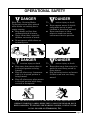
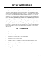
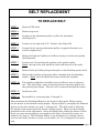
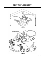
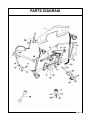
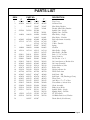
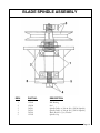
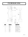
FINISHING
MOWER
Operation, Service
& Parts Manual For
FM-60, FM-72,
SFM-72, & SFM-84
February 2000
FORM: FinishingMowerBook.QXD
TABLE OF CONTENTS
Introduction . . . . . . . . . . . . . . . . . . . . . . . . . . . . .1
Safe Operating Rules . . . . . . . . . . . . . . . . . . . . . .2
Operational Safety . . . . . . . . . . . . . . . . . . . . . .3-4
Set-up Instructions . . . . . . . . . . . . . . . . . . . . . . .5
Belt Replacement . . . . . . . . . . . . . . . . . . . . . . .6-7
Parts Diagram . . . . . . . . . . . . . . . . . . . . . . . . . . .8
Parts List . . . . . . . . . . . . . . . . . . . . . . . . . . . . . . .9
Gearbox Assembly . . . . . . . . . . . . . . . . . . . .10-11
Blade Spindle Assembly . . . . . . . . . . . . . . . . . .12
Driveline . . . . . . . . . . . . . . . . . . . . . . . . . . . . . . .13
Limited Warranty . . . . . . . . . . . . . . . . . . . . . . .14
Date of Purchase:_____________________________
Model Number:_______________________________
Serial Number _______________________________
INTRODUCTION
We welcome you as an owner of a Gearmore mower. Please read the
following instructions and refer to them when required.
This manual contains valuable information about your new Gearmore
Mower. It has been carefully prepared to give you helpful suggestions
for operating, adjusting, servicing and ordering repair parts.
Keep this manual in a convenient place for quick and easy reference.
Study it carefully. You have purchased a dependable and sturdy mower,
but only by proper care and operation can you expect to receive the service
and long life designed and built into it.
Sometime in the future your mower may need new parts to replace those
that are worn or broken. If so, go to your dealer and provide him with the
model and part number.
CAUTION NOTE:
This mower is designed for and must be operated
with a 540 rpm PTO.
BEFORE PUTTING MOWER INTO SERVICE
1.
Fill gearbox with 90 to 140 weight gear oil. Fill through 1/2" pipe plug hole
to 1/8" pipe plug hole.
2.
Fill all (3) spindle units with grease until full. There are (3) grease access
holes for greasing spindle units in top cover.
3.
Grease all wheel axles, wheel forks, front roller axle, and PTO shaft.
4.
Check air pressure in tires, maintain rated psi listed on the tire at all
times.
5.
Check all nuts, bolts and belts to insure they are tight and secure.
NOTE:
Grease every 8 hours
Page 1
SAFE OPERATING RULES
1.
The area to be mowed should be a clean area, free of debris.
2.
Do not operate on steep hillsides.
3.
Do not allow passengers on tractor or mower.
4.
Keep all safety shields in place at all times.
5.
Always shut mower and tractor completely off before performing any
maintenance on mower.
6.
Disengage tractor PTO before getting off the tractor.
7.
Never operate mower while it is in a raised position.
8.
Never place any part of your body under the mower at any time.
9.
Always keep hands and feet away from the mower when it is in operation.
10.
A violation of these rules could result in a serious injury or death.
Use Proper Tractor Size To Match Mower
OPERATE MOWER AT 540 PTO RPM ONLY
Check all bolts and adjustments regularly to make sure they are tight.
Adhere to all warnings on following page.
SHIPPED WITHOUT OIL IN GEARBOX AND
WITHOUT GREASE IN GREASE FITTINGS.
UNIT MUST BE SERVICED BEFORE USING.
There are three (3) cutting height adjustment spacers from 1/2" to 1 1/2" (see
drawing on page 7 reference #1).
Page 2
OPERATIONAL SAFETY
FAILURE TO OBSERVE THE FOLLOWING
MAY RESULT IN SERIOUS INJURY
OR DEATH.
ONLY A PROPERLY TRAINED OPERATOR SHOULD
OPERATE THIS MOWER. KEEP ALL OTHERS OFF
TRACTOR AND MOWER.
NEVER ALLOW CHILDREN TO OPERATE
TRACTOR AND MOWER.
BEFORE OPERATING MOWER:
1.
2.
3.
4.
Read operator’s manual carefully for safe operation of this mower.
Do not remove shields and guards.
Make sure universal joints turn freely and are locked into tractor and
implement drive shafts.
Check area for any objects which may be thrown by mower.
WHILE OPERATING MOWER:
1.
2.
3.
4.
5.
6.
7.
Operate mower at 540 RPM PTO.
Stay on tractor seat at all times while mower is in operation.
Never allow passengers to ride on tractor or mower, nor carry children on
tractor or mower.
Alway stop mower in raised position and disengage PTO power before
transporting mower from one location to another.
Always stop engine before leaving tractor seat.
Always disengage the PTO before leaving the tractor seat.
Never adjust, clean or unstop mower when engine is running.
FOR THE SAFETY OF YOURSELF AND OTHERS:
1.
2.
3.
4.
5.
Keep yourself, others and clothing away from the rotating PTO.
Keep others away from area to be mowed to avoid injury from flying objects.
Use mower only with tractors that have factory installed seats.
Adjust, check and lubricate mower as recommended in operator’s manual.
Never stand between mower and tractor.
Page 3
OPERATIONAL SAFETY
DANGER
Keep away - Rotating Blades
To prevent serious njury ordeath
when blades are rotating due to
engine running.
* Keep hands and feet from
underneath deck of mower.
* Never allow riders, especially
children, on tractor or mower.
* Do not operate while others are
in mowing area.
DANGER
To prevent serious injury or death
* Keep away from mower when it
is in raised position or being
lowered.
* Keep all others away frommower
when it is in raised position or
being lowered.
* Keep all others away when mower
is in raised position while being
serviced or transported.
IT
DANGER
To prevent serious injury or death
* Never operate mower if shields
and guards are not in good
condition or have been removed.
* Never stand near or allow
others to stand near tractor
and mower when in operation.
DANGER
To prevent serious injury or death
* Keep others away from area to be
mowed to avoid being struck by
flying objects.
* Stop operating tractor and mower
if others come onto area being
mowed.
IS THE RESPONSIBILITY OF THE OWNER OF THIS EQUIPMENT TO
REPLACE WARNING LABELS WHEN THEY CANNOT BE READ OR HAVE
BEEN DAMAGED.
TO
OBTAIN NEW WARNING LABELS, CONTACT YOUR
LOCAL DEALER OR
GEARMORE, INC.
Page 4
SET-UP INSTRUCTIONS
Your Gearmore Finishing Mower has been carefully assembled at the factory. By following a
few simple instructions, your Finishing Mower will be ready for dependable service.
This Finishing Mower is designed to fit most tractors equipped with a standard three (3) point
system. The lift pins on the mower are classified as Category I. The Finishing Mower is shipped
from the factory with a safety shielded PTO shaft. This mower is designed to mow grass only.
Before placing your Gearmore Finishing Mower in service, please follow these instructions very
carefully. Your mower was shipped from the factory with no oil in the gearbox nor grease
in blade spindles and wheel axles. Fill the gearbox approximately one-third full with at least
90 weight oil. Grease the PTO shaft in two places before putting in service and after every
eight hours use. Grease the roller after every eight hours of use. There are three (3) blade spindle housings. The tops of each blade spindle housing are visible through three (3) access holes
in the top safety shield. Grease these blade spindle housings through the top of the shaft
before placing in service and after eight hours use. Adjust belts as necessary, keeping them tight
but not over-tight. When properly adjusted, belt should have approximately 3/4 inch deflection
with 10 lb. pull.
TO ADJUST BELT
1.
Remove top cover.
2.
Release adjustment spring.
3.
Loosen nut on adjustment pulley to allow for movement.
4.
Loosen nut on right side of "L" bracket.
5.
Turn nut on left side of "L" bracket in counterclockwise direction until belt is tight.
6.
Re-tighten nut on right side of "L" bracket and nut on adjustment pulley.
7.
Re-hook adjustment spring.
8.
See Figure D.
Page 5
BELT REPLACEMENT
TO REPLACE BELT:
STEP 1
Remove PTO shaft.
STEP 2
Remove top cover.
STEP 3
Loosen nut on adjustment pulley to allow for movement.
(See Figure D)
STEP 4
Loosen nut on right side of “L” bracket. (See Figure D)
STEP 5
Loosen belt by moving adjustment pulley in opposite direction you
would to tighten belt.
STEP 6
Remove belt from all pulleys and idlers, leaving it on the main pulley.
(See Figure E)
STEP 7
Loosen nuts (4) retaining the gearbox to the gearbox plate.
Note: the top of the nuts should be flush with the end of the bolts.
STEP 8
Remove bolts (4) holding the gearbox plate to the finishing mower deck.
STEP 9
Remove the gearbox and gearbox plate assembly from the finishing
mower. Note: the belt should be removed with the assembly.
STEP 10
Turn gearbox and plate assembly over and allow to rest on the gear
box. This will allow a space to develop between the main pulley and
the gearbox plate flange. The belt can be removed through this space.
STEP 11
Install new belt.
STEP 12
Reassemble by reversing steps 1 through 10.
After mounting the Finishing Mower to the tractor’s three point lifting system,
set the mower to the desired cutting height. Adjust height by arranging the different
spacers on the four wheels, see page 7, reference #1. This will result in relieving
the weight of the mower from the tractor’s lifting system. There are three height
positions for the chain adjustment. Select the height that allows the mower to float
freely over any terrain without any weight on the three (3) point lift system, see
reference 25, page 8. The Finishing Mower is not designed to cut foreign objects
such as steel rods, old tires or tubes, or tree limbs, etc. It is designed to cut grass
only.
Page 6
BELT REPLACEMENT
Page 7
PARTS DIAGRAM
Page 8
PARTS LIST
REF#
1
2
3
3
4
4
5
5
6
7
7
8
9
10
10
11
12
13
14
15
16
17
18
19
20
21
22
23
24
25
26
27
27
28
29
30
4'
403684
403024
502300
164090
403682
167112
184000
165114
502011
502010
500001
502012
403662
502110
403670
502120
403700
403665
403630
403023
502125
502015
502690
502316
502311
147022
502310
-
PART NO.
5'
6'
124685 124686
403025 403025
312647 312647
312641
502300 502300
502301
164090 164090
164105
403688 403688
167133 167148
167149
502027 502027
184000 184000
165114 165112
165113
502011 502011
502010 502010
500001 500001
502012 502012
403662 403662
502110 502110
403670 403670
502120 502120
403700 403700
403667 403667
403678 403678
403023 403023
502125 502125
502020 502020
502690 502690
502320 502324
502311 502311
502312
147022 147022
502310 502310
102287 102287
DESCRIPTION
7'
403687
403025
312647
312641
502301
164090
164091
403688
167162
167163
502027
184005
165114
165155
502011
502010
500001
502012
403662
502110
403670
502120
403700
403668
403679
403023
502125
502020
502690
502328
502311
502312
147022
502310
-
Top Cover
Gearbox Plate
Idler Pulley Bracket
Double Idler Pulley Bracket
Spindle Unit - Single
Spindle Unit - Double
Idler Pulley - Single
Idler Pulley - Double
Belt Adjustment Assembly
V-Belt
V-Belt - Double
Spring
Gearbox
Main Pulley - Single
Main Pulley - Double
Bolt 3/4" x 4" w/Nut
Swivel Link Set
Lift Pin Set - Cat. I
Lift Arm Spacer w/Bolt & Nut
Lift Arm Assembly
Center Roller w/Axle
Roller Axle
Height Adjuster Set
Wheel Fork Arm
Side Panel - RH
Side Panel - LH (Discharge Chute)
Wheel Fork
Axle Bolt 3/4" x 5" w/Nut
Tire & Rim w/Axle & Nut
Chain Assembly
Blade Set w/Bolts
Spindle Pulley - Single
Spindle Pulley - Double
22" PTO Shaft
LH Blade Bolt Set w/Washer
Plastic Knob (Not Shown)
Page 9
GEARBOX ASSEMBLY
Page 10
GEARBOX ASSEMBLY
REF#
1
2
2
3
4
5
6
7
8
9
9
10
11
12
13
14
15
16
17
18
19
20
PART NO.
DESCRIPTION
155005
185007
185010
131031
186010
155010
129010
131035
131040
185005
185006
131045
156010
129015
124130
131030
156005
124131
129005
501110
Bearing
Input Gear - 184000 Gearbox
Input Gear - 184005 Gearbox
Snap Ring
Input Shaft
Bearing
Housing
1/2" Pipe Plug
1/8" Pipe Plug
Output Shaft - 184000 Gearbox
Output Shaft - 184005 Gearbox
Spacer
3/8" x 1 3/4" Bolt
3/8" Lock Washer
Input Seal
Front Cover
Front Cap Gasket
Snap Ring
Output Seal
Gasket
Bottom Cover
1" Castle Nut w/Washer & Cotter
Page 11
BLADE SPINDLE ASSEMBLY
REF#
1
2
3
3
4
5
PART NO.
DESCRIPTION
155009
156026
502311
502312
502310
191302
Ball Bearing
Seal
Spindle Pulley w/Nut & Key (502300 Spindle)
Spindle Pulley w/Nut & Key (502301 Spindle)
Blade Bolt Set (3) w/Washer
Spindle Cap
Page 12
PTO DRIVELINE 147022
REF#
1
2
3
4
5
6
7
8
9
10
PART NO.
DESCRIPTION
170120
151045
151040
151050
151035
151091
151090
170015
170110
124310
Roll Pin
Male Tube End Yoke
Implement End Yoke
Female Tube End Yoke
Tractor End Yoke
Inner Tube 14 Series
Outer Tube 14 Series
Cross Kit #4
Quick Disconnect Pin
Series 14 Safety Shield
Page 13
LIMITED WARRANTY
GEARMORE, INC., warrants each new Gearmore product to be free from defects in material and workmanship for a period of twelve (12) months from date of purchase to the original
purchaser. This warranty shall not apply to implements or parts that have been subject to
misuse, negligence, accident, or that have been altered in any way.
Our obligation shall be limited to repairing or replacement of any part, provided that such
part is returned within thirty (30) days from date of failure to Gearmore through the dealer
from whom the purchase was made, transportation charges prepaid.
This warranty shall not be interpreted to render us liable for injury or damages of any kind or
nature, direct, consequential or contingent, to person or property. This warranty does not
extend to loss of crops, loss because of delay in harvesting or any other expenses, for any
other reasons.
Gearmore in no way warranties engines, tires, or other trade accessories, since these items
are warranted separately by these respective manufacturers.
Gearmore reserves the right to make improvements in design or changes in specification at
any time, without incurring any obligations to owners or units previously sold.
GEARMORE, INC.
13477 Benson Ave.
Chino, CA 91710
Always refer to and heed machine operating warning decals on machine.
The serial number of this product is stored in our computer database, thus
submitting a warranty registration card is not required.
Page 14