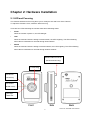
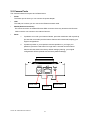
1
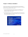
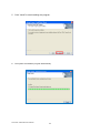
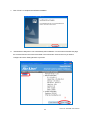
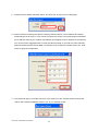
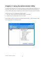
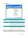
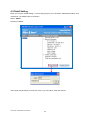
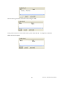
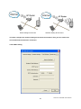
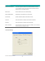
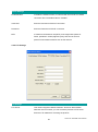
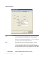
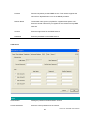
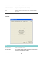
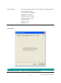
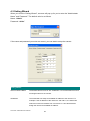
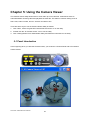
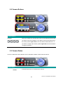
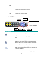
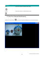
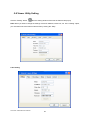
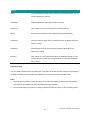
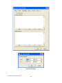
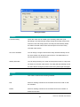
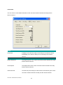
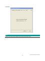
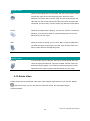
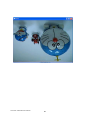
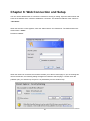
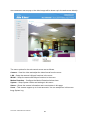
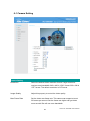
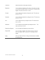
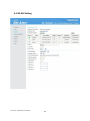
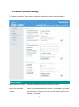
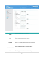
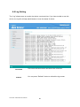
WL-1000CAM Wireless-G Motion JPEG Camera User’s Manual Declaration of Conformity We, Manufacturer/Importer OvisLink Corp. 5F., NO.6, Lane 130, Min-Chuan Rd., Hsin-Tien City, Taipei County, Taiwan Declare that the product Wireless-G Motion JPEG Camera AirLive WL-1000CAM is in conformity with In accordance with 89/336 EEC-EMC Directive and 1999/5 EC-R & TTE Directive Clause Description ■ EN Electromagnetic compatibility and Radio spectrum Matters (ERM); Wideband transmission equipment operating in the 2.4GHz ISM band And using spread spectrum modulation techniques; Part 1:technical Characteristics and test conditions Part2:Harmonized EN covering Essential requirements under article 3.2 of the R&TTE Directive ■ EN Electromagnetic compatibility and Radio spectrum Matters (ERM); Electromagnetic compatibility(EMC) standard for radio equipment and Services; Part 17:Specific conditions for wideband data and HIPERLAN equipment 300 328 v1.7.1 (2006-05) 301 489-1 V1.5.1 (2004-11) ■ EN 301 489-17 V1.2.1 (2002-08) ■ EN 50371:2002 Generic standard to demonstrate the compliance of low power Electronic and electrical apparatus with the basic restrictions related to human exposure to electromagnetic field (10MHz – 300GHz) -General public ■ EN 60950-1:2001/A11 Safety for information technology equipment including electrical :2004 business equipment ■ CE marking Manufacturer/Importer Signature : Name : Position/ Title: Albert Yeh Vice President (Stamp) Date: 2008/2/13 AirLive WL-1000CAM CE Declaration Statement Country cs Česky [Czech] Declaration OvisLink Corp. tímto prohlašuje, že tento AirLive WL-1000CAM je ve shodě se základními požadavky a dalšími příslušnými ustanoveními směrnice 1999/5/ES. da Undertegnede OvisLink Corp. erklærer herved, Dansk [Danish] at følgende udstyr AirLive WL-1000CAM overholder de væsentlige krav og øvrige relevante krav i direktiv 1999/5/EF. de Hiermit erklärt OvisLink Corp., dass sich das Deutsch Gerät AirLive WL-1000CAM in Übereinstimmung [German] mit den grundlegenden Anforderungen und den übrigen einschlägigen Bestimmungen der Richtlinie 1999/5/EG befindet. et Käesolevaga kinnitab OvisLink Corp. seadme Eesti [Estonian] AirLive WL-1000CAM vastavust direktiivi 1999/5/EÜ põhinõuetele ja nimetatud direktiivist tulenevatele teistele asjakohastele sätetele. en Hereby, OvisLink Corp., declares that this AirLive English WL-1000CAM is in compliance with the essential requirements and other relevant provisions of Directive 1999/5/EC. es Por medio de la presente OvisLink Corp. declara Español que el AirLive WL-1000CAM cumple con los [Spanish] requisitos esenciales y cualesquiera otras disposiciones aplicables o exigibles de la Directiva 1999/5/CE. el ΜΕ ΤΗΝ ΠΑΡΟΥΣΑ OvisLink Corp. ΔΗΛΩΝΕΙ Ελληνική [Greek] ΟΤΙ AirLive WL-1000CAM ΣΥΜΜΟΡΦΩΝΕΤΑΙ ΠΡΟΣ ΤΙΣ ΟΥΣΙΩΔΕΙΣ ΑΠΑΙΤΗΣΕΙΣ ΚΑΙ ΤΙΣ ΛΟΙΠΕΣ ΣΧΕΤΙΚΕΣ ΔΙΑΤΑΞΕΙΣ ΤΗΣ ΟΔΗΓΙΑΣ 1999/5/ΕΚ. fr Par la présente OvisLink Corp. déclare que Français [French] l'appareil AirLive WL-1000CAM est conforme aux exigences essentielles et aux autres dispositions pertinentes de la directive 1999/5/CE it Con la presente OvisLink Corp. dichiara che Italiano [Italian] questo AirLive WL-1000CAM è conforme ai requisiti essenziali ed alle altre disposizioni pertinenti stabilite dalla direttiva 1999/5/CE. lv Ar šo OvisLink Corp. deklarē, ka AirLive WLLatviski [Latvian] 1000CAM atbilst Direktīvas 1999/5/EK būtiskajām prasībām un citiem ar to saistītajiem noteikumiem. sv Härmed intygar OvisLink Corp. att denna AirLive Svenska WL-1000CAM står I överensstämmelse med de [Swedish] väsentliga egenskapskrav och övriga relevanta bestämmelser som framgår av direktiv 1999/5/EG. Country lt Lietuvių [Lithuanian] Declaration Šiuo OvisLink Corp. deklaruoja, kad šis AirLive WL1000CAM atitinka esminius reikalavimus ir kitas 1999/5/EB Direktyvos nuostatas. nl Hierbij verklaart OvisLink Corp. dat het toestel AirLive Nederlands [Dutch WL-1000CAM in overeenstemming is met de essentiële eisen en de andere relevante bepalingen van richtlijn 1999/5/EG. mt Hawnhekk, OvisLink Corp, jiddikjara li dan AirLive Malti [Maltese] WL-1000CAM jikkonforma mal-ħtiġijiet essenzjali u ma provvedimenti oħrajn relevanti li hemm fidDirrettiva 1999/5/EC. hu Magyar [Hungarian] pt Português [Portuguese] Az OvisLink Corporation kijelenti, hogy az AirLive WL-1000CAM megfelel az 1999/05/CE irányelv alapvető követelményeinek és egyéb vonatkozó rendelkezéseinek. Niniejszym OvisLink Corp oświadcza, że AirLive WL1000CAM jest zgodny z zasadniczymi wymogami oraz pozostałymi stosownymi postanowieniami Dyrektywy 1999/5/EC. OvisLink Corp declara que este AirLive WL-1000CAM está conforme com os requisitos essenciais e outras disposições da Directiva 1999/5/CE. sl Slovensko [Slovenian] OvisLink Corp izjavlja, da je ta AirLive WL-1000CAM v skladu z bistvenimi zahtevami in ostalimi relevantnimi določili direktive 1999/5/ES. pl Polski [Polish] sk OvisLink Corp týmto vyhlasuje, že AirLive WLSlovensky [Slovak] 1000CAM spĺňa základné požiadavky a všetky príslušné ustanovenia Smernice 1999/5/ES. fi Suomi [Finnish] OvisLink Corp vakuuttaa täten että AirLive WL1000CAM tyyppinen laite on direktiivin 1999/5/EY oleellisten vaatimusten ja sitä koskevien direktiivin muiden ehtojen mukainen Hér með lýsir OvisLink Corp yfir því að AirLive WLÍslenska [Icelandic] 1000CAM er í samræmi við grunnkröfur og aðrar kröfur, sem gerðar eru í tilskipun 1999/5/EC. no OvisLink Corp erklærer herved at utstyret AirLive WLNorsk [Norwegian] 1000CAM er i samsvar med de grunnleggende krav og øvrige relevante krav i direktiv 1999/5/EF. A copy of the full CE report can be obtained from the following address: OvisLink Corp. 5F, No.6 Lane 130, Min-Chuan Rd, Hsin-Tien City, Taipei, Taiwan, R.O.C. This equipment may be used in AT, BE, CY, CZ, DK, EE, FI, FR, DE, GR, HU, IE, IT, LV, LT, LU, MT, NL, PL, PT, SK, SI, ES, SE, GB, IS, LI, NO, CH, BG, RO, TR Federal Communication Commission Interference Statement This equipment has been tested and found to comply with the limits for a Class B digital device, pursuant to Part 15 of FCC Rules. These limits are designed to provide reasonable protection against harmful interference in a residential installation. This equipment generates, uses, and can radiate radio frequency energy and, if not installed and used in accordance with the instructions, may cause harmful interference to radio communications. However, there is no guarantee that interference will not occur in a particular installation. If this equipment does cause harmful interference to radio or television reception, which can be determined by turning the equipment off and on, the user is encouraged to try to correct the interference by one or more of the following measures: 1. Reorient or relocate the receiving antenna. 2. Increase the separation between the equipment and receiver. 3. Connect the equipment into an outlet on a circuit different from that to which the receiver is connected. 4. Consult the dealer or an experienced radio technician for help. FCC Caution This device and its antenna must not be co-located or operating in conjunction with any other antenna or transmitter. This device complies with Part 15 of the FCC Rules. Operation is subject to the following two conditions: (1) this device may not cause harmful interference, and (2) this device must accept any interference received, including interference that may cause undesired operation. Any changes or modifications not expressly approved by the party responsible for compliance could void the authority to operate equipment. IMPORTANT NOTE: FCC Radiation Exposure Statement: This equipment complies with FCC radiation exposure limits set forth for an uncontrolled environment. This equipment should be installed and operated with minimum distance 20cm between the radiator & your body. This transmitter must not be co-located or operating in conjunction with any other antenna or transmitter. COPYRIGHT Copyright © 2007 by OvisLink Corp. All rights reserved. No part of this publication may be reproduced, transmitted, transcribed, stored in a retrieval system, or translated into any language or computer language, in any form or by any means, electronic, mechanical, magnetic, optical, chemical, manual or otherwise, without the prior written permission of OvisLink Corp. OvisLink Corp. makes no representations or warranties, either expressed or implied, with respect to the contents hereof and specifically disclaims any warranties, merchantability or fitness for any particular purpose. Any software described in this manual is sold or licensed "as is". Should the programs prove defective following their purchase, the buyer (and not this company, its distributor, or its dealer) assumes the entire cost of all necessary servicing, repair, and any incidental or consequential damages resulting from any defect in the software. Further, this company reserves the right to revise this publication and to make changes from time to time in the contents thereof without obligation to notify any person of such revision or changes. AirLive WL-1000CAM User’s Manual 1 TABLE OF CONTENT CHAPTER 1: PRODUCT INFORMATION ............................................................................. 6 1-1 INTRODUCTION .................................................................................................... 6 1-2 PACKAGE CONTENT ............................................................................................. 6 1-3 SYSTEM REQUIREMENTS ...................................................................................... 6 CHAPTER 2: HARDWARE INSTALLATION ........................................................................... 7 2-1 LED AND FOCUSING ............................................................................................ 7 2-2 CAMERA PORTS ................................................................................................... 8 CHAPTER 3: SOFTWARE INSTALLATION ...........................................................................10 CHAPTER 4: USING THE ADMINISTRATOR UTILITY ...........................................................16 4-1 GENERAL SETTING ............................................................................................. 17 4-2 DETAIL SETTING................................................................................................. 18 4-2-1 Network Setting ........................................................................................ 19 4-2-2 Wireless Settings (*Wireless Model Only) ................................................ 20 4-2-3 E-Mail Setting ........................................................................................... 23 4-2-4 PPPoE Settings ........................................................................................ 24 4-2-5 FTP Settings ............................................................................................. 25 4-2-6 Date / Time Settings ................................................................................. 26 4-2-7 Resolution ................................................................................................. 27 4-2-8 Advanced Setting ...................................................................................... 28 4-2-9 Users ........................................................................................................ 29 4-2-10 Tools ....................................................................................................... 30 4-2-11 About ....................................................................................................... 31 4-3 SETTING W IZARD ............................................................................................... 32 CHAPTER 5: USING THE CAMERA VIEWER .......................................................................34 5-1 PANEL INTRODUCTION ........................................................................................ 34 5-2 CAMERA BUTTONS ............................................................................................. 35 5-3 CAMERA STATUS ................................................................................................ 35 5-4 CONTROL BUTTONS ........................................................................................... 36 5-5 VIDEO RECORDING ............................................................................................ 37 5-6 CHANGE RESOLUTION ........................................................................................ 38 5-7 VIEW FOUR CAMERAS SIMULTANEOUSLY ............................................................. 39 5-8 VIEWER UTILITY SETTING ................................................................................... 40 5-8-1 Setting ...................................................................................................... 40 5-8-2 Recording ................................................................................................. 41 AirLive WL-1000CAM User’s Manual 4 5-8-3 Status........................................................................................................ 44 5-8-4 General ..................................................................................................... 45 5-8-5 About ........................................................................................................ 47 5-9 PLAYBACK ......................................................................................................... 48 5-10 ROTATE VIDEO................................................................................................. 49 CHAPTER 6: WEB CONNECTION AND SETUP ....................................................................51 6-1 CAMERA SETTING .............................................................................................. 53 6-2 LAN SETTING .................................................................................................... 55 6-3 WLAN SETTING ................................................................................................ 58 6-4 MOTION DETECTION SETTINGS ........................................................................... 61 6-5 SYSTEM SETTINGS ............................................................................................. 62 6-6 STATUS SETTINGS.............................................................................................. 64 6-7 USERS SETTINGS .............................................................................................. 64 6-8 LOG SETTING .................................................................................................... 66 CHAPTER 7: FREQUENTLY ASKED QUESTIONS..................................................................67 CHAPTER 8: TECHNICAL SPECIFICATIONS.........................................................................68 AirLive WL-1000CAM User’s Manual 5 Chapter 1: Product Information 1-1 Introduction Thank you for choosing the Internet Camera. This Internet Camera sends live video through 10/100Mbps wired network to a web browser or camera viewer across Internet anywhere in the world! This compact, self-contained unit lets you keep an eye on your home, your kids, and your workplace—whatever’s important to you. How does the Camera do all of this? Unlike standard ―web cams‖ that require an attached PC, the Internet Camera can connect directly to a network. The MJPEG video compression produces a high quality, high-frame rate, 640 x 480 video streams. The included Camera Viewer utility lets you record the video to your local hard drive, ―live‖ or on a predetermined schedule. Use the instructions in this Guide to help you integrate the Camera into your network. These instructions should be all you need to get the most out of the Internet Camera. 1-2 Package Content One Internet Camera One Power Adapter One Camera Stand One Ethernet Cable One Quick Installation Guide One CD (Including Manual/Utility/Driver) One 2dBi Antenna If any of the above items are missing, please contact your supplier. 1-3 System Requirements System requirement for PC, MAC or Notebook PC to access the Internet Camera are: OS System: Windows 98 , ME , 2000, XP + SP2, Server 2003 IE Version: 6.0.29 + SP2 CPU: Intel Pentium III 750MHz above or Intel Celeron 1GHz above Memory Size: 128MB (256MB recommended) DirectX 9.0 or above VGA card with fully DirectX 9.0 supported. VGA Card Resolution: 800 x 600 or above or above AirLive WL-1000CAM User’s Manual 6 Chapter 2: Hardware Installation 2-1 LED and Focusing The Camera head and its focus ring allow you to modify the aim and focus of the Camera. To adjust the Camera’s focus, rotate the dark focus ring. There are four LEDs indicating the camera status and networking status. Power When the camera is power on, the LED will light. LAN When the Internet Camera is linking to wired network, the LED is lighting. The LED is flashing when video is transmitted or received through wired network. WLAN When the Internet Camera is linking to wireless network, the LED is lighting. The LED is flashing when video is transmitted or received through wireless network. Wireless SMA Connector (Wireless Model Only) Focus Ring LED Green: LAN Activity LED Amber: WLAN Activity LED Blue: Power On AirLive WL-1000CAM User’s Manual 7 2-2 Camera Ports The Camera features three ports and a Reset button. y Power The Power port is where you can connect the power adapter. y LAN The LAN port is where you can connect the Ethernet network cable. y WLAN (Antenna Connector) This round connection is standard Reverse SMA connector where any antennas with Reverse SMA connector can connect to the Internet Camera.. y Reset 1. If problems occur with your Internet Camera, press the reset button with a pencil tip (for less than 2 seconds) and the Internet Camera will re-boot itself, keeping your original configurations. 2. If problems persist or you experience extreme problems or you forgot your password, press the reset button for longer than 5 seconds and the Internet Camera will reset itself to the factory default settings (warning: your original configurations will be replaced with the factory default settings). 改圖 Power Jack LAN Port AirLive WL-1000CAM User’s Manual 8 Reset Button 2-3 Installation Procedure 1. Unpack the Internet Camera package and verify that all the items listed in the Chapter 2 are provided. 2. Connect the Internet Camera to your network by attached the network cable from the switch/router to the UTP port of the Internet Camera. 3. Connect the power adapter to the Internet Camera and plug the power adapter to power outlet. The Internet Camera will be powered on. When the Internet Camera is ready, the Ready LED will light. 4. Make sure that you have installed correct VGA driver and DirectX 9.0 or above. Note: It is highly recommended to use the power adapter shipped with the Internet Camera, do NOT use any other power adapter from any sources. AirLive WL-1000CAM User’s Manual 9 Chapter 3: Software Installation Follow the simple steps below to run the Install Wizard to guide you quickly through the Installation process. The following installation is implemented in Windows XP. The installation procedures in Windows 2000/Server 2003 are similar. 1. Insert the CD shipped along with the Internet Camera into your CD-ROM drive. The ―Autorun.exe‖ program should be executed automatically. If not, run ―Autorun.exe‖ manually from ―Autorun‖ folder in the CD. 2. The Install Wizard will show six selections, select the program you want to install or click ―Exit‖ to install the program later. The following installation steps are the demonstration of ―Install Administrator Utility & Camera Viewer‖. AirLive WL-1000CAM User’s Manual 10 3. The system will start the installation procedures. Click ―Next‖ to continue installation. 4. If you wish to install the software program in an alternate location, click ―Change‖; otherwise click ―Next‖ to move on to the next step. AirLive WL-1000CAM User’s Manual 11 5. Click ―Install‖ to start installing the program. 6. The system will install the program automatically. AirLive WL-1000CAM User’s Manual 12 7. Click ―Finish‖ to complete the software installation. 8. ‖Administrator Utility―will be run automatically after installation. On the Internet Camera first page, the cameras found in the network are listed in the left window. Choose the one you want to configure and click ―Setting Wizard‖ to proceed. ―N‖ means the camera is new and not configured. AirLive WL-1000CAM User’s Manual 13 9. Please enter the default password ―airlive‖ and click ―OK‖ to login to the IP setup page. 10. Internet Camera is working through the network (TCP/IP Protocol). The IP address and subnet mask setting must be correct, or you cannot access to the camera. The wizard program will detect the IP address status of your network automatically and suggest a free IP address for the Camera. You can accept the suggested value or enter the value manually. If you enter the value manually, please be aware that the ―Subnet Mask‖ must be the same for both the camera and the PC. Click ―Next‖ to apply the configuration. 11. This wizard will pop up a window to ask you if you want to run the ―Camera Viewer‖ and see the video of the Camera immediately. Select ―Yes‖ to run ―Camera Viewer‖. AirLive WL-1000CAM User’s Manual 14 12. The ―Camera Viewer‖ will show the video automatically. Congratulations, you can use the camera through the network to view the video from now on. AirLive WL-1000CAM User’s Manual 15 Chapter 4: Using the Administrator Utility The Administrator Utility allows users to search and setup the cameras located within the Intranet or on the Internet. From the utility, users can view all the information of the selected camera; furthermore, it provides a setting wizard, which can guide users to add the camera to the network easily and promptly. There are two ways to run the Administrator Utility as follows. 1. Click ―Start‖, select ―Programs\IP Camera\Admin Utility‖ to run the utility. 2. Double click the ―IP Camera Admin‖ icon to run the utility. Once the utility is started, it will search all the cameras within the network. To do more settings, please refer to the description in the following sections. AirLive WL-1000CAM User’s Manual 16 4-1 General Setting LAN Auto Discover Click the button will search the camera within the network. Information of Camera Camera Information It displays all information of the selected camera. The information includes Firmware Version, Network Information, IP Address, UPnP Setting, DDNS Setting, Resolution and E-mail setting, etc. Camera Setting Detail Setting Click ―Detail Setting‖ to do more setting of the camera such as IP address, Resolution, password and firmware upgrade, etc. Setting Wizard Click ―Setting Wizard‖ to setup the necessary setting for the camera. AirLive WL-1000CAM User’s Manual 17 4-2 Detail Setting When you click the ―Detail Setting‖, a screen will pop up for you to enter the ―Administrator Name‖ and ―Password‖. The default value is as follows. Name: ―Admin‖ Password: ―airlive‖ If the name and password you enter are correct, you can start to setup the camera. AirLive WL-1000CAM User’s Manual 18 4-2-1 Network Setting AIRLIVE 192 . 168. 2. 3 192 . 168. 2. 1 Network Setting Internet Camera Name The default camera name is ―WL-1000CAM‖. It is recommended to name a meaningful name for the camera. IP Address Enter an unused IP Address within the IP address range used on your LAN. If the IP Address of your LAN is from the 192.168.2.1 to 192.168.2.254, you can set an unused IP Address from the range for the camera, for example: 192.168.2.250. Subnet Mask The Subnet Mask field must match the subnet setting on your LAN. For example: 255.255.255.0. Gateway The Gateway is used to forward frames to destinations in a different subnet on the Internet. The Gateway setting must be the same with the gateway used by the PCs on your LAN. AirLive WL-1000CAM User’s Manual 19 DNS Server DNS Server (Domain Name Server) that translates names to IP addresses. Set the same DNS Server as the PCs on your LAN. Network Setting Video Port The Video Port is used to transmit or receive the video streaming in the network. The default port setting is ―4321‖. If you want to view the video from the camera, the port setting should be correct. Web Port This camera support web connection, the default web port is 80. Since the web server may use port 80, you can use a different port for the camera. If you change the web port from 80 to 8080, you must type http://192.168.2.3:8080 to connect the camera through the web browser. 4-2-2 Wireless Settings (*Wireless Model Only) airlive Utility will site survey automatically or you can press ―Refresh‖ button to survey the AP router manually. AirLive WL-1000CAM User’s Manual 20 After site survey procedure, there will show existing AP SSID. airlive Then press ―Connect‖ to connect AP router or press ―Add to Profile‖ to configure the Wireless WEP and WPA encryption. airlive AirLive WL-1000CAM User’s Manual 21 airlive There are WEP(Open System/Shared Key) ,WPA-PSK,WPA2-PSK and WPANone encryption settings. You can choose one to match AP router wireless settings. After set the profile, Please remove the LAN cable then IP Camera will connect to AP router automatically. AirLive WL-1000CAM User’s Manual 22 Wired Setting Environment Wireless Setting Environment You must configure the wireless settings from wired environment. Then you can remove the wired cable and start wireless connection. 4-2-3 E-Mail Setting AirLive WL-1000CAM User’s Manual 23 E-Mail Setting Recipient E-Mail Address This camera supports ―Snap Shot‖ and ―Motion Detection‖ functions. You can snapshot a picture and send the picture by E-Mail. Enter the E-Mail Account for receiving the picture. SMTP Server Enter the SMTP Server for the E-Mail sending. Sender E-Mail Address Specified the e-mail address of the e-mail sender. Authentication Enable or Disable the SMTP Authentication function Username When Authentication is enabled, input the SMTP Username. Password When Authentication is enabled, input the password. Send a Test Email Press this button to send a test e-mail to your mailbox. You can use this function to test if your setting is correct. 4-2-4 PPPoE Settings AirLive WL-1000CAM User’s Manual 24 PPPoE Settings Enable/Disable If enable the PPPoE function, IP Camera will use PPPoE for network connection first. The default value is ―Disable‖. Username Enter the Username of PPPoE connection. Password Enter the Password of PPPoE connection MTU A maximum transmission unit (MTU) is the largest size packet or frame, specified in octets (eight-bit bytes), that can be sent in a packet or frame based network such as the Internet. 4-2-5 FTP Settings FTP Settings FTP Server This camera supports ―Motion Detection‖ functions. When Motion Detection event occurred, you can record the pictures to FTP server. Enter the FTP address for receiving the pictures. AirLive WL-1000CAM User’s Manual 25 FTP Port Enter the port of the FTP server. User Name Specify the user account of ftp server. Password Specify the Password of your ftp account. Remote Folder Specify the folder of the ftp site that you want to store the video. Passive Mode If your Camera is under NAT, you usually need to enable this feature. 4-2-6 Date / Time Settings Date / Time Settings Set Date/Time manually Set the current Date and Time. NTP Server Synchronize the Date and Time with NTP server. AirLive WL-1000CAM User’s Manual 26 Time Zone Select the time zone that your camera put on. NTP Server Specify the IP Address of the NTP Server. 4-2-7 Resolution Resolution Resolution Select the desired video resolution format. Larger resolution requires more bandwidth. 640 x 480 is ―VGA‖ format. 320 x 240 is ―CIF‖ format. 176 x 144 is ―QCIF‖ format. AirLive WL-1000CAM User’s Manual 27 4-2-8 Advanced Setting Advanced Setting UPnP When the UPnP function is enabled, the camera can be detected by UPnP compliant system such as Windows XP. The camera will be displayed in the Neighborhood of Windows XP, so you can directly click the camera to view the video through web browser. DDNS Many internet connections use a "Dynamic IP address", where the Internet IP address is allocated dynamically whenever the Internet connection is established. Internet users should know the IP Address of the camera when they want to connect to the camera every time. DDNS is designed to solve this problem, by allowing users to connect to your LAN using a domain name, rather than an IP address. Enable/Disable Enable or disable DDNS function of the camera. AirLive WL-1000CAM User’s Manual 28 Provider Several companies provide DDNS service. This camera supports the service from DynDNS who is one of the DDNS providers. Domain Name The domain name given by DynDNS is ―registername.dyndns.com‖. Enter the domain name that you register for the camera from DynDNS web site. Account Enter the login name for the DDNS service. Password Enter the password for the DDNS service. 4-2-9 Users Users Administrator Setting the password of Administrator account Current Password Enter the current password of the camera. AirLive WL-1000CAM User’s Manual 29 New Password Enter the new password you want to use for the camera. Confirm New Password Retype the new password to confirm the setting. User Setting the user account and password. Your camera can support 4 user account. 4-2-10 Tools Tools Firmware Version Display current firmware version. Firmware Update You can upgrade camera’s firmware via this function. Press this button and select the correct firmware to upgrade. AirLive WL-1000CAM User’s Manual 30 Reset to Default If you want to reset the camera, click this button. The default settings of the camera are as follows. Camera Name: ―WL-1000CAM‖ IP Address: ―192.168.2.3‖ Subnet Mask: 255.255.255.0 Administrator Name: ―Admin‖ Password: ―airlive‖ Video Port: ―4321‖ Web Port: ―80‖ 4-2-11 About About Administrator Utility Version Display current Administrator Utility Version. AirLive WL-1000CAM User’s Manual 31 4-3 Setting Wizard When you click the ―Setting Wizard‖, a screen will pop up for you to enter the ―Administrator Name‖ and ―Password‖. The default value is as follows. Name: ―Admin‖ Password: ―airlive‖ If the name and password you enter are correct, you can start to setup the camera. AIRLIVE 192 . 168. 2. 3 192 . 168. 2. 1 Setting Wizard Internet Camera Name The default camera name is ―WL-1000CAM‖. It is recommended to enter a meaningful name for the camera. IP Address The wizard will auto setup an available IP Address to the camera. For example: if the IP address of the network is 192.168.2.x, the wizard will search an unused IP Address from 192.168.2.1 to 192.168.2.250 and assign the camera an available IP Address. AirLive WL-1000CAM User’s Manual 32 You are allowed to enter another IP Address to change the setting. Subnet Mask The wizard will auto search the Subnet Mask setting of the network and set the camera in the same Subnet Mask. You can enter another Subnet Mask to change the setting. Gateway The wizard will auto search the Gateway setting of the network and set the camera to use the same Gateway. You can enter another Gateway to change the setting. Video Port It defines the video stream port. The default value is ―4321‖. Cancel Click ―Cancel‖ to stop wizard setting. Finish Click ―Finish‖ to complete the camera setting. When you finish the camera setting, you can click ―Ok‖ to run the ―Camera Viewer‖ immediately or click ―Cancel‖ to run the ―Camera Viewer‖ later. AirLive WL-1000CAM User’s Manual 33 Chapter 5: Using the Camera Viewer The Camera Viewer Utility allows users to view video up to four cameras. It also allows users to manual/schedule recording video and playback the video file. The status of camera viewing such as frame rate, video received, and etc. are also recorded in time. There are three ways to run the Camera Viewer Utility as follows. 1. Click ―Start‖, select ―Programs\IP Camera\Camera Viewer‖ to run the utility. 2. Double click the ―IP Camera Viewer‖ icon to run the utility. 3. Click ―Setting Wizard‖ from Administrator Utility and follow the instructions in the utility. 5-1 Panel Introduction In the beginning when you start the Camera Viewer, you would see a Control Panel and a four division Viewer window. AirLive WL-1000CAM User’s Manual 34 5-2 Camera Buttons Camera Buttons Camera Click one of these four cameras will connect to the selected camera that you want to view and configure. If you want to remove the camera from the viewer, please right click the icon and select ―Reset Camera x‖. If you want to configure the camera, please right click the icon and select ―Configure Camera x‖. 5-3 Camera Status There is a status bar shown different color to indicate the status of each Internet Camera. Camera Status YELLOW It means that there is no camera set to connect. AirLive WL-1000CAM User’s Manual 35 BLUE PINK RED It means that the camera is connected and playing the live video. It means that the camera is not connected now. It means that the camera is recording. 5-4 Control Buttons Pause Snapshot Close the Camera Viewer Minimize the Window Stop Record Play Forward Control Buttons Play The ―Play‖ button is an intelligent play user-interface. In the normal display mode and the Internet Camera is disconnected, clicking on the ―Play‖ can make the viewer connect to the Internet Camera. In the playback mode, clicking on the ―Play‖ can play the video in the normal speed. Stop The ―Stop‖ button is an intelligent play user-interface. In the normal display mode and the Internet Camera is connected, clicking on the ―Stop‖ can make the viewer disconnect the camera. In the playback mode, clicking on the ―Stop‖ can stop playing the video. Pause The ―Pause‖ button provides you a way to pause the current video display. When the displaying video is paused, click on the ―Play‖ again to resume the video display. Forward The ―Forward‖ button to forward the speed of display when playback the AirLive WL-1000CAM User’s Manual 36 recording file. Click the button at a time will increase the playing speed one time. Snapshot Click ―Snapshot‖ will make the viewer to take a snapshot of the video and save the picture as a bitmap file in the hard disk. (You can set the directory for storing these bitmap files at the Section 7.8.4) Record By clicking ―Record‖ you can record video immediately. (You can set the directory for storing video files at the section 7.8.4) 5-5 Video Recording This utility allows you record the video in AVI files. There are two ways of video recording – Manual Recording and Schedule Recording. Manual Recording You can manually record the video stream into an assigned video file. Click ―Record‖, then the viewer utility will start to record the video stream. You can assign the path in the setting dialog.(at section 7.8.4) Clicking ―Stop‖ will stop recording. Note: Before manual recording, you have to click the camera button to select the Internet Camera that you want to record first and make sure that the viewer is successfully connecting to the Internet Camera. Schedule Recording You can assign a schedule and let this viewer automatically recording the video stream. Please refer to Section 7.8 to see how to setup schedule for the recording. The file name of the recorded video file is the start time of recording. For example, the file name ―IPCamera_2004-10-8-23-56-40.avi‖ means it AirLive WL-1000CAM User’s Manual 37 was recorded at 2004/10/8 23:56:40. 5-6 Change Resolution The Internet Camera supports two resolution, 640x480 (VGA) and 320x240 (CIF). You can change the resolution of each Internet Camera by clicking the resolution button. Note: Before changing the resolution of the Internet Camera, you have to select the Internet Camera by clicking the camera button first. If you change the resolution of an Internet Camera, other clients who are viewing the same Internet Camera simultaneously will also see the video with the changed resolution, too. AirLive WL-1000CAM User’s Manual 38 Resolution VGA Change the resolution to 640x480 (VGA) mode. QVGA Change the resolution to 320x240 (QVGA) mode. 5-7 View Four Cameras Simultaneously Click the four division button can view the 4 cameras simultaneously in a four-division window. AirLive WL-1000CAM User’s Manual 39 5-8 Viewer Utility Setting Click the ―Setting‖ button , then the setting window of the Internet Camera will pop up. Note: When you want to change the settings such as IP Address, Video Port, etc. in the ―Setting‖ option, you must disconnect the Internet Camera first by clicking the ―Stop‖. 5-8-1 Setting AirLive WL-1000CAM User’s Manual 40 Setting Name It is not required to fill the camera name for connecting camera. It is for users to identify the camera. IP Address IP address/Domain name of the Internet Camera. Video Port The number of service port used by the Internet Camera. Model Select ―Internet Camera‖ (This camera only supports MJPEG). Username The user name for login into the Internet Camera. By default, the user name is ―Admin‖. Password The password for login into the Internet Camera. By default, the password is ―airlive‖. Discover Click ―Discover‖, then camera auto-discover windows will pop up. The window will show all the discovered cameras on LAN environment for you to select. 5-8-2 Recording You can setup schedule for the recording here. This utility will record the video stream in the assigned file folder according to the schedule automatically. The recorded video files are AVI format. Note: 1. The utility will only start to record the video stream when this utility is running and is successfully connecting to the Internet camera in the beginning of the schedule. 2. The schedule setting of one-time or weekly schedule should not overlap, or the recording will fail. AirLive WL-1000CAM User’s Manual 41 One-Time Schedule AirLive WL-1000CAM User’s Manual 42 Weekly Schedule Schedule Cycle Recording Check this check box to enable cycle recording. When the Cycle Recording is checked and the storage usage has already reached the maximum reserved storage space, the utility will automatically delete the oldest recorded video file and use the space to store the newly recorded video stream. One-Time Schedule You can assign a range of time and the utility will automatically record the video stream only during the period of time. The default time is 2 minutes later from the current time. Weekly Schedule You can assign the days in a week and the period of time in a day when you want to record the video stream. The utility will automatically record the video stream during the periods of time every week again and again. Schedule New Click ―New‖ to add a new recording schedule. Edit Select an existing schedule in the schedule list and click ―Edit‖ to edit the schedule. Delete Select an existing schedule in the schedule list and click ―Delete‖ to delete the schedule. AirLive WL-1000CAM User’s Manual 43 5-8-3 Status You can see the current status information of the connection session between the utility and the Internet Camera. Status Connected It displays ―Yes‖ when the utility is connecting to the Internet Camera and displays ―No‖ when the utility is not connecting to the Internet Camera. Status Stream Started At The beginning time of the current connection session between the utility and the Internet Camera. Time Elapsed The elapsed time of the current connection session between the utility and the Internet Camera. Video Received The total size (Unit is KByte) of video stream received during the current connection session between the utility and the Internet Camera. AirLive WL-1000CAM User’s Manual 44 Audio Received The total size (Unit is KByte) of audio stream received during the current connection session between the utility and the Internet Camera. Frame Rate The frame rate (frame per second) of the current video download speed from the Internet Camera to the utility. Data Rate The data rate (KByte per second) of the current video download speed from the Internet Camera to the utility. Number of Frames The total number of video frames received during the current connection session between the utility and the Internet Camera. Number of Users The total number of users that viewing this camera currently. 5-8-4 General You can manage storage usage for this Internet Camera here. General AirLive WL-1000CAM User’s Manual 45 Snap Shot Directory This lets you assign the directory where bitmap files will be stored when you click ―Snapshot‖ to take pictures. The default folder is where the software program is installed, for example: ―C:\Program Files\Internet Camera‖. Record Directory This lets you assign the directory where the recorded video files will be stored. The default folder is where the software program is installed, for example: ―C:\Program Files\Internet Camera‖. Free Disk Space The current free disk space of the hard drive where is assigned to save recording files. Max Recording Space You can reserve a disk space to store the recorded video and snapshot files. If the space is run out, a message will pop up to remind you. Used Disk Space The current used disk space for saving the recording file. Max Video File Size This let you assign a maximum size of each video file. The upper bound of this value is 2 GB per file. AirLive WL-1000CAM User’s Manual 46 5-8-5 About About Camera Viewer Utility Version Display current Camera Viewer Utility Version. AirLive WL-1000CAM User’s Manual 47 5-9 Playback Click the ―Open File‖ and a ―Load File‖ window will be popped up. Select the file that you want to play. The viewer will start to play the selected video file. AirLive WL-1000CAM User’s Manual 48 Playing Control When the video playback is in Stop state, just click ―Play‖ and the viewer Play will play the video file from the beginning point. When the video playback is in Pause state, just click ―Play‖ and the viewer will play the video file from the current pause point. When the viewer is playing with fast speed, just click ―Play‖ to let the viewer play with the normal speed. Pause When the recorded video is playing, you can click ―Pause‖ to freeze the playback. If you want the viewer to continue playing from the current pause point, just click ―Play‖. When the viewer is playing, you can click ―Stop‖ to stop the playback. If Stop you want the viewer to play again, just click ―Play‖ and the viewer will play the video file from the beginning point. Playing Control Forward If you want the viewer to play the video file in a faster speed when the viewer is playing the video file, just click ―Forward‖ and the viewer will double the playing speed. If you want the viewer play with the normal speed when the viewer is playing with fast speed, just click ―Play‖. 5-10 Rotate Video Rotate function lets you rotate the video frame 180 of degree angle each time you click the ―Rotate‖ . With this function, you can view the live video with normal, and 180 degree angles counterclockwise. AirLive WL-1000CAM User’s Manual 49 AirLive WL-1000CAM User’s Manual 50 Chapter 6: Web Connection and Setup You can use the Web browser to connect the camera for viewing or setting. Open the web browser and enter the IP Address of the camera to establish a connection. The default IP Address of the camera is ―192.168.2.3‖. When the welcome screen appears, enter the ―Admin Name‖ and ―Password‖. The default values are: Admin Name: ―admin‖ Password: ―airlive‖ When the camera is connected, the browser will take you to the live video page. If you are viewing this camera at first time, the following dialog will appear to install the ActiveX plug in. Please check the publisher part, you should only accept it if it is published by AirLive Ovislink Crop. AirLive WL-1000CAM User’s Manual 51 After installed the ActiveX plug-in, the video image will be shown up in the web screen directly. The menu options for the web control screen are as follows. Camera – View live video and adjust the video format from the menu. LAN – Setup the camera LAN port functions in the menu. WLAN – Setup the camera WLAN port functions in the menu. Motion Detection – Configure the Motion Detection Actions here. System – Setup System utilities and settings in this menu. Status – Shows the camera information and current status in this page. Users – This camera support up to 4 user accounts. You can setup them in this menu. Log- System Log AirLive WL-1000CAM User’s Manual 52 6-1 Camera Setting Camera Setting Resolution Select the desired video resolution format. Larger resolution requires more bandwidth. 640 x 480 is ―VGA‖ format. 320 x 240 is ―CIF‖ format. The default resolution is CIF format. Image Quality Adjust this property to control the video quality Max Frame Rate Set the video max frame rate. This camera can support at most 30 frames per second. Set the frame rate higher can get video more smooth. But will use more bandwidth. AirLive WL-1000CAM User’s Manual 53 Frequency Adjust this property to fitting light frequency. Brightness You can adjust the brightness of the video. If the video is too dark, you can input the larger number in this text box. The video will be brighter. This value can be from 1 to 100. Contrast You can adjust the contrast by change the value. This value can be from 1 to 100. Saturation You can adjust the saturation by change the value. This value can be from 1 to 100. Hue You can adjust the hue by change the value. This value can be from 1 to 100. Whiteness You can adjust the white balance by change this value. This value can be from 10 to 30. Enable Auto Exposure You can enable Auto Exposure by check this box. Enable OSD You can enable or disable ―Time Stamp‖ function in this item. When you disable ―OSD‖ function, the ―Time Stamp‖ will be hidden. Apply When you finish ―AV Server‖ setting, click this button to validate the setting values. AirLive WL-1000CAM User’s Manual 54 6-2 LAN Setting 192.168.2.3 192.168.2.1 LAN Network Type This camera can obtain IP via DHCP protocol or specified static IP Address to it.. IP Address Enter an unused IP Address within the IP address range used on your LAN. If the IP Address of your LAN is from the 192.168.2.0 to 192.168.2.250, you can set an unused IP Address from the range for the camera, for example: 192.168.2.250. AirLive WL-1000CAM User’s Manual 55 Subnet Mask The Subnet Mask field must match the subnet setting on your LAN. For example: 255.255.255.0. Gateway The Gateway is used to forward frames to destinations in a different subnet on the Internet. The Gateway setting must be the same with the gateway used by the PCs on your LAN. DNS Server DNS Server (Domain Name Server) that translates names to IP addresses. Set the same DNS Server as the PCs on your LAN. Video Port The AV Control Port is used to transmit or receive the AV streaming in the network. The default port setting is ―4321‖. If you want to view the video from the camera, the port setting should be correct. Web Port This camera support web connection, the default web port is 80. Since the web server may use port 80, you can use a different port for the camera. If you change the web port from 80 to 8080, you must type http://192.168.2.3:8080 to connect the camera through the web browser. When you finish the ―LAN‖, click ―Apply‖. Apply PPPoE Enable PPPoE Enable or disable PPPoE function of the camera. User Name Enter the User Name for the PPPoE Connection. Password Enter the Password for the PPPoE Connection. MTU A maximum transmission unit (MTU) is the largest size packet or frame, specified in octets (eight-bit bytes), that can be sent in a packet or frame based network such as the Internet. APPLY When you finish the ―PPPoE‖ setting, click ―Apply‖. AirLive WL-1000CAM User’s Manual 56 Dynamic DNS Enable DDNS Enable or disable DDNS function of the camera. Provider Several companies provide DDNS service. This camera supports the service from DynDNS company. Domain Name The domain name given by DynDNS is ―registername.dyndns.com‖. Enter the domain name that you register for the camera from DynDNS web site. User Name Enter the login name for the DDNS service. Password Enter the password for the DDNS service. APPLY When you finish the ―Dynamic DNS‖ setting, click ―Apply‖. UPnP Enable UPNP APPLY Enable or disable UPnP function of the camera. When you finish the ―UPnP‖ setting, click ―Apply‖. LoginFree The default value is ―loginfree‖. That’s mean user can get a snapshot Filename image from Internet Explorer. The format is like: IP Camera will send a snapshot image to Internet Explorer. If user changed file name (Ex: ―1234‖), the URL must be changed to ―http://192.168.2.3/1234.jpg‖ APPLY When you finish the ―UPnP‖ setting, click ―Apply‖. AirLive WL-1000CAM User’s Manual 57 6-3 WLAN Setting AirLive WL-1000CAM User’s Manual 58 Wireless Setting Wireless connection Enable or disable the wireless function of the Internet Camera. By default, the function is disabled. Network Type Infrastructure – This operation mode requires the presence of a Wireless LAN Access Point or Router. All communication is done via the Access Point or Router. Ad-Hoc – Select this mode if you want to connect to another wireless stations in the Wireless LAN network without through an Access Point or Router. Available Networks Select the networks listed below and click apply to connect to the specified network. SSID The SSID (up to 32 printable ASCII characters) is the unique name identified in a WLAN. The ID prevents the unintentional merging of two co-located WLANs. You may specify a SSID for the card and then only the device with the same SSID can interconnect to the card. If you want to add one of the networks nearby to the profile list, pull down the menu, all the networks nearby will be listed and you can add one of them to the profile list. Channel This setting is only available for Ad Hoc mode. Select the number of the radio channel used for the networking. The channel setting should be the same with the network you are connecting to. Basic Rate The camera will force to the data rate that you selected to transmit data. Authentication and Choose the authentication type you want to use. Encryption Type ―None‖ means that you don’t want any encryption for wireless. ―Open System‖ means that you can use WEP for encryption or not to encryption. When you select ―Shared Key‖, you must use WEP for encryption. The last option is ―WPA-PSK‖. When you select this authentication type, you can encryption your wireless AirLive WL-1000CAM User’s Manual 59 with WPA-TKIP or WPA-AES. WPA Pre-Shared Key The WPA-PSK key can be from 8 to 64 characters and can be letters or numbers. This same key must be used on all of the wireless stations in the network. WEP Key Length You may select 64-bit or 128-bit to encrypt transmitted data. Larger key length will provide higher level of security, but the throughput will be lower. WEP Key Format Hexdecimal – Only ―A-F―, ―a-f― and ―0-9― are allowed to be set as WEP key. ASCII – Numerical values, characters or signs are allowed to be WEP key. It is more recognizable for user. Default Key Select one of the keys (1~4) as the encryption key. Key1 ~ Key4 The WEP keys are used to encrypt data transmitted in the wireless network. Fill the text box by following rules below. 64-bit – Input 10-digit Hex values (in the ―A-F‖, ―a-f‖ and ―0-9‖ range) or 5-digit ASCII characters (including ―a-z‖ and ―0-9‖) as the encryption keys. For example: ―0123456aef― or ―test1‖. 128-bit – Input 26-digit Hex values (in the ―A-F‖, ―a-f‖ and ―0-9‖ range) or 13-digit ASCII characters (including ―a-z‖ and ―0-9‖) as the encryption keys. For example: ―01234567890123456789abcdef― or ―administrator‖. Apply When you finish ―WLAN‖ setting, click this button to validate the setting values. AirLive WL-1000CAM User’s Manual 60 6-4 Motion Detection Settings The ―Motion Detection‖ allows users to setup the behavior of motion detection feature. Motion Detection Motion Detection Enable Enable or Disable the Motion Detection Function. Next Event Detected Setup the interval between two events. For example, if you setup Interval the interval to 5 seconds, the next event will start after this event finished + 5 seconds. AirLive WL-1000CAM User’s Manual 61 Threshold Setup the sensitivity of motion detection. Send Recording File to Select Yes to send the recorded video file to your e-mail account E-Mail that you had specified at ―E-Mail & FTP‖ menu. E-Mail Subject Specify the subject of motion detection notify e-mail. Send Recording File to Select Yes to send the recorded video file to your FTP server that FTP you had specified at ―E-Mail & FTP‖ menu. 6-5 System Settings The ―System‖ allows users to setup the camera’s parameters, like camera name, data/time setting. And also provide firmware upgrade and reset tools at this page. AirLive WL-1000CAM User’s Manual 62 System Camera Name The default camera name is ―IC1500‖. It is recommended to name a meaningful name for the camera. Login Name Setup your administrator account’s login name. Default name is ―admin‖ PASSWORD CONFIRM PASSWORD Enter up to 4 digits password for the new user account. Enter the password again to confirm the setting. Set Date/Time manually Display the current Date and Time. NTP Server Synchronize the Date and Time with this NTP server. Time Zone Select the time zone that your camera put on. NTP Server Specify the IP Address of the NTP Server. Upgrade Firmware You can upgrade camera’s firmware via this function. Press the browse button, find the correct firmware and press upgrade. Reset to Factory Defaults If you want to reset all the camera settings to default, click this button. Reboot Device To reboot the Internet Camera, click ―Reboot‖. LED Setting There are four LEDs to indicate the status of Internet Camera. If you wan to secure the camera from noticing, you can turn off the LED light by clicking ―LED Light OFF‖. To turn on the LED light, click ―LED Light ON‖. AirLive WL-1000CAM User’s Manual 63 6-6 Status Settings The ―Status‖ shows the current firmware version, uptime, system time and IP information of this camera. 192.168.2.1 192.168.2.3 6-7 Users Settings The ―Users‖ allows users to add four user accounts which are able to view video from Camera Viewer and Web Management. These users, unlike Administrator, are not allowed to configure the camera. AirLive WL-1000CAM User’s Manual 64 User 1 / 2 / 3 / 4 USER # LOGIN PASSWORD CONFIRM PASSWORD APPLY Enable or Disable the user number #. Enter the the login name to the camera. Enter up to 4 digits password for the new user account. Enter the password again to confirm the setting. Click ―Apply‖ to save the user account setting. AirLive WL-1000CAM User’s Manual 65 6-8 Log Setting The ―Log‖ allows users to monitor the device event and time. If you have trouble to use this device, the log file will help administrator to know the status of device. Log LOG SCREEN REFRESH The screen will show event and event time of device. You can press ―Refresh‖ button to refresh the log screen. AirLive WL-1000CAM User’s Manual 66 Chapter 7: Frequently Asked Questions Q1: What is an Internet Camera? A: The Internet Camera is a standalone system connecting directly to an Ethernet or Fast Ethernet network. It is different from the conventional PC Camera; the Internet Camera is an all-in-one system with built-in CPU and web-based solutions providing a low cost solution that can transmit high quality video images for monitoring. The Internet Camera can be managed remotely, accessed and controlled from any PC/Notebook over the Intranet via a web browser or camera viewer. Q2: What algorithm is used to compress the digital image? A: The Internet Camera utilizes MJPEG video compression technology to provide high quality images. MJPEG is a standard for video compression and can be applied to various application software. Q3: Can I capture or record still images from the Internet Camera? A: Yes, you are able to capture or record still images with the snapshot function from the Camera Viewer application supplied with the Internet Camera CD-ROM. Q4: What network cabling is required for the Internet Camera? A: The Internet Camera uses Category 5 UTP Twisted-pair cable allowing 10 Base-T and 100 Base-T networking. Q5: Can the Internet Camera be setup as a PC-cam on the computer? A: No, the Internet Camera is used only on Ethernet and Fast Ethernet network. Q6: Can the Internet Camera be connected on the network if it consists of only private IP Addresses? A: Yes, the Internet Camera can be connected to a LAN with private IP Addresses. Q7: The focus on the Internet Camera is bad, how can I correct it? A: Adjust the Internet Camera focus manually. AirLive WL-1000CAM User’s Manual 67 Chapter 8: Technical Specifications Video specification Max Resolution: 640 x 480 pixels Sensor: 300K pixels 1/4" color CMOS sensor Gain control: Automatic Exposure: Automatic White Balance: Automatic Focal Length: 4.8 mm Aperture: F=1.8 Image (Video Setting) Image compression: MJPEG Image Video Digital 24-bit Color Frame rate: 30fps@QVGA, 20fps@VGA Video resolution: 176 x 144, 320x240, 640x480 System Hardware LAN Connector: One RJ-45 port to connect to 10/100Mbps Ethernet Wireless: IEEE 802.11b/g(*Wireless Model Only) LED Indicator: LAN LED (Green), WLAN LED (Amber), Power LED (Blue) Power Supply: 12V / 1A (Wireless Model) Power Supply: 12V / 0.4A (Wired Model) HTTP/Utility Includes easy-to-use Viewer & Recorder utility Provides Admin utility & WEB browser Management View multiple cameras simultaneously - Up to 4 cameras at a time Manual/Schedule Record, Video Playback/Stop/Forward/Pause Supports four additional user accounts for viewing camera Auto sending Snap Shot by E-mail or FTP Support DDNS and UPnP functions Supports Windows 2000/XP/2003 Firmware Upgradeable AirLive WL-1000CAM User’s Manual 68


![Internet Camera - [ [ [ ANSEL ] ] ]](http://vs1.manualzilla.com/store/data/005837536_1-ce302c6b28431aa03d9b92e65549b72a-150x150.png)