1
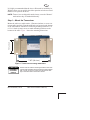
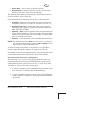
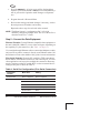
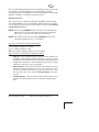
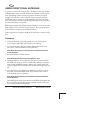
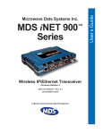
MDS iNET Series™
Wireless IP/Ethernet Transceiver
iNET-II Firmware Release 1
iNET Firmware Release 6
MDS 05-2873A01, Rev. E
MAY 2006
Installation & Start-Up
Microwave Data Systems Inc.
Refer to the Installation Reference Chart
at the middle of this manual for essential
installation and configuration details.
Contents
OPERATIONAL & SAFETY NOTICES ...................................2
PRODUCT DESCRIPTION .....................................................4
MDS CYBER SECURITY SUITE.............................................5
INSTALLATION PLANNING ....................................................6
INSTALLATION STEPS .......................................................... 6
Step 1—Mount the Transceiver ...................................................7
Step 2—Install the Antenna ........................................................8
Step 3—Measure & Connect Primary Power ..............................8
Step 4—Review the Transceiver’s Configuration ........................8
Step 5—Connect the Data Equipment ......................................10
Step 6—Check for Normal Operation .......................................11
Resetting to Factory Defaults.....................................................12
Performance Optimization .........................................................12
INSTALLATION REFERENCE CHART ............. (Center Insert)
AIMING DIRECTIONAL ANTENNAS ...................................14
TRANSMITTER POWER AND ANTENNA SWR TEST ........15
TROUBLESHOOTING ..........................................................16
SPECIFICATIONS ................................................................19
TECHNICAL ASSISTANCE & FACTORY SERVICE..............20
Copyright Notice
This publication is protected by U.S.A. copyright law. Copyright 2006, Microwave
Data Systems Inc. All rights reserved.
MDS 05-2873A01, Rev. E
iNET Series Installation & Start-Up
1
Manual Revision and Accuracy
While every reasonable effort has been made to ensure the accuracy of this manual,
product improvements may result in minor differences between the manual and the
product shipped to you. If you have questions or need an exact specification for a
product, please contact our Technical Services Team using the information at the back
of this guide. Microwave Data Systems reserves its right to correct any errors or omissions. Updated information may also be available on our Web site at www.microwavedata.com. This manual is for the use of professionals to guide them in the
installation, operation and basic system maintenance of the equipment described.
OPERATIONAL & SAFETY NOTICES
RF Exposure
Professional installation required. The radio equipment
described in this guide emits radio frequency energy.
Although the power level is low, the concentrated
energy from a directional antenna may pose a health
hazard. Do not allow people to come closer than 23 cm
(9 inches) to the antenna when the transmitter is operating in indoor or outdoor environments. More information on RF exposure is on the Internet at
www.fcc.gov/oet/info/documents/bulletins.
UL/CSA Notice
This product is available for use in Class 1, Division 2, Groups A, B, C & D Hazardous Locations. Such locations are defined in Article 500 of the National Fire Protection Association (NFPA) publication NFPA 70, otherwise known as the National
Electrical Code.
The transceiver has been recognized for use in these hazardous locations by two independent agencies —Underwriters Laboratories (UL) and the Canadian Standards
Association (CSA). The UL certification for the transceiver is as a Recognized Component for use in these hazardous locations, in accordance with UL Standard 1604.
The CSA Certification is in accordance with CSA STD C22.2 No. 213-M1987.
UL/CSA Conditions of Approval
UL/CSA Conditions of Approval: The transceiver is not acceptable as a stand-alone
unit for use in the hazardous locations described above. It must either be mounted
within another piece of equipment which is certified for hazardous locations, or
installed within guidelines, or conditions of approval, as set forth by the approving
agencies. These conditions of approval are as follows:
1. The transceiver must be mounted within a separate enclosure which is suitable for
the intended application.
2. The antenna feedline, DC power cable and interface cable must be routed through
conduit in accordance with the National Electrical Code.
3. Installation, operation and maintenance of the transceiver should be in accordance
with the transceiver's installation manual, and the National Electrical Code.
4. Tampering or replacement with non-factory components may adversely affect the
safe use of the transceiver in hazardous locations, and may void the approval.
5. A power connector with screw-type retaining screws as supplied by MDS must be
used.
2
iNET Series Installation & Start-Up
MDS 05-2873A01, Rev. E
When installed in a Class I, Div. 2, Groups A, B, C or D hazardous location, observe
the following notice: WARNING EXPLOSION HAZARD
Do not disconnect
equipment unless power has been switched off or the area is known to be non-hazardous.
6. Refer to Articles 500 through 502 of the National Electrical Code (NFPA 70) for
further information on hazardous locations and approved Division 2 wiring
methods.
Do not disconnect equipment unless power has
been switched off or the area is known to be
non-hazardous.
EXPLOSION
HAZARD!
Refer to Articles 500 through 502 of the National
Electrical Code (NFPA 70) for further information
on hazardous locations and approved Division 2
wiring methods.
FCC Part 15 Notice, U.S.A.
The transceiver described herein complies with Part 15 of the FCC Rules. Operation
is subject to the following two conditions: (1) this device may not cause harmful interference, and (2) this device must accept any interference received, including interference that may cause undesired operation. This device is specifically designed to be
used under Section 15.247 of the FCC Rules and Regulations. Any unauthorized modification or changes to this device without the express approval of Microwave Data
Systems may void the user’s authority to operate this device. Furthermore, this device
is intended to be used only when installed in accordance with the instructions outlined
in this manual. Failure to comply with these instructions may also void the user’s
authority to operate this device.
Environmental Information
The manufacture of this equipment has required the extraction and use of natural
resources. Improper disposal may contaminate the environment and present a health
risk due to hazardous substances contained within. To avoid dissemination of these
substances into our environment, and to limit the demand on natural resources, we
encourage you to use the appropriate recycling systems for disposal. These systems
will reuse or recycle most of the materials found in this equipment in a sound way.
Please contact MDS or your supplier for more information on the proper disposal of
this equipment.
About This Guide
This guide presents installation and initial operating instructions for the MDS
iNET-II™ or the MDS iNET 900™ Wireless IP/Ethernet transceiver. Following
installation, we suggest keeping this guide near the equipment for future reference.
The scope of this manual is limited to the safe and effective installation of the unit in
typical office or non-hazardous industrial settings. Users who require optimization of
the equipment’s capabilities and operating range should read the MDS iNET Series
User’s Guide, P/N 05-2806A01. This manual provides more in-depth information on
antenna selection and optimization, and extensive coverage on user-controllable
parameters and diagnostic tools.
The most essential installation information is contained on the Installation Reference
Chart found at the center of this manual.
MDS 05-2873A01, Rev. E
iNET Series Installation & Start-Up
3
PRODUCT DESCRIPTION
The MDS iNET-II and iNET transceivers are designed to provide
wireless local area network (LAN) service with plug-and-play hardware. The transceivers come in two primary models—Access Point
and Remote.
Three types of Remote Gateways are available—the Ethernet Bridge,
the Serial Gateway, and the Dual Gateway supporting both
IP/Ethernet and serial services. Table 1 summaries the different interface abilities for each type of radio.
A transceiver can be configured by the owner to operate as an Access
Point or as a Remote with some restrictions. Only the Dual Gateway
Remote units can be reconfigured as an Access Point. Ethernet Bridge
and a Serial Gateway Remotes cannot be reconfigured as Access Point
unless they are first upgraded to Dual Gateway type. This is accomplished with an “Authorization Key” purchased from the factory. Each
one of these individual software keys is associated with the serial
number of the corresponding unit.
Table 1. Transceiver Models and Data Interface Services
Model
Type
LAN1
COM11
COM2
Access Point3
N/A
Yes
Yes
Yes
Remote…
Ethernet Bridge2
Yes
No
No
Serial Gateway2
No
Yes
Yes
Dual Gateway3
Yes
Yes
Yes
NOTES
1. Provides access to the embedded Menu System on all units.
2. Can be upgraded to Dual Gateway with an Authorization Key.
3. Can be configured as an Access Point or Dual Gateway through
the embedded Menu System.
Transceivers serve as either an “Access Point” or “Remote.” An
Access Point (AP) is a wireless hub that usually provides connectivity
into a wired Ethernet LAN/WAN. From a radio perspective, an Access
Point serves as the network’s “master station” providing synchronization data to all associated Remotes (RMT) within its network.
4
iNET Series Installation & Start-Up
MDS 05-2873A01, Rev. E
Differences Between iNET and iNET-II
The iNET and iNET-II Transceivers, while similar in many respects,
do have some important differences. The main differences are summarized in Table 2:
Table 2. Transceiver Differences (iNET vs. iNET-II)
Characteristic
iNET
iNET-II
Data Rate
256/512 kbps
512 kbps/1 Mbps
FCC Certification
Type
FHSS
DTS
Encryption
RC4-128
AES-128
Channel size
316.5 kHz
600 kHz
Channel operation
Zones
Channels
Firmware
Specific for iNET
Specific for iNET-II
NOTE: The MDS iNET and MDS iNET-II transceivers are not
over-the-air compatible.
MDS CYBER SECURITY SUITE
The operation and management of an enterprise is becoming
increasing dependent on electronic information flow. An accompanying concern is the cyber security of the communication infrastructure and the security of the data itself.
The transceiver is capable of dealing with many common security
issues. Table 3 profiles security risks and how the transceiver provides
a solution for minimizing vulnerability. In all cases, the Security Configuration Menu should be reviewed and set to the required parameters
for your environment. Please refer to the User’s Guide (05-2806A01)
for complete information.
MDS 05-2873A01, Rev. E
iNET Series Installation & Start-Up
5
Table 3. Cyber Security Highlights
Security Level
Specification
• MDS Cyber Security
Suite, Level 1:
• AES-128 encryption (iNET-II only)
• Includes Level 2 features below
• MDS Cyber Security
Suite, Level 2:
• RC4-128 encryption (iNET only)
• Automatic rotating key algorithm
• Authentication: 802.1x, RADIUS, EAP/TLS, PKI,
PAP, CHAP
• Management: SSL, SSH, HTTPS
• Approved AP/Remotes list (local authentication)
• Failed login lockdown
• 900 MHz operation and proprietary data framing
INSTALLATION PLANNING
This section provides tips for installation and start-up of the equipment.
General Requirements
There are three main requirements for installing the transceiver—adequate and stable primary power, a good antenna system, and the correct interface between the transceiver and the data device. The
Installation Reference Chart (center of this guide) shows a typical
Remote installation. Access Point stations typically use omnidirectional antennas whereas Remotes typically use directional antennas
such as a Yagi. Otherwise, the installations are similar.
INSTALLATION STEPS
A typical product shipment consists of a transceiver, a power connector and this start-up guide.
Below are the basic steps for installing a transceiver. Should further
information be needed, see “TECHNICAL ASSISTANCE” on Page
20 of this manual for information on contacting the MDS Technical
Services Group. You will also find support information at the Microwave Data Systems Web site: www.microwavedata.com.
6
iNET Series Installation & Start-Up
MDS 05-2873A01, Rev. E
It is highly recommended that the Access Point unit be installed first.
With this plan, you can quickly check the operation of each associated
Remote as it is placed on the air.
NOTE: Transceivers are shipped from the factory set to the “Remote”
mode unless they are marked differently.
Step 1—Mount the Transceiver
Mount the radio to a stable surface. (Fasteners/anchors or screws are
not normally supplied.) Four threaded holes are located on the bottom
of the radio that are suitable for connecting mounting hardware. Use
6-32 x 1/4 inch (6 mm) screws to attach mounting hardware to the
bottom of the radio. Figure 1 shows the mounting dimensions.
Invisible place holder
2.75˝ (7 cm)
7.25˝ (18.4 cm)
Figure 1. Transceiver mounting dimensions
CAUTION
POSSIBLE
EQUIPMENT
DAMAGE
Screws used to hold the mounting brackets to the radio
case should be SAE 6-32 and should not extend farther
than 1/4 inch (6 mm) into case. This will prevent damage to the transceiver’s internal PC board.
MDS 05-2873A01, Rev. E
iNET Series Installation & Start-Up
7
Step 2—Install the Antenna
To minimize radio frequency interference, the antenna should be
mounted at least nine inches (> 23 cm) from the connected device(s),
sensors and other components of the system. Additional information
on antenna selection and installation is provided in the
MDS iNET Series User’s Guide.
Step 3—Measure & Connect Primary Power
The primary power at the transceiver’s power connector must be
within 10.5–30 Vdc and be capable of continuously providing up to
580 mA. A power connector with screw-terminals is provided with
each unit. Strip the wire leads to 6 mm (0.25"). Be sure to observe
proper polarity as shown in Figure 1 with the positive lead (+) on the
left. If the transceiver is to be powered at voltages of 28 Vdc or higher,
please review the User’s Guide for important recommendations.
Invisibleplaceholder
Lead
Binding
Screws (2)
+–
Wire Ports
Figure 2. Power Connector
Polarity: Left +, Right –
CAUTION
POSSIBLE
EQUIPMENT
DAMAGE
The transceiver must be used only with negative-ground
systems. Make sure the polarity of the power source is
correct. Review complete power requirements in the
User’s Guide, Part No. 05-2806A01.
The power supply used with the transceiver should be equipped with
overload protection (NEC Class 2 rating), to protect against a short circuit between its output terminals and the transceiver power connector.
NOTE: It typically takes about 30 seconds for the transceiver to power
up, and about 20 to associate with another unit.
Step 4—Review the Transceiver’s Configuration
Two essential settings for the transceiver should be known before
placing the unit into service. They are:
8
iNET Series Installation & Start-Up
MDS 05-2873A01, Rev. E
• Device Mode—Access Point, or Remote (default).
• Network Name—Common identifier used by all of the units,
which are part of the same network (required).
The Network Name must be programmed to enable Remote units to
associate with the Access Point unit.
Other parameters that commonly need review or adjustment are:
• IP Address—Must be a unique address to allow for IP access
through the LAN port or over-the-air. (Default = 192.168.1.1)
• RF Output Power Level—Check and adjust as necessary for
compliance with regulatory guidelines. (Defaults: iNET=+30
dBm, iNET-II=+28 dBm.)
• Data Rate—AUTO selection (default) allows maximum data rate
for the current signal level. (The stronger the signal, the higher
the data rate.) iNET-II data rates are 512 kbps or 1 Mbps; iNET
rates are 256 kbps or 512 kbps.
• Password—Used for remote access and Menu System features.
NOTE: The default password is admin. For web access, a username is
also required. The default username is iNET or iNET-II in accordance with the radio model being used.
A unique IP address and subnet are required to access the Menu
System, either through the LAN port, or remotely over-the-air.
A summary of selected operating parameters’ range and default values
is included in the Reference Chart at the center of this booklet.
How to Review the Transceiver’s Configuration
The following is an overview of the configuration procedure. For
detailed instructions on using the HTTP (LAN Port) and text-based
(COM1) Menu System, please refer to the User’s Guide. Key menu
selections are shown at the center of this guide.
a. Connect a computer’s serial communications port to the COM1
Port. (Defaults: 19,200 bps/8N1/No Handshaking)
b. Launch a terminal emulator program, such as HyperTerminal,
on the computer. Configure to: 19,200 bps/8N1/no handshaking/VT100.
MDS 05-2873A01, Rev. E
iNET Series Installation & Start-Up
9
c. Press the ENTER key. A login screen will be displayed that
requires a password (default = admin) to access the Menu System. A password is required to make changes to all parameters.
d. Program the radio’s Network Name.
e. Review other settings and make changes if necessary, such as
the unit password, IP address and security.
Repeat the above steps for each unit in the network.
NOTE: The Menu System’s “configuration files” will aid in
uniformly configuring multiple units. The use of these files is
described in the User’s Guide.
Step 5—Connect the Data Equipment
Ethernet Example: Connect Ethernet-compatible data equipment to
the unit’s LAN port (10BaseT), or one of the serial ports, depending on
the capability of your transceiver. (See Table 1 on Page 4.)
Use a straight-through Ethernet cable to connect the LAN port to a hub,
and a crossover cable to connect it directly to an Ethernet station. See
the Reference Chart at the middle of this guide for more information.
IP-to-Serial Example: From the PC, establish a TCP connection to
the IP address of the Remote transceiver and to the IP port. A Telnet
client application can be used to establish this connection. Data may
now be sent between the PC and the RTU or other connected device.
Configure the port as shown in Table 4.
Table 4. Serial Port Configuration (IP-to-Serial Connection)
Transceiver
Location
Menu Item
Setting
Access Point
None is required
None is required
Remote Unit
IP Address
192.168.0.2
Status
Enabled
IP Protocol
TCP
Baud Rate
9,600 (Example)
Flow Control
None
Local IP Port
30011
10
iNET Series Installation & Start-Up
MDS 05-2873A01, Rev. E
Step 6—Check for Normal Operation
In this step you will verify the proper operation of wireless communications between an Access Point and the associated Remotes.
At All Units...
Observe the transceiver’s LED panel (See Reference Chart) for the
proper indications. In a normally operating system, the radio will usually become associated in less than one minute from start-up.
At the Access Point Unit...
a. If the Access Point unit is the first unit you are installing, send
a PING command to it through the LAN port. This verifies basic
LAN connectivity.
b. If you have already installed a Remote unit, try sending a PING
to that unit through the Menu System PING utility.
At Remote Units...
a. Look for the LINK LED to turn on and remain on. This indicates the unit has successfully associated with the network’s
Access Point. (The association process may take up to 30 seconds.)
b. Check the Starting Information screen for the Device Status
(also known as Connection Status). It will show one of the following:
Scanning—The
unit is looking for an Access Point beacon signal.
Exp(ecting) Sync(hronization)—The
unit has found a valid beacon
signal for its network.
Hop Sync—The
unit has changed its frequency hopping pattern to
match that of the Access Point.
Connected —The
unit has a radio (RF) connection with the Access
Point, but has not obtained cyber-security clearance to pass data.
—This unit has successfully synchronized and associated
with an Access Point. This is the normal status.
Associated
Alarmed—The
unit is has detected one or more alarms that have not
been cleared.
MDS 05-2873A01, Rev. E
iNET Series Installation & Start-Up
11
c. When the network is operating properly based on observation
of the unit’s LEDs, connect a computer to the transceiver’s
data port that will be used by the local terminal equipment.
Send the PING command to verify the communications link
integrity with the Access Point.
d. After the PING command is successful, connect the terminal
equipment to the radio’s data port and verify normal operation.
If all checks are OK, you are finished with the installation at this site.
Resetting to Factory Defaults (Use with Care)
This procedure may be useful when several parameters have been
modified, and there is no track of changes. It causes the transceiver to
return to a known-operational state.
To reset all transceiver parameters back to the factory defaults,
including the password (default = admin), you must enter a special
code (authorization key) provided by the factory in place of the user
name at the time of login. Contact the factory for more information.
Performance Optimization
After the basic operation of the network has been verified, you may
wish to optimize its performance using the suggestions given below.
The effectiveness of these techniques will vary with the amount of
data being handled.
Optimize Received Signal Strength
Check the received signal strength indicator (RSSI) for an adequate
signal level from the radio network’s Access Point. (RSSI is available
through the Menu System.) In the absence of interference, signal
levels that are sufficient to provide reliable operation (with a 15 dB
fade margin) are: ≥ –84 dBm @ 256 kbps, ≥ –75 dBm @ 512 kbps ≥
–65 dBm @ 1 Mbps.
If the signal levels are lower, it may be necessary to reposition the station’s antenna for better reception/signal strength.
Minimize Packet Retries
If the Wireless Packet Statistics’ retry packet counter is unacceptably
high, several techniques can be used to improve it.
12
iNET Series Installation & Start-Up
MDS 05-2873A01, Rev. E
These include identifying interference and taking corrective steps such
as skipping some radio frequencies from the hopping pattern,
increasing the gain of the Remote unit’s antenna system, relocating the
Remote’s antenna, or installing a repeater system.
Blocking Out Zones
The transceiver uses channels in the 902–928 MHz spectrum, with
selectable hopping from 1 to 80 channels. This selection is available
only on iNET-II or specially provisioned iNET units using the Channel
Config(uration) Submenu.
NOTE: When using CHANNELS mode, all radios (AP and Remotes)
must be set to use the same channels in order to establish a
link. If this is not done, the radios will not connect.
NOTE: The iNET-II operates only in the CHANNELS mode, with
selectable hopping from 1 to 75 channels.
Usage key for Channel Configuration Menu:
n (no) = Radio channel is not used
y (yes) = Radio channel is used
NA (not available) = Radio channel
is not available
Other selections on Channel Configuration Menu:
• Clear All—This command clears all entries in the Channel Config Menu, resetting the available channels to “no usage.” Channels that are not available for use will appear with a notation of
or NA. These channels are not available because of pre-existing
conditions, and are not user-configurable.
• Enter Channels—This allows selection of the channels used for
frequency hopping operation. The selection of particular channels will result in an indication of y. Be aware that these channels do not become active until the Commit Changes selection is
invoked.
• Commit Changes—This re-boots the radio and loads the active
channels into the frequency list for frequency hopping operation.
MDS 05-2873A01, Rev. E
iNET Series Installation & Start-Up
13
AIMING DIRECTIONAL ANTENNAS
In general, signal levels stronger than –80 dBm will provide reliable
communication in the network. Directional antennas usually require
some fine-tuning of their bearing to optimize the received signal
strength. The unit has a built-in received signal strength indicator
(RSSI) that can be used as an aid to optimizing the received signal
level. The measurement and antenna alignment process usually takes
less than 10 minutes at each unit.
RSSI measurements and Wireless Packet Statistics are based on multiple samples over a period of several seconds. The average of these
measurements is displayed by the Menu System.
In the steps below, the path to the Menu System item is shown in bold
text.
Procedure
1. Verify the Remote is associated with an Access Point unit by
observing the LINK LED. It should be on or blinking.
2. View and record the Wireless Packets Dropped and Received
Error rates. This information will be used later.
Main Menu>Performance Information>Packet Statistics>Wireless
Packet Statistics
3. Read the RSSI level at the Remote.
Main Menu>Performance Information>RSSI by Zone
4. Optimize RSSI by slowly adjusting direction of antenna. Watch
the RSSI indication for several seconds after making each adjustment so that the RSSI accurately reflects any change in the link
signal strength. The less negative the number, the stronger the signal.
5. View the Wireless Packets Dropped and Received Error rates at
the point of maximum RSSI level. They should be the same or
lower than the previous reading.
Main Menu>Performance Information>Packet Statistics>Wireless
Packet Statistics
If the RSSI peak results in an increase in the Packets Dropped and
Received Error, the antenna may be aimed at an undesired signal.
Try a different antenna orientation.
14
iNET Series Installation & Start-Up
MDS 05-2873A01, Rev. E
TRANSMITTER POWER AND ANTENNA
SWR TEST
The following procedure may be used to measure the transmitter’s RF
power output and SWR “match” of the antenna system. A directional
wattmeter is required for the test, such as a Bird Model 43, with an
appropriate element installed.
Before you start, keep in mind that using the Test Mode will disrupt
network operation.
Procedure
1. Connect a directional wattmeter between the ANTENNA port and
the antenna system.
2. Place the transceiver into the Radio Test Mode.
Main Menu>Maintenance/Tools Menu>Radio Test>Test Mode>Y>ON
NOTE: The Test Mode has a 10-minute timer, after which it will
return the transceiver to normal operation. The Test Mode can also
be terminated manually, via the menu.
3. Set the transmitter RF output power to 30 dBm.
Main Menu>Maintenance/Tools Menu>Radio Test>Test Mode>
Tx Power Output
NOTE: The Test Mode RF power setting will not affect the output
level during normal operation.
4. Turn on (key) the transmitter.
Main Menu>Maintenance/Tools Menu>Radio Test>Test Mode>
TxKey> Enable
User the spacebar to key and unkey the transmitter ON and OFF.
(Enable/Disable)
5. Measure the forward and reflected power into the antenna system
and calculate the SWR. The ratio should be less than 2:1. The
power output level should agree with the programmed value set in
Step 3.
Main Menu>Radio Configuration>RF Power Output
6. Turn off Test Mode at the Access Point and Remote radio.
Main Menu>Maintenance/Tools Menu>Radio Test>Test Mode>Disable
MDS 05-2873A01, Rev. E
iNET Series Installation & Start-Up
15
TROUBLESHOOTING
It is best to begin troubleshooting at the Access Point, because the rest
of the system depends on it for network synchronization and configuration. If the Access Point has problems, the operation of the entire
network will be affected.
All radios in the network must meet these basic requirements:
• Adequate and stable primary power
• An efficient and properly aligned antenna system
• Secure connections (RF, data & power)
• Proper programming of the unit’s operating parameters, especially Device Mode selection (Access Point/Remote), Network
Name, and IP Address
• The correct interface between the radio and the connected data
equipment (proper cable wiring, data format and timing)
Table 5 provides suggestions for resolving common system difficulties using the front panel LEDs as a guide. Table 6 on Page 17 provides guidance using the Menu System as a tool.
If problems persist, review the MDS Web site’s technical support area
for general troubleshooting help, service information, and recent software/firmware updates at www.microwavedata.com/service/
technical/support/. Additional help is available from the MDS Technical Services Department. See “TECHNICAL ASSISTANCE” on
Page 20 for contact information.
Table 5. Troubleshooting Using LEDs
Symptom
Problem/Recommended Checks
PWR LED
does not
light.
a. Voltage too low—Check for proper supply voltage at
the power connector (10.5–30 Vdc).
PWR LED is
blinking.
a. Blinking indicates the presence of an alarm condition.
b. Indefinite Problem—Cycle the power and wait
(≈ 30 seconds) for the unit to reboot. Then, recheck for
normal operation.
b. View Current Alarm List and Error Log and correct the
problem if possible.
c. Blinking continues until the fault is corrected, for
example, a valid IP address is entered, etc.
16
iNET Series Installation & Start-Up
MDS 05-2873A01, Rev. E
Table 5. Troubleshooting Using LEDs (Continued)
Symptom
Problem/Recommended Checks
LINK LED
does not
light.
a. Network Name of Remote not identical to desired
Access Point—Verify that the system has a unique
Network Name.
b. Not yet associated with an Access Point with the same
Network Name.
Check the “Status” of the unit’s process of associating
with the Access Point. Use the Menu System.
c. Poor Antenna System—Check the antenna, feedline
and connectors. Reflected power should be less than
10% of the forward power reading (SWR 2:1 or lower).
LAN LED
does not turn
on.
a. Verify the Ethernet cable is connect at both ends.
b. Verify that the appropriate type of Ethernet cable is
used: straight-through, or crossover as required.
Table 6. Troubleshooting with the Menu System
Symptom
Problem/Recommended System Checks
Remote does not
associate; stays in
HOPSYNC
a. Verify the AP has sufficiently large number in the
“Max Remotes” parameter of the Network
Configuration Menu.
b. Verify the correct MAC address is listed in the
“Approved Remotes List” or “Approved Access
Points List” of the Security Configuration menu.
Serial data is slow
with UDP multicast
traffic
a. Change Beacon Period to FAST.
(Radio Configuration Menu)
Display on
terminal/Telnet
screen garbled
a. Verify the terminal/terminal emulator or Telnet
application is set to VT100
MDS 05-2873A01, Rev. E
iNET Series Installation & Start-Up
17
Table 6. Troubleshooting with the Menu System
Symptom
Problem/Recommended System Checks
Cannot access the
MS through COM1
a. Connect to unit via Telnet or Web browser
b. Disable the serial mode for COM1
(Serial Gateway Configuration>Com1 Serial
Data Port>Status>Disabled)
or, if you know the unit’s data configuration...
c. Connect to COM 1 via a terminal set to VT100
and the port’s data baud rate.
d. Type “+++ [ENTER]”
e. Change the terminal’s baud rate to match the
transceiver’s Console Baud Rate.
f. Type “+++ [ENTER]”
Cannot pass IP
data to WAN.
a. Verify your IP settings.
b. Use the PING command to test communication
with units in the local radio system.
c. If successful with local PING, attempt to PING an
IP unit attached to another radio.
d. If successful with the LAN PINGs, try connecting
to a known unit in the WAN.
Wireless Retries
too high.
Possible Radio Frequency Interference—
a. If omnidirectional antennas are used, consider
changing to directional antennas. This will often
limit interference to and from other stations.
b. Try skipping zones where persistent interference
is known or suspected.
c. The installation of a filter in the antenna feedline
may be necessary. Consult the factory for further
assistance.
Password
forgotten.
a. Connect to the unit using a terminal through the
COM1 Port.
b. Consult the factory. Get a password-resetting
Authorization Key.
c. Enter the Authorization Key at the login prompt
as a password.
18
iNET Series Installation & Start-Up
MDS 05-2873A01, Rev. E
SPECIFICATIONS
GENERAL
Temperature Range:
Humidity:
Primary Power:
External Power Supply Options:
Supply Current (typical):
Transmit:
Receive:
Size (Excluding mtg. hardware):
Weight:
Case:
–30° C to +60° C (–22° F to 140° F)
95% at +40° C (104° F); non-condensing
10.5–30 Vdc (13.8 Vdc, Nominal)
48 Vdc; 110–120/210–220 Vac
(@ 1 Watt RF Output)
8 Watts (580 mA @ 13.8 Vdc)
2.8 Watts (203 mA @ 13.8 Vdc)
1.5" x 6" x 4" (H x W x D)
3.8 x 15.2 x 10.2 cm
0.9 kg / 2 lb
Cast Aluminum
RADIO CHARACTERISTICS
GENERAL:
Frequency Range:
Mode:
Boot Time:
Time Required to Associate
with Access Point:
TRANSMITTER:
Power Output
(at antenna connector):
902–928 MHz Industrial, Scientific &
Medical (ISM) Band
Freq. Hopping Spread-Spectrum (FHSS)
≈ 30 sec
≈ 20 sec
Duty Cycle:
Output Impedance:
0.1 to 1.0 watt (+20 dBm to +30 dBm)
Increments of 1.0 dB, set by user
Continuous
50 Ohms
RECEIVER:
Type:
Double conversion superheterodyne
Sensitivity (< 1x10⁻⁶ BER):
MDS 05-2873A01, Rev. E
iNET: –92 dBm @ 512 kbps
iNET: –99 dBm @ 256 kbps
iNET-II: -92 dBm @ 1 Mbps
iNET-II: -97 dBm @ 512 kbps
iNET Series Installation & Start-Up
19
TECHNICAL ASSISTANCE
Technical assistance for MDS products is available from our Technical Support Department during business hours (8:00 A.M.–5:30
P.M. Eastern Time). When calling, please give the complete model
number of the radio, along with a description of the trouble
symptom(s) that you are experiencing. In many cases, problems can be
resolved over the telephone, without the need for returning the unit to
the factory.
Phone: 585 241-5510
E-Mail: [email protected]
FAX: 585 242-8369
Web: www.microwavedata.com
FACTORY SERVICE
If return of the equipment is necessary, please contact the MDS Technical Support Team. You will be issued a Service Request Order
(SRO) number. The SRO number will help expedite the repair so that
the equipment can be repaired and returned to you as quickly as possible. Please be sure to include the SRO number on the outside of the
shipping box, and on any correspondence relating to the repair. No
equipment will be accepted for repair without an SRO number.
A statement should accompany the radio describing, in detail, the
trouble symptom(s), and a description of any associated equipment
normally connected to the radio. It is also important to include the
name and telephone number of a person in your organization who can
be contacted if additional information is required.
The radio must be properly packed for return to the factory. The original shipping container and packaging materials should be used whenever possible. All factory returns should be addressed to:
Microwave Data Systems Inc.
Customer Service Department
(SRO No. XXXX)
175 Science Parkway
Rochester, NY 14620 USA
When repairs have been completed, the equipment will be returned to you by
the same shipping method used to send it to the factory. Please specify if you
wish to make different shipping arrangements. To inquire about an in-process
repair, you may contact our Product Services Group at 585-241-5540 (FAX:
585-242-8400), or via e-mail at [email protected].
20
iNET Series Installation & Start-Up
MDS 05-2873A01, Rev. E
Installation Guide
Microwave Data Systems Inc.
175 Science Parkway
Rochester, NY 14620
General Business: +1 585 242-9600
FAX: +1 585 242-9620
Web: www.microwavedata.com
A product of Microwave Data Systems Inc.