1
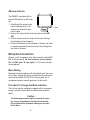
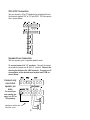
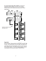
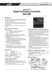
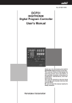
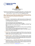
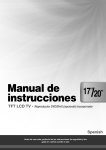
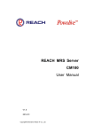
Digital FM/AM Receiver
Model RM-350D
User’s Guide
54-5021-01
9609
Printed in USA
Specifications
Band Coverage . . . . . . . . . . . .
AM . . . . . . . . . . . . . . . . . . . . .530 - 1620KHz
FM . . . . . . . . . . . . . . . . . . . . . .87.5 - 107.9MHz
Tuning . . . . . . . . . . . . . . . . . . . .PLL Synthesizer
Channel Indicator . . . . . . . . . . .LCD panel
Memory Presets . . . . . . . . . . . .18 - FM; 12 - AM
Memory Scan . . . . . . . . . . . . . .Preset stations
Power Rating (RMS) . . . . . . . . .35W
Audio Frequency Response . .20Hz to 20KHz Direct
70Hz to 15KHz Transformer
Audio Sensitivity . . . . . . . . . . .Aux - 80mV; Lo-Z Mic - 750µV
Microphone Input . . . . . . . . . . .Balanced Lo-Z; XLR-312C
Aux Input . . . . . . . . . . . . . . . . .RCA jack accepts signal from
CD, tape deck or other linelevel source
Pre Page Output . . . . . . . . . . . .RCA Jack
Tape Output . . . . . . . . . . . . . . .RCA Jack
Output Taps . . . . . . . . . . . . . . .4/8Ω, 25V, 70V
ALC . . . . . . . . . . . . . . . . . . . . .Switch selected
Mic Precedence . . . . . . . . . . . .Dry contact (normally open)
Internal jumper selects normally
open/normally closed
Speaker Zones . . . . . . . . . . . . .Selected by pushbuttons
4 individual plus 1 All Call
Program Selection . . . . . . . . . .Pushbutton
Antenna Connectors . . . . . . . .FM - 75Ω, 300Ω, AM
AC Power Required . . . . . . . . .120VAC nominal @ 60Hz, 98W
Dimensions . . . . . . . . . . . . . . .12.05” x 8.46” x 3.43”
Shipping Weight . . . . . . . . . . . .13 lbs., 2 oz.
Accessories Included . . . . . . .AM Loop , FM Dipole,
Mono Patch Cord
Rack Kit Available . . . . . . . . . .Model RPK47
2
Before You Begin
Your Bogen RM-350D Digital Tuner/Receiver incorporates the
latest in PLL digital circuitry for reliable performance for years to
come. To get the maximum benefit from your Bogen product,
please read all instructional materials provided with the unit.
Unpacking
The RM-350D is carefully checked before leaving the factory.
Inspect the shipping carton and unit for damage caused by
improper handling. If damage is found you must file a claim
with the transportation company that delivered the product.
Warning
To Prevent Fire or Shock Hazard, Do Not
Expose This Appliance to Rain or Moisture.
Make all connections with the power OFF
Antenna Connection
FM Dipole Antenna
The indoor dipole antenna provided should be adequate for normal FM reception.
1. Connect the antenna leads to the two terminals marked 300
OHM BAL.
2. Move the antenna around to determine the best reception;
tack it to a wall or baseboard, if possible.
For reception where the unit is installed in a rack, an external
antenna installed in accordance with National Electric Codes, is
required. Either:
a) Connect the external antenna leads to the 300 OHM BAL
terminals.
b) For applications using coaxial cable, a 75 OHM coaxial
cable connector is provided.
3
AM Loop Antenna
The RM350D is provided with an
external AM antenna for AM reception.
1. Carefully pull the antenna lead
from the holding notch in the
antenna and unwind the lead
from the loop.
2. Connect the antenna leads to the terminals marked AM
ANT.
3. Fold the antenna so that it snaps into the base forming a
free-standing unit (see diagram).
4. Position the antenna for best reception. If desired, the antenna may be permanently mounted using screws through the
two holes in the base.
Microphone Connection
Connect a Lo-Z microphone to the 3-pin connector marked MIC
BAL on the rear panel. Be sure to observe correct polarity:
Pin 1 is GND, pins 2 & 3 are signal. A VOX circuit activates
the microphone.
Music Muting
Speaking into the microphone will automatically mute the aux or
tuner output. Muting can also be accomplished by shorting the
two terminals labeled AUX MUTE on the rear panel with a
microphone having a normally open push to talk switch.
Procedure To Change Aux Mute Activation
The unit may also be configured to operate with a microphone
having a normally closed switch by following the procedure
below:
Caution
The following procedure requires removal of protective covers, presenting an electrical shock hazard.
Do not perform this procedure unless you are qualified to do so.
4
1. Unplug the unit from electrical source.
2. Remove eight (8) screws securing the unit cover to the
chassis.
3. Slide cover back to remove it from chassis.
4. Locate Jumper J1 on the circuit board (right side of the unit
as you look at it from front panel).
5. Reposition jumper from CLOSED position to OPEN position.
6. Reinstall cover and screws.
Microphone ALC (Automatic Level Control)
An ALC switch on the rear panel controls the ALC circuit. When
“ON,” the ALC will maintain a consistent level between various microphone users
AUX Input
Connect an Aux source to the RCA jacked marked AUX.
PREPAGE OUT
The prepage output lets you route tuner and auxiliary input to a
telephone music-on-hold input. The output is also independent
of the tone and volume controls.
Speaker Connections
Ω Direct Connection
4-8Ω
You can connect a 4-8Ω speaker to the terminals marked 4-8Ω
Ω unbaland GND as shown below. Remove the LINK for 4-8Ω
anced output.
5
25V & 70V Connection
You can connect a 25 or 70V balanced or unbalanced line to
the terminals marked 25V or 70V and GND. 25V line connection is shown below.
Speaker Zone Connection
You can connect up to 4 separate speaker zones.
Ω speakers: Connect the impedTo connect zones of 4 - 8Ω
ance selector jumper wire to the 4-8Ω terminal. Remove the
shorting bar between the LINK terminals. Connect one 8ohm speaker to the desired zone terminal and COM, as
shown below.
Connect only
one 8-ohm
speaker per
zone.
For more than
one speaker per
zone, use 25V or
70V speakers.
Impedance selector wire
from back of unit.
6
To connect zones using 25V or 70V line: Connect the
impedance selector jumper to the 25V or 70V terminal.
Connect the line to the desired zone terminal and COM as
shown below.
Impedance selector wire
from back of unit.
Tape Out
You can connect a tape recorder to the RM350D using the Tape
Out jack. This jack provides a line level output consisting of the
signal being sent to the loudspeakers, that can also be used to
drive another amplifier. All controls affect this output. Connect
a mono patch cord to the jack marked TAPE/BOOSTER
7
Operation
Power
Press the front panel POWER switch to apply power. Adjust
the volume to the appropriate level using the amplifier volume
control.
To Select a Band
Press the button marked BAND. The current band appears on
the display: FM1, FM2, FM3, AM1 or AM2.
You can preset up to six stations on each band for a total of 30
preset stations (18 FM and 12 AM).
To Tune a Station
Press the UP or DOWN buttons.
To Preset Stations
1. Select a band and tune the first desired station.
2. Press one of the “M” buttons; for example, M1 (The preset
number appears on the display as CH1).
3. Continue pressing the “M” button until the program material
from the speaker stops for a second and then resumes.
This indicates that the preset is stored.
4. Tune the next station and repeat Steps 2 & 3 for the 2nd
through 6th preset.
To Scan Preset Stations
1. Select a band. The first preset station (CH1) will appear on
the display.
2. Press the button marked MSCAN. Each preset station will
play for 5 seconds in turn while scanning.
3. To stop the scanning, press the “MSCAN” button again.
Program Selection
Use the AUX/TUNER button to select program from the tuner or
aux source. Push in for Aux program. Push out for Tuner program
8
Microphone Volume
Use the MICROPHONE control to adjust mic volume.
Aux/Tuner Volume
The VOLUME control adjusts the output level of program from
tuner and aux sources. It does not control the level of the
microphone program.
Tone Controls
Use the BASS and TREBLE controls to adjust tonal balance of
program from the tuner, microphone and Aux sources.
Speaker Zone Selection
Use the selector buttons labeled 1 - 4 to turn the output on or
off for each zone. Use the ALL button to supply output to all
zones, overriding individual selection buttons
9
Maintenance
CAUTION
There are no user serviceable parts within the tuner.
To avoid an electric shock hazard, refer all internal
servicing to qualified service personnel only.
The warranty will become void if repairs are made by
other than the Bogen Factory Service Center.
We are interested in the maintenance of your Bogen equipment.
In the event of any difficulty, do not hesitate to ask our advice or
assistance. Information may be obtained by writing to the
Service Department, Bogen Communications, Inc., P.O. Box
575, Ramsey, NJ 07446.
When communicating with us, please give the model number of
your unit. Describe the difficulty encountered and include details
on the electrical connections to associated equipment.
For warranty and repair information, please refer to the warranty
registration card included with the unit.
10
50 Spring Street, Ramsey, NJ 07446
(201) 934-8500 Fax: (201) 934-9832