1
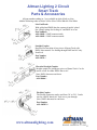
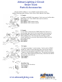
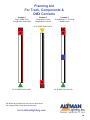
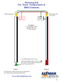
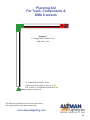
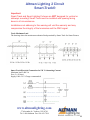
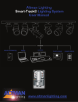
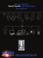
Altman Lighting Smart-Track® Lighting System User Manual www.altmanlighting.com Altman Lighting 2 Circuit Smart Track Table of Contents Smart Track Introduction 3 Smart Track Part and Accessories 4 Smart Track Planning Aid 9 Smart Track Lighting & Track Specifications 16 Safety & Installation Instructions 17 Smart Track LED Fixture Settings 18 Smart Track Quartz & HID Settings 21 Smart Track Fixture Installation 22 Smart Track Maximum Weight Loads 23 Smart Track 120 V AC Wiring 23 Smart Track Fixture RDM Features 24 RAD (Remote Authorization Device) 26 www.altmanlighting.com 57 Alexander St., Yonkers, NY 10701 Tel: 1-800-4Altman Fax: 914-963-7304 2 Altman Lighting 2 Circuit Smart Track Introduction Smart Track Altman Architectural/ Theatrical Smart Track Lighting Systems is a revolutionary way to bring digital control signals to addressable architectural/ theatrical lumanaires without the need for dimmer packs and bulky cable runs. Altman Smart Track is easy to lay out, install and offers lighting professionals the opportunity to easily create and activate new lighting scenes time after time. The Smart Track Lighting System works in conjunction with Altman Smart Track lumanaires; from the IQ Series, a family of pars, UV, LED and wall washers; the Master & Micro Series of pars and ellipsoidals, and select Theatrical fixtures. Quartz, CDM, low voltage and LED selections are available in both Smart to Non-Smart versions of various types. Smart units have an addressable DMX dimmer for quartz units, a DMX on/off relay for CDM and on board power supply and DMX interface for LED lighting units. Non-Smart units work via direct power and cannot be addressed or controlled. With Smart Track you can dim individual quartz lamps; switch the CDM lamps on and off; as well as dim and color mix LED sources. The unique features and capabilities of Altman Smart Track make it the ideal solution for many applications. The system is suitable for retail stores, museums, churches, restaurants, theme parks, night clubs and much more. The range of applications for Altman Smart Track is as varied as the looks the system makes possible. Altman Smart Track is a comprehensive system of components that offers innovative soloutions for transporting control signals as well as power to individual lumanaires. Whether using simple architectural stations; a laptop; or a DMX based theatrical lighting console, the lighting professionals are always in control with Smart Track. The heavy duty extruded aluminum track is ideal for demanding applications where a low profile look is desired but numerous lumanaires are required. The Altman Smart luminaires retain their identity and programming, even when moved to new location on the track. Automated luminaires as well as other DMX luminaires and accessories may be controlled from the Altman Smart Track by using a Smart Track DMX convenience adapter. AC convenience adapters are also available. Non DMX luminaires can be controlled via the Smart Box, a Smart 600 watt maximum load addressable dimmer with a receptacle for powering and dimming from the track. Support for these types of fixtures is independent from the track. For total flexibility, you can choose your protocol. Smart Track is compatible with DMX and RDM (Remote Devise Management). It can also be integrated into existing systems to easily expand new designs. By incorporating the digital control signal into the track, the Smart Track system allows dimming, switching and effects to be obtained when using any of the numerous compatible Altman lumanaires. With the quartz and CDM luminaires with on board control as well as Altman Spectra series luminaires for color mixing, the lighting potentials are endless. www.altmanlighting.com 3 Altman Lighting 2 Circuit Smart Track Parts & Accessories All part numbers ending in -* are available in white, black or silver. Add the following codes to finish: 3-1 for Silver 2-2 for Black 1-3 for White Smart Track 2 Circuit/ 2 Neutral surface track with DMX/ data bus offers the ability to control individual Altman Lighting luminaries with addressable on board DMX dimmers, HID on/ off relay or LED color changers. Part numbers ASL-23310-* 4’ Section 2 Circuit Smart Track ASL-23320-* 8’ Section 2 Circuit Smart Track ASL-23330-* 12’ Section 2 Circuit Smart Track Smart Track Features Color and finish The track is available in black or white powder coat or silver anodized. All system components and adapters are available in white, black or painted finish. Easy to cut on site Any given profile can be easily cut to length on site. It is not necessary to cut back and bend back copper wire. Mounting Points The track has pre-punched holes 1/4” (6mm) x 3/8” (35mm) for surface mounting. The holes are spaced 8”on center and can be easily pushed out using a screwdriver. www.altmanlighting.com 4 Altman Lighting 2 Circuit Smart Track Parts & Accessories All part numbers ending in -* are available in white, black or silver. Add the following codes to finish: 3-1 for Silver 2-2 for Black 1-3 for White Live End Feeds With gold plated DMX/data bus contacts & nickel plated line voltage springs for feeding AC and DMX in or out. Part Numbers ASL-99802-* DMX contacts inside ASL-99803-* DMX contacts outside Straight Coupler Recessed, for butt joint of two pieces of Smart Track with DMX/ data contacts. For feeding through DMX and AC only. Non-Feed Part Number ASL-99874-* Electrical Straight Coupler Straight coupler for joining two pieces of Smart Track. Can be used as a feed for either DMX/ data or AC. Note: DMX/ data must run linear. Part Number ASL-99806-* Flexible Coupler . The flexible connector can be used from 30° to 330°. Can be used as a DMX/ data & AC feed or as a pass through. Note: DMX/ data must be run linear. Part Number ASL-985812-* www.altmanlighting.com 5 Altman Lighting 2 Circuit Smart Track Parts & Accessories All part numbers ending in -* are available in white, black or silver. Add the following codes to finish: 3-1 for Silver 2-2 for Black 1-3 for White L Coupler L-Coupler with DMX/ data contacts. Can be uses as a feed for either DMX/ data or AC. Note: DMX/ data must be run linear. Part Numbers ASL-99809-* DMX contacts inside ASL-99810-* DMX contacts outside X-Coupler 4 x 90° Joiner. Can be used as a DMX/ data & AC feed or as a pass through. Note: Special care must be taken when laying out and wiring DMX/ data in and out of the X-Coupler to keep the DMX running linear. This means breaks inside the X on the control signal may be necessary. More then one DMX/ data line may need to be run. Part Number ASL-99816-* T-Coupler T-Coupler for joining 3 x track sections. Can be used as a DMX/ data & AC feed or as a pass through. Note: Special care must be taken when laying out and wiring DMX/ data in and out of the TCoupler to keep the DMX running linear. This means breaks inside the T on the control signal may be necessary. More then one DMX/ data line may need to be run. Part Number ASL-99814-* Dead End Cap End cap for end of track run Part Number ASL-99900-* www.altmanlighting.com 6 Altman Lighting 2 Circuit Smart Track Parts & Accessories All part numbers ending in -* are available in white, black or silver. Add the following codes to finish: 3-1 for Silver 2-2 for Black 1-3 for White DMX Track Terminator Smart Track adapter with 100 ohm resistor wired across data positive and data negative for ending a single DMX/ data run. Must be used at the opposite end of the DMX/ data feed. Part Number ASL-99780-* J-Box Cover The J-Box cover can be used with any AC feed component. Part Number ASL-198600006* Mounting Clip Attaches to upper groove of track as shown. Can be used with 3/8-18 threaded pipe (stem) or 1/4” thru 3/8” threaded rod w/ contractor supplied hardware. Stem and canopy kits below. Part Number 99-198000001-* Stem Mounting Part Numbers 99-19810000900W-* 5” Diameter Canopy Kit for stem suspension. Needed for attaching stem to J-Box or other structures. 99-19810002301W-* 3/8” Pendant Stem 24” Long 99-19810002401W-* 3/8” Pendant Stem 48” Long Stems cannot be cut in the field unless the cut stem can be re-thread stem on site. T-Bar Clip For surface mounting with 15/16” T-Grid systems with support independent of ceiling. Silver only Part Number ASL-000004-01 www.altmanlighting.com 7 Altman Lighting 2 Circuit Smart Track Parts & Accessories All part numbers ending in -* are available in white, black or silver. Add the following codes to finish: 3-1 for Silver 2-2 for Black 1-3 for White Pendant H-Profile Housing for Smart Track for aircraft cable or stem mounting where a wire way may be needed or a strengthened support. Silver Anodized only. Can be custom powder painted. Part Number ASL-459-403 160” Length - Can be field cut H-Profile Joiner Mechanical straight coupler for connecting 2 x H-Profile. Hardware by others. Part Number ASL-99-688-0 Silver Only H-Profile Clip Clip for mounting aircraft cable, stem or threaded rod to H-Profile. Slides into top groove in H-Profile. Part Number ASL-198-000009-0 Silver Only H-Profile End Plate For capping off the ends of the H-Profile. Silver only. Can be custom powder painted. Part Number ASL-99-687-3 www.altmanlighting.com 8 Planning Aid For Track, Components & DMX Contacts The Altman 2 Circuit Smart Track incorporates a 2 contact DMX/track bus running along the inside of the track profile. When Planning the layout make sure the course of the DMX/Data Bus is continuous. For example: without change or intersection. The positions of the Data buses are defined when looking at the track opening. The necessary live ends and connecting parts are to be selected from the symbols key below. Data Positive Data Negative T ASL-23310-* ASL-23320-* ASL-23330-* 4’ Smart Track 8’ Smart Track 12’ Smart Track This symbol can be any of the above track pieces cut to different lengths in the field. ASL-99802-* Live End w/DMX Data Contact Inside ASL-99803-* Live End w/DMX Data Contact Outside ASL-99874-* Straight Coupler ASL-99809-* L Coupler w/DMX Data Contact Inside ASL-99810-* L Coupler w/DMX Data Contact Outside ASL-985812-* Flexible Connector ASL-99780-* DMX Terminator ASL-99900-* Dead End Cap The following examples show track seen from above. The opening of the track shows downwards. www.altmanlighting.com 9 Planning Aid For Track, Components & DMX Contacts Example 1 Single Smart Track Straight Run-Feed Right Example 2 Single Smart Track Straight Run-Feed Left Example 3 Straight Run w/ 2 Tracks & Middle Joiner AC & DMX Data Feed In T T T AC & DMX Data Feed In AC & DMX Data Feed In The following examples show track seen from above. The opening of the track shows downwards. www.altmanlighting.com 10 Planning Aid For Track, Components & DMX Contacts DMX Jumped Out DMX Jumped In AC Feed In Data Negative Data Positive Example 4 2 x Independent Tracks Sharing DMX Data AC Feed Separate AC & DMX Data Feed In: Power can be fed at bottom right w/ the use of ASL-99802* and Terminator & Dead End Cap moving to bottom left. Track 1 T Track 2 The following examples show track seen from above. The opening of the track shows downwards. www.altmanlighting.com 11 Planning Aid For Track, Components & DMX Contacts T Example 5 2 x Straight Runs of Smart Track With One L Turn AC & DMX Data Feed In: Power can be fed at the top right w/ the use of ASL-99803* w/ Terminator & Dead End Cap moving to bottom left. The following examples show track seen from above. The opening of the track shows downwards. www.altmanlighting.com 12 Planning Aid For Track, Components & DMX Contacts Example 6 3 x Straight Runs of Smart Track With Two Opposite L Turns T AC & DMX Data Feed In: Power can be fed at the top right w/ the use of ASL-99803* w/ terminator & Dead End Cap moving to bottom left. The following examples show track seen from above. The opening of the track shows downwards. www.altmanlighting.com 13 Planning Aid For Track, Components & DMX Contacts Example 7 Closed Square or Rectangle Grid Break DMX jumper inside the L to be fed DMX. DMX needs to run linear on Smart Track. AC can be fed at any of the four L connectors. DMX can be fed at any of the L connectors and the terminator placed at the opposite side. DMX Terminates and does not loop. T The following examples show track seen from above. The opening of the track shows downwards. www.altmanlighting.com 14 Planning Aid For Track, Components & DMX Contacts Flex from 30° -330° Example 8 2 x Straight Runs of Smart Track w/ Flex Joiner T AC & DMX Data Feed In: Power can be fed at the top right w/ the use of ASL-99803* w/ Terminator & Dead End Cap moving to bottom left. The following examples show track seen from above. The opening of the track shows downwards. www.altmanlighting.com 15 Altman Lighting 2 Circuit Smart Track Specifications Smart-Track® 2-circuit specification The Track Lighting System shall consist of high quality aluminum extruded lighting track with integral data distribution, rugged multi adapters to support fixtures & transfer power/ data from the track to controllable devices such as lighting fixtures. It shall be possible to field cut Track Sections to necessary lengths for each project and location. The top of the track shall have an extruded profile to allow for the mounting a manufacturer supplied bracket/ hanging supports for connecting with contractor supplied stem, cable or threaded rod. Track Sections shall distribute (2) 20amp 120vAC power circuits with independent Neutrals and shall include integral distribution of DMX-512A (ANSI E.1.11-2004) and RDM (ANSI E1.20-2006) control signals to lighting fixtures and controllable devices mounted on the Smart Track. Connection points shall be available for both wired and wireless connection of controls to the Lighting System. The Lighting System shall have a complete line of components to join data and electrify separate track pieces, including: Live End Feeds, Dead End Caps, InǦLine Couplers, Feed Thru Connectors, L Turns (left and right), Flexible Couplers, X & T-Connectors, & Data Terminators. All components of the Lighting System shall be U.L. or ETL listed Smart-Track® luminaire specification Fixtures for use on the DMX track system shall include an onǦboard DMX interface and an installed Multi- Adapter designed to mechanically hang, power and feed data. Fixtures compatible with the Lighting System shall include incandescent, low voltage, CDM, and LED sources. Luminaires shall be compatible with DMX-512A (ANSI E.1.11-2004) and RDM (ANSI E1.202006) control protocols. LED color changing luminaires shall be available as two types; fixed color temperature white or color mixing (RGBA). LED fixtures shall feature integral power supplies, drivers, pre-programmed modes and DMX interface. Quartz fixtures shall have an integral, onǦboard DMX controlled phase-forward (leading edge) dimmer compatible with incandescent, low voltage, and certain phase-dimmable LED loads. Metal Halide (CDM) fixtures shall have an onǦboard DMX on/off relay rated for a maximum of 70 watts. DMX addressing for all system fixtures shall be conducted via either a) manual setting of the rotary dials for Dimmer & CDM luminaires and a push button display for LED or b) RDM from a remote location by a compatible hand held programmer or personal computer. Luminaires shall be supplied with two dip switches to change modes from DMX , DMX/ RDM, manual over ride dimmer control, and full on power mode. All fixture dip switches and dials will be concealed by a latch that requires the use of a screwdriver to access and make changes. Luminares shall retain their identity and programming, even when moved to a new location. Data input on all fixtures shall have high voltage protection circuitry. Fixtures may be connected to the system at any point along the track. All fixtures shall be U.L. or ETL listed. www.altmanlighting.com 57 Alexander St., Yonkers, NY 10701 Tel: 1-800-4Altman Fax: 914-963-7304 16 Altman Lighting 2 Circuit Smart Track Important Safety & Installation instructions When installing or using the Altman Smart-Track® System, basic safety precautions should always be followed, including: 1. Read and understand all of these installation instructions before installing the SMART-TRACK® fixtures and lighting track. 2. Only a qualified electrician in accordance with the National Electrical Code and all local codes and ordinances should perform installation of the Smart Track system. 3. Do not install the track in damp or wet locations. 4. Do not install any parts of the track system less than 5 feet above the floor. 5. Do not install any fixtures closer than six inches from combustible materials. 6. Do not use this track with a power supply cord or convenience receptacle adaptor. 7. The Altman Smart-Track System is intended for use only with Altman Smart Track components and fixtures marked for use with the Altman Smart Track System. To reduce the risk of fire and electric shock, do not use other components as part of this system. Data Cable shall be suitable for transport of USITT DMX-512A (ANSI E1.11-2004) and RDM (ANSI E1.20-2006) control information between Smart Track Sections and the Lighting Control System (example: Belden 9842) or CAT-5 Ethernet cable (Example: Belden 1583A) can be used. DO NOT CONNECT DMX PIN 1/ DIGITAL COMMON, DIRECTLY TO EARTH AC GROUND AT THE TRACK POWER/ DATA FEEDS. DMX/ Data Digital Common is allowed to float at track Power/ Data feeds and remains un-terminated. 8. The 2-circuit track contains 2 hot circuits and 2 neutral conductors, allowing a maximum load of 2 x 20A at 120 volts. 9. Insure that ALL lighting branch circuits for the smart track are dedicated and NOT connected to an in-line dimmer. 10. Do not attempt to energize anything other than Lighting Track Fixtures on the lighting track. To reduce the risk of fire and electrical shock, do not attempt to connect power tools, extension cords, appliances, and the like to the lighting track. 11. Data Control Wires (+/-) on the 2-circuit adaptors and track are to be used for DMX or RDM control signals only, rated max. 5 volts, 1 Amp. 12. During installation, do not connect data control cables to the lighting track with electric power connected. Power off the lighting track first, insert the data control cable, and then turn power back onto the lighting track. Voltage spikes can damage the fixtures. 13. Keep the data rail control circuits on the lighting track as clean as possible. Use a clean lint-free cloth with isopropyl alcohol to clean the data rail control circuits in the event of dirt and dust collection. The data control lines have to be absolutely clean and free of dirt and dust for a reliable connection with the data contacts of the fixture www.altmanlighting.com 57 Alexander St., Yonkers, NY 10701 Tel: 1-800-4Altman Fax: 914-963-7304 17 Altman Lighting 2 Circuit Smart Track Fixture Settings LED CONTROL INSTRUCTIONS FOR FIXTURES WITH SMART-LED™ INSTALLED There are four different selectable modes of control. Switches are located under the moveable access door on the side of the electronics box. The single RED (S1) 2-position binary DIP switch sets each mode of control. The three WHITE (S2, S3, S4) 10-position rotary decimal switches set the DMX address or dimmer levels. Red DIP switch S1 (2,1) Open (DN), Open (DN) Open (DN), Closed (UP) Closed (UP), Open (DN) Closed (UP), Closed (UP) Mode (Fixture hanging down from Track) White Rotary switches S4, S3, S2 (left-right) Manual RGB color control. Full ON (RGB all on gives White). DMX control and local addressing. RDM control and remote addressing. Intensity levels 000% to 100% (S4, S3, S2). Rotary switch settings are ignored. DMX channels 001 to 512 (S4, S3, S2). Rotary switch settings are ignored. Rotary Dial and Dipswitch Controls Please note that these are viewed as the fixture hangs below the Smart Track. Track Adapter Up. Note: Fixture will remember the last fixture address setting state after power is removed and re-applied except in standalone programs). Spectra-Series LED luminaires have standalone programs that can be activated in either DMX or RDM modes. When in DMX mode, the functions are accessed by setting the address switches to the various values as described below. When in RDM mode, the functions are accessed by using the RAD to set the address numbers. The 600 series of addresses selects static colors that are representative of popular Rosco gel color numbers. For example, address 680 is close to Rosco 80 gel. The table below shows the 600 series numbers, the color name, and the DMX values used to create each color. Preset RoscoLux color lookup table Switch settings 600-609 Red Green Blue DATA .000,.000,.000 ;600 ;all off DATA .255,.147,.131 ;601 ;#01 LT BASTARD AMBER DATA .255,.208,.168 ;602 ;#02 BASTARD AMBER DATA .255,.178,.142 ;603 ;#03 DRK BASTARD AMBER DATA .255,.179,.145 ;604 ;#04 MED BASTARD AMBER DATA .255,.208,.198 ;605 ;#05 ROSE TINT DATA .238,.246,.194 ;606 ;#06 NO COLOR STRAW DATA .239,.247,.187 ;607 ;#07 PALE YELLOW DATA .245,.224,.175 ;608 ;#08 PALE GOLD DATA .255,.206,.132 ;609 ;#09 PALE AMBER GOLD www.altmanlighting.com 18 Altman Lighting 2 Circuit Smart Track Fixture Settings Switch settings 610-619 Red Green Blue DATA .233,.254,.000 ;610 ;#10 MED YELLOW DATA .254,.234,.086 ;611 ;#11 LT STRAW DATA .231,.246,.026 ;612 ;#12 STRAW DATA .255,.221,.130 ;613 ;#13 STRAW TINT DATA .255,.203,.018 ;614 ;#14 MED STRAW DATA .255,.186,.000 ;615 ;#15 DEEP STRAW DATA .255,.189,.092 ;616 ;#16 LT AMBER DATA .255,.156,.084 ;617 ;#17 LT FLAME DATA .255,.158,.072 ;618 ;#18 FLAME DATA .255,.000,.000 ;619 ;#19 FIRE Switch settings 620-629 Red Green Blue DATA .255,.157,.000 ;620 ;#20 MED AMBER DATA .255,.118,.000 ;621 ;#21 GOLDEN AMBER DATA .255,.050,.000 ;622 ;#22 DEEP AMBER DATA .255,.086,.000 ;623 ;#23 ORANGE DATA .255,.032,.038 ;624 ;#24 SCARLET DATA .255,.000,.000 ;625 ;#25 ORANGE RED DATA .225,.000,.000 ;626 ;#26 LT RED DATA .139,.000,.009 ;627 ;#27 MED RED DATA .139,.000,.009 ;628 ; DATA .139,.000,.009 ;629 ; Switch settings 630-639 Red Green Blue DATA .255,.120,.101 ;630 ;#30 LT. SALMON PINK DATA .255,.122,.134 ;631 ;#31 SALMON PINK DATA .255,.075,.082 ;632 ;#32 MED SALMON PINK DATA .255,.183,.210 ;633 ;#33 NO COLOR PINK DATA .255,.125,.144 ;634 ;#34 FLESH PINK DATA .255,.181,.202 ;635 ;#35 LT PINK DATA .255,.118,.157 ;636 ;#36 MED PINK DATA .255,.165,.214 ;637 ;#37 PALE ROSE PINK DATA .249,.162,.193 ;638 ;#38 LT ROSE DATA .205,.000,.094 ;639 ;#39 EXOTIC SANGRIA Switch settings 640-649 Red Green Blue DATA .255,.088,.058 ;640 ;#40 LT SALMON DATA .255,.042,.028 ;641 ;#41 SALMON DATA .233,.000,.036 ;642 ;#42 DEEP SALMON DATA .255,.061,.143 ;643 ;#43 DEEP PINK DATA .255,.052,.156 ;644 ;#44 MIDDLE ROSE DATA .207,.000,.070 ;645 ;#45 ROSE DATA .169,.000,.044 ;646 ;#46 MAGENTA DATA .105,.045,.115 ;647 ;#47 LT ROSE PURPLE DATA .203,.035,.165 ;648 ;#48 ROSE PURPLE DATA .149,.000,.114 ;649 ;#49 MED PURPLE 19 Altman Lighting 2 Circuit Smart Track Fixture Settings Switch settings 690-699 Red Green Blue DATA .000,.086,.037 ;690 ;#90 DARK YELLOW GREEN DATA .000,.054,.045 ;691 ;#91 PRIMARY GREEN DATA .000,.193,.189 ;692 ;#92 TURQUOISE DATA .000,.134,.153 ;693 ;#93 BLUE GREEN DATA .000,.131,.106 ;694 ;#94 KELLY GREEN DATA .000,.086,.133 ;695 ;#95 MED BLUE GREEN DATA .255,.000,.000 ;696 ;Red DATA .000,.255,.000 ;697 ;Green DATA .000,.000,.255 ;698 ;Blue DATA .255,.255,.255 ;699 ;white The 700 series is used for color fades 700-709 R-G-B fades. The ones digit is used to set the speed. Lower ones digit settings yield faster fades. (i.e.: 700=faster fade, 709=slower fade). 780-789 RG-GB-BR. The ones digit is used to set the speed. Lower ones digit settings yield faster fades. (i.e.: 780=faster fade, 789=slower fade). 800-809 White strobe. The ones digit is used to set the speed. Lower ones digit settings yield faster strobes. (i.e.: 800=faster strobe, 809=slower strobe). 810-819 Red strobe. The ones digit is used to set the speed. Lower ones digit settings yield faster strobes. (i.e.: 810=faster strobe, 819=slower strobe). 820-829 Green strobe. The ones digit is used to set the speed. Lower ones digit settings yield faster strobes. (i.e.: 820=faster strobe, 829=slower strobe). 830-839 Blue strobe. The ones digit is used to set the speed. Lower ones digit settings yield faster strobes. (i.e.: 830=faster strobe, 839=slower strobe). 840-849 Rainbow strobe. The ones digit is used to set the speed. Lower ones digit settings yield faster strobes. (i.e.: 840=faster strobe, 849=slower strobe). 900 series Random. Any address that starts with 9 triggers this mode. The ones and tens values are ignored. www.altmanlighting.com 20 Altman Lighting 2 Circuit Smart Track Fixture Settings QUARTZ CONTROL INSTRUCTIONS FOR FIXTURES WITH SMART-DIMMER™ INSTALLED There are four different selectable modes of control. Switches are located under the moveable access door on the side of the electronics box. The single RED (S1) 2-position binary DIP switch sets each mode of control. The three WHITE (S2, S3, S4) 10-position rotary decimal switches set the DMX address or dimmer levels. Red DIP switch S1 (2,1) Mode (Fixture hanging down from Track) White Rotary switches S4, S3, S2 (left-right) Open (DN), Open (DN) Open (DN), Closed (UP) Closed (UP), Open (DN) Closed (UP), Closed (UP) Manual dimming control. Full ON. DMX control and local addressing. RDM control and remote addressing. Intensity levels 000% to 100% (S4, S3, S2). Rotary switch settings are ignored. DMX channels 001 to 512 (S4, S3, S2). Rotary switch settings are ignored. Note: Fixture will remember the last fixture address setting state after power is removed and re-applied.) HID CONTROL INSTRUCTIONS FOR FIXTURES WITH SMART-HID™ INSTALLED There are four different selectable modes of control. Switches are located under the moveable access door on the side of the electronics box. The single RED (S1) 2-position binary DIP switch sets each mode of control. The three WHITE (S2, S3, S4) 10-position rotary decimal switches set the DMX address Red DIP switch S1 (2,1) Mode (Fixture hanging down from Track) White Rotary switches S4, S3, S2 (left-right) Open (DN), Closed (UP) Closed (UP), Open (DN) Closed (UP), Closed (UP) Note: Full ON. DMX control and local addressing. RDM control and remote addressing. Rotary switch settings are ignored. DMX channels 001 to 512 (S4, S3, S2). Rotary switch settings are ignored. Fixture will remember the last fixture address setting state after power is removed and re-applied.) SMART-HID™ DMX RELAY Control DMX Console Level 0 1 thru 100 Function Relay OFF Relay ON www.altmanlighting.com 21 Altman Lighting 2 Circuit Smart Track Fixture Settings FIXTURE INSTALLATION PROCEDURE PLEASE REFER TO THE DIAGRAMS BELOW OF THE ALTMAN SMART-TRACK® ADAPTOR 2-CIRCUIT SMART TRACK ADAPTOR 1. Before installing the fixture to the Smart Track lighting track, set the control mode and/or fixture addresses as outlined above. 2. Insert fixture track adaptor into track making sure the two data bus contacts (9) are on the same side as the data rail on the track. 3. While maintaining upward pressure on the adaptor, fully rotate the locking tab (3) ¼ turn until tab completely engages into its track slot. DO NOT RELEASE TRACK ADAPTOR UNTIL YOU HAVE COMPLETED STEP 4. 4. While maintaining upward pressure on the adaptor, rotate the locking knob to either Circuit-1 or Circuit-2 until the contacts are fully engaged into their respective track slots. Caution: Locking into either circuit will apply power immediately to the fixture. 5. Test the fixture. 6. Repeat steps 1-5 for each additional fixture. www.altmanlighting.com 57 Alexander St., Yonkers, NY 10701 Tel: 1-800-4Altman Fax: 914-963-7304 22 Altman Lighting 2 Circuit Smart-Track® Important: Smart-Track and Smart Lighting Fixtures are NOT designed for vertical or sideways mounting! Smart-Track must be installed with opening facing down in all circumstances. Installations not adhering to this warning will void the warranty and may compromise the integrity of the luminaries and the DMX signal. Track Maximum Load The drawings show the maximum mechanical load permitted by Smart Track for Smart Fixtures Smart Track Electrical Connection for 120 V Alternating Current Maximum load 2,400 VA Fuse: 2 x 20 Amp Supply Cable 5 x 12 Guage recommended www.altmanlighting.com 57 Alexander St., Yonkers, NY 10701 Tel: 1-800-4Altman Fax: 914-963-7304 23 Altman Lighting 2 Circuit Smart Track Fixture RDM Features Altman Lighting is working within the ANSI Standard E1.20 for RDM to bring intelligent RDM products and systems to end user customers. Intelligent RDM is presently incorporated into Altman's Smart-Track system and fixtures. The RDM system is offered by Wybron, Inc. Infogate is the software at the heart of the RDM-based InfoTrace system. In order for the Altman Smart-Track system to work with the Wybron Infotrace system, the PC, hub, InfoTrace software, InfoTrace gateway, and luminaires have to be setup properly. Please refer to the Wybron setup manuals and Altman Smart-Track instructions on page18-21. The RDM feedback that can be obtained from any Altman Smart Track Luminaire is DMX address. DMX addressing the fixtures through RDM is done with a device called the RAD (Remote Authorization Device) by Doug Fleenor Designs. Smart Track LED luminaires can have their preset colors, strobes and fades triggered via the RAD by entering in the appropriate preset number in lieu of a DMX address. Altman Smart Track Luminaires with on-board dimmers have additional RDM feedback capabilities such as fixture type ID. The ID is generic and simply states Altman Dimmer. Two additional RDM feedback features are lamp failure alert and lamp hour tracking. Operating Procedure to Sense a Quartz Lamp Failure or an Interruption in the Data Line Note: For proper current sensing of Altman Smart-Track fixtures, DMX signal control has to be set at 20% or higher for correct feedback to the Wybron InfoTrace system. 1. For a maintenance check during a non-show condition, set all dimmers to full ON, any bulbs with a lamp failure, i.e. filament break will give an error to InfoTrace and a message will pop up. (Note, the same error message will pop up at any time as long as the DMX fader is set above 20%). 2. Lower the dimmer level for those units (if any) that are giving the message error for a lamp failure or data interruption. 3. De-energize the corresponding dimmer pack or circuit to the unit(s) in question. 4. Re-lamp the unit(s) in question. (Make sure power has been turned off for the unit(s)). 5. Re-energize the corresponding dimmer pack or circuit to the unit(s) in question. 6. Clear any Error Status Messages in InfoTrace if so desired to avoid confusion. 7. Raise the dimmer level back to 100% or full ON to the units in question. (At this time, no new error message should pop up. In the event that the same error message pops up, verify the new lamp is good or check for a possible faulty data control line.) www.altmanlighting.com 57 Alexander St., Yonkers, NY 10701 Tel: 1-800-4Altman Fax: 914-963-7304 24 Altman Lighting 2 Circuit Smart Track Fixture RDM Features The Tracking of Quartz Lamp Hours Under the parameters section of the discovery screen, you will be able to see the lamp hours for each quartz unit in the system. There is a built-in default of 30 minutes in the lamp hour time count even after a reset of the counter. The power line frequency is used as a time base to calculate the number of hours a lamp has been operating. The time base is compensated to work with either 50 or 60 Hz power. If the lamp is on at any level above 0, the lamp timer is counting. Internally, the number of hours, minutes, and seconds is held in RAM memory. When the number of hours changes, the new number of hours is stored in non-volatile EEPROM memory. The lamp timer is paused when the dimmer is set to 0%. Minutes and seconds are not stored in the EEPROM memory. To do so would over exercise the EEPROM using its limited number of write cycles within a month of operation. If power to the dimmer is lost, the last number of hours saved to EEPROM is recalled upon power up. Also, at power up, the minutes timer is loaded with 30 minutes. This scheme is in place to compensate for the potential of minutes "lost" during a power down cycle. The total number of lamp hours which the timer can accumulate is 65,535 hours. Once the timer reaches this maximum, it will *not* roll over. The total remains at the maximum. Standard RDM commands are used to read the lamp hour meter. An RDM "SET" command is used to reset the lamp hour meter. When the lamp hour meter is reset to 0, the saved EERPOM value is also updated. www.altmanlighting.com 57 Alexander St., Yonkers, NY 10701 Tel: 1-800-4Altman Fax: 914-963-7304 25 Altman Lighting 2 Circuit Smart Track Fixture RDM Features RAD (Remote Addressing Device) Altman Part # 61-0265 Operating Instructions Overview: The RAD is used to set the DMX address of any RDM enabled device. It uses bi-directional data and the RDM protocol to perform this function. Operation: Connect the RAD to the Altman Smart Track to be addressed using standard DMX cabling. Note that if there are any isolators or splitters in the system, they must be capable of bidirectional communication per the RDM Standard. The RAD is powered by a standard 9V battery. To turn on the RAD, move the slide switch below the front panel to the ON position. Be sure that the Altman Smart Track Luminaires to be addressed are powered and dip switch settings are for RDM (Remote Device Management). Press the NEXT button on the RAD. One of the RDM devices will be discovered and will identify itself by flashing the lamp on dimmer units; LED units will flash the color RED; HID units have a green indicator light that flashes next to the settings panel. The DMX address for the identified device will be shown on the RAD’s display. Use the three buttons below the display to change the address of the identified device. A few seconds after the address has been set, the RAD display will flash once and re-display the newly set DMX address for the identified device. This indicates that the address has been saved to the device. Push NEXT to identify another device on the Smart Track and set it’s address. This will cause the first device to “un-identify” and the next device to identify itself. The LAST button is used to move back through the devices that have previously been identified. When no more devices are found on the data line, pushing the NEXT button will cause three dashes to appear on the display. This indicates that no more RDM enabled devices could be found. If no buttons are pressed on the RAD for about 15 seconds, the RAD will go into sleep mode. In this battery saving mode, one short line will flash on the display every few seconds. To wake the RAD from sleep, either push one of the buttons or cycle the power switch. Altman 2 Circuit Smart Track Manual Part # 49-0130 Copyright© 2010 Revised 11-15-10 www.altmanlighting.com 57 Alexander St., Yonkers, NY 10701 Tel: 1-800-4Altman Fax: 914-963-7304 26