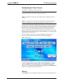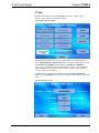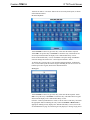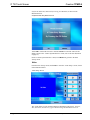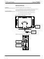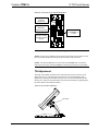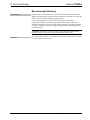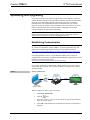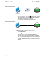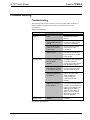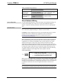
1
Crestron TPMC-9 9” Tilt Touch Screen Operations Guide Regulatory Compliance As of the date of manufacture, the TPMC-9 has been tested and found to comply with specifications for CE marking. Federal Communications Commission (FCC) Compliance Statement This device complies with part 15 of the FCC Rules. Operation is subject to the following conditions: (1) This device may not cause harmful interference and (2) this device must accept any interference received, including interference that may cause undesired operation. CAUTION: Changes or modifications not expressly approved by the manufacturer responsible for compliance could void the user’s authority to operate the equipment. NOTE: This equipment has been tested and found to comply with the limits for a Class B digital device, pursuant to part 15 of the FCC Rules. These limits are designed to provide reasonable protection against harmful interference in a residential installation. This equipment generates, uses and can radiate radio frequency energy and, if not installed and used in accordance with the instructions, may cause harmful interference to radio communications. However, there is no guarantee that interference will not occur in a particular installation. If this equipment does cause harmful interference to radio or television reception, which can be determined by turning the equipment off and on, the user is encouraged to try to correct the interference by one or more of the following measures: • Reorient or relocate the receiving antenna • Increase the separation between the equipment and receiver • Connect the equipment into an outlet on a circuit different from that to which the receiver is connected • Consult the dealer or an experienced radio/TV technician for help Industry Canada (IC) Compliance Statement CAN ICES-3(B)/NMB-3(B) The specific patents that cover Crestron products are listed at patents.crestron.com. Crestron, the Crestron logo, Capture HD, CresCAT, Cresnet, Crestron Home, Crestron Studio, Crestron Toolbox, DigitalMedia, Smart Graphics, SmartObjects, TouchPoint and VT Pro-e are either trademarks or registered trademarks of Crestron Electronics, Inc. in the United States and/or other countries. Microsoft and Windows are either trademarks or registered trademarks of Microsoft Corporation in the United States and/or other countries. Other trademarks, registered trademarks and trade names may be used in this document to refer to either the entities claiming the marks and names or their products. Crestron disclaims any proprietary interest in the marks and names of others. Crestron is not responsible for errors in typography or photography. This document was written by the Technical Publications department at Crestron. ©2014 Crestron Electronics, Inc. Crestron TPMC-9 9” Tilt Touch Screen Contents 9” Tilt Touch Screen: TPMC-9 1 Introduction ............................................................................................................................... 1 Features and Functions ................................................................................................ 1 Applications................................................................................................................. 4 Specifications .............................................................................................................. 5 Physical Description .................................................................................................... 7 Setup ........................................................................................................................................ 10 Network Wiring ......................................................................................................... 10 Identity Code ............................................................................................................. 10 Configuring the Touch Screen ................................................................................... 11 Hardware Hookup ..................................................................................................... 22 Tilt Adjustment.......................................................................................................... 23 Recommended Cleaning ............................................................................................ 24 Uploading and Upgrading ........................................................................................................ 25 Establishing Communication ..................................................................................... 25 Programs, Projects, and Firmware ............................................................................. 27 Program Checks ........................................................................................................ 27 Problem Solving ...................................................................................................................... 28 Troubleshooting......................................................................................................... 28 Check Network Wiring.............................................................................................. 29 Reference Documents ................................................................................................ 30 Further Inquiries ........................................................................................................ 30 Future Updates .......................................................................................................... 30 Return and Warranty Policies .................................................................................................. 31 Merchandise Returns / Repair Service ...................................................................... 31 Crestron Limited Warranty........................................................................................ 31 Operations Guide – DOC. 6965G Contents • i Crestron TPMC-9 9” Tilt Touch Screen 9” Tilt Touch Screen: TPMC-9 Introduction The TPMC-9 Tilt Touch Screen from Crestron® delivers high end style and performance in a striking tabletop design. Sleek and compact, the TPMC-9 features a generous 9” (~229 mm) widescreen display with advanced touch screen graphics, IP intercom, audio feedback and H.264 video. Features and Functions • • • • • • • • • • • • • • • * Operations Guide – DOC. 6965G Sleek, contoured design for tabletop use Elegant smooth black or white or textured black finishes Generous 9” (~229 mm) widescreen color touch screen 800 x 480 WVGA display resolution Smart Graphics™ support H.264 streaming video Wired composite video input Crestron IP intercom Customizable audio feedback Built-in microphone and speakers Crestron Home® CAT5 video connectivity High speed Ethernet and Cresnet® communications Built-in USB port for direct program upload Up to 45 degree tilt adjustment* Low profile single wire connection The tilt angle must be set to a fixed position for normal use. Adjustment of the tilt angle requires a 5/32” hex wrench (included). 9” Tilt Touch Screen: TPMC-9 • 1 Crestron TPMC-9 9” Tilt Touch Screen Advanced Touch Screen Control A Crestron touch screen offers an ideal user interface for controlling all the technology in a home, boardroom, classroom, courtroom or command center. Touch screens do away with piles of remote controls, cluttered wall switches and cryptic computer screens, simplifying and enhancing the technology. For controlling audio, video, lighting, shades, HVAC, security and other systems, Crestron touch screens are fully customizable with easy to use controls and icons, true feedback and real time status display, full-motion video windows and advanced navigation of digital media servers, tuners and other devices. Smart Graphics Crestron touch screens use Smart Graphics to deliver the ultimate user experience and the ultimate value, by enabling the creation of dynamically rich user interfaces with incredible efficiency and unparalleled functionality. Using Smart Graphics, programmers can swiftly integrate fluid gesture-driven controls, animated feedback, metadata, embedded apps and full-motion video for a deeply engaging and ultra-intuitive touch screen experience. Crestron Smart Graphics include the following enhancements: • Cool looking graphical buttons, sliders, knobs and gauges are intuitive and fun to use. • Kinetic effects enhance the feeling of realism with lists and toolbars that scroll with momentum at the flick of a fingertip. • Drag and drop objects snap into place offering an easy way to switch sources. • Dashboard widgets personalize the touch screen with clocks, weather, news and other information. • Customizable themes allow a completely different look and feel for every user, event or season. • Fully developed SmartObjects™ enable sophisticated control over complex devices with minimal programming. Integrated Video Streaming video capability makes it possible to view security cameras and other video sources right on the touch screen. Native support for H.264 and MJPEG formats allows the TPMC-9 to display live streaming video from an IP camera, a streaming server (Crestron CEN-NVS200* or similar), a DigitalMedia™ switcher, or a Capture HD® system. Streaming video is delivered to the touch screen over Ethernet, eliminating the need for any extra video wiring. A wired video input is also provided to allow viewing of a composite video source. Video images can be displayed full frame or in fully scalable windows anywhere on the touch screen. IP Intercom Equipped with integrated speakers and microphone, the TPMC-9 allows touch screen to touch screen voice communication and room monitoring via IP over Ethernet, eliminating the need for any special audio wiring, switchers or programming. * 2 • 9” Tilt Touch Screen: TPMC-9 Item(s) sold separately. Operations Guide – DOC. 6965G Crestron TPMC-9 9” Tilt Touch Screen Audio Feedback Customized audio files can be loaded on the TPMC-9 to add another dimension to the touch screen graphics using personalized sounds, button feedback and voice prompts. High Speed Connectivity Both Cresnet and Ethernet are standard on the TPMC-9, providing for easy network integration and seamless communications with Crestron control systems and other network devices. Versatile Install Options With its integral tilting base, the TPMC-9 provides a very clean and stylish touch screen solution for small countertops, desks, podiums and bedside tables. The screen tilt is installer adjustable at up to a 45 degree angle for optimal viewing and operation.1 A single cable exits the rear of the base. The 10 foot (3 meter) cable extends to a separate interface module (TPS-6X-IMCW2), which may be discreetly mounted on a flat surface or in a flush wall box, providing full connectivity for power, communications and video signals. Control system communication is afforded through Cresnet and Ethernet ports. Wired video connectivity is handled through a choice of balanced or unbalanced composite inputs, allowing compatibility with both conventional coaxial and Crestron Home Balanced AV distribution systems. 1. The tilt angle must be set to a fixed position for normal use. Adjustment of the tilt angle requires a 5/32” hex wrench (included). 2. Item included, refer to product specifications for additional information. Operations Guide – DOC. 6965G 9” Tilt Touch Screen: TPMC-9 • 3 Crestron TPMC-9 9” Tilt Touch Screen Applications The following diagram shows a TPMC-9 in a typical application. TPMC-9 in a Typical Application 4 • 9” Tilt Touch Screen: TPMC-9 Operations Guide – DOC. 6965G Crestron TPMC-9 9” Tilt Touch Screen Specifications Specifications for the TPMC-9 are listed in the following table. TPMC-9 Specifications SPECIFICATION DETAILS Touch Screen Display Display Type TFT active matrix color LCD Size 9 inch (229 mm) diagonal Aspect Ratio 15:9 WVGA Resolution 800 x 480 pixels Brightness 350 nits Contrast 700:1 Color Depth 24-bit, 16.7 M colors Illumination Edgelit fluorescent Viewing Angle ± 88º horizontal, ± 88º vertical Touch Screen Resistive membrane Memory DDR SDRAM 256 MB Flash 2 GB Maximum Project Size 60 MB Graphics Engine Supports Smart Graphics or “traditional” GUI projects Communications Ethernet 10/100, auto-switching, auto-negotiating, auto-discovery, full/half duplex, DHCP, for control and console Cresnet Cresnet slave mode for control and console USB USB client for console Video Analog Input Signal Types Composite Analog Formats NTSC 480i or PAL 576i Analog Color Depth 24-bit, 16.7 M colors Streaming Formats H.264 (MPEG-4 part 10 AVC) (320 x 240 / 15 fps @ 192 kbps recommended), MJPEG (320 x 240 / 10 fps recommended) Audio Features Built-in microphone and speakers, Crestron IP Intercom Audio Feedback Formats MP3 using Smart Graphics, WAV using “traditional” graphics Power Requirements Power Pack 2.0 amps @ 24 Vdc; 100 – 240 Vac, 50/60 Hz power pack included Cresnet Power Usage 18 watts (0.75 amps @ 24 Vdc) including 1, 2 TPS-6X-IMCW interface module 3 Default IP ID 03 (Continued on following page) Operations Guide – DOC. 6965G 9” Tilt Touch Screen: TPMC-9 • 5 Crestron TPMC-9 9” Tilt Touch Screen TPMC-9 Specifications (Continued) SPECIFICATION DETAILS Environmental Temperature 32º to 95º F (0º to 35º C) Humidity 10% to 90% RH (non-condensing) Heat Dissipation 61 Btu/h 4 Enclosure Plastic, 0° to 45° adjustable tilt mechanism , low profile base, integral 10 foot (3 meter) cable assembly Dimensions Height 7.09 in (180 mm) maximum 6.91 in (176 mm) minimum Width 10.72 in (273 mm) Depth 7.02 in (179 mm), 6.48 in (165 mm) without grommet Weight 4.1 lb (1.9 kg) Available Models TPMC-9-B 9” Tilt Touch Screen, Black Smooth TPMC-9-B-T 9” Tilt Touch Screen, Black Textured TPMC-9-W-S 9” Tilt Touch Screen, White Smooth Included Accessories Power Pack 24 Volt Power Pack, Universal TPS-6X-IMCW Interface Module Available Accessories CEN-NVS200 ® Network Video Streamer CRESCAT Crestron Home CAT5 AV Cable CRESNET Cresnet Control Cable VMK-WIN Touchpoint Virtual Mouse & Keyboard ® Software for Windows ® 1. Item included; refer to product specifications for additional information. 2. May be powered by power pack or Cresnet network power but not both. All power connections are made via the included TPS-6X-IMCW interface module. 3. Refer to “Identity Code” which starts on page 10 for details. 4. The tilt angle must be set to a fixed position for normal use. Adjustment of the tilt angle requires a 5/32” hex wrench (included). 6 • 9” Tilt Touch Screen: TPMC-9 Operations Guide – DOC. 6965G Crestron TPMC-9 9” Tilt Touch Screen Physical Description This section provides information on the connections, controls and indicators available on the TPMC-9. TPMC-9 Physical View Operations Guide – DOC. 6965G 9” Tilt Touch Screen: TPMC-9 • 7 Crestron TPMC-9 9” Tilt Touch Screen TPMC-9 Overall Dimensions (Front View) 10.72 in (273 mm) 7.80 in (198 mm) 6.91 in (176 mm) 4.70 in (120 mm) 6.98 in (178 mm) TPMC-9 Overall Dimensions (Side View) 45° 7.09 in (180 mm) 7.02 in (179 mm) 8 • 9” Tilt Touch Screen: TPMC-9 Operations Guide – DOC. 6965G Crestron TPMC-9 9” Tilt Touch Screen TPMC-9 Overall Dimensions (Rear View) 1 2 3 Connectors, Controls, and Indicators Operations Guide – DOC. 6965G # CONNECTORS, CONTROLS, AND INDICATORS DESCRIPTION 1 Reset Button (1) Miniature push button for hardware reset, on rear 2 USB 3 To Module (1) Mini-B USB console port, on rear; Mini-B to A USB cable included Integral 10 foot (3 meter) cable with 10-pin RJ-50 male connector; Connects to included TPS-6X-IMCW interface module; Refer to TPS-6X-IMCW interface module specifications for other connectors and additional information 9” Tilt Touch Screen: TPMC-9 • 9 Crestron TPMC-9 9” Tilt Touch Screen Setup Network Wiring When wiring the Cresnet network, consider the following: • Use Crestron Certified Wire. • Use Crestron power supplies for Crestron equipment. • Provide sufficient power to the system. CAUTION: Insufficient power can lead to unpredictable results or damage to the equipment. Use the Crestron Power Calculator to help calculate how much power is needed for the system (www.crestron.com/calculators). For Cresnet networks with 20 or more devices, use a Cresnet Hub/Repeater (CNXHUB) to maintain signal quality. For more details, refer to “Check Network Wiring” which starts on page 29. The TPMC-9 can also use high-speed Ethernet for communications between the device and a control system, computer, media server and other IP-based devices. For general information on connecting Ethernet devices in a Crestron system, refer to the Crestron e-Control Reference Guide (Doc. 6052) at www.crestron.com/manuals. Identity Code NOTE: The latest software can be downloaded at www.crestron.com/software. Net ID The Net ID of the TPMC-9 has been factory set to 03. The Net IDs of multiple TPMC-9 devices in the same system must be unique. The Net ID is set using the internal setup menu (refer to “Cresnet” on page 18). Net ID may also be set from a personal computer (PC) via Crestron Toolbox™ (refer to “Establishing Communication” which starts on page 25). When setting the Net ID, consider the following: • The Net ID of each unit must match an ID code specified in the Crestron Studio™ or SIMPL Windows program. • Each network device must have a unique Net ID. For more details, refer to the Crestron Toolbox help file. IP ID The IP ID is set within the TPMC-9’s IP table using the internal setup menu (refer to “IP Table” which starts on page 14). IP ID may also be set from a PC via Crestron Toolbox. For information on setting an IP table, refer to the Crestron Toolbox help file. The IP IDs of multiple TPMC-9 devices in the same system must be unique. When setting the IP ID, consider the following: 10 • 9” Tilt Touch Screen: TPMC-9 • The IP ID of each unit must match an IP ID specified in the Crestron Studio or SIMPL Windows program. • Each device using IP to communicate with a control system must have a unique IP ID. Operations Guide – DOC. 6965G Crestron TPMC-9 9” Tilt Touch Screen Configuring the Touch Screen The TPMC-9 is configured from the setup menu. NOTE: The only connection required to configure the touch screen is power. Refer to “Hardware Hookup” which starts on page 22 for details. NOTE: The TPMC-9 can take up to 45 seconds to boot to a display after initial power up. NOTE: If no project has been loaded or if an invalid project has been loaded, the touch screen displays an error message and defaults to the setup menu screen. The setup screens allow basic configuration procedures prior to regular operation of the touch screen. To enter the setup screens, touch the panel while applying power to the unit. The setup screens can also be entered by touching the upper left corner, lower left corner, upper right corner and lower right corner of the panel twice in sequence (upper left, lower left, upper right, lower right, upper left, lower left, upper right, lower right). This sequence must be performed within five seconds and touches must be all the way in the corners. The main “Setup” menu opens, as shown in the illustration that follows. The functions provided by each button are detailed in subsequent paragraphs. TPMC-9 “Setup” Menu The “Setup” menu provides access to all basic functions and parameters. There are buttons for Ethernet, IP Table, Video, Audio, Cresnet, Diagnostics and About. There are also buttons to increase and decrease Screen Brightness and Standby Timeout as well as a button to enable/disable system messages and a Save & Reboot button to save settings and reboot the touch screen. Ethernet Touch Ethernet to enter the “Ethernet Setup Menu”, shown in the illustration below. Operations Guide – DOC. 6965G 9” Tilt Touch Screen: TPMC-9 • 11 Crestron TPMC-9 9” Tilt Touch Screen “Ethernet Setup Menu” The “Ethernet Setup Menu” displays information about the Link Status, Control Connection, DHCP, MAC address, IP address, subnet, default gateway, primary DNS and secondary DNS. It also has an IP Address Settings button used to access the submenus for setting up IP address and DNS servers. Touch IP Address Settings to enter the “IP Address” screen, shown in the illustration below. Touch Return to go back to the main “Setup” menu. “IP Address” Screen DHCP is enabled by default. To enter a Static IP Address, Static Subnet Mask or Static Default gateway, first touch the DHCP Enabled button. The button text changes to Disabled. Then touch the appropriate button for the address to be entered (or changed). A numeric keypad opens, as shown in the illustration that follows. 12 • 9” Tilt Touch Screen: TPMC-9 Operations Guide – DOC. 6965G Crestron TPMC-9 9” Tilt Touch Screen Numeric Keypad Touch CLEAR to remove any previous entry. Then enter the address required. Touch OK to accept the entry or CANCEL to cancel the entry. This hides the numeric keypad and returns the display to the “IP Address” screen. On the “IP Address” screen, touch Save to keep the change or Cancel to cancel the change and return to the “Ethernet Setup Menu”. To enter (or change) the Static Primary DNS, Static Secondary DNS, Static Primary WINS or Static Secondary WINS, touch Edit DNS Servers >> on the “IP Address” screen. The “IP Address” screen changes to show these addresses, as shown in the illustration below. “IP Address” Screen (Showing DNS and WINS Servers) Touch the appropriate button for the address to be entered (or changed). The numeric keypad opens. Touch CLEAR to remove any previous entry. Then enter the address required. Touch OK to accept the entry or CANCEL to cancel the entry. This hides the numeric keypad and returns the display to the “IP Address” screen. On the “IP Address” screen, touch Save to keep the change or Cancel to cancel the change and return to the “Ethernet Setup Menu”. Touch << Edit IP Address to return to the previous “IP Address” screen. Operations Guide – DOC. 6965G 9” Tilt Touch Screen: TPMC-9 • 13 Crestron TPMC-9 9” Tilt Touch Screen IP Table From the main “Setup” menu, touch IP Table to enter the “Control System Interface” menu, shown in the illustration below. “Control System Interface” Menu The “Control System Interface” menu contains buttons for eight IP Table slots as well as Add IP, Edit IP and Remove IP buttons to facilitate editing entries. Touch the Auto Discovery Enabled button to toggle to Auto Discover Disabled. A Control Connection indicator lights in green to show a control system connection. Touch Cresnet to enter a Cresnet ID and to enable or disable Cresnet. (Refer to “Cresnet” on page 18 for details.) To add an IP entry to a blank slot, first touch one of the Empty IP Table Slot buttons, then touch Add IP. The “Edit IP Table Entry” screen is displayed, as shown below. “Edit IP Table Entry” Screen 14 • 9” Tilt Touch Screen: TPMC-9 Operations Guide – DOC. 6965G Crestron TPMC-9 9” Tilt Touch Screen Touch the IP Address / Hostname button. The on-screen keyboard opens, as shown in the illustration below. On-Screen Keyboard Touch CLEAR to remove any previous entry. Then enter the address required. Touch OK to accept the entry or CANCEL to cancel the entry. This hides the onscreen keyboard and returns the display to the “Edit IP Table Entry” screen. On the “Edit IP Table Entry” screen, touch Save to keep the change or Cancel to cancel the change and return to the “Control System Interface” menu. To edit the port, CIP ID or Device ID, touch the appropriate button. Touching the Port (41794) button opens the numeric keypad. Touching the CIP ID or Device ID buttons opens a hex keypad, shown in the illustration below. Hex Keypad Touch CLEAR to remove any previous entry. Then enter the ID required. Touch OK to accept the entry or CANCEL to cancel the entry. This hides the hex keypad and returns the display to the “Edit IP Table Entry” screen. From the “Control System Interface” menu, to edit or remove an IP entry, first touch the appropriate button containing the entry. Then touch Edit IP or Remove IP as appropriate. Editing an entry displays the “Edit IP Table Entry” screen (refer to the second illustration on page 14). Removing an entry displays a message saying Please Operations Guide – DOC. 6965G 9” Tilt Touch Screen: TPMC-9 • 15 Crestron TPMC-9 9” Tilt Touch Screen Confirm IP Table Entry Removal By Pressing the OK Button, as shown in the illustration below. Confirm IP Table Entry Removal Screen Touch OK to confirm the removal or touch CANCEL to cancel the removal. The display returns to the “Control System Interface” menu (refer to the first illustration on page 14). On the “Control System Interface” menu, touch Return to go back to the main “Setup” menu. Video From the main “Setup” menu, touch Video to enter the “Video Setup” screen, shown in the illustration below. “Video Setup” Screen The “Video Setup” screen contains buttons for adjustment of Brightness, Contrast, Hue, Saturation, Translucency, type of Deinterlacing and amount of Overscan. 16 • 9” Tilt Touch Screen: TPMC-9 Operations Guide – DOC. 6965G Crestron TPMC-9 9” Tilt Touch Screen There is also a Restore Defaults button to return to factory settings and a window to display video. Touch the video window for a full screen video display, as shown in the illustration below. Full Screen Video Display Touch Hide Controls to remove the controls. The button text changes to Show Controls. Touch Return to go back to the “Video Setup” screen. From the “Video Setup” screen, touch Return to go back to the main “Setup” menu. Audio From the main “Setup” menu, touch Audio to enter the “Audio Setup” screen, shown in the illustration below. “Audio Setup” Screen Operations Guide – DOC. 6965G 9” Tilt Touch Screen: TPMC-9 • 17 Crestron TPMC-9 9” Tilt Touch Screen The “Audio Setup” screen contains buttons for adjustment or muting of Master Volume, Wave Volume, KeyClick Volume and Intercom Volume. There is also a Play Test Wave button. Touch Return to go back to the main “Setup” menu. Cresnet From the main “Setup” menu, touch Cresnet to enter the “Cresnet Interface” screen, shown in the illustration below. “Cresnet Interface” Screen The “Cresnet Interface” screen contains buttons for setting the Cresnet ID and for enabling or disabling Cresnet. A Control Connection indicator lights in green to show a control system connection. Touch Return to go back to the main “Setup” menu. 18 • 9” Tilt Touch Screen: TPMC-9 Operations Guide – DOC. 6965G Crestron TPMC-9 9” Tilt Touch Screen Diagnostics From the main “Setup” menu, touch Diagnostics to enter the “Diagnostics” menu, shown in the illustration below. “Diagnostics” Menu The “Diagnostics” menu contains buttons for Test Patterns, Touch Test, Swipe Test, Mic Test and Calibrate Touch. This screen also displays Total RAM, Free RAM, as well as the current MAC and IP addresses. A Link Status indicator lights in green to show Ethernet activity and a Control Connection indicator lights in green to show a control system connection. Touch Test Patterns to display a selection of test pattern options, as shown in the illustration below. “Test Patterns” Menu Test pattern options include Display Color Bars, Display Vertical Lines, Display Gray Scale, Display Test Pattern, Display Grid Pattern, Display RGB Gradient and Display White. From any of these, touch the screen to return to the “Test Operations Guide – DOC. 6965G 9” Tilt Touch Screen: TPMC-9 • 19 Crestron TPMC-9 9” Tilt Touch Screen Patterns” menu. From the “Test Patterns” menu, touch Return to go back to the “Diagnostics” menu. From the “Diagnostics” menu, touch Touch Test to access touch screen calibration controls, as shown in the illustration below. Touch Test Screen Touch Calibrate to initiate touch screen calibration. During touch screen calibration, a crosshair appears at the center of the screen. Touch the center of the crosshair, which then moves to the upper left part of the screen. Touch the center of the crosshair and it moves to another part of the screen. Continue touching the center of the crosshair at each new location until calibration is complete. After calibration, the display returns to the screen shown above. Touch Return to go back to the “Diagnostics” menu. From the “Diagnostics” menu, touch Swipe Test to display the “Swipe Test” screen, as shown in the illustration below. “Swipe Test” Screen 20 • 9” Tilt Touch Screen: TPMC-9 Operations Guide – DOC. 6965G Crestron TPMC-9 9” Tilt Touch Screen Swiping a finger on screen, left to right, right to left, top to bottom or bottom to top lights the appropriate indicator, showing the swipe was recognized. Touch Return to go back to the “Diagnostics” menu. From the “Diagnostics” menu, touch Mic Test to display the “Diagnostics - Mic Test” screen, as shown in the illustration below. “Diagnostics – Mic Test” Screen This screen performs a test of the TPMC-9’s built-in microphone. The touch screen records audio for five seconds and then plays back the recorded sound. Speak into the microphone on the front of the TPMC-9 and the recording is played back to confirm the microphone is functioning. When playback is finished, the display goes back to the “Diagnostics” menu. The Calibrate Touch button on the “Diagnostics” menu initiates touch screen calibration, as does the Calibrate button on the Touch Test screen (refer to the “Touch Test Screen” illustration on page 20). From the “Diagnostics” menu, touch Return to go back to the main “Setup” menu. About From the main “Setup” menu, touch About to display the firmware version and operating system image version currently loaded on the TPMC-9. Touch Return to go back to the main “Setup” menu. Save & Reboot From the main “Setup” menu, touch Save & Reboot to save all settings, exit the setup screens and return to the main project. Operations Guide – DOC. 6965G 9” Tilt Touch Screen: TPMC-9 • 21 Crestron TPMC-9 9” Tilt Touch Screen Hardware Hookup Ventilation The TPMC-9 should be used in a well-ventilated area. To prevent overheating, do not operate this product in an area that exceeds the environmental temperature range listed in the table of specifications. Connect the Device When making connections to the TPMC-9, consider the following: 1. Use the included Crestron power supply for these devices. 2. The power supply cable cannot be extended. Hardware Connections for the TPMC-9 USB: To Computer To TO PANEL Connector on TPS-6X-IMCW Hardware Connections for the TPS-6X-IMCW (Front) TO PANEL: Connect to TPMC-9 POWER: From DC Power Pack 22 • 9” Tilt Touch Screen: TPMC-9 Operations Guide – DOC. 6965G Crestron TPMC-9 9” Tilt Touch Screen Hardware Connections for the TPS-6X-IMCW (Rear) POWER: From DC Power Pack VIDEO IN: Balanced or Unbalanced Source LAN: 10/100BASE-T to LAN NET: To Control System and Other Cresnet Devices NOTE: Ensure the TPS-6X-IMCW is properly grounded. NOTE: To prevent overheating, do not operate this product in an area that exceeds the environmental temperature range listed in the table of specifications. NOTE: The TPS-6X-IMCW can be powered via the 24 VDC jack on either the front or the back of the unit if the NET port is not being used to power the module. Tilt Adjustment The head of the TPMC-9 pedestal can be tilted 45 degrees from vertical. The tilt angle must be set to a fixed position for normal use. The tilt mechanism can be adjusted by loosening the tilt clutch using the 5/32” hex wrench included with the touch screen. Adjust to desired tilt angle, then lock the mechanism by tightening the tilt clutch. Refer to the illustration below. Touch Screen Tilt Clutch Adjustment Tilt Clutch Operations Guide – DOC. 6965G 9” Tilt Touch Screen: TPMC-9 • 23 Crestron TPMC-9 9” Tilt Touch Screen Recommended Cleaning Touch Screen Keep the surface of the touch screen free of dirt, dust or other materials that could degrade optical properties. Long-term contact with abrasive materials can scratch the surface, which may detrimentally affect image quality. For best cleaning results, use a clean, damp, non-abrasive cloth with any commercially available non-ammonia glass cleaner. Bezels may not provide a complete watertight seal. Therefore, apply cleaning solution to the cloth rather than the surface of the touch screen. Wipe touch screen clean and avoid getting moisture beneath the bezels. CAUTION: Do not apply excessive pressure to the touch screen display during handling. Doing so can crack the screen and damage the touch screen. Enclosure The soft felt bag the TPMC-9 came shipped in can be used to clean the bezel and the rest of the touch screen enclosure. 24 • 9” Tilt Touch Screen: TPMC-9 Operations Guide – DOC. 6965G Crestron TPMC-9 9” Tilt Touch Screen Uploading and Upgrading Crestron recommends using the latest programming software and that each device contains the latest firmware to take advantage of the most recently released features. However, before attempting to upload or upgrade it is necessary to establish communication. Once communication has been established, files (for example, programs, projects or firmware) can be transferred to the control system (or device). Finally, program checks can be performed (such as changing the device ID or creating an IP table) to ensure proper functioning. NOTE: Crestron software and any files on the website are for authorized Crestron dealers and Crestron Service Providers (CSPs) only. New users must register to obtain access to certain areas of the site (including the FTP site). Establishing Communication NOTE: For PCs running Windows 2000 or XP, ActiveSync 4.5 or later is required for Toolbox to communicate with the TPMC-9 via USB to upload firmware and display lists. Download and install ActiveSync from the Microsoft website (www.microsoft.com/windowsmobile/en-us/help/synchronize/device-synch.mspx). PCs running Windows Vista or 7 require Windows Mobile Device Center for communication with Toolbox. Download and install Windows Mobile Device Center (WMDC) from the Microsoft website (www.microsoft.com/windowsmobile/devicecenter.mspx). Use Crestron Toolbox for communicating with the TPMC-9; refer to the Crestron Toolbox help file for details. There are three methods of communication: indirect, TCP/IP and USB. Indirect Indirect Communication Serial, Control System TPMC-9 Cresnet N LA or USB AC CO R ET H TE RN M PU PW RSW W- -R AC QU IR ITY TIV E PC Running Crestron Toolbox TPMC-9 connects to control system via Cresnet: Operations Guide – DOC. 6965G 1. Click Tools | System Info. 2. Click the 3. For Connection Type, select Cresnet ID. In the Through drop-down menu, select the control system. 4. Click OK. Communications are confirmed when the device information is displayed. icon. 9” Tilt Touch Screen: TPMC-9 • 25 Crestron TPMC-9 9” Tilt Touch Screen TCP/IP Ethernet Communication TPMC-9 N LA PC Running Crestron Toolbox The TPMC-9 connects to PC via Ethernet: USB 1. Use the Device Discovery Tool (click the icon) in Crestron Toolbox to detect all Ethernet devices on the network and their IP configuration. The tool is available in Toolbox version 1.15.143 or later. 1. Click on the TPMC-9 to display information about the device. USB Communication TPMC-9 USB PC Running Crestron Toolbox The USB port on the TPMC-9 connects to the USB port on the PC: 26 • 9” Tilt Touch Screen: TPMC-9 1. Click Tools | System Info. 2. Click the 3. For Connection Type, select USB. When multiple USB devices are connected, identify the TPMC-9 by entering “TPMC-9” in the Model text box, the unit’s serial number in the Serial text box or the unit’s hostname (if known) in the Hostname text box. 4. Click OK. Communications are confirmed when the device information is displayed. icon. Operations Guide – DOC. 6965G Crestron TPMC-9 9” Tilt Touch Screen Programs, Projects, and Firmware Program, project or firmware files may be distributed from programmers to installers or from Crestron to dealers. Firmware upgrades are available from the Crestron website as new features are developed after product releases. One has the option to upload programs and projects via the programming software or to upload and upgrade via the Crestron Toolbox. For details on uploading and upgrading, refer to the Crestron Studio help file, SIMPL Windows help file, VT Pro-e® help file or the Crestron Toolbox help file. Crestron Studio or SIMPL Windows If a Crestron Studio (or SIMPL Windows) program is provided, it can be uploaded to the control system using Crestron Studio (or SIMPL Windows) or Crestron Toolbox. Crestron Studio or VT Pro-e Upload the Crestron Studio (or VT Pro-e) file to the touch screen using Crestron Studio (or VT Pro-e) or Crestron Toolbox. Firmware Check the Crestron website to find the latest firmware. (New users must register to obtain access to certain areas of the site, including the FTP site.) Upgrade TPMC-9 firmware via Crestron Toolbox. 1. Establish communication with the TPMC-9 and display the “System Info” window. 2. Select Functions | Firmware… to upgrade the TPMC-9 firmware. Program Checks Actions that can be performed on the TPMC-9 vary depending on whether it is connected via Cresnet or Ethernet. Cresnet Connections For Cresnet connections, using Crestron Toolbox, display the network device tree (Tools | Network Device Tree View) to show all network devices connected to the control system. Right-click on the TPMC-9 to display actions that can be performed on the TPMC-9. Ethernet Connections For Ethernet connections, display the “System Info” window (Tools | System Info) and select the Functions menu to display actions that can be performed on the TPMC-9. Be sure to use the internal setup menu (refer to “IP Table” which starts on page 14) or Crestron Toolbox to create the TPMC-9 IP table. In Toolbox: 1. Select Functions | IP Table Setup. 2. Add, modify or delete entries in the IP table. 3. A defined IP table can be saved to a file or sent to the device. Edit the control system’s IP table to include an entry for the TPMC-9. The entry should list the TPMC-9’s IP ID (specified on the TPMC-9’s IP table) and the internal gateway IP address 127.0.0.1. Operations Guide – DOC. 6965G 9” Tilt Touch Screen: TPMC-9 • 27 Crestron TPMC-9 9” Tilt Touch Screen Problem Solving Troubleshooting The following table provides corrective action for possible trouble situations. If further assistance is required, please contact a Crestron customer service representative. TPMC-9 Troubleshooting TROUBLE Device does not function. Touch screen is not responding. Touch screen display is dark. POSSIBLE CAUSE(S) CORRECTIVE ACTION TPMC-9 is not receiving power. Verify power to (included) TPS-6X-IMCW Interface Module. Device is not communicating with the network. Use Crestron Toolbox to poll the network. Verify network connection to the device. Device is not receiving power from a Crestron power source. Use the provided Crestron power source. Verify connections. Device is not receiving sufficient power. Use the Crestron Power Calculator to help calculate how much power is needed for the system. Touch screen Net ID is not set to match the Net ID in the SIMPL program. Use Crestron Toolbox to poll the network. Verify the Net ID for the touch screen is properly set to match the Net ID in the SIMPL program. Touch screen Net ID is not unique; two or more units share the same ID. Use Crestron Toolbox to poll the network and verity that each ID is used only once. No IP address configured/obtained on the TPMC-9. Use the internal setup menu (refer to “IP Table” which starts on page 14) or Crestron Toolbox to create/verify Ethernet settings. Invalid control system IP address / IP ID set up on the TPMC-9. The IP address (or host name) for the control system is invalid or the IP ID does not match the one defined in the SIMPL program. Refer to “Ethernet” which starts on page 11 and to “IP Table” which starts on page 14 to define IP addresses. Standby timeout has elapsed. Touch the screen to reactivate. (Continued on following page) 28 • 9” Tilt Touch Screen: TPMC-9 Operations Guide – DOC. 6965G Crestron TPMC-9 9” Tilt Touch Screen TPMC-9 Troubleshooting (Continued) TROUBLE POSSIBLE CAUSE(S) CORRECTIVE ACTION Unexpected response from touch screen. Touch screen is incorrectly calibrated. Recalibrate the touch screen (refer to “Diagnostics” which starts on page 19). TPMC-9 boots up in setup screens every time. Invalid VT Pro-e project or no VT Pro-e project is loaded. Load/reload VT Pro-e project using the Toolbox. Check Network Wiring Use the Right Wire To ensure optimum performance over the full range of the installation topology, use Crestron Certified Wire only. Failure to do so may incur additional charges if support is required to identify performance deficiencies because of using improper wire. Calculate Power CAUTION: Use only Crestron power supplies for Crestron equipment. Failure to do so could cause equipment damage or void the Crestron warranty. CAUTION: Provide sufficient power to the system. Insufficient power can lead to unpredictable results or damage to the equipment. Use the Crestron Power Calculator to help calculate how much power is needed for the system (www.crestron.com/calculators). When calculating the length of wire for a particular Cresnet run, the wire gauge and the Cresnet power usage of each network unit to be connected must be taken into consideration. Use Crestron Certified Wire only. If Cresnet units are to be daisy chained on the run, the Cresnet power usage of each network unit to be daisy chained must be added together to determine the Cresnet power usage of the entire chain. If the unit is home-run from a Crestron system power supply network port, the Cresnet power usage of that unit is the Cresnet power usage of the entire run. The wire gauge and the Cresnet power usage of the run should be used in the following equation to calculate the cable length value on the equation’s left side. Cable Length Equation L< 40,000 RxP Where: L = Length of run (or chain) in feet R = 6 Ohms (Crestron Certified Wire: 18 AWG (0.75 mm2 )) or 1.6 Ohms (Cresnet HP: 12 AWG (4 mm 2 )) P = Cresnet power usage of entire run (or chain) Make sure the cable length value is less than the value calculated on the right side of the equation. For example, a Cresnet run using 18 AWG Crestron Certified Wire and drawing 20 watts should not have a length of run more than 333 feet (101 meters). If Cresnet HP is used for the same run, its length could extend to 1250 feet (381 meters). N OTE: All Crestron certified Cresnet wiring must consist of two twisted pairs. One twisted pair is the 24 and G pair and the other twisted pair is the Y and Z pair. Operations Guide – DOC. 6965G 9” Tilt Touch Screen: TPMC-9 • 29 Crestron TPMC-9 9” Tilt Touch Screen Strip and Tin Wire When daisy chaining Cresnet units, strip the ends of the wires carefully to avoid nicking the conductors. Twist together the ends of the wires that share a pin on the network connector and tin the twisted connection. Apply solder only to the ends of the twisted wires. Avoid tinning too far up the wires or the end becomes brittle. Insert the tinned connection into the Cresnet connector and tighten the retaining screw. Repeat the procedure for the other three conductors. Add Hubs Use of a Cresnet Hub/Repeater (CNXHUB) is advised whenever the number of Cresnet devices on a network exceeds 20 or when the combined total length of Cresnet cable exceeds 3000 feet (914 meters). Reference Documents All documents mentioned in the guide are available at www.crestron.com/manuals. List of Related Reference Documents DOCUMENT TITLE Crestron e-Control Reference Guide Further Inquiries To locate specific information or resolve questions after reviewing this guide, contact Crestron's True Blue Support at 1-888-CRESTRON [1-888-273-7876] or, for assistance within a particular geographic region, refer to the listing of Crestron worldwide offices at www.crestron.com/offices. To post a question about Crestron products, log onto Crestron’s Online Help at www.crestron.com/onlinehelp. First-time users must establish a user account to fully benefit from all available features. Future Updates As Crestron improves functions, adds new features and extends the capabilities of the TPMC-9, additional information may be made available as manual updates. These updates are solely electronic and serve as intermediary supplements prior to the release of a complete technical documentation revision. Check the Crestron website periodically for manual update availability and its relevance. Updates are identified as an “Addendum” in the Download column. 30 • 9” Tilt Touch Screen: TPMC-9 Operations Guide – DOC. 6965G Crestron TPMC-9 9” Tilt Touch Screen Return and Warranty Policies Merchandise Returns / Repair Service 1. No merchandise may be returned for credit, exchange or service without prior authorization from Crestron. To obtain warranty service for Crestron products, contact an authorized Crestron dealer. Only authorized Crestron dealers may contact the factory and request an RMA (Return Merchandise Authorization) number. Enclose a note specifying the nature of the problem, name and phone number of contact person, RMA number and return address. 2. Products may be returned for credit, exchange or service with a Crestron Return Merchandise Authorization (RMA) number. Authorized returns must be shipped freight prepaid to Crestron, 6 Volvo Drive, Rockleigh, N.J. or its authorized subsidiaries, with RMA number clearly marked on the outside of all cartons. Shipments arriving freight collect or without an RMA number shall be subject to refusal. Crestron reserves the right in its sole and absolute discretion to charge a 15% restocking fee plus shipping costs on any products returned with an RMA. 3. Return freight charges following repair of items under warranty shall be paid by Crestron, shipping by standard ground carrier. In the event repairs are found to be non-warranty, return freight costs shall be paid by the purchaser. Crestron Limited Warranty Crestron Electronics, Inc. warrants its products to be free from manufacturing defects in materials and workmanship under normal use for a period of three (3) years from the date of purchase from Crestron, with the following exceptions: disk drives and any other moving or rotating mechanical parts, pan/tilt heads and power supplies are covered for a period of one (1) year; touch screen display and overlay components are covered for 90 days; batteries and incandescent lamps are not covered. This warranty extends to products purchased directly from Crestron or an authorized Crestron dealer. Purchasers should inquire of the dealer regarding the nature and extent of the dealer's warranty, if any. Crestron shall not be liable to honor the terms of this warranty if the product has been used in any application other than that for which it was intended or if it has been subjected to misuse, accidental damage, modification or improper installation procedures. Furthermore, this warranty does not cover any product that has had the serial number altered, defaced or removed. This warranty shall be the sole and exclusive remedy to the original purchaser. In no event shall Crestron be liable for incidental or consequential damages of any kind (property or economic damages inclusive) arising from the sale or use of this equipment. Crestron is not liable for any claim made by a third party or made by the purchaser for a third party. Crestron shall, at its option, repair or replace any product found defective, without charge for parts or labor. Repaired or replaced equipment and parts supplied under this warranty shall be covered only by the unexpired portion of the warranty. Except as expressly set forth in this warranty, Crestron makes no other warranties, expressed or implied, nor authorizes any other party to offer any warranty, including any implied warranties of merchantability or fitness for a particular purpose. Any implied warranties that may be imposed by law are limited to the terms of this limited warranty. This warranty statement supersedes all previous warranties. Crestron software, including without limitation, product development software and product operating system software is licensed to Crestron dealers and Crestron Service Providers (CSPs) under a limited non-exclusive, non-transferable license pursuant to a separate end-user license agreement. The terms of this end user license agreement can be found at www.crestron.com/legal/software_license_agreement. Operations Guide – DOC. 6965G 9” Tilt Touch Screen: TPMC-9 • 31 Crestron Electronics, Inc. 15 Volvo Drive Rockleigh, NJ 07647 Tel: 888.CRESTRON Fax: 201.767.7576 www.crestron.com Operations Guide – DOC. 6965G (2027214) 02.14 Specifications subject to change without notice.