1
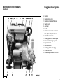
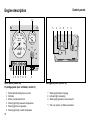
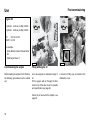
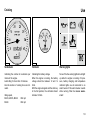
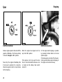
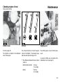
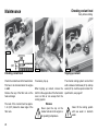
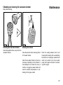
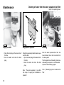
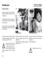
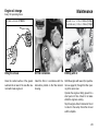
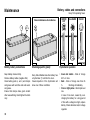
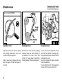
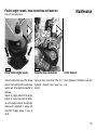
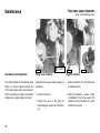
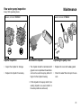
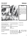
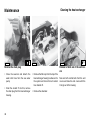
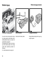
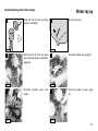
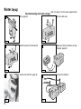
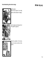
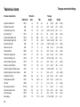
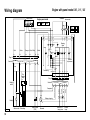
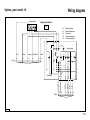
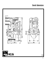
M2.C5 M2.D5 M2.06 M3.09 Operation manual M2.06 VD01027 M2.C5 M2.D5 M2.06 M3.09 Operation manual Serial numbers Engine serial number Vetus: Mitsubishi: Gearbox serial number: 340102.04 Please enter the serial numbers here. These numbers should be quoted when inquiring about Customer Service, Repairs or Spare Parts (see page 6). We reserve the right to make any changes without previous notice. Please read and observe the information given in this operation manual. This will enable you to avoid accidents, preserve the manufacturer’s warranty and maintain the engine in peak operating condition. pliance with the conditions laid down by the manufacturer for operation, maintenance and servicing. The engine should only be operated, maintained and serviced by persons which are familiar with the former and the hazards involved. For the Guarantee Conditions, see the Vetus Diesel Service and Warrantee Manual. The relevant accident prevention guidelines and other generally accepted safety and industrial hygiene regulations must be observed. This engine has been built exclusively for the application specified in the scope of supply and is to be used only for the intended purpose. Any use exceeding that scope is considered to be contrary to the intended purpose. The manufacturer will not not assume responsibility for any damage resulting therefrom. The risks involved are to be borne by the user. Use in accordance with the intended purpose also implies com- Unauthorized engine modifications will invalidate any liability claims against the manufacturer for resultant damage. Manipulations of the injection and regulating system may also influence the performance of the engine, and its emissions. Adherence to legislation on pollution cannot be guaranteed under such conditions. Contents Serial numbers 1 Introduction 1 4 5 Maintenance 6 Winter lay-up Checking the oil level 23 Winter storage procedure Checking the coolant level 24 Recommissioning after winter Checking and cleaning the 2 Engine description raw water strainer General 6 Draining water from the water Identification of engine parts 8 separator/fuel filter 26 (Bleeding) 26 Changing the oil 28 Control panels 10 storage 51 7 Troubleshooting 54 8 Technical Data 60 25 Battery, cables and cable 3 Use 49 9 Operating media 11 connections Lubrication Oil 65 First commissioning 12 Checking the gearbox oil level 32 Fuel 66 Running-in 15 Changing the gearbox oil 33 Coolant 67 Starting 16 Checking valve clearance 34 Pre-heating 17 Replacing the fuel filter 36 68 19 38 10 Wiring Diagrams Cruising Checking the V-belt Stopping 20 Checking flexible engine mounts39 11 Overall Dimensions 70 General guidelines 4 Routine maintenance Introduction 21 Maintenance schedule 22 30 Checking hose connections 39 Checking fastenings 39 Checking the raw water pump 40 Coolant replacement 42 Cleaning the heat exchanger 44 Checking engine rpm 47 Introduction Dear customer, Vetus diesel engines are designed both for pleasure and commercial craft. Consequently, a wide range of variants are offered to meet the requirements of specific cases. Your engine is appropriately equipped for your vessel, which means that not necessarily all components described in this manual are mounted to your engine. We have endeavoured to highlight any differences so that you will able to locate the operating and maintenance instructions relevant to your engine quickly and easily. Please read this manual before starting your engine and always observe the operating and maintenance instructions. We are available to help with any additional inquiries. Sincerely, Vetus den Ouden n.v. Introduction Safety measures All safety instructions in this manual are designated by the accompanying symbol. Please follow them carefully. • Never attempt to touch moving parts when the engine is running. • Never touch hot parts of the engine, and keep flammable materials well away from the engine. Pass the safety instructions to other persons operating the engine as well. General regulations and laws for safety and accident prevention must also be observed. • Always stop the engine before checking or adjusting components. • Always stop the engine before checking or topping up the coolant or oil. • Never open cap on top of header tank when the engine is at operating temperature. • Always carry out maintenance safely by only using tools well matched in size. Engine description VD01044 General VD01036 VD01035 Engine data tag Engine data tag location Engine serial number The Vetus engine serial number and performance data are printed on the engine data tag. The Vetus engine data tag is attached to the flywheel housing. The Mitsubishi engine serial number is stamped on the fuel injection pump. (arrow) Model and engine serial number must be given when ordering spare parts. Engine description General Maximum rpm adjustment screw Lead seal VD00152 VD00153 VD00150 Adjustments to the fuel pump are to be carried out by authorized Vetus-Mitsubishi Service specialists only. Cylinder numbering Fuel pump seal Cylinders are numbered consecutively, beginning at the front end. The manufacturer shall not be held liable for damages resulting from adjustments made to the fuel injection pump. The maximum engine speed adjustment screw has been sealed to prevent this. Engine description 1 2 3 4 5 6 7 8 9 10 11 12 13 14 15 16 17 18 Identification of engine parts Service side Oil filler cap Raw water inlet ø 20 mm Raw water pump Oil dipstick Manual operation of fuel supply pump Oil filter Water separator/fuel filter drain plug Water separator/Fuel filter Connection for gearbox push-pull cable Fuse Electrical system connector box Fuel return pipe connection ø 8 mm Air inlet silencer Water separator/fuel filter air bleed nipple Manual operation of electric stop Fuel supply pipe connection ø 8 mm Fuel lift pump Connection for throttle push-pull cable VD01028 M2.06 Engine description Identification of engine parts Starter side VD01029 19 20 21 22 23 24 25 26 27 28 29 30 31 32 33 Gearbox Gearbox drain plug Gearbox oil dipstick/filler cap Starter motor Alternator V-belt Connection for extra expansion tank (Keel cooling model only) Calorifier connection Cooling system air bleed nipple Filler cap for cooling system Expansion tank Heat exchanger Cooling system drain plug Airvent connection Exhaust injection bend ø 40 mm M2.06 Engine description 1 Control panels 2 4 5 6 7 8 9 5 4 6 8 7 3 3 VD00103 VD00102 Basic panel (model 22) Fly-bridge panel (excl. voltmeter, model 21) Sailingboat panel (model 10) 7 Warning light battery charging 8 Indicator light pre-heating 9 Warning light gearbox low oil pressure * 1 2 3 4 5 6 10 Tachometer/Operating hours counter Voltmeter Starter pre-heat switch/lock Warning light high raw water temperature Warning light low oil pressure Warning light high coolant temperature *) This is an option, not fitted as standard. Use General guidelines General guidelines for use Implementing the following recommendations will result in longer life and better performance and more economical operation of your engine. • Carry out the maintenance described regularly, including the ‘Daily procedures before starting’. • Use anti-freeze in the engine coolant all year long, this helps prevent corrosion as well as protecting against frost damage. For specifications see page 67. • Never run the engine without a thermostat. • Use a good quality lubricating oil. For specifications see page 65. • Use a good quality diesel fuel that is free of water and other pollutants. • Always stop the engine immediately if one of the warning lamps for oil pressure, high coolant temperature, high raw water temperature or battery charging lights up. 11 Use Engine Oil First commissioning OIL OIL 2 Cylinder: 2.4 litres (4 UKpt) 15W40 3 Cylinder: 3.6 litres (6 UKpt) 15W40 API: CD, CE or CF4 CCMC: D4, D5 For example: - Vetus Marine Inboard Diesel Motor Oil - Shell Super Diesel T VD01013 Commissioning the engine Filling with engine oil Before starting the engine for the first time, the following procedures must be carried out: As a rule engines are delivered empty of oil. Fill the engine with oil through the filler neck on top of the valve cover, for quantity and specification see page 65. Check the oil level with the dipstick, see page 23. 12 VD01002 A second oil filling cap is located at the distribution cover. Use First commissioning Vetus engines are normally equipped with ZF-Hurth or Technodrive gearboxes. OIL OIL In case your engine is equipped with another brand of gearbox follow the instructions given in the supplied owners manual. VD01024 17 VD01024 27 Filling gearbox with oil Fill the gearbox with oil. Check the oil level with the dipstick, see page 32. ZF Hurth: type HBW50 : type HBW100 : type HSW150V : 0,3 litres (1/2 UKpt) 0,35 litres (2/3 UKpt) 1,0 litre (1 3/4 UKpt) ATF: Automatic Trans mission Fluid type A, Suffix A. Technodrive: type TMC40 :0,20 litres (1/3 UKpt), Engine oil SAE 20/30 13 Use First commissioning Coolant quantities : 2 Cil.: 2.2 litres (4 UKpt) 3 Cil.: 3.0 litres (5 UKpt) Water If a water heater is connected to the engine and this heater is positioned above the upper side of the engine then bleeding of the heater will not take place automatically! Fill the heater separately to bleed the cooling system completely. (3/8”) VD01004 VD00158 heater VD01005 Filling the cooling system Remove the cap of the filler neck on the top of the heat exchanger housing. Remove the bolt from the upper side of the thermostat cover, so that air can escape from the cooling system. Fill the cooling system. Use a mixture of 40% antifreeze (ethyleneglycol based) and 60% tap water or use a special coolant. For specifications see page 67. 14 The level of the coolant must be approx. 1 cm (3/8”) below the lower edge of the filler neck. Bleeding will take place automatically during filling! Replace the filler cap. After the engine has run for the first time and has reached operating temperature and has cooled down again to ambient temperature, check the coolant level in the heat exchanger housing. If necessary, add coolant. Never fill the cooling system with sea water or brackish water. First commissioning Running-in FUEL Use Never fill the fuel tank while the engine is running. Do not spill fuel. Prevent unnecessary pollution. VD00002 Fuel Other preparations Running-in Ensure that the fuel tank is filled with diesel fuel. Use only clean, water-free, commercial approved diesel fuel. For fuel grade see page 66. Bleed the fuel system, see page 26. • Check battery and cable connections. In order to ensure a long life for your engine, please observe the following for the first 50 operating hours: • Start the engine, see page 16, and let it run for about 10 minutes without load. Check the engine and all connections (fuel, cooling water and exhaust) for leaks. • Allow the engine to reach operating temperature before applying a load. • Avoid fast acceleration. • Do not allow the engine to run faster than 3/4 of maximum RPM. 15 Use Before starting, ing points: • • • • • Starting always check the follow- Engine oil level. Coolant level. Sea cock open. Main switch ‘on’. Gearbox in ‘neutral’ position. neutral gearbox reverse gearbox forward forward throttle reverse throttle VD00111 VD00112 After repair work: Preparation starting Check that all guards have been replaced and that all tools have been removed from the engine. When starting with pre-heating, do not use any other substance (e.g. injection with ‘Easy Start’). Doing so could result in an accident. Before starting the engine, always check that the control lever(s) is (are) in the neutral position. Never start the engine with the fuel injection pump removed. Disconnect battery. 16 half throttle, gearbox not engaged Set the control lever to ‘half throttle’ without engaging the gearbox. Use Starting Ambient Temperature Pre-heating time Above + 5°C (41°F) about 6 seconds VD00107 about 12 seconds Below -5°C (23°F) about 18 seconds Maximum pre-heating time 1 minute VD00108 Pre-heating Turn the start key on the instrument panel clock-wise; the warning lights for oil pressure and alternator will now light up and the alarm buzzer will sound. +5°C to -5°C (+41°F to +23°F) Turn the key further clockwise to the ‘ position; only the pre-heating indicator light will be lit now. Pre-heating time ’ The ideal pre-heating time depends on ambient temperature; the lower the ambient temperature, the longer the pre-heating time required. See table. Hold the key in this position for about 6 seconds. Warning To prevent the glow plugs from burning out, never exceed the stated maximum pre-heating time. 17 Use Starting VD00109 Warning Warning Release the key if the engine does not fire within 10 seconds. Wait until the starter motor has stopped running completely before turning the key to the ‘start’ position again. Never allow the starter motor to run for more than 30 seconds consecutively. Never turn the key to the ‘start’ position while the engine is running. Doing so will damage the starter motor. Check that the indicator lights for oil pressure and alternator are off. Cooling water should now flow out of the exhaust; if this is not the case, stop the engine immediately. Before submitting the engine to full load it should be brought up to operating temperature as quickly as possible by running at 3/4 of maximum revs. never turn the main switch off while the engine is running. The instrument panel is provided with the following instruments (Depending of the type of panel, see page 10). VD00110 Starting Now turn the key further to the ‘start’ position. Release the key as soon as the engine fires (the key will return to the ‘on’ position) and throttle back. Leave the key in this position while the engine is running. 18 Use Cruising VD00114 VD00113 Tachometer Voltmeter Warning lights Indicating the number of revolutions per minute of the engine. Avoid idling for more than 10 minutes. Also the number of running hours is indicated. Indicating the battery voltage. When the engine is running, the battery voltage should be between 12 and 14 Volts. With the engine stopped and the start key in the first position, the voltmeter should indicate 12 Volts. None of the five warning lights should light up while the engine is running. Oil pressure, battery charging and temperature indicator lights are all connected to an alarm buzzer. If this alarm buzzer sounds while running, Stop the engine immediately! Idling speed, M2.C5, M2.D5, M2.05 M3.09 :850 rpm :850 rpm 19 Use VD00105 Stopping VD00106 Electrical shutdown Reduce engine speed to idle and shift the gearbox to ‘Neutral’. Turn the key entirely to the left, through the ‘Off’ position. Never stop the engine immediately after it has been in operation for a long time. Allow the engine to idle for a few minutes before stopping. 20 VD01037 Mechanical shutdown When the engine has stopped, turn the key to the ‘Off’ position. If the engine is not to be used for some time, it is recommended that the sea cock is closed and the battery main switch turned off. On the engine itself stopping is possible by pressing the black button on the fuel injection pump. If the fuel supply is not shut off by the electrically operated fuel solenoid stopping of the engine can be done this way. Routine Maintenance Introduction Introduction The following guidelines should be observed for daily and periodic maintenance. Perform each function at the indicated time interval. The intervals stated are for normal operational conditions. Service the unit more frequently under severe conditions. Failure to carry out maintenance can result in faults and permanent damage to the engine. No claim can be made on the Guarantee if maintenance has been neglected. 21 Routine Maintenance Maintenance schedule Every 10 hours or daily, before starting Every 500 hours, at least once every year Check engine oil level 23 Gearbox oil change 33 Check coolant level 24 Check valve clearance 34 Check water strainer 25 Replace fuel filter 36 Check V-belt 38 Check flexible engine mounts 39 After the first 50 hours Drain water from fuel filter 26 Check engine for leaks 39 Engine oil change 28 Check tightness of all fasteners, bolts and nuts 39 Replace oil filter 28 Gearbox oil change 33 Every 1000 hours, at least once every 2 years Replace fuel filter 36 Raw water pump inspection 40 Check idle rpm 47 Replace coolant 42 Every 100 hours, at least once every year When required Drain water from fuel filter 26 Bleeding fuel system 26 Engine oil change 28 Cleaning heat exchanger 44 Replace oil filter 28 Check idle rpm 47 Battery, cables and cable connections 30 Check gearbox oil level 32 Stop the engine before carrying out any maintenance work. 22 Maintenance Checking engine oil level Daily, before starting. VD01001 VD00155 VD01013 Check oil level Oil level Topping up oil Turn the engine off. The dipstick is located on the starboard side of the engine. The oil level must be at or near the upper mark on the dipstick*. If necessary top up with the same brand and type of oil. The oil filling cap is on top of the the valve cover,. *) The difference between the two oil level marks is: M2.C5, M2.D5, M2.06 : 1,0 litres (1 3/4 UKpt) M3.09 : 1,8 litres (3 1/4 UKpt) A second oil filling cap is located at the distrubution cover, see page 12. 23 Maintenance Checking coolant level Daily, before starting. VD01003 (3/8”) VD00158 VD01005 VD01004 Checking coolant level Check the coolant level in the header tank. This has to be checked when the engine is cold. Remove the cap of the filler neck on the heat exchanger. The level of the coolant must be approx. 1 cm (3/8”) below the lower edge of the filler neck. 24 Topping up coolant If necessary, top up. When topping up coolant, remove the bolt from the upper side of the thermostat cover, so that air can escape from the cooling system. Warning Never open the cap on the header tank when the engine is at operating temperature. The internal cooling system can be filled with a mixture of anti-freeze (40 %) and tap water (60 %) or with a special coolant. For specification, see page 67 Never fill the cooling system with sea water or brackish water. Checking and cleaning the raw water strainer Daily, before starting. VD00125 Checking the raw water strainer Check daily whether there is any dirt in the raw water strainer. Maintenance CT30119 Cleaning the strainer Close the seacock before removing the lid of the water strainer. Clean the raw water strainer as often as is necessary, depending on the pollution of the waterways, but at least once every 6 months. A clogged raw water strainer will result in excessive temperatures or overheating of the engine coolant. Check the sealing between the lid and housing after cleaning and re-assembling the strainer. An improperly sealed lid will result in air sucked in by the sea water pump which again will result in overheating of the engine. 25 Maintenance VD01006 Draining of water from the water separator/fuel filter Every 100 operating hours. CT30119 VD01007 13 Empty fuel filter Empty water separator Bleeding • Open the drain plug at the lower side of the filter. • Drain the water and close the drain plug. Empty the separately installed water separator/fuel filter: • Open the drain plug at the lower side of the filter. • Drain the water and close the drain plug. After the water separator/fuel filter has been drained, the air has to be bled from the fuel system The fuel system is self-bleeding; but manual bleeding the system is recommended. Open the two bleeding nipples. Note : The water separator is not within the scope of supply but installation is required! One (1) bleeding nipple is located at the filter. 26 Maintenance Draining of water from the water separator/fuel filter Every 100 operating hours. VD01008 10 14 VD01009 VD00109 Start the engine A second bleeding nipple is located at the fuel injection pump. Prime the fuel system by pumping the fuel pump. Close the bleeding nipples when all air has escaped. N.B. It is necessary to operate the lever over the full stroke for proper operation. Operate the starter switch until the engine fires; release the starter switch if the engine does not fire within 20 seconds. Wait until the starter motor has stopped before making a new attempt to start the engine. Repeat the above if the engine cuts out after a short time. 27 Maintenance Engine oil change Every 100 operating hours. Engine oil change Change the engine oil every 100 hours of operation (together with engine oil filter replacement). If the engine runs less than 100 hours during the year the oil should be changed at least once a year. Run the engine for a few minutes before changing the oil; warm oil can be pumped out more easily. VD01010 Change the oil with a switched off engine at operation temperature. (Lube oil temperature approx. 80°C (176°F).) Be aware of the risk of skin burning during draining the hot oil! Used oil must be collected in a container for proper disposal according to laws and regulations. 28 VD01026 Draining the oil Removing the oil filter Remove the dipstick; insert the suction hose of the supplied sump pump in the dipstick tube. Push down the pump handle quickly and pull it up slowly. Unscrew the oil filter, with a commercially available tool, when all the oil has been pumped out. Catch any dripping oil. Beware of burns from hot oil. Maintenance Engine oil change Every 100 operating hours. Oil filter, art.code: Amount of oil: 2 Cil.: 2.9 litres (5 UKpt) (oil filter incl.) 3 Cil.: 4.1 litres (7 UKpt) STM0051 VD00124 VD01011 VD01013 Oiling the oil seal Oil filter installation Refilling with oil Clean the contact surface of the gasket. Lubricate the oil seal of the new filter element with clean engine oil. Install the filter in accordance with the instructions printed on the filter element housing. Refill the engine with new oil (for specification see page 65) through the filler opening in the valve cover. Operate the engine at idling speed for a short period of time. Check for oil leaks whilst the engine is running. Stop the engine. Allow 5 minutes for the oil to return to the sump. Check the oil level with the dipstick. 29 Maintenance Battery, cables and connections Every 100 operating hours. Vetus maintenance-free batteries VD00117 VD00118 Green Dot VD00121 All Dark VD00122 clear VD00123 Battery, battery connections Checking specific gravity Hydrometer operation Keep battery clean and dry. Remove battery cables (negative first). Clean battery posts (+ and -) and clamps and grease with acid-free and acid-resistant grease. Ensure that clamps make good contact after reassembling. Hand tighten the bolts only. Every Vetus Maintenance-free battery has a hydrometer (1) built into the cover. Visual inspection of the hydrometer will show one of three conditions: • Green dot visible - State of charge 65 % or more. • Dark - State of charge less than 65 %. Recharge immediately. • Clear or light yellow - Electrolyte level low. In case of low level, caused by overcharging the battery for a long period of time with a voltage too high, replace battery. Check alternator and/or voltage regulator. 30 Maintenance Battery, cables and connections Every 100 operating hours. Conventional batteries Conventional batteries Specific gravity State of charge 1.280 100% 1.200 50% 1.120 10% VD00119 recharge recharge immediately VD00120 Checking electrolyte level Checking specific gravity For conventional batteries it is required to check the electrolyte level regularly. Remove vent caps (taking care no spark or open flame is nearby) and inspect the level. Fluid should be 10 to 15 mm (3/8” to 5/8”) above top of all plates. If necessary top up with distilled water. Replace vent caps and charge the battery for 15 minutes at 15 - 25 Amps to mix electrolyte. Measure the electrolyte specific gravity of the individual cells with a commercial hydrometer. The hydrometer reading (see table) indicates the state of charge. Hydrometer reading of all cells should be at least 1.200 and show less than 0.050 between high and low. If not, recharge or replace battery. During checking the temperature of the electrolyte should preferably be 20°C (68°F). The gases emitted by the battery are explosive! Keep sparks and naked flames away from the battery! Do not allow battery acid to come into contact with skin or clothing! Wear protective goggles! Do not rest tools on the battery! 31 Maintenance VD01038 Gearbox oil level check Every 500 operating hours. 17 VD01032 Oil level check (ZF-Hurth) Oil level check (Technodrive) Unscrew the dipstick out of the gearbox housing. The oil level must between the two marks on the dipstick If necessary top up. The fillercap is on top of the gearbox housing. For oil type and specification see page 65. Check the oil level by cleaning the dipstick and lowering it into the hole, without screwing it in. The oil level should be between the end and the notch in the dipstick. If necessary top up by pouring oil in the dipstick hole. For oil type and specification see page 65. 32 Vetus engines are normally equipped with ZF-Hurth or Technodrive gearboxes. Consult the supplied Owners Manual for more details about care and maintenance. In case your engine is equipped with another brand of gearbox follow the instructions given in the supplied owners manual for changing oil and other care and maintenance. Maintenance Changing the gearbox oil Every 500 operating hours. VD01043 VD01042 VD01034 Draining the oil Drain the oil with the aid of a separate sump pump. Remove the dipstick (ZF-Hurth, 17) or remove the dipstick (Technodrive, 27). Insert the suction hose of the sump pump in the dipstick hole. Push down the pump handle quickly and pull it up slowly. Remove the sump pump when all the old oil has been pumped out. Filling with new oil Or, if sufficient space below the gearbox is available, oil can be drained by removing the drain plug. Drain plug: ZF-Hurth Technodrive 17 14 Collect the oil in a dripping pan. Refill the gearbox to the correct level via the dipstick opening (ZF-Hurth, 17) or via the filling hole (Technodrive, 27). For oil specification see page 65. In case your engine is equipped with another brand of gearbox follow the instructions given in the supplied owners manual for changing oil and other care and maintenance. 33 Maintenance Checking valve clearance Every 500 operating hours. Mark on gearcase 2 Cil.: 17° 3 Cil.: 19° VD01040 Checking / adjusting valve clearance Checking the valve clearance must be done with a cold engine, that is an engine which did not run for at least 6 hours. 10 Injection timing mark 27 Remove rocker cover Locating TDC Remove the 2 nuts of the rocker cover. Complete the following steps: Locate the Top Dead Center (TDC), at the end of the compression stroke, for cylinder 1 by barring the engine slowly until the TDC marks of the engine block and the crank pulley match. Note: There are two TDC’s e.g. compression and suction. At the TDC at the end of the compression stroke the rocker arm 34 VD00149 TDC mark does not move when the crank pulley is rotated a little. Maintenance Checking valve clearance Every 500 operating hours. Valve clearance:Inlet 0.25 mm (0.010”) Exhaust 0.25 mm (0.010”) VD01016 10 VD00152 VD00153 Adjusting valve clearance Cylinders are numbered consecutively, beginning at the front end. 2-cilinder engine • Check valve clearance at cylinder 1 and adjust if necessary. 3-cilinder engine • Check valve clearance at cylinder 1 and adjust if necessary. • Rotate the crankshaft 180° clockwise and check valve clearance at cylinder 2. • Rotate the crankshaft 240° clockwise and check valve clearance at cylinder 3. • Again rotate the crankshaft 240° and check valve clearance at cylinder 2. 35 Maintenance Fuel filter replacement Every 500 operating hours. Fuel filter, art.code: STM3690 VD00154 VD01017 Fuel filter removal Fuel filter installation The fuel filter is to be replaced as a unit. • Close the fuel stopcock. • Clean any debris from the filter carrier rim. • Remove the fuel filter, use a filter wrench. Catch any fuel. • Lubricate the rubber gasket sparingly with clean engine oil. VD00133 • Install the filter. When the rubber gasket touches the housing, apply another tightening of a half to three quarters of a turn by hand. • Open fuel stopcock. • Fill the new filter with clean diesel fuel. • Check for leaks. Keep naked flames away when working on the fuel system. Do not smoke! 36 Maintenance Fuel filter replacement Every 500 operating hours. VD00109 Bleeding Start the engine After replacing the fuel filter the air has to be bled from the fuel system. Operate the starter switch until the engine fires; release the starter switch if the engine does not fire within 20 seconds. Wait until the starter motor has stopped before making a new attempt to start the engine. For bleeding see page 26. Repeat the above if the engine cuts out after a short time. 37 Maintenance V-belt, art.code: Checking the V-belt Every 500 operating hours. STM7369 VD00034 VD00128 VD00129 12 14 Inspection V-belt Checking tension Tensioning V-belt Inspect the belt for wear and tear (fraying and cracking). Belts which are in poor condition should be replaced. Check tension of the V-belt by applying moderate finger and thumb pressure. If the deflection of the belt is more than 12 mm (1/2”), using about 10 kg (20 lbs) thumb pressure, it should be tensioned. Loosen the bolt of the adjustment bracket and both the alternator mounting bolts. Now push the alternator outwards until the belt tension is correct. Now first re-tighten the upper mounting bolt of the alternator. Then re-tighten the bolt of the adjustment bracket and the lower mounting bolt. Check, tension and change belts only with the engine off. Refit belt guard, if provided. 38 Flexible engine mounts, hose connections and fasteners Every 500 operating hours. VD01039 Maintenance VD01041 Check flexible engine mounts Inspection hose connections Check fasteners Check the bolts which secure the damper element, the mounting bolts to engine bed and the nuts at the adjustment spindle for tightness. Inspect the rubber element of the engine support for cracks. Also check the deflection of the damper element, the deflection influences the alignment of engine and propshaft! Re-align engine in case of doubt. Inspect all hose connections of the coolingsystem. (Cracked hoses, loose hose clamps) Check tightness of all fasteners, bolts and nuts. 39 Maintenance Raw water pump inspection Every 1000 operating hours. VD01022 1,6 x 6,3 VD01030 VD01031 Raw water pump inspection Pump cover removal Impeller removal The rubber impeller of the outboard water pump is not proof against running dry. If the water supply has been blocked, it may be necessary to replace the impeller. Always carry a spare impeller on board. Inspection where appropriate changing is as follows: • Slide the impeller off of the shaft using a waterpump plier. • Close the sea cock. • Mark the impeller to ensure correct re-installation if it is to be re-used. The impeller must be installed in the same position as removed. • Remove the cover of the pump by unscrewing the screws out of the housing. 40 Maintenance Raw water pump inspection Every 1000 operating hours. Impeller, art.code: STM8061 VD00127 Gasket, VD00004 art.code: STM8002 VD00156 Impeller inspection Re-install the impeller Replacing the pump cover • Inspect the impeller for damage. • The impeller should be lubricated with glycerin or a non-petroleum based lubricant such as a silicone spray before fitting it into the impeller housing. • Replace the cover with a new gasket. • Replace the impeller if necessary. • Check the water filter and open the sea cock. • Fit the impeller to the pump shaft. (if an existing impeller is re-used, install it in the same position as removed). 41 Maintenance Coolant replacement Every 1000 operating hours. Coolant replacement The coolant has to be replaced every 1000 operating hours or at least once every two years. 1 N.B. Replacing the coolant may also be necessary as part of the winter storage procedure; in case that the coolant present in the cooling system offers insufficient protection for the winter. 2 VD01025 14 Draining of coolant Be aware of the risk of skin burning during draining the hot coolant! Used coolant must be collected in a container for proper disposal according to laws and regulations. 42 Remove the drain plugs from the engine block (1) and heat exchanger (2). Remove the filler cap to vent the cooling system and check that all the coolant has been drained. After draining replace the drain plugs. VD01018 13 Maintenance Coolant replacement Every 1000 operating hours. Coolant: quantities : 2 Cil.: 2.2 litres (4 UKpt) 3 Cil.: 3.0 litres (5 UKpt) Water heater If a water heater is connected to the engine and this heater is positioned above the upper side of the engine than bleeding of the heater will not take place automatically! Fill the heater separately to bleed the cooling system completely. (3/8”) VD01004 VD00158 VD01005 Filling the cooling system Remove the cap of the filler neck on the top of the heat exchanger housing. Remove the bolt from the upper side of the thermostat cover, so that air can escape from the cooling system. Fill the cooling system. Use a mixture of 40% antifreeze (ethyleneglycol based) and 60% tap water or use a special coolant. For specifications see page 67. The level of the coolant must be approx. 1 cm (3/8”) below the lower edge of the filler neck. Bleeding will take place automatically during filling! Replace the filler cap. After the engine has run for the first time and has reached operating temperature and has cooled down again to ambient temperature, check the coolant level in the heat exchanger housing. If necessary, add coolant. Never fill the cooling system with sea water or brackish water. 43 Maintenance VD01018 Cleaning the heat exchanger 13 VD01003 Remove the drain plug • Close the seacock and detach the water inlet hose from the sea water pump. • Drain the coolant: To do this, remove the drain plug from the heat exchanger housing. 44 • Remove the filler cap from the top of the heat exchanger housing to allow air into the system and check that all coolant has drained off. • Remove the alternator. VD01019 6 Removal of bolts out of the end covers Take out both central bolts from the end covers and take the end covers with the O-rings out of the housing. Maintenance Cleaning the heat exchanger VD01020 6 VD01021 STM7217 Remove heat exchanger Cleaning the heat exchanger Slide the heat exchanger out of the housing. Clean the heat exchanger: Use a pipe cleaner to remove fouling in the pipes. Then rinse the heat exchanger pipes with clean water. Ensure that both heat exchanger end chambers are free from dirt. 45 Maintenance Cleaning the heat exchanger O-ring, VD00157 Replacing heat exchanger Replace the heat exchanger in the original position in the heat exchanger housing. Use new O-rings (61 x 2.5 mm) which have been greased. art.code: STM6113 (2 x) STM6202 Replacing the end covers Fit the end covers in the housing; the connector cover is fitted with a locating pin so that it can be fitted in one way only in relation to the heat exchanger. This ensures the correct position of the separator baffle in the connector cover in relation to the heat exchanger. Tighten up the bolts when both covers are in the correct position. • Refit the drain plug. • Reconnect removed. all hoses previously • Refill the cooling system, see page 43. 46 Maintenance Checking engine speed Warning Minimum speed adjustment screw The maximum engine speed adjustment screw has been correctly set at the factory and sealed. DO NOT attempt to remove this seal. Maximum speed adjustment screw Lead seal VD00134 At full load (with the boat cruising) the maximum engine speed should be about 3,000 resp. 3600 RPM (see technical data page 60). If the engine does not reach this speed, it is being overloaded! If this is the case, check the ship’s propeller for defects or irregularities, and also to see that it is the correct pitch and diameter. VD00150 10 Checking engine speed Adjusting engine idling speed The engine idling speed should be 850 rpm. Allow the engine to warm up normally (until the coolant temperature reaches at least 60°C (140°F).) before checking and/ or adjusting the idling speed. Check the engine RPM using a rev. counter, or use the rev. counter fitted to the control panel. If the engine speed differs from that stated above, it must be adjusted. The engine idling speed can be reset using the adjustment screw on the fuel pump. 47 Winter lay-up VD01006 Fuel system Drain the water from the water separator/ fuel filter and the fuel tank. Ensure that the tank is completely filled with fuel. Winter storage procedure VD00136 Running with protective fuel mixture Connect the fuel supply pipe to a can filled with a mixture of one (1) part of engine oil* to nine (9) parts of clean fuel**. Use this mixture to run the engine at no load for approx. 10 minutes. Stop the engine. * Engine oil with protective properties. E.g. Shell Super Diesel T 10W40 **Preferably water-free fuel. Collect some fuel from the return pipe, while engine is running. Never run the engine under load with this mixture of fuel and oil. 48 Winter lay-up Winter storage procedure VD01010 VD00125 Lubrication system Raw water cooling system With the engine still at operating temperature: (If not, run the engine until warm, then turn off.) Close the seacock before removing the lid of the water strainer. If necessary, clean the raw water strainer. Pour 1 litre (1/4 Imp.gal.) of anti-freeze into the water strainer and run the engine until the anti-freeze has disappeared into the cooling system. Take care that no anti-freeze is spilled into the waterway (anti-freeze is poisonous). Replace the oil filter and change the engine oil; use oil with protective properties. See page 65. Check the seal between the lid and housing after cleaning and re-assembling the strainer. An improperly sealed lid will result in air sucked in by the raw water pump which again will result in overheating of the engine. 49 Winter lay-up VD01003 Winter storage procedure VD00139 CT40063 Fresh water cooling system Electrical system Charging the batteries To avoid corrosion during winter storage the cooling system must be filled with an antifreeze/water mixture (or a coolant). For specifications see page 67. N.B. Replacing the coolant is only necessary if the coolant present in the cooling system offers insufficient protection for the winter. For coolant replacement see page 42. Disconnect the battery cables. Charge batteries during winter lay-up regularly if required! 50 Winter lay-up Recommissioning after winter storage 1 Check that the lid of the raw water strainer is reinstalled. VD00125 2 VD01045 Open the sea cock. VD00138 Check that the lid of the raw water pump and drain plugs are reinstalled. (pages 40) VD01022 3 4 5 Check the coolant level. (page 24) VD01003 Re-tighten clamps. possible loose hose 6 Check the engine oil level. (page 23) VD01001 51 Winter lay-up Recommissioning after winter storage 7 filter. (page 26) VD00027 8 VD01017 52 Open the fuel valve. VD00137 Drain the water from the fuel tank. VD00141 9 Drain the water from the water separator/fuel 11 Make sure that the batteries are fully charged. (page 30) CT40063 Install a new fuel filter. (page 36) 12 VD00140 Connect the batteries. Recommissioning after winter storage 13 Winter lay-up Start the engine. Check the fuel system, the cooling system and the exhaust for leakage. VD01046 14 Stop the engine and change the oil of the gearbox. (page 33) VD01043 15 Check the operation of the instruments, the remote control and the gearbox. VD00142 53 Troubleshooting General Engine faults are in most cases caused by improper operation or insufficient maintenance. In case of a fault, always check first that the operation and maintenance instructions have been followed. In the following tables information is given about the possible causes of faults and suggested remedies. Please note that these tables can never be complete. If you are unable to identify the cause of the fault or to rectify it yourself, then contact the nearest service representative. Before starting, make sure that nobody is in the immediate vincinity of the engine. When carrying out repair, never start the engine with the fuel injection pump removed removed. Disconnect battery! 54 Troubleshooting Fault finding table 1 Engine will not crank 2 Engine cranks but will not start, no smoke from exhaust Possible fault Remedy Possible fault Remedy a a a a b Faulty or discharged battery. Loose or corroded connections in starting circuit. c Faulty starter-switch or faulty starter-relay. d Faulty starter-motor or pinion does not engage. e Starter relay is not engaged due to a voltage too low; caused by a very long intermediate cable from engine to control panel. Check / recharge battery and check engine alternator and/or battery charger. b Clean and tighten connections. c Check / replace. b c d e f Check / replace startermotor. e Install an auxiliary starter relay. Fuel stop valve closed. (Nearly) Empty fuel tank. Air in fuel system. Fuel filter clogged with water and/or contamination. Leaking fuel supply line or fuel injection line. Faulty injector/injection pump. d g Vent line of fuel supply tank clogged. h Exhaust restricted. Open. Refill. c Check and bleed. d Check or replace. b e Check / replace. f Check, replace if required. g Check / clean. h Check. 55 Troubleshooting Fault finding table 3 Engine cranks but will not start, smoke from exhaust 4 Engine starts but runs unevenly (rough idling) or stalls Possible fault Remedy Possible fault Remedy a Air in fuel system. Faulty injector/injection pump. a a a b b c Setting of stop valve incorrect. Faulty glow plugs. e Incorrect valve clearance. f Incorrect injection timing after overhauling of engine. g Insufficient intake air. c d d f Check and bleed. Check, replace if required. Check / adjust. Check / replace. Adjust. Check / adjust. g Check. f h h b i 56 Wrong fuel quality or contaminated fuel. Incorrect lube oil SAE class or quality for ambient temperature. b e Check fuel. Drain and flush fuel tank. Replace with new fuel. i Replace. (Nearly) Empty fuel tank. Air in fuel system. c Fuel filter clogged with water and/or contamination. d Leaking fuel supply line or fuel injection line. e Faulty injector/injection pump. g h i j k Vent line of fuel supply tank clogged. Fuel supply line restricted. Incorrect valve clearance. Idle setting too low. Exhaust restricted. Wrong fuel quality or contaminated fuel. Refill. Check and bleed. c Check or replace. d Check / replace. e Check, replace if required. f Check / clean. g Check / clean. Adjust. i Check/ adjust. j Check. k Check fuel. Drain and flush fuel tank. Replace with new fuel. h Troubleshooting Fault finding table 5 Engine does not reach maximum rpm under load 6 Engine overheats Possible fault Remedy Possible fault Remedy a Air in fuel system. Fuel filter clogged with water and/or contamination. c Leaking fuel supply line or fuel injection line. d Faulty injector/injection pump. a Faulty injector/injection pump. a b Check and bleed. Check or replace. a b b c Check / replace. d e Setting of stop valve incorrect. Oil level too high. Incorrect valve clearance. Exhaust restricted. Insufficient intake air. Wrong fuel quality or contaminated fuel. e Engine overloaded. k Check, replace if required. Check / adjust. Lower level. Adjust. Check / clean. Check. Check fuel. Drain and flush fuel tank. Replace with new fuel. Check size of propeller. b Oil level too high. c Oil level too low. Faulty oil filter. d e Coolant pump defective. Heat exchanger dirty or clogged f as a result of rubber particles from a worn impeller. g Check / top up. Coolant level too low. Sea cock closed. h Open. i Check / clean. Raw water strainer clogged. j Check / replace. Leaking raw water intake system. k Check / replace. Faulty thermostat. Faulty impeller raw water pump. l Check / replace. m Check / replace air Insufficient intake air. intake filter. n Check / replace. Motor becomes apparantly overheated as a result of faulty temperature switch, sensor or meter. f g h i j k c d f g h i j e f g h i j k l m n Check, replace if required. Lower level. Increase level. Replace. Check / clean. Check / clean. 57 Troubleshooting Fault finding table 7 Engine not firing on all cylinders 8 Engine has little or no oil pressure Possible fault Remedy Possible fault Remedy a a a b Check and bleed. Check or replace. a b b b c Check / replace. Air in fuel system. Fuel filter clogged with water and/or contamination. c Leaking fuel supply line or fuel injection line. d Faulty injector/injection pump. e Fuel supply line restricted. Faulty glow plugs. g Incorrect valve clearance. f Check, replace if required. e Check / clean. f Check / replace. g Adjust. Oil level too low. Excessive inclination of engine. c Incorrect lube oil SAE class or quality for ambient temperature. d 9 Engine oil consumption excessive Possible fault Remedy a a b c d e f 58 Increase level. Check / Adjust. c Replace. Oil level too high. Excessive inclination of engine. Incorrect lube oil SAE class or quality for ambient temperature. Excessive wear of cylinder/ piston. Insufficient intake air. Engine overloaded. Lower level. Check / Adjust. c Replace. b d Check compression; overhaul engine. e Check. f Check size of propeller. Troubleshooting Fault finding table 10A Blue exhaust smoke (idling) 10C White exhaust smoke (at full load) Possible fault Remedy Possible fault Remedy a a a Air in fuel system. Faulty injector/injection pump. a c Water in fuel system. Faulty glow plugs. e Incorrect valve clearance. f Incorrect injection timing. g Wrong fuel quality or contaminated fuel. c d d h h b Oil level too high. Excessive inclination of engine. 10B b Lower level. Check / Adjust. Black exhaust smoke (at load) Possible fault Remedy a a b c Insufficient intake air. Faulty injector / injection pump. Engine overloaded, max. rpm is not reached. b Vapour in exhaust gases condenses as a result of very low ambient temperature. b e f g Check and bleed. Check, replace if required. Check water separator. Check / replace. Adjust. Check / adjust. Check fuel. Drain and flush fuel tank. Replace with new fuel. - Check. Check / replace if required. c Check sizes of propeller. b 59 Technical data Model Engine specifications M2.C5 M2.D5 M2.06 M3.09 General Make Number of cylinders Based on Type Injection Aspiration Bore Stroke Total displacement Compression ratio Idling speed Max. no. of revolutions at no load Valve Clearances (cold) Weight (with standard gearbox) 2 L2C-61DM 70 mm 70 mm 538 cm3 23 : 1 850 rpm 3000 rpm 98 kg (216 lbs) Vetus Mitsubishi 2 2 L2C-61DM L2E-61DM 4-stroke diesel, in-line Indirect Natural 70 mm 76 mm 70 mm 70 mm 538 cm3 635 cm3 23 : 1 23 : 1 850 rpm 850 rpm 3600 rpm 3600 rpm Inlet 0.25 mm (0.010”) Exhaust 0.25 mm (0.010”) 98 kg (216 lbs) 98 kg (216 lbs) 3 L3E-61DM 76 mm 70 mm 952 cm3 23 : 1 850 rpm 3600 rpm 123 kg (271 lbs) Engine installation Max. installation angle Max. athwartships angle 60 15 degrees backwards 25 degrees continuously, 30 degrees intermittent Technical data Engine specifications Model M2.C5 M2.D5 M2.06 M3.09 Maximum Output at the flywheel (ISO 3046-1) at the prop shaft (ISO 3046-1) at no. of revolutions of Torque, 8.2 kW (11 hp) 9.5 kW (13 hp) 11.8 kW (16 hp) 18.4 kW (25 hp) 7.9 kW (10.7 hp) 9.3 kW (12.6 hp) 11.6 kW (15.8 hp) 17.7 kW (24 hp) 3000 rpm 3600 rpm 3600 rpm 3600 rpm 26 Nm 25 Nm 29.3 Nm 49.1 Nm (2.7 kgm, 19.2 ft.lb) (2.6 kgm, 18.4 ft.lb) (3.0 kgm, 21.6 ft.lb) (5.0 kgm, 36.2 ft.lb) at no. of revolutions 3000 rpm 3600 rpm 3600 rpm 3600 rpm Fuel consumption 265 g/kW.h (195 g/hp.h, 6.9 oz/hp.h) 2300 rpm 265 g/kW.h (195 g/hp.h, 6.9 oz/hp.h) 2300 rpm 268 g/kW.h (196 g/hp.h, 6.9 oz/hp.h) 2500 rpm 256 g/kW.h (187 g/hp.h, 6.6 oz/hp.h) 2600 rpm at no. of revolutions Fuel System (Self-bleeding) Injection pump Injectors Opening pressure Firing order Injection timing Fuel filter element Fuel lift pump Suction height max. Fuel supply connection Fuel return connection 1 - 2 17° BTDC STM3690 Bosch model NC (Nippon Denso) Plug injector 140 bar (kgf/cm3) (2030 psi) 1 - 2 1 - 2 17° BTDC 17° BTDC STM3690 STM3690 1- 3 - 2 19° BTDC STM3690 max. 1,5 m (5 ft) for hose 8 mm (5/16”) I.D. for hose 8 mm (5/16”) I.D. 61 Technical data Model Engine specifications M2.C5 M2.D5 M2.06 M3.09 Oil lubrication system Oil capacity, max. without oil filter with oil filter Oil Filter Oil temperature in sump 2,4 litres (4 UKpt) 2,9 litres (5 UKpt) 2,4 litres (4 UKpt) 2,4 litres (4 UKpt) 2,9 litres (5 UKpt) 2,9 litres (5 UKpt) STM0051 max. 130°C (266°F) 3,6 litres (6 UKpt) 4,1 litres (7 UKpt) 2.2 litres (4 UKpt) 3 litres (5 UKpt) 2.2 litres (4 UKpt) 2,2 litres (4 UKpt) 3 litres (5 UKpt) 3 litres (5 UKpt) opening at 71°C±1.5°C (160°F±3°F), fully opened at 84°C (183°F) 3 litres (4 UKpt) 4 litres (5 UKpt) Cooling system Capacity, Intercooler version Keel cooler version Thermostat Coolant pump, Flow at max. engine rpm Total head keelcooler at max. flow Inlet connection for hose keelcooler Raw water pump, Flow at max. engine rpm Total head at max. flow Impeller Inlet connection for hose Heater supply connection Heater return connection 62 50 l/min (11 UKGal/min) 2 m Water (6’ 7”) 28 mm (1 1/8”) I.D. 20 l/min (4.4 UKGal/min) 2 m Water (6’ 7”) STM8061 20 mm (3/4”) I.D. 10 mm (3/8”) 8 mm (5/16”) Technical data Engine specifications Model M2.C5 M2.D5 M2.06 M3.09 40 mm 40 mm 40 mm at specified output max. 150 mbar (2.2 psi) 40 mm Exhaust system Exhaust diameter Exhaust back pressure Electrical System Voltage Alternator Battery capacity Protection 12 Volt 14 Volt, 40 Amp 12 Volt 12 Volt 12 Volt 14 Volt, 40 Amp 14 Volt, 40 Amp 14 Volt, 40 Amp min. 55 Ah, max. 108 Ah Tubular glass fuse, 32 x 6.3 mm 10 A slow blow V-belt STM7369 Gearbox STM7369 STM7369 STM7369 ZF Hurth: model HBW50 model HBW100 model HBW150V 2.05 / 2.72 : 1 — 2.05 / 2.72 : 1 Gear ratio 2.05 / 2.72 : 1 2.05 / 2.72 : 1 — — 2.05 / 2.72 : 1 2.05 / 2.72 : 1 2.05 : 1 2.72 : 1 2.05 / 2.72 : 1 Technodrive: model TMC40 2.00 / 2.60 : 1 2.00 / 2.60 : 1 2.00 / 2.60 : 1 2.00 / 2.60 : 1 63 Technical data Screw connection Cylinder head bolt Torque wrench settings Diameter Wrench size M10 14 Nm 78 Torque (kgm) (ft.lbf) ±5 (8 ±0.5) (58 ±3.5) Cilinder head bolt M8 12 25 ±5 (2.5 ±0.5) (18 ±3.5) Connecting rod nut M8 14 33 ±1.5 (3.35 ±0.15) (24 ±1) Fly wheel bolt M10 17 88 ±5 (9 ±0.5) (65 ±3.5) Crank shaft pulley nut M16 24 108 ±10 (11 ±1.0) (80 ±7) Main bearing cap bolt M10 17 52 ±2.5 (5.25 ±0.25) (38 ±2) Rocker stay bolt M8 12 18 ±3.5 (1.85 ±0.35) (13 ±2.5) Valve cover nut M6 10 6 ±1 (0.6 ±0.1) Nozzle holder M20 21 54 ±5 (5.5 ±0.5) (40 ±3.5) Fuel leak oil pipe nut M12 17 25 ±5 (2.5 ±0.5) (18 ±3.5) (4.5 ±0.8) Nozzle retaining nut M16 21 37 ±2.5 (3.75 ±0.25) (27 ±2) Fuel injection pipe nut M12 17 29 ±5 (3.0 ±0.5) (21 ±3.5) Delivery valve holder M16 17 36 ±2 (3.7 ±0.2) (26 Injection pump hollow screw M10 14 12 ±2.5 (1.25 ±0.25) (9 Injection pump air vent screw M6 10 6 ±1 (0.6 ±0.1) Solenoid lock nut M30 36 44 ±5 (4.5 ±0.5) (32 Temperature switch M16 19 22.5 ±4 (2.3 ±0.4) (16.5 ±3) Oil filter M20 — 12 (1.2 ±0.1) ±1 ±1.5) ±2) (4.5 ±0.8) (9 ±3.5) ±0.8) Oil pressure switch PT1/8 26 10 ±2 (1 ±0.2) (7 ±1.5) Pressure relief valve M18 22 44 ±5 (4.5 ±0.5) (32 ±3.5) Oil drain plug M18 19 54 ±5 (5.5 ±0.5) (40 ±3.5) Glow plug M10 12 17.5 ±2.5 (1.75 ±0.25) (13 ±2) 64 Operating media Lubricating oil Engine Lubricating Oil Gearbox Lubricating Oil Only use a recognised brand of oil for lubricating the engine. Only use a recognised brand of oil for lubricating the gearbox. Lube oils are differentiated according to their performance and quality class. In common use are specifications named after API (American Petroleum Institute) and CCMC (Committee of Common Market Automobile Constructors). Approved API Oils : CD, CE and CF4 Approved CCMC Oils : D4, D5 ZF Hurth:, type HBW50 :0,3 litres (1/2 UKpt) ATF*) type HBW100 :0,35 litres (2/3 UKpt) ATF*) type HBW150V :1,0 litres (1 3/4 UKpt) ATF*) As the viscosity of lube oil is dependent on temperature, the oil vicosity (SAE grade) should be selected according to the ambient temperature when the the engine is started. To avoid oil changes dictated by the seasons we advise one of the following multi-grade oils. - SAE 10W40 for temperatures of -25°C up to +30°C (-13°F up to +86°F) - SAE 15W40 for temperatures of -20°C up to +35°C (-4°F up to +95°F) For example: *) ATF :AutomaticTransmission Fluid; Transmissie olie type A, Suffix A. For example :Vetus Marine Gearbox Oil Shell Donax T6 Gulf Dextron Technodrive: type TMC40 :0,20 litres (1/2 UKpt), Engine oil SAE 20/30 Other brands of gearboxes: See supplied owners manual for oil type and quantities. Vetus Marine Inboard Motor Oil Shell Super Diesel T 65 Operating media Fuel Fuel Quality Grade Winter-grade fuel Use commercially available diesel fuel with less than 0.5% sulfer content. If the sulfur content is higher than 0.5%, the intervals between oil changes should be halved e.g. change oil every 250 hours. Don’t use fuel with more than 1% sulfur! Waxing may occur at low temperatures, clogging the fuel system and reducing engine efficiency. If the ambient temperature is less than 0°C (+32°F), winter-grade fuel -suitable down to -15°C (+5°F) - should be used. This fuel is usually available from filling stations well in advance of the cold months. Diesel fuel containing additives (Super Diesel) is often on sale as well, for use down to -20°C (-4°F). The following fuel specifications / standards are approved: • CEN EN 590 or DIN/EN 590 (under development) • DIN 51 601 (Feb. 1986) • BS 2869 (1988): A1 and A2 • ASTM D975-88: D1 and D2 • NATO Code F-54 and F75 The exhaust emission levels determined during certification by the supervising authority are always based on the reference fuel described by law. 66 Operating media Coolant Coolant fluid Water quality for coolant preparation The preparation and monitoring of coolant in inter-cooled engines is especially important because corrosion, cavitation and freezing can lead to engine damage. Use as coolant a mixture of a cooling system protective liquid (anti-freeze, ethylene glycol based) and tap water. Use preferably tap water. In tropical climates, where anti-freeze availability may be limited, use a corrosion inhibitor to protect the engine cooling system. The concentration of the cooling system protective liquid in the coolant should not fall below/exceed the following limits: Cooling system protective Water Protection against liquid (Anti-freeze) freezing to max. 45 vol% 55% -35°C (-31°F) 40 vol% 60% -28°C (-18°F) min. 35 vol% 65% -22°C (-8°F) The protective liquid concentration must be maintained under all circumstances. Therefor if coolant must be added always use the same mixture of anti-freeze and tap water. If an other available fresh water is used; the values given below must not be exceeded. Water quality min. pH-value at 20°C (68°F) 6.5 max. 8.5 Chloride ion content [mg/dm3] – 100 Sulfate ion content [mg/dm3] – 100 Total hardness [degrees] 3 12 Never use sea-water or brackish water. Cooling system protective liquids must be disposed of in accordance with environmental regulations. 67 Wiring diagram Engine with panel model ‘20’, ‘21’, ‘22’ Starter switch '20' '21' Tachometer/ hourcounter Voltmeter Engine panel model '22' -8 X1 -5 -4 17/19 58 15 -7 31 D1 Red A1 Yellow A3 Orange Violet White A4 A2 -1 D3 -2 BZ L1 A6 R1 Plug 'A' R2 L2 R3 L3 L4 A4 A2 A5 A6 D5 Gearbox oil pressure D9 D10 Pre-heating Preheating relay 30 86 87 85 X2M 19/94 61 -6 -4 91 -1 92 -2 93 -5 W -3 B6 B4 B1 B2 B5 B3 B6 B4 B1 B2 B5 B3 Plug 'B' B+ R G Battery Battery charging p Gray Blue Brown Green ϑ ϑ 3Y W Starter motor Pre-heating 68 L Yellow/Green Socket 'B' Transparent VD00215 L6 D8 Fuse Battery switch 95 L5 D7 A3 -6 W Warning lights D4 D6 Socket 'A' A1 -3 Q1 Black A5 D2 Model 20 21 22 Voltmeter - 1 Tachometer 1 1 n/h V Stop solenoid (ETS) Alternator Exhaust Oil temp. press. Coolant temp. Wiring diagram Options, panel model ‘10’ Starter switch Engine panel model '10' L2: L3: L4: L5: L6: 31 17/19 58 J3 Red A1 Yellow A3 Orange A4 Violet White A2 D1 A6 15 D2 D3 D4 Warning lights Q1 Black A5 Battery charging Exhaust temperature Oil pressure Coolant temperature Oil pressure gearbox BZ L1 R1 Plug 'A' R3 L2 R2 L3 L4 L5 D5 L6 J4 D6 D7 D8 D9 D10 Plug 'B' B6 B4 B1 B2 93 W 95 Gray 92 Blue 91 Green Yellow/Green Transparent 19/94 61 Brown Pre-heating B5 B3 VD00216 69 Overall dimensions Fuel return ø 8 mm Fuel supply ø 8 mm Exhaust ø 40 mm Sea water intake ø 20 mm STM6150 70 M2.C5 / M2.D5 1:10 Overall dimensions Fuel return ø 8 mm Fuel supply ø 8 mm Exhaust ø 40 mm Sea water intake ø 20 mm STM6150A M2.06 1:10 71 Overall dimensions Fuel return ø 8 mm Exhaust ø 40 mm Fuel supply ø 8 mm Sea water intake ø 20 mm STM6286 72 M3.09 1:10 Manuals Art. code Description 340101.04 340102.04 STM0133 STM0134 STM0135 STM0136 STM0137 STM0138 340109.01 STM6342 Bedieningshandleiding Operation manual Bedienungsanleitung Manuel d’utilisation Manual de operacion Istruzioni per l’uso Brugsanvisning Användarmanual Bruksanvisning Käyttöopas STM0032 Installatiehandleiding / Installation manual STM0016 Service- en Garantieboek / Service and Warranty Manual / (Nederlands / English / Service- und Garantieheft / Livret Garantie et Service / Deutsch / Français / Manual de servicio y garantía / Libretto di assistenza e garanzia Español / Italiano / Service- og garantibog / Service- och garantihäfte Dansk / Svenska / Service- og garantibok / Huolto- ja takuukirja Norsk / Suomeksi) STM0034 Onderdelenboek / Parts manual M2.C5 / M2.D5 / M2.06 STM0143 Service manual M2.C5 / M2.D5 / M2.06 / M3.09 M2.C5 / M2.D5 / M2.06 / M3.09 M2.C5 / M2.D5 / M2.06 / M3.09 M2.C5 / M2.D5 / M2.06 / M3.09 M2.C5 / M2.D5 / M2.06 / M3.09 M2.C5 / M2.D5 / M2.06 / M3.09 M2.C5 / M2.D5 / M2.06 / M3.09 M2.C5 / M2.D5 / M2.06 / M3.09 M2.C5 / M2.D5 / M2.06 / M3.09 M2.C5 / M2.D5 / M2.06 / M3.09 M2.C5 / M2.D5 / M2.06 / M3.09 (Nederlands) (English) (Deutsch) (Français) (Español) (Italiano) (Dansk) (Svenska) (Norsk) (Suomeksi) (Nederlands / English) (Nederlands / English) (English) English FOKKERSTRAAT 571 - 3125 BD SCHIEDAM - HOLLAND - TEL.: +31 (10) 4377700 FAX: +31 (10) 4621286 - 4373474 - 4153249 - 4372673 - E-MAIL: SALES@ VETUS.NL 340102.04 (STM0132) 01-08 English Printed in the Netherlands Vetus Diesel M2.C5 M2.D5 M2.06 M3.09 vetus n. v.