1
SISTORE MX
Hybrid Video Recorder
User Manual
Version 2.70 and higher
Building Technologies
Fire Safety & Security Products
Liefermöglichkeiten und technische Änderungen vorbehalten.
Data and design subject to change without notice. / Supply subject to availability.
© 2008 Copyright by
Siemens Building Technologies AG
Wir behalten uns alle Rechte an diesem Dokument und an dem in ihm dargestellten Gegenstand vor. Der Empfänger anerkennt diese
Rechte und wird dieses Dokument nicht ohne unsere vorgängige schriftliche Ermächtigung ganz oder teilweise Dritten zugänglich machen
oder außerhalb des Zweckes verwenden, zu dem es ihm übergeben worden ist.
We reserve all rights in this document and in the subject thereof. By acceptance of the document the recipient acknowledges these rights
and undertakes not to publish the document nor the subject thereof in full or in part, nor to make them available to any third party without our
prior express written authorization, nor to use it for any purpose other than for which it was delivered to him.
About this document
This document contains instructions for the operation and configuration of
SISTORE MX, SISTORE MX RemoteView and SISTORE Player. The
SISTORE MX unit is operated using the SISTORE MX application software.
Instructions for installation and setup and technical specifications can be found in
the SISTORE MX Installation Manual.
A complete version of this manual can be found in Adobe Acrobat format (PDF) on
the SISTORE MX CD. This is the most recent version. All subsequent alterations
have been included as far as possible.
Trademarks
SISTORE is a trademark of Siemens Fire & Security Products GmbH & Co. oHG.
IBM PC is a registered trademark of International Business Machines Corporation.
Microsoft is a registered trademark and Windows a trademark of Microsoft
Corporation. All other products or company names referred to explicitly in this
manual are mentioned only for purposes of identification or description and may be
trademarks or registered trademarks of their respective owners.
Copyright
Copyright 2007 © Siemens Fire & Security Products GmbH & Co. oHG.
All rights reserved.
Siemens Fire & Security Products GmbH & Co. oHG confers upon the purchaser
the right to use the software.
It is not permitted to reproduce this manual in whole or in part or translate it into
another language without our written consent.
Contacting us
If you have questions or suggestions regarding the product or this documentation,
please contact your local SIEMENS representative. You can also visit our website
at http://www.sbt.siemens.com/FSP
Contents
1
Description of functions.........................................................................7
2
2.1
2.2
2.3
2.4
Safety .......................................................................................................8
Target readers...........................................................................................8
Work safety information ............................................................................8
Meaning of the written warning notices ..................................................11
Meaning of the hazard symbols ..............................................................11
3
Directives and standards .....................................................................12
4
Technical data .......................................................................................13
5
Details for ordering ...............................................................................15
6
Scope of delivery ..................................................................................17
7
7.1
7.2
7.3
Prerequisites .........................................................................................18
Hardware requirements ..........................................................................18
Resolution and file format .......................................................................18
Conversion ..............................................................................................18
8
8.1
8.2
8.3
Operating modes...................................................................................19
Display mode ..........................................................................................19
Playback mode........................................................................................19
Configuration mode.................................................................................19
9
9.1
9.2
9.3
9.4
9.5
9.6
9.6.1
9.6.2
9.7
9.7.1
9.7.2
9.7.3
9.8
9.8.1
9.8.2
Getting started.......................................................................................20
Software operation using the virtual keyboard........................................20
Login .......................................................................................................21
Program window .....................................................................................23
Toolbar ....................................................................................................24
Status bar................................................................................................25
Video display area...................................................................................27
Toggle video display area .......................................................................28
Toggle full screen mode..........................................................................29
Video image display modes ....................................................................29
Changing the number of cameras shown ...............................................30
Enlarging camera windows .....................................................................30
Regrouping camera windows..................................................................31
System condition and system information. .............................................31
Showing / hiding system information ......................................................31
Meaning of the displays in the system information .................................31
10
10.1
10.2
10.3
10.4
10.5
10.6
10.7
10.8
10.9
10.10
10.11
10.12
10.12.1
Display mode functions .......................................................................34
Change password ...................................................................................34
Audio on/off .............................................................................................35
Clear errors .............................................................................................35
User comment.........................................................................................36
Show signal states ..................................................................................36
Display connection status and terminate connections............................37
Show cash data.......................................................................................38
Setting image parameters.......................................................................39
Display reference image .........................................................................40
Output of video image on analog monitor...............................................41
Display camera group .............................................................................41
Site plan ..................................................................................................42
Display modes.........................................................................................42
3
Siemens Building Technologies
Fire Safety & Security Products
01.2008
10.12.2
10.12.3
Functions.................................................................................................43
Status displays ........................................................................................43
11
User rights .............................................................................................44
12
12.1
12.2
12.3
Starting and stopping recording .........................................................46
Starting and stopping normal recording ..................................................46
Triggering trial recording .........................................................................47
Please-wait dialog ...................................................................................48
13
13.1
13.2
Recording modes..................................................................................49
Long-time recording ................................................................................49
Event-triggered recording........................................................................49
14
14.1
14.2
14.3
14.4
14.5
14.6
14.7
Alarm ......................................................................................................50
Alarm input (detector ).............................................................................50
Motion detection (camera as video sensor) ............................................50
In the event of an alarm ..........................................................................50
Simulate alarm ........................................................................................51
Display alarm messages .........................................................................51
Acoustic alarm.........................................................................................51
Cancel alarm ...........................................................................................51
15
Tamper detection ..................................................................................52
16
16.1
16.2
16.3
16.4
16.5
External devices....................................................................................53
Control external devices..........................................................................53
Camera PTZ control................................................................................53
Control panels CKA4810/CKA4820 ........................................................57
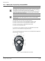
Multimedia Control Panel ShuttlePRO2..................................................60
Dome cameras........................................................................................61
17
17.1
17.1.1
17.1.2
17.1.3
17.2
17.3
17.4
17.5
17.6
17.7
17.8
17.9
17.10
17.11
17.12
17.13
17.14
17.15
17.16
17.16.1
17.16.2
17.16.3
17.16.4
17.16.5
17.16.6
17.16.7
Playback.................................................................................................62
Description of the menus ........................................................................63
Menu File.................................................................................................63
Menu View...............................................................................................63
Menu Database.......................................................................................63
Cash box search .....................................................................................66
Logbook in playback ...............................................................................68
Multi-channel playback............................................................................70
Reference frame for replay .....................................................................71
Audio playback........................................................................................72
Timeline display ......................................................................................73
Database scan ........................................................................................75
Search for changes in videos with SearchMask .....................................75
Triplex operation .....................................................................................77
Logbook...................................................................................................78
Write protection for records.....................................................................79
Recorder control......................................................................................79
Zooming ..................................................................................................80
Printing pictures ......................................................................................80
Export of pictures ....................................................................................80
Generating film sequences .....................................................................81
Burning image sequences to CD/DVD....................................................83
Exporting image sequences to CD/DVD using an integrated DVD burner84
Exporting image sequences to CD/DVD using an external USB burner 84
Writing files of a directory to CD/DVD.....................................................84
Writing film sequences to CD/DVD .........................................................85
Writing multiple film sequences to CD/DVD............................................85
4
Siemens Building Technologies
Fire Safety & Security Products
01.2008
17.16.8
17.17
17.18
Backup ....................................................................................................86
Export of CDM data ................................................................................86
CDM replay .............................................................................................87
18
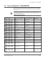
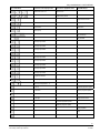
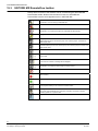
Key combinations in SISTORE MX......................................................89
19
19.1
19.2
19.3
19.4
19.5
19.5.1
19.5.2
19.5.3
19.5.4
19.5.5
19.5.6
19.5.7
19.5.8
19.6
19.7
19.8
19.8.1
19.8.2
19.9
19.10
19.10.1
19.10.2
19.10.3
19.11
19.12
19.13
19.14
19.15
19.16
19.17
19.17.1
19.17.2
19.17.3
19.18
19.19
19.20
SISTORE MX RemoteView ...................................................................93
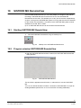
Starting SISTORE MX RemoteView .......................................................93
Program window SISTORE MX RemoteView ........................................93
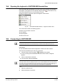
SISTORE MX RemoteView toolbar ........................................................94
Opening the logbook in SISTORE MX RemoteView ..............................95
Connecting to SISTORE MX...................................................................95
Open address book.................................................................................96
Show all...................................................................................................97
Add entry.................................................................................................97
Editing entries .........................................................................................99
Deleting entries .......................................................................................99
Sorting entries .......................................................................................100
Select cameras .....................................................................................100
Searching for a SISTORE MX server ...................................................102
Display live images ...............................................................................103
Multi-monitor mode ...............................................................................103
Virtual guard tour...................................................................................106
Configuring the virtual guard.................................................................106
Starting and terminating the virtual guard .............................................107
Start/stop recording...............................................................................108
SISTORE MX RemoteView alarm list (optional)...................................108
Show alarm details................................................................................108
Acknowledge alarm list entry ................................................................108
Display live image of the camera which triggered the alarm ................109
Connection protocol ..............................................................................109
AVI remote export .................................................................................110
Backup ..................................................................................................110
Evaluation of video sequences in playback mode ................................112
Remote control of alarm outputs...........................................................114
Local revision of existing databases .....................................................114
Remote system reboot..........................................................................114
Configuring the video display area........................................................115
Open and close site plan ......................................................................116
Different views of the site plan ..............................................................117
File transfer ...........................................................................................121
Software update on MX server via SISTORE MX RemoteView...........122
Multi-server mode .................................................................................122
20
20.1
20.2
20.3
20.4
20.4.1
20.4.2
20.4.3
20.4.4
20.5
20.6
20.7
20.8
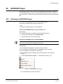
SISTORE Player...................................................................................127
Starting the SISTORE Player................................................................127
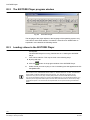
The SISTORE Player program window ................................................128
Loading videos in the SISTORE Player................................................128
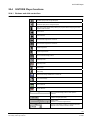
SISTORE Player functions....................................................................129
Buttons and slide controllers.................................................................129
Key combinations..................................................................................131
Zoom function .......................................................................................131
Parameters for displaying video sequences .........................................131
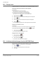
Playing loops.........................................................................................132
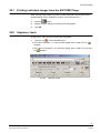
Archiving individual images from the SISTORE Player ........................132
Printing individual images from the SISTORE Player...........................133
Signature check ....................................................................................133
5
Siemens Building Technologies
Fire Safety & Security Products
01.2008
21
Index .....................................................................................................134
6
Siemens Building Technologies
Fire Safety & Security Products
01.2008
Description of functions
1
Description of functions
SISTORE MX is a hybrid video recording system for the surveillance of rooms,
premises, buildings, production workshops, critical public areas or any outdoor
areas where security is important.
SISTORE MX offers the following functions:
– Simultaneous recording of up to 64 cameras, depending on the model
– Simultaneous display of all cameras for live surveillance at the same time as
recording
SISTORE MX easily adapts to your application, both with regard to your various
different alarm triggers such as for instance cameras, light barriers etc., and also in
case of alarms to control your various external devices such as for instance sirens,
alarm systems, lighting etc.
By defining different alarm configurations, you also have the opportunity to adjust
the video recording to the actual surveillance task in question and thereby
maximise the performance of your system.
In addition, SISTORE MX possesses a user administration function. By issuing
different user rights, it allows for each user to have access to certain functions on
an individual basis according to his/her range of tasks; such access may also be
denied to others.
The delivery includes, free of charge, the SISTORE Player program in addition to
the SISTORE MX program itself. SISTORE Player gives you the capability to
replay video recordings or exported AVI sequences.
The delivery also includes SISTORE MX RemoteView. Using SISTORE
RemoteView, you have the opportunity to remote access (via LAN or ISDN) the
system in order to revise the recorded videos and to watch camera pictures live.
Here SISTORE MX RemoteView functions as a client accessing a SISTORE MX
server. When operating SISTORE MX with separate hard disks, SISTORE MX
RemoteView enables you to carry out local playback on an external PC.
7
Siemens Building Technologies
Fire Safety & Security Products
01.2008
Safety
2
Safety
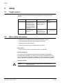
2.1
Target readers
The instructions in this document are designed only for the following target
readers:
2.2
Reader group
Qualification
Activity
Condition of the
product
Operator
Has read and understood
the instructions in the
documentation regarding
operation. No particular
basic training is required,
although some instruction
by technical specialists may
be necessary.
Performs only the
procedures for proper
operation of the product,
device or system.
The product is installed
and set up.
Service personnel
Technical training for
building or electrical
installations.
Checks the product at
regular intervals to
ensure that it is in good
working order, services
the product and repairs it.
Product already in use
and requiring servicing.
Work safety information
– Read the general safety precautions before operating the device.
– Follow all warnings and instructions marked on the device.
– Keep this document for reference.
– Always pass this document on together with the product.
Burn hazard
– Do not touch the housing of the device while it is in operation.
National standards
The products are developed and manufactured according to all applicable
European safety standards. Any national or local safety standards or laws that
apply to the development, design, installation, operation or disposal of a product
must be adhered to in addition to the instructions in the product documentation.
Electrical systems
DANGER
Work on electrical systems should only be performed by trained personnel
under the supervision of a certified electrician in accordance with the
appropriate regulations.
8
Siemens Building Technologies
Fire Safety & Security Products
01.2008
Safety
z Disconnect main control systems from the main power supply before performing
maintenance or repair.
z Check that no voltage is present on components that have been isolated from
the main power supply in this way.
z Use only insulated tools!
z Terminals carrying an external voltage supply must be labelled “DANGER –
external voltage”.
z Power cables to the main device are to be run separately and have a dedicated,
clearly labelled fuse.
z Electrical grounding must meet the customary local safety regulations.
z Battery connections must never be short-circuited and contact with the housing
must be avoided in all cases.
z The appropriate safety measures must be observed when working in explosion
hazard zones.
Installation and setup
z If auxiliary equipment such as a ladder is required for the installation, safe
equipment appropriate to the task in hand must be used.
z If devices from third-party firms are to be operated, the responsible person must
be present.
Changes to the product
Changes to the product and the way it is installed require written permission from
Siemens and the local safety agencies responsible for the site where the device is
in operation.
Components and spare parts
Installed components and spare parts must meet the technical specifications of the
manufacturer. The manufacturer’s original spare parts are guaranteed to do so.
Only fuses with the specified characteristics are to be used.
Condition while the system is in use:
Temperature: 5 to 35 °C.
Please avoid direct sun and shock.
9
Siemens Building Technologies
Fire Safety & Security Products
01.2008
Safety
Disregarding safety regulations
The products are designed for proper use and are checked before delivery to
ensure that they are in good working order. Siemens assumes no liability
whatsoever for damages or bodily injuries resulting from misuse or disregard of the
instructions or hazard information in the documentation.
This applies especially in the case of
z Personal injury or damage resulting from improper use and/or use for purposes
other than those for which the product is intended
z Personal injury or damage resulting from non-observance of the safety
information in the documentation or on the product (labelling).
z Personal injury or damages as a consequence of inadequate maintenance or
failure to perform maintenance.
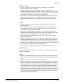
Conventions
When used for operation according to the UVV (accident prevention regulations for
banks), the SISTORE MX must be installed and configured with observance of BGI
819-7 (installation guidelines for optical room surveillance systems).
Important information for observance of "BGI 819-7" guideline
z It is not permissible to hide all cameras; this particularly applies to those in the
counter area.
z Work on the system which interferes with recording may only be carried out
when there is no business at the cash desks, i.e. outside opening hours or
immediately after a holdup.
z A customized system using Microsoft Windows is used for digital image
recording. This system is only available for the SISTORE MX application
software; it cannot be used for other Windows applications.
z To prevent data losses due to power failure, the device should have a self-
contained power supply.
z Performance testing and troubleshooting must be carried out with observance of
BGI 819-7 (testing of optical room surveillance systems).
10
Siemens Building Technologies
Fire Safety & Security Products
01.2008
Safety
2.3
Meaning of the written warning notices
The severity of a hazard is indicated by the following written warning notices.
Signal word
Type of risk
DANGER
Dangerous situation
Death or severe bodily injury may result.
CAUTION
Dangerous situation
Severe bodily injury may result.
WARNING
A dangerous situation can occur
Minor injuries may result.
NOTE
Technical or operating information
Disregarding this information may lead to damage to the product or property in
the product’s vicinity.
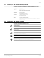
2.4
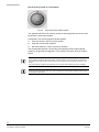
Meaning of the hazard symbols
The nature of the hazard is indicated by icons.
Dangerous situation
Electrical voltage
External voltage
Ground the component before making contact.
Tips and information
Important operating step or action
For example: the system, components or controls must be at zero potential.
11
Siemens Building Technologies
Fire Safety & Security Products
01.2008
Directives and standards
3
Directives and standards
This equipment has been tested and found to comply with the limits for a Class A
digital device, pursuant to Part 15 of the FCC Rules. These limits are designed to
provide reasonable protection against harmful interference when the equipment is
operated in a commercial environment. This equipment generates, uses, and can
radiate radio frequency energy and if not installed and used in accordance with the
Instruction Manual, may cause harmful interference to radio communications.
Operation of this equipment in a residential area is likely to cause harmful
interference, in which case users will be required to correct the interference at their
own expense.
CAUTION
Changes or modifications not expressly approved by the party responsible for compliance could void
the user's authority to operate the equipment.
This class of digital apparatus meets all requirements of the Canadian interferencecausing equipment regulations.
National standards
The products are developed and manufactured according to all applicable
European safety standards. Any national or local safety standards or laws that
apply to the development, design, installation, operation or disposal of a product
must be adhered to in addition to the instructions in the product documentation.
12
Siemens Building Technologies
Fire Safety & Security Products
01.2008
Technical data
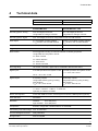
4
Technical data
Recording speed - analog
SISTORE MX 3204
SISTORE MX 3208 - 3232
with 4 video inputs
with 8, 16 or 32 video inputs
SISTORE MX 3204
SISTORE MX 3208 - 3232
max. 50 images per second,
max. 100 images per second,
configurable for analogue cameras
configurable for analogue cameras
Recording speed - digital
max. 100 images per second, configurable for max. 32 LAN cameras
Video inputs
4 x CCVS (BNC sockets) enabled,
1 Vpp/75 Ohm, max. 32 LAN cameras
8/16/32 x CCVS (BNC sockets) enabled,
1 Vpp/75 Ohm, max. 32 LAN cameras
Outputs
1 x VGA, 2 x CCVS (BNC sockets)
1 x VGA, 4 x CCVS (BNC sockets)
Trigger inputs
16 Uin: 5 – 24 V, max. 10 mA
32 Uin: 5 – 24 V, max. 10 mA
Event control
event-triggered recording of individual cameras or camera groups with
configurable time-slot pattern. Events:
z alarm contacts
z motion detection
z Time control
z TCP/IP command
Alarm signalling
via monitor connection, digital output, LAN/WAN to RemoteView station
Digital inputs
4 for AND operations and system control 8 for AND operations and system control
Uin: 5 – 24 V, max. 10 mA
Uin: 5 – 24 V, max. 10 mA
Digital outputs
8 alarm/key outputs,
configurable switching (rising or falling
edge duration)
Uout 5 – 24 V, max. 50 mA
Interfaces
2 x RS485, 1 x LAN, 4 x USB 2.0 (0.5 A), 1 x SCSI,
1 x VGA, 1 x Audio in, 1 x Mic in, 1 x Audio out,
optionally: S0 interface for ISDN
Mouse, PC keyboard
mouse with USB connection, virtual keyboard activated, USB keyboard (optional)
Video standard
PAL/NTSC
Resolution
standard:
352 x 288 pixels,
high resolution: 704 x 288 pixels
Compression
M-JPEG, configurable: variable between 10 and 80 KB
Text overlay in the video image
max. 16 characters
Font and background colours
freely selectable
Storage media
basic unit (E)IDE
16 alarm/key outputs,
configurable switching (rising or falling
edge duration)
Uout 5 – 24 V, max. 50 mA
13
Siemens Building Technologies
Fire Safety & Security Products
01.2008
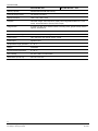
Technical data
SISTORE MX 3204
SISTORE MX 3208 - 3232
Memory capacity
250/500/750/1000 GB data memory
External storage media
via network connection
Display resolution
1024 x 768, 1280 x 1024
Playback
individual images, video sequence (replay rate configurable between 0.1 to 50
times), forward/backward, pause (frozen image)
Image search
by means of date, time, camera number, recording event, graphic activity search,
logbook, Smartsearch
Video display formats
1x1, 2x2, 1 + 5, 3x3, 2 + 8, 4 + 9, 4x4, 6x6 - 4 (32), 7x7 – 1 (48), 8x8 (64)
System self-monitoring function hardware/software watchdog
Power supply
100 – 230 V AC, 50 – 60 Hz, approx. 120 W
Power input
appliance inlet
Temperature range (operation)
5 – 35 °C
Design
embedded
Environmental temperature
5 – 45 °C
Rel. humidity
20 – 80 % without condensation
Dimensions (W x H x D)
430 x 87 x 370 mm
14
Siemens Building Technologies
Fire Safety & Security Products
01.2008
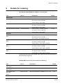
Details for ordering
5
Details for ordering
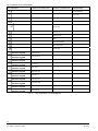
As of Q2 2007 SISTORE MX is available in seven models:
Type
Part no.
Designation
Weight
S24245-F5085-A2
Hybrid recorder, 8 analog cameras,
11.0 kg
Without DVD
SISTORE MX 3208 250/200
32 network cameras, 250 GB,
100 ips analog, 100 ips digital
SISTORE MX 3216 500/200
S24245-F5085-A4
Hybrid recorder, 16 analog cameras,
11.0 kg
32 network cameras, 500 GB,
100 ips analog, 100 ips digital
SISTORE MX 3232 1000/200
S24245-F5085-A6
Hybrid recorder, 32 analog cameras,
11.0 kg
32 network cameras, 1000 GB,
100 ips analog, 100 ips digital
With DVD
SISTORE MX 3204 250/150
DVD
S24245-F5085-A1
Hybrid recorder, 4 analog cameras,
11.0 kg
32 network cameras, 250 GB,
50 ips analog, 100 ips digital, with DVD
SISTORE MX 3208 250/200
DVD
S24245-F5085-A3
Hybrid recorder, 8 analog cameras,
11.0 kg
32 network cameras, 250 GB,
100 ips analog, 100 ips digital, with DVD
SISTORE MX 3216 500/200
DVD
S24245-F5085-A5
Hybrid recorder, 16 analog cameras,
11.0 kg
32 network cameras, 500 GB,
100 ips analog, 100 ips digital, with DVD
SISTORE MX 3232 1000/200
DVD
S24245-F5085-A7
Hybrid recorder, 32 analog cameras,
11.0 kg
32 network cameras, 1000 GB,
100 ips analog, 100 ips digital, with DVD
All SISTORE MX models have enabled video output and SCSI functions and are
delivered without keyboard.
SISTORE MX accessories (not included in the delivery):
Type
Part no.
Designation
Weight
Activation of 4 SISTORE MX
video inputs
S24245-P5097-A4
Enables an additional 4 analog video inputs
./.
Activation of 8 SISTORE MX
video inputs
S24245-P5097-A1
Enables an additional 8 analog video inputs
./.
19“ installation kit for
SISTORE
C24245-A12-D2
Mounting equipment for installation in a 19“ rack
4.0 kg
MX/CX
15
Siemens Building Technologies
Fire Safety & Security Products
01.2008
Details for ordering
Software update to on
S24245-P5097-A5
The memory stick can be used directly on the USB ./.
interface for the update
S24245-F5092-A1
For connection of cash dispensers,
SISTORE MX memory stick
MX multichannel box
(GAA/ATM)
SISTORE MX hard drive
1.2 kg
cash box or access control systems
2GF4811-8CD
For the expansion of SISTORE MX as of V2.50
0.8 kg
S24245-B5093-A1
For the expansion of SISTORE MX as of V2.50
0.8 kg
SISTORE RAID8 2000
S24245-B5108-A1
2 TB RAID system
34.8 kg
SISTORE RAID8 3000
S24245-B5108-A2
3 TB RAID system
38.4 kg
USBOBTO8
2GF4811-8CH
USB-input module – 8 channels with optocoupler
function
./.
USBREL8
2GF4811-8CG
USB output module - 8 channels with relay
function
./.
USBOPTOREL16
2GF4811-8CJ
USB input and output modules with 16
optocoupler inputs and 16 relay outputs
./.
USB ISDN module
2GF4811-8FC
For use on the SISTORE MX
0.8 kg
SISTORE MX USB mouse
A5Q00009353
As a replacement device
SISTORE MX USB keyboard
A5Q00009346
For SISTORE MX without keyboard
External USB DVD burner
GBQ:S80817
For SISTORE MX without internal DVD burner
CMTC1525 TFT monitor
2GF3124-8AA
15-inch TFT colour monitor for CCTV
6.0 kg
CMTC1725 TFT monitor
2GF3125-8AA
17-inch TFT colour monitor for CCTV
6.5 kg
CMTC1925 TFT monitor
2GF3126-8AA
19-inch TFT colour monitor for CCTV
7.0 kg
Interface converter
2GF5505-8AH
Interface converter RS232C/RS485
0.1 kg
Converter model 4855DSR
./.
From roline (please order directly from the
manufacturer)
./.
Converter model USB/RS232
./.
From roline (please order directly from the
manufacturer)
./.
KeBin access reader
./.
From KEBA (please order directly from the
manufacturer)
./.
Miniter access reader
./.
From STM GmbH (please order directly from the
manufacturer)
./.
Multimedia Control Panel
(ShuttlePRO2)
./.
From Contour Design Ltd. (please order directly
from the manufacturer)
./.
expansion kit 250 GByte
SISTORE MX hard drive
expansion kit 500 GByte
RS232C/RS485
The part number will be found on the rating plate on the bottom of the unit.
Fig. 1
Rating label
16
Siemens Building Technologies
Fire Safety & Security Products
01.2008
Scope of delivery
6
Scope of delivery
z SISTORE MX
z Mouse
z Mains cable
z 8 x digital I/O connector (SISTORE MX 3204)
z 14 x digital I/O connector (SISTORE MX 3208 - 3232)
z Activation form
z CD with the SISTORE MX application software and complete documentation
17
Siemens Building Technologies
Fire Safety & Security Products
01.2008
Prerequisites
7
Prerequisites
7.1
Hardware requirements
SISTORE MX integrates a video compression board (or frame grabber) that
features up to 16 (MX 3204) / 32 (MX 3232 - 3208) video inputs, depending on the
model.
SISTORE MX 3204
SISTORE MX 3208 - 3232
4 video inputs
8, 16, 32 video inputs
The video data is stored on local hard disks. Saving on optical CD-R/CD-RW odrr
DVD-R/DVD-RW drives is possible directly from SISTORE MX (see Section
17.16.2: Burning image sequences to CD/DVD).
7.2
Resolution and file format
The files stored by SISTORE MX have the extension .AVI or .k26. The resolution of
the stored images is (by using normal resolution) 352 x 288 pixel and (by using
high resolution) 704 x 288 pixel.
NOTE:
From version 2.35 on, SISTORE MX saves all files as *.k26 files instead of *.avi files. The SISTORE
player makes no difference between these two file types. The *.k26 files can however not be
reproduced using other movie player models (data protection of the SISTORE MX video files).
The user should therefore always copy the file „SISTOREPlayer.exe“ from the Windows directory (e.g.
\Windows) to the target data medium (disk, CD-R/CD-RW, DVD-R/DVD-RW or network drive) using
the Windows explorer. This ensures that the exported files can be reproduced using the SISTORE
player. Alternatively, since Version 2.45, the data can be stored without data protection as *.avi files
which can be played with standard movie player. For detailed information about data protection see
Section 17: Playback.
7.3
Conversion
As of version 2.35, SISTORE MX automatically converts the configurations of the
preceding version to the current version. Nevertheless, we would like to emphasize
that you should check your configuration without fail after an update.
NOTE:
A conversion of older versions (earlier than version 2.35) is not possible. It is also not possible to take
over settings for event-triggered recordings and scenarios from the preceding versions (earlier than
version 2.55). These are deleted during the conversion.
18
Siemens Building Technologies
Fire Safety & Security Products
01.2008
Operating modes
8
Operating modes
There are three operating modes:
z Display mode
z Playback mode
z Configuration mode
8.1
Display mode
After starting SISTORE MX, you will be in display mode. From here, after
successful login to the system, it is possible to access the configuration and
playback modes, insofar as you have the appropriate user authorisation to do so.
“Display mode” is intended for operating or surveillance staff while the system is in
operation. The cameras and all incoming events are displayed and recorded here.
It is also used for flexible live surveillance of all cameras.
8.2
Playback mode
The playback and/or revision of recordings is carried out in this mode. It is based
on an extremely high performance database and allows fast and easy tracking of
received alarms and their respective video sequences with all relevant additional
information. It is also possible to save important pictures in currently used formats
or even whole video sequences as “evidence“. Access to the “playback mode” is
only possible with the “Playback“ user authorisation.
8.3
Configuration mode
All system settings are defined in this mode (please refer to the Configuration
Manual). The opportunity exists to issue user authorisations (see Section 11 User
rights ). The configuration of the system and the “display mode” as well as the
definition of recording modes can be defined here. As recording modes can be
chosen:
z long-time recording with or without motion detection
z event-triggered recording with pre-alarm history and alarm memory.
This ensures that the system can be flexibly adapted to cover the widest possible
range of applications. Access to the “configuration mode” is restricted to users with
the “Configuration“ authorisation.
19
Siemens Building Technologies
Fire Safety & Security Products
01.2008
Getting started
9
Getting started
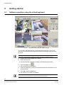
9.1
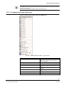
Software operation using the virtual keyboard
Fig. 2
Password entry using the virtual keyboard
As of Q2 2007 SISTORE MX 32xx is delivered without keyboard. Entry of the
characters of the password and parameter setting can be made using the virtual
keyboard.
NOTE
Alternatively, a USB keyboard is available as an option (see Section 5: Details for ordering).
1.
Connect the mouse supplied to a USB port.
2.
Switch the device on.
Î
3.
The SISTORE MX application software will be started automatically.
Click the Login icon
Î
.
The virtual keyboard will appear.
4.
Enter the password by clicking the appropriate letters and characters on the
virtual keyboard.
5.
Click OK or press the Enter key.
Î
The system is now ready for operation.
NOTE
Entries into all other input fields of the system are made in the same manner.
20
Siemens Building Technologies
Fire Safety & Security Products
01.2008
Getting started
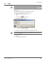
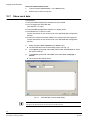
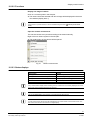
9.2
Login
NOTE:
Without a successful login only the SISTORE MX online help will be available; all other functions will
not be available. Without a successful login it is also not possible to end the program.
Prerequisite
z The SISTORE MX application software has been started.
You have the following options to log into the system:
Select the menu option File -> Login.
1.
– OR –
Click the button
Î
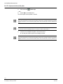
The following dialog box opens:
Fig. 3
2.
in the toolbar.
SISTORE MX login
Enter your user name and password in the appropriate text fields.
NOTE
Your user name and password will be created for you by your administrator. The entry of user name
and password is case-sensitive.
3.
Click OK.
Î
You are logged into the system.
21
Siemens Building Technologies
Fire Safety & Security Products
01.2008
Getting started
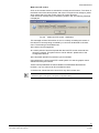
Login via the drop-down menu
1.
Click the arrow to the right of the button
Î
.
A drop-down menu will open.
NOTE
The drop-down menu displays the user names of the last 5 successful registrations. This function is
not available when you log in for the first time.
2.
Select the desired user name.
Î
The SISTORE MX login dialog opens (see Fig. 3).
3.
Enter the password.
4.
Click OK.
Î
You are logged into the system.
NOTE
Every time a user attempts to log into SISTORE MX, the following information is recorded in the
logbook:
z User name
z Time of the login
z Information on whether or not the user was granted access to SISTORE MX
The password is not stored.
22
Siemens Building Technologies
Fire Safety & Security Products
01.2008
Getting started
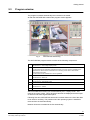
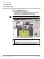
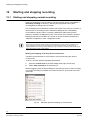
9.3
Program window
The program is started automatically when the device is started.
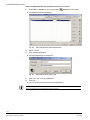
Î
After the SISTORE MX is started the program window appears:
Fig. 4
SISTORE MX start dialog
The SISTORE MX program window consists of the following components:
1
System condition and system information
2
Start frame
See Section 9.7: Video image display modes
The start frame for the application is displayed insofar as no PTZ camera is available or the
registered user does not have authorisation for controlling a PTZ camera. See Section
16.2Camera PTZ control.
The start frame is also available if no user is registered.
3
Status bar
4
Video display area
See Section 9.5: Status bar.
See Section 9.6: Video display area.
5
6
Camera window
SISTORE MX tool bar
See Section 9.4: Toolbar.
7
Menu bar
After SISTORE MX is started you will automatically be in “display mode”. This
mode is the control centre. This is where all cameras are displayed and the output
of all alarm and status signals takes place.
Following first start, SISTORE MX enters all local hard disks on the list of the disks
to be used for recording. The partition where the operating system is installed is
removed from the list automatically.
Network drives are not added to the list automatically.
23
Siemens Building Technologies
Fire Safety & Security Products
01.2008
Getting started
When starting SISTORE MX for the first time, all analogue cameras found by an
automatic check of video inputs should be displayed. If this is not the case, one of
the following reasons is possible:
z an error occurred during the installation of SISTORE MX
z the connection of the cameras to SISTORE MX is faulty (connector not plugged
in properly)
z the camera is not sending any signal
In the first case, you should contact your installer.
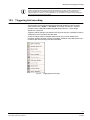
9.4
Toolbar
The software functions can be called up by selecting the appropriate button in the
SISTORE MX toolbar.
Fig. 5
1
SISTORE MX toolbar
Login
See Section 9.2 Login.
2
View logbook
3
Next group
See Section 10.11 Display camera group .
4
Automatic scan
5, 6
Video display modes
See Section 9.7: Video image display modes
7
Show event window
8
Show map
See Section 10.12 Site plan
9
Audio on/off
10
Start recording: Starting the recording
See Section 10.2 Audio on/off
See Section 12 Starting and stopping recording
11
Stop recording: Stopping the recording
See Section 12 Starting and stopping recording
12
Playback: Starting playback.
13
Online help
24
Siemens Building Technologies
Fire Safety & Security Products
01.2008
Getting started
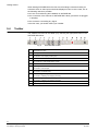
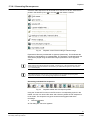
9.5
Status bar
At the bottom of the screen you will find a status bar. You can switch this on or off
with the help of the menu View -> Status line visible/invisible. On the playback or
configuration level, however, the system information is not visible, i.e. in this case
the status line represents the only source of information.
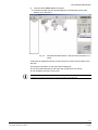
Fig. 6
Status bar
The status bar is divided into 14 fields (see Fig. 6). The meaning of the fields is as
follows:
1
Brief help text to the menus (Windows standard)
2
Number of active connections
3
Connection speed
4
Currently displayed camera group
5
Free storage space of drive(s) being used and the minimum required free space (see below in
this section)
6
Date and time
7
Application running time in hours and minutes
8
Symbol showing whether a camera has detected a motion
Motion detected
No motion detected
9
Symbol showing whether SISTORE MX is currently recording an alarm
Alarm
No alarm
10
Status indication of the tamper detection
Tamper detection active – no tampering detected.
At least one camera has detected a tamper event.
11
Symbol showing a recording activity or a fault in hardware
(blinking green) Hardware OK, recording in progress
(grey) Hardware OK, no recording activity
(red) Fault in hardware
12
ISDN connection.
Channel 1 and Channel 2 are not busy
Channel 1/Channel 2 is busy, connection is set up.
Dial-up of Channel 1/Channel 2
13
Symbol indicating the connection status of the RemoteView.
There is at least one active connection with a RemoteView PC
There is no active connection with a RemoteView PC
14
Login/logout symbol showing the user status
User logged in
No user logged in
25
Siemens Building Technologies
Fire Safety & Security Products
01.2008
Getting started
The available disk capacity is shown in four stages in the status line, two of these
are shown as a graph display.
Stage 1:
The disk capacity which is already occupied is shown as a percentage
in the form of a blue bar.
Stage 2:
As stage 1, but showing the estimated remaining recording time. This is
an estimate because the system does not display the actual remaining
recording time but, instead, measures the data volume that can still be
saved and displays it as an estimated available remaining recording
time. The system uses the actual settings (frame rate, image size) as a
basis for this estimate.
Stage 3:
Shows in text form the designation of the hard disk where current
recording is taking place, the disk's available capacity and its maximum
capacity.
Stage 4:
Shows in text form the available capacity and the maximum capacity of
all hard disks authorised for recording.
The display form set last is stored and used automatically again when SISTORE
MX is restarted. This does not apply to SISTORE MX RemoteView.
RemoteView status displays
There are several server-related status displays on the RemoteView. In multiserver mode, the server whose status is to be displayed must be selected in the list
of cameras.
The status displays always relate to the server that is associated with the selected
camera.
The server-related status displays include:
z Time
z Alarm outputs
z HDD capacity indicator
z Recording duration
z Start/stop of recording
Global status displays for all servers include:
z Motion
z Alarm
z Loss of video
z Camera tamper
z Error
z Connection
26
Siemens Building Technologies
Fire Safety & Security Products
01.2008
Getting started
9.6
Video display area
In display mode all camera pictures are each located within one window. Each
window has a pre-set size and position. The number of visible camera windows
depends on the configuration and the chosen order of the windows. Only those
cameras are displayed which have been configured in the configuration mode
and released for display. The name of the camera, date and time may also be
displayed within the camera picture. Position and colour for these text titles can be
set in the configuration mode.
Right-clicking on a camera window will open the appropriate context menu. This
context menu offers additional options.
Fig. 7
Context menu in the video display area
27
Siemens Building Technologies
Fire Safety & Security Products
01.2008
Getting started
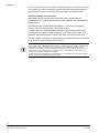
9.6.1
Toggle video display area
By selecting View -> Display off in the display mode you can switch the video
display area on and off even if a user is currently logged on.
Prerequisite:
z You are logged into SISTORE MX and the display mode is opened.
1.
Select Display off or Display on in the View menu .
Î
The video display area is switched off or on.
Fig. 8
"View" menu
28
Siemens Building Technologies
Fire Safety & Security Products
01.2008
Getting started
9.6.2
Toggle full screen mode
Each camera window can be enlarged.
1.
Right-click on the corresponding video image in the video display area.
Î
The context menu will open.
Select Full screen in the context menu.
2.
– OR –
Double click the left mouse button on the corresponding video image.
Î
The video image is displayed in full screen mode.
Return to normal screen:
1.
Double click the left mouse button on the camera picture displayed in full
screen mode.
Î
The video image is displayed in the normal screen mode.
NOTE
The size of the video image is limited by the size of the camera window. If the picture supplied by the
camera is larger than the display area, it will be scaled down to an appropriate size so it can be
displayed in the camera window. Only one camera window can be enlarged at a time.
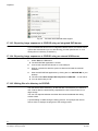
9.7
Video image display modes
You can choose how many camera windows will be displayed simultaneously in
the video display area.
The camera windows are displayed equally in a 1-, 4-, 9-, 16-, 25-, 32- and 64-split.
Using the 6-, 7-, 10- and 13-split, the windows are displayed in different sizes.
NOTE
Adjustments are possible depending on the respective hardware being used; for instance if your HVR
systems is an 8-channel model, then only 8 cameras will be displayed in the 9-split display.
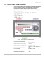
Different acronyms are displayed in the video frame at top left to identify the mode
of operation (see Fig. 9).
Fig. 9
SISTORE MX camera window
29
Siemens Building Technologies
Fire Safety & Security Products
01.2008
Getting started
The meaning of the acronyms is as follows:
Acronym
9.7.1
Meaning
STOP
Camera image is only displayed
DET
Motion detection is activated
REC
Camera is recording
PTZ (yellow)
The camera has pan/tilt and zoom functions and is currently active. The window of
an active PTZ camera has yellow edging.
PTZ (grey)
The camera has PTZ function, but is not active, i.e. the PTZ function is not being
applied to this camera.
DISP
The live image of a LAN camera is displayed.
Changing the number of cameras shown
Prerequisites:
z The SISTORE MX application software has been started.
z You are logged into SISTORE MX..
(See Section 9.2: Login)
z
Select the desired menu option X cameras in the View menu.
1.
Î
The selected number of cameras are shown in the video display area.
Increase or reduce the number of cameras shown
1.
Click either
Î
or
in the toolbar.
The number of cameras shown is increased or reduced.
The window split is defined within the “configuration mode”, which is automatically
active after starting SISTORE MX.
9.7.2
Enlarging camera windows
Each camera window can be enlarged and displayed centrally.
1.
Right-click on the corresponding video image in the video display area.
Î
The context menu will open.
Select Full screen in the context menu.
2.
– OR –
Double click the left mouse button on the corresponding video image.
Î
The video image is displayed in full screen mode.
Return to normal screen
1.
Double click the left mouse button on the camera picture displayed in full
screen mode.
Î
The video image is displayed in the normal screen mode.
NOTE
The size of the video image is limited by the size of the camera window. If the picture supplied by the
camera is larger than the display area, it will be scaled down to an appropriate size so it can be
displayed in the camera window. Only one camera window can be enlarged at a time.
30
Siemens Building Technologies
Fire Safety & Security Products
01.2008
Getting started
9.7.3
Regrouping camera windows
You can regroup the camera windows as desired.
Prerequisites:
z The SISTORE MX application software has been started.
z You are logged into SISTORE MX..
(See Section 9.2: Login)
z The video display area is opened.
(See Section 9.6.1: Toggle video display area)
z
1.
Click on the desired camera window.
2.
Drag the camera picture to the desired window while holding the left mouse
button pressed.
Î
The positions of the two camera windows are interchanged.
9.8
System condition and system information.
9.8.1
Showing / hiding system information
Prerequisites:
z The SISTORE MX application software has been started.
z You are logged into SISTORE MX..
(See Section 9.2: Login)
z The SISTORE MX application software is in display mode.
Click the option System information visible in the View menu.
1.
Î
9.8.2
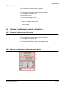
The system information is either shown or hidden (see Fig. 10).
Meaning of the displays in the system information
Fig. 10
SISTORE MX system information
31
Siemens Building Technologies
Fire Safety & Security Products
01.2008
Getting started
1
Shows the current time and date
2
LEDs indicating the status of the alarm outputs
(see Tab. 2)
3
Various status displays
(see Tab. 3)
4
Indication of the free hard disk capacity
(see Fig. 11)
Tab. 1
Sections of the SISTORE MX system information
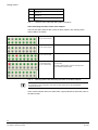
LEDs indicating the status of the alarm outputs
There is one status LED for each of the 16 alarm outputs. The meaning of the
status LEDs is as follows:
Grey
(top row, 2nd from left)
The alarm output is not configured and is not being used.
Green
(top row, 2nd from left)
The alarm output is inactive.
Red
(top row, 3rd from left)
The alarm output is active.
Red/Green surrounded
by a rectangular field
(top row, 1st from left):
This alarm output can be activated or deactivated by the
user manually.
Red means that the alarm output is currently active.
Green indicates inactive status.
Tab. 2
Meaning of the LEDs indicating the status of the alarm outputs
NOTE
For information on the configuration of the alarm outputs please refer to the SISTORE MX
Configuration Manual.
If the mouse indicator rests on a status LED, a popup Quickinfo shows the name of
the alarm output.
32
Siemens Building Technologies
Fire Safety & Security Products
01.2008
Getting started
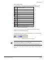
Various status displays
The section below the LEDs indicating the status of the alarm outputs contains
various status displays. The meaning of these status displays is as follows:
No recording at the moment
Min. one camera is recording
No movement
Movement detected
No alarm
Alarm
Camera connection OK
Loss of video
Tampering detected
Tampering and a camera breakdown detected
System condition OK
System error
No active connection to a SISTORE MX client
Connection to a SISTORE MX client is online
Tab. 3
Meaning of the status displays
If the mouse indicator rests on a status display, a Quickinfo window pops up.
Indication of the free hard disk capacity
Underneath the status displays, there is a graphic display of the available capacity
of the hard disks enabled for recording.
Fig. 11
Indication of the free hard disk capacity
NOTE
When the system is not recording, e.g. in the configuration mode, the display shows the hard disk
capacity that is actually engaged and the free hard disk capacity.
When the recording operation is started, the system reserves additional hard disk capacity for about 12 minutes; the percentage of the engaged hard disk capacity will therefore be slightly increased.
If the mouse indicator rests on the hard disk capacity display, a Quickinfo window
pops up.
33
Siemens Building Technologies
Fire Safety & Security Products
01.2008
Display mode functions
10
Display mode functions
10.1
Change password
Prerequisite:
z You have been granted permission to change your password by an
administrator or admin user.
1.
Select New password in the File menu.
Î
The Password modification dialog opens (see Fig. 12).
Fig. 12
Password modification dialog
2.
First enter the old password and then enter the new one into the field below.
3.
Enter the new password once more into the Confirmation field.
4.
Click OK.
34
Siemens Building Technologies
Fire Safety & Security Products
01.2008
Display mode functions
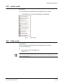
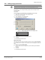
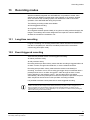
10.2
Audio on/off
Prerequisite:
z You are logged into SISTORE MX and the display mode is opened.
1.
In the Action menu, select the option Audio on or Audio off.
Fig. 13
10.3
"Action" menu
Clear errors
Prerequisites:
z You are logged into SISTORE MX and the display mode is opened.
z There is a malfunction.
z
1.
Select Clear errors in the Action menu.
(See Fig. 13.)
NOTE
Errors include for instance a defective hard disk or the untimely termination of SISTORE MX (e.g. as a
result of a power failure, etc.).
35
Siemens Building Technologies
Fire Safety & Security Products
01.2008
Display mode functions
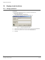
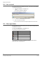
10.4
User comment
You can add comments to the logbook at any time. This function is also available
in SISTORE MX RemoteView.
1.
Select User comment in the Action menu.
– OR –
Press the key combination <ALT+ L>.
Î
The following dialog box will appear:
Fig. 14
2.
Enter a comment and click OK.
Î
10.5
SISTORE MX logbook comment
The comment will be saved to the logbook together with the user name.
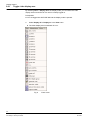
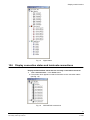
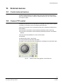
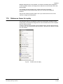
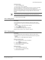
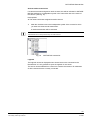
Show signal states
The signal states of the cameras, alarm inputs, alarm outputs and digital inputs can
be displayed on the server.
To do this select Signal state… in the Action menu.
The meaning of the symbols is as follows:
Symbol
Meaning
Motion detected by camera
Signal loss on camera
Tamper event detected by camera
(LED light-red)
Active alarm input
(LED lightgreen)
Active alarm output
(LED lightblue)
Active digital input
Alarm outputs that are remotely controllable can be activated/deactivated by
double clicking the corresponding LED.
36
Siemens Building Technologies
Fire Safety & Security Products
01.2008
Display mode functions
Fig. 15
10.6
Signal status
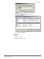
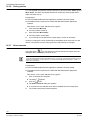
Display connection status and terminate connections
Display the RemoteView clients that are currently connected to the server
1.
Select Connect state… in the Action menu.
Î
The window which appears contains information on the connection status
(see Fig. 16).
Fig. 16
SISTORE MX connections
37
Siemens Building Technologies
Fire Safety & Security Products
01.2008
Display mode functions
Disconnect RemoteView clients
10.7
1.
To do this select Connect state… in the Action menu.
2.
Double click an active connection.
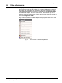
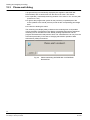
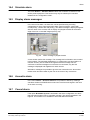
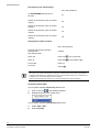
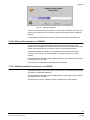
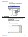
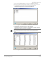
Show cash data
Prerequisites:
z The SISTORE MX application software has been started.
z You are logged into SISTORE MX..
(See Section 9.2: Login)
z The SISTORE MX application software is in display mode.
z SISTORE MX is in cash box mode.
Further information on this can be found in the SISTORE MX Configuration
Manual.
z At least one cash box has been added to the cash box list and configured.
Further information on this can be found in the SISTORE MX Configuration
Manual.
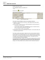
1.
Select the option Show cashdata in the Action menu.
Î
The SISTORE MX cash box data dialog opens (see Fig. 17).
2.
In the Options group field under Cash, select either all cash boxes or select
the desired cash box.
3.
In the Options group field under Data, select either Raw, Codepage or
Filtered.
Î
The cash box data will be shown.
Fig. 17
SISTORE MX cash box data dialog
NOTE
Changes to the filter settings will be seen with the next data received.
38
Siemens Building Technologies
Fire Safety & Security Products
01.2008
Display mode functions
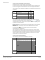
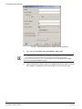
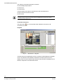
10.8
Setting image parameters
NOTE
It depends on the type of camera whether or not and which image parameters can be set.
In this dialog, you can change the display quality of the live images and the
recording quality.
Prerequisite:
z You are logged into SISTORE MX and the display mode is opened.
1.
Right-click on the live image of the required camera.
Î
2.
The context menu will open.
Select Settings in the context menu.
Î
The following window will appear:
Fig. 18
Setting image parameters in the "display mode"
Camera parameters
1
Brightness
2
Contrast
3
Colour saturation
3.
Move the slide controls to the desired positions.
4.
Click OK.
Î
The settings have been saved.
Black & white mode
When black-and-white mode is activated, the slide control for colour saturation
(3) is disabled and the images of the selected camera are displayed in black and
white.
1.
Mark the checkbox black & white.
2.
Move the slide controls for brightness (1) and contrast (2) to the desired
positions.
3.
Click OK.
Î
The settings have been saved.
39
Siemens Building Technologies
Fire Safety & Security Products
01.2008
Display mode functions
Reset default image parameters
Clicking the button Default image parameters resets all image parameter to their
default values.
1.
Click on Default image parameters.
2.
Click OK.
Î
10.9
The settings have been saved.
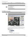
Display reference image
A reference frame documents the setting of a camera (frame cut-out) at the time
when a reference frame was generated. Following installation and alignment of the
camera, the displayed reference frame section can be held and compared at any
time with the camera's current display locally on the server or by remote access
with SISTORE MX RemoteView.
Generate reference image
1.
Select the menu sequence Administration -> Configuration -> Camera.
Î
Î
The camera configuration dialog appears.
The system automatically generates a camera frame and saves this under a
preset name. The frames are stored in the application's main directory (e.g.
C:\Programs\SIEMENS\ SISTORE) under the name camrefx.jgp, where x
stands for the camera number.
Display reference image
Displaying a saved reference frame is possible both on the server as well as with
SISTORE MX RemoteView.
Prerequisite:
z The user has „Replay“ and „Display“ authorization.
Additional prerequisites for SISTORE MX RemoteView:
z The PC is connected to a server.
z The live image of the camera is displayed.
1.
Right-click on the image of the required camera.
Î
2.
A context menu will be opened.
Select Show reference frame from the context menu.
Î
The reference image will now be displayed.
40
Siemens Building Technologies
Fire Safety & Security Products
01.2008
Display mode functions
Fig. 19
Display reference image
The menu option remains inactive if no reference frame has been stored or the
user does not have adequate authority.
On SISTORE MX RemoteView, this menu option is always enabled if the user has
authorisation to display a reference frame. If no reference image has been saved
for the selected camera, an information message is displayed.
10.10 Output of video image on analog monitor
Each video image can be displayed on an analog monitor provided that it was
captured by an analog camera. This can be done by clicking the right mouse
button being in the corresponding camera picture and then selecting „Monitor“ from
the context menu. The automatic output of all camera pictures on an analogue
monitor can be activated or deactivated via the menu View -> Cameras on
monitor, or by selecting the appropriate button on the toolbar.
If an alarm occurs where the images of a specific camera are to be switched to the
monitor in compliance with configuration, that camera has priority over manual
selection. The automatic picture sequence is interrupted for the duration of event.
10.11 Display camera group
If more cameras are released for display than can be displayed simultaneously in a
multiple split screen, all cameras are divided into groups. SISTORE MX defines
these groups independently. The first n camera windows are located in Group 1,
the last camera windows to be displayed are in the last group. The groups may be
switched through either manually or in an automatic sequence. The groups are
shown in order, with the first group being shown again after the last group.
The selection of either manual or automatic switching through is carried out via the
menu View -> Next Display Group or Automatic Scan, or directly by selecting
the appropriate button in the toolbar. During the enlarged display of a window,
switching through camera groups is not possible.
41
Siemens Building Technologies
Fire Safety & Security Products
01.2008
Display mode functions
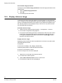
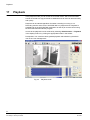
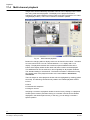
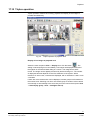
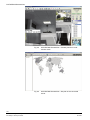
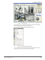
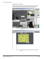
10.12 Site plan
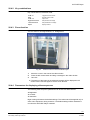
10.12.1 Display modes
Single-monitor mode
1.
Click the button
Î
Show map in the toolbar.
The display window is split horizontally.
In the top section, 1 large and 4 small windows are displayed. In the bottom
section, the site plan is displayed as configured (see Fig. 20).
This splitting of the screen is predefined and cannot be changed.
NOTE
The event view window (1) can be opened at any time by clicking the button
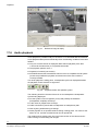
Fig. 20
1
Show event window.
Display site plan in single-monitor mode
Event view
The video image of the camera that was selected in the site plan will be displayed in this area. In
our example, the camera has been tampered with by spraying on paint.
2
In this area, 4 video images are displayed simultaneously. Depending on the number of
cameras that have been configured you can view further camera pictures by either clicking the
button
3
Next group or by selecting the menu sequence View Æ Next display group.
In this area the site plan is displayed as configured.
42
Siemens Building Technologies
Fire Safety & Security Products
01.2008
Display mode functions
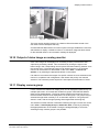
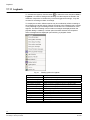
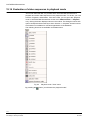
10.12.2 Functions
Display live image of camera
Click on a camera symbol in the site plan.
Î
The camera has been selected and its live image will be displayed in the event
view window (display area 1).
NOTE
If the camera is a pan/tilt camera, it can be orientated using the button
(PTZ).
Camera pan tilt zoom
Open the camera context menu
The camera context menu permits recording to be started manually.
Right-click on a camera symbol in the site plan.
Î
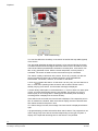
The context menu of the camera will be opened:
Fig. 21
Camera context menu
10.12.3 Status displays
Status display
Meaning
Blinking green frame around a live image.
Motion is being recorded.
Blinking red frame around a live image.
Alarm recording is taking place.
Blinking red frame around an alarm input.
The alarm input has been triggered.
Green frame around an alarm output.
The alarm output has been activated.
NOTE
If any of these status display actions is taking place on a level that is not currently displayed, the name
of the level is shown flashing red in the tree structure.
NOTE
The function Show map is also available on the SISTORE MX RemoteView.
NOTE
In multi-monitor mode, the site plan will be displayed in full screen format on the second monitor. The
first monitor will continue to be used for live image display.
43
Siemens Building Technologies
Fire Safety & Security Products
01.2008
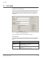
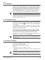
User rights
11
User rights
Persons without user rights have no access to SISTORE MX. User rights can be
configured in the „User management“.
Each person who will be working with SISTORE MX will be defined as a user and
assigned user rights. Only administrators and persons with user administration
rights can create and delete users or assign and change user authorisations. To
assign or delete rights, a user must at least have the same or a higher level of
authorisation.
Fig. 22
User data and user rights
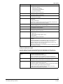
The following tables give an overview of the different user rights:
Global user rights
Global rights are user rights that apply to all cameras. They cannot be assigned to
a user only for particular cameras. The following table describes the global user
rights.
Authorisation
Description
Administration
z Configure all system settings
Installation
z Configure system settings, with restrictions
Configuration
z Create, delete user and grant permissions
z Set up user interface
z Configure hardware components
User management
z Create new users
z Delete users
z Change the authorisations of existing users
44
Siemens Building Technologies
Fire Safety & Security Products
01.2008
User rights
Authorisation
Description
Database
z Process the database during playback, e.g.:
–
Backup the database
–
Regenerate the database
–
Check and repair the database
–
Re-index the database
Prerequisite: Playback authorisation
Delete
z Delete message and recorded sequences
Prerequisite: Playback authorisation
Start/Stop
z Start, stop and terminate recording
z Terminate SISTORE MX
Remote control
z Activate and deactivate alarm outputs either locally at the server or via
RemoteView
z Control PTZ camera
Prerequisite: The alarm outputs have been appropriately configured (see
Section 19.15: Remote control of alarm outputs).
Remote access
z Log on to the system via SISTORE MX RemoteView
z Remote maintenance and remote surveillance
Playback
z Prerequisite for camera-specific playback authorisation.
z Prerequisite for audio playback
Audio playback
z Play audio recordings
Prerequisite: Playback authorisation
Export
Export and backup recordings, e.g.:
z Create AVIs
z Create individual images (BMP or JPG)
z Print pictures
Prerequisite: Playback authorisation
CDM search
z Start CDM search when both banking mode and CDM system are
activated
Playback authorisation is not mandatory for this. A user who has CDM
search authorisation without playback authorisation can switch to
playback mode but he can only carry out CDM search functions. The
logbook, for instance, will not be displayed.
CDM search authorisation can be assigned in the user configuration when
banking mode is activated.
Camera-related user rights
Camera-related user rights are rights that can be assigned to a user only for
specific cameras. Camera-related user rights are described in the table below.
Authorisation
Description
Display
z View the live images of a camera
DISPLAY is a camera-related authorisation
DISPLAY authorisation is not necessary to play the recordings of a
camera. The camera-related playback authorisation is sufficient for this.
PTZ
z Control a PTZ camera
Prerequisite: DISPLAY authorisation for the particular camera.
Playback
z Play the recordings of a camera
Prerequisite: Global playback authorisation
This does not apply to cash dispenser cameras and cash box cameras.
For these cameras, global search rights are required.
z Start cash box search (activated cash box system). This is only
possible when banking mode is deactivated.
45
Siemens Building Technologies
Fire Safety & Security Products
01.2008
Starting and stopping recording
12
Starting and stopping recording
12.1
Starting and stopping normal recording
Starting and stopping of the recording is carried out either via the menu Action ->
Start/Stop recording or directly by selecting the appropriate button (Start
recording/Stop recording) from the toolbar.
The recording action is identified by REC in the picture of the camera in question. If
cameras are not recording but are nonetheless displayed, this is indicated by
STOP within the picture. When a camera is defined as video sensor (motion
detector), movement is displayed by DET in the picture of the camera in question.
Displaying the camera condition as a symbol or as text must be activated in the
“hardware configuration“ of the “configuration mode“.
NOTE
Please note that pre-alarm images will be saved permanently only after an alarm is triggered. If no
alarm is triggered, then the pre-alarm images will not be saved permanently. An alarm may be
triggered either by an event (e.g. motion detection) or by an operator, for instance when pressing the
alarm button during or after a bank robbery.
Starting and stopping recording via the context menu
Cameras can be switched from live image to record mode using the camera
context menu.
To do so, the user requires Start/Stop authorisation.
1.
Open the context menu in the video display area (right mouse-click).
2.
Select Start recording in the context menu.
Manual triggering uses the same settings for recording as set for motion recording.
If no motion recording is installed, the camera records for 10 seconds at the max.
frame rate.
Fig. 23
Manually operated recording via context menu
46
Siemens Building Technologies
Fire Safety & Security Products
01.2008
Starting and stopping recording
NOTE
Please note that pre-alarm images will be saved permanently only after an alarm is triggered. If no
alarm is triggered, then the pre-alarm images will not be saved permanently. An alarm may be
triggered either by an event (e.g. motion detection) or by an operator, for instance when pressing the
alarm button during or after a bank robbery.
12.2
Triggering trial recording
Trial recording can be triggered with activated bank operation in the recording
mode via the menu Action -> Test alarm. As a result, all cameras – with the
exception of the CDM (Cash Dispensing Machine) cameras – record image
sequences of 5 frames.
Triggering trial recordings is recorded in the log book so that it is possible to search
selectively for trial recordings at a later date.
As the recordings must be available permanently, they are not deleted if the
recording capacity has been used up completely. A deletion only takes place if the
number of pre-set recordings has been exceeded.
Fig. 24
Triggering test recording
47
Siemens Building Technologies
Fire Safety & Security Products
01.2008
Starting and stopping recording
12.3
Please-wait dialog
A progress dialog is automatically displayed (also applies to SISTORE MX
RemoteView!) after a certain time from the start of an action. This shows:
z the expected (= estimated) remaining duration of an action in min. and sec (with
precision to 5 sec)
z a light to dark progress bar symbol for the previously completed part of the
action (relative to the overall process) as well as the corresponding percentage
data
z a button for aborting the action.
The remaining time display always relates to the remaining time for all parallel
running activities. Fluctuations in the display are possible because the estimated
remaining time is calculated from the already existing elapsed time and the
progress achieved within that period of time. The calculated time can vary from the
actual time particularly in the case of changing transmission speeds of data
transmission (ISDN) connections.
Fig. 25
Please-wait dialog SISTORE MX / SISTORE MX
RemoteView
48
Siemens Building Technologies
Fire Safety & Security Products
01.2008
Recording modes
13
Recording modes
With the hardware integrated into SISTORE MX, it is possible to record video
sequences from different cameras when using network or IP cameras. Signals
which are fed into the recording system from outside are used to control the
operation of the SISTORE MX during this process.
The following recording modes are available:
z Event-triggered recording
z Long-time recording
All configured cameras operate initially in long-time recording mode and supply live
images. Time settings and events assigned to the respective cameras determine
whether the cameras are recorded or not.
13.1
Long-time recording
Long-time recording is a recording mode where videos are saved on the hard disk
until this is completely full. After that, the oldest pictures will be overwritten
continuously (time lapse mode).
13.2
Event-triggered recording
There are two possible modes of event-triggered recording:
z without pre-alarm history
z with pre-alarm history
Recording without pre-alarm history means that the recording is triggered either via
an alarm contact, through motion detection, or via the software interface.
Recording with pre-alarm history means that the camera must already be
recording. If no alarm occurs, the recording (pre-trigger time) is overwritten after a
preset period of time. If an alarm is triggered - either through an alarm contact,
motion detection or the software control -, the post-alarm time is recorded
automatically. When this preset period of time has expired, the pre-alarm and postalarm sequences are saved and a new pre-alarm recording is started.
It is possible to activate a write protection for event-triggered recording.
NOTE
Please note that pre-alarm images will be saved permanently only after an alarm is triggered. If no
alarm is triggered, then the pre-alarm images will not be saved permanently. An alarm may be
triggered either by an event (e.g. motion detection) or by an operator, for instance when pressing the
alarm button during or after a bank robbery.
49
Siemens Building Technologies
Fire Safety & Security Products
01.2008
Alarm
14
Alarm
14.1
Alarm input (detector )
An alarm input is typically a trigger input of the optocoupler board hardware. An
alarm input is being triggered by an external signal on which a record can be
started.
Each camera is available as a further alarm detector in conjunction with the motion
detection of a camera.
NOTE:
Referring to the configuration, alarm inputs as for example light barriers, or cameras with activated
motion detection can also be understood as alarm detectors
14.2
.
Motion detection (camera as video sensor)
The last picture of a camera is constantly being compared with the current picture
of the same camera. If there is a change in the picture content in a pre-set manner,
SISTORE MX recognises a movement in the picture. This process is called "Motion
Detection" and can be activated for each individual camera.
Motion detection can be used to activate an alarm record and/or record the picture
from a camera only if there is a change in the picture's content. In the first case the
camera itself is being used as an alarm detector also. Considerably less storage
space is required in the case of the latter because only those pictures are saved
where there has been a change in the content of the picture.
Parameters for the motion detection have to be adjusted separately for each
camera. In addition, it is also possible to define sections of the video picture where
motion detection should not or should only be carried out. This enables movements
to be ignored, e.g. movement of trees caused by wind and particular attention to be
given to areas of special interest.
14.3
In the event of an alarm
SISTORE MX checks whether there is a recording configuration for a camera for
the signalled event. If this is the case, recording is started in accordance with the
stored configuration.
If several events occur at the same time which would result in recording with the
same camera, SISTORE MX decides on the further procedure according to the
stored recording configuration. The following rules apply in this case:
z for recordings in the same recording mode (e.g. motion recordings), current
recording continues until all events have been processed;
z long-term recordings are interrupted by a movement or alarm contact;
z motion recordings are interrupted by an alarm contact;
z alarm recordings with normal priority are interrupted by an alarm contact with
raid priority.
z Recordings are recorded in the logbook and stored in a database if the option
"logbook entry" has been activated.
50
Siemens Building Technologies
Fire Safety & Security Products
01.2008
Alarm
14.4
Simulate alarm
The menu Action -> Simulate Alarm enables the simulation of alarms for test
and/or practice purposes. This function may only be called up if it has been
released in the “configuration mode".
14.5
Display alarm messages
In the event of an alarm, an alarm text can be specified using recording
configuration for each camera and each alarm type (movement, contact with
normal priority, contact with raid priority). This alarm message is displayed together
with the name of the camera, both in display and playback modes at the bottom
edge of the live or recorded images (see Fig. 26).
Fig. 26
Alarm message in playback mode
A user should confirm this message. The message and confirmation are recorded
in the logbook. The message disappears if no confirmation is received within 15
minutes. An entry is then made in the logbook that the message was not
confirmed. If several messages occur that are not confirmed, only the first
message is displayed and registered for each camera.
With alarm messages it is possible to give the user instructions etc. about what
further action should be taken by the user in the event of any such alarm.
14.6
Acoustic alarm
In the menu Action -> Acoustic alarm on it is possible to define by marking a
checkbox whether SISTORE MX is to send out a brief acoustic signal in the case
of an alarm occurring.
14.7
Cancel alarm
If the option Breakable by user is activated in the alarm configuration, an alarm
that has been triggered can be cancelled manually. This will be registered in the
logbook. This function is not available in SISTORE MX RemoteView.
51
Siemens Building Technologies
Fire Safety & Security Products
01.2008
Tamper detection
15
Tamper detection
With the help of the automatic tamper detection – which is possible with analog
and IP cameras – it is possible to detect turning, dazzling and covering. If
tampering is detected, SISTOR MX reports the tampering on the screen and
makes an entry in the logbook. In addition, an e-mail can be sent and a switch
output activated.
For tamper detection, first of all stipulate a detection range (specific range of a
video image) in the video image. Any change in the video image within this detection range is then registered. An alarm can then be emitted, depending on the
settings for detection parameters.
NOTE:
You can stipulate several detection ranges per video input (live image).
NOTE:
For tamper detection, the detection range should always lie within an image section where generally
there are only a few image changes and where a lot of non-changing edges are to be seen. Variations
in the image, caused by tampering with the camera (camera was moved or covered), can thus easily
be detected.
Acknowledge tamper alarms
The menu function Action -> Confirm sabotage allows you to acknowledge
tamper alarms.
52
Siemens Building Technologies
Fire Safety & Security Products
01.2008
External devices
16
External devices
16.1
Control external devices
An alarm output (actuator) is a digital output of the optocoupler board hardware
which can be used in order to control an external device (e.g. siren, alarm system,
door opener, lights).
16.2
Camera PTZ control
Cameras with pan-tilt-zoom control that are connected to a serial interface (RS232
or RS485 via converter) can be controlled by SISTORE MX.
Several PTZ cameras can be connected as long as the following conditions have
been fulfilled:
z All cameras connected to a serial interface (COM-Port) use the same log.
z All cameras connected to a serial interface (COM-Port) have their own RS485
address.
There are several possibilities to control a PTZ camera:
z Keyboard
z Standard PC joystick / Jog Shuttle
z Control panels CKA 4810 and CKA 4820
z Graphic control elements that are displayed in the dialog bar at the bottom right
Fig. 27
Camera control using graphic control elements
53
Siemens Building Technologies
Fire Safety & Security Products
01.2008
External devices
Camera control using graphic control elements
Prerequisite for the use of the graphic control elements:
z The PTZ camera has been configured and initialised correctly (COM Port free)
z The user is logged on and has "Remote control" and "Display" authorisations
The fact that the control elements are displayed is no guarantee that the camera is
functioning.
Key
Function
Motion
left, right, up, down, up right, down right,
up left, down left
Zoom
in
Travel keys
(arrows)
out
Focus
far
near
The auto-focus mode is activated again automatically with a pan-tilt command.
Under the PTZ control element, there is a selection list
where all
configured positions (max. 32) are listed with position names. The system goes to
a position if it has been selected.
Movement to the first 5 stored set positions is possible using the control elements
to
. The position names are also displayed with these control
elements.
Pushing the button , the PTZ camera will move to the stored position
automatically in an adjustable time.
The PTZ symbol is bordered in yellow in the live image of the camera currently
being operated by the control system and the window is given a yellow surround.
Non-active PTZ cameras are marked with a grey PTZ symbol. If several cameras
can be controlled, a click with the left mouse button in the window of a camera
activates the PTZ control for that camera.
Camera control using the keyboard
The following key commands are available for PTZ control:
Key
Function
Motion
left, right, up, down
can be used with the number pad switched off: (Num
Lock off)
Zoom
Focus
Cursor
keys
up left
7
up
8
up right
9
left
4
centre
5
right
6
down-left
1
down
2
down-right
3
in
+
out
-
far
0
near
,
54
Siemens Building Technologies
Fire Safety & Security Products
01.2008
External devices
Multi-user PTZ control
Click on the camera window to activate the camera control functions. The colour of
the frame around the camera picture and of the PTZ symbol now change to yellow,
which means that you have control of the PTZ control functions.
If the camera is currently being controlled by another user, the following message
is displayed:
Fig. 28
Multi-user PTZ control - Notification
This message contains information on who is currently controlling the camera. If
the camera is currently being controlled by a user it will be blocked for all other
users. The blocking is terminated when ...
z the other user has logged off.
z a certain period of time has expired after the last PTZ control command was
sent to the camera. This period of time can be defined - please refer to the
Configuration Manual.
z the automatic preset PTZ positions cycle is activated
Users without any control of the PTZ control system can see the graphic control
elements but they are inactive.
These control possibilities are also available in SISTORE MX RemoteView.
However, only one camera can be controlled at a time.
A remote user cannot take over control from any other remote user.
NOTE:
Activate the option „Auto Logout“ in the system configuration dialog.
55
Siemens Building Technologies
Fire Safety & Security Products
01.2008
External devices
Set the moving speed of a PTZ camera
Fig. 29
PTZ control with medium speed
The speed at which the PTZ camera can be moved using either the mouse or the
keyboard is continuously variable.
Prerequisite: The camera supports variable speeds.
1.
Click the red dot in the PTZ control symbol.
2.
Keep the mouse button pressed.
3.
Move the red dot in a semi-circle like a controller.
The lowest speed position is at left stop (270 degrees) and the highest speed
position is at right stop (90 degrees). In Fig. 29 the PTZ control is set to medium
speed.
Click-To-Pos
Some LAN PTZ cameras support the function "Click-to-Position": A click on the left mouse button in
the camera's live image and the camera drives to the required point and positions it centrally in the
image.
The mouse pointer changes when positioned over a camera window with Click-To-Pos capability.
There are LAN-PTZ cameras that can only be controlled at one fixed speed. Variable speed control is
not possible in these cases.
56
Siemens Building Technologies
Fire Safety & Security Products
01.2008
External devices
16.3
Control panels CKA4810/CKA4820
The control panels CKA4810 (membrane keyboard) and CKA4820 (rubber keypad)
are used for controlling cameras with pan/tilt facility that are connected either
directly (RS485) or via RS485 / RS232 and RS232 / RS485 converters.
Control elements are provided for this and are divided into three groups (see Fig.
30).
z Group 1: Selection keys
Numeral keys "0" .. "9" "Cam", "Mon", "Mem", "Pos", "Start", "Stop"
z Group 2: Function keys
"F1" .. "F10"
z Group 3: Camera control
,
, "0",
, Joystick
Fig. 30
Control elements of the CKA4810/4820
Description of the selection keys
Key / Key sequence
Camera selection for the PTZ control
Camera no.
Camera selection for the enlarged view
Camera no. + “Cam“
Switch camera to external monitor
Camera no. + „Cam“ + Monitor no. +
„Mon“
Drive to set position
Position no. + “Pos“
Start automatic picture sequence
“Start“
Stop automatic picture sequence
“Stop“
57
Siemens Building Technologies
Fire Safety & Security Products
01.2008
External devices
Description of the function keys
Key / Key sequence
On SISTORE MX this key has no
function.
F1
Switch on the monitor cycle on monitor
output 1
F2
Switch on the monitor cycle on monitor
output 2
F3
Switch on the monitor cycle on monitor
output 3
F4
Switch on the monitor cycle on monitor
output 4
F5
Description of camera control
Key / Key sequence
Panning and zooming of Dome
cameras and
pan-and-tilt drives
Joystick
Zoom out
Press key
or turn joystick left
Zoom in
Press key
or turn joystick right
Focus near
Press "0"
Focus far
Press
NOTE:
As an entry can consist of several keys in this group, a preset period of time (time-out parameter is
supplied by SISTORE MX) is waited after every key is pressed before the entry is considered to be
completed. Only one and two-digit figures are accepted.
Please see the operating instructions for the CKA4810/CKA4820 for further information.
Operation without CKA
If your system operates temporarily without CKA:
1.
Click on the icon
2.
Disable the driver in the context menu.
in the Windows task bar.
If your system operates permanently without CKA:
1.
Select Start > Run.
2.
Enter msconfig.
58
Siemens Building Technologies
Fire Safety & Security Products
01.2008
External devices
3.
Click OK.
Î
The System Configuration Utility dialog box opens.
4.
Now select the Startup tab.
5.
Untick the checkbox cka48xx.
Default settings
z Interface
– Baud rate:
9600
– Parity:
none
z Interface protocol: Simatrix RS232
59
Siemens Building Technologies
Fire Safety & Security Products
01.2008
External devices
16.4
Multimedia Control Panel ShuttlePRO2
NOTE
The Multimedia Control Panel (ShuttlePRO2, see Section 5: Details for ordering) is not a product of
Siemens Building Technologies Fire & Security Products GmbH & Co. oHG. It can be ordered from
Contour Design Ltd. (www.contourdesign.com) (product name: ShuttlePRO2).
The Multimedia Control Panel has been integrated and tested with SISTORE MX. Siemens Building
Technologies Fire & Security Products GmbH & Co. oHG can however not guarantee fault-free
operation of the Multimedia Control Panels and does not provide any support. In case of problems
with the product, please contact the manufacturer.
NOTE
The Multimedia Control Panel simulates keyboard entries. The device can be freely configured if the
requisite key codes are known. Further information on this can be found in the manufacturer's
instruction manual.
The Multimedia Control Panel offers the following features:
z Control of various functions of the SISTORE MX in playback mode
z Control of various functions of the SISTORE MX in display mode
z Control of various functions in SISTORE MX RemoteView
z Control of the SISTORE MX Player
For information on the installation and setup of the Multimedia Control Panel
please refer to the SISTORE MX Configuration Manual.
The keys of the Multimedia Control Panel for use in SISTORE MX are assigned as
follows (see Fig. 31 and Tab. 4):
Fig. 31
Keys of the Multimedia Control Panel
60
Siemens Building Technologies
Fire Safety & Security Products
01.2008
External devices
Key
Function in the
display mode
1
2
3
4
5
6
7
8
9
10
Next PTZ camera
Go to beginning
Go to beginning
PTZ patrol mode
Timeline zoom-in
-
Function in the
SISTORE MX
Player
Next group
Timeline zoom-out
-
Change the split mode
Go to end
Go to end
PTZ Pos 1
Play backward
Play backward
PTZ Pos 2
One frame back
One frame back
PTZ Pos 3
Stop
Stop
PTZ Pos 4
One frame forward
One frame forward
PTZ Pos 5
Play forward
Play forward
PTZ left
Reduce playback speed
Reduce
speed
11
PTZ right
Increase playback speed
Increase playback
speed
12
13
14
15
16
17
PTZ up
Volume down
Volume down
PTZ down
Triplex
Full screen
Full screen
Volume up
Volume up
Switch to playback mode
Switch to live mode
Close
PTZ speed
Single frames
Single frames
PTZ zoom
Fast forward/rewind
Fast
forward/rewind
Tab. 4
16.5
Function during
playback
playback
Key assignment when connected to SISTORE MX
Dome cameras
Dome cameras can be directly connected over the existing RS 485 bus.
NOTE:
For more detailed information please refer to the instruction manual for the corresponding dome
camera.
61
Siemens Building Technologies
Fire Safety & Security Products
01.2008
Playback
17
Playback
In the playback mode you can revise the recorded videos. Alarms and recorded
events are saved to a high performance database and can thus be retrieved easily
and quickly.
Playback can be started regardless of whether recording is running or not.
Recording remains active even if SISTORE MX is in playback level. Playback is
possible both in the SISTORE MX application as well as per remote control using
the SISTORE MX RemoteView program.
Access to the playback level is achieved by selecting Administration -> Playback
in the display mode or by clicking the appropriate button in the toolbar.
Prerequisite: You must have been granted playback authorisation by the admin
user in the "user management".
Fig. 32
Playback mode
62
Siemens Building Technologies
Fire Safety & Security Products
01.2008
Playback
17.1
Description of the menus
17.1.1
Menu File
Start backup now
A backup is normally started automatically at the preset time. An administrator can
however start a backup process at any time using the menu option Start backup
now. This menu function is only available if a backup process has been configured
but no backup process is currently running.
The beginning and end of a backup process are recorded in the logbook. Errors
occurred during backup (e.g. target drive full) will also be recorded in the logbook.
Cancel backup
Using this menu option an administrator can stop a backup process. This option is
only available when a backup process is currently running.
17.1.2
Menu View
Cash box search
Show search mask (see Section 17.2: Cash box search).
17.1.3 Menu Database
Delete all recorded data
This function deletes all recordings. This is possible only for a user with “Delete“
authorisation.
NOTE:
The function “Delete all recorded data“ is only available when STOP is set.
Delete old recorded data
This function deletes recordings made before a specified time. This may also be
carried out automatically at a pre-set point in time with the corresponding
configuration.
Delete marked area
This function deletes recordings made during the time period selected in the
timeline.
NOTE
The functions Delete marked area and Delete old recordings are not available if banking mode has
been activated.
63
Siemens Building Technologies
Fire Safety & Security Products
01.2008
Playback
Statistics
Using this function you can call the statistic of your database and list the following
data:
z the period of stored recordings. The point of start and end is displayed in
days/hours/minutes
z the number of stored images
z the number of stored files (IGD-files)
z the hard-disk space of all stored files. The actual space on the hard-disk varies
(it is larger) from this value. That is because:
Î
in the IGD-files is stored more than the pure images.
Î
the size of the images, as you configure it, will not be reached exactly.
Î
the hard disk is divided into sections with a fixed size.
z the number of alarms which occurred in the defined period.
z the average number of images per day. If the period is < 1 day, a computer
forecast takes place.
z the average amount of hard-disk space per day. If the period is < 1 day, a
computer forecast takes place. Limits as for all fields in common.
z The average amount of motions per day. If the period is < 1 day, a computer
forecast takes place.
z The average amount of alarms per day. If the period is < 1 day, a computer
forecast takes place.
z The complete estimated time for recording. Basis for the calculation is the daily
amount of hard-disk space and the amount of all hard-disk space, which is
available for recording.
z The remaining estimated time for recording. Basis for the calculation is the daily
amount of hard-disk space and the amount of all hard-disk space, which is
available for recording.
Cashbox statistics
Using this function, you can check how many recordings were made during a
particular period of time.
64
Siemens Building Technologies
Fire Safety & Security Products
01.2008
Playback
Service
NOTE:
The "Service" functions are only available to users with administrator rights.
– Re-scan and create new database
Creates a new database.
– Check database
Checks that entries are in place. With a negative result, the respective entries
are deleted.
– Re-index database
Re-indexes the database. This makes sense if the system has been running for
a while and the recordings were overwritten several times. This re-indexing
helps to shorten the search process (display of the timeline when the archive is
opened).
– Pack database
Compresses the database.
– Export record database
Exports recorded data.
– Export message database
Exports logbook messages.
– Export EXT database
Exports an external database, e.g. cash dispenser, cash box or banking data.
– Mark all recordings as backed up
Recordings that are marked as backed up will not be exported when the next
backup is made.
– Mark all recordings as not backuped
Reverses the function Mark all recordings as backed up.
65
Siemens Building Technologies
Fire Safety & Security Products
01.2008
Playback
17.2
Cash box search
Activate cash box search
Select Cash box search in the View menu.
– OR –
Click the icon
Î
in the toolbar.
The search mask appears.
Fig. 33
Cash box search mask
There are several possibilities to search for and display cash data:
z Definition of a time period for the search. Open-beginning and open-ended
search is possible.
z Entry of search criteria in the form of freely definable text (sub-string search).
– The search is case-insensitive.
– You can enter 2 search words, separated by comma. The system will only
search for entries that contain both sub strings.
– It is also possible to search using wildcards.
z Specification of the cash box whose data is required. You can either select "all"
or specify a single cash box.
The search results will be listed in a table where they can be selected. Playback
will be started from the selected table entry, plus a preset lead time and a preset
follow-up time. At the end of the follow-up time, the sequence associated with the
next table entry will be played including the lead time. The table entry that is
currently being played is always highlighted.
Any data that was saved in relation to an image will be displayed within the image.
Individual images can be exported as jpg or bmp files. The associated cash box
data will be saved to a text file (ASCII) under the same file name, and with the file
ending .txt. It is also possible to print a picture with text underneath the picture.
66
Siemens Building Technologies
Fire Safety & Security Products
01.2008
Playback
Image recording
z The term „STORNO“ will trigger an alarm (configurable). Key words that
generate an alarm can be configured.
z There is a separate "Cash box" recording mode for configuration of the
recording parameters (analogue to „Motion“, „Alarm“, „Holdup“, etc.). „Cash box“
mode has higher priority than "Motion" but lower priority than "Alarm". All typical
parameters can be set for the "Cash box" recording mode.
z The "cash box" recording action will be started following the transmission of a
key word (e.g. „CANCEL“), or when a data record is received from a cash box
and the associated camera is not currently in long-time or motion recording
mode.
Search
z Definition of a time period for the search; open-beginning and open-ended
search is possible.
z Entry of search criteria in the form of freely definable text (sub-string search). It
is possible to enter 2 search words, separated by comma. Only entries that
contain both sub strings will be displayed.
z The search can also be cash box-related, i.e. as an additional filter criterion
besides a time period and a substring you can specify the cash box whose data
is required. You can either select "all" or specify a single cash box.
z All search results will be displayed in a table. Time, camera, associated text
(same as CDM search)
z Playback will be started from the selected table entry (time), plus a preset lead
time and a preset follow-up time (e.g. 10 sec each). At the end of the follow-up
time, the sequence associated with the next table entry will be played including
the lead time. The table entry that is currently being played is always highlighted.
z It is not possible to perform a search using an alarm ID.
z It is not necessary to play the images of several cameras simultaneously.
Image display
Any data that was saved in relation to an image can be displayed either within the
image or underneath it.
Export
z Export of an individual image as jpg or bmp together with the associated cash
box data to a text file (ASCII) under the same file name, and with the file ending
.txt
z Images can be printed with text underneath the image
z Export of AVI files: The player must be suited for the application, i.e. it must be
capable of reading the exported cash box data and playing back the images with
the associated data. This function still needs to be defined precisely. There are
two possible ways: a) The cash box data are written to a separate data track of
the AVI file (in the same manner as audio data). Alternatively: b) In addition to
the AVI file, there will be a text or database file containing the cash box data as
well as a reference to the images in the AVI file. In both cases, the player must
be capable of evaluating the additional information and displaying the images
correctly with the associated data.
67
Siemens Building Technologies
Fire Safety & Security Products
01.2008
Playback
17.3
Logbook in playback
All relevant messages arising from operation such as for instance alarm messages,
starting and stopping of recording, user login/logout, errors etc. are recorded in a
logbook. The logbook can be activated or deactivated via the menu View ->
Logbook or directly by selecting the appropriate button ( ) in the toolbar. The
display is at the bottom right of the screen.
When the logbook is displayed, the most recent messages are always displayed,
with the most recent of all always at the top of the list. All messages are always
given with date and time (hh:mm). Small symbols in front of the messages indicate
the message type (e.g. alarm, error, information). All alarms are recorded insofar
as the option "Logbook entry" has been selected during configuration of the
recording.
In order to make it easier to navigate among the mass of messages, these are
divided into groups. These may be displayed or faded out by using filters. The
filters are selected either
z via the menu View -> Logbook and selection of an appropriate filter or
z by clicking the right mouse button and selecting an appropriate filter out of the
context menu.
Using these routines, it is also easily possible to jump to the beginning and end of
the list. All filters can be set and changed while the program is being executed. The
filter only affects the display of the messages. All the messages are still saved in
the database.
Navigation can further be facilitated using logbook-based search. By doubleclicking on an alarm entry in the logbook or on a timeline track, the current
assignment of the cameras to the playback windows in multi-channel display is
cancelled and the camera assigned to the alarm (double-click on logbook entry) or
the timeline track is displayed in the window that was selected last.
Once a user has called up any image of an alarm sequence, this alarm will be
marked as having been viewed.
Alarms that have been viewed are identified by a different colour in the logbook.
Using a special logbook filter, it is possible to display only those alarms which have
not been viewed yet.
Extended logbook entries
A logbook entry is made if a user switches to replay or configuration. If a user
changes the configuration of the system it is also recorded in the logbook. Other
logbook entries can be switched on via the system configuration.
The figure below shows triplex display mode with activated logbook.
68
Siemens Building Technologies
Fire Safety & Security Products
01.2008
Playback
1
3
2
Fig. 34
Triplex display with activated logbook
1
Display area for recorded image(s)
2
Timeline
3
Display windows for live images
69
Siemens Building Technologies
Fire Safety & Security Products
01.2008
Playback
17.4
Multi-channel playback
Images from several individually selectable cameras can be displayed at the same
time using multi-channel playback. The display on the playback window is
analogue to the camera windows of the monitor level (split; see Section 9.7: Video
image display modes ). There can be viewed 4 cameras in parallel.
Fig. 35
Multi-channel playback
Buttons for changing within a display matrix can be found in the toolbar – the same
as in the monitor level. You can choose between a 1 x 1 display and a 2 x 2
display. The playback windows also contain an optional additional line at the
bottom of the display where the file name and frame number can be displayed.
This additional line can be switched on and off globally for all playback windows.
The standard setting is "switched off". The frame information is switched on using
the context menu of the playback window or the menu View -> Show frame
information.
There is always an active playback window which is highlighted by marking (yellow
surround). The following commands only relate to the marked playback window:
z Print
z Save
z Generate AVI sequence
z Assign a camera
Assigning a camera to a playback window is carried out by clicking on a playback
window (which marks it) and then clicking on a camera in the list of the cameras
displayed in the timeline (left column). In this way, you can assign a camera a
specific position.
70
Siemens Building Technologies
Fire Safety & Security Products
01.2008
Playback
Multiple assignments are not possible. If a camera has already been assigned to
another playback window, the assignment is altered to the new window which has
been entered.
If no camera has been assigned to a window at the start of playback,
SISTORE MX will automatically assign the first 4 cameras to the playback
windows.
Only the first window (top left) is taken over if you switch back over from multichannel to single-channel playback.
17.5
Reference frame for replay
The reference frame for a respective camera can be opened in all replay modes
during replay. This allows the image section of the recorded scene to be compared
with the reference frame.
To do so, move the mouse pointer over the replay image, click the right mouse key
and select the menu option Show reference frame. This opens the reference image
in a new window.
Fig. 36
Context menu at replay
71
Siemens Building Technologies
Fire Safety & Security Products
01.2008
Playback
Fig. 37
17.6
Reference image at replay
Audio playback
Audio playback is possible locally on the server or via SISTORE MX RemoteView.
Audio playback takes place automatically when the following conditions have been
fulfilled:
z Only one camera channel is displayed. Multi-channel playback (more than
1 camera at the same time) is not possible with audio.
z The playback speed is set to 1.
z Playback is forwards (not reverse).
z SISTORE MX and the RemoteView Client PC have a compatible sound system
(sound card) installed for playback and the drivers of the sound card are
correctly installed.
If an audio playback is taking place, a loudspeaker symbol is displayed between
the playback control elements to signal this.
Fig. 38
Playback toolbar with speaker symbol
The following should be checked if there is no sound despite the loudspeaker
symbol being displayed:
z Are the system's volume regulator (mixer) and possibly the hardware
(loudspeaker, amplifier) turned up?
z Is the mixer for playback set correctly?
z Cable connections (sound card to loudspeaker or headphones) OK?
z Was anything audible during recording?
z Audio playback is not possible while recording is taking place. You have to wait
about 10 min. until the recorded sound can be reproduced.
The timeline shows a dark green line in the lower section of the camera track if
audio is being recorded along with images.
72
Siemens Building Technologies
Fire Safety & Security Products
01.2008
Playback
Sound reproduction is synchronized to video playback to a certain extent. Absolute
synchronization is not possible because the sound card and the frame grabber
record separately from each other.
Extreme system operating conditions can also result in serious image-sound
displacement or not all frames being shown (dropped frames) during playback.
17.7
Timeline display
The timeline display is a graphic display of the recorded images per camera over a
time axis.
One line (track) is displayed for each camera. A maximum of one overview track
plus 8 further tracks can be viewed simultaneously. The overview track shows all
stored recordings of each camera within the timeline. The overview track enables
you to see whether a recording exists from a camera that is not currently supplying
an image. The camera names are listed in alphabetical order using the
characteristic computer listing principle (e.g. Cam 1, Cam 10, Cam 11, Cam 2,
Cam 22, etc.).
The display is scaled over the set time period. Periods themselves can be set in
stages (see popup-menu above camera list). There are also the following stages in
addition to the setting "Overall duration" which shows the complete period of all
stored recordings: "4 weeks", "1 week", "2 days", "1 day", "12 hours", "5 hours",
"2 hours", "1 hour", "15 minutes" and "3 minutes".
Each field of the diagram describes a time window of greater or smaller size
depending on the set time range. Clicking with the left mouse key on a field
provides the corresponding image. In this case, SISTORE MX seeks an image that
was recorded at the start of the time period described by the selected field. If no
image has been stored at that time, SISTORE MX searches for an image that is as
close as possible to the required time (marking "out of focus" at bottom right edge).
Slight inaccuracies are possible when clicking on a field depending on the
resolution and selected time range.
The actual displayed time is marked in the diagram by a vertical line (colour:
magenta). The configuration of the current display can be rearranged using the
button Update at bottom left.
The corresponding fields of the diagram are also marked in colour during recording
(no marking = no recording). Colour marking is differentiated as follows:
z Blue: image recording (at least 1 image) has taken place in the time window
defined by this field / Pre-trigger phase
z Green: as blue, though with movement detection instead / Post-trigger phase
z Red:
at least 1 alarm image has been recorded
z Yellow: write protected records
A click with the left mouse key and dragging the mouse to the right or left while
holding the mouse key pressed causes so-called "scratching". This means that
during the movement, the display always shows the image corresponding to the
actual mouse position and therefore to the current moment in time.
73
Siemens Building Technologies
Fire Safety & Security Products
01.2008
Playback
Scratching is possible locally on the SISTORE MX (server) and on the SISTORE
MX RemoteView (client).
If the right mouse button is clicked in the timeline, a square opens up. The size of
this square can be altered with the mouse while holding the right mouse button
pressed. This square is used to mark a time range. A context-menu is displayed
when the right mouse button is released. With this menu, the user can define which
functions are to applied to the marked range. The following functions are available
for selection:
z Enlarge section
z Generate section as a film sequence (relating to the selected camera)
z Delete range
z Exporting multiple AVI sequences (related to all selected cameras)
z Writing film sequences to CD/DVD
z Burning multiple sequences to CD/DVD
z Protect range
z Release range (remove protection)
z Mark range
The option “Enlarge section”, however, is only possible if the finest setting "3
minutes" has not already been selected.
When zooming in the timeline, SISTORE MX selects the appropriate time range
which is the iterative closest to the selected time range from the available stages.
The selected range is displayed centrally.
Marking
Marking in the timeline is also possible with the following buttons:
Click in the timeline the starting point of the range to be chosen and then ”{“
afterwards the final point of the area and then “}”. For removing the margins use -.
Leaping
Using the button on the right alongside
you can leap to the current time (which
is marked by the magenta-coloured vertical line). This button is only active if it is
possible to scroll horizontally in the timeline, i.e. if the time range currently being
displayed according to the setting stage (see above) does not comply completely
with the length of the time range which had actually been saved.
Capturing
Click on a moment in the timeline where there are no recordings and the marking
leaps to a point with existing recordings which is as close as possible to the
required moment in time („capturing“). The set views then show accordingly the
images from that point in time.
74
Siemens Building Technologies
Fire Safety & Security Products
01.2008
Playback
Deleting
The menu Database or the toolbar offer three options for deleting recordings
shown in the timeline:
The whole range to be seen in the timeline will be deleted (only possible
when STOP is set).
Only the range before a point of time clicked in the timeline will be
deleted.
Only a marked range will be deleted.
17.8
Database scan
Right next to the timeline you have the possibility of specifying a time (date and
time) and starting a database scan. SISTORE MX then shows from the selected
camera the image which is the closed to the specified time.
NOTE:
The format of the database has changed. The advantages of the new format: a 40% smaller database
and therefore less main memory requirement. Better time resolution of events for synchronization of
sound and vision.
With the first start, the database of the old format is automatically converted into the new format.
Subsequently, an old version of SISTORE MX can no longer read the database and therefore cannot
play back any recordings.
With inserted logbook, the corresponding event is marked for each displayed
image (see Section 17.11: Logbook). This enables you to establish which entry of
the logbook belongs to the displayed image. If, on the other hand, you select an
entry in the logbook, the system shows from the selected camera the first image
that belongs to the selected event.
17.9
Search for changes in videos with SearchMask
A central new function from V2.40 on is the possibility of searching for frame
changes in stored recordings.
The search relates to the marked camera with multi-channel reproduction and to
the displayed camera with single camera reproduction.
Open the Search dialog box using the View -> Intelligent search menu or the
button
in the toolbar.
A small picture of the active camera is displayed. Using the mouse and the draw
functions known from the configuration of motion detection, the user can now draw
a mask. "Rectangle" and "polygon" are available as draw functions. In addition,
there is a button for deleting the mask.
If no mask is defined, the complete frame is called up for the search.
75
Siemens Building Technologies
Fire Safety & Security Products
01.2008
Playback
Fig. 39
Search Mask dialog
You can also define the sensitivity of the search as well as the step-width (speed)
of the search.
The step-width stipulates whether each frame is to be scanned during the search
or whether frames should be skipped. Because frames have to be read out of the
video file and decompressed before evaluation can take place, a fine search can
take a very great deal of time. With the normal step-width, not every frame is
evaluated. The search is faster but short movements may be overlooked.
The search is always carried out at the server. This is why a search can also be
carried out without problem via an ISDN connection using SISTORE MX
RemoteView. The search, however, is a burden on the server.
A click on
starts the search. As the server can only carry out one search at a
time, in multi-client operating mode the search will not start if another user is
already carrying out a search. An information message is displayed.
A search always takes place in forward direction, i.e. from an older to a newer point
in time. A reverse (backwards) search is not possible. The search can only be
started if play is not running and if a starting point has already been entered (a
recording frame is displayed in the active window).
If the search was successful, the frame found is displayed. The respective point in
time is marked in the timeline. With multi-channel replay, the other cameras show
their frames closest to that point in time.
If no frame change is found, the message "No frame found" is displayed at bottom
right.
A progress display provides information about search status. The progress bar can
make a large jump at the start of the search depending on the type of system. A
display of the expected remaining time for the search is not possible.
76
Siemens Building Technologies
Fire Safety & Security Products
01.2008
Playback
17.10 Triplex operation
Triplex operation means that recording, playback and display of live images is
possible simultaneously.
Fig. 40
Triplex operation at playback level
Display of live images at playback level
. The
Select the menu sequence View -> Display on or click the button
setting is stored (though not user-related). Live images are displayed flush left of
the logbook or the Search Mask dialog in a column. The image size is QCIF
format. The image can be digitally enhanced by double-clicking on it. The number
of displayed cameras depends on the VGA resolution of the system. With a
resolution of 1024 x 768, 2 cameras are displayed, with a resolution of 1280 x 1024
4 cameras.
If there are more cameras than can be displayed, camera groups are formed as on
the monitor level. Switching over from one camera group to another is then carried
out manually or automatically in the same way as on the monitor level (menu View
-> Next display group; View -> Intelligent search).
77
Siemens Building Technologies
Fire Safety & Security Products
01.2008
Playback
17.11 Logbook
To activate the logbook, click the button
or select the menu sequence View ->
Logbook. It is used for finding and evaluating the video sequences stored in the
database, irrespective of whether they are event-triggered recordings, "only with
movement" recordings or alarm recordings.
To simplify the revision, different entries may be combined by a filter according to
the message type and/or period. Filtering according to the message type is carried
out by selecting a type of messages from a list shown in the context-menu of the
logbook. The default setting is that no alarm messages are displayed when the
playback dialog is called up. If a filter option has been selected, the respective
alarm messages will be displayed upon switching to playback mode.
Fig. 41
Filtering options for logbook
Menu option
Description
Show holdup recordings
Display of holdup recordings
Show alarm recordings
Display of alarm recordings
Show motion recordings
Display of motion recordings
Show suspicion recordings
Display of suspicion recordings (active only in banking mode)
Show test recordings
Display of test recordings (active only in banking mode)
Show error messages
Display of error messages (camera failure)
Show information messages
Display of logon / logoff, start / stop procedures
Top of the list
Go to the beginning of the logbook
Bottom of the list
Go to the end of the logbook
Print logbook
Printing of logbook entries
Display logbook
Show / hide logbook
Wide logbook
Shows an enlarged view of the logbook
Update
Update of logbook entries
Time in UTC
Conversion to UTC
78
Siemens Building Technologies
Fire Safety & Security Products
01.2008
Playback
Having selected a period or time interval for messages, it is now possible to access
the respective video data directly by selecting entries within the “Logbook“ field
using the mouse or the keyboard. SISTORE MX then automatically shows all
involved cameras for the selected entry in the “Cameras“ field. Having selected the
required camera, its picture is shown in the camera window at the start of an eventtriggered recording or the respective alarm image at the start of an alarm
recording.
17.12 Write protection for records
Recordings can be provided selectively with write protection to prevent them from
being automatically deleted or overwritten.
To do so, first mark a range in the timeline. To provide recordings with write
protection, use either the menu sequence Write protection > Protect area or the
context menu of the Timeline (see Fig. 42). The write protection always applies
only to the range previously marked.
Î
A protected range is displayed in yellow in the timeline.
To remove the write protection again, proceed in the same manner.
Fig. 42
Menu "Write protection"
For instance, if an event occurs and you are unable to evaluate the sequences
right away, you can protect all previous recordings to prevent them from being
overwritten.
NOTE:
Should SISTORE MX return to you the announcement „Recording stopped - no more disk space
available!”, the reason could be the enabled write protection. In that case just remove the write
protection. You can write the recorded sequences to CD/DVD before removing the write protection
(see Section 17.16.1: Generating film sequences and 17.16.2: Burning image sequences to CD/DVD).
17.13 Recorder control
After having selected with the mouse a date from the timeline (see Section 17.7:
Timeline display) or an occurrence from the logbook and a corresponding camera,
you can play back a video sequence using various playback keys.
Possible functions are Forwards ( ) / Reverse ( ), stop playback ( ), Frame
and back( / ). You can also set the playback speed in the „Playback control“
field. See so-called „Scratching“ as well in this respect (see Section 17.7: Timeline
display).
79
Siemens Building Technologies
Fire Safety & Security Products
01.2008
Playback
17.14 Zooming
In order to recognise details better in cases of doubt when revising the images, it is
possible to zoom in within a displayed picture. This is done by drawing a window
with the left mouse button around the area to be enlarged (Zoom In). The pictured
area will then appear within the video display area. There is also the additional
option of pressing the right mouse button in the picture window to switch into or out
of the Zoom-interpolation function. For strong zoom, this improves the picture
quality. Zooming is also possible during the playback of a video sequence.
NOTE
The maximum size an image detail can be enlarged to always depends on the actual image size.
By double clicking the left mouse button within the camera window the image will
return to its original size (Zoom Out).
17.15 Printing pictures
SISTORE MX in “playback mode” gives you the opportunity to print out individual
pictures for further processing. In this procedure the picture currently displayed is
the one printed. Click the button
in the toolbar to print an image from the active
camera window.
The usual Windows® printer dialog only appears when SISTORE MX is started for
the first time. Once the printer has been selected and printing has been confirmed
the picture in question is then printed.
Additional information is printed depending on the printing alignment chosen by
you. The transaction data in the cash dispenser archive is printed as well. With
upright format, the additional information is printed as text underneath the image.
With horizontal format, the image is printed without additional information.
If changes are to be made later with the printer dialog, these can be carried out in
the playback mode via the menu File -> Printer settings.
NOTE
Printing of pictures from the cash dispenser archive in conjunction with the transaction data is only
possible from the server.
17.16 Export of pictures
There are several possibilities to export pictures:
z Save video sequences as video file
z Burn images or image sequences to CD/DVD
z Backup
z Save image under any name as BMP or JPG file
Click the button “Save scene“ in the toolbar. The image currently displayed will
be saved.
NOTE:
Exporting one picture requires considerably more storage space than recording picture sequences.
This is because during export the picture is saved as a complete picture (768 x 576 pixels (PAL)) with
high resolution.
80
Siemens Building Technologies
Fire Safety & Security Products
01.2008
Playback
17.16.1 Generating film sequences
Coherent video sequences can be saved as an AVI file. To do this, select a time
period in the timeline (Cut In
or Cut Out ), then select a camera.
Fig. 43
Playback: menu File according to selected range
Exported AVI files are provided with a signature (watermark). This facilitates the
detection of manipulations on exported data. The signature is evaluated when the
video data is played using the SISTORE Player (see Section 20.8: Signature
check).
NOTE
When exporting AVI files the relevant sound files - if there are any - will be exported as well. Video
sequences with sound are identified in the timeline by an additional dark green line. See Section
17.7: Timeline display.
NOTE:
The selected directory must not be on a CD or DVD drive. For information on exporting video
sequences see Section 17.16.2: Burning image sequences to CD/DVD.
Generating individual film sequences
Fig. 44
Playback toolbar with AVI export symbols
Using the "Create AVI" function in the File menu or corresponding symbol in the
toolbar, the user can enter a file name and a directory where the film sequence is
to be written. The sequence may span several event-triggered and alarm
recordings.
1.
Î
Click the
button.
The dialog box “Save As” appears.
81
Siemens Building Technologies
Fire Safety & Security Products
01.2008
Playback
You can now export the video sequence. Whenever there is a change in resolution
or the preset max. file size has been reached, SISTORE MX splits the sequence
into several files. The max. file size can be set between 1.44 MB and 2 GB.
Generating multiple film sequences
With multiple export, the user selects a directory where the exported AVI
sequences are to be stored, specifies the max. permitted file size and stipulates a
base file name.
The base file name is automatically extended by "_xxxxxxxx" by the system,
whereby "xxxxxxxx" stands for the name of the camera.
A multiple export via SISTORE MX RemoteView is also possible insofar as the
connected server supports multiple export (i.e. as of server version 2.45). If not,
SISTORE MX RemoteView does not offer the option of "Create multiple AVIs…".
It is also possible to generate a CD/DVD with all exported sequences. (see Section
17.16.2: Burning image sequences to CD/DVD)
NOTE:
From version 2.35 on, SISTORE MX saves all files as *.k26 files instead of *.avi files. The SISTORE
player makes no difference between these two file types. The *.k26 files can however not be
reproduced using other movie player models (data protection of the SISTORE MX video files!). From
Version 2.45 on, the *.k26 files can be converted into *.avi format. These can be reproduced using
most of the commercially available movie players.
To allow the files to be displayed on another Windows PC, the SISTORE player is exported together
with the sequences to any CD/DVD that is generated.
82
Siemens Building Technologies
Fire Safety & Security Products
01.2008
Playback
17.16.2 Burning image sequences to CD/DVD
NOTE
For more information on exporting image sequences using an external CD burner, see Section
17.16.4: Exporting image sequences to CD/DVD using an external USB burner.
Exported image sequences can now also be stored directly on a CD-R, CD-RW or
DVD-R/DVD-RW.
An important feature of the SISTORE MX is the possibility of automatically
requesting several blank disks one after the other if more image sequences are to
be written to disk than would fit on one blank. When generating AVI sequences,
SISTORE MX does not check whether the generated sequence fit onto one disk.
We recommend always having an adequate number of CD or DVD blank disks
available.
NOTE:
RW blank disks must not be formatted. SISTORE MX does not use any packet writing.
It is possible to delete RW media with SISTORE MX.
For safety reasons, SISTORE MX generally writes at max. 8 x CD/DVD speed.
If the writing speed is too high, the CD writer requires too many system resources
which can lead to a breakdown in the recording frame rate with SISTORE MX or in
extreme cases to watchdog errors of the recording hardware.
SISTORE MX supports writing of several sessions. For this reason, SISTORE MX
writes exclusively in multi-session format and never closes sessions. There is a
possibility of errors in reading the media if using older CD or DVD drives that are
not able to support this format.
If there are already files on the CD/DVD with the same name as those to be added,
SISTORE MX will not overwrite the existing files. Instead, the new files will be
provided with a name suffix "_$xxx" whereby "xxx" stands for a serial number
commencing with "000".
SISTORE MX automatically writes the SISTORE player (sistoreplayer.exe) onto
each CD/DVD. This cannot be prevented by the user. The SISTORE player
enables exported sequences to be played back on any Windows® PC.
SISTORE MX offers 2 possibilities for writing files to CD/DVD:
z Write all files of a directory to CD/DVD
z Export film sequences directly to CD/DVD
At the replay level, the user will find three entries in the File menu that relate to
CD/DVD drives. This menu is only visible if the above-mentioned requirements
have been fulfilled.
83
Siemens Building Technologies
Fire Safety & Security Products
01.2008
Playback
Fig. 45
File menu with CD/DVD writer support
17.16.3 Exporting image sequences to CD/DVD using an integrated DVD burner
If your SISTORE MX device has an integrated CD/DVD burner, all relevant menu
options are activated and you can start burning your disk (see Section 17.16.5
Writing files of a directory to CD/DVD ).
17.16.4 Exporting image sequences to CD/DVD using an external USB burner
1.
Select Exit in the File menu.
Î
The SISTORE MX application is closed.
2.
Connect the external DVD burner to a free USB port.
3.
Wait for a moment to allow the system to detect and install the external
hardware.
4.
Start the SISTORE MX application by clicking the icon SISTORE MX on your
desktop.
Î
The menu item Write multiple AVI sequences to CD/DVD … is now active.
Î
You can start writing to CD.
17.16.5 Writing files of a directory to CD/DVD
The user has to select a directory. All files that are in that directory are written to
disk. Further disks are automatically requested if the size of the medium is not
large enough.
The user can stipulate whether the written files should be deleted after being
written to disk.
A special dialog is visible during the writing process. This prompts the user for
further action or displays the progress of the writing process:
84
Siemens Building Technologies
Fire Safety & Security Products
01.2008
Playback
Fig. 46
Writing to CD/DVD
The function "Write directory to CD/DVD" can be used, for example, if several AVI
exports are necessary from one directory (exporting several cameras or different
periods).
In SISTORE MX RemoteView, this menu option can be found in the File menu.
17.16.6 Writing film sequences to CD/DVD
The operation of this function corresponds with the previous export of a film
sequence with the difference that following the export of the files (which are always
written to the hard disk first), the files are written to disk and then deleted.
The period marked in the timeline is exported from the active camera (yellow
surround). This function can also be called up using the context menu of the
timeline.
SISTORE MX automatically requests additional disks if the exported film sequence
is too large to fit on one disk.
This function is not available in SISTORE MX RemoteView.
17.16.7 Writing multiple film sequences to CD/DVD
Several film sequences from all marked cameras (max. 4 cameras) are generated
and written to CD/DVD immediately.
SISTORE MX automatically requests additional disks if the exported film sequence
is too large to fit on one disk.
This function can also be called up using the context menu of the timeline.
85
Siemens Building Technologies
Fire Safety & Security Products
01.2008
Playback
17.16.8 Backup
A backup of recordings, similar to the raw data extraction with SISTORE MX
RemoteView, can be carried out in the replay level of the SISTORE MX server for
a prescribed period and a list of cameras.
A time range must be marked in the time line for this. Use the menu File ->
Backup on hard disk / Network ... to open a dialog where the backup directory
has to be specified. A backup is possible during current recording.
NOTE:
A backup is always file-oriented, i.e. only complete video files can be copied. For this reason, a
backup usually contains more images than has been specified by the range marking in the timeline.
Depending on the utilization of the system (number of cameras to be recorded) and
the number and size of the files to be saved, the backup process may take up to
one hour.
17.17 Export of CDM data
There are several possibilities to export cash dispenser images:
z Print scene
The image currently displayed will be printed.
z Save scene as BMP or JPG file
When saving individual images (bmp or jpg), an additional ASCII file is created
which contains the relevant cash dispenser data as text. The data of each field is
written to a separate line in the following form: "notifier: value" (without
quotations marks).
z Save film sequence as AVI file
When exporting cash dispenser recordings to AVI files with, only one event
(alarm ID) can be exported per AVI file. This is because only one event can be
selected in the cash dispenser playback dialog at a time, as opposed to
playback from the timeline where several events can be combined. AVI export is
also possible from the RemoteView client.
z Remote raw data extraction
Remote raw data extraction is always started from the timeline (selection of a
time range). Cash dispenser recordings will also be extracted. The cash
dispenser recordings can afterwards be viewed offline on the SISTORE MX
RemoteView client.
86
Siemens Building Technologies
Fire Safety & Security Products
01.2008
Playback
17.18 CDM replay
If the options Bank mode and Cash dispenser were activated in the configuration
mode, the option „Search for CDM data“ is displayed (additionally) in the toolbar.
Fig. 47
Replay toolbar with activated banking mode
Click the button Search for CDM data
Î
.
The replay window changes. The Timeline display is removed and the CDM
Search is inserted. It is not possible to display the logbook in this mode.
Fig. 48
Replay with activated CDM Search
The following search options are available in the left section of the CDM Search:
z Bank code
z Account no.
z Device
z Transaction number
z Sequence no.
z Remark
z Event number
z Date from
z Date until
87
Siemens Building Technologies
Fire Safety & Security Products
01.2008
Playback
Each of these search fields can be activated individually and provided with a
search option. The activated search fields are AND-linked for the search. This
means that all specified search criteria have to be fulfilled.
After entering the search options, the search is triggered using the button Search
.
The result of the search appears on the right in the output field. With more than
250 search results, a message appears that too many search results have been
found and that you have to refine your search.
The display of the search results can be sorted upwards or downwards by clicking
on the output field of the headings.
After an entry has been marked in the results list, all cameras that have supplied
images for this process are displayed in the Camera field.
Fig. 49
Camera selection
Once a camera has been selected, the image data is displayed. This is always
displayed as individual images. It is possible to scroll forward and back a picture at
a time using the
button. The image currently being displayed can be printed
and saved using the Print scene and Save scene buttons. Saving frame sequences
is not possible
CDM replay is also available under SISTORE MX RemoteView.
88
Siemens Building Technologies
Fire Safety & Security Products
01.2008
Key combinations in SISTORE MX
18
Key combinations in SISTORE MX
SISTORE MX offers you the opportunity to control various functions in the display
mode, in the playback mode, and in the SISTORE Player using key combinations
(see Tab. 5).
NOTE
The following keys listed in the table below are not available on the SISTORE MX USB keyboard
(see Section 5: Details for ordering):
Key / key combination
Function in the display mode
Function in playback mode
Function in the
SISTORE Player
+
+
PTZ Pos 1
Play backward
-
+
+
PTZ Pos 2
One frame back
-
+
+
PTZ Pos 3
STOP
-
+
+
PTZ Pos 4
One frame forward
-
+
+
PTZ Pos 5
Play forward
-
+
+
Next PTZ camera
Go to beginning
-
+
+
PTZ patrol mode
Timeline zoom-in
-
+
+
Next group
Timeline zoom-out
-
+
+
Change split mode
Go to end
-
+
+
PTZ left
Reduce playback speed
-
+
+
PTZ right
Increase playback speed
-
+
+
PTZ speed +
Single frame forward
-
+
+
PTZ speed -
Single frame back
-
+
+
Show server version
(RemoteView only)
-
-
+
+
+
Start PTZ zoom-in
Speed x 0.1
0.5 images per second
+
+
+
Start PTZ zoom-in
Speed x 0.5
2 images per second
+
+
+
Start PTZ zoom-in
Speed x 1
10 images per second
89
Siemens Building Technologies
Fire Safety & Security Products
01.2008
Key combinations in SISTORE MX
Key combination
Function in the display mode
Function in playback mode
Function in the
SISTORE Player
Start PTZ zoom-in
Speed x 3
15 images per second
Start PTZ zoom-in
Speed x 7.5
25 images per second
Start PTZ zoom-in
Speed x 20
50 images per second
Start PTZ zoom-in
Speed x 50
200 images per second
-
Play backward
-
-
Play forward
-
PTZ up
Volume down
-
PTZ down
Triplex
-
Full screen
Volume up
-
Switch to playback mode
Switch to live mode
-
Stop PTZ zoom-in/-out
Stop
-
Signal status
-
-
+
+
+
+
+
+
+
+
+
+
+
+
+
+
+
+
+
+
+
+
+
+
+
+
+
+
+
+
+
+
+
+
+
+
+
+
+
+
Start PTZ zoom-out
Speed x 0.1
-
+
+
Start PTZ zoom-out
Speed x 0.5
-
+
+
Start PTZ zoom-out
Speed x 1
-
+
+
Start PTZ zoom-out
Speed x 3
-
+
+
Start PTZ zoom-out
Speed x 7.5
-
+
+
Start PTZ zoom-out
Speed x 20
-
90
Siemens Building Technologies
Fire Safety & Security Products
01.2008
Key combinations in SISTORE MX
Key combination
Function in the display mode
Function in playback mode
Function in the
SISTORE Player
+
+
Start PTZ zoom-out
Speed x 50
-
+
+
-
Select time period
-
+
-
-
Single frame forward
+
-
-
Single frame back
+
Full screen
-
Full screen
+
Next group
-
-
+
-
-
Play backward
-
-
Play forward
+
Change split mode
-
-
+
Change split mode
-
-
+
Change split mode
-
-
+
Change split mode
-
-
+
Change split mode
-
-
+
Change split mode
-
-
+
Change split mode
-
-
+
Change split mode
-
-
+
Change split mode
-
-
+
Logbook comment
-
-
+
End program
-
-
Move to PTZ position 1...9
-
-
PTZ up
-
Increase playback speed
PTZ down
-
Reduce playback speed
PTZ left
-
Single frames forward
PTZ right
-
Single frames back
-
Increase playback speed
-
-
Reduce playback speed
-
-
-
Audio playback
-
-
Stop
Help
Help
-
...
91
Siemens Building Technologies
Fire Safety & Security Products
01.2008
Key combinations in SISTORE MX
Function in the display mode
Function in playback mode
Function in the
SISTORE Player
-
-
Go to beginning
-
-
Go to end
-
-
Volume up
-
-
Volume down
-
Play/Pause
-
-
Volume up
-
-
Volume down
-
-
Mute
-
-
One frame forward
-
-
One frame back
-
-
Play/Pause
-
(Numeric keypad)
PTZ left down
-
-
(Numeric keypad)
PTZ right down
-
-
(Numeric keypad)
PTZ center
-
-
(Numeric keypad)
PTZ left up
-
-
(Numeric keypad)
PTZ right up
-
-
(Numeric keypad)
PTZ focus near
-
-
(Numeric keypad)
PTZ zoom in
-
-
(Numeric keypad)
PTZ zoom out
-
-
(Numeric keypad)
PTZ focus near
-
-
(Numeric keypad)
PTZ focus far
-
-
(Numeric keypad)
PTZ focus far
-
-
Key combination
Tab. 5
Key combinations in SISTORE MX
92
Siemens Building Technologies
Fire Safety & Security Products
01.2008
SISTORE MX RemoteView
19
SISTORE MX RemoteView
Via SISTORE MX RemoteView you can easily display live images or play stored
recordings. SISTORE MX here functions as a server, with SISTORE MX
RemoteView as the client. This enables you to carry out the revision independently
of place, as long as the SISTORE MX system is running and also the PCs intended
for the revision are networked. A connection to the SISTORE MX system must be
established via LAN, DSL or ISDN.
Up to 10 SISTORE MX devices can be accessed via RemoteView.
19.1
Starting SISTORE MX RemoteView
1.
Start SISTORE MX RemoteView using the desktop icon.
Fig. 50
19.2
Desktop Icon SISTORE MX RemoteView
Program window SISTORE MX RemoteView
Î
After the SISTORE MX RemoteView is started, the SISTORE MX RemoteView
dialog appears:
Fig. 51
SISTORE MX RemoteView
This is similar in appearance and function, in reduced form, to that of SISTORE
MX.
You now can decide whether to make a connection to SISTORE MX or to open an
existing database (see Section 19.16 Local revision of existing databases).
93
Siemens Building Technologies
Fire Safety & Security Products
01.2008
SISTORE MX RemoteView
19.3
SISTORE MX RemoteView toolbar
Nearly all the functions of the software can be invoked using the SISTORE MX
RemoteView toolbar. Buttons with the same functions in SISTORE MX
RemoteView have the same appearance as in SISTORE MX.
Connect remote
See Section 19.5: Connecting to SISTORE MX.
Disconnect remote
Show logbook
See Section 19.4: Opening the logbook in SISTORE MX RemoteView
Change user
Next group
Manual switching to the next camera group. See "camera groups" in Section 9.6:
Video display area
Automatic scan
Automatic switching to the next camera group. See "camera groups" in Section 9.6:
Video display area.
Show less cameras
Show more cameras. Clicking the arrow opens a window showing the possible
screen splits.
Show event view
In the event of an alarm a message will be displayed.
Cameras on monitor
See Section 10.10 Output of video image on analog monitor .
Audio on/off
Start recording
Stop recording
Playback
In the playback mode you can revise the recorded videos.
Virtual guard
The virtual guard establishes time-controlled, automatic connection to various
recording systems in a specific order
Help
94
Siemens Building Technologies
Fire Safety & Security Products
01.2008
SISTORE MX RemoteView
19.4
Opening the logbook in SISTORE MX RemoteView
While SISTORE MX RemoteView is running, all occurring events are recorded in
the logbook. The logbook can be opened using the button . This button is only
active when RemoteView is not connected to a server.
Clicking the right mouse button opens the logbook context menu.
Fig. 52
SISTORE MX RemoteView – Logbook context menu
The context menu offers the following options:
z Move to top of bottom of the list
z Print logbook
z Export logbook
z Show time in UTC
19.5
Connecting to SISTORE MX
NOTE
SISTORE MX RemoteView can be simultaneously connected to several MX servers (max.10).
Prerequisite:
z The SISTORE MX RemoteView application software has been started.
There are two possible ways to set up a connection:
1.
Click the arrow next to the button
Î
2.
Connect in the toolbar.
A menu showing the SISTORE MX servers that have been configured
appears.
Click on the desired connection.
Î
The connection will be established.
NOTE
The upper section of the menu displays the links to up to 10 SISTORE MX servers that were dialled in
last. This function is not available during initial connection setup as the list only shows a history of the
connections. The bottom section of the menu shows the first 10 entries of the address book. The
entries will be displayed in the order of priorities you have defined in the address book.
– Or –
1.
Open the address book.
2.
Select the desired connection.
95
Siemens Building Technologies
Fire Safety & Security Products
01.2008
SISTORE MX RemoteView
3.
Click on Connect.
– Or–
Left-click on the desired server icon on the map (see Fig. 53).
Î
The connection will be established.
Î
All the maps that are available on the server will be transferred to
SISTORE MX RemoteView.
Fig. 53
Server connections
19.5.1 Open address book
Prerequisite
z The SISTORE MX RemoteView application software has been started.
Opening the address book
There are two possible ways to open the address book:
1.
Click the button Connect in the toolbar.
Î
The SISTORE MX RemoteView address book dialog box is opened.
– OR–
Select the menu sequence File -> Connect.
Î
The SISTORE MX RemoteView address book dialog box is opened.
Fig. 54
SISTORE Remote View address book
96
Siemens Building Technologies
Fire Safety & Security Products
01.2008
SISTORE MX RemoteView
19.5.2 Show all
Prerequisites
z The SISTORE RemoteView application software has been started.
z The address book is opened in the SISTORE MX RemoteView application
software.
Activate the option Show all.
Î
The fields Name, Address, Duration, Cameras, Server name/IP address,
Port, RAS, and Phone number will be displayed.
Fig. 55
SISTORE MX RemoteView address book
NOTE:
The Duration field is a function of the virtual guard. Here you can define for how long the pictures
supplied by the cameras at the site that is currently connected to RemoteView will be displayed when
the virtual guard function is activated.
The Cameras field is a function of the virtual guard. Here you can define the cameras whose live
images are to be displayed ("manual connection"). If "no camera“ is selected, no live images will be
displayed.
In the Name field you can activate the Virtual guard function for the particular connection.
19.5.3 Add entry
Prerequisites
z The SISTORE MX RemoteView application software has been started.
z The address book is opened in the SISTORE MX RemoteView application
software.
See Section19.5.1 Open address book, page 96.
1.
Click the Add new entry button
Î
.
The SISTORE RemoteView address book entry dialog box is opened.
97
Siemens Building Technologies
Fire Safety & Security Products
01.2008
SISTORE MX RemoteView
Fig. 56
2.
SISTORE RemoteView address book entry dialog
Fill in the text fields Name, Server IP address, Server port.
NOTE
1. It is possible to make several entries for an IP address in the address book. This permits cameras
to be combined in groups and their pictures to be displayed over different connections.
2. Only ciphers and the symbols ( ) and - can be entered into the text field Server phone number.
3. Filling in the field Server location is optional.
3.
Select the desired connection type in the Connect via section. Make sure that
the necessary configurations have been made for each connection type.
98
Siemens Building Technologies
Fire Safety & Security Products
01.2008
SISTORE MX RemoteView
Connection set-up
1.
Click the Connect button.
Î
The connection will be established.
The progress display for the status of data transmission is located in the middle
section of the status line. You can switch over from the progress of the
transmission and the display of the current data rate by clicking with the mouse in
the window. The progress display is no longer visible when 100% has been
reached.
NOTE
To set up a connection you must have the authorisation "remote access". Remote access also has to
be authorised in the configuration mode of SISTORE MX in the "Allow network access" field.
2.
19.5.4
Enter a user ID and click OK.
Editing entries
Prerequisites:
z The SISTORE MX RemoteView application software has been started.
z The address book is opened in the SISTORE MX RemoteView application
software.
(See Section 19.5.1 Open address book, page 96)
1.
Click the
Î
Edit entry button.
The Address book entry dialog box appears.
Please also refer to Section "19.5.3: Add entry", page 97.
19.5.5
Deleting entries
Prerequisites
z The SISTORE MX RemoteView application software has been started.
z The address book is opened in the SISTORE MX RemoteView application
software.
(See Section 19.5.1 Open address book, page 96)
Deleting individual entries
1.
Click on the text field of the entry to be deleted.
2.
Click the
3.
Answer Yes in the confirmation dialog.
Î
Delete entry button.
The entry will be deleted.
Deleting all entries
1.
Click the Delete all entries button.
2.
Answer Yes in the confirmation dialog.
Î
All entries will be deleted.
99
Siemens Building Technologies
Fire Safety & Security Products
01.2008
SISTORE MX RemoteView
19.5.6
Sorting entries
You can stipulate the sequence of the connections using the buttons Move up and
Move down. This order of priorities will also be used by the virtual guard and for
rapid connection set-up.
Prerequisites:
z The SISTORE MX RemoteView application software has been started.
z The address book is opened in the SISTORE MX RemoteView application
software.
See Section 19.5.1 Open address book, page 96.
1.
Click the button Move up.
Î
2.
The entry will be moved up.
Click the button Move down.
Î
3.
The entry will be moved down.
If you need to sort several entries, repeat steps 1 and 2 as necessary.
Sorting by clicking the column header above the address book server list is a new
feature. The sequence of the virtual guard tours will however be changed.
19.5.7 Select cameras
Using the button
, you can select the cameras whose live images are to be
displayed after a connection has been set up.
NOTE:
In the SISTORE MX RemoteView application software, a maximum of 36 cameras (6x6 matrix) can be
displayed simultaneously. In the live picture, in contrast to SISTORE MX the titles “REC“, “STOP“ or
“DET“ are not available.
Prerequisites:
z The SISTORE MX RemoteView application software has been started.
z The address book is opened in the SISTORE MX RemoteView application
software.
See Section 19.5.1 Open address book, page 96.
1.
Click on the desired connection.
Î
2.
3.
The button
Click the
appears.
button.
Î
The Select cameras dialog box appears.
Î
A connection to the selected server will be established in the background.
The "Please-wait" dialog window appears.
100
Siemens Building Technologies
Fire Safety & Security Products
01.2008
SISTORE MX RemoteView
The cameras in the Select cameras… dialog box are displayed differently
depending on whether it was possible to set up a connection to the server or not
z 1st possibility: The connection to the server has been established.
The cameras configured on the server are listed (with name).
Fig. 57
Select cameras – connected to server
z 2nd possibility: Connection to the server was not possible.
A numbered list is shown for selection of the cameras. The camera names are
displayed only if there is a connection to the server.
NOTE
Nos. 1 to 64 of the list are reserved for analogue cameras, no. 65 and higher are for network
cameras.
Fig. 58
Select cameras – no connection to the server
101
Siemens Building Technologies
Fire Safety & Security Products
01.2008
SISTORE MX RemoteView
4.
Tick the checkbox next to the desired camera.
5.
Repeat this step until you have selected the required cameras.
NOTE:
The options no camera and all cameras provide an option for editing the camera list quickly.
It is not possible to select cameras if there is no connection to the server.
6.
Click Apply.
Î
The settings will be saved.
19.5.8 Searching for a SISTORE MX server
You can search for SISTORE MX servers in the address book with the Search
button. Using the Scan network button you can search for MX servers in the
network.
Prerequisites:
– The SISTORE MX RemoteView application software has been started.
– The address book is opened in the SISTORE MX RemoteView application
software.
See Section 19.5.1 Open address book, page 96.
There are two possible ways to search for a SISTORE MX Server:
1.
Click Search.
– Or –
Enter the port in the TCP/IP Port text field.
Î
The address book will be searched for SISTORE MX Servers.
Î
All existing SISTORE MX Servers on the network will be displayed.
NOTE:
The search is carried out for only one specified port. If there are SISTORE MX servers in the local
network with different ports, a search will have to be made for each port. This function is currently only
available for class C networks yyy.yyy.yyy.xxx (yyy are fixed, xxx variable).
2.
Click the Search network button.
3.
Answer Yes in the confirmation dialog.
Î
Î
The local network will be searched for SISTORE MX Servers.
All SISTORE MX Servers that are not yet listed in the address book will be
entered there automatically.
NOTE:
In view of the restrictions of the operating system version Windows XP ServicePack 2, the Search
network procedure can take several minutes.
102
Siemens Building Technologies
Fire Safety & Security Products
01.2008
SISTORE MX RemoteView
19.6
Display live images
To display the pictures grabbed by a camera live you must have „Display“
authorisation. By selecting a camera in the „Cameras“ field the live picture of this
camera will appear in the video display area.
NOTE:
A maximum of 16 cameras can be displayed simultaneously with an ISDN connection. Other than this,
simultaneous display of 36 cameras is possible. In the live picture, in contrast to SISTORE MX the
titles “REC“, “STOP“ or “DET“ are not available.
By double clicking the left mouse button within the picture or by clicking the right
mouse button within the picture and then selecting Full picture (context menu) the
window may also be enlarged.
When SISTORE MX RemoteView is running in multi-server mode, possibly a great
many cameras would be displayed. For clarity reasons the cameras whose live
images are to be displayed can be selected from the list in the right section of the
screen.
The list contains the names of all servers and, on a subordinate level, the camera
names. The cameras can be activated and deactivated by clicking the
corresponding checkboxes. The activated cameras are displayed in the timeline.
The live images of max. 36 cameras can be displayed simultaneously.
19.7
Multi-monitor mode
In multi-monitor mode, SISTORE MX RemoteView supports max. 2 monitors. A
configuration of the monitor display is currently not possible. The first monitor is
used in the same manner as in single-monitor mode.
The second monitor performs the following functions:
z Display site plan in full screen format
z Display event window in full screen format
z Display live image in full screen format
Display site plan in full screen format
Prerequisites:
z The SISTORE MX RemoteView application software has been started.
z There is an active connection to a SISTORE MX server.
z A site plan is available on the SISTORE MX server.
1.
Click the icon Show map
– OR –
in the toolbar.
Select Map in the View menu.
Î
The selected camera pictures will be displayed on the first monitor (see Fig.
59).
Î
The site plan will be displayed in full screen format on the second monitor
(see Fig. 60).
NOTE
The map function has priority over the other functions.
103
Siemens Building Technologies
Fire Safety & Security Products
01.2008
SISTORE MX RemoteView
Fig. 59
SISTORE MX RemoteView - Camera pictures in multimonitor mode
Fig. 60
SISTORE MX RemoteView - Site plan of the connected
server
104
Siemens Building Technologies
Fire Safety & Security Products
01.2008
SISTORE MX RemoteView
Display event view window in full screen format
Prerequisite:
z No site plan is opened.
z An event has occurred (e.g. motion detected).
Î
The camera picture of the channel on which the event occurred will be displayed
automatically in full screen format on the second monitor.
NOTE
When the preset alarm and post-alarm time has expired the camera image will be blanked.
Display live image in full screen format
Prerequisite:
z No site plan is opened.
z The event window is not activated.
1.
Double click the left mouse button on the corresponding camera window in
the display area.
-ORRight-click on das corresponding camera window in the display area.
Î
2.
A context menu will open.
Select Full screen in the context menu.
Î
The camera picture will be displayed in full screen format on the second
monitor.
NOTE
If the second monitor is not available for whatever reason, the camera pictures will be displayed on the
first monitor.
105
Siemens Building Technologies
Fire Safety & Security Products
01.2008
SISTORE MX RemoteView
19.8
Virtual guard tour
19.8.1
Configuring the virtual guard
The virtual guard performs the following tasks:
– Time-controlled, automatic connection to various recording systems in a specific
order
– Display predefined cameras
– Terminate connections after a preset time
The connection data are taken from the address book.
Prerequisites
z The SISTORE MX RemoteView application software has been started.
z Connections that have been set up are listed in the address book.
1.
Select the menu sequence File -> Connect.
Î
The Address book dialog box appears.
Fig. 61
2.
SISTORE RemoteView address book
Activate the option Show all.
Î
The columns Duration, Cameras, Server name/IP address, Port, RAS and
Phone number will be displayed.
3.
Select the desired connection in the address book.
4.
Set a connection duration in seconds in the Duration column.
5.
In the Cameras column, select the cameras whose images are to be
displayed after the connection has been set up.
See Section "Select cameras", page 100.
6.
Change the sequence of the connections using the buttons Move up and
Move down .
7.
Click OK.
Î
The address book is closed.
Î
The selected connections are now copied by name into the guard function.
NOTE:
Clicking the button Delete all entries deletes the entries from the address book.
106
Siemens Building Technologies
Fire Safety & Security Products
01.2008
SISTORE MX RemoteView
19.8.2
Starting and terminating the virtual guard
Starting the virtual guard
Prerequisites:
z There is at least one entry in the address book and the cameras to be displayed
have been selected.
There are several possibilities to start the virtual guard:
z Click the button
in the toolbar.
– Or –
z Choose the menu option Admin -> Start virtual guard.
– Or –
z Enter the following command in the command line:
C:\Program Files\Siemens\SISTORE MX\REMOTEVIEW\
SistoreRemoteView.exe -vguard
NOTE:
While the virtual guard is running in SISTORE MX RemoteView, it is not possible to establish a
connection to the RemoteView client if an alarm occurs.
Terminating the virtual guard
There are two possible ways to terminate the virtual guard:
1.
Click the button
in the toolbar.
– Or –
1.
Select the Administration menu in the menu bar.
2.
Select the menu option End virtual guard.
Logging on to the server
A log-in on the server takes place automatically. The user rights for this automatic
log-in, however, are very restricted. Replay and configuration are not possible.
If you wish to reach further rights:
1.
Click the Login
Î
button.
The SISTORE MX RemoteView Login dialog box is opened.
2.
Enter a user name in the User name field.
3.
Enter the appropriate password in the Password field.
NOTE:
The virtual guard is interrupted, i.e. during any such action by the user there is no automatic
disconnection and reconnection of the connection.
A connection duration in seconds can be set for each connection. In addition, a list of cameras can be
stipulated which are to be shown live after the connection has been set up.
107
Siemens Building Technologies
Fire Safety & Security Products
01.2008
SISTORE MX RemoteView
19.9
Start/stop recording
Using SISTORE MX RemoteView, it is also possible to start or stop the SISTORE
MX server by remote access, on the condition that you have “Start/Stop“
authorisation as well as “Remote access“ authorisation.
Starting and stopping is carried out in the same way as in SISTORE MX, either via
the menu Action -> Start/Stop Recording or by clicking the Rec or Stop buttons.
19.10 SISTORE MX RemoteView alarm list (optional)
In order to enable the use of the alarm lists of the connected servers in SISTORE
MX RemoteView, the following settings have to be made:
z At the server end, the options Alarm list entry and Alarm connection must be
activated.
(For more information please refer to the SISTORE MX Configuration Manual,
Section 20.3.1 General information about recording modes)
z In the SISTORE MX RemoteView system configuration, the option Use alarm
list must be activated.
(For more information please refer to the SISTORE MX Configuration Manual,
Section 29.8.1 Initial display mode selection)
19.10.1 Show alarm details
In SISTORE MX RemoteView, you can display the following information on each
alarm:
z Date and time of the alarm
z Camera which triggered the alarm
z Text of the alarm message
z Alarming server
Prerequisites:
z The alarm list is displayed.
z There is at least one entry in the alarm list.
1.
Double click on the desired entry in the alarm list.
Î
The alarm details data will be shown.
19.10.2 Acknowledge alarm list entry
Prerequisite:
z The alarm details are shown (see Section "Show alarm details" above)
1.
Enter your comment in the User comment text field.
2.
Click the
button.
Î
The comment you have entered will be saved to the SISTORE MX
RemoteView logbook.
Î
The comment you have entered will be saved to the logbook of the associated
SISTORE MX server.
Î
The alarm will be removed from the alarm list.
108
Siemens Building Technologies
Fire Safety & Security Products
01.2008
SISTORE MX RemoteView
19.10.3 Display live image of the camera which triggered the alarm
Prerequisites:
z The alarm details are shown (see Section "Show alarm details")
1.
Click the
Î
button.
The live image of the camera which triggered the alarm will be displayed.
NOTE
If the camera is assigned an audio channel there will also be live sound.
19.11 Connection protocol
All images that the user has received during remote connection from a SISTORE
MX recording system are stored with the help of this function. It is unimportant
whether these images were requested using the preview or the playback function.
The image size is 384 x 288 irrespective of the transmitted image size. All received
images are scaled up/down to this size and stored. The quality of the stored
images, naturally, cannot be better than that of the received images – the opposite,
however, does apply.
The function must be enabled by the user. The directory where these AVI files are
to be stored can also be specified by the user. To do this, proceed as follows:
Î
Terminate all connections.
Î
Select the menu sequence Administration -> Configure RemoteView.
Î
Activate connection protocol and enter/change path.
The system generates AVI files, the names of which have the following format:
YYYY-MM-DD_hh-mm-ss_XXXXX_YYYY.AVI
Explanation:
YYYY-MM-DD_hh-mm-ss: Date (Year, Month, Day, Hour, Minute, Second)
of connection set-up
XXXXX:
Name of distant station (from the address book)
YYYY:
Serial number
The AVI files can be reproduced using SISTORE Player.
109
Siemens Building Technologies
Fire Safety & Security Products
01.2008
SISTORE MX RemoteView
19.12 AVI remote export
NOTE
This function is not available in the CDM archive.
With SISTORE MX RemoteView it is possible to carry out remote AVI export. This
AVI export runs in SISTORE MX RemoteView according to the same pattern as in
the playback mode of SISTORE MX (see Section 17.16.1: Generating film
sequences).
SISTORE MX RemoteView sends the command to the SISTORE MX server. The
server generates film sequences locally in the "Upload" directory which is located
in the work directory and transmits these files to SISTORE MX RemoteView via the
network and/or ISDN.
Transmission of AVI files, above all via the telephone network, can take a long time
(several hours) because they are usually large and cannot be compressed any
more. SISTORE MX RemoteView cannot accept any other inputs from the user
during transmission. A progress display notifies the user about the progress of the
transmission (see Section 12.3: Please-wait dialog).
19.13 Backup
NOTE
This function is not available in the CDM archive.
Along with an AVI export, using SISTORE MX RemoteView it is now also possible
for SISTORE MX to generate a copy of all video recordings including the database
for a preset period and transmit that to the RemoteView system.
This consists of all video files of all cameras that have been generated during the
period required by you being copied without change. An extract from the database
which also corresponds with the required period is also generated.
The advantage of this process is that all known playback and search functions are
available with this copy together with SISTORE MX RemoteView.
Procedure
During an existing connection to a SISTORE MX server, specify a range with the
help of the timeline and then, using the menu File -> Backup… call up the dialog
where you want to specify the directory where the data extract should be stored
(see Section 17.7 Timeline display). IMPORTANT: In the case of raw data
extraction – unlike recording – the database and video data files are always stored
in the same and always only in one directory. The database is given the name
SISTORE_Backup.vdb. There must not be any other database files with the ending
.vdb in the specified directory. The directory should be empty. A network directory,
however, can also be used.
SISTORE MX now generates first of all a database extract SISTORE_Backup.vdb)
which contains all entries for the specified period and transfers this file to the
SISTORE MX RemoteView client. The client evaluates the database file and
orders gradually from the server the video files belonging to the database entries.
110
Siemens Building Technologies
Fire Safety & Security Products
01.2008
SISTORE MX RemoteView
The video files are transferred as direct copies of the original. This is why a slightly
larger period of time may be saved in the video files than was specified by the
user.
The connection to the server can be disconnected once all files have been
transmitted. Using SISTORE MX RemoteView it is then possible to open the
database SISTORE_Backup.vdb offline. All known analysis possibilities are now
available.
NOTE:
Following a backup and subsequent evaluation, the cameras will be counted from 65 to 96
(corresponding to 32 IP cameras).
If the connection to the server is interrupted while the video data is being copied or
if copying is aborted by the user, it is possible to continue transfer of the missing
video data at a later date. This is achieved by setting up a connection again to the
same SISTORE MX server and switching to playback. Without having to mark any
range beforehand in the timeline, data extraction can be started again immediately
from the menu File -> Backup.... Specify the same directory where the previously
aborted data extraction is saved. SISTORE MX
RemoteView now analyses the database "SISTORE_Backup.vdb" that is stored
there and requests the missing files from the server.
NOTE:
Please note that the missing files can no longer be copied if they have been deleted in the meantime
by the server. In addition, a connection with the same server system has to be set up as before.
111
Siemens Building Technologies
Fire Safety & Security Products
01.2008
SISTORE MX RemoteView
19.14 Evaluation of video sequences in playback mode
Just as with SISTORE MX, it is possible within SISTORE MX RemoteView to
playback and revise video sequences in the “playback mode”. To do this, you must
have the “Playback“ authorisation. If this is the case, you can get to the “playback
mode” of SISTORE MX RemoteView via the menu Administration -> Playback,
or by clicking the button displayed above in the toolbar. The dialog box which then
opens corresponds almost exactly to that in Section 17: Playback. Some functions
are however not available for manual reorganization of the database.
The following functions are available via the View menu:
Fig. 62
By pressing the
Playback mode: "View" menu
button you will leave the “playback mode”.
112
Siemens Building Technologies
Fire Safety & Security Products
01.2008
SISTORE MX RemoteView
Fig. 63
Camera preview
You can display up to 4 cameras simultaneously in the preview. You select the
cameras by clicking into the list with the same name.
The context menus in the live images offer additional options:
Fig. 64
Context-menu of the live image
You can start and stop the image transmission for each camera or step up as
single images. So you can “freeze” a scene, print and save it.
113
Siemens Building Technologies
Fire Safety & Security Products
01.2008
SISTORE MX RemoteView
19.15 Remote control of alarm outputs
You can activate the alarm outputs, which were configured for this. To do so, you
must have the authorisation “remote control“.
Fig. 65
Alarm outputs
You can activate the alarm outputs by clicking onto the LED-symbol. The alarm
outputs must have been defined as a special function (see Configuration Manual,
Section 10).
Alarm outputs which were configured with “pulse-negative/positive” mode cannot
be deactivated, because the length of the pulse was determined in the
configuration and cannot be changed manually.
NOTE
In contrast to the SISTORE MX server / SISTORE MX NVS server, the LEDs indicating the status of
the alarm outputs are in the bottom row of the display.
19.16 Local revision of existing databases
In SISTORE MX RemoteView databases may also be revised without a direct
connection to the recording SISTORE MX system (without LAN or ISDN
connections). Both Message and Record database must be available for this to
take place.
You open a database via the menu Administration -> Playback or by clicking the
button Play (s. header) in the toolbar. The dialog box “Select Directory“ will then
appear, in which the directory containing the database should be entered and the
database clicked on. After confirmation using the Select button, the database is
loaded and the same dialog box as in the SISTORE MX “playback mode” will
appear. The revision can be carried out in the same way as in SISTORE MX, as all
functions are available.
19.17 Remote system reboot
With the menu sequence Action -> System reboot you can reboot SISTORE MX.
To do so you need “Administrator” authorisation.
You have to acknowledge 3 safety queries, then the reboot can be executed.
That SISTORE MX after a reboot starts again automatically, the following
conditions must be fulfilled:
z Automatic login to Windows
z SISTORE MX in the autostart file (the set-up enables this automatically,
condition on delivery)
Only after the restart a connection to SISTORE MX can take place. The restart can
take quite 1 minute or more.
114
Siemens Building Technologies
Fire Safety & Security Products
01.2008
SISTORE MX RemoteView
NOTE:
If SISTORE MX is not configured to begin immediately after a restart with the recording, no recording
will take place after reboot.
However, the recording can be started via remote control at any time.
19.17.1 Configuring the video display area
Select the desired video display mode in the View menu.
Fig. 66
SISTORE Remote View – "View" menu
Auto. matrix
The display area is split automatically.
1 – 64 cameras
Up to 64 cameras can be selected to be viewed
simultaneously, depending on the number of
cameras configured.
Event view
The event window is opened.
Map
The site plan is opened.
Less cameras
The number of camera pictures displayed is
reduced.
More cameras
The number of camera pictures displayed is
increased.
Full screen
The video display area switches to full-screen
mode.
Statusbar visible
Displays the status bar.
System information visible
Displays system information.
115
Siemens Building Technologies
Fire Safety & Security Products
01.2008
SISTORE MX RemoteView
19.17.2 Open and close site plan
1.
Click the button
Show map
– OR –
2.
Î
Select Map in the View menu.
The site plan will be opened or closed.
NOTE
When the mouse pointer is moved across an object on the site plan, a tooltip is displayed. This tooltips
provides information on the corresponding object (object name and description, server IP address and
port).
NOTE
The site plan can also be displayed without a connection to a server. See Section 1.
1.
Left-click on the desired site plan in the tree structure.
Î
The site plan will be opened in the display window.
NOTE
When the mouse pointer is moved across an object on the site plan, a tooltip is displayed. This tooltips
provides information on the corresponding object (object name and description, server IP address and
port).
116
Siemens Building Technologies
Fire Safety & Security Products
01.2008
SISTORE MX RemoteView
19.17.3 Different views of the site plan
View of the site plan without connection to a server
Prerequisite:
z There is no connection to a server.
z A site plan must have been configured at the RemoteView client PC.
Click the button
Î
Show map in the toolbar.
The site plan is displayed in the following manner:
Fig. 67
SISTORE MX RemoteView - Site plan without a connection
to a server
117
Siemens Building Technologies
Fire Safety & Security Products
01.2008
SISTORE MX RemoteView
View of the RemoteView site plan with connection to a server
1.
Select File -> Connect or click on the button
Î
The address book will be opened:
Fig. 68
SISTORE Remote View address book
2.
Select a server.
3.
Click the Connect button.
Î
The following dialog box will appear:
Fig. 69
SISTORE Remote View Login
4.
Enter your user name and password.
5.
Click OK.
Î
Connect in the toolbar.
The connection to the server has been established.
NOTE
Only one connection can be established to a server at a time.
118
Siemens Building Technologies
Fire Safety & Security Products
01.2008
SISTORE MX RemoteView
6.
Click the button Show map in the toolbar.
Î
The Remote View site plan will be displayed in the following manner (see
Section 10.12: Site plan):
Fig. 70
SISTORE MX RemoteView - Site plan with connection to a
server
A QuickInfo is displayed when the mouse pointer is moved across an object in the
site plan.
The following information on the object will be displayed:
z The name and description of the object (as configured on the server)
z The IP address and port of the server
NOTE
If there is no connection to the server only part of the QuickInfo will be displayed.
119
Siemens Building Technologies
Fire Safety & Security Products
01.2008
SISTORE MX RemoteView
Display in multi-monitor mode
In multi-monitor mode, the site plan will be displayed in full screen mode on the
second monitor (see Section19.7: Multi-monitor mode). The selected camera
pictures will be displayed on the first monitor (see Fig. 59 and Fig. 60).
Fig. 71
SISTORE MX RemoteView - Camera pictures in multimonitor mode
Fig. 72
SISTORE MX RemoteView - Site plan of the connected
server
120
Siemens Building Technologies
Fire Safety & Security Products
01.2008
SISTORE MX RemoteView
19.18 File transfer
NOTE:
These functions can only be performed by an administrator.
Prerequisites:
z The PC is connected to a V2.70 server.
z You have admin user rights.
Transmitting files
1.
Make sure that the file to be transmitted is not open.
2.
Select the menu option Send file in the File menu.
Î
The following dialog box will appear:
Fig. 73
File transfer
3.
Select the file to be transmitted.
4.
Select the target directory on the server.
The file name of the source file is identical with that of the destination file.
Receiving files
Data reception takes place in the same manner..
121
Siemens Building Technologies
Fire Safety & Security Products
01.2008
SISTORE MX RemoteView
19.19 Software update on MX server via SISTORE MX RemoteView
NOTE
If you wish to update the software on the SISTORE MX Server from a SISTORE MX RemoteView
client PC, please phone or email our
Customer Support Center:
z Phone: +49 89 9221 8000
(Monday to Friday, 07:30 to 17:00)
z Email: [email protected]
19.20 Multi-server mode
Up to 10 SISTORE MX devices can be accessed via RemoteView.
NOTE:
The connection of several SISTORE MX devices is only possible in a LAN network and not over ISDN.
Fig. 74
RemoteView - Live image display
The cameras are displayed in a tree structure. The available cameras and audio
channels of a server are shown below the entries for the connected servers.
Fig. 75
RemoteView - List of cameras
122
Siemens Building Technologies
Fire Safety & Security Products
01.2008
SISTORE MX RemoteView
To activate a camera select it in the list. Right-clicking on the camera list opens a
context menu.
Fig. 76
RemoteView context menu
A maximum of 36 cameras can be displayed simultaneously.
Status displays
There are several server-related status displays on the RemoteView. To activate a
server, select it in the camera list.
Î
All status displays and commands are then related to this particular server.
Î
The name of the active server is displayed in the SISTORE MX RemoteView title
line.
The server-related status displays include:
z Time
z Alarm outputs
z HDD capacity indicator
z Recording duration
z Start/stop of recording
Global status displays are activated when any of the following events occurs on
one of the connected servers:
z Motion
z Alarm
z Loss of video
z Camera tamper
z Error
z Connection
Commands (e.g. menu commands) are normally server-related:
z Test alarm
z Cameras on monitor
z Start/stop of recording
z Change user
z User comment
NOTE:
Remote configuration is only possible when only one server is connected to the RemoteView.
The following commands are only available in single-server operation:
z Configuration
z System restart
z Software update
123
Siemens Building Technologies
Fire Safety & Security Products
01.2008
SISTORE MX RemoteView
The following commands are global commands:
z Acknowledge tamper alarms
z Clear errors
z Cancel alarm
Camera-related commands are sent directly to the associated server:
z Switch camera to external monitor
z PTZ control
NOTE:
All delete functions as well as the cash box search are disabled when more than one server is
connected to the RemoteView client.
Terminate connections
Using the button
you can terminate either individual connections or all
connections at a time.
Playback
Fig. 77
RemoteView - Playback
Just like during live image display, the list of cameras is also displayed in playback
mode. The cameras to be viewed are selected in the same manner as in live
display mode. Only the cameras that were previously selected are displayed in the
timeline, irrespective of the associated server.
124
Siemens Building Technologies
Fire Safety & Security Products
01.2008
SISTORE MX RemoteView
Activate audio transmission
If a camera has been assigned an audio channel, this will be indicated in SISTORE
MX RemoteView by a loudspeaker symbol in the camera list next to the name of
the camera. (See Fig. 75).
Prerequisites:
z The camera has been assigned an audio channel.
1.
Mark the checkbox next to the loudspeaker symbol of the camera for which
you want to activate sound transmission.
Î
Audio transmission will be activated.
NOTE
SISTORE MX can currently transmit only one audio channel.
Fig. 78
SISTORE MX camera list
Logbook
The logbook cannot be displayed when several servers are connected to the
RemoteView. It is only possible to open the logbook of one server.
The server can be selected from a list which contains the names or IP addresses
of all the servers that are currently connected.
125
Siemens Building Technologies
Fire Safety & Security Products
01.2008
SISTORE MX RemoteView
Alarm connection in multi-server mode
In the event of an alarm, the server on which the alarm occurred will establish a
connection to the RemoteView.
If one or several other servers are already connected to the RemoteView client, the
user will be asked whether he wants to accept the incoming alarm connection.
z
In case the user refuses to accept the alarm connection, the server will
automatically establish a connection with another RemoteView client, provided that
the server has been configured accordingly.
z
The main disadvantage of multi-server operation is the high network load when
several RemoteView clients are simultaneously connected to the same servers.
z
Furthermore, there are various limitations in multi-server mode:
z Remote configuration is only possible when the RemoteView is connected to
one server only.
z Simultaneous connection to 10 servers max.
z The logbook cannot be opened. It is only possible to open the logbook of one
server. The server can be selected from a combo box which contains the names
or IP addresses of all the servers that are currently connected.
z All delete functions are disabled
z CDM search and cash box search are disabled
126
Siemens Building Technologies
Fire Safety & Security Products
01.2008
SISTORE Player
20
SISTORE Player
The delivery includes, free of charge, the SISTORE Player program in addition to
the SISTORE MX program itself. The SISTORE Player can be used to open and
play AVI files and *.k26 files that were generated in MJPEG format using SISTORE
MX.
20.1
Starting the SISTORE Player
You have the following options to start the SISTORE Player:
z Start the SISTORE Player using the desktop icon.
– OR –
z Start the SISTORE Player from SISTORE MX.
Starting the SISTORE Player using the desktop icon
Prerequisite:
z The SISTORE Player is installed on the SISTORE MX device.
Double click the desktop icon SISTORE Player.
1.
Î
The SISTORE Player has been started.
Starting the SISTORE Player from SISTORE MX
NOTE
This function is also available with SISTORE MX RemoteView.
Prerequisites:
z The SISTORE MX application software has been started.
z You are logged into SISTORE MX and the display mode is opened.
z The user logged in has playback authorisation.
z The SISTORE Player is installed in the SISTORE MX or in the Windows
directory.
1.
Select Execute player program… in the File menu (see Fig. 79).
Fig. 79
Î
SISTORE MX: Menu File
The SISTORE Player has been started.
127
Siemens Building Technologies
Fire Safety & Security Products
01.2008
SISTORE Player
20.2
The SISTORE Player program window
Fig. 80
SISTORE Player
The language of the player adjusts to the language of the operating system. Only
one button is active when started. This allows a video file to be loaded which is
explained in more detail in the following section.
20.3
Loading videos in the SISTORE Player
Prerequisite:
The SISTORE Player is running. See Section 20.1: Starting the SISTORE
Player.
1.
2.
First, load a video file. This may be done in the following ways:
Î
By drag and drop.
Î
Click the
button in the program window of the SISTORE Player.
Select the file you want to play or view in the dialog box that appears and click
the Open button.
NOTE:
From version 2.35 on, SISTORE MX saves all files as *.k26 files instead of *.avi files. The SISTORE
player makes no difference between these two file types. The *.k26 files can however not be
reproduced using other movie player models (data protection of the SISTORE MX video files).
The user should therefore always copy the file „SISTOREPlayer.exe“ from the Windows directory (e.g.
\Windows) to the target data medium (disk, CD-R/CD-RW, DVD-R/DVD-RW or network drive) using
the Windows explorer. This ensures that the exported files can be reproduced using the SISTORE
player.
128
Siemens Building Technologies
Fire Safety & Security Products
01.2008
SISTORE Player
20.4
SISTORE Player functions
20.4.1 Buttons and slide controllers
Forward replay at the configured speed
Backward replay at the configured speed
Stop; this symbol appears after pressing the playback field for stopping the video.
The final video is frozen.
Fast forward
Fast backward
Go to the last image of the current file
Go to the first image of the current file
Single image back
Single image forward
Go to a selected image position
Start loop mode
Stop loop mode
Start of loop
End of loop
Save current image as BMP files or JPEG file
Print current image
Open video file
Close video file
Go to a selected image position. Direct position
selection.
Display of the current image position (219 here) and total
number of images (500 here)
Replay speed
between 0.1 and 200 images/second
The size of the display window for replayed video files
depends on the monitor resolution chosen.
129
Siemens Building Technologies
Fire Safety & Security Products
01.2008
SISTORE Player
Fig. 81
SISTORE MX Player – control elements
1
Current position in the video file
2
Marked range of defined loop
3
Size of the display window for video image in pixels
4
Current image number
5
Total number of images in the video file
6
Volume control
7
Slide control for colour saturation
(right-click -> reset to default value)
8
Current playback speed setting
9
Slide control for colour contrast
(right-click -> reset to default value)
10
Slide control for playback speed
11
Slide control for brightness
(right-click -> reset to default value)
The following sizes are available for displaying the video signal window:
96
x
72
pixels
176
x
132
pixels
192
x
144
pixels
320
x
240
pixels
352
x
240
pixels
352
x
288
pixels
384
x
288
pixels
576
x
432
pixels
640
x
480
pixels
704
x
480
pixels
768
x
576
pixels
The full-frame mode is activated by pressing the key combination "Ctrl+F". Replay
can be controlled using the keyboard in this mode. To quit this mode, press "ESC"
or "Ctrl+F" again.
130
Siemens Building Technologies
Fire Safety & Security Products
01.2008
SISTORE Player
20.4.2
Key combinations
Key combinations in full-frame mode:
20.4.3
CTRL + F
Toggle full screen mode
ESC
Exit full screen mode
CTRL + O
Open a file
Right mouse-click
Step forward one image
Left mouse-click
Step backward one image
Space
Replay forward
Zoom function
You can zoom in on image sections, i.e. enlarge them.
Fig. 82
1.
Move the cursor in the area of the video window.
2.
Press the left mouse button and drag a rectangle in the video window.
3.
Left-click.
Î
20.4.4
Zoom function in the SISTORE Player
The portion of the image in the selected rectangle will be displayed in full
screen mode. Left-click again to exit the zoom function.
Parameters for displaying video sequences
The following video sequence parameters can be set with slide controls:
z Brightness
z Contrast
z Saturation
Right-clicking will restore the default settings. The values set will be applied only to
other video sequences during a session. The default settings will be restored the
next time the SISTORE Player is started.
131
Siemens Building Technologies
Fire Safety & Security Products
01.2008
SISTORE Player
20.5
Playing loops
A particular segment in a video sequence can be selected and played in a loop.
Defining the starting and end points of video segments
Prerequisites:
z The SISTORE Player has been started.
(See Section 20.1: Starting the SISTORE Player)
z A video file has been loaded in the SISTORE Player.
(See Section 20.3:Loading videos in the SISTORE Player
1.
Click the button Loop
2.
Move the slide control to the desired starting point of the segment.
3.
Click the
4.
Move the slide control to the desired end point of the segment.
5.
Click the
Î
.
button.
button.
The starting and end points of the video segment have been defined.
Playing video segments in a loop
Prerequisites:
z The starting and end points of the video segment have been defined.
z The loop mode has been activated (the button Loop
1.
Click the button Play
Î
is visible).
.
The video segment will be played in a loop.
Playing the whole video sequence
1.
Î
2.
The loop mode is deactivated.
Click the button Play
Î
20.6
.
Click the button Loop
.
The whole video sequence will be played.
Archiving individual images from the SISTORE Player
When exporting individual video images (images), the current settings (zoom,
brightness, contrast, colour saturation etc.) will be applied.
1.
Click the
2.
Specify the file name and where it is to be saved.
3.
Click Save.
button.
132
Siemens Building Technologies
Fire Safety & Security Products
01.2008
SISTORE Player
20.7
Printing individual images from the SISTORE Player
When printing single images, the area currently displayed will be printed with the
applied settings (zoom, brightness, contrast, colour saturation etc.).
20.8
button.
1.
Click the
2.
Specify the print settings in the dialog box that appears.
3.
Click OK.
Signature check
During export, video files are provided with a signature.
1.
Click the icon
in the SISTORE Player.
Î
If the file is authentic, i.e. it has not been altered, then a small lock icon
appears.
Î
If the file is not authentic, i.e. it has been altered, then a small icon of an open
lock
appears.
Fig. 83
Signature check
133
Siemens Building Technologies
Fire Safety & Security Products
01.2008
Index
21
Index
A
L
Actuator 57
Alarm 53
Acoustic 55
Simulated 54
Alarm input 53
Alarm messages 55
Alarm output 57
Alarm outputs 119
Audio playback 76
AVI remote export 115
Logbook 79, 82
Logbook in playback 72
Login 21, 24
Long-time recording 52
B
Backup 90, 115
C
Camera group 24, 44
Camera groups 24
Camera picture
Output on analogue monitor 44
Camera PTZ control 57
CDM replay 92
CKA4810/4820
Camera control 62
Function keys 62
Selection keys 61
Configuration mode 19
Connecting to SISTORE MX 99, 100
Connection protocol 114
Control elements of the CKA4810/4820 61
Control panels CKA4810/CKA4820 61
D
Database
Revision 119
Database scan 79
Detector 53
Display mode 19
Display modes 23, 24, 30, 74
E
Event-triggered recording 52
Export
Pictures 85
Export of CDM data 91
M
Motion detection 53
Multi-channel playback 74
P
Password
New 36
Pictures
Export 85
Printing 84
Playback mode 19, 66
Printing pictures 84
PTZ, pan tilt zoom 57
R
Recorder control 83
Recording
Manually operated 49
Starting and stopping 112
Recording modes 52
Remote system
Reboot 119
S
Search for changes in videos 79
SISTORE Player 133
SISTORE RemoteView 98
Starting SISTORE MX 23
Status bar 25
System condition 23, 33
System information 33
T
Technical data 13
Timeline display 77
Triplex operation 81
U
User management 19, 47
I
V
Image sequences
Export to CD/DVD 18, 83, 85, 86, 87
Video sequences 117
134
Siemens Building Technologies
Fire Safety & Security Products
01.2008
Index
Directory 88
Film sequences 90
Multiple film sequences 90
W
Writing directory to CD/DVD 88
Writing film sequences to CD/DVD 90
Writing multiple film sequences to CD/DVD 90
Writing to CD/DVD
Z
Zooming 84
135
Siemens Building Technologies
Fire Safety & Security Products
01.2008
Issued by
Siemens Building Technologies
Fire & Security Products GmbH & Co. oHG
D-76181 Karlsruhe
www.sbt.siemens.com
Document
No.
A24205-A336-B412
Edition
01.2008
© 2008 Copyright by
Siemens Building Technologies AG
Data and design subject to change without notice.
Supply subject to availability.
Printed in the Federal Republic of Germany
on environment-friendly chlorine-free paper.