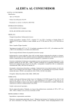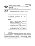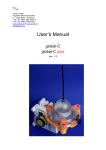
1
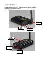
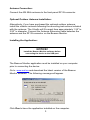
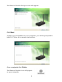
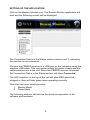
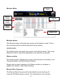
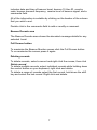
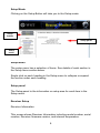
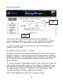
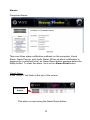
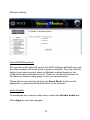
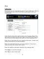
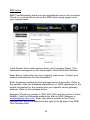
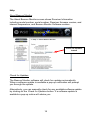
WS Technologies Inc. Beacon Monitor Operator’s Manual for model: FBM200A Version 1.00 Information contained in this manual is subject to change without notice. Please consult the website at www.wst.ca for new Operator’s Manual updates. Complying with all applicable copyright laws is the responsibility of the user. Without limiting the rights under copyright, no part of this document may be reproduced, stored in a retrieval system, or transmitted in any form or by any means including but not limited to, electronic, mechanical, photocopying, recording, or otherwise, or for any purpose, without the written permission of WS Technologies Inc. (WST). WST may have patents, patent applications, trademarks, copyrights, or other intellectual property rights covering subject matter in this document. Except as expressly provided in any written license agreement from WST, the furnishing of this document does not give you any license to these patents, trademarks, copyrights, or other intellectual property. The purchaser shall not in any event be entitled to, and WST shall not be liable for indirect, special, incidental or consequential damages of any nature including, without limitation, business interruption costs, loss of profit or revenue, loss of data, promotional or manufacturing expenses, overhead, injury to reputation or loss of customers, even if WST has been advised of the possibility of such damages. In any event, purchaser's recovery from WST for any claim shall not exceed purchaser's purchase price for the product giving rise to such claim irrespective of the nature of the claim, whether in contract, tort, warranty, or otherwise. WST shall not be liable for and purchaser shall indemnify, defend and hold WST its agents, distributors, dealers, successors and assigns harmless from any and all claims, damages or losses, including injury or death, arising from or relating to the use or failure of the products. Copyright © WS Technologies Inc. All rights reserved. Printed in Canada June 2012 ii CONTENTS INTRODUCTION ................................................................................................. 1 UNPACKING ....................................................................................................... 1 BEACON MONITOR ........................................................................................... 2 Antenna Connection: ....................................................................................... 3 Optional Outdoor Antenna Installation: ............................................................ 3 Installing the Application: ................................................................................. 3 SETTING UP THE APPLICATION ...................................................................... 5 Monitor Mode: .................................................................................................. 6 Monitor button.............................................................................................. 6 Setup button ................................................................................................ 6 Status section .............................................................................................. 6 Beacon Burst log area ................................................................................. 6 Beacon Decode area ................................................................................... 7 Full Screen button ....................................................................................... 7 Deleting records .......................................................................................... 7 Setup Mode: .................................................................................................... 8 Setup Menu ................................................................................................. 8 Setup panel ................................................................................................. 8 Receiver Setup ............................................................................................ 8 Receiver Information................................................................................ 8 Receiver Sensitivity ................................................................................. 9 Alarms ....................................................................................................... 10 Computer Alarms ................................................................................... 10 Visual Alarm .......................................................................................... 10 Alarm Pop-up......................................................................................... 11 Audio Alarm ........................................................................................... 11 Receiver Alarms .................................................................................... 12 Audio/LED/Relay Alarm ......................................................................... 12 Audio Disable ........................................................................................ 12 Alerts ......................................................................................................... 13 E-Mail Alerts .......................................................................................... 13 SMS Alerts............................................................................................. 14 Help ........................................................................................................... 16 About Beacon Monitor ........................................................................... 16 Check for Updates ................................................................................. 16 FREQUENTLY ASKED QUESTIONS ............................................................... 18 SPECIFICATIONS ............................................................................................. 19 REGULATORY INFORMATION ........................................................................ 20 DECLARATION OF CONFORMITY .................................................................. 21 WARRANTY INFORMATION ............................................................................ 22 CALIBRATION................................................................................................... 22 RETURNS ......................................................................................................... 22 MISSION CONTROL CENTER (MCC) CONTACT INFORMATION ................. 23 NOTES .............................................................................................................. 24 iii iv INTRODUCTION Thank you for choosing the FBM200 Beacon Monitor. This Operator’s Manual describes the installation and operation of the Beacon Monitor. UNPACKING Lift up on the inner fold on the right side of the Beacon Monitor box and remove the Beacon Monitor from the underside. The accessories are in the box on the right. Be sure to keep the accessories box for handy storage of the Beacon Monitor Operator’s Manual and accessories when not in use. Please verify the contents of your package. It should contain: Beacon Monitor Operator’s Manual Antenna USB Cable 10’ (3m) Optional items include: Outdoor Antenna Antenna Extension cable 25’ (7.6m) 50’ (15m) 75’ (23m) 100’ (30m) Antenna mounting hardware Certificate of Calibration (optional) NOTICE! Install the Beacon Monitor software before connecting the device to the USB port. 1 BEACON MONITOR Please read this Operator’s Manual to become familiar with the operation of the Beacon Monitor. Antenna Reset button LED Indicator Relay contacts button USB Interface 2 Mounting Flange (4) button Antenna Connection: Connect the 406 MHz antenna to the front panel RF IN connector. Optional Outdoor Antenna Installation: Alternatively, if you have purchased the optional outdoor antenna, install the outdoor antenna following the mounting instructions included with the antenna. The U-bolts will fit a mast from approximately 1.25” to 2.50” in diameter. Connect the Antenna Extension cable between the antenna and the RF IN connector on the Beacon Monitor. Installing the Application: NOTICE! Install the Beacon Monitor software before connecting the device to the USB port. The Beacon Monitor application must be installed on your computer prior to connecting the device. Go to www.wst.ca and download the latest version of the Beacon Monitor software. The following message will appear. Click Run to have the application installed on the computer. 3 The Beacon Monitor Setup screen will appear. Click Next. TM If Java is not installed on your computer, you will be prompted to install it. Follow all on-screen instructions. Once completed click Finish. The Beacon Monitor icon will appear on your computer. 4 SETTING UP THE APPLICATION Click on the Beacon Monitor icon. The Beacon Monitor application will start and the following screen will be displayed: The Connection Status in the Status section shows a red X, indicating the receiver is not connected. Connect the FBM200 receiver to a USB port on the computer using the supplied USB cable. This connection is both the power supply and the communication link to the unit. When the FBM200 receiver is located, the Connection Status in the Status section will show Connected. The LED Indicator on the top of the unit will glow RED when first plugged in, then will flash green when operating normally. There are two main viewing modes: 1. Monitor Mode 2. Setup Mode The following sections will discuss the setup and operation of the software and hardware. 5 Full Screen button Monitor Mode: Monitor button Beacon burst log area Setup button Status section Beacon burst decode area Monitor button The Monitor button will switch the screen to the Monitor mode. This is the normal mode for monitoring beacon burst activity. Setup button The Setup button will switch the screen to the Setup mode. This mode allows the user to setup the application and receiver as needed. Status section The Status section displays the status of the Receiver Connection, the Computer Status, and the Receiver Status. Single click on each heading in the Status section to collapse or expand the section under each heading. Beacon Burst log area The Beacon Burst log area will automatically record and log all received 406 MHz beacon bursts. The information in this section 6 includes date and time of beacon burst, beacon 15 Hex ID, country code, beacon transmit frequency, receive level of beacon signal, and a comments field. All of the information is sortable by clicking on the header of the column that you wish to sort. Double click in the comments field to add or modify a comment. Beacon Decode area The Beacon Decode area shows the decoded message details for any selected burst. Full Screen button To maximize the Beacon Monitor screen click the Full Screen button. To un-maximize the screen press it again. Deleting records To delete records, select a record and right click the mouse, then click Delete record. To delete multiple records, select individual records while holding down the control button on your keyboard, right click and delete. To delete a range of records select the first record, hold down the shift key and select the last record. Right click and delete. 7 Setup Mode: Clicking on the Setup Button will take you to the Setup mode. Setup button Setup panel Setup menu Setup Menu The setup menu has a selection of items. See details of each section in the Setup Items section below. Single click on each heading in the Setup menu to collapse or expand the section under each heading. Setup panel The Setup panel is the information or setup area for each item in the Setup menu. Receiver Setup Receiver Information This screen shows Receiver Information including model number, serial number, Receiver firmware version, and internal temperature. 8 Receiver Sensitivity Slider bars button Apply button The receiver sensitivity can be adjusted for each application. To receive beacon bursts from far away, set the sensitivity to the highest level of -125 dBm. This setting will receive bursts from near also. To receive only the beacons that are near, set the sensitivity to the lowest level of -55 dBm. The default sensitivity level is -115 dBm. The Beacon Monitor has sophisticated algorithms for preventing false triggering. However, burst reception may be hindered when operating the Beacon Monitor in an electrically noisy environment. You may need to remove the source of interference or reduce the sensitivity of the Beacon Monitor. To monitor the ratio of interference events versus valid burst events, go to the Receiver Information screen in Setup Mode. The Burst Counter will show the number of invalid bursts, the number of valid bursts, and the elapsed time in minutes. The Burst Counter numbers are reset each time the Beacon Monitor application is started. Click on the Apply button whenever a change is made. 9 Alarms Computer Alarms There are three alarm notification methods on the computer; Visual Alarm, Alarm Pop-up, and Audio Alarm. When an alarm notification is triggered by a received burst, an Alarm Reset button appears below the Setup button. To clear the alarm, click on the Alarm Reset button. Visual Alarm A red “ALERT” will flash at the top of the screen. Alarm Reset button This alarm is reset using the Alarm Reset button. 10 Alarm Pop-up A pop-up notification will appear in front of any application running on the computer. The Pop-up notification is closed by clicking on the X. Audio Alarm An Audio Alarm will sound through the computer audio system. This alarm is reset using the Alarm Reset button. All 406 MHz beacon bursts are encoded as either: 1. Normal Mode (Live Burst) 2. Self Test mode 3. Test Protocol The user has the option to set each alarm notification method based on the mode of the received beacon burst. It is advised to always be alerted when a Normal Mode (Live Burst) is detected so that the user can take action and notify the authorities of a potential false alert. NOTICE! All Normal Mode bursts have the potential of being received by the satellites causing a false alert. If you are confident that a Normal Mode burst is definitely a false alert and has sufficient power to be received by the satellites, then contact your local Mission Control Center (MCC). Refer to the MCC list on page 23 of this Manual. Check or un-check the boxes on the Computer Alarms setup page to suit your requirements. Click Apply to save the changes. Note that all beacon bursts, regardless of burst mode, will be recorded and logged. The user can delete unwanted records. 11 Receiver Alarms Audio/LED/Relay Alarm The receiver audio alert will sound, the LED Indicator will flash red, and the relay contacts will close when a burst is received. The user has the option to set each receiver alarm notification method based on the mode of the received beacon burst. Check or un-check the boxes on the Receiver Alarms setup page to suit your requirements. These alarms are reset by clicking the Alarm Reset button on the application or pressing the Reset button on the receiver. Audio Disable To deactivate the receiver audio alarm, check the Disable Audio box. Click Apply to save the changes. 12 Alerts E-Mail Alerts Email alerts can be automatically sent to 2 email addresses. Check or un-check the boxes on the E-mail Alerts setup page to suit your requirements. In the Sender Information section enter your Company Name. This information will appear on the email report. Enter the Email Address. This will be the email address the email will show originating from. Enter Server Information for your outgoing mail server. Contact your network administrator for this information. Enter the email addresses for up to two recipients. If only one is required ensure the second field is blank. Enter any addition information desired in the message field. Click Apply to save the changes. Click Test to send a test email. 13 SMS Alerts SMS Text Messaging alerts can be automatically sent to two numbers. Check or un-check the boxes on the SMS Alerts setup page to suit your requirements. In the Sender Information section enter your Company Name. This information will appear on the email report. Enter the Email Address. Enter Server Information for your outgoing mail server. Contact your network administrator for this information. Enter the phone number and the gateway server information. Refer to the website: http://en.wikipedia.org/wiki/List_of_SMS_gateways for the format information for the number and your specific carrier gateway address. Refer to the example below: Example: My phone number is (250) 555-1234 and the carrier is Telus Mobility. From the Wikipedia website the Mail-to-SMS Gateway is [email protected]. Enter your phone number in the Phone Number field. Enter the address to the right of the @ sign in the SMS Text Gateway field. 14 Enter any addition information desired in the Message field. Click Apply to save the changes. Click Test to send a SMS message. NOTE: You are responsible for any charges incurred relating to SMS messages. 15 Help About Beacon Monitor The About Beacon Monitor screen shows Receiver Information including model number, serial number, Receiver firmware version, and internal temperature, and Beacon Monitor Software revision. Check for Updates button Check for Updates The Beacon Monitor software will check for updates automatically. When a software update is available a pop-up notification will prompt you through the update. Alternatively, you can manually check for any available software update by clicking on the Check for Updates button. If a software update is available a pop-up notice will advise you. 16 RECEIVING BURSTS Once your system is setup you should always verify reception by transmitting a self test burst from a 406 MHz beacon. All bursts that are received are logged and recorded. When a burst is a Normal Mode (Live Burst) the entire line item will be highlighted in red (see Index item #7 below). If another Normal Mode burst is received it will be highlighted in red and the previous burst highlight will change to pink. Visual Alarm Normal Mode (Live Burst) reception Once the user clicks on the burst, the pink or red highlight disappears and the 15 HEX ID will remain in red. 17 FREQUENTLY ASKED QUESTIONS Q: How do I manually check for software updates? A: Go to Setup > About Beacon Tester. Click on the Check for Updates button. Q: Do I need internet access to run Beacon Monitor? A: Internet access is required to download and install the Beacon Monitor application; for the program to determine if software updates are available; and to send Email or SMS messaging notifications. Q: Why does Java need to be installed on my machine? A: The Beacon Monitor application is written in Java programming language. The application will not function unless Java is installed. Q: Why does the temperature of the FBM200 read higher than the temperature in the room? A: The temperature reading shows the temperature of the receiver module inside the Beacon Monitor. It is normal for this temperature to be about 10ºC above room temperature. Q: Can I mount the FBM200 outdoors? A: No. The FBM200 is designed for indoor installation. An optional outdoor antenna is available. 18 SPECIFICATIONS BEACON MONITOR FBM200A SPECIFICATIONS SPECIFICATIONS 406 MHz Receiver Sensitivity Out of Band Rejection (<400 MHz, >413 MHz) Harmonic Image Rejection 406 MHz Input Frequency 406 MHz RF Input VSWR 406 Input Impedance 406 Input Connector Receiver power requirements (from USB port) Operating Temperature Range Storage Temperature Range -125 dBm >145 dB >95 dB 406.0 – 406.1 MHz 1.20:1 50Ω SMA-female RP +5V @ <500 mA -40°C to +85°C -55°C to +85°C 108 x 63 x 26 mm 4.3 x 2.5 x 1.0 inches 0.230 kg 0.5 lbs Dimensions: Weight: INCLUDED USB Cable – (3 m length) AC to USB Adapter Ethernet cable (3 m length) Molded 406 MHz Monopole Antenna Outdoor 406 MHz Antenna GPS Active Antenna (5 m cable length) Certificate of Calibration Operator’s Manual User Interface Software O = optional O O FEATURES Receive all Cospas-Sarsat Frequency channels Decode all Cospas-Sarsat Protocols Measure 406 MHz Frequency Measure 406 MHz Receive Power Adjustable Receiver Sensitivity USB Interface Ethernet Interface GPS Receiver GPS Antenna GIS Mapping Audio and LED Alarms Alarm Output – relay contacts 19 REGULATORY INFORMATION CANADA This Class B digital apparatus complies with Canadian ICES-003. USA Note: This equipment has been tested and found to comply with the limits for a Class B digital device, pursuant to part 15 of the FCC Rules. These limits are designed to provide reasonable protection against harmful interference in a residential installation. This equipment generates, uses and can radiate radio frequency energy and, if not installed and used in accordance with the instructions, may cause harmful interference to radio communications. However, there is no guarantee that interference will not occur in a particular installation. If this equipment does cause harmful interference to radio or television reception, which can be determined by turning the equipment off and on, the user is encouraged to try to correct the interference by one or more of the following measures: Reorient or relocate the receiving antenna. Increase the separation between the equipment and receiver. Connect the equipment into an outlet on a circuit different from that to which the receiver is connected. Consult the dealer or an experienced radio/TV technician for help. This equipment complies with Part 15 of the FCC Rules. Operation is subject to the following two conditions: 1. This equipment may not cause harmful interference. 2. This equipment must accept any interference that may cause undesired operation. 20 EUROPEAN UNION DECLARATION OF CONFORMITY Supplier Name: WS Technologies Inc. Supplier Address: #2 – 215 Neave Road Kelowna, B.C. Canada V1V 2L9 Declares under our sole responsibility that the following product Product Name: 406 Beacon Monitor Model FBM200 Conforms to the following normative European and International Standards Normative: Standards: EN 301 489-1 V1.9.2 (2011-09) EN 55022:2006 EN 61000-4-2:2008 EN 61000-4-3:2008 EN 61000-4-4:2004 EN 61000-4-5:2005 EN 61000-4-6:2008 EN 61000-4-11:2004 Following the provisions of the normative European Council Directive 2004/108/EC EMC Directive. Product conformance to cited product specifications is based on sample (type) testing, evaluation or assessment at Celltech Labs, Inc. located in Kelowna, British Columbia, Canada. Supplementary Information: This product was tested and complies with all the requirements for the CE Mark. W.A.Street President WS Technologies Inc. #2 – 215 Neave Road Kelowna, BC Canada V1V 2L9 Phone: (250) 765-7583 FAX: (250) 765-1652 21 WARRANTY INFORMATION WS Technologies Inc. (WST) warrants the products manufactured by WST to be free from defects in material and workmanship for one year from the date of shipment. Liability of WST under the foregoing warranty is limited to the replacement or repair, at the option of WST, of any products which show defective workmanship or materials within one year from the date of shipment, which replacement shall be made FOB WST's facility in Kelowna, BC, CANADA, upon proof satisfactory to WST of the defect claimed. Except for the foregoing warranty, WST makes no other warranty, express or implied, as to the merchantability or fitness for a particular purpose of products shipped or the performance thereof, and does not make any warranty to the purchaser's customers or agents. CALIBRATION The Calibration of the FBM200 Beacon Monitor is optional. If required, the calibration date appears on the Calibration Certificate supplied with the Beacon Monitor and the Cal Due date appears on the sideof the Beacon Monitor housing. Before returning a unit for calibration, email [email protected] to obtain an RMA (Return Materials Authorization) number and shipping instructions. Once calibrated a new Cal Due date label will be placed on the unit and a new Calibration Certificate will be issued. RETURNS An RMA (Return Materials Authorization) number must be obtained by emailing [email protected] . If the unit being returned is not covered under warranty, a minimum repair charge will apply. If damage is severe or the products have been tampered with, there may be additional charges. 22 MISSION CONTROL CENTER (MCC) CONTACT INFORMATION In the event that you believe a Normal Mode (Live Burst) has been transmitted with sufficient power to cause a false alert, the nearest Mission Control Centre (MCC) should be contacted. Please refer to the following list for the MCC in your country. Country/Region Algeria Argentina Australia Brazil Canada Chile China Chinese Taipei France Greece Hong Kong, China India Indonesia Italy Japan Korea (Republic of) Nigeria Norway Pakistan Peru Russian Federation Saudi Arabia Singapore South Africa Spain Thailand Turkey United Arab Emirates United Kingdom United Kingdom (alt) United States Vietnam E-mail [email protected] [email protected] [email protected] [email protected] [email protected] [email protected] [email protected] [email protected] [email protected] [email protected] [email protected] [email protected] [email protected] [email protected] [email protected] [email protected] [email protected] [email protected] [email protected] [email protected] [email protected] [email protected] [email protected] [email protected] [email protected] [email protected] [email protected] [email protected] [email protected] [email protected] [email protected] 23 Phone (213.2) 1491647 (54.11) 44802486 (61.2) 62306820 (55.61) 33652964 (1.613) 9657265 (56.2) 9764042 (86.10) 65293298 (886.2) 87703661 (33.5) 61254382 (30.210) 4191395 (852) 22337999 (91.80) 28094546 (62.21) 5501449 (39.080) 5341571 (81.3) 35916106 (82.32) 8352594 (234) 94134341 (47) 75559000 (92.21) 34690793 (51.1) 4202020 (7.495) 6261215 (966.2) 6150170 (65) 65425024 (27.21) 5529752 (34.928) 727104 (66.2) 2860506 (90.312) 2313374 (971.2) 4056144 (44.1309) 616204 (44.1309) 678304 (1.301) 8174576 (84.31) 3822181 Fax (213.2) 1491648 (54.11) 44802486 (61.2) 62306868 (55.61) 33652964 (1.613) 9657494 (56.2) 9764043 (86.10) 65293296 (886.2) 25450234 (33.5) 61274878 (30.210) 4082870 (852) 25417714 (91.80) 28371857 (62.21) 5501513 (39.080) 5342145 (81.3) 35916107 (82.32) 8352895 (234) 94131749 (47) 75524200 (92.21) 34690797 (51.1) 4291547 (7.495) 6269375 (966.2) 6150171 (65) 65422548 (27.21) 5513760 (34.928) 727107 (66.2) 2873186 (90.312) 2312902 (971.2) 4496844 (44.1309) 678309 (44.1309) 678309 (1.301) 8174568 (84.31) 3842979 NOTES Enter important data here for future reference. Product data FBM200A serial number: _________________ Date Purchased: _________________ Email data Outgoing Mail Server: _________________ Outgoing Mail Server Port: _________________ SMS data SMS Mail Server: SMS Mail Sever Port: Text Number: SMS Text Gateway: _________________ _________________ _________________ _________________ Contacts Supervisor Contact: Phone Number: _________________ _________________ MCC Contact Name: Phone Number: Email Address: _________________ _________________ _________________ 24