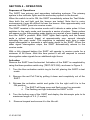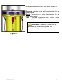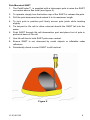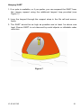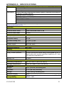
1
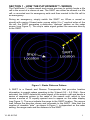
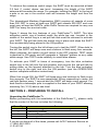
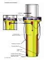
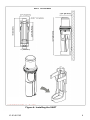
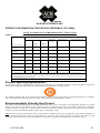
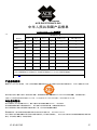
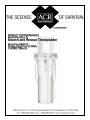
About Cobham Life Support, ACR Products
Cobham Life Support, ACR Products www.acrelectronics.com,
designs and manufactures a complete line of safety and survival
products including EPIRBs, PLBs, AIS, SARTs, Strobe Lights, Life
Jacket Lights, Search Lights and safety accessories. The quality
systems of this facility have been registered by UL to the ISO
9001:2000 Series Standards. Recognized as the world leader in
safety and survival technologies, ACR has provided safety
equipment to the aviation and marine industries as well as to the
military since 1956.
About Cobham plc
Cobham plc is an international company engaged in the
development, delivery and support of advanced aerospace and
defense systems for land, sea, air and space. The company has
four divisions that collectively specialize in the provision of
components, subsystems and services that keep people safe,
improve communications and enhance the capability of aerospace
and defense platforms.
CAUTION: Before proceeding to install, test or use your new
ACR Electronics‟ product, please read this Product Support Manual
in its entirety.
If you have questions regarding the contents of the manual, please
contact our Technical Service Department at ACR Electronics, Inc.,
Telephone +1 (954) 981-3333. Please be ready to provide the
technician with the page number you wish to discuss. If you have a
question that is not covered in the manual, please visit our website
and access the Frequently Asked Questions (FAQs) section for
further information or call our Technical Service Department. The
website address is www.acrelectronics.com. If in the future you lose
this manual, you may access and print a replacement on the ACR
website.
Y1-03-0170G
ii
Table of Contents
SECTION 1 - HOW THE PATHFINDER™3 WORKS ___________________ 1
SECTION 2 - PREPARING TO INSTALL ___________________________ 2
SECTION 3 - INSTALLATION ___________________________________ 4
SECTION 4 - OPERATION _____________________________________ 7
SECTION 5 - MAINTENANCE _________________________________ 11
APPENDIX A - SPECIFICATIONS _______________________________ 13
APPENDIX B - WARRANTY, USEFUL LIFE POLICY, NOTICES __________ 14
PLEASE READ ALL WARNINGS, CAUTIONS
AND NOTES CAREFULLY
Y1-03-0170G
iii
SECTION 1 - HOW THE PATHFINDER™3 WORKS
The PathFinder™3 helps search and rescue services to quickly locate a life
raft in the event of a rescue at sea. The SART can either be stowed in a life
raft, or mounted next to emergency exits and then carried to the life raft in
an emergency.
During an emergency, simply switch the SART on. When a vessel or
aircraft with marine X-band radar comes within 5 to 7 nautical miles of the
life raft, the SART generates a distinctive “distress” pattern on the radar
screen (see Figure 1). The ship‟s radar signal guides the rescuers directly
to the SART.
Figure 1- Radar Distress Pattern
A SART is a Search and Rescue Transponder that provides location
information to search radars operating in the X-band (9.2 – 9.5 GHz). Once
activated, the SART detects the radar signal of the search craft and sends a
series of response pulses to the radar of the search craft, which in turn
causes a series of 12 equally spaced arcs to appear on the radar display
(see Figure 1). The arcs indicate the range to the SART location. The rescue
craft follows the direction shown and proceeds to the SART. Note that the
number of viewable “dots”, as shown in Figure 1, is dependent on the radar
setting, the range scale and the distance to the SART.
Y1-03-0170G
1
To achieve the maximum useful range, the SART must be mounted at least
3.3 feet (1 meter) above sea level. Increasing the height of the SART
antenna will increase the range. For example, lashing the SART to the top of
a pole or an oar in the survival craft will increase the height and thus the
range.
The International Maritime Organization (IMO) requires all vessels of more
than 300 GRT to carry at least one SART and vessels 500 GRT and over
must carry at least two SARTs, while RoRo Ferries are required to carry one
SART for every four survival crafts.
Figure 2 shows the key features of your PathFinder™3 SART. The blue
activation switch ring is located under the white top cap. Located in the
middle of the switch ring is a red pull tab that must be removed to activate
your SART. The pull tab locks the switch ring in place and stops the SART
from accidentally being placed in the ON position.
Turning the switch ring to the left allows you to test the SART. When held to
the left, the SART will beep once and continue to flash every four seconds.
When released, the switch ring will return to the OFF position. TEST mode
is identical to ON mode and will generate a “distress” pattern on any radar
within range. Use TEST mode carefully to avoid false alarms.
To activate your SART in times of emergency, turn the blue activation
switch ring to the left into the test position and remove the red pull tab by
pulling down on the lanyard attached to the tab. Turn the blue activation
switch ring to the right and into the ON position (see the OPERATION
section complete activation instructions).
When first turned ON, the SART will beep once and continue to flash every
four seconds. The SART is now operational. When responding to radar, the
red light flashes every 1 second and the SART will beep every second. For
best results a telescopic pole is supplied in the base of your SART allowing
mounting 1m (3.3 ft) above sea level.
SECTION 2 - PREPARING TO INSTALL
Unpacking the PathFinder™3
Before proceeding with the installation of the PathFinder™3, please verify
that the content of the box includes the following:
Quantity
1
1
1
1
Item
PathFinder™3 search and rescue transponder
Mounting bracket
Product Support Manual
Warranty card
If you do not have all of the items, please call ACR Technical Service at
+1 (954) 981-3333.
Y1-03-0170G
2
Controls and indicators
Antenna
Pull Tab Lock
Activation
Switch
Ring
Pull Tab
Control and
Battery Housing
Hanging Lanyard
Lanyard Spool
Telescopic
Pole
Rotate bottom cap to
release lanyard and
telescopic pole
Figure 2
Y1-03-0170G
3
Vessel name
The SART label has a space where the vessel name is marked (see Figure
3). This can be done as follows.
With an indelible pen, write the vessel name directly onto the SART. Note,
however, that some indelible inks will fade when exposed to strong
sunlight, so a ultra-violet (UV) resistant pen is recommended.
If the full vessel name will not fit in the space provided, use a recognized
abbreviation or the vessel's call sign instead.
Name/Vessel Registration
Nom/Enregistrement De Navire
Vessel Name Here
Figure 3
SECTION 3 - INSTALLATION
Life raft stowage
The SART can either be stowed in a life raft or lifeboat or it can be installed
next to an emergency exit for carriage to the life raft in an emergency.
For life raft stowage the SART should be positioned for easy access in an
emergency. If the SART is hidden from view then labels should be used to
show its position. For inflatable life rafts the mounting bracket should be
discarded to avoid the risk of damaging the life raft.
CAUTION: Do not:
Tie lanyard to vessel
Cover or obscure the SART
Apply paint to SART
Vessel Mounting
To deploy the PathFinder™3 on board a distressed vessel, rather than a life
raft, hang SART near vertical as high as possible, with a clear view of the
horizon. The SART must not be obscured by metal bulkheads etc.
Site selection
The SART should be mounted inside the vessel, next to an emergency exit.
Some ships require 2 SARTs, one by a port exit and one by a starboard
exit. Mount each SART as follows:
Mount in plain view, at a convenient height, so that all crew can easily
remove the SART.
Position at least 1 meter from the ship‟s compass.
Y1-03-0170G
4
CAUTION: Keep this SART at least 3 feet (1 meter) away from all
magnetic sources, stereo speakers and compass installations.
Installation
The SART mounting bracket should be bolted to a bulkhead using four (4)
suitable M6 (1/4") bolts. Mounting hardware for the bracket is not included.
Hardware required depends on the bulkhead material and its thickness.
Bracket mounting holes and SART mounting details are shown in figure 4.
To install the PathFinder™3:
Remove SART from its packaging and check for shipping damage.
Perform the SART test (see Maintenance section for the procedure).
Select a position for SART Mounting allowing sufficient space for the
assembly.
Drill holes to dimensions shown on Figure 4.
Place bracket in position and secure to bulkhead as follows:
Remove the SART from the bracket.
Position bracket at the correct position for maximum visibility
Mark position of bracket fixing holes.
Drill holes to suit mounting fixtures.
Secure bracket to bulkhead.
Mount SART on the bracket (see figure 4).
Secure SART with Velcro strap.
Y1-03-0170G
5
NOT TO SCALE
Figure 4: Installing the SART
Y1-03-0170G
6
SECTION 4 - OPERATION
Sequence of Operations
The SART has primary and secondary indicating systems: The primary
system is the indicator lights and the secondary system is the buzzer.
When the switch is set to ON, the SART immediately enters the Test Mode.
Here both the red light and the buzzer are tested. Note that in noisy
environments it may be difficult to hear the buzzer. After approximately one
second, the SART goes into receive mode.
The SART remains in the receive mode until it detects a radar pulse. It then
switches to the reply mode and transmits a series of pulses. These pulses
will appear on the interrogating radar display as a series of arcs leading away
from the SART„s position. Both SART lights flash rapidly and the buzzer
emits a pulsed sound (beep) at approximately one- second intervals
indicating the reply mode. This sequence is repeated each time a radar
signal interrogates or transmits a valid radar signal to the SART. When the
radar signal interrogation stops, the SART automatically returns to the
receive mode.
With a fully charged battery the SART will operate in receive mode for a
minimum of 96 hours. After this time period it will still respond to normal
interrogation radar signals for an additional eight hours.
Activation
Remove the SART from the bracket. Activation of the SART is completed by
using the three-position switch ring (TEST-OFF-ON), as shown in Figure 5.
1. Turn the blue activation switch ring to the left, placing the SART in test
mode
2. Remove the red Pull Tab by pulling it down and completely out of the
SART
3. Release the activation switch and guide it to the right until it is in the
ON position
i. The SART will beep once and flash every four seconds
ii. The flashing red light indicates the SART is ON
4. Turn the bottom cap of the SART and deploy the telescopic pole to its
maximum length of 3 ft. (1 meter).
5.
Remove lanyard and secure it to the life raft.
Y1-03-0170G
7
When activated the SART has three modes of
operation:
Receive - waiting for a valid interrogation by a
radar signal.
Reply - replying to a valid interrogation by a
valid radar signal.
Test - self-test sequence that checks both
indicator lights and the buzzer.
WARNING: The SART must only be
activated in situations of grave and
imminent danger.
Figure 5
Y1-03-0170G
8
Pole Mounted SART
1. The PathFinder™3 is supplied with a telescopic pole to raise the SART
one meter above sea level (see figure 6).
2. To operate, simply turn the bottom cap of the SART to release the pole.
3. Pull the pole downward and extend it to its maximum length.
4. To lock pole in position pull firmly across pole joints while twisting
slightly.
5. Tie lanyard to life raft to allow retrieval should the SART fall into the
water.
6. Push SART through life raft observation port and place foot of pole in
pocket at base of life raft.
7. Use life raft ties to hold SART pole near vertical.
8. Ensure SART is not obscured by metal objects or inflatable radar
reflectors.
9. Periodically check to see if SART is still vertical.
Figure 6
Y1-03-0170G
9
Hanging SART
1. If no pole is available, or if you prefer, you can suspend the SART from
the canopy support using the additional lanyard loop provided (see
Figure 7).
2. Loop the lanyard through the support strap in the life raft and secure
firmly.
3. The SART should be as high as possible and at least 1m above sea
level. Ensure SART is not obscured by metal objects or inflatable radar
reflectors.
Figure 7
Y1-03-0170G
10
SECTION 5 - MAINTENANCE
This chart is a summary of the procedures described below.
Time interval
Every two months
Every year
Maintenance to do
Visual inspection
Battery expiry date check
Pole operation check
Lanyard check
Safety lock check
Confidence check
Functional test
Every-two-months inspection
The SART is a safety device; it must be regularly checked at least every
two months as follows.
1.) Visually inspect the casing for cracks & punctures.
2.) Extend the pole and check that it operates correctly, and then return the
pole to its housing.
3.) Check to ensure the tether lanyard is neatly bundled and firmly secured
to the SART. Ensure the lanyard is NOT tied to any part of the vessel.
4.) Check that the battery expiry label shows sufficient battery life to cover
the next routine voyage.
5.) Ensure the safety lock is in place and the integrity seal is not broken.
Confidence check
Push the switch ring to the left and into the test position and hold it there for
10 seconds. Confirm the SART does either (a) or (b) below, then release
the switch.
a) Beeps once and the red light flashes continuously every 4 seconds (no
Radar within range).
b) Beeps and the red light flashes every 1 second (answering radar).
Multiple SART Interrogation Test
If your vessel has two PathFinder™3 SARTs on board they may be used to
test each other. This test requires that each SART is held independently, 5
meters away from one another. Turn and hold one SART into the TEST
position. It will beep once and the red light flashes continuously every 4
nd
st
seconds. Next place the 2 SART into the test mode. Confirm that the 1
nd
SART beeps once every time the 2 SART is turned into the test mode.
Repeat this sequence to test the 2
Y1-03-0170G
nd
SART.
11
Functional Test
Perform this test at least once a year.
Get someone to watch the radar screen, while you take the SART to the
ship‟s bow or other location, at least 150m minimum from the radar antenna
to the SART. Hold the switch in its TEST position for no more than 10
seconds. Confirm a "distress" pattern is generated on the radar screen. At
close range the pattern often appears as a series of concentric circles.
Servicing
If the SART fails any of its bimonthly checks, the SART must be returned to
the supplier or an approved service agent for investigation and/or servicing.
If the battery is beyond its expiry date, the SART must be returned to a
Battery Replacement Center for a battery change. The battery is NOT user
serviceable; DO NOT attempt to change it.
If the SART has been used in an emergency or its integrity seal is broken,
then the SART must be returned for a battery change.
Battery Pack Replacement
Regulations require that the battery pack be replaced every 5 years.
NOTE: The battery pack must be replaced if the SART has been used in an
emergency or if the SART has been activated inadvertently (integrity seal
broken).
WARNING: The battery pack cannot be recharged; attempts to recharge
the battery pack could result in an explosion or fire.
Replacement of the SART battery pack must be performed by ACR or by an
authorized ACR Battery Replacement Center. The cost of this replacement is
the responsibility of the owner. See the ACR website for contact information
of Battery Replacement Centers.
Transportation
Your SART contains a lithium battery. For shipping and MSDS information,
visit the ACR website at www.acrelectronics.com. You may also call ACR
Technical Service at +1(954) 981-3333.
Y1-03-0170G
12
APPENDIX A - SPECIFICATIONS
Approvals
Approvals
MED: EC Type Examination Certificate Number: QQ-MED-22/08-01
FCC ID: B66ACR-SART-PF-3
Industry Canada TAC No.:1322A-ACRSART3
Standards
Global Maritime Distress and Safety System (GMDSS) according to
Chapter 3 of IMO SOLAS
IMO Resolution A.802(19)
IMO Resolution A.694(17), Relevant parts
ITU-R M.628-3
IEC 61097-1: 2007
IEC 60945: 2002, EMC Clauses
Part 80 of the FCC Rules
NOTE: For all other type approval information, please visit our website at
www.acrelectronics.com
Antenna
Polarization
Horizontal
Azimuth beam width
Omni-directional within 2 dB
Vertical beam width
Transmitter
Frequency
± 12.5°
Response delay
0.5 µs
Forward sweep time
7.5 µs ± 1.0 µs
Return sweep time
0.4 µs ± 0.1 µs
Power output
Receiver
Effective sensitivity
Battery
400 mW EIRP
Receive mode operation
96 hours minimum
Reply mode operation
8 hours continuous while being interrogated by an Xband radar with a pulse repetition frequency of 1 kHz
(at extreme temperatures).
Battery life
Environmental
5 years
Operating temperature
-4°F to +131°F (-20°C to +55°C)
Storage temperature
-22°F to +149°F (-30°C to +65°C)
9.2 GHz to 9.5 GHz
-50 dBm
Physical
Length
18 in (459 mm) excluding pole
Diameter
3.5 in (90 mm) mid body
Weight
1.5lbs (684 g) including pole
Lanyard Length
Electromagnetic
compatibility
10 m
Meets the applicable requirements of (BS) EN
60945: 1997
Y1-03-0170G
13
APPENDIX B - WARRANTY, USEFUL LIFE POLICY,
NOTICES
Limited Warranty
This product is warranted against factory defects in material and workmanship for a
period of 1 (one) year* from date of purchase or receipt as a gift. During the
warranty period ACR Electronics, Inc. will repair or, at its option, replace the unit at
no cost to you for labor, materials and return transportation from ACR. For further
assistance, please contact our Technical Service Department at ACR Electronics,
Inc., 5757 Ravenswood Road, Fort Lauderdale, FL 33312-6645. Fax: +1 (954) 9835087, Telephone: +1 (954) 981-3333, Email: [email protected],.
This warranty does not apply if the product has been damaged by accident or
misuse, or as a result of service or modification performed by an unauthorized
factory. Except as otherwise expressly stated in the previous paragraph, THE
COMPANY MAKES NO REPRESENTATION OR WARRANTY OF ANY KIND,
EXPRESS OR IMPLIED, AS TO MERCHANTABILITY, FITNESS FOR A
PARTICULAR PURPOSE, OR ANY OTHER MATTER WITH RESPECT TO THIS
PRODUCT. The Company shall not be liable for consequential or special damages.
To place the warranty in effect, register online at www.acrelectronics.com or return
the attached card within 10 days.
*Five years for the following products: EPIRB, PLB, S-VDR, SSAS.
Useful Life Policy
The typical service life of a properly maintained Product is limited to 12 years from
date of manufacture. Products that are 12 years and 1 month or older from date of
manufacture will not be serviced by ACR or our Battery Replacement Centers. A
Product that is 12 or less years old from date of manufacture will be serviced as
long as the unit appears fit to be placed back into its final operational cycle. Service
includes the replacement of those items that must be replaced at service intervals
and the verification that the device appears to be in good mechanical and electrical
working condition by an ACR authorized service technician.
Notices
ACR Electronics diligently works to provide a high quality Product Support Manual,
however, despite best efforts, information is subject to change without notice, and
omissions and inaccuracies are possible. ACR cannot accept liability for manual
contents. To ensure that you have the most recent version of the Product Support
Manual, please visit the ACR website at www.acrelectronics.com.
©2008 by ACR Electronics, Inc., part of Cobham plc. All rights reserved.
Reproduction in whole or in part is permitted only with permission of ACR
Electronics, Inc. Ongoing product improvements may change product specifications
without notice.
Ongoing product improvements may change product specifications without notice.
Trademarks or registered trademarks are the property of their respective owners.
Y1-03-0170G
14
EC DECLARATION OF CONFORMITY
ACR Electronics hereby declares that the following product is in conformity with Council Directive 96/98/EC
of 20 December 1996 on Marine Equipment (MED) last amended by Commission Directive 2008/67/EC of
30 June 2008, and has been type examined as described in this Declaration. In accordance with the
Directive, the product will be marked with the MED Mark of Conformity as follows:
0735
yy
yy = Last two digits of the year in which the mark is affixed
Product:
9 GHz Search and Rescue Transponder (SART), MED Item A.1/4.18
Trade Names: ACR PathFinder™3 SART, ACR TelluSART™ Mk 3 SART
Model: SART-3
Notified Bodies:
QinetiQ, Notified Body No. 0191
Cody Technology Park, Ively Road, Farnborough
Hampshire, GU14 0LX, United Kingdom
EC Type Examination (Module B) Certificate No.: QQ-MED-22/08-01R
Bundesamt für Seeschifffahrt und Hydrographie (BSH), Notified Body No. 0735
Bernhard-Nocht-Str. 78, 20359 Hamburg, Germany
EC Quality System (Module D) Certificate No.: BSH/4613/05102/1251/09
Regulations and
Standards:
IMO Resolution A.694(17)
IMO Resolution A.802(19)
IEC 61097-1 (2007-06)
IEC 60945 (2002-08)
Manufacturer:
ACR Electronics Inc.
5757 Ravenswood Road
Fort Lauderdale, FL 33312
USA
ACR Electronics Inc. (European Office)
1 Rose Cottages, Pitmore Lane,
Sway, Lymington, Hampshire SO41 6BX
UK
European
Representative:
Signed on behalf of ACR Electronics Inc.
Signed:
Name:
Title:
Document SART-3-003
Kerry Greer
Date:
Executive Director Research & Development
December 18, 2009
This Declaration complies with ISO/IEC 17050-1:2004
ACR Electronics, Inc. is registered by UL to ISO 9001:2000
Y1-03-0170G
15
ACR ELECTRONICS INC.
PRODUCT INFORMATION FOR PEOPLE’S REPUBLIC OF CHINA
NOTE TO USERS OF PATHFINDER3 SART, TELLUSART
Table 1
Toxic or Hazardous Substances or Elements
Hexavalent
Chromium
(Cr6+)
Polybrominated
Biphenyls (PBB)
Polybrominated Diphenyl
Ethers (PBDE)
Lead (Pb)
Mercury
(Hg)
Cadmium
(Cd)
Printed circuit
assembly
X
O
O
O
O
O
Battery pack
assembly
X
O
O
O
O
O
Antenna Assembly
X
O
O
O
O
O
Component Name
O: Indicates that the toxic or hazardous substance contained in all of the homogeneous materials for this component is below the limit
requirement in SJ/T11363–2006
X: Indicates that the toxic or hazardous substance contained in at least one of the homogeneous materials used for this component is above
the limit requirement in SJ/T11363–2006
Assemblies include population of components, solder and interconnects.
Product Marking Explanations
In accordance with the requirements specified in SJ/T11364–2006, all ACR EIPs sold in the People’s Republic of China are
marked with a pollution control marking. The following marking applies to ACR products.
This marking indicates that some homogeneous substance within the EIP contains toxic or hazardous substances or elements
above the requirements listed in SJ/T11363–2006. These substances are identified in Table 1.
Environmentally Friendly Use Period
The number in the marking, shown as 20 in the illustration above, refers to the EIP’s Environmentally Friendly Use Period
(EFUP). The EFUP is the number of years from the date of manufacture that toxic or hazardous substances or elements
contained in EIPs will not leak or mutate under the normal operating conditions described in the EIP user documentation,
resulting in any environmental pollution, bodily injury, or damage to assets.
Note Except as expressly stated herein and as required under mandatory provisions of regulations of the People’s Republic of
China, ACR Electronics Inc. makes no representation or warranty of any kind, expressed or implied, with respect to the
EFUP and expressly disclaims any representations or warranties, expressed or implied, with respect to the EFUP.
Y1-03-0170G
16
ACR ELECTRONICS INC.
中华人民共和国产品信息
PATHFINDER3, SART用户须知
表
1
有毒有害物质或元素
部件名称
铅 (Pb)
汞 (Hg)
镉 (Cd)
六价铬
(Cr6+)
多溴联苯 (PBB)
多溴二苯醚 (PBDE)
印刷电路板组件
X
O
O
O
O
O
电池组件
X
O
O
O
O
O
天线组件
X
O
O
O
O
O
O: 表示该有毒有害物质在该部件所有均质材料中的含量均在SJ/T11363-2006 标准规定的限量要求以下。
X: 表示该有毒有害物质至少在该部件的某一均质材料中的含量超出SJ/T11363-2006 标准规定的限量要求。
组件包含元器件,焊接材料和连接件
产品标识说明
根据SJ/T11364-2006 的要求,中华人民共和国境内销售的所有ACR 电子信息产品均注明污染控制标识。 ACR 产品使用以下标识。
该标识表示该电子信息产品某一均质材料中有毒、有害物质或元素的含量超出SJ/T11363-2006 规定的限量。 相关物质见表1。
可能由于产品体积或功能等因素而未直接在产品上注明。 但产品仍符合SJ/T11364-2006 的要求,且其标识信息已在本文说明。
环保使用期限
标识中的数字(即上述图例中的“20”)指电子信息产品环保使用期限 (EFUP) 。 电子信息产
品环保使用期限是指在正常使用的条件下,电子信息产品中含有的有毒、有害物质或元素不会
发生外泄或突变并导致对环境造成严重污染或对人身、财产造成严重损害的期限。
注除根据中华人民共和国法规的强制性规定在此作出明示声明的以外, ACR Electronics Inc.
对电子信息产品环保使用期限不作任何形式的陈述或保证(无论是明示或默示),并且不对电子信息产品环保使用期限的任何陈述或
保证(无论是明示或默示)承担任何责任。
Y1-03-0170G
17