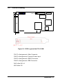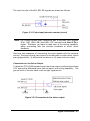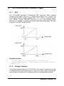
1
PCI-8136M
6-Axis Motion Controller Card
User’s Guide
©Copyright 2000 ADLink Technology Inc.
All Rights Reserved.
Manual Rev. 1.00: Oct 20, 2000
The information in this document is subject to change without prior notice in
order to improve reliability, design and function and does not represent a
commitment on the part of the manufacturer.
In no event will the manufacturer be liable for direct, indirect, special,
incidental, or consequential damages arising out of the use or inability to use
the product or documentation, even if advised of the possibility of such
damages.
This document contains proprietary information protected by copyright. All
rights are reserved. No part of this manual may be reproduced by any
mechanical, electronic, or other means in any form without prior written
permission of the manufacturer.
Trademarks
NuDAQ, PCI-8136,PCI-8136M are registered trademarks of ADLINK
Technology Inc, MS-DOS & Windows 95 are registered trademarks of
Microsoft Corporation., Borland C++ is a registered trademark of Borland
International, Inc. Other product names mentioned herein are used for
identification purposes only and may be trademarks and/or registered
trademarks of their respective companies.
Getting service from ADLINK
Customer Satisfaction is always the most important thing for ADLink Tech
Inc. If you need any help or service, please contact us and get it.
ADLINK Technology Inc.
Web Site
Sales & Service
Technical
Support
TEL
Address
http://www.adlink.com.tw
[email protected]
NuDAQ
[email protected]
NuDAM
[email protected]
NuIPC
[email protected]
NuPRO
[email protected]
Software
[email protected]
+886-2-82265877
FAX
+886-2-82265717
9F, No. 166, Jian Yi Road, Chungho City, Taipei, 235 Taiwan, R.O.C.
Please inform or FAX us of your detailed information for a prompt,
satisfactory and constant service.
Detailed Company Information
Company/Organization
Contact Person
E-mail Address
Address
Country
TEL
Web Site
FAX
Questions
Product Model
Environment to Use
Challenge Description
Suggestions to ADLINK
OS
Computer Brand
M/B:
CPU:
Chipset:
BIOS::
Video Card :
Network Interface Card:
Other:
Table of Contents
Chapter 1 Introduction.........................................................1
1.1
1.2
1.3
Functionality of PCI-8136M .................................................3
Features ............................................................................4
Specifications .....................................................................5
1.3.1
1.3.2
1.3.3
1.3.4
1.3.5
1.4
Applicable Motors: ........................................................................5
Motion .............................................................................................5
Motion Interface I/O Signals........................................................5
General I/Os...................................................................................6
General Specifications.................................................................7
Software Supporting ...........................................................8
1.4.1
Programming Library....................................................................8
Chapter 2 Installation...........................................................9
2.1
2.2
2.3
What You Have ................................................................ 10
Outline Drawing................................................................ 11
Hardware Installation ........................................................ 12
2.3.1
2.3.2
2.3.3
2.3.4
2.4
2.5
2.6
2.7
2.8
Hardware configuration............................................................. 12
PCI slot selection....................................................................... 12
Installation Procedures.............................................................. 12
Trouble shooting:....................................................................... 12
Software Installation.......................................................... 13
CN1 PIN ASSIGNMENTS: MAIN CONNECTOR................. 14
CN2 PIN ASSIGNMENTS: EXTERNAL POWER INPUT ..... 15
CN3 PIN ASSIGNMENTS: DB25 CONNECTOR................. 16
CN4 PIN ASSIGNMENTS: DB9 CONNECTOR................... 16
Chapter 3 Signal Connection...........................................17
3.1
3.2
3.3
3.4
3.5
3.6
3.7
3.8
3.9
3.10
3.11
Pulse output signals OUT and DIR..................................... 18
Voltage output signals DAC............................................... 20
Encoder feedback signals EA, EB and EZ .......................... 22
Analog Input ..................................................................... 25
Origin signal ORG............................................................. 27
End-Limit signals PEL and MEL......................................... 28
Emergency stop signal ESTOP.......................................... 29
Servo on signal SVON ...................................................... 30
General purpose output P-RDY ......................................... 31
VCC Pin ........................................................................... 31
Open Loop and Closed Loop Connection ........................... 32
Table of contents • i
Chapter 4 Operation Theorem .........................................33
4.1
AD Conversion and Preloaded Trigger ............................... 35
4.1.1
4.1.2
ADC.............................................................................................. 35
Voltage Compare ....................................................................... 35
4.2
DA Conversion ................................................................. 36
4.3
Local DIO ......................................................................... 37
4.2.1
4.3.1
4.3.2
4.4
Pulse Input.................................................................................. 38
Position Counter Value Capture (Latch)................................ 39
Position Compare....................................................................... 40
Pulse Output .................................................................... 41
Remote Serial IO .............................................................. 43
Introduction to DDA........................................................... 44
Open-loop and close-loop control....................................... 45
4.8.1
4.8.2
4.9
4.10
4.11
4.12
4.13
4.14
4.15
4.16
Digital Input................................................................................. 37
Digital Output.............................................................................. 37
Pulse Input and Position Compare ..................................... 38
4.4.1
4.4.2
4.4.3
4.5
4.6
4.7
4.8
DA Output by Trigger Source................................................... 36
Open-loop control....................................................................... 45
Close-loop control...................................................................... 45
Constant Velocity Motion................................................... 46
Trapezoidal Motion ........................................................... 47
S-Curve Profile Motion ...................................................... 49
2D Interpolation ................................................................ 51
3D Interpolation ................................................................ 54
Home Return Mode........................................................... 55
Motion Parameters Setting ................................................ 56
The Motion IO Interface..................................................... 57
4.16.1
4.16.2
4.16.3
4.16.4
SERVO ON ................................................................................. 57
Limit Switch Signal..................................................................... 57
ORG ............................................................................................. 57
Emergency stop signal (ESTOP)............................................. 57
4.17 Interrupt Control................................................................ 59
Chapter 5 Motion Library ..................................................62
5.1
5.2
5.3
5.4
5.5
5.6
5.7
5.8
5.9
List of Functions ............................................................... 63
Initialization ...................................................................... 65
System Parameters .......................................................... 67
Card Information ............................................................... 69
Digital I/O......................................................................... 70
Remote I/O....................................................................... 72
Analog I/O........................................................................ 74
Pulse I/O.......................................................................... 77
Interrupt Control................................................................ 81
ii • Table of Contents
5.10
5.11
5.12
5.13
5.14
5.15
5.16
5.17
5.18
Close Loop Initialization .................................................... 84
Motion Parameters ........................................................... 85
Motion Status ................................................................... 88
PTP Movement ................................................................. 90
2D Interpolation ................................................................ 92
3D Interpolation ................................................................ 94
Continuous Motion ............................................................ 96
Homing ............................................................................ 97
Motion Function ................................................................ 98
Product Warranty/Service..................................................99
Table of contents • iii
How to Use This Guide
This manual is designed to help you use the PCI-8136M. The manual
describes how to modify various settings on the PCI-8136M card to meet
your requirements. It is divided into five chapters:
•
Chapter 1, "Introduction", gives an overview of the product features,
applications, and specifications.
•
Chapter 2, "Installation", describes how to install the PCI-8136M.
•
Chapter 3, "Signal Connection", describes the connectors' pin
assignment and how to connect the outside signal and devices with
the PCI-8136M.
•
Chapter 4, "Operation Theorem", describes detail operations of the
PCI-8136M.
•
Chapter 5,"Motion Library", describes high-level programming
interface in C/C++ language. It helps programmer to control
PCI-8136M in high-level language style
iv • How to Use This Guide
1
Introduction
The PCI-8136M is a 6 axes motion control card with PCI interface. It supports
two kinds of motor driver, Pulse type and voltage type. It can generate pulse
trains or voltage commands for servo motors or stepping motors. The
PCI-8136M is composed of 6 sets of motion control module. Each control set
has its own pulse generator, encoder counter, analog output, dedicated I/O
and analog input. When one axis is not for motion control, all of the
components in the motion set can be used individually. Therefore, the
PCI-8136M has maximum flexibility on industrial applications.
Figure 1.1 shows the function block diagram of PCI-8136M card. PCI-8136M
uses one motion control ASIC to perform 6 axes motion control. This ASIC
outputs the velocity profile through DDA module from the motion library. It
supports one axis PTP, two axes linear interpolation, two axes circular
interpolation, three axis linear interpolation with linear and S-curve
acceleration/deceleration velocity profiles.
The PCI-8136M can work with Microsoft Windows series without any
real-time OS. The PCI-8136M supports Windows DLL and drivers. Users can
develop their own applications by Visual C++, Visual Basic, C++ Builder or
Delphi. It is very easy to use PCI-8136M's function library because all
functions are not register based. They are very easy for use and friendly to
every modern PC users. It also can work with MS-DOS with Borland C++ 3.1.
Introduction • 1
Servo,Stepping Motors & Drivers
Sensor
System
Bus
PCI-8136M
1
2
3
4
ADC x 6
Pulse Command
B
U
S
DDA x 6
I
F
Encoder Counter x 6
LR
Local Digital I/O 26
IF
PLC x 6
LD
V Command
DAC x 6
Remote IO Master #1
64In/64Out
T
M Remote IO Master #2
64In/64Out
Pulse Signals
Serial IO
Slave #1
64In/64Out
DR
Serial IO
DR
Slave #2
64In/64Out
Figure 1.1 Block Diagram of PCI-8136M
2 • Introduction
5
6
1.1
Functionality of PCI-8136M
The PCI-8136M is composed of 6 sets of motion control module. Each
control set has its own pulse generator, encoder counter, analog output,
dedicated I/O and analog input. When one axis is not for motion control, all of
the components in the motion set can be used individually.
The following table regards the number of motion axes and remaining
available functions.
No. of Motion
Axes
Remain
Functions
0
1
2
3
4
5
6
Analog Input
6
6
6
6
6
6
6
Analog Output
6
(5) 6
(4) 6
(3) 6
(2) 6
(1) 6
(0) 6
Digital Input
19
15/19
12/19
9/19
6/19
3/19
0/19
Digital Output
7
6/7
5/7
4/7
3/7
2/7
1/7
6
5/6
4/6
3/6
2
1
0
6
6
5
4
3
2
1
Pulse Input
(Encode Counter)
Pulse Output
(Pulse Generator)
Note: () means close loop control mode with v command output is set.
For example: If 2 motion axes are used, it remains
• 6 AI
‚ 4 or 6 AO(depends on command type)
ƒ 12 or 19 DI (depends on if motion I/O is active or not)
„ 4 or 7 DO (depends on if servo-on is used nor not)
… 4 or 6 encoder counters( depends on if motion feedback is
connected nor not)
† 4 pulse generators for general use
Introduction • 3
1.2
Features
The PCI-8136M gets the following features:
•
Compact, half size PCB
•
32-bit PCI-bus, plug and play
•
6 channels 16-bit analog output
•
6 channels 12-bit analog input
•
19 channels isolated digital input
•
7 channels open collector digital output
•
Programmable interrupt sources
•
6 differential types 32-bit encoder counters
•
6 differential type pulse generators
•
2 optional remote I/O modules with 128 I/Os
•
One 24-bit programmable timer
•
Software supports maximum up to 4 cards
•
6-axis motion control ability with voltage(closed-loop) & pulse(open
loop) type command output
•
Applicable motor type: Analog & digital servo, stepping & micro
stepping
•
Support Trapezoidal and S-curve velocity profile for every motion
functions
•
One axes PTP control
•
Any 2 axes linear interpolation
•
Any 2 axes circular interpolation
•
Any 3 axes linear interpolation
•
Function library for DOS and Windows 95/98/NT/2000
•
Real Time OS needless
4 • Introduction
1.3
Specifications
1.3.1
Applicable Motors:
•
Stepping motors
•
AC or DC servomotors with pulse train input servo drivers
•
AC or DC servomotors with velocity command (analog) input servo
drivers
1.3.2
Motion
•
Number of controllable axes: selectable 1~6 Axes
•
Motion command output type: selectable Voltage or Pulse
command
•
Max NO. of cards in one system: 4
•
Pulse command output up to 1024KHz
•
Control loop cycle time up to 1.024 ms
•
Analog command output range: ±10V
•
32-bit 2 MHz Up/Down counter for encoder feed back signals (each
axis)
•
32-bit position comparator with interrupt (each axis)
1.3.3
Motion Interface I/O Signals
•
2500 Vrms optically isolated for all Motion Interface IO
•
Incremental encoder signals input pins: EA and EB (each axis)
•
Encoder index signal input: EZ (each axis)
•
Mechanical limit switch signal input pins: ±EL, and ORG (each axis)
•
Servomotor interface I/O pins: SVON (each axis)
•
Emergency stop signal input: ESTOP
Introduction • 5
1.3.4
♦
General I/Os
Analog Input
•
6 differential input channels
•
Input range: Voltage: ±10V
Current: ±20 mA (manually soldering 124ohms resistor)
•
12-bit ADC with 1-bit non-linearity
•
Input impedance : 10 Ohms || 100pF (voltage mode)
12
124Ohms (current mode)
•
♦
Sampling rate: 133 KHz multiplexing
Analog Output
•
6 output channels
•
Output range: bipolar, ±10V
•
16-bit DAC resolution, 14-bit accuracy guaranteed
•
Settling time: 2 µ second
•
Voltage output drive: 5mA max.
♦
Digital Input
•
19 input channels for NPN type sensor
•
Input impedance: 4.7K Ohms
•
Max. Current: 20mA
•
Isolated voltage: 2500V RMS
•
Throughput: 10KHz (0.1ms)
♦
Digital Output
•
7 Output channels
•
Output type : Darlington transistor with open collector type
(ULN2003A)
•
Sink current : 90mA/Ch (typical)
6 • Introduction
150mA/Ch (max.)
500mA/total
•
Isolated voltage 2500V RMS
•
Throughput 10KHz(0.1ms)
♦
Pulse Input (Encoder Counter)
•
6 differential input channels
•
32-bit counter for AB-phase, CW/CCW, Pulse/Direction modes
•
2500V RMS optical isolation
•
Maximum pulse i nput frequency: 2MHz
•
32-bit encoder counter comparison
♦
Pulse Output (Pulse Generator):
•
6 output channels with differential line drivers
•
Pulse command type: CW/CCW, Pulse/Direction, A/B Phase
•
Maximum pulse rate: 500KHz with 1 µ second pulse width
♦
Timer:
•
One 24-bit programmable timer
•
Base clock: 33MHz from PCI bus
1.3.5
General Specifications
♦
Connectors:
♦
100-pin SCSI-type connector
•
DB25 female connector
•
DB9 male connector
♦
Operating Temperature: 0° C ~ 50° C
♦
Storage Temperature: -20° C ~ 80° C
♦
Humidity: 5 ~ 85%, non-condensing
Introduction • 7
♦
Power Consumption:
•
Slot power supply(input): +5V DC ±5%, 900mA max
•
External power supply(input): +24V DC ±5%, 500mA max
•
External power supply(output): +5V DC ±5%, 500mA, max
♦
1.4
Dimension: 164mm(L) X 98.4mm(H)
Software Supporting
1.4.1
Programming Library
The Programming Library enables motion control functionality of PCI-8136M.
It provides versatile function calls for customers who are writing their own
motion control programs. The Motion Library supports MS-DOS Borland
C/C++ with programming library and Windows 95/98/NT/2000 with DLL.
8 • Introduction
2
Installation
This chapter describes how to install the PCI-8136M hardware and software
correctly. Please follow the follow steps.
Section 2.1
Check what you have
Section 2.2
PCB Outline Drawing
Section 2.3
Install the hardware
Section 2.4
Install the software driver
Section 2.5
CN1 Pin Assignments
Section 2.6
CN2 Pin Assignments
Section 2.7
DB25 Connector
Section 2.8
DB9 Connetctor
Installation • 9
2.1
What You Have
In addition to this User's Guide, the package includes the following items:
•
PCI-8136M 6-axis Motion Controller Card
•
DB9 and DB25 Bracket
•
External Power cable for CN2
•
124O, DIP type resistance * 6
•
ADLINK All-in-one Compact Disc
•
PCI-8136M User’s Manual
If any of these items are missing or damaged, contact the dealer from whom
you purchased the product. Save the shipping materials and carton in case
you want to ship or store the product in the future.
10 • Installation
2.2
Outline Drawing
1
CN2
CN3
6
DAC Offset VR
CN4
ADC Offset VR
CN1
Figure 2.2.1 PCB Layout of the PCI-8136M
CN1 Pin Assignments : Main Connector
CN2 Pin Assignments: External Power Input
CN3 Pin Assignments : DB25 Connector
CN4 Pin Assignments : DB9 Connector
DAC offset VR1~6
ADC offset VR
Installation • 11
2.3
Hardware Installation
2.3.1
Hardware configuration
PCI-8136M has plug and play PCI controller on board. The memory usage
(I/O port locations) of the PCI card is assigned by system BIOS. The address
assignment is done on a board-by-board basis for all PCI cards in the system.
2.3.2
PCI slot selection
Your computer will probably have both PCI and ISA slots. Do not force the
PCI card into a PC/AT slot. The PCI-8136M can be used in any PCI slot.
2.3.3
Installation Procedures
1.
Read through this manual, and setup the jumper according to your
application.
2.
Turn off your computer, Turn off all accessories (printer, modem,
monitor, etc.) connected to computer.
3.
Remove the cover from your computer.
4.
Select a 32-bit PCI expansion slot. PCI slots are short than ISA or
EISA slots and are usually white or ivory.
5.
Before handling the PCI-8136M, discharge any static buildup on your
body by touching the metal case of the computer. Hold the edge and
do not touch the components.
6.
Position the board into the PCI slot you selected.
7.
Secure the card in place at the rear panel of the system unit using
screw removed from the slot.
2.3.4
Trouble shooting:
If your system won't boot or if you experience erratic operation with your PCI
board in place, it's likely caused by an interrupt conflict (perhaps because you
incorrectly described the ISA setup). In general, the solution, once you
determine it is not a simple oversight, is to consult the BIOS documentation
that come with your system.
12 • Installation
2.4
Software Installation
Please refer to the ADLINK All-in-one Compact Disc Manual to install it.
Installation • 13
2.5
CN1 PIN ASSIGNMENTS: MAIN CONNECTOR
The CN1 is the major connector for the Motion related I/O, including pulse
output, encoder feedback input, Analog output and interface IO signals.
No.
Name
I/O
1
2
3
4
5
6
7
8
9
10
11
12
13
14
15
16
17
18
19
20
21
22
23
24
25
26
27
28
29
30
31
32
33
34
35
36
37
38
39
40
41
42
43
44
45
46
47
48
49
50
AGND
DAC1
DAC2
DAC3
ACC+5V
COM+
COM+
COM+
ORG1
PEL1
MEL1
SVON1
ORG3
PEL3
MEL3
SVON3
ORG5
PEL5
MEL5
SVON5
EA1+
EA1EB1+
EB1EZ1+
EZ1EA3+
EA3EB3+
EB3EZ3+
EZ3EA5+
EA5EB5+
EB5EZ5+
EZ5OUT1+
OUT1DIR1+
DIR1OUT3+
OUT3DIR3+
DIR3OUT5+
OUT5DIR5+
DIR5-
SG
O
O
O
O
P
P
P
I
I
I
O
I
I
I
O
I
I
I
O
I
I
I
I
I
I
I
I
I
I
I
I
I
I
I
I
I
I
O
O
O
O
O
O
O
O
O
O
O
O
14 • Installation
Function
Analog ground
Analog output, •
Analog output, ‚
Analog output, ƒ
+5V from PC
+24V Input for Digital I/O
+24V Input for Digital I/O
+24V Input for Digital I/O
Origin signal, •
End limit signal (+), •
End limit signal ( -), •
Servo on signal, •
Origin signal, ƒ
End limit signal (+), ƒ
End limit signal ( -), ƒ
Servo on signal, ƒ
Origin signal, …
End limit signal (+),…
End limit signal ( -),…
Servo on signal, …
Encoder A-phase (+), •
Encoder A-phase (-), •
Encoder B-phase (+), •
Encoder B-phase (-), •
Encoder Z-phase (+), •
Encoder Z-phase (-), •
Encoder A-phase (+), ƒ
Encoder A-phase (-),ƒ
Encoder B-phase (+),ƒ
Encoder B-phase (-),ƒ
Encoder Z-phase (+),ƒ
Encoder Z-phase (-),ƒ
Encoder A-phase (+),…
Encoder A-phase (-),…
Encoder B-phase (+),…
Encoder B-phase (-),…
Encoder Z-phase (+),…
Encoder Z-phase (-),…
Pulse signal (+),•
Pulse signal ( -),•
Dir. signal (+),•
Dir. Signal ( -),•
Pulse signal (+), ƒ
Pulse signal ( -),ƒ
Dir. signal (+), ƒ
Dir. signal ( -), ƒ
Pulse signal (+),…
Pulse signal (-),…
Dir. signal (+),…
Dir. Signal ( -),…
No.
Name
I/O
51
52
53
54
55
56
57
58
59
60
61
62
63
64
65
66
67
68
69
70
71
72
73
74
75
76
77
78
79
80
81
82
83
84
85
86
87
88
89
90
91
92
93
94
95
96
97
98
99
100
AGND
DAC4
DAC5
DAC6
COMCOMESTOP
PRDY
ORG2
PEL2
MEL2
SVON2
ORG4
PEL4
MEL4
SVON4
ORG6
PEL6
MEL6
SVON6
EA2+
EA2EB2+
EB2EZ2+
EZ2EA4+
EA4EB4+
EB4EZ4+
EZ4EA6+
EA6EB6+
EB6EZ6+
EZ6OUT2+
OUT2DIR2+
DIR2OUT4+
OUT4DIR4+
DIR4OUT6+
OUT6DIR6+
DIR6-
SG
O
O
O
PG
PG
I
O
I
I
I
O
I
I
I
O
I
I
I
O
I
I
I
I
I
I
I
I
I
I
I
I
I
I
I
I
I
I
O
O
O
O
O
O
O
O
O
O
O
O
Function
Analog ground
Analog output, „
Analog output, …
Analog output, †
+24V Ground
+24V Ground
Emergency stop signal
General-purposed output
Origin signal, ‚
End limit signal (+), ‚
End limit signal ( -), ‚
Servo on signal, ‚
Origin signal, „
End limit signal (+), „
End limit signal ( -), „
Servo on signal, „
Origin signal, †
End limit signal (+),†
End limit signal ( -),†
Servo on signal, †
Encoder A-phase (+), ‚
Encoder A-phase (-), ‚
Encoder B-phase (+), ‚
Encoder B-phase (-), ‚
Encoder Z-phase (+), ‚
Encoder Z-phase (-), ‚
Encoder A-phase (+), „
Encoder A-phase (-), „
Encoder B-phase (+), „
Encoder B-phase (-), „
Encoder Z-phase (+), „
Encoder Z-phase (-), „
Encoder A-phase (+),†
Encoder A-phase (-),†
Encoder B-phase (+),†
Encoder B-phase (-),†
Encoder Z-phase (+),†
Encoder Z-phase (-),†
Pulse signal (+), ‚
Pulse signal ( -), ‚
Dir. Signal (+), ‚
Dir. Signal ( -), ‚
Pulse signal (+),„
Pulse signal ( -),„
Dir. signal (+),„
Dir. signal ( -),„
Pulse signal (+),†
Pulse signal ( -),†
Dir. signal (+),†
Dir. Signal ( -),†
2.6
CN2 PIN ASSIGNMENTS: EXTERNAL POWER INPUT
CN2 Pin No
1
2
Name
EXGND
EX+24V
Description
Grounds of the external power.
External power supply of +24V DC ± 5%
Cable Color
Black
Red
Notes:
1.
CN2 is a plug-in terminal connector with no screw.
2.
Be sure to use the external power supply. The +24V DC is used by
external input/output signal circuit.
3.
Wires for connection to CN2.
Solid wire: ϕ 0.32mm to ϕ 0.65mm (AWG28 to AWG22)
Twisted wire:0.08mm2 to 0.32mm2 (AWG28 to AWG22)
Naked wire length:10mm standard
4.
The EX+24V is shorted inside PCI-8136M with COM+ in CN1 (No.
6,7,8).
5.
The EXGND is shorted inside PCI-8136M with COM- in CN1 (No.
55,56).
Installation • 15
2.7
CN3 PIN ASSIGNMENTS: DB25 CONNECTOR
The signals on CN3 are for Analog input and remote serial IO.
Remote serial IO #2
G2SIOCLK/ (1)
G2SCS0/ (2)
G2S2MD/ (3)
G2M2SD/ (4)
AGND (5)
DAC3 (6)
Analog output
ADC1- (7)
ADC2- (8)
Analog input
ADC3- (9)
ADC4- (10)
ADC5- (11)
ADC6- (12)
AGND (13)
(14) G2SIOCLK
(15) S2SCS0
(16) G2S2MD
(17) G2M2SD
(18) DAC1
(19) DAC2
(20) ADC1+
(21) ADC2+
(22) ADC3+
(23) ADC4+
(24) ADC5+
(25) ADC6+
NC
Note:
1. The DAC1~3 pins are the same with those on CN1
2. The Remote Serial IO #2 is reserved for future functions
2.8
CN4 PIN ASSIGNMENTS: DB9 CONNECTOR
The signals on CN4 are for remote serial IO#1.
G1SIOCLK/ (1)
G1SCS0/ (2)
G1S2MD/ (3)
G1M2SD/ (4)
GND (5)
16 • Installation
(6) G1SIOCLK
(7) S1SCS0
(8) G1S2MD
(9) G1M2SD
3
Signal Connection
The signal connections of all the I/O signals are described in this chapter.
Please refer the contents of this chapter before wiring the cable between the
PCI-8136M and the motor drivers.
This chapter contains the following sections:
Section 3.1
Pulse output signals OUT and DIR
Section 3.2
Voltage output signals DAC
Section 3.3
Encoder feedback signals EA, EB and EZ
Section 3.4
Voltage input signals ADC
Section 3.5
Origin signal ORG
Section 3.6
End-Limit signals PEL and MEL
Section 3.7
Emergency stop signal ESTOP
Section 3.8
Servo on signal SVON
Section 3.9
General purpose output PRDY
Section 3.9
VCC pins
Section 3.10 Open loop and closed loop connections
Signal Connection • 17
3.1
Pulse output signals OUT and DIR
There are 6-axis pulse output signals on PCI-8136M. For every axis, two
pairs of OUT and DIR signals are used to send the pulse train and to indicate
the direction. The OUT and DIR signals can also be programmed as
CW/CCW or AB phase signals pair. In this section, the electronic
characteristics of the OUT and DIR signals are shown. Each signal consists
of a pair of differential signals. For example, the OUT2 is consisted of OUT2+
and OUT2- signals. The following table the ping assignment for pulse output
signal.
CN1 PIN No
39
40
41
42
89
90
91
92
43
44
45
46
83
84
85
86
47
48
49
50
97
98
99
100
Signal Name
OUT1+
OUT1DIR1+
DIR1OUT2+
OUT2DIR2+
DIR2OUT3+
OUT3DIR3+
DIR3OUT4+
OUT4DIR4+
DIR4OUT5+
OUT5DIR5+
DIR5OUT6+
OUT6DIR6+
DIR6-
Description
Pulse Signal (+)
Pulse Signal (-)
Direction Signal (+)
Direction Signal (-)
Pulse Signal (+)
Pulse Signal (-)
Direction Signal (+)
Direction Signal (-)
Pulse Signal (+)
Pulse Signal (-)
Direction Signal (+)
Direction Signal (-)
Pulse Signal (+)
Pulse Signal (-)
Direction Signal (+)
Direction Signal (-)
Pulse Signal (+)
Pulse Signal (-)
Direction Signal (+)
Direction Signal (-)
Pulse Signal (+)
Pulse Signal (-)
Direction Signal (+)
Direction Signal (-)
Axis No.
1
2
3
4
5
6
The output of the OUT or DIR signals are differential line driver type.
Here is the circuit of PCI-8136M pulse output (pulse generator) channels.
18 • Signal Connection
Figure 3.1.1 Pulse output (pulse generator) circuit
If the driver side is open collector mode, please use any one of positive and
negative pins to be a control signal and EXGND as its output ground. Please
take care that the current sink to these pins must not exceed 20mA.
Signal Connection • 19
3.2
Voltage output signals DAC
There are 6 DAC output channels on PCI-8136M. If the closed loop control
mode is set for any one of the 6 axes, its corresponding DAC channel will be
treated as voltage command output. If not, the DAC channel will be treated as
a general purposed analog output channel.
The resolution of DAC is 16-bit, and the output voltage ranged from -10 V to
+10V. To make correct connection, please refer to following figure:
Figure 3.2.1 DAC circuit
The Analog outputs are all single ended with common ground ‘AGND’. The
following table is the pin assignment information for DAC.
CN1 Pin No
Signal Name
Description
2
DAC1
DAC Channel 1
3
DAC2
DAC Channel 2
4
DAC3
DAC Channel 3
52
DAC4
DAC Channel 4
53
DAC5
DAC Channel 5
54
DAC6
DAC Channel 6
1
AGND
Analog Ground
51
AGND
Analog Ground
CN3 Pin No
18
19
6
5
13
20 • Signal Connection
Signal Name
DAC1
DAC2
DAC3
AGND
AGND
Description
DAC Channel 1
DAC Channel 2
DAC Channel 3
Analog Ground
Analog Ground
Notice that the DAC Channel 1~ 3 in CN1 and CN3 are connected inside the
PCI-8136M.
Signal Connection • 21
3.3
Encoder feedback signals EA, EB and EZ
The PCI-8136M provides 6 differential pulse inputs with 2500V rms isolation,
and each pair of EA, EB, and EZ is related to one motion axis. The pulse
mode is software programmable to be AB-phase, CW/CCW, or
Pulse/Direction, and the counter speed goes up to 2 MHz. The following
table is the pin assignments for encoder counters.
CN1 Pin No.
21
22
23
24
25
26
71
72
73
74
75
76
27
28
29
30
31
32
77
78
79
80
81
82
33
34
35
36
37
38
83
84
85
86
87
88
Signal Name
EA1+
EA1EB1+
EB1EZ1+
EZ1EA2+
EA2EB2+
EB2EZ2+
EZ2EA3+
EA3EB3+
EB3EZ3+
EZ3EA4+
EA4EB4+
EB4EZ4+
EZ4EA5+
EA5EB5+
EB5EZ5+
EZ5EA6+
EA6EB6+
EB6EZ6+
EZ6-
22 • Signal Connection
Description
Encoder A-Phase (+)
Encoder A-Phase (-)
Encoder B-Phase (+)
Encoder B-Phase (-)
Encoder Z-Phase (+)
Encoder Z-Phase (-)
Encoder A-Phase (+)
Encoder A-Phase (-)
Encoder B-Phase (+)
Encoder B-Phase (-)
Encoder Z-Phase (+)
Encoder Z-Phase (-)
Encoder A-Phase (+)
Encoder A-Phase (-)
Encoder B-Phase (+)
Encoder B-Phase (-)
Encoder Z-Phase (+)
Encoder Z-Phase (-)
Encoder A-Phase (+)
Encoder A-Phase (-)
Encoder B-Phase (+)
Encoder B-Phase (-)
Encoder Z-Phase (+)
Encoder Z-Phase (-)
Encoder A-Phase (+)
Encoder A-Phase (-)
Encoder B-Phase (+)
Encoder B-Phase (-)
Encoder Z-Phase (+)
Encoder Z-Phase (-)
Encoder A-Phase (+)
Encoder A-Phase (-)
Encoder B-Phase (+)
Encoder B-Phase (-)
Encoder Z-Phase (+)
Encoder Z-Phase (-)
Axis No.
1
2
3
4
5
6
The input circuits of the EA, EB, EZ signals are shown as follows.
Figure 3.3.1 Pulse input (encoder counter) circuit
Note: The voltage across every differential pair of encoder input signals
(EA+, EA-), (EB+, EB-) and (EZ+, EZ-) should be at least 3.5V or
higher. Therefore, you have to take care of the driving capability
when connecting with the encoder feedback or motor driver
feedback.
Here are two examples of connecting the input signals with the external
circuits. The input circuits can connect to the encoder or motor driver, which
are equipped with: (1) differential line driver or (2) open collector output.
Connection to Line Driver Output
To drive the PCI-8136M encoder input, the driver output must provide at least
3.5V across the differential pairs with at least 6 mA driving capability. The
ground level of the two sides must be tight together too.
Figure 3.3.2 Connection to line driver output
Signal Connection • 23
Connection to Open Collector Output
To connect with open collector output, an external power supply is necessary.
Some motor drivers also provide the power source. The connection between
PCI-8136M, encoder, and the power supply is shown in the following diagram.
Please note that the external current limit resistor R is necessary to protect
the PCI-8136M input circuit. The following table lists the suggested resistor
value according to the encoder power supply.
Encoder Power(VDD)
+5V
+12V
+24V
External Resistor R
0 Ω (None)
1.8kΩ
4.3kΩ
Figure 3.5.3 Connect to open collector output
24 • Signal Connection
3.4
Analog Input
The PCI-8136M provides 6 12-bit A/D channels. The analog source is
selectable for each channel to be ±10V DC (Default) or 0~20 mA by soldering
a 124O DIP resistance which is shipped with PCI-8136M.
Figure 3.4.1: Current input mode – location of 124O DIP resistance
To avoid ground loops and get more accuracy measurement of A/D
conversion, it is quite important to understand the signal source type. The
PCI-8136M provides differential input mode that consists of two inputs each
channel.
Signal Connection • 25
CN3 Pin No.
20
7
21
8
22
9
23
10
24
11
25
12
Signal Name
ADC1+
ADC1ADC2+
ADC2ADC3+
ADC3ADC4+
ADC4ADC5+
ADC5ADC6+
ADC6-
Description
ADC channel 1 (+)
ADC channel 1 (-)
ADC channel 2 (+)
ADC channel 2 (-)
ADC channel 3 (+)
ADC channel 3 (-)
ADC channel 4 (+)
ADC channel 4 (-)
ADC channel 5 (+)
ADC channel 5 (-)
ADC channel 6 (+)
ADC channel 6 (-)
A differential source means the ends of the signal are not grounded. To avoid
the danger of high voltage between the local ground of signal and the ground
of the PC system, a shorted ground path must be connected. Figure 3.1.2
shows the connection of differential source.
Figure 3.4.2 Analog input circuit
Figure 3.4.2 Analog input circuit
26 • Signal Connection
3.5
Origin signal ORG
The origin signals (ORG1~ORG6) are used as input signals for origin of the
mechanism. The following table is the pin assignment for ORG.
CN1 Pin No.
6
7
8
9
59
13
63
17
63
55
56
Signal Name
COM+
COM+
COM+
ORG1
ORG2
ORG3
ORG4
ORG5
ORG6
COMCOM-
Description
Alternative Name
Ext +24V
COM+
Ext +24V
COM+
Ext +24V
COM+
Origin signal, •
DI 1
Origin signal, ‚
DI 2
Origin signal, ƒ
DI 3
Origin signal, „
DI 4
Origin signal, …
DI 5
Origin signal, †
DI 6
Ext Common Ground
COMExt Common Ground
COM-
Notice that the alternative name means that if users don’t use motion
functions at one or more axes, the digital input will be treated as general
purpose input channel.
The input circuits of the ORG signals are shown as following. Usually, a limit
switch is used to indicate the origin of one axis. The specifications of the limit
switches should with contact capacity of +24V, 6mA minimum. An internal
filter circuit is used to filter out the high frequency spike, which may cause
wrong operation.
Figure 3.4.1 Connection of ORG
When the motion controller is operated at the home return mode, the ORG
signal is used to stop the control output signals (OUT and DIR) a utomatically.
Signal Connection • 27
3.6
End-Limit signals PEL and MEL
There are two end-limit signals PEL and MEL for each axis. PEL indicates
end limit signal in plus direction and MEL indicates end limit signal in minus
direction. The following table is the pin assignment for EL signal.
CN1 Pin No.
6
7
8
10
11
60
61
14
15
64
65
18
19
68
69
55
56
Signal Name
Description
Alternative Name
COM+
Ext +24V
COM+
COM+
Ext +24V
COM+
COM+
Ext +24V
COM+
PEL1
End limit (+) •
DI 7
MEL1
End limit (-) •
DI 8
PEL2
End limit (+) ‚
DI 9
MEL2
End limit (-) ‚
DI 10
PEL3
End limit (+) ƒ
DI 11
MEL3
End limit (-) ƒ
DI 12
PEL4
End limit (+) „
DI 13
MEL4
End limit (-) „
DI 14
PEL5
End limit (+) …
DI 15
MEL5
End limit (-) …
DI 16
PEL6
End limit (+) †
DI 17
MEL6
End limit (-) †
DI 18
COMExt Common Ground
COMCOMExt Common Ground
COM-
Notice that the alternative name means that if users don’t use motion
functions at one or more axes, the digital input will be treated as general
purpose input channel.
The signal connections and relative circuit diagram are shown in the following
diagram. The external limit switches features a contact capacity of +24V,
6mA minimum. You can use either ‘A-type’ (normal open) contact switch or
‘B-type’ (normal closed) contact switch by software setting.
Figure 3.6.1 Connection of EL signal
28 • Signal Connection
3.7
Emergency stop signal ESTOP
The emergency stop signal ESTOP is used to stop pulse output from all OUT
and DIR channels. The following is the ping assignment information for
ESTOP.
Signal Name CN 1 Pin No.
Description
Alternative Name
COM+
6
Ext +24V
COM+
COM+
7
Ext +24V
COM+
COM+
8
Ext +24V
COM+
ESTOP
57
Emergency stop signal
DI 19
COM55
Ext Common Ground
COMCOM56
Ext Common Ground
COMNotice that the alternative name means that if users don’t use motion
functions at one or more axes, the digital input will be treated as general
purpose input channel.
The input circuit of alarm circuit is shown in the following diagram. The
external circuit must provide at least 6 mA current sink capability to drive the
ESTOP signal active.
Figure 3.7.1 Connection of ESTOP
Signal Connection • 29
3.8
Servo on signal SVON
The SVON signals can be used as servo-on control at servo drivers or
general-purpose output signals. The following is the pin assignment
information for SVON.
Signal
Name
COM+
COM+
COM+
SVON1
SVON2
SVON3
SVON4
SVON5
SVON6
COMCOM-
CN1 Pin No.
Description
Alternative Name
6
7
8
12
62
16
66
20
70
55
56
Ext +24V
Ext +24V
Ext +24V
Servo on signal •
Servo on signal •
Servo on signal ‚
Servo on signal ‚
Servo on signal ƒ
Servo on signal ƒ
Ext Common Ground
Ext Common Ground
COM+
COM+
COM+
DO 1
DO 2
DO 3
DO 4
DO 5
DO 6
COMCOM-
The output circuit of SVON signal is shown in the following diagram.
Figure 3.8.1 Connection of SVON
The SVON is open collector output with 2500V rms isolation. The maximum
output switching frequency is 10 kHz, when the continuous output supply
current is subject to 500mA/total, 90mA/CH(typical), and 150mA/CH(max). In
power-on state, the system issues a logical ‘0’.
30 • Signal Connection
3.9
General purpose output P-RDY
There is one general purpose output pin on PCI-8136M. The pin assinment is
shown as following table:
Signal
Name
COM+
COM+
COM+
PRDY
COMCOM-
CN1 Pin No.
Description
Alternative Name
6
7
8
58
55
56
Ext +24V
Ext +24V
Ext +24V
General Purpose output
Ext Common Ground
Ext Common Ground
COM+
COM+
COM+
DO7
COMCOM-
The spec. and wiring are the same with SVON pin. Please refer to 3.8
3.10 VCC Pin
There is one pin named VCC+5V on Pin5 of CN1. This voltage source isfrom
computer directly. Please don't use this voltage source on any devices which
are connected to PCI-8136M's isolation I/Os. If not, the grounds will be
connected both at the isolative sides and the noise will be introduced from
this loop. So the isolation will be meaningless. The VCC's ground is the same
with Analog's. Please be careful to deal with the noise problems.
Signal Connection • 31
3.11 Open Loop and Closed Loop Connection
All axes in PCI-8136M are free to set as open loop pulse output control or
closed loop voltage output control. Users must realize what is the different
between these two settings.
There are 6 motion control sets for every axis in PCI-8136M card. Each set
has its own pulse output, encoder input, analog output, analog input and
dedicated I/O channels . The block diagram of these functions are shown
below:
Open Loop Control Mode (axis independent)
to OUT/DIR pins
User's
Command
DDA
Engine
Pulse
Generator
Driver and
Motor
Internal connected only for axis 0 to 2
Encoder
Read
from EA/EB pins
encoder
feedback
Can be opened
(no connection)
1.
2.
3.
4.
AD/DA is free to use at this mode
DIO is free to use at this mode
if not set motion I/O active
Others ADPIO are free to use except this axis'
Encoder 0~2 are free to use if feedback loop is opened
Closed Loop Control Mode (axis independent)
Pulse Gen. to Out/Dir pins
Pulse output (useless)
to DA pins
User's
Command
DDA
Engine
Encoder
Read
+
Gain
D/A
-
from EA/EB pins
1. AD is free to use at this mode
2. DIO is free to use at this modeif not set motion I/O active
3. Others ADPIO are free to use except this axis'
4. Out/Dir can't be used for other pupose
32 • Signal Connection
Driver and
Motor
encoder
feedback
4
Operation Theorem
This chapter describes the detail operation theorem of the PCI-8136M card.
Contents of the following sections are shown as following.
Section 4.1
: AD conversion and preloaded Trigger
Section 4.2
: DA Conversion
Section 4.3
: Local DIO
Section 4.4
: Pulse Input and position compare
Section 4.5
: Pulse Output
Section 4.6
: Remote serial IO
Section 4.7
: Introduction to DDA
Section 4.8
: Open loop and closed loop control
Section 4.9
: Constant velocity motion
Section 4.10
: Trapezoidal Motion
Section 4.11
: S-Curve Motion
Section 4.12
: 2D Interpolation
Section 4.13
: 3D Interpolation
Section 4.14
: Home return mode
Section 4.15
: Motion Parameter Setting
Section 4.16
: Motion I/O
Section 4.17
: Interrupt Control
Operation Theorem • 33
Please refer to the following architecture diagram of PCI-8136M
VB / VC
Programming
DDA
Motion
ASIC
I/O Map
Register
Device
Driver
Windows
OS
PCL
DAC
PCI Bus
Function
Library
ENC
PCI Bus
ASIC
PCI9050
PCI Bus
LIO
ADC
RIO
ADC
: Please refer to section 4.1: AD Conversion and Preloaded Trigger
DAC
: Please refer to section 4.2: DA Conversion
LIO
: Please refer to section 4.3: DIO
ENC
: Please refer to section 4.4: Pulse Input and Position Compare
RIO
: Please refer to section 4.6: Remote serial IO
DDA
: Please refer to section 4.5 and 4.7
PCL
: Please refer to section 4.8
34 • Operation Theorem
4.1
AD Conversion and Preloaded Trigger
4.1.1
ADC
The PCI-8136M provides 6 Differential ADC channels. Each channel
consists of two inputs. One is for (+) signal and the other is for (-) signal. The
input signal may be voltage ranged from –10 ~ +10V or current ranged
from –20mA ~ 20mA. The ADC resolution is 12-bit. The following figure
shows the A (voltage or current) to D (value read) converting table. The zero
voltage or current is at value 2000.
Related functions:
_8136_A_Initial(): please refer to section 5.2
_8136_A_Read_Value(), _8136_A_Read_Volt(): please refer to
section 5.7
4.1.2
Voltage Compare
The voltage compare function of PCI-8136 is very useful. It allows us er to set
a compare value by software function. When one ADC signal reaches the
pre-set value, an interrupt will be generated for corresponding channel.
Operation Theorem • 35
Relative functions:
_8136_A_Set_Compare_Value(), _8136_A_Set_Compare_Volt (),
_8136_S_Set_Int_Factor() : please refer to section 5,9
4.2
DA Conversion
The PCI-8136M provides 6 channel 16-bit, bipolar (±10V DC) digital to
analog converter. The D (value assigned) to A (voltage output) converting
table is showed bellow.
4.2.1
DA Output by Trigger Source
PCI-8136 allows users to set a pre-load value for each DAC channel. The
value will be sent once any trigger condition for this channel is happened.
The trigger source could be from encoder counter comparators or ADCs by
setting the trigger map in the software functions. Users can set every
channel's trigger sources independently. The compare method could be set
in Set_Int_Factor() function.
Related functions:
_8136_A_Initial() : please refer to section 5.2
_8136_A_Write_Value(), _8136_A_Write_Volt(),
_8136_A_Output_Control() : please refer to section 5.7
_8136_A_Set_Preload_Volt(), _8136_A_Set_Trigger(),
_8136_A_Set_Trigger_Map() : please refer to section 5.7
_8136_S_Set_Int_Factor() : please refer to section 5,9
36 • Operation Theorem
4.3
Local DIO
4.3.1
Digital Input
The PCI-8136M provides 19 digital input channels with 2500rms isolation.
The DI channel is logically “HIGH” when no current goes from COM+ to DIf ,
and, Logically “LOW” when current goes from COM+ to DIf. The max current
passing trough DIf must b e less than 20mA..
Related functions:
_8136_D_Input(), _8136_D_InputA() : please refer to section 5.5
4.3.2
Digital Output
The PCI-8136M provides 7 open collector output channels with 2500rms
isolation. Please carefully refer to section 3.7,3.8 for the circuit wiring.
DO COM+
ULN2003
DOut
DOx
PhotoCouple
Isolation
DGND
EXGND
Inside PCI-8136
Related functions:
_8136_D_Output(), _8136_D_OutputA() : please refer to section
5.5
Operation Theorem • 37
4.4
Pulse Input and Position Compare
4.4.1
Pulse Input
The PCI-8136M has 6 32-bit pulse input channels for encoder counter. It can
accept 3 kinds of pulse input:
1.
Plus and minus pulses input (CW/CCW mode).
2.
90°phase difference signals(AB phase mode).
3.
Pulse and direction input(Pulse/DIR).
90°phase difference signals may be selected to be multiplied by a factor of
1,2 or 4x AB phase mode is the most commonly used for incremental
encoder input. For example, if a rotary encoder has 2000 pulses per phase (A
or B phase), then the value read from the counter will be 8000 pulses per turn
or –8000 pulses per turn depends on its turning direction. These input modes
can be selected by software function call.
Plus and Minus Pulses Input Mode (CW/CCW Mode)
In this mode, pulse from EA causes the counter to count up, whereas EB
caused the counter to count down.
EA
EB
EA
EB
Negative Direction
38 • Operation Theorem
90° phase difference signals Input Mode(AB phase Mode)
In this mode, the EA signal is 90° phase leading or lagging in comparison with
EB signal. Where “lead” or “lag' of phase difference between two signals is
caused by the turning direction of motors. The up/down counter counts up
when the phase of EA signal leads the phase of EB signal.
The following diagram shows the waveform.
EA
EB
EA
EB
Negative Direction
pulse and direction input(Pulse/DIR)
In this mode, the high / low status of EB decides the counter value to increase
or decrease (Direction), whereas EA decide the count number (Pulse).
EA
EB
Negative Direction
4.4.2
Position Counter Value Capture (Latch)
The EZ (index signal) of each pulse input channel doesn't affect counter
value. It can capture (latch) current counter value by proper setting, and
generates an interrupt signal when receiving a rising edge. The counter value
capture function is very useful to sensing position of a moving object.
Related functions:
_8136_P_Initial() : please refer to section 5.2 _8136_P_Set_Input_Type(),
_8136_P_Read(), _8136_P_Clear(), _8136_P_Set_Index_Latch(),
_8136_P_Read_Index(), _8136_P_Read_Latch_Value(): please refer to
section 5.8
Operation Theorem • 39
4.4.3
Position Compare
The PCI-8136M provides position compare function for all six pulse input
channels. Once the counter value is reached the pre-set compare value, an
interrupt signal will be generated immediately. This function can
effectively reduce the overhead of CPU's polling for current position.
Related functions:
_8136_S_Set_Int_Factor() : please refer to section 5,9
_8136_P_Set_Compare_Value(): please refer to section 5.8
40 • Operation Theorem
4.5
Pulse Output
The PCI-8136M provides 6 pulse output channels. They are used to send out
constant-frequency pulse trains. When changing the output frequency of any
channel, there is at most 265ms time delay.
There are also 3 kinds of pulse output: (1). plus and minus pulses
input(CW/CCW mode); (2) pulse and direction input(Pulse/DIR); (3). 90°
phase difference signals(AB phase mode);
pulse and direction output (Pulse/DIR)
In this mode, the high/low status of DIR defines the plus/negative direction,
whereas OUT generates the pulse train.
OUT
DIR
Negative Direction
Plus and Minus Pulses Output Mode(CW/CCW Mode)
In this mode, plus frequency (plus direction) goes on OUT, whereas negative
frequency (negative direction) is generated from DIR.
OUT
DIR
OUT
DIR
Negative Direction
90° phase difference signals Output Mode(AB phase Mode)
In this mode, the OUT signal is 90° phase leading or lagging in comparison
with DIR signal. Where “lead” or “lag' of phase difference between two
signals is caused by the direction of pulse train.
Operation Theorem • 41
OUT
DIR
OUT
DIR
Negative Direction
Related functions:
_8136_P_Initial() : please refer to section 5.2
_8136_P_Set_Output_Type(), _8136_P_Send(), _8136_P_Stop(),
_8136_P_Change_Speed(), please refer to section 5.2
42 • Operation Theorem
4.6
Remote Serial IO
The PCI-8136M support 2 set of remote serial IO, each set may consist at
most 64DI and 64DO. To use remote serial IO function, a slave module is
needed.
Note: The remote I/O functions are reserved on current version.
Related functions:
_8136_R_Initial() : please refer to section 5.2
_8136_R_Status(), _8136_R_Write(), _8136_R_Read() : please
refer to section 5.6
Operation Theorem • 43
4.7
Introduction to DDA
This section will introduce the DDA operating theorem that creates all those
various motion function. The DDA is for Digital Differential Analyze. It is a
method to accomplish motion control under non-realtime OS.
Software
Hardware
Encoder
Feedback
Motion
Library
FIFO (64)
6 5
4 3
2 1
DDA
12 3456
Refer to above figure, the software (Motion Library) solve motion command
and generate a string of displacement data. Each data indicates quantity of
puls e in 4ms(default).
For example: The trapezoidal curve at above figure represents a
motion command that last 1 sec. The Motion Library solves this
command and generates a string of displacement data. {10, 20, 30, … ,
470, 480, 490, 500, …. 500, 490,480,…., 300,200,100} The total number of
data is 1000ms / 4ms = 250.Data
The data is transmitted via PCI-Bus into FIFO in PCI-8136M. The size of
FIFO is 64 for each axis. Every 4ms or less, the DDA engine takes a data
from FIFO and send these pulses to motor driver with equal time interval.
The DDA engine is in charge of generate pulse in a smooth way. If DDA takes
a data of 500 from FIFO, it generates a pulse every 8µs in the following 4ms.
Its means that the DDA engine will divide the total cycle time to send the total
pulse counts with equal time interval. Every 4ms or less cycle time, the DDA
take another data from FIFO and repeats the same operation.
Why does DDA help to accomplish motion control under non-realtime OS?
The key reason is that all displacement data in FIFO is pre-calculated by
software when CPU is leisure, and DDA get data from FIFO, which is always
non-empty.
44 • Operation Theorem
4.8
Open-loop and close-loop control
This section explains the motion control algorithms provided by PCI-8136M.
There are two possible ways of control command output. One is via DAC
channel à analog voltage, and the other is via OUT & DIRà Pulse
command.
4.8.1
Open-loop control
When the OUT & DIR channel is used as motion command output, the block
diagram is as the following figure.
The pulse generated by DDA engine is directed into pulse output device. And,
according to user’s choice of pulse type, CW/CCW, Pulse/Direction, or AB
phase, pulses chains will generated from OUT & DIR channels.
4.8.2
Close -loop control
When the DAC channel is selected as motion command output, the block
diagram is as following figure.
In this mode, the pulse output channel OUT & DIR is disabled, and won’t
generate any pulse signals. The DAC output value is decided by position
error multiplied by Kp gain. Position error is calculated by accumulating DDA
pulses and subtracting encoder feedback. The Kp gain is tunable by using
software function call. This procedure is done by hardware and is always
much faster than mechanical responding. However, the reasonable Kp value
depends on specific application very much. Some try and error procedures
may be needed.
Operation Theorem • 45
4.9
Constant Velocity Motion
This mode is used to operate one axis motor at constant velocity motion. The
output pulse accelerates from a starting velocity (str_vel) to the specified
constant velocity (max_vel). The _8136_v_move() function is used to
accelerate constantly while the _8136_sv_move() function is to accelerate
according to S-curve (constant jerk). The pulse output rate will keep at
maximum velocity until stop function is issued. The _8136_motion_stop()
function is used to stop the velocity to zero (stop). The following graph is the
trapezoidal velocity profile for v_move() function.
Velocity(pps)
max_vel
str_vel
Time(second)
Tacc
v_move()
Relative Functions:
_8136_v_move( ), _8136_motion_stop( ), _8132_sv_move(): Refer
to section 5.5
46 • Operation Theorem
4.10 Trapezoidal Motion
This mode is used to move one or more axes to a specified position (or
distance) with a trapezoidal velocity profile. Single axis and multi-axes are
controlled from point to point or follow a specific path like ARC. An absolute or
relative motion can be performed. In absolute mode, the target position is
assigned. In relative mode, the target displacement is assigned. In both
absolute and relative mode, the acceleration and the deceleration time in
seconds can be different. The _8136_motion_status() function is used to
check whether the movement is complete( the pulse command is all sent).
The following diagram shows the trapezoidal profile. The target position or
distance must b e given in the unit of pulse.
The physical length or angle of one movement is dependent on the motor
driver and the mechanism (includes the motor). Since absolute move mode
needs the information of current actual position, so “External encoder
feedback (EA, EB pins)” must be connected or the feedback source must be
assigned in _8136_M_set_Feedback() function if you don't have encoder on
axis0 to 2. You can assign the feedback source to be the command pulses
only if you are using axis0 to 2. Otherwise, you must connect a encoder
feedback signal on that axis. An example for PTP motion function is as
follows:
_8136_Start_TR_Move(CardNo, Distance, str_vel, max_vel, Tacc,
Tdec)
There are some similar parameters in all motion functions. The str_vel and
max_vel parameters are given in the unit of pulse per second (pps). The Tacc
and Tdec parameters are given in the unit of seconds. They represent
accel./decel time respectively. You have to know the physical meaning of
“one movement” to calculate the physical value of the relative velocity or
acceleration parameters. The following formula gives the basic relationship
between these parameters.
max_vel = str_vel + accel*Tacc;
0=max_vel+decel*Tdec
where accel/decel represents the acceleration/deceleration rate in unit of
pps/sec. The area inside the trapezoidal profile represents the moving
distance.
Operation Theorem • 47
max_vel
Velocity (pps)
str_vel
Tacc
Tdec
Relative Functions:
_8136_P_Initial() refer to section 5.2
_8136_Motion_Stop() refer to section 5.18
_8136_Motion_Status() refer to section 5.12
_8136_Start_TR_Move(),_8136_Start_TA_Move() refer to section
5.13
48 • Operation Theorem
4.11 S-Curve Profile Motion
This mode is used to move one axis motor to a specified position (or distance)
with a S-curve velocity profile. S-curve acceleration profiles are useful for
both steppers and servo motors. The smooth transitions between the start of
the acceleration ramp and the transition to the constant velocity produce less
wear and tear than a trapezoidal profile motion. The smoother performance
increases the life of the motors and mechanics of a system.
Single axis and multi-axes are controlled from point to point or follow a
specific path like ARC. An absolute or relative motion can be performed. In
absolute mode, the target position is assigned. In relative mode, the target
displacement is assigned. In both absolute and relative mode, the
acceleration and the deceleration time in seconds can be different. The
_8136_motion_status() function is used to check whether the movement is
complete( the pulse command is all sent). The following diagram shows the
trapezoidal profile. The target position or distance must be given in the unit of
pulse.
The physical length or angle of one movement is dependent on the motor
driver and the mechanism (includes the motor). Since absolute move mode
needs the information of current actual position, so “External encoder
feedback (EA, EB pins)” must be connected or the feedback source must be
assigned in _8136_M_set_Feedback() function if you don't have encoder on
axis0 to 2. You can assign the feedback source to be the command pulses
only if you are using axis0 to 2. Otherwise, you must connect an encoder
feedback signal on that axis.
Velocity(pps)
These are some similar parameters in all motion functions. The str_vel and
max_vel parameters are given in the unit of pulse per second (pps). The Tacc
and Tdec parameters are given in the unit of seconds. They represent
accel./decel time respectively. You have to know the physical meaning of
“one movement” to calculate the physical value of the relative velocity or
acceleration parameters. The following diagram shows the meaning of these
parameters.
max_vel
str_vel
Tacc
Tdec
Time(sec)
Operation Theorem • 49
T
s
The S-curve profile motion functions are designed to always produce smooth
motion. If the time for S-Curve acceleration parameters combined with the
final position don’t allow an axis to reach the maximum velocity( i.e.: the
moving distance is too small to reach maximum velocity), the maximum
velocity is automatically lowered and recalculated the deceleration time. The
trapezoidal motion also has these characteristics but its shape is like a
triangle.
Relative Functions:
_8136_P_Initial() refer to section 5.2
_8136_Motion_Stop() refer to section 5.18
_8136_Motion_Status() refer to section 5.12
_8136_Start_SR_Move(),_8136_Start_SA_Move() refer to section
5.13
50 • Operation Theorem
4.12 2D Interpolation
“Interpolation between two axes” means the two axes start simultaneously
and reach their ending points at the same time. For example, in the figure
below, we want to move the axes from P0 to P1, and hope the two axes start
and stop simultaneously at a period of time ?t. Then the moving speed along
X-axis and Y-axis will be?X/?t., ?Y/?t, respectively.
Y-Axis
P1
?Y
P0
X-Axis
The interpolation function of PCI-8136M has similar format. For example, a
S-Curve 2-axis (2 and 3) linear interpolation:
int16 AxisArray[2]={2,3}
_8136_Start_S_Move_XY(CardNo, AxisArray, Px, Py, Start_V,
Max_V,Tacc,Tdec)
The first axis at the axis array of interpolation functions is the main axis, and
the other axis is the secondary axis. The speed relation between main and
secondary axes is as follows:
Composite Speed = Speed of main axis x
Operation Theorem • 51
The composite speed profile could be trapezoidal or s-curve velocity profile
during one interpolation motion. The following graph is the result of
trapezoidal circular interpolation. The command for this result is:
int16 AxisArray[2]={2,3}
Start_Arc_XY(CARD0, AxisArray, 0, -10000, 360.0,
100, 10000, 1.0, 2.0)
The third and fourth parameters represent the arc center. The fifth parameter
means total arc angle.
0.0 0
-400 0.0 0
-800 0.0 0
-1200 0.0 0
-1600 0.0 0
-2000 0.0 0
-1 0000 .00
-500 0.0 0
0.00
5000 .00
100 00.00
The position of Axis 1 & Axis 2 are shown as followings
0.00
10000. 00
-4000.00
5000. 00
-8000.00
0. 00
-12000.00
-5000. 00
-16000.00
-20000.00
-10000. 00
0.00
400.00
800.00
1200.00
52 • Operation Theorem
1600.00
2000.00
0.00
400.00
800.00
1200.00
1600.00
2000.00
Relative Functions:
_8136_P_Initial() refer to section 5.2
_8136_Motion_Stop() refer to section 5.18
_8136_Motion_Status() refer to section 5.12
_8136_Start_Move_XY(),_8136_Start_S_Move_XY(),
_8136_Start_Arc_XY(),_8136_Start_S_Arc_XY() : Refer to section
5.14
Operation Theorem • 53
4.13 3D Interpolation
The PCI-8136M supports three axes linear interpolation. Users can choose
any three axes from 6 axes to fulfill it. The composite speed calculation is the
same with 2D interpolation. Also, Trapezoidal and S-curve speed profile are
selectable. The following graph is the result of 3 axes linear interpolation. The
command line of the result is:
int16 AxisArray[3]={2,3,4}
Start_Move_XYZ(CARD0,AxisArray,20000,10000,5000
0,100,30000,0.01,0.1);
Parameters 3 to 5 means the absolute position of the next 3D point.
4
x 10
5
4
3
2
1
0
10000
2
1.5
5000
1
0
0.5
x 10
4
0
Relative Functions:
_8136_P_Initial() refer to section 5.2
_8136_Motion_Stop() refer to section 5.18
_8136_Motion_Status() refer to section 5.12
_8136_Start_Move_XYZ(),_8136_Start_S_Move_XYZ() refer to
section 5.15
54 • Operation Theorem
4.14 Home Return Mode
In most applications, home point is a very important reference to the
coordinate of space. The PCI-8136M has a simple way to search a home
point which is connected to the ORG pin of CN1. After giving a home moving
command, the axis will start to move toward one direction until the ORG
signal is reached. Once the ORG is triggered, the axis will stop immediately
and clear the encoder counter.
The example of homing function is as follows:
_8136_Home_Move(CardNo, AxisNo, Str_V, Max_V, Tacc)
The Str_V and Max_V's value decide the searching direction of homing.
Relative Functions:
_8136_P_Initial() refer to section 5.2
_8136_Motion_Stop() refer to section 5.18
_8136_Home_Move() refer to section 5.17
Operation Theorem • 55
4.15 Motion Parameters Setting
The default setting of output pulse width for PCI-8136M is 2 micro seconds
and the control loop cycle time is 4.096ms. The setting could be changed by
M_Set_Sytem_Param() function according to the following table.
MAX
Speed
Pulse
Width
Control
Loop
Cycle
Time
32K
64K
128K
256K
512K
1024K
32µs
16µs
8µs
4µs
2µs
1µs
2.048ms 1.024ms
32.768ms 16.384ms 8.192ms 4.096ms 4.096ms 2.048ms
(default) 4.096ms
If the stepping motor or pulse type servo driver is used, the pulse width and
maximum motor speed must be set properly. If a voltage command servo
driver is used, the loop cycle time could be set higher as fast as the computer
is capable to run. If the system becomes unstable, please return to the
default setting.
Relative Functions:
_8136_M_Set_System_Param() refer to section 5.11
56 • Operation Theorem
4.16 The Motion IO Interface
There are 19 general purpose digital input and 7 digital output channels on
PCI-8136M. If users use M_Set_IO_Active() to enable 19 input digital I/Os for
motion purpose, the axis will stop when it reach these signals. If not, these
input channels are just the general purpose input points.
4.16.1 SERVO ON
Most servo drivers receive one signal for activating themselves to control
motors. The SVON signal of PCI-8136M is designed for this purpose. The
SVON signals are controlled by software function: _8136_M_Set_SVON(). .
4.16.2 Limit Switch Signal
In any operation mode, if an ±EL signal is active during moving condition, it
will cause PCI-8136M to stop the control output signals (OUT and DIR). PEL
signal indicates end-limit in positive (plus) direction. MEL signal indicates
end-limit in negative (minus) direction. When the output pulse signals (OUT
and DIR) are toward positive direction, the pulse train will be immediately
stopped when the PEL signal is inserted, while the MEL signal is
meaningless in this case, and vise versa. When the PEL is inserted and the
output pulse is fully stop, only the negative (minus) direction output pulse can
be generated for moving the motor to negative (minus) direction.
The end-limit signals can be used to generate the IRQ by setting the bit 0 of
INT factor in software function: _8136_S_Set_Int_Factor().
The signal status can be monitored by
_8136_M_PEL_Status(), _8136_M_MEL_Status()
software
function:
4.16.3 ORG
When the PCI-8136M is operated at the home return mode, the ORG signal
is used to stop the control output signals (OUT and DIR).
The ORG signal can also generate INT signal by setting the bit 2 of interrupt
factor) in software function: _8136_S_Set_Int_Factor().
4.16.4 Emergency stop signal (ESTOP)
The PCI-8136M provide a ESTOP signal for emergency stop. This input
channel is for stopping all PCI-8136M output pulses for emergency situation
is occurred if you set the function _8136_M_Set_IO_Active().
Operation Theorem • 57
Relative Functions:
_8136_M_Set_IO_Active(), refer to section 5.11
_8136_M_ORG_Status(), _8136_M_PEL_Status(),
_8136_M_MEL_Status(), _8136_M_ALM_Status(), refer to section
5.12
58 • Operation Theorem
4.17 Interrupt Control
The PCI-8136M can generate INT signal to host PC according to 8 types of
interrupt factors, refer to _8136_S_Set_Int_factor() function for more details.
The following table represents the interrupt setting for all factors.
_8136_S_Set_Int_factor( Cardno, AxisNo, Int_Factor)
AxisNo
Int. Factor
bit (type)
0
1
2
3
4
5
6
7
0
1
2
3
4
5
EL1
ALM
ORG1
EZ1
CMP1
Timer
ADC1
INP1
EL2
EL3
EL4
EL5
EL6
ORG2
EZ2
CMP2
ADC2
INP2
ORG3
EZ3
CMP3
ADC3
INP3
ORG4
EZ4
CMP4
ADC4
-
ORG5
EZ5
CMP5
ADC5
-
ORG6
EZ6
CMP6
ADC6
-
Note: EL is both PEL and MEL, EZ is index signal , CMP is position
compare true, Timer is card’s internal timer, ADC is analog compare
true. INP is motion command finished.
For each axis number, the interrupt can be set according to this table.
Because users can’t deal with interrupt under Windows System. PCI-8136M
has another way for user to receive interrupts. That is Windows message
system. This card uses events to notice user’s program if interrupt is coming.
Users can create a thread to get the interrupt events and then use
_8136_S_Get_Int_Status() to get the interrupt status. The status bits for
each axis is in the following table:
_8136_S_Get_Int_Status(Cardno, AxisNo, Status )
Bits
0
1
2
3
4
5
6
7
8
Description
Positive limit switch interrupt
Negative limit switch interrupt
Alarm pin interrupt
ORG pins interrupt
Index signal interrupt
Position counter compare interrupt
Internal timer interrupt
Analog compared interrupt
Motion command finished
Operation Theorem • 59
Use Thread to deal with Interrupt under Windows NT/95
In order to detect the interrupt signal from PCI-8136M under Windows NT/95,
user must create a thread routine first. Then use APIs provided by
PCI-8136M to get the interrupt signal. Each card has 7 events for these
interrupts. Event 0 ~ 5 stands for axis 0~5 and event 6 stands for timer
interrupt and alarm interrupt. The sample program is as follows:
Situatuins: Assume that we have one card and want to receive Timer
interrupt.
Steps:
1.
Define a Global Value to deal with interrupt event
HANDLE hEvent[7];
volatile bool ThreadOn;
2.
In Initializing Section ( you must Initialize PCI-8136M properly first),
set interrupt types and enable an event for each axis.
_8136_S_Set_Int_Factor(0,0, 0x40);
_8136_S_INT_Control(0,1);
_8136_INT_Enable(0,&hEvent[0]);
_8136_INT_Enable function.
Note: For each card, you must assign a 7 -events-array in.
3.
Define a Global Function (Thread Body). Use WaitForSingleObject()
or WaitForMultipleObjects() to wait events. Remenber to reset this
event after you get the event.
UINT IntThreadProc(LPVOID pParam)
{
U32 IntSts;
while(ThreadOn==TRUE)
{
::WaitForSingleObject(hEvent[6],INFINITE);
_8136_S_Get_Int_status(0,0,&IntSts);
::ResetEvent(hEvent[6]);
}
return 0;
}
60 • Operation Theorem
4.
Start the thread( Use a boolean value to control the thread’s life )
ThreadOn=TRUE;
AfxBeginThread(IntThreadProc,GetSafeHwnd(),THREAD_PRIORIT
Y_NORMAL);
5.
Before exit the program, remember to let the thread go to end
naturally.
ThreadOn=FALSE;
We suggest user to create a thread and use WaitForSingleObject() for each
events in order to guarantee the performance.
You can also use _8136_Callback_Function() to receive INT event and
ignore the above method but the interrupt service routine in this function
should be programmed carefully. The total spent time in this call back
function should not be too long.
Relative Functions:
_8136_INT_Enable(), _8136_INT_Disable(),
_8136_S_Set_Int_Factor(), _8136_S_INT_Control(),
_8136_S_Get_Int_Status(), _8136_Callback_Function() refer to
section 5.9
Operation Theorem • 61
5
Motion Library
This chapter describes the supporting software for PCI-8136M cards. User
can use these functions to develop application program in C or Visual Basic
or C++ language.
The function prototypes and some common data types are decelerated in
PCI-8136M.H. These data types are used by PCI-8136M library. We suggest
you to use these data types in your application programs. The following table
shows the data type names and their range.
Type Name
U8
I16
U16
I32
U32
F32
F64
Boolean
Description
8-bit ASCII character
16-bit signed integer
16-bit unsigned integer
32-bit signed long integer
32-bit unsigned long integer
32-bit single-precision
floating-point
64-bit double-precision
floating-point
Boolean logic value
Range
0 to 255
-32768 to 32767
0 to 65535
-2147483648 to 2147483647
0 to 4294967295
-3.402823E38 to 3.402823E38
-1.797683134862315E308 to
1.797683134862315E309
TRUE, FALSE
The functions of PCI-8136’s software drivers use full-names to represent the
functions' real meaning. The naming convention rules are:
In C Environment :
_{hardware_model}_{action_name}. e.g. _8136_Initial().
In order to recognize the difference between C/C++ library and Visual Basic
library, A capital "B" is put on the head of each function name of the Visual
Basic function. e.g. B_8136_Initial().
62 • Motion Library
5.1
List of Functions
Initialization
_8136_Initial(*cardno)
_8136_S_Close(cardno)
_8136_A_Initial(cardno)
_8136_P_Initial(cardno)
Interface card initialization
Interface card close
Analog I/O initialization
Pulse I/O initialization
Section 5.2
System Parameters
_8136_R_Set_RIO_Clk(cardno, slaveno, clk)
_8136_A_Set_DAC_Clk(cardno,clk)
_8136_A_Set_ADC_Clk(cardno,clk)
_8136_S_Set_Timer_Value(cardno,timer)
_8136_P_Set_Enc_Filter(cardno,filter)
Set Rio clock divider
Set DAC clock divider
Set ADC clock divider
Set Timer click count
Set encoder filter clock
Card Information
_8136_S_Get_IRQ_Channel(cardno, *irq)
_8136_S_Get_Base_Addr(cardno, *base)
Get I/O card's IRQ
Get I/O card's base address
Digital I/O
_8136_D_Output(cardno, ch, value)
_8136_D_Input(cardno, ch, *value)
_8136_D_OutputA(cardno, value)
_8136_D_InputA(cardno, *value)
Digital out put for one bit
Digital input for one bit
Digital Output for all bits once
Digital Input for all bits once
Remote I/O
_8136_R_Status(cardno, slaveno)
_8136_R_Write(cardno, slave, set, value)
_8136_R_Read(cardno, slave, set, *value)
Check Remote I/O Status
Write a word to remote
Read a word from remote
Analog I/O
_8136_A_Write_Value(cardno, ch, value)
_8136_A_Write_Volt(cardno, ch, value)
_8136_A_Read_Value(cardno, ch, *value)
_8136_A_Read_Volt(cardno, ch, *volt)
_8136_A_Output_Control(cardno, ch, ctrl)
_8136_A_Set_Trigger(cardno, ch, ctrl)
_8136_A_Set_Trigger_Map(cardno, ch, src)
_8136_A_Set_Preload_Volt(cardno,ch ,volt)
_8136_A_Set_Compare_Value(card,ch,v alue)
_8136_A_Set_Compare_Volt(card,ch,value)
Output DAC in v alue
Output DAC in voltage
Input from ADC in value
Input from ADC in voltage
Start or stop DAC output
Set DAC output by trigger
Select DAC trigger source
Set DAC trigger output voltage
Set ADC compare value
Set ADC compare voltage
Pulse I/O
_8136_P_Set_Output_Type(card, enc, fmt)
_8136_P_Set_Input_Type(card, enc, fmt, mul)
_8136_P_Read(card, enc, *data)
_8136_P_Clear(card, enc)
_8136_P_Send(card, enc, frequency)
_8136_P_Stop(card, enc);
_8136_P_Change_Speed(card, enc, freq)
_8136_P_Read_Index(card, enc, *index)
_8136_P_Set_Index_Latch(card, enc, type)
_8136_P_Read_Latch_Value(card, enc, *data)
_8136_P_Set_Compare_Value(card, enc, dt a)
Set pulse output mode
Set pulse input mode
Read encoder counter
Clear encoder counter
Send a constant pulse train
Stop pulse train
Change pulse train frequency
Read index value
Set index latch type
Read a latched encoder data
Set a encoder compare data
Interrupt Conrol
_8136_INT_Enable(cardno, *event)
Set interrupt event handler
Section 5.3
Section 5.4
Section 5.5
Section 5.6
Section 5.7
Section 5.8
Section 5.9
Motion Libra • 63
_8136_INT_Disable(cardno)
_8136_S_Set_Int_Factor(cardno, ax,factor,op)
_8136_S_INT_Control(cardno, ctrl)
_8136_S_Get_Int_Status(cardno, ch, *status)
_8136_Callback_Function(cardno, *callbkfn)
Remove int. event handler
Set interrupt factor
Enable/disable interrupt
Get Int. status
Set a call back function for int.
Closed Loop Initialization
_8136_C_Initial(cardno,axisno)
Close loop control initialization
Motion Parameters
_8136_M_Set_System_Param(cardno,spd,tm)
_8136_M_Set_IO_Active(cardno,axisno,ctrl)
_8136_M_Switch_Logic(card, home, lm t, alm)
_8136_A_Set_Source(cardno, ch, src)
_8136_M_Set_Feedback(cardno, ax, ctrl)
Set motion resolusion
Enable motion I/O check
Set motion I/O logic
Choose DAC for motion or not
Set axis0~2 feedback on/off
Motion Status
_8136_M_ORG_Status(cardno, axisno)
_8136_M_PEL_Status(cardno, axisno)
_8136_M_MEL_Status(cardno, axisno)
_8136_M_ALM_Status(cardno, axisno)
_8136_M_Get_Speed(cardno, axisno, *speed)
_8136_Motion_Status(cardno, axisno)
Set interrupt event handler
Remove int. event handler
Set interrupt factor
Enable/disable interrupt
Get axis speed
Get motion status
PTP Movement
_8136_Start_TR_Move(cd,ax,dist,sv,mv,ta,td)
_8136_Start_SR_Move(cd,ax,dist,sv,mv,ta,td)
_8136_Start_TA_Move(cd,ax,pos,sv,mv ,ta,td)
_8136_Start_SA_Move(cd,ax,pos,sv,mv,ta,td)
Trapezoidal relative move
S-Curve relative move
Trapezoidal absolute move
S-Curve absolute move
Section 5.10
Section 5.11
Section 5.12
Section 5.13
2D Interpolation
Section 5.14
_8136_Start_Move_XY(cd,*ax,px,py,sv,mv,ta,td)
_8136_Start_S_Move_XY(cd,*ax,px,py,sv,mv,ta,td)
_8136_Start_Arc_XY(cd,*ax,cx,cy,th,sv,mv,ta,td)
_8136_Start_S_Arc_XY(cd,*ax,cx,cy,th,sv,mv,ta,td)
2D linear interpolation
T-curve
2D linear interpolation
S-curve
2D
circular
interpolation T-curve
2D
circular
interpolation S-curve
3D Interpolation
Section 5.15
_8136_Start_Move_XYZ(cd,*ax,px,py,pz,sv,mv,ta,td)
_8136_Start_S_Move_XYZ(cd,*ax,px,py,pz,sv,mv,ta,td)
3D linear interpolation
T-curve
3D linear interpolation
S-curve
Continusous Motion
_8136_V_Move(cd,ax,sv,mv,ta)
_8136_SV_Move(cd,ax,sv,mv,ta)
Continuous move T-Curve
Continuous move S-Curve
Homing
_8136_Home_Move(card, axis , sv ,mv, ta)
Homing
Other Motion function
_8136_Motion_Stop(card, axis)
_8136_C_Set_Gain(cardno, kp1, kp2)
Stop motion
Set close loop gain
64 • Motion Library
Section 5.16
Section 5.17
Section 5.18
5.2
Initialization
@ Name
_8136_Initial – Software Initialize for PCI-8136
_8136_S_Close – Software release for PCI-8136
_8136_A_Initial – Initialize ADC/DAC functions for PCI-8136
_8136_P_Initial – Initialize pulse output engine and encoder
counter
@ Description
_8136_Initial:
This function is used to initialize PCI-8136M card. User must use
this function before any operation in the program. This function will
return a number to notice user how many cards is found.
_8136_S_Close:
This function is used to close PCI-8136M card. It releases the
resources which are declared by driver. User must use this
function before the program ends.
_8136_A_Initial:
This function enables serial ADC and DAC functions and set the
transmission clock divider. User must use this function before he
wants to use Analog IO.
_8136_P_Initial:
This function is for setting the encoder counter's clockand enable
pulse output functions. User must use this function to enable pulse
input and output.
@ Syntax
C/C++ (DOS, Windows 95/98/NT/2000)
I16 _8136_Initial(I16 *existCards);
I16 _8136_S_Close(I16 CardNo);
I16 _8136_A_Initial(I16 CardNo);
I16 _8136_P_Initial(I16 CardNo);
U16 _8136_R_Initial(I16 CardNo, I16 SlaveControl);
Visual Basic 5.0 or higher
B_8136_Initial (existCards As Integer) As Integer
B_8136_S_Close (ByVal CardNo As Integer) As Integer
B_8136_A_Initial (ByVal CardNo As Integer) As Integer
B_8136_P_Initial (ByVal CardNo As Integer) As Integer
Motion Libra • 65
B_8136_R_Initial (ByVal CardNo As Integer, ByVal SlaveControl
As Integer) As Integer
@ Arguments
CardNo: card number designated to set (Range 0 ~ 3)
AxisNo: axis number designated to set (Range 0 ~ 5)
*existCards: a return value to indicate how many cards are found
SlaveNo: assign slave number (Range 0~1)
SlaveControl: Enable/Disable Slave Module( 1 for enable, 0 for
disable )
@ Return Code
ERR_RangeError
ERR_PCIBiosNotExist
ERR_NoError
66 • Motion Library
5.3
System Parameters
@ Name
_8136_R_Set_RIO_Clk -Set Rio clock divider
_8136_A_Set_DAC_Clk - Set DAC clock divider
_8136_A_Set_ADC_Clk - Set ADC clock divider
_8136_S_Set_Timer_Value - Set Timer click count
_8136_P_Set_Enc_Filter - Set encoder filter clock
@ Description
_8136_R_Set_RIO_Clk :
PCI-8136M can connect two remote I/O slave module. This
function is for setting module's transmission clock. Assign a clock
divider number to change its transmission rate. The maximum
transmission clock is about 16.7Mhz and the minimum is about
130Khz for each slave module.
_8136_A_Set_DAC_Clk
There are 6 serial type DA channels in PCI-8136. This function is
for setting the DAC transmission clock. Assign a clock divider
number to change the DAC transmission rate. The maximum
transmission clock is about 8.33 Mhz and the minimum is about
65Khz.
_8136_A_Set_ADC_Clk
There are 6 serial type AD channels in PCI-8136. This function is
for setting the ADC transmission clock. Assign a clock divider
number to change the DAC transmission rate. The maximum
transmission clock is about 8.33 Mhz and the minimum is about
65Khz.
_8136_S_Set_Timer_Value
There is a 24-bits counter in PCI-8136. This function is for setting
the counter value and receiving a fixed interrupt interval from this
timer when the counting is finished . The timer clock rate is
33.3Mhz. If user set the timer value to be 333000 and the interrupt
interval will be 10ms.
_8136_P_Set_Enc_Filter
The encoder counter base clock is 33.3Mhz. This function is for
setting the encoder counter filter to fit the pulse rate from users.
The maximum value for this filter is 127 and it means user's input
pulse rate is s maller than 260Khz.
Motion Libra • 67
@ Syntax
C/C++ (DOS, Windows 95/98/NT/2000)
I16 _8136_R_Set_RIO_Clk(I16 CardNo, I16 SlaveNo, I16
Clk_Divider)
I16 _8136_A_Set_DAC_Clk(I16 CardNo, I16 Clk_Divider)
I16 _8136_A_Set_ADC_Clk(I16 CardNo, I16 Clk_Divider)
I16 _8136_S_Set_Timer_Value(I16 CardNo,U32 TimerValue)
I16 _8136_P_Set_Enc_Filter(I16 CardNo,I16 Filter)
Visual Basic 5.0 or higher
B_8136_R_Set_RIO_Clk(ByVal CardNo As Integer, ByVal
SlaveNo As Integer, ByVal Clk_Divider As Integer) As Integer
B_8136_A_Set_DAC_Clk(ByVal CardNo As Integer, ByVal
Clk_Divider As Integer) As Integer
B_8136_A_Set_ADC_Clk(ByVal CardNo As Integer, ByVal
Clk_Divider As Integer ) As Integer
B_8136_S_Set_Timer_Value(ByVal CardNo As Integer , ByVal
TimerValue As Long ) As Integer
B_8136_P_Set_Enc_Filter(ByVal CardNo As Integer, ByVal Filter
As Integer) As Integer
@ Arguments
CardNo: card number designated to set (Range 0 ~ 3)
SlaveNo: Select which slave would be set ( Range 0~1)
Clk_Divider: Set transmission clock divider ( Range 0~127 )
TimerValue: Set timer value (Range28-Bits)
Filter: Set Filter sample clock divider (Range 0~127)
@ Return Code
ERR_RangeError
ERR_NoError
68 • Motion Library
5.4
Card Information
@ Name
_8136_S_Get_IRQ_Channel - Get I/O card's IRQ
_8136_S_Get_Base_Addr - Get I/O card's base address
@ Description
_8136_S_Get_IRQ_Channel:
Although PCI-8136M is a PCI interface card, user can use this
function to get the IRQ channel which is assigned by PCI BIOS.
This value is no meaning when operating this card. It is only a part
of PCI-813's information
_8136_S_Get_Base_Addr
Although PCI-8136M is a PCI interface card, user can use this
function to get the I/O Base Address which is assigned by PCI
BIOS. This value is no meaning when operating this card. It is only
a part of PCI-813's information
@ Syntax
C/C++ (DOS, Windows 95/98/NT/2000)
void _8136_S_Get_IRQ_Channel(I16 cardNo, U16 *irq_no )
void _8136_S_Get_Base_Addr(I16 cardNo, U16 *base_addr )
Visual Basic 5.0 or higher
B_8136_S_Get_IRQ_Channel(ByVal cardNo As Integer, irq_no
As Integer)
B_8136_S_Get_Base_Addr(ByVal cardNo As Integer, base_addr
As Integer )
@ Arguments
CardNo: card number designated to set (Range 0 ~ 3)
Irq_no: IRQ channel for this card, return value
Base_addr: Base Address for this card, return value
@ Return Code
None
Motion Libra • 69
5.5
Digital I/O
@ Name
_8136_D_Output - Digital output for one bit
_8136_D_Input - Digital input for one bit
_8136_D_OutputA - Digital Output for all bits once
_8136_D_InputA - Digital Input for all bits once
@ Description
_8136_D_Output:
There are 7 open collector output channels in PCI-8136. This
function is for controlling these output bits by setting them on or off.
This function can set each channel individually. Please refer to the
pin assignment for bit numbers.
_8136_D_Input
There are 19 open isolated digital input channels in PCI-8136. This
function is for getting these input bits by setting them on or off. This
function can get each channel individually. Please refer to the pin
assignment for bit numbers.
_8136_D_OutputA
There are 7 open collector output channels in PCI-8136. This
function is for controlling these output bits by setting them on or off.
This function can set all output channels on/off by a value once.
Each bit of this value represents the actual output bit. Please refer
to the pin assignment for b it numbers.
_8136_D_InputA
There are 19 open isolated digital input channels in PCI-8136. This
function is for getting these input bits by setting them on or off. This
function can get all input channels' status once. Each bit of this
value represents the actual input channel. Please refer to the pin
assignment for bit numbers.
@ Syntax
C/C++ (DOS, Windows 95/98/NT/2000)
U16 _8136_D_Output( I16 CardNo , I16 Channel , I16 Control );
U16 _8136_D_Input( I16 CardNo , I16 Channel , I16* Control );
U16 _8136_D_OutputA( I16 CardNo , I16 Value );
U16 _8136_D_InputA( I16 CardNo , I32 *Value );
70 • Motion Library
Visual Basic 5.0 or higher
B_8136_D_Output(ByVal CardNo As Integer, ByVal Channe As
Integer, ByVal Control As Integer) As Integer
B_8136_D_Input(ByVal CardNo As Integer, ByVal Channel As
Integer, Control As Integer) As Integer
B_8136_D_OutputA (ByVal CardNo As Integer, ByVal Value As
Integer) As Integer
B_8136_D_InputA(ByVal CardNo As Integer, Value As Long) As
Integer
@ Argument
CardNo: card number designated to set (Range 0 ~ 3)
Channel: channel number designated to set (Range 0 ~ 6)
Control: control value for the designated channel (Range 0 ~ 1)
Value: control value for all digital output (Range 0 ~ 0x7f )
Control: return value for designated channel (Range 0 ~ 1)
Value: return value for all digital input (Range 0 ~ 0x7ffff)
@ Return Code
ERR_RangeError
ERR_NoError
Motion Libra • 71
5.6
Remote I/O
@ Name
_8136_R_Status - Check Remote I/O Status
_8136_R_Write - Write a word to remote
_8136_R_Read - Read a word from remote
@ Description
_8136_R_Status:
This function is for checking remote I/O stopped status. If the
remote I/O is not running, user can use this function to check to
status of remote I/O. It contains the following information: Remote
I/O enable/disable, master/slave receive data status, and module
fail.
_8136_R_Write
This function is for writing a word to one set. Each slave module
has 4 sets. User must assign the slave number and set number
and a value to use this function.
_8136_R_Read
This function is for reading a word from one set. Each slave
module has 4 sets. User must assign the slave number and set
number and a value to use this function.
@ Syntax
C/C++ (DOS, Windows 95/98/NT/2000)
I16 _8136_R_Status(I16 CardNo);
U16 _8136_R_Write(I16 CardNo,I16 SlaveNo,I16 SetNo,U16
SetValue);
U16 _8136_R_Read(I16 CardNo,I16 SlaveNo,I16 SetNo,U16
*SetValue);
Visual Basic 5.0 or higher
B_8136_R_Status (ByVal CardNo As Integer) As Integer
B_8136_R_Write (ByVal CardNo As Integer, ByVal SlaveNo As
Integer, ByVal SetNo As Integer, ByVal SetValue As Long) As
Integer
B_8136_R_Read (ByVal CardNo As Integer, ByVal SlaveNo As
Integer, ByVal SetNo As Integer, SetValue As Long) As Integer
@ Argument
CardNo: card number designated to set (Range 0 ~ 3)
SlaveNo: assign slave number (Range 0~1)
72 • Motion Library
SetNo: I/O range in slave module
0: bit 0~15
1: bit 16~31
2: bit 32~47
3: bit 48~63
SetValue: 16-bit value to write
*SetValue: 16-bit value to read
@ Return Code
ERR_RangeError
ERR_NoError
Motion Libra • 73
5.7
Analog I/O
@ Name
_8136_A_Write_Value - Output DAC in value
_8136_A_Write_Volt - Output DAC in voltage
_8136_A_Read_Value - Input from ADC in value
_8136_A_Read_Volt - Input from ADC in voltage
_8136_A_Output_Control - Start or stop DAC output
_8136_A_Set_Trigger - Set DAC output by trigger
_8136_A_Set_Trigger_Map - Select DAC trigger source
_8136_A_Set_Preload_Volt - Set DAC trigger output voltage
_8136_A_Set_Compare_Value - Set ADC compare value
_8136_A_Set_Compare_Volt - Set ADC compare voltage
@ Description
_8136_A_Write_Value
This function is for generating a DC value from DAC channel. The
resolution of DA converter is 16-bits. The mapping value for 0 volt
is 0x0000 , +10 volt is 0x7fff and –10 volt is 0x8000. There are six
channels in one card. All channels are free to run individually.
_8136_A_Write_Volt
This function is for generating a DC value from DAC channel. The
resolution of DA converter is 16-bits. User can assign a voltage
value to this function directly. The range of voltage value is
from –10.0 to +10.0. There are six channels in one card. All
channels are free to run individually.
_8136_A_Read_Value
This function is for reading a digital value from ADC channel. The
resolution of AD converter is 12-bits. User can read a word from
this function. The mapping value for 0V is 2000, +10V is 4000
and –10V is 0. There are six channels in one card. All channels are
free to run individually.
_8136_A_Read_Volt
This function is for reading a voltage value from ADC channel. The
resolution of AD converter is 12-bits. User can read a voltage value
from this function directly. The range of the read-back voltage
value is for –10.0V to +10.0V. There are six channels in one card.
All channels are free to run individually.
74 • Motion Library
_8136_A_Output_Control
Once user wants to stop outputting any voltage from DA channel,
he can use this function to close DA channel immediately. It can be
open again by this function too.
_8136_A_Set_Trigger
This function is for enable/disable DA channel output by trigger
source. The trigger source would be ADC comparator interrupt or
encoder counter comparator interrupt.
_8136_A_Set_Trigger_Map
This function is for assigning each channel's trigger source. The
trigger source is selected by one parameter. Each bit of this
parameter represents one kind of trigger source. Bit0~5 means
trigger source is from encoder counter channel 0~5 and bit8~13
means trigger source is from ADC channel 0~5. Set 1 is for enable
and 0 is for disable.
_8136_A_Set_Preload_Volt
Once user set the DAC trigger function, the preload voltage must
be set first. When the trigger is active, the DAC channel will output
this preload value.
_8136_A_Set_Compare_Value
This function is for DAC trigger output or simply for generating
ADC comparator interrupt. When user wants to output a preload
voltage which is triggered by ADC level, the trigger level must be
set by this function. The trigger level is set by a 12-bits ADC value
with a range from 0 to 4000.
_8136_A_Set_Compare_Volt
This function is for DAC trigger output or simply for generating
ADC comparator interrupt. When user wants to output a preload
voltage which is triggered by ADC level, the trigger level must be
set by this function. The trigger level is set by a 12-bits ADC
voltage with a range from –10.0 to 10.0.
@ Syntax
C/C++ (DOS, Windows 95/98/NT/2000)
I16 _8136_A_Write_Value(I16 CardNo, I16 Channel, I16 Value)
I16 _8136_A_Write_Volt(I16 CardNo, I16 Channel, F64 Volt)
I16 _8136_A_Read_Value(I16 CardNo, I16 Channel, I16 *Value)
I16 _8136_A_Read_Volt(I16 CardNo, I16 Channel, F32 *Volt)
I16 _8136_A_Output_Control(I16 CardNo, I16 Channel, I16
Control)
I16 _8136_A_Set_Compare_Value(I16 CardNo, I16 Channel, I16
Value)
I16 _8136_A_Set_Compare_Volt(I16 CardNo, I16 Channel, F64
Volt)
Motion Libra • 75
I16 _8136_A_Set_Trigger_Map(I16 CardNo, I16 Channel, I16
Source)
I16 _8136_A_Set_Trigger(I16 CardNo, I16 Channel, I16 Control)
I16 _8136_A_Set_Preload_Volt(I16 CardNo, I16 Channel, F64
Volt)
Visual Basic 5.0 or higher
B_8136_A_Write_Value (ByVal CardNo As Integer, ByVal
Channel As Integer, ByVal Value As Integer) As Integer
B_8136_A_Write_Volt (ByVal CardNo As Integer, ByVal Channel
As Integer, ByVal Volt As Single) As Integer
B_8136_A_Read_Value Lib (ByVal CardNo As Integer, ByVal
Channel As Integer, Value As Integer) As Integer
B_8136_A_Read_Volt (ByVal CardNo As Integer, ByVal Channel
As Integer, Volt As Double) As Integer
B_8136_A_Output_Control (ByVal CardNo As Integer, ByVal
Channel As Integer, ByVal Control As Integer) As Integer
B_8136_A_Set_Compare_Value(ByVal CardNo As Integer, ByVal
Channel As Integer, ByVal Value As Integer) As Integer
B_8136_A_Set_Compare_Volt (ByVal CardNo As Integer, ByVal
Channel As Integer, ByVal Volt As Double) As Integer
B_8136_A_Output_Control (ByVal CardNo As Integer, ByVal
Channel As Integer, ByVal Control As Integer) As Integer
B_8136_A_Set_Trigger_Map(ByVal CardNo As Integer,ByVal
Channel As Integer, ByVal Source As Integer) As Integer
B_8136_A_Set_Trigger(ByVal CardNo As Integer, ByVal Channel
As Integer, ByVal Control As Integer) As Integer
B_8136_A_Set_Preload_Volt(ByVal CardNo As Integer, ByVal
Channel As Integer, ByVal Volt As Double) As Integer
@ Argument
CardNo: card number designated to set (Range 0 ~ 3)
Channel: channel number designated to set (Range 0 ~ 6)
Value: the output value for DAC channel (Range –32768 ~
+32767)
Volt: the output voltage for DAC channel (Range –10.0 ~ +10.0)
Value: the input value for ADC channel (Range 0 ~4000)
Volt: the input voltage for ADC channel (Range –10.0 ~ +10.0)
Control: enable or disable trigger ( 1 for enable/0 for disable )
Source: Set DAC trigger source
Value 0~5 is for encoder 0~5
Value 8~13 is for ADC channel 0~5
@ Return Code
ERR_RangeError
ERR_NoError
76 • Motion Library
5.8
Pulse I/O
@ Name
_8136_P_Set_Output_Type - Set pulse output mode
_8136_P_Set_Input_Type - Set pulse input mode
_8136_P_Read - Read encoder counter
_8136_P_Clear - Clear encoder counter
_8136_P_Send - Send a constant pulse train
_8136_P_Stop - Stop pulse train
_8136_P_Change_Speed - Change pulse train frequency
_8136_P_Read_Index - Read index value
_8136_P_Set_Index_Latch - Set index latch type
_8136_P_Read_Latch_Value - Read a latched encoder data
_8136_P_Set_Compare_Value - Set a encoder compare data
@ Description
_8136_P_Set_Output_Type:
There are 3 pulse output types in PCI-8136. This function is for
configuring pulse output type by a value. Write a value 0 is for
pulse/direction type. Write a value 1 is for CW/CCW type. Write a
value 2 is for A/B phase type.
_8136_P_Set_Input_Type
There are 3 encoder counter input types in PCI-8136. This
function is for configuring encoder counter input type. Write a value
0 is for A/B phase type. Write a value 1 is for CW/CCW type. Write
a value 2 is for pulse/direction type. When setting A/B phase type,
user must assign the multiplier value by this function.
_8136_P_Read
This function is for reading the 32-bits encoder counter value
immediately. There are six encoder counters in one card. Assign
the channel value 0~5 to read the encoder counter individually.
There are three internal counters for receiving pulse output
command. When pulse output channel 0~2 is working, their output
value will send to both CN1 and internal feedback counter. These
three command feedback counters are at channel 6~8. If the
channel parameter of this function is assigned as the above three
channels, it will read the command value at the same time.
Motion Libra • 77
_8136_P_Clear
This function is for clearing the encoder counter value to zero
immediately.
_8136_P_Send
This function is for sending a fixed frequency pulse train of each
channel. It will output a pre-configured pulse format which is set by
P_Set_Output_Type().
_8136_P_Stop
This function is for stopping the output pulse for each channel.
_8136_P_Change_Speed
This function is for changing the output pulse frequency on line.
_8136_P_Read_Index
There are 6 index signal input in one PCI-8136. This function is for
checking the index status on or off. Each bit of this status value
represents a index status.
_8136_P_Set_Index_Latch
The index signal is also a trigger source for latching the respective
encoder counter value. There are two modes for this latch. Set 0 to
be first trigger latch and set 1 to be last trigger latch. First trigger
latch means only trigger once and last trigger latch means latch
every time if index signal comes.
_8136_P_Read_Latch_Value:
Once the encoder counter is latched. Use this function can get the
counter value at latched moment. It will not be clear until next index
latched signal is coming.
_8136_P_Set_Compare_Value
There are 6 encoder counters in PCI-8136. Each encoder can set
a compare value individually. This compare value is also a 32-bits
value.
@ Syntax
C/C++ (DOS, Windows 95/98/NT/2000)
I16 _8136_P_Set_Output_Type(I16 CardNo, I16 ChannelNo, I16
PulseFmt);
I16 _8136_P_Set_Input_Type(I16 CardNo, I16 EncNo, I16
EncFmt, I16 Mul);
I16 _8136_P_Read(I16 CardNo, I16 EncNo, I32 *EncData);
I16 _8136_P_Send(I16 CardNo,I16 ChannelNo,F64 FrqL);
I16 _8136_P_Stop(I16 CardNo,I16 ChannelNo);
I16 _8136_P_Clear(I16 CardNo, I16 EncNo);
I16 _8136_P_Set_Compare_Value(I16 CardNo,I16 EncNo, I32
CompValue);
78 • Motion Library
I16 _8136_P_Read_Latch_Value(I16 CardNo, I16 EncNo, I32
*Value)
I16 _8136_P_Set_Index_Latch(I16 CardNo, I16 WhichIndex, I16
Type);
I16 _8136_P_Read_Index(I16 CardNo, I16 AxisNo, I16 *Index);
I16 _8136_P_Change_Speed(I16 CardNo,I16 AxisNo,F32 Frq);
Visual Basic 5.0 or higher
B_8136_P_Initial (ByVal CardNo As Integer) As Integer
B_8136_P_Set_Output_Type (ByVal CardNo As Integer, ByVal
AxisNo As Integer, ByVal PulseFmt As Integer) As Integer
B_8136_P_Set_Input_Type (ByVal CardNo As Integer, ByVal
EncNo As Integer, ByVal EncFmt As Integer, ByVal Mul As
Integer) As Integer
B_8136_P_Read (ByVal CardNo As Integer, ByVal EncNo As
Integer, EncData As Long) As Integer
B_8136_P_Send (ByVal CardNo As Integer, ByVal AxisNo As
Integer, ByVal FrqL As Double) As Integer
B_8136_P_Stop (ByVal CardNo As Integer, ByVal AxisNo As
Integer) As Integer
B_8136_P_Clear (ByVal CardNo As Integer, ByVal EncNo As
Integer) As Integer
B_8136_P_Set_Compare_Value (ByVal CardNo As Integer,
ByVal EncNo As Integer, ByVal CompValue As Long) As
Integer
B_8136_P_Read_Latch_Value(ByVal CardNo As Integer, ByVal
EncNo As Integer, Value As Long) As Integer
B_8136_P_Set_Index_Latch (ByVal CardNo As Integer, ByVal
WhichIndex As Integer, ByVal LatchType As Integer) As
Integer
B_8136_P_Read_Index (ByVal CardNo As Integer, ByVal AxisNo
As Integer, Index As Integer) As Integer
B_8136_P_Change_Speed (ByVal CardNo As Integer, ByVal
AxisNo As Integer, ByVal Frq As Single) As Integer
@ Argument
CardNo: card number designated to set (Range 0 ~ 3)
ChannelNo: channel number designated to set (Range 0 ~ 6)
EncNo: encoder channel number designated to set (Range 0 ~ 6)
PulseFmt: Output pulse format
0 = Pulse/Direction
1 = CW/CCW
2 = A/B Phase
EncFmt: Input pulse format:
0 = A/B Phase
1 = CW/CCW
2 = Pulse/Direction
Motion Libra • 79
Mul: for A_B type's mutiplier
0 = 0X A_B Phase
1 = 1X A_B Phase
2 = 2X A_B Phase
3 = 4X A_B Phase
EncData: read back encoder data
FrqL: Pulse output frequency (Range 0~500k Hz)
CompValue: Encoder Compare Value
*Index: Index Status (0 or 1)
Type: two trigger latch mode: 0 for first trigger, 1 for last trigger
WhichIndex: select index no. (0~5)
Frq: Pulse output frequency for change (Range 0~500k Hz)
@ Return Code
ERR_RangeError
ERR_PCIBiosNotExist
ERR_NoError
80 • Motion Library
5.9
Interrupt Control
@ Name
_8136_INT_Enable - Set interrupt event handler
_8136_INT_Disable - Remove int. event handler
_8136_S_Set_Int_Factor - Set interrupt factor
_8136_S_INT_Control - Enable/disable interrupt
_8136_S_Get_Int_Status - Get Int. status
_8136_Callback_Function - Set a call back function for int
@ Description
_8136_INT_Enable
This function is only for Windows system. It allocates interrupt
events in Windows system for passing message to application
from kernel.
_8136_INT_Disable
This function is only for Windows system. It clear event resources
which is allocated by INT_Enable() function.
_8136_S_Set_Int_Factor
This function is for setting interrupt source for each channel. Every
channel has 6 types of interrupt can be set. It includes four digital
input interrupt, index interrupt, encoder compare interrupt, timer
interrupt and voltage compare interrupt.
_8136_S_INT_Control
This function controls the hardware interrupt pin. The interrupt
won't come if this function hasn't used.
_8136_S_Get_Int_Status
Once the interrupt comes, user must use this function to check the
interrupt types. There are 6 types of interrupt at one interrupt
event. User must check what kinds of interrupt is coming this time.
Two or more interrupt will comes at the same time. User must
check each it to prevent lost any interrupt events.
_8136_Callback_Function
This function can set a user-defined function to be an ISR. When
one interrupt comes, this user-defined function will wake up at the
same time. Be careful to deal with this function. Don't take too
much time inside this function.
Motion Libra • 81
@ Syntax
C/C++ (DOS, Windows 95/98/NT/2000)
U16_8136_INT_Enable(I16 CardNo, HANDLE *phEvent);
(Windows Only)
U16 _8136_INT_Disable(I16 CardNo); (Windows Only)
void _8136_S_INT_Control(I16 CardNo, U16 intFlag )
U16 _8136_S_Set_Int_Factor(I16 CardNo, I16 ChannelNo, U16
IntFactor)
U16 _S_Get_Int_Status(I16 CardNo,I16 AxisNo,U16 *IntStatus)
void _8136_Callback_Function(I16 CardNo,void
*callbackAddr(I16 AxisNo, U16 IntSts))
Visual Basic 5.0 or higher
B_8136_INT_Enable (ByVal card_number As Integer, phEvent As
Long) As Integer
B_8136_INT_Disable (ByVal card_number As Integer) As Integer
B_8136_S_INT_Control (ByVal CardNo As Integer, ByVal intFlag
As Integer)
B_8136_S_Set_Int_Factor (ByVal CardNo As Integer, ByVal
AxisNo As Integer, ByVal IntFactor As Integer, ByVal
OptionType As Integer) As Integer
B_8136_S_Get_Int_Status (ByVal CardNo As Integer, ByVal
AxisNo As Integer, IntStatus As Long) As Integer
B_8136_Callback_Function (ByVal CardNo As Integer, ByVal
lpCallBackProc As Long) As Integer
@ Arguments
CardNo: card number designated to set (Range 0 ~ 3)
ChannelNo: channel number designated to set (Range 0 ~ 6)
*phEvent: event handler array contains 7 handler for each card in
Windows interrupt system
*existCards: a return value to indicate how many cards are found
intFlag: enable or disable interrupt signal (Range 0~1)
intFactor: enable or disable interrupt for each type in each bit:
bit0: Limit switch on
bit1: Emergency stop on
bit2: Home switch on
bit3: Index signal on
bit4: Encoder value compared
bit5: Timer interrupt
bit6: ADC pre-load value reached
*IntStatus: Read the interrupt status of one axis. To adjudge which
interrupt is coming.
bit0: Positive Limit switch on
bit1: Minus Limit switch on
bit2: Emergency stop on
82 • Motion Library
bit3: Home switch on
bit4: Index signal on
bit5: Encoder value compared
bit6: Timer interrupt
bit7: ADC pre-load value reached
OptionType: Set ADC compare direction
1 = Rising Direction
2 = Falling Driection
3 = Both Direction
*callbackAddr(I16 AxisNo, U16 IntSts) : function pointer type
@ Return Code
ERR_RangeError
ERR_NoError
Motion Libra • 83
5.10 Close Loop Initialization
@Name
_8136_C_Initial – Closed loop motion control initialize
@Description
_8136_C_Initial:
There are 6 motion axes in one PCI-8136M. User can choose
some or all of them to run in closed loop control mode by this
function. In closed loop control mode, the specific DA channel and
encoder counter channel are used for closed loop control. That
means two different control modes, pulse and V command, can be
used in one card at the same time. Users can choose any axis for
V command mode and the other axes for pulse command mode.
Users also can utilize other channels which are not for motion to
get data or send command. Default situation is for pulse command,
open loop mode after you use P_Initial() command. If users wants
to use closed loop control mode, they must use P_Initial() first then
C_Initial().
@ Syntax
C/C++ (DOS, Windows 95/98/NT/2000)
I16_8136_C_Initial(I16 CardNo, I16 AxisNo)
Visual Basic 5.0 or higher
B_8136_C_Initial(ByVal CardNo As Integer, ByVal AxisNo As
Integer) As Integer
@ Argument
CardNo: card number designated to set (Range 0 ~ 3)
AxisNo: axis number designated to set (Range 0 ~ 5)
@ Return Code
ERR_RangeError
ERR_NoError
84 • Motion Library
5.11 Motion Parameters
@Name
_8136_M_Set_System_Param – Set motion cycle time and speed
_8136_M_Set_IO_Active – Enable/disable motion I/O
_8136_M_Switch_Logic – Set motion I/O's logic
_8136_A_Set_Source – Switch DAC source
_8136_M_Set_Feedback – Set axis0~2 encoder feedback on/off
@Description
_8136_M_Set_System_Param:
This function is for users to choose motion system's maximum
speed and motion loop's cycle time. The following table shows the
choices in PCI-8136. There are six types for speed selection, 32k,
64k, 128k, 256k, 512k, and 1024k. The corresponding pulse width
for these speeds are 32us, 16us, 8us, 4us, 2us, and 1us. If users
use pulse type motor driver, please make sure your specification.
The cycle time for motion loop is adjustable only for 512k and
1024k. The other speed types have fixed cycle time. The
corresponding cycle time for 32k, 64k, 128k, 256k are 32.768ms,
16.384ms, 8.192ms and 4.096ms. Windows NT system is not a
real time system so please choose the most suitable and stable
cycle time for your system.
_8136_M_Set_IO_Active
This function enables PEL/MEL/ALM/ORG checking when
sending pulses. For example, one user needs to use axis0 and
axis 1 for motion control. He must use this function to enable
PEL/MEL/ALM/ORG checking for these two axes. If not , these
I/Os can be used for general purpose I/O.
_8136_M_Switch_Logic
This function is for setting three I/O types, ORG, EL, ALM, for
generating interrupt or doing their particular job. These I/O may be
active high or low. Use this function to set their logic properly if you
use interrupt functions or motion function.
_8136_A_Set_Source
When users use one axis for closed loop motion control by
C_Initial(). The DA channel is used for generating V command
from motion pattern. This function can switch this axis for general
purpose DA channel or closed loop control mode.
Motion Libra • 85
_8136_M_Set_Feedback
When users are using absolute position control motion functions,
PCI-8136M will read current position counter value for calculating
next position. If users don't connect any feedback device, they can
use this function to disable external feedback. Then the absolute
function will be valid. There are only first three axes supports these
functions. The other three axes must connect feedback device if
they are using absolute position motion functions.
@ Syntax
C/C++ (DOS, Windows 95/98/NT/2000)
I16 _8136_M_Switch_Logic(I16 CardNo,I16 Home_Logic, I16
EL_Logic, I16 ALM_Logic)
I16 _8136_M_Set_IO_Active(I16 CardNo, I16 AxisNo, I16 Control)
I16 _8136_M_Set_System_Param(I16 CardNo, I16 Speed, I16
CycleTime)
I16 _8136_A_Set_Source(I16 CardNo,I16 Channel,I16 Source)
I16 _8136_M_Set_Feedback(I16 CardNo, I16 AxisNo, I16
FBControl)
Visual Basic 5.0 or higher
B_8136_M_Switch_Logic (ByVal CardNo As Integer,ByVal
Home_Logic As Integer,ByVal EL_Logic As Integer, ByVal
ALM_Logic As Integer) As Integer
B_8136_M_Set_IO_Active(ByVal CardNo As Integer, ByVal
AxisNo As Integer, ByVal Control As Integer) As Integer
B_8136_M_Set_System_Param(ByVal CardNo As Integer, ByVal
Speed As Integer, ByVal CycleTime As Integer) As Integer
B_8136_A_Set_Source(ByVal CardNo As Integer, ByVal Channel
As Integer, ByVal Source As Integer)
B_8136_M_Set_Feedback(ByVal CardNo As Integer, ByVal
AxisNo As Integer, ByVal FBControl As Integer) As Integer
@ Argument
CardNo: card number designated to set (Range 0 ~ 3)
AxisNo: axis number designated to set (Range 0~5)
Source: select DAC source, 0 is from DAC buffer and 1 is from
motion command
Home_Logic: 0 is for active low and 1 is for active high
EL_Logic: 0 is for active low and 1 is for active high
ALM_Logic: 0 is for active low and 1 is for active high
Control: 0 is for general purpose and 1 is for motion axis
FBControl: only for axis0 to 2, 0 means disable feedback device
and 1 means enable feedback device
Speed: select motion axis maximum speed
0 = 32k
1 = 64k
86 • Motion Library
2 = 128k
3 = 256k
4 = 512k
5 = 1024k
CycleTime: select motion cycle time
0 = 1.024ms (for 1024k only)
1 = 2.048ms (for 512k and 1024k only)
3 = 4.096ms (for 256, 512k and 1024k only)
@ Return Code
ERR_RangeError
ERR_NoError
Motion Libra • 87
5.12 Motion Status
@Name
_8136_M_ORG_Status – Check origin point’s high/low
_8136_M_PEL_Status – Check positive point’s high/low
_8136_M_MEL_Status – Check minus point’s high/low
_8136_M_ALM_Status – Check alarm point’s high/low
_8136_Motion_Status – Check current axis’ motion status
_8136_M_Get_Speed – Get one axis' current speed
@Description
_8136_M_ORG_Status:
There are 6 ORG digital input pins in PCI-8136M. Every axis has
one ORG pin for homing. This function is for checking the ORG
pin's status.
_8136_M_PEL_Status:
There are 6 PEL( positive limit switch) digital input pins in
PCI-8136M. Every axis has one PEL pin for protection. This
function is for checking the PEL pin's status.
_8136_M_MEL_Status:
There are 6 MEL( minus limit switch) digital input pins in
PCI-8136M. Every axis has one MEL pin for protection. This
function is for checking the MEL pin's status.
_8136_M_ALM_Status:
There is one ALM( alarm switch) digital input pins in PCI-8136M.
Every PCI-8136M has one ALM pin for protection. This function is
for checking the ALM pin's status.
_8136_Motion_Status:
This function is for checking one axis' motion status. There are two
states for one axis. One is busy and the other is not busy.
_8136_M_Get_Speed:
This function is for getting one axis' current moving speed. Its unit
is pulse/second. This speed information is from pulse output side,
not encoder feedback side.
@ Syntax
C/C++ (DOS, Windows 95/98/NT/2000)
I16 _8136_M_ORG_Status(I16 CardNo,I16 Channel)
I16 _8136_M_PEL_Status(I16 CardNo,I16 Channel)
88 • Motion Library
I16 _8136_M_MEL_Status(I16 CardNo,I16 Channel)
I16 _8136_M_ALM_Status(I16 CardNo)
I16 _8136_Motion_Status(I16 CardNo,I16 AxisNo)
I16 _8136_M_Get_Speed(I16 CardNo,I16 AxisNo,F64 *Speed)
Visual Basic 5.0 or higher
B_8136_M_ORG_Status (ByVal CardNo As Integer, ByVal
Channel As Integer) As Integer
B_8136_M_PEL_Status (ByVal CardNo As Integer, ByVal
Channel As Integer) As Integer
B_8136_M_MEL_Status (ByVal CardNo As Integer, ByVal
Channel As Integer) As Integer
B_8136_M_ALM_Status (ByVal CardNo As Integer)
B_8136_Motion_Status (ByVal CardNo As Integer, ByVal AxisNo
As Integer) As Integer
B_8136_M_Get_Speed(ByVal CardNo As Integer, ByVal AxisNo
As Integer, Speed As Double) As Integer
@ Argument
CardNo: card number designated to set (Range 0 ~ 3)
AxisNo: axis number designated to set (Range 0~5)
Channel: Channel number, the same with AxisNo
*Speed: Output pulse rate
@ Return Code
I/O status 0 or 1
ERR_RangeError
ERR_NoError
Motion Libra • 89
5.13 PTP Movement
@Name
_8136_Start_TR_Move – Start a trapezoidal relative PTP move
_8136_Start_SR_Move – Start a S-curve relative PTP move
_8136_Start_TA_Move – Start a trapezoidal absolute PTP move
_8136_Start_SA_Move – Start a S-curve absolute PTP move
@Description
_8136_Start_TR_Move:
This function is for users to start a trapezoidal velocity profile
relative PTP motion. It wont' occupy user's program after it starts.
_8136_Start_SR_Move:
This function is for users to start a S-Curve velocity profile relative
PTP motion. It wont' occupy user's program after it starts.
_8136_Start_TA_Move:
This function is for users to start a trapezoidal velocity profile
absolute PTP motion. It wont' occupy user's program after it starts.
_8136_Start_SA_Move:
This function is for users to start a S-Curve velocity profile absolute
PTP motion. It wont' occupy user's program after it starts.
@ Syntax
C/C++ (DOS, Windows 95/98/NT/2000)
I16 _8136_Start_TR_Move(I16 CardNo,I16 AxisNo,I32 Dist,F64
StrVel,F64 MaxVel,F64 Tacc,F64 Tdec);
I16 _8136_Start_SR_Move(I16 CardNo,I16 AxisNo,I32 Dist,F64
StrVel,F64 MaxVel,F64 Tacc,F64 Tdec);
I16 _8136_Start_TA_Move(I16 CardNo,I16 AxisNo,I32 Pos,F64
StrVel,F64 MaxVel,F64 Tacc,F64 Tdec);
I16 _8136_Start_SA_Move(I16 CardNo,I16 AxisNo,I32 Pos,F64
StrVel,F64 MaxVel,F64 Tacc,F64 Tdec);
Visual Basic 5.0 or higher
B_8136_Start_TR_Move (ByVal CardNo As Integer, ByVal AxisNo
As Integer,ByVal Dist As Long,ByVal StrVel As Double,
ByVal MaxVel As Double, ByVal Tacc As Double, ByVal Tdec
As Double)
B_8136_Start_SR_Move (ByVal CardNo As Integer, ByVal AxisNo
As Integer,ByVal Dist As Long,ByVal StrVel As Double,
90 • Motion Library
ByVal MaxVel As Double, ByVal Tacc As Double, ByVal Tdec
As Double)
B_8136_Start_TA_Move (ByVal CardNo As Integer, ByVal AxisNo
As Integer,ByVal Pos As Long,ByVal StrVel As Double,
ByVal MaxVel As Double, ByVal Tacc As Double, ByVal Tdec
As Double)
B_8136_Start_SA_Move (ByVal CardNo As Integer, ByVal
AxisNo As Integer,ByVal Pos As Long,ByVal StrVel As
Double, ByVal MaxVel As Double, ByVal Tacc As Double,
ByVal Tdec As Double)
@ Argument
CardNo: card number designated to set (Range 0 ~ 3)
AxisNo: axis number designated to set (Range 0~5)
Dist: PTP distance in pulse (Range: 32bits)
Pos: PTP absolute position in pulse( Range: 32bits)
StrVel: starting velocity
MaxVel: maximum velocity
Tacc: acceleration time
Tdec: deceleration time
@ Return Code
ERR_RangeError
ERR_NoError
Motion Libra • 91
5.14 2D Interpolation
@Name
_8136_Start_Move_XY – Start a trapezoidal 2 axes linear
interpolation motion
_8136_Start_Arc_XY – Start a trapezoidal 2 axes circular
interpolation motion
_8136_Start_S_Move_XY –Start a trapezoidal 2 axes linear
interpolation motion
_8136_Start_S_Arc_XY – Start a trapezoidal 2 axes circular
interpolation motion
@Description
_8136_Start_Move_XY:
This function is for 2D linear interpolation of trapezoidal velocity
profile motion with absolute position for any two axes in one Card.
_8136_Start_Arc_XY:
This function is for 2D circular interpolation of trapezoidal velocity
profile motion with absolute position for any two axes in one Card.
_8136_Start_S_Move_XY:
This function is for 2D linear interpolation of S-curve velocity profile
motion with absolute position for any two axes in one
Card._8136_Start_S_Move_XY:
_8136_Start_S_Arc_XY:
This function is for 2D circular interpolation of S-curve velocity
profile motion with absolute position for any two axes in one Card.
@ Syntax
C/C++ (DOS, Windows 95/98/NT/2000)
I16 _8136_Start_Move_XY(I16 CardNo, I16* AxisArray,I32 PX,
I32 PY, F64 StrVel,F64 MaxVel,F64 Tacc,F64 Tdec)
I16 _8136_Start_Arc_XY(I16 CardNo, I16* AxisArray, I32 PX, I32
PY, F64 Angle, F64 StrVel, F64 MaxVel, F64 Tacc, F64
Tdec)
I16 _8136_Start_S_Move_XY(I16 CardNo, I16* AxisArray,I32 PX,
I32 PY, F64 StrVel,F64 MaxVel,F64 Tacc,F64 Tdec)
I16 _8136_Start_S_Arc_XY(I16 CardNo, I16* AxisArray, I32 PX,
I32 PY, F64 Angle, F64 StrVel, F64 MaxVel, F64 Tacc, F64
Tdec)
92 • Motion Library
Visual Basic 5.0 or higher
B_8136_Start_Move_XY (ByVal CardNo As Integer, AxisArray()
As Integer,ByVal PX As Long, ByVal PY As Long, ByVal
StrVel As Double, ByVal MaxVel As Double, ByVal Tacc As
Double, ByVal Tdec As Double) As Integer
B_8136_Start_Arc_XY (ByVal CardNo As Integer, AxisArray() As
Integer,ByVal PX As Long, ByVal PY As Long, F64 Angle,
ByVal StrVel As Double, ByVal MaxVel As Double, ByVal
Tacc As Double, ByVal Tdec As Double) As Integer
B_8136_Start_S_Move_XY (ByVal CardNo As Integer,
AxisArray() As Integer,IByVal PX As Long, ByVal PY As
Long, ByVal StrVel As Double, ByVal MaxVel As Double,
ByVal Tacc As Double, ByVal Tdec As Double) As Integer
B_8136_Start_S_Arc_XY (ByVal CardNo As Integer, AxisArray()
As Integer, ByVal PX As Long, ByVal PY As Long, ByVal
Angle As Double, ByVal StrVel As Double, ByVal MaxVel As
Double, ByVal Tacc As Double, ByVal Tdec As Double) As
Integer
@ Argument
CardNo: card number designated to set (Range 0 ~ 3)
AxisNo: axis number designated to set (Range 0~5)
PX: arc center x position or line x position
PY: arc center y position or line y position
Angle: arc angle
StrVel: starting velocity
MaxVel: maximum velocity
Tacc: acceleration time
Tdec: deceleration time
@ Return Code
ERR_RangeError
ERR_NoError
Motion Libra • 93
5.15 3D Interpolation
@Name
_8136_Start_Move_XYZ – start a 3 axis linear interpolation with
trapezoidal velocity profile
_8136_Start_S_Move_XYZ – start a 3 axis linear interpolation with
S-Curve velocity profile
@Description
_8136_Start_Move_XYZ:
This function is for 3D linear interpolation of trapezoidal velocity
profile motion with absolute position for any three axes in one
Card.
_8136_Start_S_Move_XYZ:
This function is for 2D circular interpolation of S-Curve velocity
profile motion with absolute position for three two axes in one
Card.
@ Syntax
C/C++ (DOS, Windows 95/98/NT/2000)
I16 _8136_Start_Move_XYZ(I16 CardNo, I16* AxisArray,I32 PX,
I32 PY, I32 PZ, F64 StrVel,F64 MaxVel,F64 Tacc,F64 Tdec)
I16 _8136_Start_S_Move_XYZ(I16 CardNo, I16* AxisArray,I32
PX, I32 PY, I32 PZ, F64 StrVel,F64 MaxVel,F64 Tacc,F64
Tdec)
Visual Basic 5.0 or higher
B_8136_Start_Move_XYZ(ByVal CardNo As Integer, AxisArray As
Integer, ByVal PX As Long, ByVal PY As Long, ByVal PZ As
Long, ByVal StrVel As Double, ByVal MaxVel As
Double,ByVal Tacc As Double, ByVal Tdec As Double) As
Integer
B_8136_Start_S_Move_XYZ(ByVal CardNo As Integer, AxisArray
As Integer, ByVal PX As Long, ByVal PY As Long, ByVal PZ
As Long, ByVal StrVel As Double, ByVal MaxVel As
Double,ByVal Tacc As Double, ByVal Tdec As Double) As
Integer
94 • Motion Library
@ Argument
CardNo: card number designated to set (Range 0 ~ 3)
AxisNo: axis number designated to set (Range 0~5)
PX: line x position
PY: line y position
PZ: line z position
StrVel: starting velocity
MaxVel: maximum velocity
Tacc: acceleration time in seconds
Tdec: deceleration time in seconds
@ Return Code
ERR_RangeError
ERR_NoError
Motion Libra • 95
5.16 Continuous Motion
@Name
_8136_V_Move – Trapezoidal continuous move for one axis
_8136_SV_Move – S-curve continuous move for one axis
@Description
_8136_V_Move:
This function is for continuous move. Continuous move means it
has no destination but it has acceleration stage when it starts. This
function is for trapezoidal acceleration move of one axis
_8136_SV_Move:
This function is for continuous move. Continuous move means it
has no destination but it has acceleration stage when it starts. This
function is for S-curve acceleration move of one axis
@ Syntax
C/C++ (DOS, Windows 95/98/NT/2000)
I16 _8136_V_Move(I16 CardNo,I16 AxisNo,F64 StrVel,F64
MaxVel,F64 Tacc);
I16 _8136_SV_Move(I16 CardNo,I16 AxisNo,F64 StrVel,F64
MaxVel,F64 Tacc);
Visual Basic 5.0 or higher
B_8136_V_Move (ByVal CardNo As Integer, ByVal AxisNo As
Integer,ByVal StrVel As Double,ByVal MaxVel As
Double,ByVal Tacc As Double)
B_8136_SV_Move (ByVal CardNo As Integer, ByVal AxisNo As
Integer,ByVal StrVel As Double,ByVal MaxVel As
Double,ByVal Tacc As Double)
@ Argument
CardNo: card number designated to set (Range 0 ~ 3)
AxisNo: axis number designated to set (Range 0~5)
StrVel: starting velocity
MaxVel: maximum velocity
Tacc: acceleration time in seconds
@ Return Code
ERR_RangeError
ERR_NoError
96 • Motion Library
5.17 Homing
@Name
_8136_Home_Move – Start to search ORG pin for homing
@Description
_8136_Home_Move:
By giving home search direction, PCI-8136M will auto searching
the ORG signal for homing. After it reach the ORG pin. The
encoder counter will reset to zero at the same time.
@ Syntax
C/C++ (DOS, Windows 95/98/NT/2000)
I16 _8136_Home_Move(I16 CardNo,I16 AxisNo,F64 StrVel,F64
MaxVel,F64 Tacc)
Visual Basic 5.0 or higher
B_8136_Home_Move (ByVal CardNo As Integer, ByVal AxisNo As
Integer,ByVal StrVel As Double,ByVal MaxVel As Double,ByVal
Tacc As Double) As Integer
@ Argument
CardNo: card number designated to set (Range 0 ~ 3)
AxisNo: axis number designated to set (Range 0~5)
StrVel: starting velocity
MaxVel: maximum velocity
Tacc: acceleration time
@ Return Code
ERR_RangeError
ERR_NoError
Motion Libra • 97
5.18 Motion Function
@Name
_8136_Motion_Stop – Stop motion for one axis
_8136_C_Set_Gain – Tuning closed loop gain for one axis
@Description
_8136_Motion_Stop:
This function is for stopping motion command immediately. The
pulse generator will stop sending any command to driver.
_8136_C_Set_Gain:
This function is for tuning two closed loop parameters for
V-command control mode. One parameter is Multiplicand gain
(Kp1) and the other is shift gain (Kp2). The total compensation
gain is Kp1*(2^(Kp2))/16.
@ Syntax
C/C++ (DOS, Windows 95/98/NT/2000)
I16 _8136_Motion_Stop(I16 CardNo,I16 AxisNo)
I16 _8136_C_Set_Gain(I16 cardNo, I16 Axis,I16 Kp1,I16 Kp2)
Visual Basic 5.0 or higher
B_8136_Motion_Stop (ByVal CardNo As Integer, ByVal AxisNo As
Integer) As Integer
B_8136_C_Set_Gain(ByVal cardNo As Integer, ByVal Axis As
Integer, ByVal Kp1 As Integer, ByVal Kp2 As Integer)
@ Argument
CardNo: card number designated to set (Range 0 ~ 3)
AxisNo: axis number designated to set (Range 0~5)
Kp1: multiplicand gain (Range: 0~127 )
Kp2: shift gain ( Range –7~ +7 )
@ Return Code
ERR_RangeError
ERR_NoError
98 • Motion Library
Product Warranty/Service
ADLINK warrants that equipment furnished will be free from defects in
material and workmanship for a period of one year from the date of shipment.
During the warranty period, we shall, at our option, either repair or replace
any product that proves to be defective under normal operation.
This warranty shall not apply to equipment that has been previously repaired
or altered outside our plant in any way as to, in the judgment of the
manufacturer, affect its reliability. Nor will it apply if the equipment has been
used in a manner exceeding its specifications or if the serial number has
been removed.
ADLINK does not assume any liability for consequential damages as a result
from our product uses, and in any event our liability shall not exceed the
original selling price of the equipment. The remedies provided herein are the
customer’s sole and exclusive remedies. In no event shall ADLINK be liable
for direct, indirect, special or consequential damages whether based on
contract of any other legal theory.
The equipment must be returned postage-prepaid. Package it securely and
insure it. You will be charged for parts and labor if the warranty period is
expired or the product is proves to be misuse, abuse or unauthorized repair
or modification.
Product Warranty/Service • 99