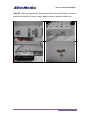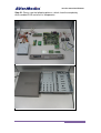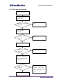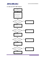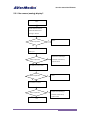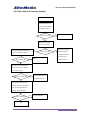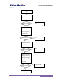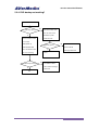
1
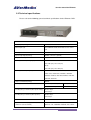
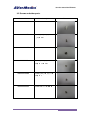
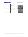
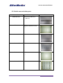
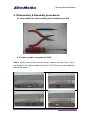
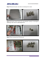
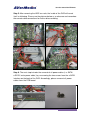
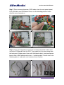
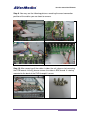
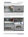
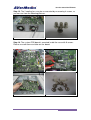
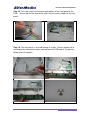
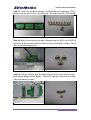
2010
AVerMedia
®
AVerDiGi EH5216+
Service Manual
®
AVerMedia
AVerDiGi EH5216+
Version 1.0
2010/1/1
Service manual for EH5216+
Table of contents
1. Version history of service manual ………………………………………...3
1.1. Version history……………………………………………………………………………….3
2. About this service manual ……………………………………………………...4
2.1. Legal information & disclaimer…………………………………………………………….4
2.2. Technical specifications…………………………………………………………………….5
3. Parts list …………………………………………………………………………………….8
3.1. Main modules………………………………………………………………………………..8
3.2. Screws and other parts……………………………………………………………………11
3.3. Outside case and other parts……………………………………………………………..13
4. Disassembly & Assembly………........................................................................14
4.1. Tools needed………………………………………………………………………………14
4.2. To disassemble and assemble the DVR………………………………………………..14
5. Troubleshooting procedures ………………………………………………..25
5.1. None UI related …………………………………………………………………………...25
5.1.1.
What should I do if the unit is not booting? …………………………………26
5.1.2.
What should I do if there is no local VGA / BNC display? ………………...27
5.2. UI related …………………………………………………………………………………..28
5.2.1.
What should I do if there is no camera (analog) display? ………………....29
5.2.2.
What should I do if there is no camera (IP camera) display? …………….30
5.2.3.
What should I do if the network function is not working? …………………31
5.2.4.
What should I do if the DVD backup is not working? ……………………...32
5.2.5.
What should I do if the audio is not working? ………………………………33
5.2.6.
What should I do if the HDD is not recording? ……………………………..33
5.2.7.
What should I do if the pointing device is not working? …………………...33
5.2.8.
What should I do if the remote control is not working? ……………………34
5.2.9.
What should I do if the front panel control is not working? ………………..34
5.2.10. What should I do if the unit shuts down unexpectedly? ……………….......34
2
Service manual for EH5216+
1. Version history
Version Released date
1.0
1/1/2010
Description
Editor
Approved by
First version
Erick
Jackie/Karen
3
Service manual for EH5216+
2.About this service manual.
2.1 Legal information & disclaimer.
Initial information
This guide is a troubleshooting reference used for maintaining and servicing
the DVR EH5216+. It provides comprehensive information on identifying DVR
features, components, and spare parts; troubleshooting DVR problems; and
performing DVR disassembly procedures.
The target users of this document are our value customers and customer
service teams.
No part of this document may be copied, reproduced, or transmitted by any
means, without prior written permission from AVerMedia® Information,Inc.
AVerMedia® Information,Inc will not take the responsible of the losses of those
unauthorized and misuse by third parties.
Warning
Only authorized technicians should repair this equipment. All troubleshooting
and repair procedures are detailed to allow only subassembly-/module-level
repair.
Because of the complexity of the individual boards and subassemblies, do not
attempt to make repairs at the component level or modifications to any printed
wiring board. Improper repairs can create a safety hazard.
Any indication of component replacement or printed wiring board modification
may void any warranty or exchange allowances.
Caution
To prevent static damage to components inside your DVR, discharge static
electricity from your body before you touch any of your DVR's electronic
components. You can do so by touching an unpainted metal surface.
4
Service manual for EH5216+
2.2 Technical specifications.
Please refer to the following general technical specifications for the EH5216+ DVR.
Electrical specifications
Camera Inputs (analog)
16 BNC connectors
Camera Inputs (IP)
16 CH MPEG4/ JPEG /H.264 data streams from IP
cam
Video output
VGA Out x 1, Composite out x 2
Loop Through Outputs(analog)
16 BNC connectors (optional)
Composite video signal
1 Vpp, 75 Ohm
Recording resolution (analog inputs)
PAL:
352 x 288 (CIF), 720 x 576 (D1)
NTSC:
352 x 240 (CIF), 720 x 480 (D1)
Recording resolution (IP inputs)
2560x1200, 1920X1200, 1600X1200, 1440X1280,
1440X 1080, 1280X1024, 1280X960, 1024X768,
800X600, 720X576, 720X 480, 640X480, 352X 288,
352X 240, 320X 240
Compression Method (analog)
Recording rates
Recording rates per channel (video inputs analog)
MPEG4
CIF(NTSC/PAL)
D1(NTSC/PAL)
480/ 400 fps
240/ 200 fps
NTSC:0-30 fps
PAL:0-25 fps
Recording rates per channel (video inputs IP)
NTSC:0-30 fps
PAL:0-25 fps
Preview resolution
PAL: 720 x 576
Supported IP cameras (support IP PTZ, IP IO, and
AXIS, Panasonic, SONY, Arecont, Mobotix, BOSCH,
IP audio if IP cameras built-in)
NTSC: 720 x 480
VGA: 1024 x 768
IQinvision, JVC, TOSHIBA, VIVOTEK, ACTi, D-Link,
5
Service manual for EH5216+
PiXORD, PELCO, Apron, Lilin and more
Audio Inputs
16-ch line-in signal,8 KHz sampling rate (optional)
Audio Output
1-ch line-out signal
Microphone Input
1-ch line-in signal
Alarm Inputs
16
Input voltage: max. 6 VDC
Relay Outputs
4
Voltage range: 125VAC - 30 VDC
Switching current: max. 1A
PTZ control (analog)
Protocol supported:
Pelco-D, Pelco-P, DynaColor, Lilin, CD55, DiGiDome,
YoKo, MicroJack-P, Cannon(VC-C4R),
Panasonic(CS859/CW860), Samsung(SCC-641),
JVC(TK-C676), JVC(TK-C675), Sony(EVI-D70P),
Philips(TC8560/TC700), ELMO(PTC-200C), Fastrax
II(HID-2404), AmericanDynamics_Ultra, DMP23-H2,
MD101, Sony(15-cz45-1)
Storage capacity support
Support up to 4 SATA HDD (1 removable, 3 internal)
eSATA support
Support eSATA RAID
Ethernet
10/100/1000Base-T, bandwidth-limited
RS 485 port
1, Terminal Block, Tx+, Tx-, Rx+, Rx-
RS 232 port
1, 9 Pin, Male
USB 2.0
3
DVD writer
Included; supported medias: DVD±R, DVD±RW
Power Input
Power adapter; 19V DC
Typical power consumption
approx. 72W
Power consumption
max.80 W
Operating system
Embedded Linux, Graphical User Interface
Operator Interface
Front panel keypad, USB mouse, USB PC keyboard,
remote controller(support optional IR extension cable)
Web Browser (Remote Client)
Microsoft Internet Explorer 6 or higher, on Windows
2000, XP, VISTA, Windows 7
Export of video/audio data
AVerMedia format
Mechanical facilities
Dimensions(H x W x D)
65x430x370 mm
Weight
4.6 KG (Not include HDDs)
Environmental conditions
6
Service manual for EH5216+
Operating temperature
0 °C to +40 °C (32 ° to 104 °F)
Storage temperature
-30 °C to +60 °C (-22°F to 140 °F)
Relative humidity in operation
50%-80%
Relative humidity when stored
90%
Electromagnetic Compatibility (EMC)
USA
FCC Part 15, Class A
EU
EN 55011(Group I, Class A)
EN 61000-3-2: 2000, Class A
Safety
EU
EN 60950-1: 2001+A11:2004
7
Service manual for EH5216+
3. Parts list.
3.1 Main modules.
Part number
Part description
51F2X8NP00AD
GM_EH5216 LITE_AVI_0_VER
Picture
B
51C2A9NP00AG
GM_SEB5116_AVI_0_VIDEO
IN
51C2A9NP00AC
GM_SEB5116_AVI_0_IR
51C2A9NP00AH
GM_SEB5116_AVI_0_POWER
51F2X8NP00AB
GM_EH5216_AVI_0_USB
51C2A9NP00AB
GM_SEB5116_AVI_0_FUN.NU
M(2 IN 1)
8
Service manual for EH5216+
Part number
Part description
Picture
51C2A9NP00AD
GM_SEB5116_AVI_0_CONTRO
L
51C2A9NP00AB
GM_SEB5116_AVI_0_FUN.NU
M(2 IN 1)
064APOWERBHF
CABLE-ATX CABLE-760mm
064AOTHERBFS
CABLE-POWER SWITCH
&
IR-410mm
064AOTHERBFW
CABLE-FUNCTION
&
CONTROL-200mm
064AOTHERBHB
CABLE-USB*3
&
NUMBER-200mm
0700DVD--AKJ
COMPUTER-DVDROM-DRW-I
HAS324/BLACK
9
Service manual for EH5216+
Part number
064AOTHERBFJ
Part description
Picture
CABLE-SERIAL ATA
CABLE-500mm
064ASATA-BDV
CABLE-SATA TO E-SATA-40CM
067AG252PAAV
WIRE-2.5*2P-15CM-JIE LI
064AOTHERBGA
208AC2F1-ADX
CABLE-UL2651-16C-150mm
電線固定板
PLASTIC-
(FWA-22C)
041312GOOAK3
ADAPT-AC/DC-100V~240V/19V
-4.74A
0410KDE12AB5
FAN-KDE1205PFV2-550mm
10
Service manual for EH5216+
3.2 Screws and other parts.
Part number
Part description
207AAAAAAAAN
PSUPOT-TH11-11mm
100AAAAAAAEG
SCREW_MU_I
100AAAAAAADD
SCREW-MU-M3*4
100AAAAAAAH5
100AAAAAAADH
㎜_NI_尾 TP1
頭_T_M2.6*8
扁頭
頭_T_1.7*5 ㎜
_NI_頭徑 4.5-尾 TP3
SCREW_BI
SCREW_MU_F
_NI_
100AAAAAAAG4
Picture
頭徑 5
頭_M_3*5 ㎜
皿頭-鍍
SCREW-MU-5-8-TP-
鎳
11
Service manual for EH5216+
Part number
100AAAAAAAFD
Part description
SCREW_MU_P
_NI_
100AAAAAAAG6
尾 TP1
SCREW_MU_I
_NI+
頭_T_3*8 ㎜
Picture
頭_M_3*5 ㎜
耐落_頭徑 5.5
12
Service manual for EH5216+
3.3 Outside case and other parts.
Part number
200AF2X8-BV6
102AF2X8-ASX
Part description
前面板(金
PB-F2X8-N19B-
綠)-EH5216+
上蓋(金
MTBOX-N20B-F2X8-
綠)
補強桿
112AC2A9-AKA
METAL-C2A9-
112AC2A9-AKE
METAL-C2A9-HD
102AF2X8-ASW
MTBOX-N20B-F2X8-
112AC2A9-AKB
Picture
固定架(3IN1)
下蓋(金
綠)
光碟固定架
METAL-C2A9-
13
Service manual for EH5216+
4. Disassembly & Assembly procedures.
4.1 Tools needed for disassembling and assembling the DVR.
4.2 To disassemble / assemble the DVR.
Step 1. Initially, please have unscrew the 8 screws of the outer case. These
are located in left, right and back side of this DVR. Please see the following
pictures for details.
14
Service manual for EH5216+
Step 2. Remove the outer case after unscrewing the 8 screws.
Step 3. Afterwards, please remove the iron protection steel by unscrewing two
mounting screws. See the following pictures.
Step 4. Please remove the HDD iron rack.
15
Service manual for EH5216+
Step 5. After removing the HDD iron rack, the inside of the DVR will reveal
itself as following. Please use the pictures below as a reference and remember
the correct cable connections for further disassembling.
Step 6. The next step includes the removal of all power cables (i.e. SATA /
e-SATA / main power cable ) by unscrewing the two screws from the e-SATA
interface on the back of the DVR. Accordingly, please unmount all power
cables from the PCB board.
16
Service manual for EH5216+
Step 7. Please remove the power / SATA cables from the main power board,
DVD-ROM drive and PCB board. Please see the following pictures for the
detailed removal procedure.
Step 8. In the next step please remove all remaining connection cables from
and to the PCB board inside the DVR. Those cables are the one coming from
the front panel (Yellow, green, blue and 3 thick black cables), front panel power
board, video in BNC board and two fans – including cables. Please refer to the
following pictures and make sure to remove them carefully.
17
Service manual for EH5216+
Step 9. You may see the following pictures revealing the exact connection
position of the cables you are about to remove.
Step 10. After removing all the cables insides the unit, please start removing
the PCB boards. Initially, please remove the video-in BNC board. It is being
mounted to the back of the DVR through 6 screws.
18
Service manual for EH5216+
Step 11. After removing the video-in BNC board, please remove the main
power board located next to it. Please refer to the following pictures.
Step 12. Once the main power board has been removed, please follow up by
disassembling the main system PCB board - the biggest PCB board inside the
unit. Please unscrew all remaining screws from the back of the DVR and make
sure to removing the two fans before taking out the main PCB board. Please
see the following pictures.
19
Service manual for EH5216+
Step 13. The 2 cooling fans may be un-mounted by unscrewing 4 screws, as
you can see from the following pictures.
Step 14. The system PCB board is mounted inside the case with 9 screws.
Please unscrew them and take out the board.
20
Service manual for EH5216+
Step 15. This step reveals the removal procedures of the front panel of the
DVR. Please loosen the lace which holds the connection cables of the front
panel.
Step 16. The front panel is secured through 3 screws. Please remove these
and unplug the connection cables coming from the PCB board. The pictures
below reveal the details.
21
Service manual for EH5216+
Step 17. Once the front panel has been removed, please remove the 3 PCB
boards from the plastic case. Unscrew total 10 screws from the 3 PCB boards.
Step 18. After the front panel has been removed from the DVR, the USB PCB
board has to be removed from the metal case by unscrewing 3 screws. Please
refer to the following pictures.
Step 19. The last remaining PCB board inside the metal case holds the front
panel power button and the power- / HDD-LED indicator. Please disassemble
it by unscrewing 4 screws.
22
Service manual for EH5216+
Step 20. The final step reveals the removal of the internal DVD drive. To do so,
please unscrew the 4 screws, which hold the drive inside the metal case.
23
Service manual for EH5216+
Step 21. Please see the following pictures, which show the completely
disassembled DVR and all of its components.
24
Service manual for EH5216+
5. Troubleshooting Procedures
5.1 (None UI related issues)
25
Service manual for EH5216+
5.1.1 DVR does not boot up?
Start
Reseat AC adapter in DVR
and wall outlet
DVR booting – check front
Y
Done
Y
Done
LED & FAN
N
Try different wallpower-outlet
DVR booting – check front
LED & FAN
N
Try different ext. AC adapter
(if applicable)
DVR booting – check front
Y
Replace external AC-adapter
LED & FAN
N
Open DVR – check for loose
cables, reseat cables, close
DVR and retest
DVR booting – check front
LED & FAN
N
Replace following items if
available:
int. main power
cable, power board, system
Y
board
End
26
Service manual for EH5216+
5.1.2 No local VGA / BNC display?
Start
Check monitor power
connection and proper
cable connection to
DVR – reseat cables
Video output OK?
Y
Done
N
Use different
VGA-connection cable
Video output OK?
Y
Done
N
Check monitor
brightness settings
Video output OK?
Y
Done
N
Replace system board
N
Try using different
monitor
Video output OK?
Y
End
27
Service manual for EH5216+
5. Troubleshooting Procedures
5.2 (UI related issues)
28
Service manual for EH5216+
5.2.1. No camera (analog) display?
Start
Check cable link and set
camera & DVR-channel
settings to default
Video output OK?
Y
Done
N
Connect camera to different
BNC-input
Replace the following if
Video output OK?
Y
available: video board,
system board
N
Use different video cable
Video output OK?
Y
Done
N
Replace the following if
N
Use different camera
Video output OK?
available: video board,
Y
system board
End
29
Service manual for EH5216+
5.2.2. No camera (IP camera) display?
Start
Check cable link and
set camera & DVR-CH
settings to default
Video output OK?
Y
Done
N
Use computer (IE) to
test camera display
Check DVR network settings and
Y
Video output OK?
try to reach DVR through PC
N
IP-camera problem;
Re-check camera
network connection
Video output OK?
Y
or exchange to
Done
another camera
N
Check IP-cam support-list for
camera model and supported
connection modes.
Camera in support-list?
N
Contact Sales dept. on
integration request
Y
Check camera model, video
format, resolution, IP-address
and camera-authentication
settings in DVR software
Video output OK?
N
Contact NVD-FAE
Y
End
30
Service manual for EH5216+
5.2.3. No network?
Start
Check if network
funct. is enabled in
DVR software
NW-connection OK?
Y
Done
Y
Done
N
Reseat network cable
in DVR jack and
router. Use another
network cable
NW-connection OK?
N
Check DVR network
settings (DHCP, static
IP, PPPoE)
NW-connection OK?
Y
Done
N
Check local network
settings, restrictions &
NW-logs and change
DVR settings
accordingly
NW-connection OK?
N
Contact NVD-FAE
Y
End
31
Service manual for EH5216+
5.2.4. DVD backup not working?
Start
N
DVD tray opens?
Shut down DVR, open
the unit and reseat
Y
DVD-drive power
cables. Re-test.
Ensure inserted media
is an empty
DVD-R/DVD+R,
DVD tray opens?
DVD-RW/DVD+RW
Use different SATA
power cable &
Y
disc. Use different disc
for cross-checking.
DVD backup working?
N
exchange DVD drive
Done
N
Use different SATA
data cable & exchange
Y
DVD drive
End
32
Service manual for EH5216+
5.2.5. No audio?
- Check audio connectors and reseat cables
- Check volume level of connected speakers
- Enable audio recording in DVR menu
- Check volume/mute settings in DVR software
5.2.6. HDD recording not working?
- Cross-check HDD model with HDD support list available on our website
- Open DVR, check HDD connectors and reseat cables
- Use different SATA/power connector and cable if available
- Try accessing the HDD, when mounted into your PC system
- Ensure recording is turned on within DVR software
- Check the remaining storage space available
- Check schedule and recording type settings
- Switch to always recording mode for testing purposes
5.2.7. Pointing device not working?
- Verify pointing device to be fully functional using PC or different DVR
- Use another pointing device
- Try plugging the pointing device into different USB-port if available
- Open the DVR unit and reseat the USB-front panel connection cables
33
Service manual for EH5216+
5.2.8. Remote control not working?
- Check batteries within your remote control and exchange to new ones
- Make sure to point at the IR-receiver at the front receiver and verify if nothing
blocks the visual connection between the remote control and the receiver
- If using an optional IR-extender cable, make sure it is plugged in correctly and
enabled within the software (only EB-series)
- Make sure to set the remote control to the correct DVR-ID before usage (only
EB-series)
- Try using a different remote control if available
5.2.9. Front panel control not working?
- Try different front panel-buttons and verify if all controls are not working
- Double check whether the unit is still operating normally by attaching an external
input device. Try accessing menus and entering the playback mode.
- Open the unit and make sure all front panel connection cables are seated correctly
5.2.10. DVR shuts down unexpectedly?
- Check wall power plug for sudden power failure
- Reseat power cable in AC-adapter and wall outlet. Try using another power cord
- Check AC adapter for obvious damage (water, etc.) and replace if available
- Open the unit and make sure all fans are working correctly – check if their spinning
is probably being blocked by dust. The unit may shut down due to overheating
- Check the internal power board for obvious damage
- Start up the DVR and check the “Schedule” options for reboot settings
- Check the event log to find details about the abnormal reboot (remote reboot, etc.)
34