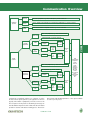
1
Data Communication Introduction
Data Communication Explained
Data communication is fundamentally a simple operation. Point
A sends information to Point B and Point B receives it. A slightly
more complex, and more practical, system allows Point A to send
information to and receive information from Point B, and vice
versa. It is what lies between points A and B that has been the
substance of data communication system development since
before the personal computer, or any computer for that matter,
was ever invented.
For example, consider several simple examples of data
communication systems that have nothing to do with computers:
Paul Revere used a very basic system, whereby one light in the
tower signified the British were approaching by land, and two
indicated they were approaching by sea. During a game of blindman's-bluff, the subject hears a sound when he comes within a
certain distance of an object, and nothing when he is out of
range. To solve the problem of knowing when dishes in a
dishwasher are clean or dirty, a family might decide to place a
black magnet on the dishwasher when dirty dishes are put in,
and then change it to a white magnet when the cleaning cycle is
started, and return the black magnet after it is emptied. The one
thing all these examples have in common is that they all use
two-state systems of communication. A two-state system is one
which uses only two possible values to transmit information-the lamp is on or it is off, there is a sound or there is silence, the
magnet is black or white, etc. The way these values are combined
allows complex messages to be transmitted using very simple
tools.
Consider Morse Code, a two-state data communication system
that functions very similarly to today's computerized data
communication systems. Developed by Samuel E.B. Morse in
the 19th century, Morse code uses electrical current to transmit
a series of dashes and dots that represent letters of the alphabet,
numbers, a comma and a period. A basic Morse Code transaction
works as follows: A "message" is given to an operator who
translates that message into dots and dashes (Point A), then the
transmitting operator uses the telegraph key to send an electrical
signal to the receiving operator at the desired location to indicate
that a message is about to come through. The receiving operator
(point B) sends back an acknowledgment that he is ready, and
the transmitting operator then sends the message which the
receiving operator takes down. When the message is completely
transmitted, the transmitting operator signals to the receiving
operator that he is done, and the transmission line is closed. The
receiving operator then translates the code back into the original
message, and delivers it to the designated recipient.
10
Clearly, in a system of this type, accuracy is extremely important.
As only two characters--dot or dash--are used to create a code
for an entire language system, the transmitting and receiving
operators must be extremely accurate. (Indeed, it makes a big
difference whether the message says "Give one million dollars to
Ted" or "Give one million dollars to Ned"--an easy mistake to
make using Morse code, as the letter T is "-" and the letter N is
"-.") This system can only work if both sides of the data
communication system know the code and can encrypt and
decode messages. It is also essential that the transmitter not
send faster than the receiver can take-down the information.
Even using expert operators, static on the line could obscure
the signals making a dash sound like a dot and thereby corrupting
the message. Thus, it becomes obvious that the most important
aspect of designing a data communication system is ensuring
not only that Point B can receive and understand the data
transmitted by Point A, but also that the data remain uncorrupted
during transmission.
These are the very same concerns faced by computerized data
communication system designers. Indeed Morse code is often
though of as the forerunner of the computer's binary
communication system. The binary system uses the numbers 0
and 1 as the symbols for transmission of data. Using positional
notation, any value is represented by a weighted series of 1s
and 0s. Thus the decimal number "33" would be represented
by "100001" (1 x 25 + 0 x 24 + 0 x 23 + 0 x 22 + 0 x 21 + 1 x 20).
The above is a simple example of binary coding, but the same
system is used by computers to transmit complex text messages,
complex graphics, and streaming video. In order to accurately
transmit many different types of data, numerous interfaces and
protocols have been created. When selecting the appropriate
equipment for your data communication application, it is
important to examine both your application and the
communication peripherals that must be incorporated into the
system. First, determine whether your application is best suited
for a wired system using cables or whether you need a wireless
solution. Also determine whether you need a portable system
using a laptop computer, or a desktop PC or Server. After deciding
upon your host computer, determine the ports available, and
the type of expansion boards this computer can best
accommodate. Then, decide which of those options will best
meet the speed and versatility demanded by your application.
Once you've selected an interface, you can then begin to look at
the type of data communication adapter you will need. You
must also consider the distance you will need between the
www.quatech.com
Communication Overview
Wireless
System
Bluetooth
Bluetooth peripherals, e.g. PDA, mobile phone, printer, modem, etc.
802.11b
802.11 wireless LAN networks and corresponding peripherals, e.g. printers, modems
RF
Modem
Data transfer between compatible sources, e.g. PC-PC or PC-PLC
IEEE 1394 peripherals, e.g. video and still cameras
IEEE 1394
USB Peripherals, e.g. printer, scanner
USB
PCMCIA
or
CardBus
RS-232
RS-422
RS-485
USB Serial
Adapter
Standard
or
EPP
Parallel
Async.
or
Sync.
Serial
COM
Portable
Application
Number
of
Ports
RS-232
RS-422
RS-485
Wired
System
Data
Communication
Peripherals
IEEE 1394 peripherals, e.g. video and still cameras
IEEE 1394
USB Peripherals, e.g. printer, scanner
Desktop
Application
USB
PCI or
CompactPCI
RS-232
RS-422
RS-485
USB Serial
Adapter
Parallel
Standard
or
EPP
Async.
or
Sync.
Serial
ISA
Printer
Scanner
Plotter
Zip Drive
Tape Drive
CD Drive
Bar Code
Reader
Touch Screen
Mouse
Digital Camera
Modem
Etc.
Number
of
Ports
RS-232
RS-422
RS-485
(Assembling a Data Communication System)
communication peripherals and the host computer, as well as
the data transfer speed required for your application to function
properly. The number of peripherals you need to connect to the
host computer is also important for determining how many ports
must be added via expansion boards or hubs. The above flowchart
provides an overview of this decision-making process. The sections
that follow provide detailed explanations of the options available
at each step in the process.
11
1.800.553.1170
ISA and MicroChannel
Modern 16-bit ISA
The first step in assessing your data communication application
is identifying which peripherals you will need and where you will
need them. While in the past your choice of peripherals may
have limited your options, today just about any serial or parallel
device is available in portable form. Many of them are also
available, or soon will be, for wireless networks.
There are no set rules for deciding between portable and desktop
systems, or wired and wireless systems. However, common sense
is your best guide. If your application requires traveling to
multiple locations to download data, such as accessing an
airplane's flight recorder from the cockpit for use in fleet
maintenance, then a portable system could be an appropriate
choice. However, if you are using a central computer to service
a network of touch screens in a restaurant, then a desktop system
might best serve your needs. If you are attempting to install a
network in a factory to monitor equipment for preventive
maintenance, running wires may be a problem, making a wireless
system with high noise tolerance an ideal choice. See pages 3640 in this section for application examples which cover a wide
range of data communication systems. If you need help designing
the optimal system for your application, call one of Quatech's
expert sales engineers. We'd be pleased to help.
ISA
This modern ISA bus emerged in 1984 when it became clear to
IBM developers that the advances made on the processor front
had rendered the XT bus archaic. The first of these new
processors--a 286--was designed to run at 8MHz with a full 16bit data bus. IBM's PC/AT used this processor and contained an
8MHz bus to match it. Still limited by the two-clock-cycle data
transfer, the new AT bus can reach speeds of only 8 Mbytes/sec.
The AT bus provides 16 data lines and 24 address lines, thereby
taking full advantage of the 16-bit addressing limit of the
microprocessor. This improvement over the XT expands a PC's
capability to accept add-in boards by including additional
interrupts and DMA (direct memory access) channels. The ISA
system, however, does not have a central registry from which to
allocate system resources. Consequently, each device behaves
as though it has sole access to system resources such as DMA, I/
O ports, IRQs, and memory. Obviously, this can cause problems
when using multiple add-in boards in a single system.
Another problem is caused by the limited number of available
ports and interrupts on the system. Quatech has solved this
problem for the ISA bus by developing a series of drivers which
allow multiple devices to share the same interrupt. These drivers
are available for Windows 3.1/95/98/NT, OS/2 and DOS. They
permit any of Quatech's multi-port ISA serial adapters (see page
43 for selection guide) to share interrupts amongst themselves
and with any other Quatech ISA serial device. To avoid confusion,
our boards contain a register which will indicate the source of
any interrupt.
In The Beginning
The Industry Standard Architecture or ISA bus began as part of
IBM's revolutionary PC/XT released in 1981. However, it was
officially recognized as "ISA" in 1987 when the IEEE (Institute of
Electrical and Electronics Engineers) formally documented
standards governing its 16-bit implementation.
This first XT bus was intended to allow the addition of system
options which could not be fit onto the motherboard. This XT
bus was completely under the microprocessor's direct control,
and its addressing width was limited to the 8-bit level of the
processor. To make the bus useful, control lines were added to
signal interrupts for input/output ports.
Bus speed was also limited to match the processor. The PC/XT's
8088 was a one-byte wide 4.77 MHz processor. Thus the XT
bus, which required two clock cycles for data transfer, was limited
to an excruciatingly slow (by today's standards) 2.38M bytes/
sec, that could be curtailed even further if the system was busy
with other tasks.
12
ISA For Data Communication Applications
As shown in the table on the next page, ISA is the slowest and
most limited of the bus options available today. If your want a
Pc-based board-level solution, PCI appears to be the most logical
choice. However, in practice there is no speed difference between
running many serial communication peripherals using a PCI rather
than an ISA bus. (Though the PCI advantage is obvious for
high-speed devices such as video cards.) This is because of
limitations inherent in the serial communication protocols (see
page 25 for a discussion of serial communication). Thus Quatech's
DSC-100 two port RS-232 serial PCI adapter has the same
maximum baud rate as does our DS-100S two port RS-232
enhanced serial ISA adapter--115k bytes/sec (921.6 k bits/sec),
well below the maximum 8M bytes/sec ISA limitation.
ISA cards are more cumbersome to install than other cards because
I/O addresses, interrupts and clock speed must be set using jumpers
and switches on the card itself. The other bus options that use
www.quatech.com
Communication Overview
Type of Bus
Bus Clock Signal
Bus
Width
Theoretical
Max. Transfer
Rate
Advantages
Disadvantages
ISA
8 MHz
16-bit
8 Mbytes/sec
low cost,
compatible with older systems
low-speed
jumper & DIP switches
becoming obsolete
MCA
10 MHz
32-bit
40 Mbytes/sec
higher speed than ISA
obsolete
PCI
133 MHz
64-bit
1 Gbytes/sec
CompactPCI
33 MHz
64-bit
132 Mbytes/sec
PCMCIA
10 MHz
16-bit
20 Mbytes/sec
USB 1.1
n/a
n/a
1.5 Mbytes/sec
IEEE 1394a
n/a
n/a
50 Mbytes/sec
software to set these parameters are called Plug and Play. While
there is nothing inferior about using jumpers and switches, it
can be more intimidating for novice users.
The bottom line is that there is no reason to convert your current
low-speed ISA serial communication systems to PCI, as ISA will
provide equivalent functionality, generally at a lower price.
However, many PCs now do not contain ISA slots, and the ISA
interface is fast on its way to being phased out completely. If
you are starting a new installation using a PC without ISA slots, if
you prefer using Plug and Play boards, or you have a high-speed
application, then you should consider using a different interface.
MicroChannel
A Good Idea Which Never Caught On
MicroChannel was introduced in 1987 by IBM as a solution to
the inadequacy of the ISA bus. However, because MicroChannel
(MCA) was prohibitively expensive, and since it was not backward
compatible with older systems, the bus never caught on. It merits
brief discussion here because design features first implemented
in the MicroChannel architecture are at the heart of all subsequent
bus designs.
Improvements Over ISA
The MCA bus itself, operating at 10MHz, was not enormously
faster than its ISA predecessor, but its implementation provided
for dramatically increased system performance. With MCA, IBM
took bus control away from the processor and set up a system of
incompatible with older systems
can cost more
lower speed than PCI
needs adapter for PC use
incompatible with older systems
lower speed
needs special drive for use in PCs
slower than PCI and IEEE 1394
not compatible with older peripherals
not compatible with older peripherals
short communication distance (4.5M)
COM
very high speed
plug and play
dominant board-level bus
designed for industrial use
hot swapping/plug and play
ideal for embedded systems
ideal for portable systems
hot swapping/plug and play
low cost
ideal for portable systems
hot swapping/ plug and play
up to 127 devices via 1 port
high speed
peer-to-peer communication
hot swapping/plug and play
up to 63 devices via one port
hardware-mediated bus sharing, whereby individual devices could
temporarily take control of the system. This significantly lightened
system overhead and allowed for much faster processing. In
some systems the MCA bus could reach speeds of 40M bytes/
sec, a significant improvement over ISA.
MCA improved over ISA in other ways as well, such as allowing
4-byte data transfers. To minimize interference, a ground or a
power supply conductor was located within 3 pins of every signal.
With the bus mastering feature, the MCA bus allowed multiple
devices to compete for system resources at once. To avoid
potential conflicts this could create, a burst mode feature was
designed, which would exclusively allocate system resources to
a single device for 12ms periods.
The First Plug and Play Boards
Another large improvement in the MCA architecture was the
introduction of Plug and Play boards. Gone was the necessity to
set jumpers and cables, MCA cards are automatically configured
using a utility program which reads a unique identity number
coded into a board's firmware. An MCA system uses CMOS
memory to remember its system configuration. At setup it
compares its file to the hardware installed, and makes necessary
adjustments. The identity numbers on each board correspond to
instructions indicating how the board should function within
the system hierarchy. All MCA boards use the same setup
procedure which is totally handled by the system, making the
process appear seamless.
13
1.800.553.1170
PCI
PCI
CPU
A New Standard
First released in 1992, the Peripheral Component Interface (PCI)
has rapidly evolved into a viable replacement for the ISA bus,
and is the most commonly used method for adding boards to a
PC. It solves many of the problems with older architectures,
while at the same time delivering a substantial increase in
processing speed. PCI provides a new way of connecting
peripherals to both the system memory and the CPU, with the
goal of alleviating many problems encountered when installing
new cards in an ISA based system (IRQ conflicts, address conflicts,
etc.). To ensure the longevity of the bus, not only are systems
based on newer PCI specifications backward compatible with
those designed to older ones, PCI boards may also be used in a
system that also employs other types of devices.
Strict Rules
To ensure that every PCI card will function properly in every PCI
enabled system, a committee, the PCI Special Interest Group,
was formed to set and manage standards for the bus. Quatech
is a voting member of this committee, and all Quatech PCI
products strictly adhere to the standards.
The most important of these standards is the requirement that
all PCI cards implement specific configuration registers. Whether
the PCI device is embedded on the PCI bus, or is an add-in
board as Quatech's products are, it must include a unique "Vendor
ID" and "Device ID," and a resource requirement list on its
configuration registers. Any card which does not contain these
registers cannot be considered a true "PCI" adapter, and might
not work properly in your system. See pages 16-17 for a detailed
discussion of PCI compliance issues and a comparison of Quatech
boards vs. non-compliant PCI boards.
Plug and Play
Implementing PCI control registers is vitally important to ensuring
that Plug and Play, one of PCI's most attractive features, works
properly. Setting jumpers and switches to configure address
and IRQ is not required. The system configures itself by having
the PCI BIOS access configuration registers on each add-in board
at boot-up time. As these configuration registers tell the system
what resources they need, (I/O space, memory space, interrupts,
etc.), the system can allocate its resources accordingly, making
sure that no two devices conflict.
14
PCI-to-PCI bridge
PCI Bus 7
PCI-to-PCI bridge
PCI Bus 6
PCI-to-PCI bridge
PCI Bus 5
PCI-to-PCI bridge
PCI Bus 4
SRAM
North-Bridge
DRAM
PCI Bus 0
PCI Bus 0
ISA Slot
PCI-ISA
Bridge
PCI-to-PCI bridge
PCI Bus 3
PCI-to-PCI bridge
PCI Bus 2
PCI-to-PCI bridge
PCI Bus 1
ISA Slot
ISA Slot
(PCI Bus System with 8 PCI Busses and a PCI-ISA Bridge)
While this method is ideal for an exclusively PCI system, it does
pose problems for systems using both ISA and PCI, because PCI
BIOS cannot directly query ISA devices to determine which
resources they need. Using a PCI-ISA bridge (see diagram above)
to enable communication can help.
Another implication of the PCI implementation is that a board's
I/O address and interrupt are not fixed, meaning that they can
change every time the system boots. Consequently, application
software written for ISA boards, which are hard-wired to particular
interrupts, will not directly transfer to PCI-based systems. This is
a serious consideration when contemplating switching to PCI.
The High Speed, Wide Bandwidth Advantage
More than any other bus, PCI can take full advantage of today's
high-power microprocessors to deliver extremely high speed data
transfers. The original PCI bus was designed to operate with a
33MHz clock, to provide data transfer speeds up to 132 Mbytes/
sec. These 32-bit adapters can use multiplexing to achieve 64bit data transfers. (Later versions of PCI enable true 64-bit data
transfers using up to a 133MHz clock to enable transfer speeds
of up to 1066 Mbytes/sec.) These boards use a longer connector
that adds an additional 32-bits of data signals. This is done by
using the same set of pins to address and send data, the former
implemented on the first clock cycle and the latter on the second.
PCI's burst mode facilitates this operation as it allows a single
address cycle to be followed by multiple data cycles. A special
bus signal called a Cycle Frame is used to signal the beginning
and end of a transfer cycle. Parity signals are used to ensure
signal integrity, which is particularly vulnerable in such a complex
transfer system.
www.quatech.com
Communication Overview
Flexible Bus Mastering
Several pins on the PCI bus are reserved for implementing bus
mastering. This means that any PCI device can take control of
the bus at any time, even allowing it to shut out the CPU. Devices
use bandwidth as available, and can potentially use all bandwidth
in the system if no other demands are made for it. Bus mastering
works by sending Request signals to the Central Resource
(circuitry on the motherboard shared by all bus devices) when a
device wants control of the bus, and when that control is ceded
a Grant signal is received by the device. This flexible approach,
which separates the arbitration and control signals (they were
bussed together on MicroChannel and ISA), allows a computer
designer greater control over the arbitration process.
Interrupt sharing on the PCI bus is also implemented to provide
maximum flexibility. Four level-sensitive interrupts are located
on the bus at pins A6, B7, A7 and B8, each of which can be
assigned to from one to 16 separate devices. These interrupts
can be activated at any time because they are not synchronized
with the other signals on the bus. The PCI specification does
not define how interrupts are to be shared. The process is
implemented on a case-by-case basis by the motherboard
manufacturer. For instance, Quatech multi-port serial PCI boards
require only one slot to provide up to eight serial ports. These
eight ports share a single interrupt, and our boards provide an
interrupt status register that will indicate which of the eight ports
triggered an interrupt.
Looking Ahead
The PCI-X specification is a high-performance enhancement to
the PCI bus specification. It doubles the maximum clock
frequency that can be used by PCI devices from 66 MHz to
133Mhz, thus enabling communication at speeds over 1 Gbyte/
sec. It also improves the efficiency of the PCI bus itself and the
devices attached to it, by providing new features such as split
transactions and transaction byte counts. PCI-X was developed
for applications such as Gigabit Ethernet, Fibre Channel and other
Enterprise server applications.
PCI Specification 3.0 is due for release in late 2001. This
specification is largely based on PCI-X, and is intended to solidify
the extensive changes made to PCI since the release of
Specification 2.1. It also addresses a number of power
issues designed to make PCI systems more efficient.
COM
The high speed data transfers across the PCI bus limits the number
of PCI expansion slots that can be built into a single bus to 3 or
4, as opposed to the 6 or 7 available on the ISA bus. To expand
the number of available expansion slots, PCI-to-PCI bridges are
used. (See diagram left.) These bridges create a primary and a
secondary PCI bus, each of which is electrically isolated from the
other. Multiple bridges can be cascaded, theoretically allowing
unlimited numbers of PCI slots to be configured in a single system.
(Practically, it is important not to overload the CPU, as adding
too many devices via expansion slots could considerably
compromise system bandwidth.) The bridge enables bus transfers
to be forwarded upstream or downstream, from one bus to
another until the target/destination is reached.
Clearly, traditional PCI add-in boards are not practical for
portable systems or for systems that use small-size cases.
Two new standards have been developed that address
these issues: Low Profile PCI and Mini-PCI. Low Profile PCI
was designed to provide greater flexibility in desktop and server
environments. The card is mechanically similar to a standard PCI
card, but uses a shorter card and a different mounting bracket.
(See the figure below).
Low Profile PCI cards are designed to fit into systems as low as
PCI Expansion Board
Low Profile PCI
Expansion Board
(Relative sizes for PCI and Low Profile PCI boards)
Continued on page 18
15
1.800.553.1170
PCI
Quatech guide to choosing a quality PCI communication board
The PCI bus specification was designed to take the guesswork
out of choosing and installing add-in boards. Unlike the ISA
bus, where each board had to be jumper configured by hand,
then incorporated into an existing system at a specific address
and IRQ that did not conflict with anything else installed in that
system, the PCI bus was supposed to let the system itself take
care of everything. By developing a strict set of hardware and
software parameters, the architects of PCI mapped out a system
by which PCI cards could be allocated resources by the BIOS.
This way the BIOS itself could solve and resolve any addressing
or interrupt conflicts occurring as a result of multiple PCI boards
coexisting with each other and with other system devices--without
user intervention. However, a PCI system is only as strong as its
weakest link. In order for the system to consistently function
properly, all installed PCI boards must completely adhere to all
aspects of the PCI specification, and in a perfect world they
would. But, complete adherence to the exacting PCI specification
not only requires extensive engineering expertise, it also requires
the purchase of top-quality components and meticulous board
design and manufacturing.
16
Quatech has been manufacturing communication boards for over
18 years, so we have the expertise to do it right. We are also
committed to providing only top-quality boards and to investing
the necessary resources to ensure that every Quatech PCI board
complies with all aspects of the PCI specification as closely as
possible. Unfortunately, not all companies have the same high
standards we do. Therefore, users need to remember that just
because a board is calling itself "PCI" and fits into a computer's
PCI slot, that does not mean that it correctly implements the PCI
specification. While a non-compliant PCI board may seem to
work when it is first installed, it might cause problems when
combined with other PCI boards (especially other non-compliant
boards), or when moved to a different motherboard, or when the
PCI bus is heavily stressed. Is that really a chance you are
willing to take with your system?
We know that Quatech boards aren't your only choice, but we
truly believe that there aren't any better ones. The chart below
details the important PCI specification compliance issues to keep
in mind when evaluating PCI boards. The following page
highlights the design elements you should look for in a quality
PCI board, and shows what is missing in a non-compliant one.
Compliance Issue
Importance
Quatech
Boards
Other Manufacturers
All unused 5V and 3.3V power pins are
plated on the connector (goldfingers)
Better data integrity because high-speed PCI
signals use the power pins for return paths
YES!
Sometimes, often ommitted when
"cutting corners"
All 3.3V power pins are decoupled from
ground with capacitors
Better data integrity because high-speed PCI
signals use the power pins for return paths
YES!
Rare, ground return path capacitors
are often omitted
All PCI signal lines have one and only one
load (connected to only one pin on one
component on the board)
Better data integrity because the PCI bus is
extremely sensitive to signal loading
YES!
Usually, but sometimes violated
JTAG boundary scan chain intact if unused
(connect TDI and TDO signals)
JTAG boundary scan systems can work with
the board installed
YES!
Extremely rare
Trace length of 1.5" or less on PCI signals
PCI signals rely on specific travel times up and
down the bus. Proper trace lengths ensure
data integrity
YES!
Usually, but sometimes violated
PCI clock trace is 2.5" ±0.1" in length
PCI clock signal timing is particularly critical.
All other PCI signals depend on accurate clock
delivery
YES!
Often violated
Full PCI configuration space implemented
So that plug-and-play really works
YES!
Almost always, but there are some
exceptions
www.quatech.com
Communication Overview
Look closely at the PCI card you are considering buying. Does it comply with
all aspects of the PCI specification? Quatech boards do. Can you really afford
the potential aggravation of using a non-compliant board in your system?
Notice the two tight rows of
"gold fingers" on the Quatech
board. This indicates that all
PCI signals and power pins are
plated, even those that are
unused. The result is better
data integrity because highspeed PCI signals use the
power pins for return paths.
Is your board truly Plug and Play or
do you see jumpers for setting basic
configuration parameters such as address?
The Quatech board contains a
controller chip in which all PCI
configuration registers are
properly implemented. This
means that the PCI BIOS can use
the information stored on the
chip to automatically configure
the Quatech board, making it
truly Plug and Play.
The non-compliant board has no
controller chip, and basic
configuration settings such as
address and IRQ must be
selected manually via jumpers on
the board. Not only is this board
not Plug and Play, it has the
potential to conflict with other
PCI devices in the system.
Notice the loosely spaced
goldfingers and the large
gaps on the non-compliant
board. This indicates that
not all pins are plated, and
that data integrity may be
compromised.
Do you see large "pools" or "grids" of ground
signals running all over the board?
Notice that there are no grids
apparent on the surface of the
Quatech board. This is because all
Quatech boards have a four-layer
board design using separate layers
for power, ground and signals thus
reducing noise and enhancing signal
integrity.
Do you NOT see a row of tiny capacitors
(usually rectangular) just above the edge
connector on the front or back of the board?
back of board
front of board
COM
Do you see blank spaces on the edge connector
instead of a complete row of gold-plated pins?
Notice the grids of ground signals
on the front and back of the noncompliant board. This indicates
the lack of a separate ground layer
and complicates signal routing.
This makes the board more
susceptible to noise and can
compromise signal integrity.
back of board
Capacitors which connect
the power signal to a
ground are part of the PCI
specification and are
designed to filter out noise.
As it is fully PCI compliant,
the Quatech board includes
these capacitors. The
capacitors also promote
signal integrity, as highspeed PCI signals use the
power pins for return paths.
Notice that the non compliant
board is missing the required
capacitors. This omission
makes the board particularly
vulnerable to noise problems
and loss of signal integrity in
high-speed operations.
17
1.800.553.1170
PCI and CompactPCI
3.350" with out using riser cards. There are two types of Low
Profile PCI boards: MD1 and MD2. Both are built on 32-bit
addressing, and differ only in length (MD1 being shorter than
MD2.) Systems can be designed to support one or both
configurations. Existing PCI backplanes used for standard cards
can also accept the Low Profile cards. However, the Low Profile
specification also includes a new bracket design that cannot be
used with standard PCI boards.
Mini PCI, on the other hand, is not backward compatible with
any older devices. It is designed to be used by system integrators
to add additional functionality for mobile computers. It requires
a completely new interface, and is typically used to add
communication peripherals such as modems and network interface
cards to notebook computers, docking stations, or sealed case
PCs.
Mini PCI boards are even smaller than Low Profile boards, with a
minimum size specification of 2.75" x 1.81" x 0.22." They are
functionally equivalent to standard and Low Profile boards, using
the same protocols, PC signals and software drivers. However,
because of the small size they require higher density, more
compact, and thus more expensive components. So, while Mini
PCI is extremely useful for the mobile applications for which it
was intended, it is not the most economical or flexible choice for
desktop expansion.
PCI for Data Communication
PCI is fast becoming the de facto standard for board-level
expansion slots in PC-based systems. However, for serial and
parallel communication, the potential of PCI goes largely
untapped. Limitations of these communication protocols
considerably slow down the system. (See pages 25-28 for more
on serial and parallel communication.) The PCI specification
anticipates this situation, and the bus is designed to slow down
when dealing with low speed devices. So, though running serial
and parallel devices via a PCI bus will not cause system problems,
neither will it significantly improve system performance over ISA.
But, as ISA slots are fast becoming obsolete, you may have no
choice but to use PCI add-in boards in newer systems. For
higher speed devices such as audio, streaming video, interactive
gaming, high-speed modems, etc., PCI provides a clear advantage
over older bus architectures.
PCI competes with both USB (see page 22) and IEEE 1394 (see
18
page 24) for high-bandwidth applications. All three provide the
advantage of Plug and Play installation, which may be important
to some users. Currently, only USB and IEEE 1394 support hot
swapping, but support for it is planned in a future PCI
specification. USB has been positioned as a low cost solution
for a variety of desktop applications. IEEE 1394 is used mainly
for video applications. However, PCI still has a speed advantage
when using true 64-bit data transfers. In fact, in many systems
USB or IEEE 1394 ports are added to a system via the PCI Bus
(see Quatech's TFC-100 page 69).
CompactPCI
PCI for Industrial Computers
CompactPCI is based on the electrical functionality of desktop
PCI and the Eurocard physical form factor. It is designed for
ruggedized applications in industrial environments. CompactPCI
boards have several features that make them ideal for embedded
systems or for industrial PCs:
• High density 2mm pin and socket connectors
• Designed for vertical card racks for better cooling
• Excellent vibration and shock protection characteristics
• Shield for EMI/RFI protection
• I/O connections on front or rear of module
• Staged power pins for hot swapping
Form Factor
The key to the CompactPCI bus is a gas-tight, high-density pin
and socket connector that meets the IEC-1076
international standard (pictured below).
(CompactPCI 220 pin connector)
Its low inductance and controlled impedance make it ideal for
PCI signaling. The connector uses a 2mm "Hard Metric" connector
and has 47 rows of 5 pins per row, with a total of 220 pins (15
pins are used for the keying area). An additional external metal
shield is also used. The large number of ground pins ensures
adequate shielding and grounding for low ground bounce and
reliable operation in noisy environments. By controlling
impedance, the connector can minimize signal reflections.
www.quatech.com
Communication Overview
CompactPCI Systems
Ejector Handle
(Quatech QSCP-100, 3U CompactPCI board)
CompactPCI boards must follow one of two size specifications
and have ejector handles that are IEEE 1101.10 compliant. 3U
boards measure 100mm x 160mm, and 6U boards measure
233.53mm x 160mm. The 3U boards have a single ejector handle
and use a 220 pin connector for all power, ground, and all 32and 64-bit PCI signals. This connector consists of two halves the lower half (110 pins) is called J1 and the upper half (also 110
pins) is called J2. Twenty pins are reserved for future use. 3U
boards that only perform 32-bit transfers can use a single 110
pin connector (J1). For example, Quatech's QSCP-100 serial
CompactPCI serial board (see page 70) is a 32-bit 3U board
using a single J1 connector. Both 32-bit and 64-bit 3U boards
can be mixed on a single CompactPCI backplane.
233.35 mm
100.00 mm
J4
J3
J2
J1
160.00 mm
J5
The CompactPCI system is made up of CompactPCI bus segments,
each of which has one system slot and up to seven slots for
CompactPCI peripherals (at 33MHz). The system slot is used to
control the peripherals attached to the bus segment. For example,
it provides bus arbitration, clocking, and reset functions, as well
as system initialization functions. It can be located at any position
in the backplane, and must use both J1 and J2 to control both
32-bit and 64-bit peripheral boards. The peripherals in the
remaining seven slots can be simple boards, intelligent slaves or
PCI bus masters. By using PCI-PCI bridge chips, the CompactPCI
bus can be expanded in 8 slot increments.
Peripherals attached to the first four PCI connectors are provided
a unique PCI interrupt. After that, rotating interrupts are
assigned to allow boards to share interrupts. The System
Slot board always has its own interrupt. Rules for interrupt
sharing are derived from the specification governing PCI
bridges. Note that because some devices require more
than one interrupt, interrupt sharing may be required even
if only the first four slots are used.
COM
110 pin J1 Connector
CompactPCI is designed to use both +5V, and +3.3V devices.
+V(I/O) power pins are designed for universal boards that can
operate at either +5V or +3.3V. A keying technology is used to
prevent a board from being attached to the wrong power pins.
Universal boards are not keyed. Backplanes have both +5V and
+3.3V, and, depending on the application, Universal boards can
use either. Typically, for 5V operation a brilliant blue coding
plug is used on the backplane, for 3.3 V operation a Cadmium
yellow coding plug is used. Power terminals can be located on
the front, rear or side of the backplane.
CompactPCI for Data Communication
(CompactPCI form factors for 3U and 6U boards)
6U boards can have up to three additional connectors (J3-J5)
with a total of 315 2mm style pins, and because of their large
size use two ejector handles. The CompactPCI specification only
defines signal-pin assignments for J1 and J2. J-3 through 5 can
be user defined based on application requirements. They can
also be used as a bridge to other buses like VME or ISA in hybrid
backplanes. PICMG is developing future specifications for a
standardized use of the additional connectors.
CompactPCI boards are designed for ruggedized, industrial
environments. They are also ideal for many embedded systems
that are implemented in such environments. Though they are
electrically similar to standard PCI boards, CompactPCI boards
cannot be used in a desktop computer without a special adapter
board. They are made to be used in specialized enclosures
designed to provide both superior protection against
environmental hazards and easy access for rewiring, replacing,
or exchanging peripherals. To that end the pin sequence on the
backplane connector is staged to support hot swapping.
Quatech serial PCI boards with the "IND" option are also designed
for use in industrial environments. However, to implement
protection on the board itself requires sacrificing speed. The
CompactPCI specification is specifically designed for such
environments, and can optimally implement data communication
peripherals in them.
19
1.800.553.1170
PCMCIA
PCMCIA
Application Software
Expanding Portable Systems
Founded in 1990, the Personal Computer Memory Card
International Association (PCMCIA), of which Quatech is a
member, developed a set of standards by which additional memory
could be added to portable systems. It soon became apparent
that this same interface could be used to add I/O devices and
hard disk drives as well, thereby dramatically increasing
functionality of laptop computers. Today, just about any device
available for desktop computers using an ISA or PCI bus is also
available with a "PC-Card" interface for use with laptop computers,
and in some cases, hand-held machines.
Operating
System
BIOS
Flash File System
Memory
Technology
Driver
Memory
Card
Device
Driver
Card
Services
Socket
Services
host
connector to host
PCMCIA
Drive
Physical Characteristics
68 Pin Socket
68 Pin Connector
The PCMCIA specification 2.0 release in 1991 added protocols
for I/O devices and hard disks. The 2.1 release in 1993 refined
these specifications and is the standard around which most
PCMCIA cards are built today.
PCMCIA cards are credit card size adapters which fit into PCMCIA
slots found in most hand-held and laptop computers. In order
to fit into these small size drives, PCMCIA cards must meet very
strict physical requirements as shown in the chart below. There
are three types of PCMCIA cards, Type I generally used for memory
cards such as FLASH and STATIC RAM; Type II used for I/O
peripherals such as serial adapters, parallel adapters, and faxmodems (this is the type of card Quatech manufactures); and
Type III which are typically used for rotating media such as hard
disks. The only difference in the physical specification for these
cards is thickness.
Interface: 68 pins
I/O Connection: manufacturer determined
Length: 85.6 mm
Width: 54.0 mm
Thickness:
Type I
Type II
Type III
3.3mm
5.0 mm
10.5 mm
85.6 mm
Interconnect Area
68-Pin Connector
54.0 mm
Operating Temp:
Storage Temp:
Substrate Area
Type I--3.3mm thick
Type II--5.0mm thick
Type III--10.5 mm thick
0 to 55 oC
-20 to 65 oC
PCMCIA
Card
(Block Diagram of a Basic PCMCIA Expansion System)
Card & Socket Services
Functionally, a PCMCIA card can perform any memory or I/O
operation as long as it adheres to the PCMCIA interface structure.
As shown in the above diagram, PCMCIA is a tiered system that
uses a set of device independent drivers to integrate any type of
PCMCIA card into the host system. Socket Services, the lowest
tier in the architecture, provides a universal software interface for
the PCMCIA sockets themselves. Socket Services manages all the
sockets installed in a system so that resources can be properly
allocated. It is also the means by which individual cards access
registers on the host system. Socket Services can be added to a
computer as a device driver, or it can be built into the PC BIOS.
Directly above Socket Services in the hierarchy sits Card Services.
Card Services is an application programming interface (API) that
permits multiple software programs to work with multiple PCMCIA
cards. For instance, Card Services will allow both internet
applications and fax applications to use an installed PCMCIA card
modem. Like Socket Services, Card Services can be implemented
as a device driver, and can be built into a computer's operating
system, as it is in Windows 95/98/Me/NT/2000 and OS/2.
16-Bit PCMCIA
PCMCIA specification 2.1 provides for a 16-bit bus interface, has
a maximum clock speed of 10MHz and is capable of speeds to
(PCMCIA Card Physical Characteristics)
20
www.quatech.com
Communication Overview
The two most important features of PCMCIA are its Plug and
Play and Hot Swapping capabilities. As with PCI, PCMCIA cards
are truly Plug and Play--you simply insert them, and instructions
coded into chips on the card provide the information a host
needs to configure the cards and appropriately allocate resources.
Not only are there no jumpers or switches to set, users never
even see the inside of a PCMCIA card. It is simply inserted into
the drive, and the system does the rest. (An open PCMCIA card
is pictured below, to show what you've been missing.)
and bus mastering to PCMCIA based systems, which can markedly
increase performance. Realizing that there are still many 16-bit
PCMCIA card peripherals in the marketplace CardBus is fully
backward compatible with the older card design.
Because of this backward compatibility, Quatech has decided
not to redesign our serial data communication PCMCIA cards for
CardBus, as doing so would limit the number of systems that
could use our cards. As discussed with PCI, because of the
limitations imposed by serial and parallel transfers, there would
be no noticeable performance gains for Quatech serial cards under
CardBus. However, our new DFP-100 two port IEEE1394 card,
(see page 57 for card specifications and page 24 for more on
IEEE 1394) does use the CardBus interface. IEEE 1394 peripherals
can communicate at speeds up to 400 Mbits/sec, and
thus can take advantage of the higher speed
communication CardBus provides.
PCMCIA for Data Communication
(Quatech's QSP-100 PCMCIA Card Uncovered)
This configuration procedure, along with the fact that PCMCIA
cards are not connected directly to the motherboard, but are
easily inserted into and ejected from a PCMCIA drive, allows the
cards to be hot swappable. This means that the system need not
be shut down then re-booted to add, remove, or exchange cards.
Thus, you could insert a PCMCIA scanner, scan a drawing of
your newest board layout, then remove the scanner and insert a
modem and e-mail the scan to a manufacturer for mass
production. While this might not be very important for desktop
PCs with large numbers of expansion slots, it is vitally important
for laptops with limited resources and usually only two PCMCIA
slots. It becomes even more important for hand-held computers
which often have only one PCMCIA slot and one serial port.
32-Bit CardBus
In 1995 the PCMCIA 2.1 specification was enhanced to provide
for 32-bit operation. The new architecture, called CardBus, was
closely based on the PCI bus, and strove to provide the same
improvements over the 16-bit PCMCIA card as PCI did over ISA.
As such, CardBus provides for 33MHz operation and
correspondingly increased data transfer. It also introduces DMA
COM
20Mbps. The 2.1 spec. does not provide for bus mastering,
DMA, or multiple interrupts, (however, Quatech's interrupt sharing
software drivers allow sharing the one interrupt among multiple
I/O devices). While PCMCIA provides only a minimal performance
improvement over ISA, and does not come close in speed to PCI,
it does provide for considerably more flexibility than either of
the others.
Though PCMCIA card use is not limited to portable
computers, (see pages 58-60 for PCMCIA drives for desktop PCs)
there are few instances where it is the best choice for data
communication in desktop computers. In desktops, PCMCIA is
better suited for adding extra storage space via hard-disk cards,
or transferring large files from portable systems. However, for
laptop and hand-held computers, PCMCIA provides a way to
connect a varied array of peripherals to the system, and to share
those devices with a desktop computer.
Clearly there is a size advantage to PCMCIA for portable
applications. The cards are small, light, and have low power
requirements. They are an ideal interface choice for peripherals
that have been scaled down for portable use. Further, the ability
to Hot Swap PCMCIA cards provides for the flexibility needed to
use multiple peripherals with only one or two slots. USB and
IEEE 1394, which also provide Hot Swapping, (see pages 2224), are other alternatives for portable applications. IEEE 1394
uses a particularly small cable ideal for portable applications,
and is ideal for high speed audio and video applications. However,
to use USB or IEEE 1394, the peripheral devices in your system
must be replaced with bus specific devices--an expensive
prospect. Further, many USB products must be powered by the
computer itself, thereby reducing the time a laptop can function
on battery alone. Or, if too much power is required, they must
be plugged-in, making them less attractive portable solutions.
So if cost and power conservation are your primary concerns,
PCMCIA is still the best, most flexible choice for portable
applications.
21
1.800.553.1170
USB
USB
Host
The User-Friendly Choice
USB Host
Controller
The Universal Serial Bus (USB) was developed around the idea
that users should be able to run multiple peripherals on their
computers without the hassle of physically installing boards,
manually allocating system resources, individually configuring
devices, and powering the computer up and down every time
equipment needs change. With USB, up to 127 individual
peripheral devices can be connected to a host computer using a
single interface and a system of USB hubs. (See right for a diagram
of a typical USB system.) Attaching a USB peripheral to your
computer is as easy as plugging headphones into your Walkman.
USB devices are automatically recognized and configured. They
can draw power directly from the system, from an attached selfpowered hub, or be connected to their own power supply.
USB Features
USB provides two-way communication between the PC and
peripheral devices, making it ideal for many I/O applications.
Multiple devices can connect to a system using a series of USB
hubs and repeaters. A single USB interface is attached to the
motherboard. A Root Hub with up to seven additional ports can
be integrated into the main interface, or it can be externally
connected with a cable. Each of the seven hubs on the Root
Hub can in turn be connected to seven hubs, etc. to a maximum
of seven tiers and 127 ports. A unique feature of USB is that a
peripheral device can have a hub built into it. This type of
peripheral, called "compound devices," are comprised of a
function device and one or more hubs. For example, a USB
keyboard can contain an additional USB port for a USB mouse.
USB is generally described as having a tiered star topology, however
each device communicates with the host as if it had its own
connection. This means that communication from the host
centers around a set of hubs/devices, each of which in-turn serves
as the center for another set of hubs/devices, etc. However, the
hubs are transparent to the software and the devices are addressed
individually. Cables are used to create point-to-point connections
between devices and USB ports, or to connect one USB hub to
another. The maximum cable length is five meters long. However,
a repeater hub may be used to extend the distance between the
peripheral and the host. There are also special USB repeaters
that can be used to extend the connection even further. (See
page 92 for Quatech's QExtend-4)
Peripheral
Device
Root Hub with ports
Peripheral
Device
HUB
HUB
Peripheral
Device
Peripheral
Device
HUB
Peripheral
Device
Peripheral
Device
Peripheral
Device
= USB Port
= USB Cable, max length 5 Meters
Peripheral
Device
Peripheral
Device
Peripheral
Device
(A Typical USB System)
Operating System support for USB is built into later releases of
Windows 98 and the new Windows 2000. You can find out
whether your system supports USB by downloading an USB
evaluation utility from the official USB website (www.usb.org).
The USB Difference
USB is technically not a bus in the tradition of ISA, MCA or PCI,
as it provides more than a simple interface to the host computer.
Nor is it merely a communication protocol along the lines of
serial and parallel communication which are dependent upon
an external interface to reach the host computer. USB combines
the bus and the communication protocol into a single entity
which connects directly to a peripheral device. (Review the
diagram on page 11 for a better understanding of this difference.)
As such, the USB standard encompasses both the interface and
the method of communication. Whereas, in a PCI-based system
one standard defines the bus (eg. PCI Specification 2.1) and
another defines the communication protocol (eg. RS-232).
Cables and Ports
The Root USB Hub is connected directly to the USB Host, and
from there everything is done with cables. Two types of cables
can be used with USB devices: Series A and Series B. Series B
cables are limited to 3 meters in length and are for use with lowspeed (1.5 Mbps) USB peripherals such as keyboards and mice.
The UTP cable has a pair of 28 AWG wire stranded copper for
data and one pair 20-28 AWG for power.
(Series A USB Port (left) and USB Connector (right))
22
www.quatech.com
Communication Overview
The Series A connector pictured (see bottom left) is for use with
high speed (12 Mbps) devices, and can be up to 5 meters long.
The more common of the two, it consists of one pair 20-28 AWG
wire for power (VBUS is typically +5V at the source) and one 28
AWG twisted wire pair for data. The connector has a shielded
housing, making it STP compliant. (See the drawing of a USB
cable below.)
VBUS
D+
D-
USB 2.0 is fully backward compatible with all older USB devices.
It merely adds another device class--"high speed device." The
USB host controller determines the type of devices attached to it,
and then treats them accordingly. In fact, a high-speed USB hub
can be used for both high, full (12Mbps) and low (1.5Mbps)
speed devices at the same time.
While still relatively new, many manufactures are starting to release
2.0 peripherals. Quatech's serial USB adapters will remain USB
1.1 devices, as even the fastest serial communication is limited
to 10Mbps--well within the range of a full speed device.
USB for Data Communication
(USB Cable)
Power Management
One special feature of USB systems is that they can directly supply
power to the peripherals and the hubs attached to them. It can
also regulate power usage for peripherals that use independent
power sources. USB devices are classified based on the amount
of power they supply or require. Low Bus Power devices take all
their power from the bus, but no more than 100mA at a time.
High bus-powered devices also take all their power from the bus,
but can draw up to 500mA at a time. Self-powered devices use
an external power supply, but can draw up to 1mA from the host
if necessary--such as in the case of a power failure.
Hubs can also be low, high or self powered. Power flows
downstream in a USB system, which means that a self-powered
hub can be used to power high- and low-powered peripheral
devices located further down in the network. This power
arrangement has both advantages and disadvantages. For desktop
systems where power is not a problem, it is extremely convenient
not to have to use a separate outlet for each peripheral connected
to the PC. In notebooks where battery longevity is often a
problem, it might be more advantageous to use peripheral devices
that have their own power source.
Looking Ahead
USB Specification 1.1 was designed for low to medium speed
applications running at less then 12 Mbits/sec. As such it is not
suited for high-end data transfer such as high-speed back-ups
to hard disks or CDs , high resolution color printing and interactive
gaming. The recently released USB Specification 2.0 aims to
upgrade the bus for high performance applications. The main
difference between Specification 1.1 and 2.0 is that the latter
provides for data transfer rates up to 480 kbits/sec.
For low to medium speed data communication applications USB
Specification 1.1 provides a clear usability advantage older
bus types. USB peripherals are both Plug and Play and
Hot Swappable devices. Further, USB is flexible enough
to incorporate up to 127 individual devices into a single
system using only one interface. And, unlike PCMCIA
cards, where the board itself is subject to considerable
wear from multiple insertions and extractions, USB devices
use a connector cable which can be inserted and removed multiple
times without consequence. Because of USB's structure, it can
potentially reduce system downtime considerably.
COM
GND
As a bus option designed for both desktop and portable use,
USB can bridge the gap between desktop and portable peripherals,
provided the new peripherals are designed in small enough form
to be practical for portable systems, and provided they do not
draw too heavily from a laptop's limited battery power.
USB 2.0 with its considerably higher speeds will rival both boardlevel interfaces such as PCI and other interfaces such as IEEE
1394 (see next page). In fact, some computer companies are
pushing for a PC standard that will no longer supply slots for
plug-in boards, and will rely completely on USB and IEEE 1394
type devices. With the knowledge that IEEE 1394 has become
the standard for video applications, USB 2.0 has been positioned
as a more general purpose, and low-cost, solution.
USB's major drawback, one it shares with IEEE 1394, is its inability
to implement peripherals designed for older protocols. As USB
popularity increases, it is becoming more likely that a USB device
exists for any given application. However, software applications
written for non-USB peripherals cannot be implemented using
USB because of the difference in communication protocols.
Quatech has solved this problem with our FreedomUSB serial
adapters (see pages 86-93). With Quatech's FreedomUSB Series
you can take full advantage of USB benefits while continuing to
use your current serial peripherals in your existing applications.
23
1.800.553.1170
IEEE 1394
IEEE 1394
The High-Speed Multimedia Solution
IEEE 1394 is a high-performance serial bus designed for high
speed audio, video and data transfer applications. First introduced
by Apple Computer as “Firewire" in 1986, the standard is now
overseen by the Institute of Electrical and Electronics Engineers
(IEEE). This same standard is also referred to as “i.LINK" by Sony
Corporation which has trademarked that name.
Unlike the other wired busses described so far, IEEE 1394 is
unique in that it does not require a PC in order to function. For
example, IEEE 1394 can be used to send a picture directly from
a digital camera to a printer, or to transfer a file between two
digital video cameras. Another outstanding feature is that IEEE
1394 does not require that digital data be converted to analog.
Thus, provided that a network is comprised of exclusively digital
devices, using IEEE 1394 can considerably improve and maintain
signal integrity--even over multiple transfers of the same data.
Other advantageous IEEE 1394 features are Plug and Play and
Hot Swap capability, and the very small cable size that is ideal for
portable devices.
as streaming video. Isochronous transfers, which guarantee a
steady transfer rate but do not provide any error checking, are
used for such applications. The IEEE 1394 bus reserves space
for both types of transfer to occur in the same network, at the
same time if necessary. The IEEE 1394 network can also support
multiple devices operating at different data rates simultaneously.
IEEE 1394 Cabling
The IEEE 1394 standard includes two cable specifications. The
difference between the two is that the 6-pin connector includes
power and ground pins, allowing one 1394 device to provide
power (up to 60 watts) to others in the network. The 4-pin
connector lacks these power pins, and thus 4-pin devices must
provide their own power. The advantage to the 4-pin connector
is size--the 4-pin (at 5mm x 3mm) is considerably smaller than
the 6-pin (at 10mm x 5mm), and thus better suited for portable
applications. The maximum cable length for high speed
applications (greater than 200 Mbits/sec) is 4.5 meters. However,
at slower speeds, cables up to 14 meters long can be used.
Multiple devices can also be daisy-chained using repeaters to
extend communication distance.
The first IEEE 1394 standard was designed for PC backplanes
and supported data rates of up to 50 Mbits/sec. IEEE 1394a
was approved in 2000, and supports speeds of 100 Mbits/sec,
200 Mbits/sec and 400 Mbits/sec. 1394a, which was designed
to use a cable interface, also provides improved traffic control
and added power management features. To increase speeds
even further, a new specification, IEEE 1394b, is scheduled to be
released in late 2001. The new standard is supposed to increase
IEEE 1394 bandwidth as high as 3.2 Gbits/sec.
6-pin 4-pin
port ports
Both asynchronous (see page 25) and isochronous (see page
28) communication are supported under IEEE 1394.
Asynchronous communication is used for applications such as
writing data to disk, and employs the extensive error-checking
necessary to safeguard signal integrity. However, such error
checking requires a delay that makes asynchronous
communication impractical for time sensitive applications such
24
4-pin
connector
Power conductors (8 to 30 VDC, 1.5A)
6-pin connector only
External cable shielding
Two independently shielded twisted wire
pairs for transmit and receive connections.
(4-pin and 6-pin)
The IEEE 1394 System
IEEE 1394 systems can connect up to 63 devices together via a
single bus connection which may or may not include a computer.
They can be connected in either a star or tree pattern, and multiple
devices can be daisy chained off any branch. Addressing for
these devices is done dynamically each time the system is powered
up, or when a device is added or removed from the network. For
even larger networks, multiple 1394 busses (up to 1,203 busses)
can be bridged together.
6-pin
connector
(IEEE 1394 4-pin and 6-pin connectors)
IEEE 1394 for Data Communication
IEEE 1394 has become the standard for high-speed video
applications. In fact, typical video controls such as play and
rewind have been written into the specifications. 1394 support
is included in Windows 98/Me/2000, making it a good solution
for various high-bandwidth PC-based applications such as data
transfers to external hard disks or video editing. It shares many
of the same features as USB (see page 22), though it is
significantly faster than USB 1.1. USB 2.0 comes close to matching
speed, however most people find the busses complimentary. USB
is a more general standard geared towards desktop peripherals,
and it requires a computer. IEEE 1394 has targeted the multimedia
audio/video market, and it also provides the advantage of allowing
compliant devices to communicate without a PC.
www.quatech.com
Communication Overview
Asynchronous
Most PC serial devices such as mice, keyboards and modems are
asynchronous. Asynchronous communication requires nothing
more than a transmitter, a receiver and a wire. It is thus the
simplest of serial communication protocols, and the least
expensive to implement. As the name implies, asynchronous
communication is performed between two (or more) devices which
operate on independent clocks. Therefore, even if the two clocks
agree for a time, there is no guarantee that they will continue to
agree over extended periods, and thus there is no guarantee that
when point A begins transmitting, point B will begin receiving,
or that Point B will continue to sample at the rate Point A
transmits. See the diagram below for an illustration of what
happens when transmission clocks differ significantly.
Incoming
Data
Sample
Strobe
1
0
S
T
A
R
T
0
Output
Upgraded UARTs For Increased Performance
1
2
3
4
5
6
7
8
S
T
O
P
1
1
0
1
0
1
1
0
a. Best case, receiver samples at mid-point of each bit
Incoming
Data
Sample
Strobe
Output
1
0
S
T
A
R
T
0
(Asynchronous Serial Communication System Model)
1
2
3
4
5
6
7
8
S
T
O
P
1
1
0
0
1
1
0
b. Receiving clock is too slow, causing bit 4 to be skipped
and the data to be corrupted
(Ideal and corrupted asynchronous data sampling)
To combat this timing problem, asynchronous communication
requires additional bits to be added around actual data in order
to maintain signal integrity. Asynchronously transmitted data is
preceded with a start bit which indicates to the receiver that a
word (a chunk of data broken up into individual bits) is about to
begin. To avoid confusion with other bits, the start bit is twice
the size of any other bit in the transmission. The end of a word
is followed by a stop bit, which tells the receiver that the word
has come to an end, that it should begin looking for the next
start bit, and that any bits it receives before getting the start bit
should be ignored. To ensure data integrity, a parity bit is often
added between the last bit of data and the stop bit. The parity
bit makes sure that the data received is composed of the same
number of bits in the same order in which they were sent. See
the diagram (above right) for a portrayal of how asynchronous
communication works.
COM
The Simple, Inexpensive Choice
At the heart of every asynchronous serial system is the
Universal Asynchronous Receiver/Transmitter or UART. The UART
is responsible for implementing the asynchronous communication
process described above as both a transmitter and a receiver
(both encoding and decoding data frames). The UART not only
controls the transfer of data, but the speed at which
communication takes place. However, the first UARTs could only
handle one byte of information at a time, which meant that the
computer needed to immediately process any transmission or
risk losing data as the next byte of information pushed its way
onto the UART. Not only does this makes for unreliable and slow
communication, it can slow down the entire system.
Improved UARTs, such as the 16750 UARTs, increase
communication speed and lower system overhead by offering
64-byte FIFOs (first in first out buffers). With the 64-byte FIFO
buffer, the UART can store enough information that the data
stream need not be suspended while the computer is busy. This
is particularly helpful in heavy multi-tasking operating systems
such as Windows 95/98/Me/NT/2000 and OS/2.
Enhanced Serial Adapters for Even More Speed
Even with 16750 UARTs, serial boards with a standard 1.8432
MHz clock can only reach speeds of 115.2 kbits/sec. This is
because the UART sets the baud rate by dividing down the clock
frequency, and the lower the clock speed, the lower the possible
data rate. The standard clock on Quatech serial boards can be
multiplied by a factor of one, two, four, or eight by using jumper
or software controls. High baud rates, up to 921.6 kbits/sec, can
be produced through a combination of changing the clock rate
multiplier and the UART baud rate divisor.
25
1.800.553.1170
Synchronous Communication
Synchronous
not only that all devices in the system be synchronized with
each other, but also that each individual device have its
transmission and reception lines synchronized as well.
Coordinated Speed
As its name implies, synchronous communication takes place
between a transmitter and a receiver operating on synchronized
clocks. In a synchronous system, the communication partners
have a short conversation before data exchange begins. In this
conversation, they align their clocks and agree upon the
parameters of the data transfer, including the time interval
between bits of data. Any data that falls outside these parameters
will be assumed to be either in error or a placeholder used to
maintain synchronization. (Synchronous lines must remain
constantly active in order to maintain synchronization, thus the
need for placeholders between valid data.) Once each side knows
what to expect of the other, and knows how to indicate to the
other whether what was expected was received, then
communication of any length can commence.
The theory behind asynchronous and synchronous
communication is essentially the same: Point B needs to know
when a transmission from Point A begins, when it ends, and if it
was processed correctly. However, the difference lies in how the
transmission is broken down. Think of the difference in terms of
a friendly chat. With asynchronous communication you would
need to stop after every word to make sure the listener understood
your meaning, and knew that you were about to speak the next
word. With synchronous communication, you would establish
with your listener that you were speaking English, that you will
be speaking words at measured intervals, and that you would
utter a complete sentence, or paragraph, or extended soliloquy,
before pausing to confirm understanding. Further, you would
establish with your listener beforehand that any extraneous noises
you make during the speech or between speeches (coughing,
burping, hiccupping) should be ignored. Clearly the second
approach is much faster, even though initializing communication
may take slightly longer. In fact, by replacing the start, stop and
parity bits around individual words with start, stop and control
(processing instructions and error checking) sequences around
large continuous data blocks, synchronous communication is
about 30% faster than asynchronous communication, before any
other factors are considered.
Clock Synchronization
In order to initiate a successful synchronous communication link,
several distinct pieces of hardware must be configured around a
common clock. This configuration must take two data lines into
account, the transmission line (the line it uses to send data) and
the reception line (the line it uses to receive data). It is essential
26
There are three clocking methods by which to achieve
synchronization: internal, external, and recovered clocking. All
three methods derive the clock signal for the reception line from
the incoming data. The clock signal for the transmission line will
always be generated by the devices internal oscillator, but the
phase reference used by the internal oscillator differs for each of
the clocking methods. When internal clocking is used, the transmit
clock is phase locked to the device's own internal oscillator. For
external clocking, the transmit clock is phase locked to the phase
of the oscillator belonging to another device in the network. For
recovered clocking, the transmit clock phase is locked to the
clock derived from the incoming data.
In general, the DCE device (such as a modem) uses internal
clocking, while the DTE device (such as a PC) uses external
clocking and synchronizes around the DCE device. (See page 30
for a detailed description of DTE and DCE devices.) In cases
where DTE-DTE or DCE-DCE connections are necessary, one device
must be configured atypically, or a device such as a modemeliminator or tail-circuit buffer must be placed between the two.
However, in large networks with multiple devices this is not always
possible. One solution for such networks is to have all devices
synchronize around a single modem's clock source. However,
this solution has the tendency to result in clock drift, and thus
can potentially corrupt data. The other solution is to use recovered
clocking so that a modem can derive the clock from data on its
reception line then send that information out on its transmit line
to be used by the next modem in line, etc.
Byte-Oriented Synchronous Protocols
Synchronous communication can be implemented for full and
half-duplex networks using bit- or byte-oriented protocols. Halfduplex networks, whether point-to-point or multipoint, can only
support communication in one direction at a time. The most
commonly used protocol for such networks is IBM's Binary
Synchronous Communication Procedures (BiSync). BiSync is a
byte oriented protocol, which means that it approaches transmitted
data as “blocks" that must each be decoded and tracked to
determine what they are, and what they are telling the receiver
to do.
In a BiSync system one computer is designated as a control station.
It is responsible for initiating all data transfers, and thereby
controlling the direction of flow on the communication line. Byteoriented communication begins with establishing synchronization,
www.quatech.com
Communication Overview
it then establishes communication parameters that define
instructions for processing given bit sequences. Finally, the actual
data will be transmitted, and then followed by several frames
that validate the transmission. BiSync transmission is also
governed by a strict set of rules for data transmission. These
rules require frequent handshaking and validation--speaking in
sentences rather than paragraphs between pauses. As a result of
the extensive handshaking, and because communication can take
place in only one direction, BiSync communication is best suited
for low-speed applications.
Hub go-ahead: Uses one inbound and one outbound channel.
The primary sends on the outbound channel and the
secondaries send on the inbound channel. Secondaries pass
messages through each other back to the primary.
Key to SDLC communication is the control characters it uses to
maintain data integrity. The figure below shows the six fields
that comprise a single SDLC data frame.
Flag
Address
Control
Bit-Oriented Synchronous Protocols
Data
Frame
Check
Sequence
Flag
(SDLC Data Frame)
Clearly, bit-oriented communication requires considerably less
overhead than byte-oriented communication, because it is not
constantly attempting to match bit sequences to numerous
predetermined arrangements. The only sequence the bit-oriented
protocol is concerned with identifying is the flag sequence. Bit
protocols have other advantages over byte protocols as well. In
a byte-oriented system, because of the constant handshaking,
communication can take place in only one direction at a time.
In bit-oriented systems, both ends can talk to each other at once,
enabling effective use of full-duplex networks. Further, a single
master device using bit protocols can communicate with multiple
slave devices by using an address field following the start of
message flag. This address field is tailored to each individual
slave, and slaves only process data that is specifically addressed
to them. Likewise, when the master receives from the slave, it
knows from precisely where the transmission originated.
The Flag field starts and ends error checking. The Address field
is used to indicate the intended data destination, and can
be a single address, a group of addresses, or a broadcast
to the entire network. The Data field is the information
being transmitted, and the Frame Check Sequence (FCS)
is generally a Cyclic Redundancy Check (CRC) calculation.
A calculation on the transmitted data is done by the
transmitter and the result is sent in the FCS. This calculation is
then performed by the receiver after data transmission is complete.
If the results don't match, an error is assumed.
COM
In bit-oriented protocols, data is accepted as a long string of bits
whose order does not impart specific instructions to the receiver.
Data is flagged by a set bit pattern at either end, and is validated
by a single frame check sequence at the end of the message that
either accepts it or demands retransmission. Any bits received
outside of valid flag sequences are ignored as placeholders.
The Control field uses three different formats depending on the
type of SDLC frame. The diagram below breaks out the different
data bits in the control field. Explanations for the three control
formats follow on the next page.
The two main bit-oriented protocols used today are Synchronous
Data Link Control (SDLC) and High-Level Data Link Control (HDLC).
SDLC, which was developed by IBM in the 1970s, is based around
a network of primary and secondary network nodes. The primary
controls the network and continually polls the secondaries to
determine whether they have data to transmit. Four
configurations are available for SDLC networks:
Point to Point: one primary connected to one secondary
Multipoint: one primary connected to multiple secondaries
Loop: one primary connects to the first and last secondary,
and secondaries in the middle pass messages through
each other to the primary.
Control Field (1 or 2 bytes)
Receive
Sequence
Number
Poll
Final
Send
Sequence
Number
0
Information Frame Format
Receive
Sequence
Number
Poll
Final
Function
Code
0
1
1
1
Supervisory Frame Format
Function
Code
Poll
Final
Function
Code
Unnumbered Frame Format
(Control Field Formats for SDLC Frames)
27
1.800.553.1170
Synchronous and Isochronous Communication
The Information Frame is used when actual data is being
transmitted. It is also used to provide sequencing, flow and
error control functions. The sequence number bits are used to
indicate the number of the frame that will be sent/received next,
and are used by both the primary and secondary nodes. The
Poll Final bit is used by the primary to tell the secondary whether
or not an immediate response is required. The secondary uses
the Poll Final bit to indicate whether the current frame is the last
in its response, or whether more frames are coming.
The Supervisory frame is used to control the communication
network. It can request or suspend data transfer, report status,
and acknowledge receipt of data. Note that since Supervisory
frames are used exclusively for control, they do not have data
fields.
The Unnumbered frame is unsequenced, can contain one or two
bytes, and is used to provide miscellaneous control commands.
For instance, it might be used by a primary node to activate the
secondary nodes in the network.
Another bit-oriented synchronous communication protocol, High
Level Data Link Control (HDLC) which is based on SDLC, also
uses the frame format described above. However HDLC, which
was approved by the International Standards Organization (ISO)
in 1979, differs from SDLC in several ways. With HDLC, 32-bit
checksums can be used, thereby providing an advantage over
SDLC in the sophistication and accuracy of error checking, and
thus data integrity. Unlike SDLC, HDLC protocols cannot operate
using loop or hub go-ahead configurations (see page 27).
The largest difference between the two, is that SDLC uses only a
single transfer mode, while HDLC provides three choices. Both
use Normal Response Mode (NRM) in which a secondary node
is precluded from communicating with a primary node until the
primary gives permission. The two additional HDLC modes are
Asynchronous Response Mode (ARM) and Asynchronous Balanced
Mode (ABM). In ARM mode, any secondary can initiate
communication without receiving permission from the primary.
ABM mode requires that all devices be configured as combination
nodes that, depending on the situation, can assume the role of
primary or secondary in the network. In such a system, any
device can initiate communication at any time without permission.
Data Buffers
Though synchronous communication enables transmission of
large amounts of data at high speed, it puts in place extensive
control and error-checking mechanisms to prevent data
28
corruption. However, in full-duplex networks using bit-oriented
protocols, the transmitter is most likely sending frame B before it
knows if frame A was received successfully. (This is not as much
of a problem in slower byte-oriented protocols where data flows
in only one direction at a time.) To maintain the highest possible
data rates, synchronous hardware must contain sufficient data
buffers to store transmitted data (for resending if necessary) until
a successful transfer is confirmed.
Quatech synchronous serial PCMCIA (see page 54-55) and PCI
(see page 68) cards use a 1024-byte FIFO for data buffering.
Our ISA synchronous cards (see page 81-83) use DMA. All support
both bit and byte protocols, and point-to-point and multipoint
full- and half-duplex networks. We also supply SYNCDRIVE
software (see page 56) with all synchronous cards. SYNCDRIVE
provides hardware specific device drivers, DLLs and APIs to simplify
incorporating Quatech boards into your BiSync, SDLC and HDLC
applications.
Isochronous
A steady data stream
Unlike asynchronous and synchronous communication, which
both involve elaborate error checking mechanisms, the driving
force behind isochronous communication is a fast, steady,
uninterrupted data stream. Isochronous clocking information is
derived from or included in the data stream, and the delay factor
is dependent on a channel's characteristics and can be logically
determined. Communication can be disrupted if the transmitter
does not maintain a constant transfer rate, or if the receiver has
an insufficient buffer to store data at the rate it is arriving and
then hold it until it can be processed by software. To maintain
data transfer speed, error checking is often omitted. Though
software can be written to track errors, there is no hardware
mechanism by which to request retransmission of corrupted data.
Isochronous communication is best suited for applications where
a steady data stream is more important than accuracy. A good
example is video conferencing where infrequent small “blips" in
the data stream are tolerable, however, long pauses between a
transmission and a response are not.
To ensure that isochronous transfers are not bogged down by
other devices, the USB specification sets aside bandwidth for
them. IEEE 1394 also uses isochronous communication, as it is
ideal for the high-speed video and audio applications for which
the bus was designed.
www.quatech.com
Communication Overview
The previous sections have discussed ways in which data is
transmitted and received. However, we have yet to discuss what
happens to the data between Point A and Point B. This inbetween area is a cable made up of wires through which data
travels. Specifications for this cable were developed to maximize
signal integrity (to limit the possible degradation that could be
caused by external noise or ground shifts). There are three main
methods for asynchronous and synchronous communication: RS232, RS-422 and RS-485. Differences between the three are
highlighted in the chart below and in the descriptions which
follow. The other option is parallel communication, which is
described on page 32. As noted earlier, when using USB, IEEE
1394, or any of the wireless interfaces, cabling is part of the bus
specification.
when compared with a ground. Because signals traveling this
single wire are vulnerable to degradation, RS-232 systems are
recommended for communication over short distances (up to 50
feet) and at relatively slow data rates (up to 20 kbps). However,
in practice, these limits can be exceeded.
Data
Signal
Transmitter
Data
Ground Return
(Unbalanced, Single-wire Transmission)
Transmitter
Signal
Data
COM
Data
Data
Data
RS-232
(Unbalanced, Two-wire Transmission)
The First Standard
RS-232 was introduced in 1960, and is currently the most widely
used communication protocol. It is simple, inexpensive to
implement, and though relatively slow, it is more than adequate
for most simple serial communication devices such as keyboards
and mice. RS-232 is a single-ended data transmission system,
which means that it uses a single wire for data transmission.
(Since useful communication is generally two way, a two-wire
system is employed, one to transmit and one to receive.) Signals
are processed by determining whether they are positive or negative
Mode of Operation
DTE and DCE: Serial Communication Partners
A typical system is made up of two types of device, data
communication equipment (DCE) and data terminal equipment
(DTE). Typically DTE is defined as the communication source,
and DCE is defined as the device that provides a communication
channel between two DTE-type devices. For example, the diagram
on page 25 shows two modems (DCE) providing the
communication channel between a PC and a mainframe, two
DTE devices.
RS-232
RS-422
RS-485
Single-ended
Differential
Differential
1
1
32
Drivers per Line
1
10
32
Maximum Cable Length
50 feet
4000 feet
4000 feet
Maximum Data Rate
20 kbps
10 Mbps
10 Mbps
Driver Output Maximum Voltage
±25V
-0.25V to +6V
-7V to +12V
Driver Output Signal Level (loaded)
±5V
±2V
±1.5V
Receivers per Line
±15V
Driver Output Signal Level (unloaded)
Driver Load Impedance
3k
to 7k
±5V
100k
n/a
±5V
54k
n/a
±100µA
±100µA
±100µA
30Vµs max.
n/a
n/a
Receiver Input Voltage Range
±15V
-7V to +7V
-7V to +12V
Receiver Input Sensitivity
±3V
±200mV
±200mV
Maximum Driver Output Current (Power On)
Maximum Driver Output Current (Power Off)
VMAX/300
Slew Rate
Receiver Input Resistance
3k
to 7k
4k
min.
12k
min.
29
1.800.553.1170
RS-232 and RS-422/485
In order for DCE and DTE devices to communicate with each
other, two wires must be used--one for transmission and the
other for reception--and both devices must not use the same
wire for the same purpose.
Should this happen, nothing
would get communicated
because both devices would
be talking on the same line
and listening to a line on
which nothing is transmitted.
To solve this problem, DTE and
DCE devices have complementary
pinouts to allow terminals and
modems to be connected directly
using a one-to-one cable (see
above-right).
Situations arise in which no DCE device is needed, such as a
desktop computer communicating with a laptop. In this case, a
null modem cable or modem eliminator cable is used to connect
the two DTE devices. This cable effectively changes the wires
the second device uses for transmission and reception (see aboveleft) to assure that both sides can communicate.
Connectors: The Communication Conduit
As discussed in the asynchronous and synchronous
communication sections, there is more to a serial transmission
than simply data. Additional information must be transmitted
between both ends of a conversation to make sure that when
Point A sends, Point B is listening, and vice versa. This is called
handshaking. These handshaking lines take-up considerable space
on a serial connector.
Connectors for RS-232 devices are always constructed using
standard assignments for the wires in a RS-232 cable in order to
maintain the DTE-DCE relationship described above. These
connectors can be modular (phone jack) or male D-shell (pins
configured in a rough "D" shape which fit into sockets on the
device). The signal assignments for the RS-232 wires follow.
The descriptions reference the standard D-9 and D-25 connectors
used by most serial devices, however the definitions are applicable
to modular connectors as well (though in modular connections
not all of the handshaking signals are implemented). Pages 62,
70-73 and 78 detail Quatech modular adapters for PCI,
CompactPCI, and ISA, and include modular connector pinout
information.
30
RS-232 Signal Descriptions
Abbreviations used in the following definitions of RS-232 wire
functions will be used throughout the catalog.
DTR: Data Terminal Ready--Used by a DTE to signal that it is
plugged in and available to begin communication.
DSR: Data Set Ready--Sister signal to DTR, it is used by the DCE
to indicate it is ready to begin communication.
CTS: Clear to Send--Used by DCE to signal it is available to send
data, and also used in response to an RTS request for data.
RTS: Request to Send--Used by a DTE to indicate that it wants
to send data. Also, in a multi-drop network, used to turn carrier
on the modem on and off.
DCD: Data Carrier Detect--Used by a DCE to indicate to the DTE
that it has received a carrier signal from the modem and that real
data is being transmitted.
RI: Ring Indicator--Used by a DCE modem to tell the DTE that
the phone is ringing and that data will be forthcoming.
TxD: Transmit Data--This wire is used for sending data.
RxD: Receive Data--This line is used for receiving data.
GND: Signal Ground--This pin is the same for DTE and DCE
devices, and it provides the return path for both data and
handshake signals.
Synchronous Communication Only
TxCLK: Transmit Signal Element Timing--Used by DTE to provide
DCE with timing information for data transfer.
RxCLK: Receiver Signal Element Timing--Used by DCE to provide
DTE with timing information for data transfer.
LLBK: Local Loopback--Used by DTE to make sure the local
transmit and receive interface is functioning properly.
RLBK: Remote Loopback--Used by DTE to make sure a remote
transmit/receive interface is functioning properly.
TEST MODE: Test Mode--Used by DCE to indicate that it is testing
itself in response to a local or remote loopback signal from a DTE.
5
4
9
8
3
7
2
1
14
3
15
5
4
16
17
6
18
8
7
19
20
9
21
10
22
11
23
24
12
13
25
GND
1
2
GND
2
3
4
5 6
6
D-25: Black pins always used
D-9
1
Green pins for synchronous only
all pins used
White for asynchronous only
www.quatech.com
(RS-232 Serial Connectors)
Modular
all pins used
Communication Overview
Balanced Transmission
The RS-422 protocol greatly expands the practical possibilities
of the serial bus. It provides a mechanism by which serial data
can be transmitted over great distances (to 4,000 feet) and at
very high speeds (to10 Mbps). This is accomplished by splitting
each signal across two separate wires in opposite states, one
inverted and one not inverted. The difference in voltage between
the two lines is compared by the receiver to determine the logical
state of the signal. This wire configuration, called differential
data transmission or balanced transmission, is well suited to noisy
environments. With RS-232 communication, which is unbalanced
transmission and uses only one wire, signal degradation can take
place if there is a difference in ground potential between the
transmitting and receiving ends of the cable. With balanced
transmission, this potential difference will affect both wires equally,
and thus not effect their inverse relationship. Twisted pairs of
wire, which ensure that neither line is permanently closer to a
noise source than the other, are often used to best equalize
influences on the two lines. Errors can be caused by high noise
levels affecting one side of the receiver to a different extent than
the other. To combat this, each receiver is generally grounded.
Data +
Data
Rt
Transmitter
Receiver
Two such mechanism's exist: Full-Duplex and Half-Duplex. In
Half-Duplex operation communication can take place in only
one direction at a time. This is an obvious solution to a balanced
system employing only one set of wires--if signals were coming
in both directions at once, they would conflict with each other.
However, even systems in which different pairs of wire are used
for transmission and reception can still operate in Half-Duplex
mode. In such a case, each data exchange is predicated upon
the previous one, and will not take place without proper
handshaking.
In Full-Duplex systems, transmission and reception can occur at
the same time. Thus Point A can send information to Point B
while at the same time receiving data from Point B. Full-Duplex
operation becomes especially important in systems where
a single master is communicating with multiple receivers.
With a Full-Duplex configuration, Point A can send data
to Point B while receiving data from Point C.
COM
RS-422
The nature of a Full-Duplex system lends this configuration
to a network of multiple devices communicating with each
other using a single data line. However, the RS-422 protocol
does not permit this type of communication. With RS-422 there
can be only one driver, though there can be up to 10 receivers.
Thus, only the master Point A can communicate directly with
points B through K. If Point C wants to transmit data to Point H,
it must go through Point A to do it.
Data
RS-485
Data-
The True Multidrop Network
(Balanced Transmission)
Errors in balanced transmission systems such as RS-422 can also
be caused by signal reflections. As data transfer speeds increase
and travel over longer distances, the signal can be reflected back
from the far end of the wire. To combat this, termination resistors
are placed at the far end of the cable which make the cable
appear electrically as if it is infinitely long--infinitely long lines
don't have ends, and thus can't reflect from one end to the
other. These termination resistors will differ depending on the
protocol used. For RS-422 a 100 ohm resistor is placed at the
receiving device.
Full-Duplex, Half-Duplex, and Multipoint Systems
An RS-232 based system allows only two devices to communicate.
With RS-422 a master can use one communication line to converse
with up to 10 slaves. With that many parties wanting to talk, a
mechanism for controlling the conversation must be implemented.
RS-485 is an upgraded version of the RS-422 protocol that was
specifically designed to address the problem of communication
between multiple devices on a single data line. It is a balanced
transmission system that is virtually identical to RS-422 with the
important addition of the ability to allow up to 32 devices to
communicate using the same data line. Thus any Point A through
Point FF can directly communicate with each other, taking on
the role of master and slave as needed. This is achieved with
tristatable drivers which are usually controlled by a programmable
handshake line to ensure that only one device acts as a driver at
any one time.
In such a system, the RS-485 line cannot be thought to have a
beginning and an end, because communication can be initiated
from any point on the line. Thus, terminating resistors must be
placed at both ends of the RS-485 wire to achieve the infinite
line illusion. For RS-485, 120 ohm resistors are placed at the
two furthest points of the communication link.
31
1.800.553.1170
Parallel Communication
Byte
In the Beginning
The original 8-bit parallel port was developed by IBM in 1981 as
a faster interface to dot matrix printers than the then standard
one-bit serial port. The parallel port greatly increases transfer
speeds by using an 8-wire connector that transmits the eight
bits in a byte of data simultaneously, thus sending an entire byte
of data in the time it takes to send a single bit in a serial system.
This byte of data is supplemented by several other handshaking
signals, each sent on its own wire, which ensure that data transfer
takes place smoothly.
The major drawback to the original parallel port or Standard
Parallel Port (SPP) was that it allowed for communication in only
one direction--computer to printer. While there were wires which
the printer could use to indicate its status to the computer, it
could do no more than put a positive or negative charge on
these wires. (See chart below for a comparison of parallel
protocols.) This arrangement effectively limited the parallel port's
potential and precluded it from being used in bidirectional
communication such as is required for external storage devices.
The EPP Advantage
IBM soon realized the advantages to be gained from enabling
the parallel port for bidirectional communication. While early
bidirectional efforts did indeed provide for two way transfer, they
did little to make the parallel port a viable alternative for high
speed data transfer.
To address this problem, a new standard for parallel
communications, known as IEEE 1284 (for the committee which
established it), was approved in 1994. This new standard sought
to correct the major drawbacks to the original parallel port
structure. The first major drawback was that not all parallel
peripherals used the same mechanical interface, and thus the
maximum cable distance between computer and peripheral could
Pin
Byte
1
2-9
Data transmission from computer to pr
10
ACK: Used by printer to tell computer
the transmitted data and is ready for m
11
BUSY: Used by printeer to regulate da
12
PE: Used by printer to tell computer it
13
SELECT: Used to indicate to the comp
14
AUTOFEED: Printer carriage return
15
ERROR: Printer indicates an unspecifi
16
INIT: Computer initializes printer
17
SELECTIN: Allows a printer to be brou
b2
b3
b4
b5
b6
b7
b8
Byte
b2
Byte
b1 b2 b7
b3 b5 b8
b4 b6
Parallel Communication
Byte
b3
b1 b2 b7
b3 b5 b8
b4 b6
b4
b5
b6
b1 b2 b7
b3 b5 b8
b4 b6
b7
b8
(Serial vs. Parallel Communication)
only extend 6 feet. IEEE 1284 sets standards for the cable,
connector and electrical interface that guarantees interoperability
between all parallel peripherals. The specified configuration
ensures that data integrity is maintained, even at the highest
data rates, and at a distance of up to 30 feet.
IEEE 1284 also set design standards for true bidirectional
communication between devices. However, the real advance came
with the Enhanced Parallel Port (EPP). EPP utilizes data cycles
that not only enable bidirectional communication, but also provide
for real-time data transfers by permitting intermixing of block
transfers, read operations and write operations.
The EPP specification also solves the speed problem. Parallel
data transfer was largely performed by software in SPP systems,
and thus data transfer rates were limited to 150 kbps. The new
EPP standard specifies a hardware driven handshake system of
data transfer that allows significantly higher transfer speeds--up
to 2 Mbps. In EPP mode, data transfer takes place as a single
software instruction, and the rest of the transfer is handled by
hardware. This allows an EPP port to function as a 16- or 32-bit
data transfer interface using 8-bit I/O hardware, in effect enabling
EPP peripherals to achieve the same speed and efficiency as
many of their board-level counterparts.
SPP Funct
STROBE: Used by computer to tell pr
character has been transmitted and is
b1
b1
18-25 Ground
32
Serial Communication
b1 b2 b7
b3 b5 b8
b4 b6
www.quatech.com
Communication Overview
Wireless Communication
Interface
Speed
Range
RF Modem
57.6 kbps
500 meters
line-of-sight
802.11b
up to
1Mbps
100 meters
line-of-sight
Windows
98SE/Me/
2000/CE
BluetoothTM
723 kbps
10 meters (with
obstacles)
Windows
98SE/Me/
2000/CE
OS Support
Protocol
Windows
3.1/95/98/Me/ DSSS with GMSK
modulation
2000 and DOS
Antenna
external
DSSS (QPSK and
BPSK with CCK embedded
modulation)
Bluetooth
(FHSS)
embedded
COM
The bus interfaces discussed in the
previous sections all require a wired
connection between PCs and
peripheral devices. While practical
for many applications, they cannot
provide the flexibility of wireless
systems. Advances in wireless
technology have been occurring at
a remarkable pace. The following
sections cover the technologies
around which Quatech is currently
developing products. The table to
the right provides a comparison of
the features available for each
choice.
Introduction to Spread Spectrum Technology
Spread Spectrum (SS) technology is not very new (relatively
speaking). An actress, Hedy Lamarr, invented SS in WWII with
the aid of an avant-garde composer named George Antheil.
Spread Spectrum was originally designed to hide the signals that
controlled torpedoes. The topic was classified by the U.S. military,
and only recently were the patents made public. Although the
Navy decided not to use the invention in WWII, the U.S.
government began using the technology in the '50s and '60s to
keep communications secret.
Bluetooth uses 79 pseudo-random hopping frequencies
set 1MHz apart, and uses Frequency Shift Keying (FSK)
modulation to send ones and zeros. (See page 34 for
more on Bluetooth.) If the transmit frequency moves up at least
115kHz, then it is a one. If it moves down at least 115kHz then
it is a zero. The biggest hurdle is synchronizing the receiver and
the transmitter to the same hopping sequence. Bluetooth can
theoretically provide about 723kbps net throughput.
Today, there are basically two types of SS: Frequency Hopping
(FH) and Direct Sequence (DS). There is also a third classification
called Hybrid, which is a combination of DS and FH. As processor
speeds have increased, these technologies have found greater
use in commercial products. Notice that FH and DS are not
modulation techniques, but are coding techniques to disperse
the signal in the frequency domain.
Frequency Hopping
(FHSS (Frequency Hopping) Spectrum)
Frequency Hopping radios most closely utilize the methodology
of Lamarr and Antheil. They implemented the design with a
player piano roll with 88 “pseudo-random” (PN) notes. Current
systems use synthesized Voltage Controlled Oscillators (VCO) to
rapidly change transmit frequencies.
33
1.800.553.1170
DSSS and Bluetooth
Direct Sequence Spread Spectrum
MSK and GMSK
Direct Sequence radios use the PN code to divide or slice up the
data to be transmitted from “bits” into “chips.” The chipping
rate is generally an order of magnitude faster than the data signal.
These chips are then modulated and transmitted. It is the job of
the PN-code to make the transmitted signal wide. Properly spread
signals have a sinc2x type PSD.
Minimum Shift Keying (MSK) is a special form of FSK that uses
minimum spacing and no phase inversions. It uses a continuous
phase modulation scheme where frequency changes occur at
the carrier zero crossings. With MSK the difference between the
frequency of a logical zero and a logical one is always equal to
half the data rate. Thus, the modulation index is 0.5 for MSK, as
shown in the diagram below:
Bit Value
odd
MSK Output
even Freq
sense
1
1
Hi
-1
1
Lo
+
-
1
-1
Lo
+
-1
-1
Hi
-
(Minimum Shift Keying (MSK))
(DSSS Receiver)
The IEEE 802.11b specification uses Binary Phase Shift Keying
(BPSK) and Quadrature Phase Shift Keying (QPSK) modulation.
PSK works by detecting the phase of the incoming signal and
determining its value. The phase relationships are 180° out of
phase in the BPSK scheme. This means that the bit was either a
one or a zero, and the receiver simply looks for phase inversions.
In QPSK, signals are 90° out of phase, and provide twice the
throughput of the BPSK system.
A large problem with using MSK for high speed applications is
that the MSK is not compact enough to fully utilize the available
RF bandwidth. To more efficiently use available bandwidth, it
is necessary to reduce the energy of the MSK upper sidelobes
via lowpass filtering. To do this, a Gaussian filter, characterized
by a Gaussian distribution (bell shaped curve), is used to provide
a cutoff frequency with very little overshoot in its impulse
response. Gaussian Minimum Shift Keying (GMSK) is used by
Quatech's QTM-8424 DSSS modem modules. GMSK makes
much more efficient use of bandwidth and power than does
MSK due to its low base-band and harmonic content. The
diagram below provides a comparison of the two waveforms.
MSK
Waveform
+90°
(DSSS Spectrum (BPSK modulation))
0°
90°
BPSK
0
n/a
QPSK
00
01
GMSK
Waveform
-90°
(MSK vs. GMSK modulation)
34
www.quatech.com
Communication Overview
Scatternet
A Short-Range Mobile Solution
Connectivity
Bluetooth allows users to connect to a wide range of devices at
one time without cables, and potentially without actively initiating
the connection. For example, your PDA could automatically update
a copy of your schedule stored on a desktop PC the minute you
walked into your office. This connectivity is enabled by a tiny
microchip incorporating a radio transceiver that is built into
Bluetooth devices. This radio transceiver provides the advantage
of being effective through obstacles. Thus, you could ostensibly
use a Bluetooth connection to send data from a computer in
one room to a printer in the next--right through the wall.
One concern when using such a system is privacy. As Bluetooth
operates in the globally available 2.4 GHz frequency, it is
conceivable that an unintended recipient could intercept a signal.
To combat this, all Bluetooth devices are keyed for their own
networks. The transmissions use a sophisticated encoding
specification that not only guards against interference, it also
ensures that only devices specifically programmed to receive a
broadcast will be able to decode it.
Bluetooth uses a flexible, multiple piconet structure for
communication. It supports both point-to-point and multipoint
connections for full-duplex networks. Currently up to seven slave
○ ○
Piconet, point-to-point
○
○
○
○
○
○
○
○
○
○ ○
○
○ ○
○
○
○
○
○ ○
○
○ ○
○
Piconet, point-to-multipoint
(Bluetooth multiple piconet communication structure)
devices can be configured to use a master radio in one device.
Several of the piconets can be established and linked in scatternets
to allow flexibility among configurations. Devices in the same
piconet have priority synchronizations, but other devices can
enter the network at any time. In a full-duplex network,
a multiple piconet structure with 10 fully loaded,
independent piconets, can maintain aggregate data
transfer speeds of up to 6 Mbps.
High and Low Power
COM
The Bluetooth Special Interest Group (SIG), comprised of leaders
in the telecommunications, computing, and network industries,
is driving development of the technology and bringing it to
market. As an Associate Member of the SIG, Quatech is kept up
to date on all the latest specifications, so you can be sure that all
Bluetooth products from Quatech will be compatible with other
Bluetooth devices on the market.
○
○ ○
Bluetooth is a specification for a small formfactor, low-cost, short-range radio solution for
providing links between mobile computers,
TM
mobile phones, and other portable and handheld devices, and for providing connectivity to
the internet. It is based on a radio link that
provides fast and reliable transmission of both
voice and data. It can carry up to three highquality voice channels simultaneously at speeds to 721 kbps,
even in noisy environments. Like USB (see page 22) and IEEE
1394 (see page 24), the specification incorporates both rules for
implementing the interface and rules for designing compatible
peripherals for the network.
The Bluetooth specification implements two power levels:
a low power level designed for short distance communication
such as within an office, and a high power level that can
accommodate a medium range, such as an entire building.
Additionally, Bluetooth limits power output to exactly what the
device requires at any given time. For instance, when two devices
connect and determine that they are close together, the transmitter
immediately modifies its signal to the strength needed to
accommodate that range. When traffic volume across a
connection slows down, or stops completely, a receiving device
will shift to a low power sleep mode that is intermittently
interrupted for very short periods in order to maintain the network
connection. With these power saving features, Bluetooth devices
consume very small amounts of power, making them ideal for
portable applications.
Bluetooth for Data Communication
Bluetooth technology makes data communication fast, easy, and
convenient. As speeds and distances are currently limited, it
should be viewed as a short-range solution for low to medium
speed applications. It does provide remarkable flexibility, by
communicating through walls and other obstacles, that makes it
an ideal choice for home or office networks--for example sharing
a printer among multiple PCs located in different rooms on the
same floor. It also expands the functionality of a mobile phone,
allowing it to serve as a modem for internet connections, or
allowing it to communicate with other devices--such as the
prospect of using mobile phones to purchase drinks from vending
machines.
*Bluetooth
1.800.553.1170
is a trademark owned by the
Bluetooth SIG, Inc. and used by Quatech, Inc.
under license.
35
Application Examples
Application Examples
Quatech's extensive data communication line is designed to
provide solutions for a wide range of serial and parallel
applications. The examples which follow are drawn from reallife systems implemented with Quatech products. These examples
are by no means exhaustive, but are merely meant to illustrate
how our cards fit into different categories of data communication
applications.
If after reading this introduction and perusing product
specifications you are still not sure of an appropriate choice, feel
free to call one of Quatech's expert sales engineers to discuss
your application. We are always available to help you, and if
necessary, to suggest custom card configurations which may meet
your needs better than our standard product line.
Serial data transfer is the communication backbone for the majority
of today's applications. Quatech asynchronous serial products
are available with up to eight ports on a single card, and are an
ideal solution for multi-port systems in numerous applications
including:
•Office Automation
•Banking Teller Networks
•POS Systems
•Navigation Systems
•RS-232 Networks (LAN Link, Easy Link)
•Low Cost Multi-Drop Networks
•Multiuser Systems
•Bulletin Board Systems
•Factory Automation
•Process Control
•Testing Systems
•Security Systems
•PBX Systems
Quatech RS-422 serial boards are currently being used to
implement Point-of-Sale (POS) systems in retail outlets throughout
the world. The Quatech board is used as the communication
link between a host computer and a network of cash registers
and coupon printers. RS-422 boards were chosen for this
application because of the long-distance serial link needed
(signals in an RS-422 network can be transmitted over 4,000
feet). In addition, the multi-point communication capabilities of
RS-422 were desirable because a single COM line could be used
to control 10 separate devices. Using one of Quatech's fourport serial boards permits a single card to control up to 40 devices
(20 coupon printers and 20 registers)--more than enough for
the average store. For simplicity, RS-422 was employed because
the individual peripherals needed only to communicate with the
master, not with each other. (Had all points in the system needed
to talk to each other, then RS-485 would have been the better
choice, even though implementing the system would have cost
more.)
Desktop/PC-Server with Pricing information,
Coupon triggers, etc.
Quatech 4-Port QSC-200/300
RS-422/485 PCI Card
Up to 20 cash register-coupon printer sets per four port card
(Point-of-Sale System)
Desktop Applications
Adding Serial Peripherals
While it may seem obvious, Quatech serial communication boards
can be used for adding additional serial ports to a desktop
computer. Our multi-port serial boards can be used to connect
digital cameras, serial modems, mice, plotters, serial printers, or a
wide variety of data acquisition and signal conditioning equipment
designed to run on a serial interface.
36
Point of Sale Systems
A typical point-of-sale system is pictured above. The PC contains
all the data needed by individual registers and coupon printers
throughout a retail location. Quatech PCI or ISA asynchronous
RS-422 serial boards are installed in PC expansion slots. The
number of expansion slots available in a system will vary with
each PC. RS-422 cables are run between the adapter and the
individual serial printers and serial registers. The cashier presses
buttons on the register which transmit the item purchased to the
host computer through one serial line, the host then returns the
appropriate price to the register so it can be displayed for the
customer. The host also checks the purchase against a file of
potential coupons, and if the purchase qualifies for a special
offer, the host sends the printer instructions to print a particular
coupon. (A similar system could also be implemented using a
serial bar code reader instead of or in conjunction with a register.)
www.quatech.com
Communication Overview
Virtual Gaming
Quatech RS-232 serial boards are currently being used in
international banking applications to construct teller networks.
Clearly, it would not be economical for each branch of a
multinational bank to keep data for the entire organization on
their own PC. At the same time, they need instantaneous access
to that central data, so that customers can be serviced at any of
the branches. Further, not only must each branch have access
to the data, but each teller station as well. The teller also needs
to be able to print checks for customers, get account information
from a customer's bank card, and of course check balances and
credit or debit accounts.
Quatech's DSC-200/300 serial PCI board is currently being used
to implement the MultiSport Stadium interactive sports simulator.
In this virtual dream machine, players use real balls to compete
against life-size video athletes. These on-screen athletes react in
real time to the live player’s throw, pass or pitch.
A simple, inexpensive RS-232 serial network is ideal for connecting
multiple devices over short distances that are in turn linked with
a database which may be located on the other side of town, or
on the other side of the world.
em
d
pee
Mod
hS
Hig
(MultiSport Stadium interactive sports simulator)
Central Bank
Computer
Multiple Quatech 2-Port
RS-232 Serial PCI Cards
Branch
PC-Server
Teller
○
○
○
○
Teller
Teller
Multiple teller stations using CRTs, check printers, bank card readers
(Banking Teller Network)
As shown in the above diagram, the heart of the teller network is
the central computer which contains account information for all
the bank's customers. The branch computer links to the central
computer via a high-speed modem. Each individual teller has
multiple serial links to the branch computer which connect CRTs,
check printers, and bank card readers. This connection is made
through a series of RS-232 serial ports. Many of these networks
are used in OS/2 environments, because of the high stability and
reliability of that operating system. Our customers are currently
using Quatech DS-100 and DSC-100 two-port ISA and PCI cards
for this purpose. However, Quatech RS-232 cards also come in
four- and eight-port versions, all of which are supported under
OS/2, allowing more devices to be connected using a single card.
COM
Banking Teller Networks
The system utilizes infrared sensors to detect the trajectory
of the real ball after it has been launched by the player. This realtime communication process is made possible by Quatech’s two
port RS-422 serial I/O board, the DSC-200/300, which allows the
PC to communicate with both pairs of Newton Lab sensors. One
of the serial ports communicates with the down-range array and
the other with the up-range array.
The computer then analyzes this information and projects a virtual
ball to continue the flight into 3-D space on-screen. At the same
time, the computer selects and runs an appropriate video script
from a library of pre-captured footage. The result is a seamless
interactive sports experience, in which the player enjoys the thrill
of playing in a pro stadium against top athletes.
(Interactive sports simulator in action)
37
1.800.553.1170
Application Examples
Animal Management Systems
Portable Applications
Adding Serial Peripherals
As with desktop systems, Quatech serial PCMCIA communication
cards and serial USB adapters can be used for adding additional
serial ports to a laptop computer. Most laptop computers come
with only one serial port, and this port is often used for an
external mouse (usually because of the inconvenient nature of
built-in trackballs). The need for adding portable peripherals to
laptops is even greater than it is for desktops. Quatech multiport serial cards can be used to connect digital cameras, serial
modems, mice, plotters, serial printers, GPS receivers, or a wide
variety of data acquisition and signal conditioning equipment
designed to run on a serial interface.
Data Collection and Control in the Field
Quatech multi-port serial PCMCIA cards are ideal for a wide
range of field testing applications. Our customers currently use
our cards for programing PBX systems. During Supertanker speed
trials and maneuvers, Quatech cards are used to interface with
ship bridge equipment for navigational purposes. They can
also be used with RS-232 or RS-485 data acquisition equipment
for a wide variety of process and monitoring applications.
Real-Time Court Reporting Systems
Quatech
DSP-100
2 Port Serial
RS-232
PCMCIA Card
Laptop Running
Court Reporting
Software
Multi-Line Block
Shorthand Machine
Multiple Receiving
Stations for real-time
testimony monitoring.
(Portable Court Reporting System)
The diagram above depicts a typical court reporting system that
will permit real-time display of testimony on multiple remote
monitors located throughout a courtroom. The system depends
on a dual RS-232 serial connection, one port for the shorthand
machine and the other to connect to the monitoring network.
As most laptops have only one serial port (which may be occupied
by a mouse), Quatech's DSP-100 two-port RS-232 serial card is
an ideal choice for implementing this system.
38
One Quatech customer has created an animal management system
that enables ranchers and feedlotters to better manage their
operations by providing an electronic system to track beef from
ranch to refrigerator case. Using technologies such as
computerized ear tags, DNA tracking, bar codes, and computer
networks, data is collected and stored in an animal data and
tracking information system. This information is shared by
everyone along the supply chain--ranchers, feedlot operators,
packing plants, processors, distributors, supermarkets, and
restaurants--to better manage product quality, profitability and
especially food safety.
With so many different inputs, a
standard laptop has insufficient ports
to handle the job. To solve the
problem, Quatech DSP-100 and QSP100 (two and four port RS-232 serial
PCMCIA cards) are used to increase
serial capability in laptops that are
used for data collection. For
instance, as a head of cattle is
weighed, the DSP-100 collects the
serial string output from the RS-232
Scanning a calf's
weigh scale. Once the initial weight
ear-tag
is stored, it can be used to calculate
parameters such as Average Daily Gain, which in turn is used to
forecast weeks to slaughter.
Quatech multi-port RS-232 PCMCIA devices
are also used to collect data from other serial
devices such as thermometers, ultrasound
scanners, and bar code scanners. For
example, an electronic bar code identification
tag is attached to a calf's ear before it comes
Bar-coded
to the sale barn. Each tag has the calf's
ear tag
identity bar coded on it. That code is scanned
by a bar-code reader attached to a laptop
with a DSP-100, and the tracking software then creates a database
entry for that calf. Whatever is done to the calf over its life is
recorded in the database along with the pasture and feedlot
performance records. When the animal is slaughtered, carcass
data can also be entered. This streamlined system of data
recording, analysis, transfer and reporting on individual calves,
provides performance information from conception to
consumption to assist in reaching food quality targets. It also
provides complete traceback capabilities for food safety
guarantees.
www.quatech.com
Communication Overview
Radiation Mapping with a PDA
Marine Navigation
Mapping radiation contamination after accidents or at waste
disposal sites demands complete accuracy and the ability to
pinpoint contaminated areas. There are commercially available
systems with which to do this, however they are typically large
costly units. To solve the problems of both cost and portability,
one Quatech customer has developed a radiation mapping system
around a palmtop computer.
All boaters, recreational or business, could benefit from a radar
system on their vessel. However, many systems are too large or
too expensive for typical boaters to use. One Quatech customer
has created a radar system that allows even small boats to benefit
from radar functions found on large ships.
COM
The system is comprised of an HP200LX palmtop (PDA) equipped
with both a built-in serial port and a PCMCIA slot. A Global
Positioning System (GPS) receiver is connected to the built-in
RS-232 port. Quatech’s DSP-100 dual serial port card provides
two additional RS-232 ports via the PCMCIA slot.
The system begins with a radar transceiver mounted high-up
and outside of a boat. The transceiver sends the information it
has collected to a PC-based navigation station via a RS-422 port
added to the system via a Quatech RS-422/485 USB adapter.
(Quatech RS-422/485 USB adapaters are available with 2, 4, 8, or
16 ports. See page 88 for product specifications.) The RS-422
protocol was chosen because it is capable of passing high
speed data over long cable runs and is not susceptible to
shipboard noise. After the information is sent to the PC
via the serial interface, a radar image is displayed on the
monitor. Specialized software turns an “off-the-shelf PC”
into a radar control center with many of the functions
found on big-ship radar systems. Boaters can track their
own vessels, find fishing “hotspots,” be warned of incoming
targets and their positions, as well as overlay radar images on
raster and vector charts--a feature unique to this system. All of
this is accomplished through a typical PC.
(PDA with DSP-100 installed, connected to
a GPS system and a Geiger counter)
Each of those ports is connected to a Geiger counter, which
triggers an interrupt on the palmtop every time a radiation event
is detected. Gamma radiation dose rate and location are collected
for processing with a Geographical Information System (GIS).
The system is presently being used for mapping background
terrestrial radiation. It is sufficiently sensitive to accurately
measure the environmental levels of radiation. Because of the
small size of the PDA itself, and the equipment connected to it,
the system can be mounted on a backpack, enabling walking
surveys for detailed mapping of possibly contaminated areas.
The system can also be mounted on a jeep to survey larger areas.
(Radar transceiver with monitor displaying GPS data)
Quatech's Application Services team (see page 212) is currently
working with this customer to provide a custom USB solution,
offering one RS-232 port and one RS-422 port. The RS-422
port will continue to transmit the information from the radar
transceiver to the PC, while the RS-232 port will allow serial
position information from a Global Positioning Satellite (GPS)
receiver to be fed into the PC at the same time.
(Radiation mapping system mounted on a jeep)
39
1.800.553.1170
Application Examples
When synchronous systems were first implemented they were
able to achieve much higher data transfer speeds than
asynchronous systems. However, with the advances in
asynchronous communication, most notably clock-multiplying
enhanced serial cards, asynchronous cards now approach
synchronous speeds. Synchronous transfer is much more software
intensive than other methods, however, it is still the ideal choice
for applications, including:
•Radar Control
•GPS Systems
•T1 and Fractional T1 Pipelines
•Internet Backbones
•Satellite Monitoring
•Accessing Mainframes and AS400 systems
The parallel port is a fast, simple way to connect a wide variety
of peripherals to a PC. The high-speed EPP port makes parallel
communication even more attractive by permitting parallel
peripherals to transfer data at speeds virtually equivalent to their
ISA counterparts. Quatech boards allow adding any parallel
peripheral, including:
•Printers
•Zip/Jaz Drives
•CD ROM Drives
•Plotters
•Scanners
•EEG Machines
•Data Acquisition Devices
High Speed Data Retrieval
Quatech's MPAP-200/300 RS-422/485 synchronous serial
PCMCIA card is currently being used to interface with the flight
recorders found in a wide variety of military and commercial
aircraft. The flight recorder, commonly known as the “black
box," is responsible for recording what went wrong during a
tragic flight, and is also responsible for recording maintenance,
structural, and engine data. Maintenance personnel at the aircraft
base download this data directly after each flight. Immediate
maintenance can then be performed on the aircraft, reducing
downtime and saving money for the aircraft fleets.
Airplane
Cockpit
Quatech
MPAP-200/300
Synchronous
RS-422/485
PCMCIA Card
Notebook
Computer
(Flight recorder data retrieval system)
A typical system is pictured above. The recorder stores flight
information and voice data in solid state memory. An operator,
using a portable PC containing a custom version of Quatech's
card, uploads and downloads data to/from the recording system.
The high speed synchronous RS-422 interface (up to 4 Mbps!)
allows data to be downloaded in minutes. The PCMCIA card is
connected to the recorder with a serial interface cable. This
portable arrangement is advantageous because the same system
can be shared among an entire fleet.
40
(Desktop PC with four installed parallel devices)
Expanding a Desktop PC
To show that we actually do use our own products, Quatech's
Media Manager's computer system is pictured above. (This is
the very system on which this catalog was created.) Our DSDP100 dual serial, dual parallel interface board is installed in the
system's ISA expansion slot. The built-in parallel port is used to
connect with the Zip drive, upon which the laser printer is
backpacked. One DSDP parallel port is used for the scanner, and
the other for the color ink jet printer. The digital camera with
which this picture was taken also connects to the system via a
parallel port. These peripherals could be added to a laptop
computer using Quatech's SPP-100 parallel PCMCIA card.
Medical Applications
Because of the high speed (up to 2 Mbps) EPP port made
available by Quatech's SPP-100, it is an ideal choice for a variety
of portable medical applications. Several companies have
developed proprietary EEG machines which connect with a laptop
computer via Quatech's card. The parallel port on many laptop
computers will not function in EPP mode under Windows 95/
98. Quatech's SPP-100 will. In fact, our card is the only one
available that completely adheres to the IEEE 1284 EPP
specification.
www.quatech.com
Communication Overview
Data Communication Product Selection Guide
USB Product Features Guide
Protocol
UART
Ports
Cable
Page
SSU-100
RS-232
16550
1
CP-USB included
86
DSU-100
RS-232
16550
2
CP-USB included
86
QSU-100
RS-232
16550
4
CP-USB included
86
ESU-100
RS-232
16550
8
CP-USB included
86
HSU-100
RS-232
16550
16
CP-USB included
86
DSU-200/300
RS-422/485
16550
2
CP-USB included
88
QSU-200/300
RS-422/485
16550
4
CP-USB included
88
ESU-200/300
RS-422/485
16550
8
CP-USB included
88
HSU-200/300
RS-422/485
16550
16
CP-USB included
88
Protocol
UART
Ports
Cable
Page
SSP-100
RS-232
16550
1
CP-SSP-100
included
50
DSP-100
RS-232
16550
2
CP-DSP-100
included
50
QSP-100
RS-232
16550
4
CP-QSP-100
included
50
SSP-200/300
RS-422/485
16550
1
CP-SSP-200/300
included
52
DSP-200/300
RS-422/485
16550
2
CP-DSP-200/300
included
52
QSP-200/300
RS-422/485
16550
4
CP-QSP-200/300
included
52
MPAP-100
RS-232
synchronous
Z85230
1
CP-MPAP included
54
MPAP-200/300
RS-422/485
synchronous
Z85230
1
CP-MPAP included
55
SPP-100
Parallel/EPP
n/a
1
CP-SPP included
49
DFP-100
IEEE 1394
n/a
2
included
57
COM
Model
PCMCIA Product Features Guide
Model
41
1.800.553.1170
Product Selection Guide
PCI/CompactPCI Product Features Guide
Model
42
Surge
Ports Connector
Suppression
Interface
Protocol
UART
Cable
Page
DSC-100
PCI
RS-232
16750
no
2
D-shell
none
64
DSC-100IND
PCI
RS-232
16750
yes
2
D-shell
none
64
64
QSC-100
PCI
RS-232
16750
no
4
D-shell
CP-QS
included
QSC-100IND
PCI
RS-232
16750
yes
4
D-shell
CP-QS
included
64
ESC-100D
PCI
RS-232
16750
no
8
D-shell
CP-ES
included
62
ESC-100IND
PCI
RS-232
16750
yes
8
D-shell
CP-ES
included
62
ESC-100M
PCI
RS-232
16750
no
8
6-pin
modular
CP-RJ8
optional
62
ESC-100MIND
PCI
RS-232
16750
yes
8
6-pin
modular
CP-RJ8
optional
62
DSC-200/300
PCI
RS-422/485 16750
no
2
D-shell
none
66
DSC-200/300IND
PCI
RS-422/485 16750
yes
2
D-shell
none
66
QSC-200/300
PCI
RS-422/485 16750
no
4
D-shell
CP-QS
optional
66
QSC-200/300IND
PCI
RS-422/485 16750
yes
4
D-shell
CP-QS
optional
66
MPAC-100
PCI
RS-232
Z85230
synchronous
n/a
1
D-shell
none
68
TFC-100
PCI
IEEE 1394
n/a
n/a
3
1 6-pin
2 4-pin
included
69
DSCP-100D
CompactPCI
RS-232
16750
n/a
2
D-shell
none
70
DSCP-100M
CompactPCI
RS-232
16750
n/a
2
10-pin
modular
none
70
QSCP-100D
CompactPCI
RS-232
16750
n/a
4
D-shell
CP-QS
included
70
QSCP-100M
CompactPCI
RS-232
16750
n/a
4
10-pin
modular
none
70
DSCP-200/300D
CompactPCI RS-422/485 16750
n/a
2
D-shell
none
72
DSCP-200/300M
CompactPCI RS-422/485 16750
n/a
2
10-pin
modular
none
72
QSCP-200/300D
CompactPCI RS-422/485 16750
n/a
4
D-shell
CP-QS
optional
72
QSCP-200/300M
CompactPCI RS-422/485 16750
n/a
4
10-pin
modular
none
72
www.quatech.com
Communication Overview
Model
Surge
Ports Connector
Suppression
Protocol
UART
Cable
Page
DS-100S
RS-232
16550
no
2
D-shell
none
74
DS-100IND
RS-232
16550
yes
DS-100-750
RS-232
16750
no
2
D-shell
none
74
2
D-shell
none
74
QS-100DS
RS-232
16550
no
4
D-shell
CP-QS included
74
QS-100IND
RS-232
16550
yes
4
D-shell
CP-QS included
74
QS-100D-750
RS-232
16750
no
4
D-shell
CP-QS included
74
QS-100MS
RS-232
16550
no
4
modular
CP-RJ4 optional
78
ES-100DS
RS-232
16550
no
8
D-shell
CP-ES included
74
ES-100MS
RS-232
16550
no
8
modular
CP-ES included
78
DS-200/300S
RS-422/485
16550
no
2
D-shell
none
76
DS-200/300IND
RS-422/485
16550
yes
2
D-shell
none
76
DS-200/300-750
RS-422/485
16750
no
2
D-shell
none
76
QS-200DS
RS-422
16550
no
4
D-shell
CP-QS optional
76
QS-200IND
RS-422
16550
yes
4
D-shell
CP-QS optional
76
QS-200D-750
RS-422
16750
no
4
D-shell
CP-QS optional
76
QS-200MS
RS422
16550
no
4
modular
CP-RJ4 optional
78
QS-300DS
RS-485
16550
no
4
D-shell
CP-QS optional
76
QS-300IND
RS-485
16550
yes
4
D-shell
CP-QS optional
76
QS-300D-750
RS-485
16750
no
4
D-shell
CP-QS optional
76
QS-300MS
RS-485
16550
no
4
modular
CP-RJ4 optional
78
MPA-100
RS-232
synchronous
AMD
85C30
no
1
DB-25
none
81
MPA-102
RS-232
synchronous
AMD
85C30
no
2
DB-25
none
82
MPA-200
RS-422
synchronous
AMD
85C30
no
1
DB-25
none
83
MPA-300
RS-485
synchronous
AMD
85C30
no
1
DB-25
none
83
TV-200S
RS-422
16550
no
2
D-shell
none
80
TV-300S
RS-485
16550
no
2
D-shell
none
80
MMP-100
RS-232/EPP
16550
no
3
D-shell
none
84
DSDP-100
RS-232/EPP
16550
no
4
D-shell
CP-DSDP included
85
COM
ISA Product Features Guide
43
1.800.553.1170