1
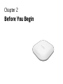
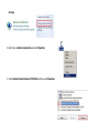
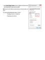
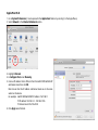
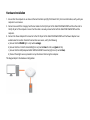
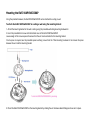
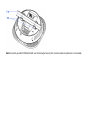
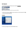
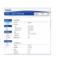
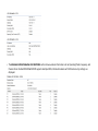
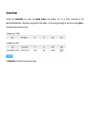
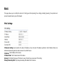
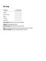
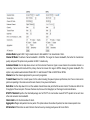
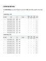
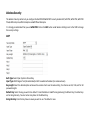
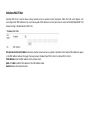
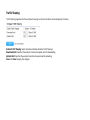
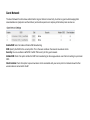
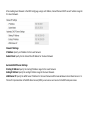
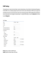
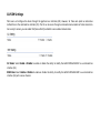
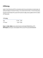
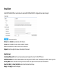
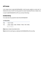
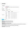
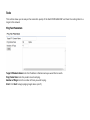
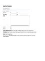
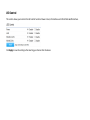
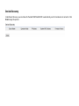
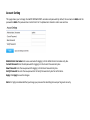
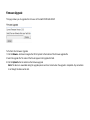
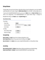
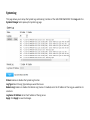
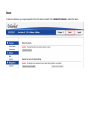
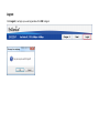
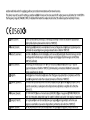
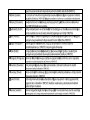
Table of Contents Chapter 1 ........................................................................................................................................................................................ 5 Key Features ............................................................................................................................................................................................ 6 Introduction .............................................................................................................................................................................................. 7 System Requirements ............................................................................................................................................................................... 8 Package Contents ..................................................................................................................................................................................... 8 Applications ............................................................................................................................................................................................. 9 Technical Specifications ........................................................................................................................................................................ 10 Physical Interface ....................................................................................................................................................................................11 Chapter 2 ...................................................................................................................................................................................... 12 Considerations for Wireless Installation ................................................................................................................................................ 13 Computer Settings .................................................................................................................................................................................. 14 Hardware Installation ............................................................................................................................................................................. 18 Mounting the EWS310AP/EWS320AP ................................................................................................................................................. 19 Chapter 3 ...................................................................................................................................................................................... 22 Default Settings ...................................................................................................................................................................................... 23 Web Configuration ................................................................................................................................................................................. 24 Chapter 4 ...................................................................................................................................................................................... 26 Device Status .......................................................................................................................................................................................... 27 Connections ............................................................................................................................................................................................ 30 Chapter 5 ...................................................................................................................................................................................... 31 IPv4 Settings .......................................................................................................................................................................................... 32 IPv6 Settings .......................................................................................................................................................................................... 33 Spanning Tree Settings........................................................................................................................................................................... 34 Chapter 6 ...................................................................................................................................................................................... 35 Wireless Settings .................................................................................................................................................................................... 36 2.4GHz/5GHz SSID Profile ................................................................................................................................................................... 38 Wireless Security ................................................................................................................................................................................... 40 Wireless MAC Filter .............................................................................................................................................................................. 43 Traffic Shaping ....................................................................................................................................................................................... 44 Guest Network ....................................................................................................................................................................................... 45 Fast Handover ........................................................................................................................................................................................ 47 Management VLAN Settings ................................................................................................................................................................. 48 Chapter 7 ...................................................................................................................................................................................... 49 SNMP Settings ....................................................................................................................................................................................... 50 CLI/SSH Settings ................................................................................................................................................................................... 52 HTTPS Settings...................................................................................................................................................................................... 53 Email Alert ............................................................................................................................................................................................. 54 Date and Time Settings .......................................................................................................................................................................... 55 WiFi Scheduler....................................................................................................................................................................................... 56 Tools ....................................................................................................................................................................................................... 58 LED Control ........................................................................................................................................................................................... 61 Device Discovery ................................................................................................................................................................................... 62 Chapter 8 ...................................................................................................................................................................................... 63 Account Setting ...................................................................................................................................................................................... 64 Firmware Upgrade ................................................................................................................................................................................. 65 Backup/Restore ...................................................................................................................................................................................... 66 System Log ............................................................................................................................................................................................ 67 Reset ....................................................................................................................................................................................................... 68 Logout .................................................................................................................................................................................................... 69 Appendix ...................................................................................................................................................................................... 70 Appendix A - FCC Interference Statement ............................................................................................................................................ 71 Appendix B - IC Interference Statement ................................................................................................................................................ 72 Appendix C - CE Interference Statement............................................................................................................................................... 74 Chapter 1 Product Overview Introduction Key Features Up to 28 dBm transmit power, enabling long range connectivity Supports IEEE802.11a/b/g/n wireless standards with up to 450 Mbps / 300Mbps*1 data rate on each band Six/Four*2 internal 5dBi Omni-Directional MIMO antennas Can be used with included power adapter or via PoE with PoE 802.3at - capable Switches or Injectors Dual Band/Three Stream and Two Stream*2 Band Steering shifts dual band clients to 5 GHz for better throughput performance Secured Guest Network Note: 1. EWS310AP supports 300Mbps; EWS320AP supports 450Mbps. 2. EWS310AP has four antennas; EWS320AP has six antennas. Introduction The EWS310AP/EWS320AP is an enhanced -powered, long-range, Dual-band concurrent Wireless 802.11a/b/g/n Access Point. It is designed to operate in numerous environments; from large homes, small and medium-sized businesses, multiple-floor offices, hotels, and other venues, to larger enterprise deployments. Its enhanced-powered, long-range characteristics make it a cost-effective alternative to ordinary Access Points that don’t have the range and reach to connect to a growing number of wireless users who wish to connect to a large hotspot or business network. The EWS310AP/EWS320AP supports the 2.4 GHz frequency band under the 802.11b/g/n mode while at the same time providing a 5 GHz band for communicating or transferring files in a less congested network frequency band. The EWS310AP/EWS320AP also delivers up to 6x faster wireless speeds compared to legacy 802.11a/b/g wireless devices. Even though the EWS310AP/EWS320AP has been designed and engineered for heavy traffic and demanding business environments, in larger housing environments as it can efficiently extend the wireless range of an existing home router. This makes it especially ideal in architecturally-challenging structures, providing whole home connectivity. To protect sensitive data during wireless transmissions, the EWS310AP/EWS320AP offers different encryption settings for wireless transmissions, including industry standard WPA and WPA2 encryption. The EWS310AP/EWS320AP also includes MAC address filtering to allow network administrators to offer network access only to known computers and other devices based on their MAC addresses. System Requirements The following are the Minimum System Requirements in order to configure the device: Computer with an Ethernet interface or wireless network capability Windows OS (XP, Vista, 7, 8), Mac OS, or Linux-based operating systems Web-Browsing Application (i.e. : Internet Explorer, Firefox, Chrome, Safari, or another similar browser application) Package Contents The EWS310AP/EWS320AP package contains the following items (all items must be in package to issue a refund): EWS310AP or EWS320AP Access Point Power Adapter RJ-45 Ethernet Cable Quick Installation Guide Ceiling and Wall Mount Screw kit Applications Wireless LAN (WLAN) products are easy to install and highly efficient. The following list describes some of the many applications made possible through the power and flexibility of WLANs: Difficult-to-Wire Environments: There are many situations where wires cannot be installed, deployed easily, or cannot be hidden from view. Older buildings, sites with multiple buildings, and/or areas that make the installation of a Ethernet-based LAN impossible, impractical or expensive are sites where WLAN can be a network solution. Temporary Workgroups: Create temporary workgroups/networks in more open areas within a building; auditoriums, amphitheaters classrooms, ballrooms, arenas, exhibition centers, or temporary offices where one wants either a permanent or temporary Wireless LAN established. The Ability to Access Real-Time Information: Doctors/Nurses, Point-of-Sale Employees, and/or Warehouse Workers can access real-time information while dealing with patients, serving customers, and/or processing information. Frequently Changing Environments: Set up networks in environments that change frequently (i.e.: Show Rooms, Exhibits, etc.). Small Office and Home Office (SOHO) Networks: SOHO users require a cost-effective, easy, and quick installation of a small network. Training/Educational Facilities: Training sites at corporations or students at universities use wireless connectivity to exchange information between peers and easily access information for learning purposes. Technical Specifications Standard Power Requirements IEEE802.11b/g/n on 2.4GHz IEEE802.11a/n on 5GHz IEEE802.3at External Power Adapter DC IN, 12V/2A Antenna Security * Four/Six Internal 5 dBi Omni-Directional Antennas Note: EWS310AP has four antennas; EWS320AP has six antennas. WEP (64/128bit) WPA/WPA2(TKIP/AES) Hidden ESSID MAC address filtering, up to 50 fields L2 Isolation 802.1X Authenticator (MD5/TLS/TTLS/PEAP) Guest Network Physical Interface QoS (Quality of Service) 1 x 10/100/1000 Gigabit Ethernet Port 1 x Reset Button 1 x Power Connector WMM (Wireless Multimedia) LED Indicator Physical/Environment Conditions Power Operating: WLAN (Wireless Connection) LAN Mesh Temperature: 32 oF to 104 oF (-0oC to 40oC) Humidity (Non-condensing): 90% or less Storage: Temperature: -4oF to 140oF (-20oC to 60oC) Humidity (Non-condensing): 90% or less Physical Interface Dimensions and Weights Diameter: 6.36” Height: 2.17” 1. Reset Button: Press and hold for over 10 seconds to reset to factory default settings. 2. LED Indicators: LED lights for Mesh, WLAN 5GHz, WLAN 2.4GHz, Ethernet port, and Power 3. LAN Port (802.3at PoE): Ethernet port for RJ-45 cable. 4. Power Connector: 12V DC IN for Power. 5. Ceiling (Wall) Mount Hole: Using the provided hardware, the EWS310AP/EWS320AP can be attached to a ceiling or wall. 6. Kensington Security Slot: To protect your EWS310AP/EWS320AP, use the Kensington Security Slot to attach a cable lock. Chapter 2 Before You Begin Before You Begin This section will guide you through the installation process. Placement of the EnGenius EWS310AP/EWS320AP essential to maximize the Access Point’s performance. Avoid placing the EWS310AP/EWS320AP in an enclosed space such as a closet, cabinet, or stairwell. Considerations for Wireless Installation The operating distance of all wireless devices can often not be pre-determined due to a number of unknown obstacles in the environment in which the device is deployed. Obstacles such as the number, thickness, and location of walls, ceilings, or other objects that the EWS310AP/EWS320AP’s wireless signals must pass through can weaken the signal. Here are some key guidelines for allowing the EWS310AP/EWS320AP to have an optimal wireless range during setup. Keep the number of walls and/or ceilings between the EWS310AP/EWS320AP and other network devices to a minimum. Each wall and/or ceiling can reduce the signal strength, resulting in a lower overall signal strength. Building materials make a difference. A solid metal door and/or aluminum stubs may have a significant negative effect on the signal strength of the EWS310AP/EWS320AP. Locate your wireless devices carefully so the signal can pass through drywall and/or open doorways. Materials such as glass, steel, metal, concrete, water (example: fish tanks), mirrors, file cabinets, and/or brick can also diminish wireless signal strength. Interference from your other electrical devices and/or appliances that generate RF noise can also diminish the EWS310AP/EWS320AP’s signal strength. The most common types of devices are microwaves or cordless phones. Computer Settings Windows XP/Windows 7 In order to use the EWS310AP/EWS320AP, you must first configure the TCP/IPv4 connection of your Windows OS computer system. 1. Click the Start button and open the Control Panel. Windows XP Windows 7 2a. In Windows XP, click on Network Connections. 2b. In Windows 7, click View network status and tasks in the Network and Internet section, then select Change adapter settings. 3. Right click on Local Area Connection and select Properties. 4. Select Internet Protocol Version 4 (TCP/IPv4) and then select Properties. 5. Select Use the following IP address and enter an IP address that is different from the EWS310AP/EWS320AP and Subnet mask, then click OK. Note: Ensure that the IP address and Subnet mask are on the same subnet as the device. For example: EWS310AP/EWS320AP IP address: 192.168.1.1 PC IP address: 192.168.1.2 – 192.168.1.255 PC Subnet mask: 255.255.255.0 Apple Mac OS X 1. Go to System Preferences (it can be opened in the Applications folder or by electing it in the Apple Menu). 2. Select Network in the Internet & Network section. 3. Highlight Ethernet. 4. In Configure IPv4, select Manually. 5. Enter an IP address that is different from the EWS310AP/EWS320AP and Subnet mask, then click OK. Note: Ensure that the IP address and Subnet mask are on the same subnet as the device. For example: EWS310AP/EWS320AP IP address: 192.168.1.1 PC IP address: 192.168.1.2 – 192.168.1.255 PC Subnet mask: 255.255.255.0 6. Click Apply when finished. Hardware Installation 1. Ensure that the computer in use has an Ethernet Controller port (RJ-45 Ethernet Port). For more information, verify with your computer’s user manual. 2. Connect one end of the Category 5e Ethernet cable into the RJ-45 port of the EWS310AP/EWS320AP and the other end to the RJ-45 port of the computer. Ensure that the cable is securely connected to both the EWS310AP/EWS320AP and the computer. 3. Connect the Power Adapter DC connector to the DC-IN port of the EWS310AP/EWS320AP and the Power Adapter to an available electrical outlet. Once both connections are secure, verify the following: a) Ensure that the POWER light is on (it will be orange). b) Ensure that the 2.4 GHz/5 GHz WLAN light is on (it will be blue for 2.4G, and green for 5G). c) Ensure that the LAN (Computer/EWS310AP/EWS320AP Connection) light is on (it will be blue). d) Once all three lights are on, proceed to set up the Access Point using the computer. This diagram depicts the hardware configuration. Mounting the EWS310AP/EWS320AP Using the provided hardware, the EWS310AP/EWS320AP can be attached to a ceiling or wall. To attach the EWS310AP/EWS320AP to a ceiling or wall using the mounting bracket: 1. Attach the mounting bracket to the wall or ceiling using the provided wall/ceiling mounting hardware kit. 2. Insert the provided short screws into the bottom cover of the EWS310AP/EWS320AP. Leave enough of the screws exposed to ensure that the unit can be attached to the mounting bracket. If extra space is required, use the provided spacers and long screws from the T-Rail mounting hardware kit to increase the space between the unit and the mounting bracket. 3. Mount the EWS310AP/EWS320AP on the mounting bracket by rotating the unit clockwise about 90 degrees to secure it in place. Attaching the EWS310AP/EWS320AP to a ceiling using the provided T-Rail connectors: 1. Attach the T-Rail connectors to the bottom cover of the EWS310AP/EWS320AP using the provided short screws. Note: Two sizes of T-Rail connectors are included in the mounting hardware kit: 15/16in (2.38cm) and 9/16in (1.43cm). If extra space is required to accommodate drop ceiling tiles, use the provided spacers and long screws. 2. Line up the connected T-Rail connectors with an appropriately sized rail and press the unit onto the rail until it snaps into place. Note: To protect your EWS310AP/EWS320AP, use the Kensington Security Slot to attach a cable lock (cable lock is not included). Chapter 3 Configuring Your Access Point Configuring Your Access Point This section will show you how to configure the device using the web-based configuration interface. Default Settings Please use your Ethernet port or wireless network adapter to connect the Access Point. IP Address 192.168.1.1 Username/Password admin/admin Web Configuration 1. Open a web browser (Internet Explorer/Firefox/Safari) and enter the IP Address http://192.168.1.1. Note: If you have changed the default LAN IP Address of the Access Point, ensure you enter the correct IP Address. 2. The default username and password are: admin. Once you have entered the correct username and password, click the Login button to open the web-based configuration page. 3. If successful, you will be logged in and see the EWS310AP/EWS320AP User Menu. Chapter 4 Overview Overview The Overview section contains the following options: • Device Status • Connections The following sections describe these options. Device Status Clicking the Device Status link under the Overview menu shows the status information about the current operating mode. The Device Information section shows general system information such as Device Name, MAC address, Current Time, Firmware Version, and Management VLAN ID The LAN Information section shows the Local Area Network settings such as the LAN IP Address, Subnet mask, Gateway, DNS Address, DHCP Client, and STP status. The Wirelesss LAN Information 2.4 GHz/5GHz section shows wireless information such as Operating Mode, Frequency, and Channel. Since the EWS310AP/EWS320AP supports multiple-SSIDs, information about each SSID and security settings are displayed. Connections Clicking the Connections link under the Device Status menu displays the list of clients associated to the EWS310AP/EWS320AP’s 2.4GHz/5GHz, along with the MAC address, TX, RX and signal strength for each client. Clicking Kick in the Block column removes this client. Click Refresh to refresh the Connection List page. Chapter 5 Network Basic This page allows you to modify the device’s IP settings and the Spanning Tree settings. Enabling Spanning Tree protocol will prevent network loops in your LAN network. IPv4 Settings IP Network Setting: Select whether the device IP address will use the static IP address specified in the IP Address field or be obtained automatically when the device connects to a DHCP server. IP Address: The IP Address of this device. IP Subnet Mask: The IP Subnet mask of this device. Gateway: The Default Gateway of this device. Leave it blank if you are unsure of this setting. Primary/Secondary DNS: The primary/secondary DNS address for this device. IPv6 Settings Link-Local Address: Check this if you want to use Link-Local Address. IP Address: The IPv6 IP Address of this device. Subnet Prefix Length: The IPv6 Subnet Prefix Length of this device. Gateway: The IPv6 Default Gateway of this device. Leave it blank if you are unsure of this setting. Primary / Secondary DNS: The primary / secondary DNS address for this device. Spanning Tree Settings Status: Enables or disables the Spanning Tree function. Hello Time: Specify Bridge Hello Time, in seconds. This value determines how often the device sends handshake packets to communicate information about the topology throughout the entire Bridged Local Area Network. Max Age: Specify Bridge Max Age, in seconds. If another bridge in the spanning tree does not send a hello packet for a long period of time, it is assumed to be inactive. Forward Delay: Specifies Bridge Forward Delay, in seconds. Forwarding Delay Time is the time spent in each of the Listening and Learning states before the Forwarding state is entered. This delay is provided so that when a new bridge comes onto a busy network, it analyzes data traffic before participating. Priority: Specify the Priority Number. A smaller number has greater priority. Save: Click Save to confirm the changes. Chapter 6 2.4GHz & 5GHz Wireless Wireless Network This page displays the current status of the Wireless settings of the EWS310AP/EWS320AP. Wireless Settings Device Name: Enter a name for the device. The name you type appears in SNMP management. This name is not the SSID and is not broadcast to other devices. Country/Region: Select a Country/Region to conform to local regulations. Band Steering: Enable Band Steering to sends 802.11n clients to the 5GHz band, where 802.11b/g clients cannot go, and leaves the 802.11b/g clients in 2.4GHz to operate at their slower rates. Band Steering works within the Access Point by directing 5GHz-capable clients to that band. *Note: In order for the Band Steering function to work properly, both the 2.4GHz and the 5GHz SSID and security settings must be under the same selection settings. Wireless Mode: Supports 802.11b/g/n mixed mode in 2.4GHz and 802.11a/n mixed mode in 5GHz. Channel HT Mode: The default channel bandwidth is 20/40MHz. The larger the channel bandwidth, the better the transmission quality and speed. This option is only available for 802.11n modes only. Extension Channel: Use the drop-down menu to set the Extension Channel as Upper or Lower channel. An extension channel is a secondary channel used to bond with the primary channel to increase this range to 40MHz allowing for greater bandwidth. This option is only available when Wireless Mode is 802.11n and Channel HT Mode is 20/40 MHz or 40MHz. Channel: Select the channel appropriate for your country’s regulation. Transmit Power: Select the transmit power for the radio. Increasing the power improves performance, but if two or more access points are operating in the same area on the same channel, it may cause interference. Data Rate: Use the drop-down list to set the available transmit data rates permitted for wireless clients. The data rate affects the throughput of the access point. The lower the data rate, the lower the throughput, but the longer transmission distance. RTS/CTS Threshold: Specifies the threshold package size for RTC/CTS. A small number causes RTS/CTS packets to be sent more often and consumes more bandwidth. Client Limits: Limits the total number of clients. Aggregation: Merges data packets into one packet. This option reduces the number of packets, but also increases packet sizes. AP Detection: AP Detection can select the best channel to use by scanning nearby areas for Access Points. 2.4GHz/5GHz SSID Profile Under Wireless Settings, you can edit the SSID profile to fit your needs. Click Edit under the SSID you would like to make changes to. Enable: Check this option to enable this profile. SSID: Specifies the SSID for the current profile. Security: Displays the Security Mode the SSID uses. You can click Edit to change the security mode. For more details, see the next section. Hidden SSID: Check this option to hide the SSID from clients. If checked, the SSID will not appear in the site survey. Client Isolation: Check this option to prevent communication between client devices. VLAN Isolation: Check this option to enable VLAN Isolation feature. VLAN ID: Specifies the VLAN ID for the SSID profile. Wireless Security The Wireless Security section lets you configure the EWS310AP/EWS320AP’s security modes: WEP, WPA-PSK, WPA2-PSK, WPA-PSK Mixed, WPA-Enterprise, WPA2-Enterprise and WPA Mixed Enterprise. It is strongly recommended that you use WPA2-PSK. Click on the Edit button under Wireless Settings next to the SSID to change the security settings. WEP Auth Type: Select Open System or Shared Key. Input Type: ASCII: Regular Text (Recommended) or HEX: Hexadecimal Numbers (For advanced users). Key Length: Select the desired option and ensure the wireless clients use the same setting. Your choices are: 64, 128, and 152-bit password lengths. Default Key: Select the key you wish to be default. Transmitted data is ALWAYS encrypted using the Default Key; the other Keys are for decryption only. You must enter a Key Value for the Default Key. Encryption Key: Enter the Key Value or values you wish to use. The default is none. WPA-PSK/WPA2-PSK (Pre-Shared Key) Encryption: Select the WPA/WPA2 encryption type you would like to use. Available options are Both, TKIP(Temporal Key Integrity Protocol) and AES(Advanced Encryption Standard). Please ensure that your wireless clients use the same settings. Passphrase: Wireless clients must use the same Key to associate the device. If using ASCII format, the Key must be from 8 to 63 characters in length. If using HEX format, the Key must be 64 HEX characters in length. Group Key Update Interval: Specify how often, in seconds, the Group Key changes. WPA/WPA2-Enterprise Encryption: Select the WPA/WPA2 encryption type you would like to use. Available options are Both, TKIP(Temporal Key Integrity Protocol) and AES(Advanced Encryption Standard). Please ensure that your wireless clients use the same settings. Group Key Update Interval: Specify how often, in seconds, the group key changes. Radius Server: Enter the IP address of the Radius server. Radius Port: Enter the port number used for connections to the Radius server. Radius Secret: Enter the secret required to connect to the Radius server. Radius Accounting: Enables or disables the accounting feature. Radius Accounting Server: Enter the IP address of the Radius accounting server. Radius Accounting Port: Enter the port number used for connections to the Radius accounting server. Radius Accounting Secret: Enter the secret required to connect to the Radius accounting server. Interim Accounting Interval: Specify how often, in seconds, the accounting data sends. Note: 802.11n does not allow WEP/WPA-PSK TKIP/WPA2-PSK TKIP security mode. The connection mode will automatically change from 802.11n to 802.11g. Wireless MAC Filter Wireless MAC Filter is used to allow or deny network access to wireless clients (computers, tablet PCs, NAS, smart phones, etc.) according to their MAC addresses. You can manually add a MAC address to restrict permission to access EWS310AP/EWS320AP. The default setting is: Disable Wireless MAC Filter. ACL (Access Control List) Mode: Determines whether network access is granted or denied to clients whose MAC addresses appear in the MAC address table on this page. Choices given are: Disabled, Deny MAC in the list, or Allow MAC in the list. MAC Address: Enter the MAC address of the wireless client. Add: Click Add to add the MAC address to the MAC Address table. Delete: Deletes the selected entries. Traffic Shaping Traffic Shaping regulates the flow of packets leaving an interface to deliver improved Quality of Service. Enable Traffic Shaping: Select to Enable or Disable Wireless Traffic Shaping. Download Limit: Specifies the wireless transmission speed used for downloading. Upload Limit: Specifies the wireless transmission speed used for uploading. Save: Click Save to apply the changes. Guest Network The Guest Network function allows administrators to grant Internet connectivity to visitors or guests while keeping other networked devices (computers and hard drives) and sensitive personal or company information private and secure. Enable SSID: Select to Enable or Disable SSID broadcasting. SSID: Specify the SSID for the current profile. This is the name visible on the network to wireless clients. Security: You can use None or WPA-PSK / WPA2-PSK security for this guest network. Hidden SSID: Check this option to hide the SSID from broadcasting to discourage wireless users from connecting to a particular SSID. Client Isolation: Check this option to prevent wireless clients associated with your access point to communicate with other wireless devices connected to the AP. After enabling Guest Network in the SSID Config page, assign an IP Address, Subnet Mask and DHCP server IP address range for this Guest Network. Manual IP Settings IP Address: Specify an IP Address for the Guest Network Subnet Mask: Specify the the Subnet Mask IP Address for the Guest Network Automatic DHCP Server Settings Starting IP Address: Specify the starting IP Address range for the Guest Network. Ending IP Address: Specify the ending IP Address range for the Guest Network. WINS Server IP: Specify the WINS Server IP Address for the Guest Network. WINS means Windows Internet Name Service. It is Microsoft's implementation of NetBIOS Name Service (NBNS), a name server and service for NetBIOS computer names. Fast Handover With Fast Handover enabled, the AP will send a disassociation request to the wireless client and let it find another AP to handover and associate upon detecting the wireless client’s RSSI value lower than specified. The RSSI value can be adjusted to allow more clients to stay associated to this AP. Note that setting the RSSI value too low may cause wireless clients to reconnect frequently. Management VLAN Settings This section allows you to assign a VLAN tag to the packets. A VLAN is a group of computers on a network whose software has been configured so that they behave as if they were on a separate Local Area Network (LAN). Computers on VLAN do not have to be physically located next to one another on the LAN. Status: If your network includes VLANs and if tagged packets need to pass through the Access Point, select Enable and enter the VLAN ID. Otherwise, click Disable. Save: Click Save to apply the changes. Note: If you reconfigure the Management VLAN ID, you may lose your connection to the EWS310AP/EWS320AP. Verify that the DHCP server supports the reconfigured VLAN ID and then reconnect to the EWS310AP/EWS320AP using the new IP address. Chapter 7 Management SNMP Settings This page allows you to assign the Contact Details, Location, Community Name, and Trap Settings for Simple Network Management Protocol (SNMP). This is a networking management protocol used to monitor network attached devices. SNMP allows messages (called protocol data units) to be sent to various parts of the network. Upon receiving these messages, SNMP compatible devices (called agents) returns the data stored in their Management Information Bases. To configure SNMP Settings, click under the Advanced tab on the side bar under Management. Status: Enables or Disables the SNMP feature. Contact: Specifies the contact details of the device. Location: Specifies the location of the device. Port: Displays the port number. Community Name (Read Only): Specifies the password for the SNMP community for read only access. Community Name (Read/Write): Specifies the password for the SNMP community with read/write access. Trap Destination Address: Specifies the port and IP address of the computer that will receive the SNMP traps. Trap Destination Community Name: Specifies the password for the SNMP trap community. SNMPv3 Status: Enables or Disables the SNMPv3 feature. User Name: Specifies the username for the SNMPv3.feature Auth Protocol: Select the Authentication Protocol type: MDS or SHA. Auth Key: Specify the Authentication Key for authentication. Priv Protocol: Select the Privacy Protocol type: DES. Priv Key: Specifies the privacy key for privacy. Engine ID: Specifies the Engine ID for SNMPv3. CLI/SSH Settings Most users will configure the device through the graphical user interface (GUI). However, for those who prefer an alternative method there is the command line interface (CLI). The CLI can be access through a command console, modem or Telnet connection. For security’s concern, you can enable SSH (Secure Shell) to establish a secure data communication. CLI Status: Select Enable or Disable to enable or disable the ability to modify the EWS310AP/EWS320AP via a command line interface (CLI). SSH Status: Select Enable or Disable to enable or disable the ability to modify the EWS310AP/EWS320AP via a command line interface (CLI) with a secure channel. HTTPS Settings Hypertext Transfer Protocol Secure (HTTPS) is a communications protocol for secure communication over a computer network, with especially wide deployment on the Internet. Technically, it is not a protocol in and of itself; rather, it is the result of simply layering the Hypertext Transfer Protocol (HTTP) on top of the SSL/TLS protocol, thus adding the security capabilities of SSL/TLS to standard HTTP communications. Status: Select Enable or Disable to enable or disable the ability to modify the EWS310AP/EWS320AP via a HTTPS. HTTPS forward: Enable this option; it will be forwarded to HTTPS if user uses HTTP to access EWS310AP/EWS320AP. Email Alert EWS310AP/EWS320AP will send email alerts when EWS310AP/EWS320AP’s configuration has been changed. Status: Check Enable to enable Email Alert feature. From: Enter the address to show as the sender of the email. To: Enter the address to show as the receiver of the email. Subject: Enter the subject to show as the subject of the email. Email Account Username/Password: Enter the username and password required to connect to the SMTP server. SMTP Server/Port: Enter the IP address/domain name and port of the SMTP server. The default port of SMTP Server is port 25. Security Mode: Select the mode of security for the Email alert. The options are None, SSL/TLS and STARTTLS. Send Test Mail: Click Send Test Mail button to test the Email Alert setup. Apply: Click Apply to save the changes. Date and Time Settings This page allows you to set the internal clock of the EWS310AP/EWS320AP. To access the Date and Time settings, click Time Zone under the Management tab on the side bar. Manually Set Date and Time: Manually specify the date and time. Synchronize with PC: Click to Synchronize the EWS310AP/EWS320AP with the computer’s internal clock. Automatically Get Date and Time: Enter the IP address of an NTP server or use the default NTP server to have the internal clock set automatically. Time Zone: Choose the time zone you would like to use from the drop-down list. Enable Daylight Savings: Check the box to enable or disable daylight savings time for the EWS310AP/EWS320AP. Next, enter the dates that correspond to the present year’s daylight savings time. Click Apply to save the changes. WiFi Scheduler Use the schedule function to reboot EWS310AP/EWS320AP or control the wireless availability on a routine basis. The Schedule function relies on the GMT time setting acquired from a network time protocol (NTP) server. For details on how to connect the EWS310AP/EWS320AP to an NTP server, see Date and Time Settings. Auto Reboot Settings You can specify how often you would like to reboot the EWS310AP/EWS320AP. Status: Enables or disables the Auto Reboot function. Timer: Specifies the time and frequency in rebooting the EWS310AP/EWS320AP by Min, Hour and Day. WiFi Scheduler Status: Enables or disables the WiFi Scheduler function. Wireless Radio: Select 2.4GHz or 5GHz to use WiFi Schedule. SSID Selection: Select a SSID to use WiFi Schedule. Schedule Templates: EWS310AP/EWS320AP provides three templates: Always available, Available 8-5 daily and Available 8-5 daily except weekends. Select Custom schedule if you want to set the schedule manually. Schedule Table: Set the schedule manually. Tools This section allows you to analyze the connection quality of the EWS310AP/EWS320AP and trace the routing table to a target in the network. Ping Test Parameters Target IP/Domain Name: Enter the IP address or Domain name you would like to search. Ping Packet Size: Enter the packet size of each ping. Number of Pings: Enter the number of times you wish to ping. Start: Click Start to begin pinging target device (via IP). Traceroute Parameters Target IP/Domain Name: Enter an IP address or domain name you wish to trace. Start: Click Start to begin the trace route operation. Stop: Halts the traceroute test. Speed Test Parameters Target IP/Domain Name: Enter an IP address or domain name you wish to run a Speed Test for. Time Period: Enter the time in seconds that you would like the test to run for and in how many intervals. Start: Starts the Speed Test. IPv4 / IPv6 Port: EWS310AP/EWS320AP uses IPv4 port 5001 and IPv6 port 5002 for the speed test. LED Control This section allows you to control the LED control functions: Power status, LAN interface and 2.4GHz/5GHz WLAN interface. Click Apply to save the settings after selecting your choices from the boxes. Device Discovery Under Device Discovery, you can choose for the EWS310AP/EWS320AP to automatically scan for local devices to connect to. Click Scan to begin the process. Chapter 8 System Manager Account Setting This page allows you to change the EWS310AP/EWS320AP username and password. By default, the username is admin and the password is admin. The password can contain from 0 to 12 alphanumeric characters and is case sensitive. Administrator Username: Enter a new username for logging in to the Administrator Username entry box. Current Password: Enter the old password for logging in to the Current Password entry box. New Password: Enter the new password for logging in to the New Password entry box. Verify Password: Re-enter the new password in the Verify Password entry box for confirmation. Apply: Click Apply to save the changes. Note: it is highly recommended that you change your password to something more unique for greater security. Firmware Upgrade This page allows you to upgrade the Firmware of the EWS310AP/EWS320AP. To Perform the Firmware Upgrade: 1. Click the Browse… button and navigate the OS File System to the location of the Firmware upgrade file. 2. Select the upgrade file. The name of the file will appear in the Upgrade File field. 3. Click the Upload button to commence the Firmware upgrade. Note: The device is unavailable during the upgrade process and must restart when the upgrade is completed. Any connections to or through the device will be lost. Backup/Restore This page allows you to save the current device configurations. When you save the configurations, you can also reload the saved configurations into the device through the Restore New Settings from a file folder. If extreme problems occur, or if you have set the EWS310AP/EWS320AP incorrectly, you can use the Reset button in the Reset to Default section to restore all the configurations of the EWS310AP/EWS320AP to the original default settings. To Configure the Backup/Restore Settings, click Firmware under the Systems Manager tab. Factory Setting Backup Setting: Click Export to save the current device configurations to a file. Restore New Setting: Choose the file you wish restore for settings and click Import. Reset to Default: Click the Reset button to restore the EWS310AP/EWS320AP to its factory default settings. User Setting Back Up Setting as Default: Click Backup to backup the user settings you would like to use as the default settings. Restore to User Default: Click Restore to restore the EWS310AP/EWS320AP to user’s default settings. System Log This page allows you to setup the System Log and local log functions of the EWS310AP/EWS320AP. Click Log under the Systems Manager tab to open up the System Log page. Status: Enables or disables the System Log function. Log Type: Select the Log Type mode you would like to use. Remote Log: Enables or disables the Remote Log feature. If enabled, enter the IP address of the Log you would like to remote to. Log Server IP Address: Enter the IP address of the log server. Apply: Click Apply to save the changes. Reset In some circumstances, you may be required to force the device to reboot. Click on Reboot the Device to reboot the device. Logout Click Logout, it will pop up a warning window. Click OK to logout. Appendix Appendix A - FCC Interference Statement Federal Communication Commission Interference Statement FCC Caution: IMPORTANT NOTE: Radiation Exposure Statement Appendix B - IC Interference Statement Industry Canada Statement Caution: Avertissement: FOR MOBILE DEVICE USAGE Radiation Exposure Statement Pour l’utilisation de dispositifs mobiles) Déclaration d’exposition aux radiations: Appendix C - CE Interference Statement Europe – EU Declaration of Conformity 0560