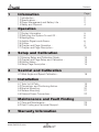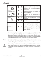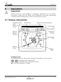
1
Analogue Display
mn100 Analogue Display
EMC Conformance
All Tacktick equipment is designed to the best industry standards for use
in the recreational marine environment. The design and manufacture of
Tacktick equipment conforms to the appropriate Electromagnetic
Compatibility (EMC) standards. Correct installation is required to ensure
that performance is not compromised.
Important
Due to the wireless communication systems used in Micronet
instruments they are only recommended for use on boats up to 18
meters (60 ft.) Before installing to a boat of aluminum or steel
construction, please contact your Tacktick dealer.
Like any other Electronic instruments your Micronet system is designed
to serve only as an aid to navigation and it remains the skippers
responsibility to maintain a permanent watch and be aware of
developing situations.
www.tacktick.com
Contents
1
2
Information
Page
1.1Introduction 1.2Specifications 1.3Power Management and Battery Life 1.4Safety and Disposal -
2
2
2
4
Operation
2.1Display Information 2.2Switching the System On and Off 2.3Backlighting 2.4Audible Signals and Alarms 2.5Utilities 2.6Chapter and Page Operation 2.7Chapter and Page Description -
3
Setup and Calibration
3.1Entering Setup and Calibration Mode 3.2Chapter and Page Setup and Calibration 3.3Editing Values 3.4Setup Page Description -
4
19
19
20
21
22
Maintenance and Fault Finding
6.1Care and Maintenance 6.2Fault Finding and Technical Support -
7
18
Installation
5.1Tools List & Parts 5.2Precautions and Positioning Advise 5.3Bracket Mounting 5.4Surface Mounting 5.5External Power Connections -
6
13
13
13
14
Seatrial and Calibration
4.1Wind Angle and Speed Calibration -
5
5
6
6
6
7
8
10
23
23
Warranty Information
www.tacktick.com
1
mn100 Analogue Display
1
Information
1.1
Introduction
Your Micronet display is powered for life by the environment. Although
feature packed and highly visible in all conditions, current demand is so
low, and the supply so efficient, that the solar-powered display is self
sufficient. Combined with other displays in the Micronet range this
display becomes part of a complete navigational system.
1.2
Specifications
Height of digits: 7mm (0.28")
Backlighting:
3 levels with daylight shutoff
System-wide or local control
Power:
Solar Powered
300 hrs autonomy by day, 7 nights at brightest backlighting,
20 nights at economy backlighting without charge
Units of display: Wind Speed (knots, meters per second, Beaufort)
Alarm:
Audible Alarm for lost network
Weight:
285g (0.63lbs)
Operating Temp.: -10o to +60oC (14o to 140oF)
Frequency:
868 MHz or 916 MHz
This unit can be controlled using the T113 Remote Display
1.3
Power Management and Battery Life
What makes your mn100 display possible is Tacktick’s revolutionary
approach to power management. By reducing the amount of power
being used by the electronics and maximizing the potential of the sun to
provide power, a mn100 display becomes a virtually perpetual device.
Power status is indicated by two icons on the display:
Battery Level
and
Charge Rate
Used together these icons will show the condition of the power supply.
2
www.tacktick.com
Introduction
Bright Sunny Day
Battery is charged and being
topped up by the sun. (see Note)
Battery is low and being charged
by the sun.
Overcast Day
Battery is charged and requires no
further charging.
Battery is low but maintaining it’s
level.
Night
Battery is charged but is not
charging.
Battery is low with no charging.
LOW Power
It is recommended that the
instrument be left in daylight for
some time for the battery to
recover, or charge from an external
9-30V power source. A fully
discharged battery will recharge in
approximately 12 hours of direct
bright sunlight.
If using the displays at night, power usage can be reduced dramatically
by switching the backlighting to level 1 or Off. If backlighting is not
required on displays located below decks it is best to set them to "Local"
backlighting control (see page 15 –s9) so that power is not being wasted
in displays which may not be visible from the one being viewed.
Note:
If the internal battery is fully charged then it does not matter how much
the display is subjected to bright sunlight no further charging is required
and the Charge Rate Indicator will remain low.
If the displays are to be stored for a long period of time before next use
(over winter) ensure that the batteries are fully charged before storage.
If necessary connect to a 9 to 30V DC power supply for 24 hrs prior to
storage.
www.tacktick.com
3
mn100 Analogue Display
Sleep Mode
If there is no boat speed or change in heading registered on the system
for a period of 12 hours your Micronet display will switch off to conserve
power. A "POWER SAVE" alarm will sound before the system switches
off. Pressing any button within 10 seconds of the alarm sounding will
allow the system to remain switched on.
Backlighting will automatically shut down/off when operated in daylight.
Artificial light WILL NOT recharge the battery. Placing your Micronet
display close to an artificial light will seriously damage the display. Only
recharge in natural daylight.
Applying External Power
In cases where displays are mounted permanently below decks it will be
necessary to apply an external power source to prevent complete
discharge of the built in battery.
Connections on the rear of the display allow a 9V to 30V DC power
source to be connected. Connections can be made to the vessels DC
system or a 9V battery pack may be connected. It is recommended that
permanent connection is only made when the displays are permanently
fixed to the vessel and not when the clip brackets are used.
Connection to a 9V (PP3) battery will fully recharge the internal battery
over a period of 24 hours.
1.4
Safety and Disposal
Your Micronet display contains Manganese Lithium Dioxide batteries
which should be disposed of correctly. Do not dispose of any instrument
in domestic waste. Refer to regulations in force in your country.
If in doubt return the instrument to Tacktick Ltd. for correct disposal.
4
www.tacktick.com
Operation
2
Operation
Important:
Ensure that the "Auto Network" procedure described on the yellow
instruction sheet and full Setup and Calibration has been performed
correctly before attempting to use your Micronet system.
2.1 Display Information
Chapter Button
Hold
down for
on/off
Set-up
Button
Prompt
Set Button
Page and Adjust Buttons
Hold down
for
Backlighting
Analogue
Pointer
Descriptive
Text
Battery
Level
Charge
Rate
Display Icons
The following icons are used to display information on the screen
KTS , M/S to display wind speed units
TRU , APP to indicate true or apparent wind
o to indicate degrees of angle
www.tacktick.com
5
mn100 Analogue Display
2.2
Switching the System On and Off
To switch your Micronet system on or off select any display and press
the
button for 2 seconds.
Switch On
2.3
Switch Off
Backlighting
At any stage of the display’s operation press and hold for 2 seconds the
button to access the lighting control.
Pressing the
and
buttons will scroll through the options:
OFF, 1, 2 and 3 whilst changing the backlighting.
Depending on the display setup (see page 15 -s9), backlighting
on the whole system or just the single display will be altered.
Backlighting is automatically switched off in daylight as part of the
display’s power saving feature and will not operate in daylight.
2.4
Audible Signals and Alarms
At stages during its operation your Micronet display will beep to indicate
alarms or moments of importance.
Power-up
Once operating as part of a network the display will issue a single
beep as it is switched on by pressing the
button for 2 second.
Button Press A single beep is issued each time a button is pressed. A second
beep is issued after a 2 second hold down of the
button.
Alarm
Continuous bursts of three beeps indicates a lost network alarm.
The alarm is indicated on the digital display. Pressing any button
will silence the alarm. See fault finding section on p23.
6
www.tacktick.com
Operation
2.5
Keylock
Utilities
The Keylock feature protects from accidental key presses and is
intended for use in high activity applications such as crewed race
yachts. If your display is mounted in a position where keys may be
pressed accidentally (eg the companionway of a race yacht), then
you can enable keylock as follows:
Press and hold
to enter set up
Press
repeatedly to reach the OPTS chapter
Press
repeatedly to reach the Key Lock page
Press
to activate keylock.
Press and hold
to exit setup.
Once keylock is activated, pressing a key causes the unit to give the
unlock key prompt. Press
followed by
to unlock the
keys (this will allow the keys to function for one minute, after which
the keys will automatically relock).
Page Hiding To hide unwanted pages and configure an instrument to your
needs:
Press and hold
to enter set up
Press
repeatedly to reach the OPTS chapter
Press
repeatedly to reach the Page Hiding page
Press
to activate page hiding for 5 minutes
Press and hold
to exit setup.
Once page hiding is activated:
Press
for 2 seconds to hide a page
A period of 5 minutes is allowed during which you can select pages
to hide.
Page Unhide To clear Page Hiding and return to all pages visible:
Press and hold
to enter set up
Press
repeatedly to reach the OPTS chapter
Press
repeatedly to reach the Pages Hidden page
The display shows the number of pages hidden
Press
briefly to unhide the pages, the display counts down
from 3
Press and hold
to exit setup.
www.tacktick.com
7
mn100 Analogue Display
2.6
Chapter and Page Operation
Information is displayed in a "Chapter and Page" format using the
button to scroll through the chapters and the
and
buttons to
move between pages.
The diagram below shows the information format.
Default Chapter Selection
8
www.tacktick.com
Operation
Pressing the
button at any time will move on to the next chapter
and on scrolling through the chapters the page last selected in that
chapter will be displayed. Both chapter and page selection will scroll
back to the first page once a cycle has been completed.
30
30
60
30
60
90
90
120
30
60
90
90
120
150
120
120
1
150
150
30
30
40
40
50
30
60
2
150
30
40
40
50
50
50
4
3
30
30
60
30
60
120
90
90
120
120
150
50
15
5
150
60
60
90
90
30
30
50
6
30
60
60
90
90
120
50
15
7
30
50
60
30
60
30
60
90
90
30
8
30
60
90
90
30
60
120
60
120
50
50
15
10
50
90
90
30
15
50
11
30
120
50
60
15
50
60
9
90
90
120
50
040_002
15
50
12
Page Selection
For a full description of each page refer to items 1 to 12 on the
following pages.
www.tacktick.com
9
mn100 Analogue Display
2.7
Chapter and Page Descriptions
360 Degree Wind Chapter
1
30
60
Apparent Wind Angle and Speed
The apparent wind angle and speed with respect to the
vessel as measured by the Wind Transmitter.
The wind angle is shown on a 360 degree scale.
30
60
90
90
120
120
150
2
30
60
150
True Wind Angle and Speed
The true wind angle with respect to the vessel and the true
wind speed calculated by the display taking into account the
vessels speed through the water. Apparent wind speed,
angle and boat speed must be available for this calculation.
The wind angle is shown on a 360 degree scale.
30
60
90
90
120
120
150
150
Magnified Wind Chapter
3
30
40
Magnified Apparent Wind Angle and Apparent Wind Speed
The apparent wind angle and speed with respect to the
vessel as measured by the Wind Transmitter.
The wind angle is displayed on a 26 to 60 degree scale.
Downwind, the same scale is used to show the wind angle
measured from the aft of the boat. The pointer will flash when
outside of the 26-58 degree upwind/downwind range.
30
40
50
50
4
30
40
Magnified True Wind Angle and True Wind Speed
The true wind angle with respect to the vessel and the true
wind speed calculated by the display taking into account the
vessels speed through the water. Apparent wind speed,
angle and boat speed must be available for this calculation
The wind angle is displayed on a 26 to 60 degree scale.
Downwind, the same scale is used to show the wind angle measured
from the aft of the boat. The pointer will flash when outside of the 26-58
degree upwind/downwind range.
30
40
50
50
VMG Chapter
5
30
60
90
120
VMG - Velocity Made Good to Windward and True Wind Angle
True wind angle (see above) is displayed on a 360 degree
scale.
The vessels speed directly upwind is shown in the text
display. This value is calculated by the display from the boat
speed and true wind angle.
60
90
120
150
10
30
150
www.tacktick.com
Operation
6
Turn
The pointer shows the direction of the target waypoint
relative to the bow of the boat.
The display shows the distance to the waypoint. The
distance is displayed in the currently selected system
distance units (default Nautical Miles).
Warning: the Turn page uses GPS COG and BTW and therefore takes
tide and set into account. With the pointer dead ahead, your course is
directly to the waypoint, but you may not be pointing at the waypoint.
30
60
30
60
90
90
120
50
15
50
Beaufort Chapter
7
Beaufort Wind Speed and Direction
The true wind speed and direction over the ground are
displayed using the Beaufort scale, calculated by the display
taking into account the vessels speed through the water and
compass heading.
Apparent wind speed, angle, boat speed and current
heading must be available for this calculation.
8
30
60
Beaufort Wind Speed and wind speed in knots
The windspeed over the ground is displayed in the Beaufort
scale and in knots.
30
60
90
90
120
50
15
50
Heading Chapter
Note:
Heading values will be displayed as either magnetic or true depending
on the the system compass setting.
The heading value displayed will also be affected by the calibration
routine for the compass.
The system compass setting and calibration can only be changed by a
Digital or Dual Digital Display.
9
Heading.
30
30
60
60
90
90
The current compass heading of the vessel as measured by
the Compass Transducer.
The pointer indicates the direction of North.
120
50
15
50
www.tacktick.com
11
mn100 Analogue Display
10
Tack
30
30
60
60
90
90
120
50
15
11
The compass heading that the vessel will follow should it
tack through the wind, calculated by the display. Apparent
wind angle and magnetic heading must be available for this
calculation to be made.
50
COG
30
30
60
60
90
90
The vessel’s course over the ground as calculated by the
GPS Antenna.
The pointer points to the direction of North.
120
50
15
12
Locked heading
To help a helmsman steer to a target heading, press the
button from the heading page to lock onto the current
heading. The display will show the target heading in degrees
and this can be increased or decreased with the
and
buttons. The heading deviation from target is shown as
a fan, the larger the fan the further off course.
To return to the heading page, press the
button
30
60
50
30
60
90
90
120
50
15
12
50
www.tacktick.com
Set-up and Calibration
3
Setup and Calibration
3.1
Entering Setup and Calibration Mode
To enter the Setup and Calibration Menu press and hold for 2 seconds
the
button.
3.2
Chapter and Page Setup and Calibration
Setup and calibration functions are displayed in a "Chapter and Page"
format using the
button to scroll through the chapters and the
and
buttons to move between pages. The diagram below shows
the information format.
Chapters
Pages
UNIT
KTS
M/S
S1
WIND
RESP
AUT SLO
NOr Fst
O
<value>
<actual>
S2
OPTS
<value>%
<actual>
S3
S4
AUTO
LOCK
HIDE
nEt
OFF
ON
OFF
ON
S6
S5
HIDN
LITE
0
<value>
S7
V<version>
NO<nodes>
S14
OFF
ON
S9
S8
S10
RSET
TyPE
LCD
NO
Ptr
<value>
S12
S13
HLTH
SHOW
nEt
LOC
S11
HULL
WIND
NMEA
MAST
MOB
-----
-----
-----
-----
-----
S15
S16
S17
S19
S18
TyP9
TyP6
-----
-----
S20
Note:
Unlike normal operation you must scroll to the chapter heading page
before moving to another chapter.
3.3
Editing Values
To adjust any settings press the
button. The setting will start to flash
and the
and
buttons will change the value. Then press the
button again to save the new setting.
www.tacktick.com
13
mn100 Analogue Display
3.4
Setup Page Description
UNIT - Units Chapter
Press the
button quickly to edit, press the
or
to change
units and press the
button quickly to select the chosen units.
Default values are indicated in bold.
s1
Wind Speed
Sets the units in which all Wind Speed related information is
displayed. KTS (Knots) or M/S (meters per second).
WIND - Wind Chapter
Press the
button quickly to edit, press the
or
to change
units and press the
button quickly to select the chosen units.
Default values are shown in bold.
s2
Response
Sets the update period of the Wind display.
AUt (Auto) / SLO (Slow) / nOr (Normal) / FSt (Fast)
s3
Wind Angle
Aligns the displayed apparent wind angle with the actual
wind direction with respect to the boat. See page 18 for
calibration.
s4
Wind Speed
Adds a percentage factor which corrects the information from
the Wind Transmitter and ensures the Apparent Wind Speed
is displayed correctly. See page 18 for calibration.
14
www.tacktick.com
Set-up and Calibration
OPTS - Options Chapter
Press the
button quickly to toggle the values between settings or
press the
button quickly to edit, press the
or
to change
values and press the
button quickly to select the chosen value.
Default values are shown in bold.
s5
Auto Networking
Only available on the display which was used to power up
the system.
Refer to the "Auto Network" sheet for further information.
s6
Key Lock
Enables or disables the keylock function. See page 7,
section 2.5.
s7
Page Hiding
Permits the hiding of unwanted pages.
See page 7, section 2.5.
s8
Pages Hidden / Unhide Pages
Shows the number of pages currently hidden and permits
clearing of the page hiding function
See page 7, section 2.5.
s9
Light
Tells the display to control the system Backlighting or just its
own Backlighting. nEt (network ) / LOC (local).
www.tacktick.com
15
mn100 Analogue Display
s10
Boat Show
Allows the display of information when NOT installed as part
of a Micronet system for demonstration purposes only.
Off / On.
s11
LCD Contrast
Adjusts the viewing angle and contrast of the LCD display to
improve visibility under varied mounting possibilities.
Optional values 1 - 7, default 4.
s12
Pointer Type
Toggles the width of the pointer.
If the viewing position is more than 1 metre away from the
analogue display, then the viewability can be improved by
selecting the wider pointer type.
s13
Factory Reset
Returns all the calibration settings to the factory default
values.
HLTH - Health Chapter
s14
Software Version / Network Nodes
Shows the display’s software version, battery level and
charge rate to assist in troubleshooting and fault finding.
If the display is the "Master" (the one used to switch on the
system) then the number of items (nodes) in the system will
be shown.
If the display is a "Slave" (was switched on by the system) then the signal
strength to the "Master" will be shown.
s15
Hull Transmitter Signal Strength
Shows the software version (before the decimal point), signal
strength (after the decimal point) and battery condition (level
and charge rate) of the Hull Transmitter to assist in trouble
shooting and fault finding.
16
www.tacktick.com
Title
s16
Wind Transmitter Signal Strength
As above but for Wind Transmitter information.
s17
Wireless (NMEA) Interface Signal Strength
As above but for Wireless (NMEA) Interface information.
s18
Mast Angle Sensor Signal Strength
As above but for Mast Angle Sensor information.
S19
MOB Sensor Signal Strength
As above but for MOB sensor information.
S20 -
Type 6 to Type 9
reserved for future use.
www.tacktick.com
17
mn100 Analogue Display
4
Seatrial and Calibration
Once the Micronet system has been Autonetworked and installation on
the vessel has been completed it is necessary to carry out calibration.
It is not safe to use the displays for navigational purposes until
calibration has been carried out correctly.
4.1
Wind Calibration
Both wind speed and direction can be calibrated to ensure that readings
from the Wind Transmitter are displayed accurately.
Wind Angle Offset
Motor the vessel directly into the wind.
Press and hold the
button for 2 seconds to enter Setup
Press the
button repeatedly to scroll to the WIND chapter
Press
button to move to the Wind Angle Offset page
Press the
button to enter Edit Mode
Press the
and
buttons to change the displayed value
to 000.
The upper digits will indicate the number of degrees of offset entered.
Press the
button to exit Edit Mode
Press and hold the
button to exit Setup.
Wind Speed Correction
Note:
Wind speed reading is factory calibrated to display correctly and should
not be altered unless external factors are thought to be causing incorrect
readings. Correction should only be carried out if a known correct
windspeed is available.
Press and hold the
button for 2 seconds to enter Setup
Press the
button repeatedly to scroll to the WIND chapter
Press the
button to advance to the page
Press the
button to enter Edit Mode
Press the
and
buttons to change the displayed value
to the required percentage.
The lower digits will indicate the displayed wind speed.
Press the
button to exit Edit Mode
Press and hold the
button to exit Setup.
18
www.tacktick.com
Installation
5
Installation
5.1
Tools list and Parts
Tools Required 2.5mm or 5mm Drill Bit (7mm if power connection required)
Power Drill
Cross Head Screwdriver
Parts List
5.2
Mounting Template
Display Backplate and 2x Clip Brackets
Mounting Screws (3)
Mounting Bolts (3)
M4 Studs & Thumbnuts (3)
Sealing Gaskets (4)
Double Sided Tape
Precautions and Positioning Advice
Ensure mounting surface is flat.
Leave space between displays for sun covers.
Leave space to remove display from bracket (if used).
Avoid areas where damage may occur (winch handles, feet, warps etc.)
Select a flat, smooth, surface for mounting and use the template
provided to select a suitable position for mounting your Micronet display.
Check for clarity of vision and ease of access to the control buttons, it is
recommended that displays are positioned such that your arm does
NOT pass through the spokes of the steering wheel when operating the
buttons.
Contrast is limited at night when a display is viewed from
beneath. Avoid mounting displays in a position where you will
look upwards to view them.
www.tacktick.com
19
mn100 Analogue Display
5.3
Bracket Mounting (Preferred Method)
This method allows for the easy removal of a display as and when
required, for either security reasons or to prevent damage or discomfort
whilst not in use.
1. Using the three supplied M4 bolts attach the back plate to the rear of
the display (Fig.1).
2. Drill three 2.5mm holes marked "A" on the Template and using the
supplied self tapping screws, screw the clip bracket to the mounting
surface (Fig.2).
3. Place the display flat against the bracket slightly higher than the final
position and slide gently down into position. There will be a small
click as the bracket secures the display into position (Fig.3).
4. To release the display press lightly on the bracket tab and slide the
display upwards (Fig.4).
20
www.tacktick.com
Installation
5.4
Surface Mounting
Where there is no access to the rear of the mounting surface
Easy installation but will allow removal without gaining access to the
boat. Position the supplied Template carefully before starting.
1. Drill three 2.5mm holes marked "B" on the template.
2. Carefully snap the facia of the display off the main body taking care
not to drop the button pads.
HINT – It may be useful to place a piece of sticky tape across the
front of the buttons before removing the facia to prevent them from
falling out during the installation.
3. Remove the three captive M4 nuts from the plastic moulding and
attach the display to the mounting surface using the three self
tapping screws provided. Take care not to over tighten the screws as
this may cause the moulding to crack.
4. Check the display is perfectly level; carefully position the button
inserts into the correct slots and snap the facia back into position.
Temporary Mounting
1. Use the double sided tape provided to secure the display to a
suitable mounting surface. Press the display firmly against the
surface until secure.
Note:
This method is recommended for temporary use only. For example,
finding an appropriate location before drilling holes.
www.tacktick.com
21
mn100 Analogue Display
Where access is available to the rear of the mounting surface
This method allows for maximum security of a permanently mounted
display. Position the supplied template carefully before starting.
1. Drill three 5mm holes marked "B" on the template.
2. Screw the four M4 brass studs into the rear of the display.
3. Place the display in position pushing the three studs through the
newly drilled holes.
4. Using the three supplied thumb nuts, secure the display to the
surface making sure it is level before final tightening.
5.5
External Power Connections
To connect an external 9 to 30V DC power supply to the display head
from either a portable battery or the vessel’s existing power system.
1. Drill two 7mm holes marked "P" on the mounting template and
smooth them together with a sharp knife or small file.
2. Pass the supply cable through the new hole and attach the supplied
crimp spade receptacles.
3. Remove the blanking plug from the rear of the display to expose the
terminals.
3. Taking care to connect the correct polarity push the receptacles
firmly onto the spades on the rear of the display.
4. Mount the display head securely in position.
5. Clamp the cable securely close to the display.
22
www.tacktick.com
Maintenance and Fault Finding
6
Maintenance and Fault Finding
6.1
Care and Maintenance
All Micronet products are totally sealed against water and are not
serviceable. Any attempt to take a Micronet product apart will invalidate
the warranty.
To clean, use only a damp, soft cloth. No detergents, solvents or
abrasives should be used. To avoid damaging a Micronet display unit
we recommend storing in the supplied soft pack when not in use.
If the displays are to be stored for a long period of time before next use
(Over Winter) ensure that the batteries are fully charged before storage.
If necessary connect to a 9 to 30V DC power supply for 24 hrs prior to
storage.
6.2
Fault Finding and Technical Support
A single display flashes the battery symbol and then switches off.
The battery level is low on the particular display affected. Connect to a
9 to 30V DC power source or leave in bright sunlight for 12 hours
minimum to fully recharge the display’s internal battery. If the particular
display is the system master* then the other displays will sound the Lost
Network Alarm. To continue using the rest of the system power down
and restart the system from another display.
Data is shown as dashes.
The information is not being transmitted to the displays. There may be
lost communication between the Wind Transmitter or Hull transmitter
and the displays. On any Digital display enter setup and calibration
mode (page 13) and scroll through to the Health Chapter. Check the
signal levels of the Hull and Wind Transmitters.
Wind speed reads 0.
Information being transmitted from the Wind Transmitter is being
received with a Zero value. If the anemometer cups at the top of the
mast are turning and the Wind Speed reads 0 then there is a problem
with your Wind Transmitter.
www.tacktick.com
23
mn100 Analogue Display
No NMEA data showing on external displays.
From any display enter setup and calibration mode (page 13) and scroll
through to the Health chapter. Check the signal level and battery status
of the Wireless (NMEA) Interface box.
Lost Network Alarm Sounds
Indicates that the display has lost communication with the
master. Either there is a problem with the master* or the
display has been moved out of effective range. The display
will power down shortly after sounding the alarm in order to
conserve power.
Note: * The "Master Instrument" is the display which was used to power up the
entire system. This display may be different each time the system is
used. If you are fault finding and are uncertain which display is the
master the switch off the system and switch on again. The display which
you switched on is now the master.
24
www.tacktick.com
Maintenance and Fault Finding
7
Warranty Information
General
All Tacktick products are designed and built to standards suitable for
use in a harsh marine environment. If the products are installed correctly
and operated as described in the user guides they will provide long and
reliable service. For information and assistance Tacktick operates a
network of international distributors.
Limited Warranty
The warranty covers repair or replacement of parts due to faulty
manufacturing and includes labor charges. The warranty period is two
years from the date of purchase. Tacktick specifically exclude the
implied warranty of merchantability and fitness for a particular purpose.
Conditions
• A receipt with proof of purchase date must be shown to validate any
warranty claim.
• The warranty is extended only to the original purchaser and is non
transferable.
• Products that have been incorrectly installed or have serial numbers
removed will not be covered.
• No compensation is payable for consequential damage caused
directly or indirectly by any malfunction of Tacktick products.
• Tacktick is not liable for any personal damage caused as a
consequence of using its equipment.
• Tacktick, its distributors or dealers are not liable for charges arising
from sea trials, installation surveys or visits to the boat to attend to
the product whether under warranty or not.
• Tacktick reserves the right to replace any products deemed faulty,
within the warranty period, with the nearest equivalent.
• The terms and conditions of this warranty do not affect your statutory
rights.
Claims Procedure
Product should be returned to the national distributor, or one of its
appointed dealers, in the country where it was originally purchased.
Valid claims will then be serviced and returned to the sender free of
charge. Distributors reserve the right to charge for exceptional or
express carriage if requested.
www.tacktick.com
25
mn100 Analogue Display
Alternatively, if the product is being used away from the country of
purchase, it may be returned to the national distributor, or one of its
approved dealers, in the country where it is being used. In this case valid
claims will cover parts only. labor, handling costs and return shipping will
be invoiced to the sender.
Disclaimer
Tacktick products should only be considered an aid to navigation and
common sense must be applied at all time when navigating at sea.
Tacktick reserves the right to change product specification without
notice to comply with its policy of continuous improvement.
This device complies with Part 15 of the FCC rules. Operation
is subject to the following two conditions. (1) This device may
not cause harmful interference, and (2) this device must
accept any interference received, including interference’s that
may cause undesirable operation.
Tacktick Ltd hereby declare that the mn100 Analogue Display
is in compliance with the essential requirements and other
relevant provisions of Directive 1999/5/EC.
* UU040 - GB - r ev 09 1052972*
26
www.tacktick.com