1
UPS OPERATING INSTRUCTIONS
PROTECT 1. M
PROTECT 1.040
Thank you for deciding to purchase the PROTECT 1.M
UPS from AEG Power Solutions. The following safety
instructions are an important part of the operating
instructions are will protect you against problems from
operating errors and possible dangers. Please read these
instructions carefully prior to commissioning!
2
1
Notes on these Operating
Instructions
Duty to provide information
These operating instructions help you to install and operate the
Uninterruptible Power Supply (UPS) PROTECT 1.M as well as
its USV modules PROTECT 1.040 and associated external
battery units PROTECT 1.M BP (referred to below jointly as
PROTECT 1.M) in accordance with its designated use, safely
and correctly. These operating instructions contain important
information for avoiding dangers.
Please read these instructions carefully prior to
commissioning!
These operating instructions are an integral part of
PROTECT 1.M.
The operator of this unit is obliged to communicate these
operating instructions to all personnel transporting or starting
up PROTECT 1.M or performing maintenance or any other
work on the unit.
Validity
These operating instructions comply with the current technical
specifications of PROTECT 1.M at the time of publication. The
contents do not constitute a subject matter of the contract, but
serve for information purposes only.
Warranty and liability
We reserve the right to alter any specifications given in these
operating instructions, especially with regard to technical data
and operation.
Claims in connection with supplied goods must be submitted
within one week of receipt, along with the packing slip.
Subsequent claims cannot be considered.
The warranty does not apply for damage caused by noncompliance with these instructions (such damage also includes
damage to the warranty seal). AEG will accept no liability for
consequential damage. AEG will rescind all obligations such as
3
warranty agreements, service contracts, etc. entered into by
AEG or its representatives without prior notice in the event of
maintenance and repair work being carried out with anything
other than original AEG parts or spare parts purchased
from AEG.
Handling
PROTECT 1.M is designed and constructed so that all
necessary steps for start-up and operation can be performed
without any internal manipulation of the unit. Maintenance and
repair work may only be performed by trained and qualified
personnel.
Illustrations are provided to clarify and facilitate certain steps.
If danger to personnel and the unit cannot be ruled out in the
case of certain work, it is highlighted accordingly by
pictographs explained in the safety regulations of chapter 3.
Hotline
If you still have questions after having read these operating
instructions, please contact your dealer or our "Hotline":
Tel:
+49 (0)180 5 234 787
Fax:
+49 (0)180 5 234 789
Internet: www.AEGpartnerNet.com
Copyright
No part of these operating instructions may be transmitted or
reproduced by any electronic or mechanical means without the
express prior written permission of AEG.
© Copyright AEG 2009. All rights reserved.
4
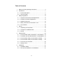
Table of Contents
1
Notes on these Operating Instructions.............................3
2
Introduction.......................................................................7
3
4
5
6
2.1
Product description.....................................................7
2.2
Technical Data..........................................................10
Safety Regulations .........................................................14
3.1
Important Instructions and Explanations ..................14
3.2
Accident Prevention Regulations .............................14
3.3
Qualified Personnel ..................................................15
3.4
Safety Instructions for PROTECT 1.M .....................15
3.5
CE certificate ............................................................18
Set-up .............................................................................18
4.1
Unpacking and Inspection ........................................19
4.2
Transport to Installation Site.....................................21
4.3
Set-Up ......................................................................22
External View .................................................................23
5.1
Front and Rear View of PROTECT 1.M (chassis)....23
5.2
Front/Rear and 3D View PROTECT 1.040 (module)... 24
5.3
Front and Rear View (communication module)........24
5.3
Front and Rear View (communication module)........25
5.4
Front View of LCD Panel ..........................................25
5.5
Display Panel............................................................26
Installation ......................................................................27
6.1
Installation Notes ......................................................27
6.2
Set-up and Installation of the Modules .....................31
5
8
7
Adding/Removing Modules ......................................33
7.1
Active Redundancy ..................................................33
7.2
Installing and Removing UPS Modules....................33
7.2.1
Basic procedure
for installing a PROTECT 1.040 UPS module...34
7.2.2
Basic procedure
for removing a PROTECT 1.040 UPS module ..34
Operating and Maintenance...........................................35
8.1
9
Operation..................................................................35
8.1.1
Start-up ..............................................................37
8.1.2
Shutting down ....................................................37
8.1.3
Inquiries .............................................................38
8.1.4
Setup..................................................................39
8.2
Maintenance.............................................................41
8.3
Shutdown and UPS Management Software.............42
Communication Interfaces .............................................43
10 Troubleshooting and Fault Rectification.........................44
11 Reference Table for the Display and UPS Operating .....45
11.1 Normal operation......................................................45
11.2 Battery Operation .....................................................45
11.3 Bypass Operation.....................................................45
11.4 Warning Signal if Battery System Not Connected....46
11.5 Warning Signal
for Phase Loss or Phase Sequence Error................46
11.6 Overload Protection..................................................47
12 Minimum Number of Battery Packs ...............................48
13 List of terms....................................................................51
13.1 Technical terminology ..............................................51
6
2
Introduction
2.1
Product description
i
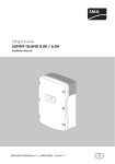
PROTECT 1.M ("M" for modular structure) is an
Uninterruptible Power Supply (UPS) for
important loads such as small data centres,
servers,
network
components,
telecommunication facilities and the like.
The PROTECT 1.M connection to the mains can be either
three or one-phase. The load connection, i.e. the UPS output,
is always one-phase. The online-/double-converter technology
guarantees the highest levels of reliability and performance.
This standard product is designed as a highly intelligent
module construction with a rack-type design. One module of
the AEG USV PROTECT 1.040 corresponds to an UPS with
full functions. Depending on the requirements for output power
and serviceability, the user can increase or reduce the number
of modules in the AEG UPS PROTECT 1.M to achieve an
optimum price/ performance ratio.
Module for UPS
communikation
& LCD display
PROTECT
1.040
UPS module 1
PROTECT
1.040
UPS module 2
PROTECT
1.040
UPS module 6
Connection
terminals
L1 L2 L3 N
+
UPS INPUT
_
Battery system
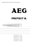
Fig.: Diagram in principle of the PROTECT 1.M
7
L
N
UPS OUTPUT
The PROTECT 1.M has been designed for operating up to six
UPS modules. Depending on the output power required, the
unit is operated in normal mode with between one and six
modules installed. These modules can easily be installed,
removed or replaced under a very wide range of operating
conditions.
PROTECT 1.M uses a high-performance communication
module to collect information from the individual UPS modules
via the internal network within the unit and displays this
information on an LC display. This greatly facilitates operation
of the UPS.
PROTECT 1.M protects your systems against numerous power
supply problems such as mains failures, voltage and frequency
fluctuations, under and overvoltage, voltage distortions, voltage
harmonics, etc.
SBS
Mains
filter
Output
PFC
Input
Filter
Inverter
Rectifier
DC/DC Booster
DSP
Control logic
Battery
charger
Battery system
(external)
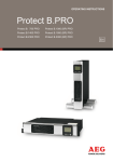
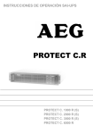
Fig.: Component diagram of an individual PROTECT 1.040 UPS module
The UPS is connected between the public utility mains and the
loads to be protected.
The power sections of the UPS module rectifier convert the
mains voltage to DC voltage for supplying the inverters. The
circuit technology used (PFC) enables sinusoidal current
consumption and therefore operation with little system
8
disturbance. Separate battery chargers configured with switch
mode power supply technology are responsible for charging or
trickle-charging the battery connected in the intermediate
circuit. The configuration of these charging rectifiers means the
harmonic content of the charging current for the battery is
almost zero, which increases the service life of the battery
even more. The inverters are responsible for converting the DC
voltage into a sinusoidal output voltage. A microprocessordriven control based on a pulse-width modulation (PWM)
integrated in each UPS module guarantees, in conjunction with
digital signal processor technology and extremely fast
pulsating IGBT power semiconductors of the inverters, a
voltage system of the highest quality and availability on the
secured busbar.
In the event of mains faults (e.g. current failures), the voltage
continues to be supplied from the inverters to the load without
any interruption. From this point onwards, the inverters draws
their power from the battery instead of the rectifiers. Since no
switching operations are necessary, there is no interruption in
the supply to the load.
The greatest possible supply reliability of connected loads is
attained by the parallel connection of up to max. six PROTECT
1.040 UPS modules. The n+x technology thus guarantees
maximum reliability through up multiple active redundancy on
the one hand as well as on the other hand the possibility of
increased power with simple redundancy or even only higher
UPS power without any redundancy.
The automatic electronic bypass serves to increase the
reliability of the supply further. It switches the public mains
directly through to the load without any interruption, e.g. when
there is a system overload. As a result, the automatic bypass
represents an extra passive redundancy for the load.
9
An integrated, manually operated bypass unit ensures an
uninterrupted supply to the connected loads in the case of
maintenance and/or service work. The internal electronic part
(with the exception of the metal-clad manual bypass) can be
disconnected via the mains input miniature circuit breakers.
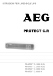
Load
Number of
UPS modules
4 kVA
1
module
2
modules
3
modules
no
redundancy
n+1
(4 kVA)
n+2
(8 kVA)
n+3
n+5
n+4
(12 kVA) (16 kVA) (20 kVA)
no
redundancy
n+1
(4 kVA)
n+2
(8 kVA)
n+3
n+4
(12 kVA) (16 kVA)
no
redundancy
n+1
(4 kVA)
n+2
(8 kVA)
n+3
(12 kVA)
no
redundancy
n+1
(4 kVA)
n+2
(8 kVA)
no
redundancy
n+1
(4 kVA)
---
no
redundancy
8 kVA
12 kVA
16 kVA
---
4
modules
-----
20 kVA
5
modules
--24 kVA
6
modules
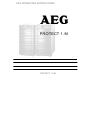
Fig.: Table showing the level of redundancy depending on the installed
modules and available output power
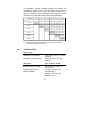
2.2
Technical Data
Type rating
PROTECT 1.M (system)
max. 24 kVA (cos ϕ = 0.7 lag.)
16800 W
PROTECT 1.040 (module)
4000 VA (cos ϕ = 0.7 lag.)
2800 W
UPS input
3ph~ or 1ph~ / N / PE
Rated connection voltage
400 V / 230 Vac (3ph~) or
230 V (1ph~)
277 Vac – 520 Vac ±3%
(Rectifier 3ph~)
160 Vac – 300 Vac ±3%
(Rectifier 1ph~)
Voltage range without
battery operation
10
176 VAC – 264 VAC ±3%
(Bypass)
Frequency
50 Hz / 60 Hz
(Automatic detection)
Frequency tolerance range
±4 Hz
Current consumption at full load (max.)
PROTECT 1.M (system)
44 A (3ph~) or 132 A (1ph~) / 155
A (Bypass)
PROTECT 1.040 (module)
7.3 A (3ph~) or 22 A (1ph~)
System disturbance factor
λ ≥ 0.98
UPS output
Nominal voltage output
Nominal frequency
Type of voltage
Crest factor
Overload behaviour
with mains supply
Overload behaviour with
battery operation
Short-circuit behaviour
220 / 230 / 240 Vac ±2%
(configuration via "CompuWatch"
software)
50 Hz / 60 Hz ±0.2 Hz (dependent
on mains frequency)
Sine, distortion
< 3% THD (linear load)
< 6% THD (non-linear load)
3:1
Up to 105% continuous;
> 105% – < 130% for 30s
130% for 2 s
Following this, automatic,
uninterrupted switchover to
integrated bypass (SBS).
Switch-off after 1 min. if overload
continues to be present (switch
back if overload decreases = load
< 90%)
Up to 105% continuous;
> 105% – < 130% for 30s
130% for 2 s
3 x IN for 100 ms
11
Battery
Nominal DC voltage (intermediate circuit) 120 Vdc
DC window 102 Vdc – 160 Vdc ±1%
Trickle charge voltage 137 Vdc ±1%
Battery charging current (max.) 3.5 Adc per UPS module
Communication
Interfaces
Shutdown software on CD
RS232 (Sub-D9)
RS485 (Sub-D9 / RJ45)
Additionally: Communication slot
for optional expansion cards (e.g.
AS/400 / SNMP, etc.)
"CompuWatch" for all common
operating systems, e.g. Windows,
Linux, Mac, Unix, FreeBSD,
Novell, Sun
General data
Classification
Total efficiency AC-AC
PROTECT 1.M (system)
PROTECT 1.040 (module)
Inherent noise (1m distance)
PROTECT 1.M (system)
PROTECT 1.040 (module)
Cooling type
Operating temperature range
Storage temperature range
Relative humidity
VFI SS 111 acc. to IEC 62040–3
double-conversion technology
> 88%
> 89%
< 62 dB(A)
< 55 dB(A)
Forced air cooling through
variable-speed fans
0 °C to +40 °C
Battery systems
(recommended):
+15°C to +25°C
0°C to +40°C
20% – 90%
12
Site altitude
Up to 1000 m at nominal output
Use more than 1000 m above sea
level results in the following
reduction in output power:
Height (m) 1000
1500
2000
2500
3000
Power
95%
90%
85%
80%
100%
Housing colour
Blackline
Weight:
PROTECT 1.M (chassis)
PROTECT 1.040 (module)
75 kg
15 kg per module
Dimensions W x H x D:
PROTECT 1.M (chassis)
PROTECT 1.040 (module)
442 mm x 965 mm x 700 mm
405 mm x 87 mm x 530 mm
Directives
The PROTECT 1.M meets the product standard EN 50091.
The CE mark on the unit confirms compliance with the EC
outline directives for 73/23 EEC – Low voltage and for 89/336
EEC – Electromagnetic compatibility if the installation
instructions described in the operating instructions are
observed.
For 73/23 EEC low-voltage directive
reference number
EN 62040-1-1 : 2003
For 89/336 EMC directive
reference number
EN 50091-2 : 1995
EN 61000-3-2 : 1995
EN 61000-3-3 : 1995
i
Warning:
This is a class A - device. This product can
generate radio interference in the domestic
environment. In this case, the user can be
required to employ additional interference
suppression measures.
13
3
Safety Regulations
3.1
Important Instructions and Explanations
The instructions for operation and maintenance as well as the
following safety regulations must be complied with to ensure
the safety of personnel as well as to ensure the continued
availability of the unit. All personnel installing/dismantling,
starting up, operating or servicing the units must be familiar
with and observe these safety regulations. Only trained and
qualified personnel may perform the work described, using
tools, equipment, test equipment and materials intended for the
purpose and in perfect working condition.
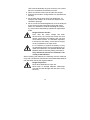
Important instructions are emphasised by the words
"Caution", "Attention", "Note" and indented text.
Caution
This symbol identifies all working and operational
procedures requiring absolute compliance to
avoid any danger to persons.
Attention
This symbol identifies all working and operational
procedures requiring absolute compliance to
prevent any damage, irreparable or otherwise, to
the unit and its components.
i
3.2
Note
This symbol identifies technical requirements and
additional information requiring the operator's
attention.
Accident Prevention Regulations
Compliance with the accident prevention regulations valid in
the respective country of use and the general safety regulations
in accordance with IEC 364 is mandatory. The following safety
rules must be observed prior to performing any work on the
PROTECT 1.M:
14
♦ Disconnect the unit from the power supply
♦ Secure the unit against being switched back on
♦ Verify that the unit is disconnected from the power
supply
♦ Earth and short-circuit the unit
♦ Provide protection by covers or barriers for any
neighbouring live parts
3.3
Qualified Personnel
The PROTECT 1.M may only be transported, installed,
connected and serviced by qualified personnel who are familiar
with the pertinent safety and installation regulations. All work
performed must be inspected by responsible qualified
personnel.
The qualified personnel must be authorised by the responsible
safety officer of the installation to perform the work required.
Qualified personnel is defined as personnel
♦ having completed training and gained experience in the
respective field,
♦ familiar with the pertinent standards, rules and
regulations and accident prevention regulations,
♦ having received instruction on the mode of operation
and operating conditions of the PROTECT 1.M,
♦ capable of recognising and preventing dangers.
Regulations and definitions for qualified personnel can be
found in DIN 57105/VDE 0105, Part 1.
3.4
Safety Instructions for PROTECT 1.M
The UPS is live, and the voltage can be
dangerous. The unit may only be installed and
if necessary opened by trained and qualified
personnel. Repairs may only be carried out by
qualified customer service staff!
15
The output can be live, even when the UPS is not
connected to the mains supply!
For health and safety reasons, the unit must be
earthed correctly!
The PROTECT 1.M may only be operated with or connected to
three-phase or AC voltage power systems with protective
grounding using a mains connection cable with PE conductor
that has been tested according to German standards (VDE).
Risk of burning!
The battery has powerful short-circuit currents.
Incorrect connection or isolation faults can lead to
melting of the plug connections, sparking potential
and severe burns!
The unit has a warning signal that sounds when
the battery voltage of PROTECT 1.M is
exhausted or when the UPS is not working in its
normal mode (see also chapter 6.1 "Signalling",
page 47ff and the following).
Observe the following safety instructions to
ensure permanent operational safety of and safe
work with the UPS and the battery modules
(special accessories):
♦ Do not dismantle the UPS!
(The UPS does not contain any parts that require regular
maintenance. Bear in mind that the warranty will be
invalidated if the unit is opened!)
♦ Do not install the unit in direct sunshine or in close
proximity of heaters!
♦ The unit is designed to be installed inside in heated
rooms. Never install the housing in the vicinity of water
or in an excessively damp environment!
♦ Condensation may occur if the UPS is brought from a cold
environment into the room where it is to be installed. The
16
UPS must be absolutely dry prior to start-up. As a result,
leave it to acclimatise for at least two hours.
♦ Never connect the mains input and the UPS output!
♦ Ensure that no fluids or foreign bodies can penetrate the
housing!
♦ Do not block the air vents of the unit! Make sure, for
example, that children do not insert any objects in the
ventilation openings!
♦ Do not connect household appliances such as hairdryers
to the UPS! Also take care when working with motor
loads. It is essential to avoid back-feeding the inverter,
e.g. if the load is intermittently operated in regenerative
mode.
Danger! Electric shocks!
Even after the mains voltage has been
disconnected, the components within the UPS
remain connected to the battery and can thus
cause electric shocks. It is therefore imperative
to disconnect the battery circuit before carrying
out any maintenance or repair work!
If it is necessary to replace the battery or carry
out maintenance work, this must be done by or
under the supervision of a specialist familiar with
batteries and the necessary safety precautions!
Only authorised persons are allowed in the
vicinity of the batteries!
When replacing the batteries, the following must be observed:
Only ever use identical, maintenance-free sealed lead batteries
with the same data as the original batteries.
Danger! Explosive!
Never throw batteries into open fire.
Never open or damage batteries. (Electrolyte
may leak out and damage skin and eyes. It may
be toxic!)
17
Batteries can cause electric shocks and high
short-circuit currents.
Therefore, take the following safety precautions when working
with batteries:
♦ Take off watches, rings and other metallic objects!
♦ Only use tools with insulated handles!
3.5
CE certificate
18
4
Set-up
4.1
Unpacking and Inspection
The unit has been completely checked and inspected.
Although the device has been packed and shipped with the
usual degree of care, damage during transport cannot be ruled
out completely.
i
Claims for damage during transport must
always be made with the transport company!
Check the shipping container for damage on arrival. If
necessary, ask the transport company to check the goods and
make a record of the damage in the presence of the transport
company employee and report the damage to the AEG
representative or dealer within eight days of delivery.
Check the delivery is complete:
♦ PROTECT 1.M system cabinet
♦ 6 slot covers for the module racks
♦ Slot cover cap with integrated LC display
♦ Communication module
♦ RS232 communication cable
♦ Management software "CompuWatch" on CD
♦ Operating instructions
Delivery of external (factory-fitted) battery modules includes:
♦ External battery unit
♦ Special battery connection cable
♦ Brief instructions with battery handling regulations
Please contact our hotline (see page 5) in case of any
discrepancy.
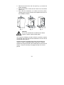
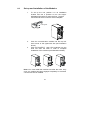
1. Remove the packaging bands and lift up the cardboard box
to remove it (see Fig. 1)
19
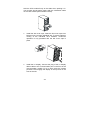
2. Remove the foam from the unit (see Fig. 2); remove the
plastic wrapping;
3. Remove the lower module and the foam from the frames
(see Fig. 3);
4. Now, with the assistance of at least one other person,
carefully lift the system cabinet off the pallet and move it to
the installation location.
Fig. 1
Fig. 2
Fig. 3
Attention
Do not use a lowlift truck or forklift truck to lift the
system or battery cabinet off the pallet!
The original packaging provides effective protection against
mechanical shocks and should be retained so the unit can be
transported safely later on.
Please keep plastic packaging bags away from babies and
children in order to safeguard against suffocation accidents.
Handle the components with care. Please take into account the
weight. It may be necessary to engage the help of a second
person.
20
4.2
Transport to Installation Site
The PROTECT 1.M is equipped with transport rolls for easy
transport to the intended installation site. It is recommended to
install the UPS where:
♦ The connection work can be conveniently carried out;
♦ There is enough space for proper operation and, if
necessary, for periodic and extraordinary maintenance
work; in this regard, the connection cables should be
long enough to move the UPS (to open the UPS if
necessary) without having to switch it off.
♦ The UPS is protected against external atmospheric
influences;
♦ The humidity and the ambient temperature are within the
limits;
♦ The fire protection standards are observed.
The battery service life strongly depends on the ambient
temperature. Ambient temperatures between +15 °C and +25
°C are optimum.
Attention!
Only transport the PROTECT 1.M in an upright
position! Never tilt or cant it; avoid displacing
the centre of gravity!
Make sure that no magnetic storage media are stored and/or
operated close to PROTECT 1.M.
21
4.3
Set-Up
Note the following points when setting up the UPS system and
its external battery units (special accessories):
♦ The contact surface must be smooth and level. It must
also be sufficiently strong and sturdy to avoid vibration
and shocks.
♦ Make sure that the mounting is able to support the
weight, especially in conjunction with external battery
units (special accessories).
♦ Set up the units so that adequate air circulation is
assured. There must be at least 100 mm clearance at
the back for ventilation purposes. Do not block the intake
openings on the front and, if present, on the side of the
unit. There must be a gap of at least 50 mm here.
♦ External battery units must be placed on the side of the
UPS system. To ensure the greatest possible
mechanical stability, do not place the external battery
unit(s) above or below the UPS system.
♦ Avoid extreme temperatures! We recommend an
ambient temperature of 15 °C to 25 °C in order to
maximise the service life of the batteries. Do not expose
the units to direct sunlight or operate them close to other
heat sources such as radiators.
♦ Protect the units against external effects (in particular
moisture and dust). In this regard, please also refer to
the instructions in chapter 3, page 14 in these operating
instructions.
If you transport the unit from a cold room into a warm one, or if
the room temperature suddenly drops, then condensation may
form inside the unit. To avoid any damage due to
condensation, let the unit acclimate for 2 hours before you
switch it on.
22
5
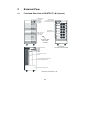
External View
5.1
Front and Rear View of PROTECT 1.M (chassis)
LED indicators
LC display
Keys for
UPS menu
navigation
System On/Off
Communication port
Communication module
UPS modules
PROTECT 1.040
Slot cover caps
with intake air
channelling
Front view with
slot covers
mounted
Communication slot
RS485
RS232
RS485
RS485
Front view
with slot covers removed
Cover for mains input
switch
Cover with electronic interlocking
for manual bypass switch
Connection terminal cover
Rear view of PROTECT 1.M
23
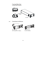
5.2
Front/Rear and 3D View
PROTECT 1.040 (UPS module)
Handles with latching for easy removal or insertion
of a PROTECT 1.040 UPS module
Fans
5.3
Front view
RS232
Fans
Blade-connect male
Rear view
Orientation markings for optimum
displacement of the centre of gravity
when holding a PROTECT 1.040 UPS
module
3D view
24
Front and Rear View
(communication module)
Blade-connect
Co
nnec tor
REAR VIEW
Rear view
Handle
Ha
nd le
LCD port
Communication
c om
m unic a tion
for connecting
the p ort
LC display
SIDE VIEW
FRONTVIEW
Front
view
5.4
3D view
Front View of LCD Panel
LCD
Com m cable
unic atio n Line
LCD
connection
Slot cover cap
with integrated LC display
Slot cover cap
for UPS modules
25
5.5
Display Panel
1. "Normal": The green LED lights when the UPS is
supplying the loads with voltage via the inverters
(normal operation).
2. "On Battery": The yellow LED lights when the UPS is
supplying power from the battery.
3. "Bypass": The yellow LED lights when the UPS is
supplying the loads with mains voltage from public
utility's mains.
4. "Fault": If the UPS is not operating without faults, the
red LED lights continuously and a continuous alarm
signal sounds; alternatively, the red LED flashes and
an alarm signal sounds at the same time.
5. Graphic LC display, for functions such as UPS status
display
6. ↵ Select/confirm entry (return)
7. ▼ Scroll down
8. ▼ Scroll up
9. ESC: Cancel
26
6
Installation
6.1
Installation Notes
1. This unit must be installed by qualified personnel in
accordance with the locally applicable electrical
regulations.
2. The PROTECT 1.M uses fans for cooling, which
means sufficient ventilation must be provided at the
installation location (see also chapter 6.2:
Installation area).
3. A battery system with a nominal DC voltage of 120
Vdc is required as the external battery for the
PROTECT 1.M. The battery capacity and the battery
pack can be selected according to the user's
requirements.
As
an
option,
appropriately
preconfigurations with a wide range of capacity
values can be purchased directly from AEG Power
Solutions.
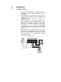
4. Connection diagram: The PROTECT 1.M has two
input modes: A single-phase input and a threephase input. The PROTECT 1.M detects the input
mode and selects the corresponding operating
mode automatically.
a. Connection with single-phase input
27
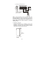
b. Connection with three-phase input
Note: If using three-phase mains connection, make sure
the phase sequence is correct. The UPS cannot start up if
the phase sequence is wrong, and an alarm will sound. At
the same time, "Phase sequence error" appears on the LC
display. Make sure the neutral conductor is connected
correctly as well.
5. Installation clearances
> 30cm
Mo
re
th
ar
e
80
cm
Mo
re
th
ar
e
30
cm
A gap of at least 80 cm is required in front of the
PROTECT 1.M and at least 30 cm behind the UPS for
maintenance purposes. No objects should be placed
closer than 30 cm to the side of the UPS.
> 80cm
28
5. Connection cross-sections and fuse protection
29
i
If you are using fuse load break switch for mains
fusing, please select miniature circuit breakers
with "D" characteristic.
Route wires individually to guarantee reliable
strain relief.
Preferably use special rubber-insulated wire
NSGAÖU or NSGAFÖU, NYY or Radox 4GKW-AX.
30
6.2
Set-up and Installation of the Modules
1.
To set up the unit, position it in its installation
location and use a spanner to turn the heightadjustable feet until they reach the floor. The feet
are located at the four corners of the baseplate.
Locking
foot
Bra
ke pad
2.
3.
Push the communication module into the top lefthand corner of the uppermost slot (see illustration
above).
Push all PROTECT 1.040 UPS modules into the
slots one after the other in order to complete
installation of the modules (see illustrations below).
Note: You must install the modules one after the other. Only
once one module has been engaged completely in the frame
can the next one be installed.
31
Hold the UPS module firmly at the sides when pushing it in.
Your thumbs should make contact with the orientation marks
on the UPS module (see illustration below).
4.
Install the slot cover caps: Insert the slot cover caps from
bottom to top over each individual slot. To ensure optimum
cooling of the individual UPS modules, continuous
operation is only permitted with the slot cover caps in
place.
5.
Install the LC display: Connect the plug of the LC display
ribbon cable to the communication port on the front of the
communication module. Fix it in place using the screws
provided. Then engage the display in the top rack on the
front of the unit.
32
7
Adding/Removing Modules
7.1
Active Redundancy
n+x technology is one of the most reliable configurations. "n"
represents the minimum number of PROTECT 1.040 UPS
modules that requires the total power; "x" represents the
number of redundant PROTECT 1.040 UPS modules, i.e. the
number of fault-tolerant modules that the system can handle at
the same time. Assume the apparent output power to be
achieved is 15 kVA, for example. One module of the
PROTECT 1.M delivers 4 kVA. This means it is necessary to
select n=4 at least (4 x 4 kVA = 16 kVA). If x = 2 then two
additional UPS modules would provide active redundancy.
In the sample configuration above, each of the 6 UPS modules
delivers a 2.5 kVA proportion of the overall power. If one
module were to fail, the five other modules would each deliver
3 kVA. If two UPS modules fail, the remaining four modules
would each deliver 3.75 kVA. The system indicated here
therefore permits a maximum of two modules to fail, although
the probability of two modules failing simultaneously is
considerably lower than that of one module failing.
Furthermore, additional modules guarantee that the overall
system has a higher overload capacity, for instance.
You can increase capacity by adding to the number of modules
in the PROTECT 1.M. Do this by connecting from one to six
modules in parallel. The six UPS modules function
autonomously and are independent of one another. Faulty
modules can easily be renewed during ongoing operation at
any time.
7.2
Installing and Removing UPS Modules
The PROTECT 1.M uses what is referred to as hot-swappable
technology, which means you can install or uninstall, add or
remove modules irrespective of whether the unit is switched on
or off. If the UPS is operating with loads, before removing any
modules you should check that the remaining modules are
capable of providing sufficient power otherwise there may be
an overload.
33
7.2.1
Basic procedure for installing a PROTECT 1.040 UPS
module
1. Remove the slot cover cap from the rack in which the UPS
module is going to be installed.
2. Grip the UPS module at the sides with both hands. The
black dots on the top of the UPS module serve as
orientation marks for where to position your thumbs in
order to have the centre of gravity in the optimum position.
Slowly and carefully push the module into the housing slot.
Make sure that the warning notice is facing upwards.
3. Make sure that the module has been completely pushed
into the shaft and has clipped in with a clearly audible
"click".
4. Reinstall the cover plate.
7.2.2
Basic procedure for removing a PROTECT 1.040 UPS
module
1. Remove the slot cover cap from the rack from which the
UPS module is going to be removed. Use both hands to
pull the handles on the sides. Pull until you see the "●"
markings on the top of the UPS module you are pulling out
(the handle has a detent position, and only when the lever
is pressed is it possible to pull the module out).
2. Then hold the module with both hands with your thumbs at
the "●" markings and pull it out.
Note: Pull the module slowly and without exerting too much
force. In particular, watch out for the shift in the centre of
gravity when the module leaves the slot!
34
8
Operating and Maintenance
8.1
Operation
1.
2.
3.
4.
5.
Make sure that the phase sequence is correct if you are
using a three-phase mains connection (L1, L2, L3). If you
are using a single-phase mains connection, make sure
that phase L1 has been selected and correctly connected
to the UPS.
Furthermore, make sure that the neutral conductor has
been connected properly and that the system is
adequately earthed.
Check the polarity of the battery system. Make sure that
the (+) and (-) poles of the connection match those of the
battery casing. Now switch the battery system "ON" using
the fuse load break switch.
Switch the input protection switch on the rear of the UPS to
"ON". The fans start operating immediately.
Now set the "system start switch" behind the slot cover
cap of the LC display to "ON" and follow the instructions
on the LC display.
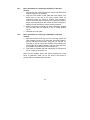
Note: The diagrams below show examples for the displays with
a three-phase connection for the UPS; in spite of the slight
differences they also apply accordingly to the AC voltage
connection. The content of the diagrams is only intended for
display purposes.
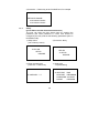
1) After step 4.
2) Wait about 15 seconds
IMPORTANT: Step 5 only now.
Æ UPS ON
SETUP
INQUIRE
LCD SELFTESTING …
PT1.M UPS
UPS SELFTESTING
PLEASE WAIT A MOMENT
35
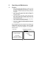
4) Press ▼ for the following
information
3) Press ESC
LOAD: 0%
BATT: 137
I / P VOLT: 232 232 231
O / P VOLT: 0
O / P FREQ: 0.0Hz
STATUS: NO OUTPUT
OUTPUT PARAMETER
RN
SN
TN
VOLT: 0V
CURR: 0A
FREQ: 0.0Hz
Note: When the mains is connected for the first time, the UPS does
not output any voltage (Figs. correspond to this status)
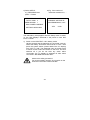
5) Press ▼ again
for the following information
6) Press ▼ again
for the following inform.
INPUT PARAMETER
RN
SN
TN
VOLT: 232
232
231
FREQ: 50.0Hz
RST INPUT
POWER PARAMETER
kW
kVA
TOTAL: 0.00 0.00
UPS1: 0.00 0.00
UPS2: 0.00 0.00
Note: The status of each UPS module is displayed cyclically in the
bottom two lines.
7) Press the ▼ key again for the following information
BATTERY PARAMETER
BAT VOLT: 136V
VOLUME: 100%
STATUS: CHARGING
Note: Battery status is
CHARGING, DISCHARGE
or BATT OPEN (battery not
connected).
36
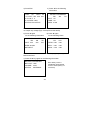
8.1.1
Start-up
1) Switch on
2) Press the
↵ / Return key
3) Press the
▼ key
CONFIRM
TURN UPS ON
Æ NO, CANCEL
YES, CONFIRM
Æ UPS ON
SETUP
INQUIRE
4) Once again, press the
↵ / Return key
LOAD: 0%
BATT: 136
I / P VOLT: 232 232 231
O / P VOLT: 230
O / P FREQ: 50.0Hz
STATUS: 3 PHASE I / P
UPS IS TURNING ON
PLEASE WAIT…
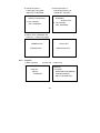
8.1.2
Shutting down
1) Switch off
2) Press the
↵ / Return key
3) Make selection
UPS OFF SELECTION
ÆSWITCH TO BYPASS
TURN OFF OUTPUT
Æ UPS OFF
SELFTEST
SELFTEST
INQUIRE
37
3) Switch-off option 1:
Load supply via bypass
"SWITCH TO BYPASS"
4) Switch-off option 2:
Load supply directly off
"TURN OFF OUTPUT"
CONFIRM
SWITCH TO BYPASS
Æ NO, CANCEL
YES, CONFIRM
CONFIRM
WARNING:
OUTPUT OFF
Æ NO, CANCEL
YES, CONFIRM
5) Select "YES, CONFIRM" and
press the ↵ / Return key again
8.1.3
TURNING OFF
UPS IS OFF
PLEASE WAIT…
PRESS ANY KEY…
Inquiries
1) Menu inquiries
2) Press the ↵ / Return key
INQUIRY
Æ PHONE
MAINTAIN PROCEDURE
ALARM CONTROL
ONLY FOR SERVICE
UPS ON
SETUP
Æ INQUIRE
38
3) Press the ↵ / Return key at the "PHONE" item, for example
RETAILER PHONE:
XXXXXXXXXXXX
XXXXXXXXXXXX
8.1.4
Setup
(press ESC to exit the aforementioned menus)
The user can enter the User Setup menu by entering the
password (the initial password is "1234" and should be
changed by the user) and set the following parameters (UPS in
BYPASS mode!):
1) Setup menu
(not in Start-up menu)
2) Press the ▼ key
ÆUPS ON
SETUP
INQUIRE
UPS ON
Æ SETUP
INQUIRE
3) Enter the password;
press the ↵ / Return key
4) Select the
required setting
SETUP
Æ SELFTEST
RE-START
PASSWORD
PHONE
Æ USER KEY: *****
39
TIME
REDUNDAN
VOLTAGE
FREQUEN
5) Select SETUP,
e.g. REDUNDAN and
6) E.g. if the number of
redundant modules is 0, …
press ↵ / Return
SETUP REDUNDANCE
TOTAL NUM: 3
ÆREDUN NUM: 1
MAX POWER CURRENT
SETTING: 8kVA/5.6kW
WARNING:
CURRENT SETTING IS
NO REDUNDANCY, OK?
YES
Æ NO
The redundancy setup applies after the Setup menu is exited,
i.e. the UPS displays "Overload" if the power is more than
8 kVA / 5.6 kW.
7) Switch on the PROTECT 1.M in battery mode:
Having ensured that the batteries are connected correctly,
switch the battery fuse-switch disconnector to "ON". Then
press the system switch (located behind the LC display)
from "OFF" to "ON". The displayed menu is similar to that
of mains current mode. Now switch on the UPS. The UPS
switches off if you do not start any action within
15 seconds; the LC display is switched off after about
10 minutes: "NO MODULE DETECTED"
Observe the safety precaution!
For personal safety reasons, do not switch on the
UPS when the mains is disconnected!
40
8.2
Maintenance
1.
2.
3.
Maintenance of the UPS and battery replacement should
be performed by well trained expert personnel.
Batteries that have not been used for some time must be
charged up every three months at normal ambient
temperature and every two months if the ambient
temperature is high.
The three switches on the back, from top to bottom, are as
follows: Mains fuse-switch disconnector, manual service
bypass switch and output switch. Switching the mains
fuse-switch disconnector on causes mains voltage to be
supplied to each module of the PROTECT 1.M. Switching
the output switch on allows output voltage to be delivered
from the modules of the UPS to the loads. The
maintenance switch is used for UPS maintenance. The
UPS can only run in inverter operation if the manual
service bypass switch is switched off and the cover has
been fitted.
Note: Make sure that the PROTECT 1.M has been
changed over to bypass operation before you switch on
the manual service bypass switch. The load connection is
immediately supplied with voltage when the manual
service bypass switch is actuated. Only trained and
qualified personnel should operate this switch.
41
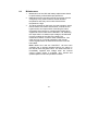
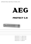
8.3
Shutdown and UPS Management Software
The "CompuWatch" software specially developed for these
purposes by AEG continuously checks the mains supply and the
UPS status.
In conjunction with the "intelligent" UPS, this guarantees the
availability of the EDP components as well as the data security.
The "CompuWatch" shutdown software supports different
operating systems, e.g. Windows 98SE/ME, Windows
NT/2000/XP, Windows Vista, Linux SUSE, Linux RedHat, Novell
Netware, IBM AIX, HP-UX, SUN Solaris, Mac OS, and others.
Example of a "CompuWatch" screen:
Refer to the manual on the CD for details about installing the
software on the various operating systems. Download of
updates at www.AEGpartnerNet.com >> PRODUCTS >>
Software >> CompuWatch.
42
9 Communication Interfaces
The PROTECT 1.M has RS232 and RS485 interfaces as well
as an expansion slot: As external connections, it is possible to
use either an AS400 card (optional) or an SNMP/ SNMP PRO
card (optional) for the expansion slot.
1. The standard RS232 interface is for the "CompuWatch"
control software.
2. The RS485 connection makes it possible to monitor and
control all the functions of the UPS from a remote location.
3. The optional AS400 connection is for AS400 users who
want to control the UPS directly by using the UPS control
function of the AS400 system.
4. In addition, the expansion slot is for the SNMP/ SNMP
PRO card (optional accessory), which permits remote
monitoring of the UPS via the Internet.
5. If you have any questions about using the aforementioned
communication interface connections, please contact our
customer support.
43
10
Troubleshooting and Fault
Rectification
If error messages are displayed, please refer to the following
table in order to localise the fault that has occurred and to find
information about what measures to take to rectify the fault. If
you cannot resolve the problem(s), please contact the Service
Center (see page 5 "Hotline").
1. Check whether the UPS connection, and specifically the
mains connection, has been made correctly.
2. Check whether the input voltage has been applied correctly
(check for phase(s) connected to the neutral conductor and for
the phase sequence, if appropriate).
3. Check the connection of the battery system (polarity and nominal
voltage).
4. Make a note of the status of the unit when the fault occurred
(LC display) and the error code number that is displayed.
Overview of fault messages
PROBLEM
Error/fault LED lights up, periodic
warning signals
Error/fault LED lights up,
continuous warning signal
Battery discharge time is 1/3 shorter
compared to 1st time
POSSIBLE CAUSE
SOLUTION
Overload in normal / bypass or battery
operation
Reduce the load.
Applied mains not in tolerance range
Check whether input cabling and UPS
input voltage are normal.
Battery system faulty / not connected
Check whether the voltage of the battery
system is correct and that the battery fuseswitch disconnector is made.
UPS fault
Battery system aged/reached end of useful
life
Contact the Customer Service Center.
Charging error
LC display dark or faulty
LCD displays that data cable is not
attached correctly (?)
Make sure that the communication module
has been installed correctly; check both
plugs of the ribbon cable for the LC
display are connected correctly.
CompuWatch or SNMP(pro) do
not detect the PROTECT 1.M >>
No communication
Software status of CompuWatch or
firmware of SNMP(pro) card outmoded;
error in computer configuration
Download the latest software /
firmware from the AEG homepage.
Check the communication cable.
The LC display does not display
any inserted UPS modules
Modules, housing or units are not
connected correctly.
Pull the module out and re-insert it into the
slot (click!) or use a different slot.
Mains power is connected but the
UPS does not start operating.
Mains not in tolerance; phase loss or
possible phase sequence error; cover
removed from bypass switch.
Check the mains voltage and UPS
connection; replace cover of bypass
switch if removed.
44
11
Reference Table for the Display and
UPS Operating Problems
11.1 Normal operation
Operating
status /
Warning signal
LC displays
Notes
Fault
(Fault)
Bypass
(Fault)
Battery
(On Battery)
Normal
(Normal)
Operating
problems
LED indications
Mains in
tolerance
range
None
Mains not in
tolerance, i.e.
batt. operation
1 acoustic signal
every 4s
"utility power
is abnormal"
11.2 Battery Operation
Battery voltage
in tolerance
range
1 acoustic signal
every 4s
"utility power
is abnormal"
Battery voltage
not in tolerance
range
1 acoustic signal
every 2s
"battery voltage
is too low"
Check battery
system; poss.
Reduce load
11.3 Bypass Operation
Operating
status /
LED indications
Operating
problems
Fault
(Fault)
Bypass
(Fault)
Battery
(On Battery)
Normal
(Normal)
Warning signal
Mains in
tolerance
range;
bypass mode
1 acoustic
signal every
2 min.
Mains not in
tolerance
range;
bypass mode
1 acoustic
signal every 4 s
45
LC displays
Notes
Alarm stops
when UPS
returns to
normal mode
"utility power
is abnormal"
USV output
voltage is
switched off
11.4 Warning Signal if Battery System Not
Connected, e.g. battery fuse failure
Operating
status /
LC displays
Notes
Bypass
mode
1 acoustic signal
every 4 s
"UPS is not
connected to
the battery"
Check battery
system; poss.
fuse fault?
Normal
mode
1 acoustic signal
every 4 s
"UPS is not
connected to
the battery"
Check battery
system; poss.
fuse fault?
Fault
(Fault)
Bypass
(Fault)
Battery
(On Battery)
Normal
(Normal)
Warning signal
Operating
problems
LED indications
11.5 Warning Signal for Phase Loss or Phase
Sequence Error
Operating
status /
LC displays
Notes
Phase loss;
Phase
sequence
error; bypass
1 acoustic signal
every 2 s
"utility failure
and sequence
error"
No output
voltage; check
UPS connection
Mains failure
normal mode
1 acoustic signal
every 4 s
"utility failure"
alarm code
02 03 09
Check UPS
input cabling
Note:
Fault
(Fault)
Bypass
(Fault)
Battery
(On Battery)
Normal
(Normal)
Warning signal
Operating
problems
LED indications
= LED lights up
= LED flashes
46
11.6 Overload Protection
Operating
status /
Warning
signal
LC displays
Notes
Fault
(Fault)
Bypass
(Fault)
Battery
(On Battery)
Normal
(Normal)
Operating
problems
LED indications
Overload in
normal operation
UPS warning
1 acoustic
signal
every 2 s
"Output
overload"
Reduce the load
Overload in
normal operation
> Switchover
Continuous
warning
signal
"Output
overload"Alarm
code: 46
Reduce the load
Overload in
battery operation
UPS warning
1 acoustic
signal
every 2 s
"Output
overload"
Reduce the load
Overload in
battery operation
> switch-off
Continuous
warning
signal
1 acoustic
signal
every 2 s
Overload in
bypass
operation
Note:
"Output overload"
Reduce the load
Alarm code: 46
"Output
overload"
Reduce the load
= LED lights up
= LED flashes
If you cannot solve the problem that has occurred, stop the entire
procedure, switch off the UPS and disconnect the UPS from the
mains. Please contact our hotline in this case (see page 5).
Please have the serial number of the unit as well as the
purchase date at hand. The hotline will provide you with technical
support and can inform you about further procedures once you
have described the problem.
47
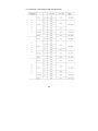
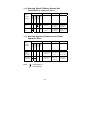
12
Minimum Number of Battery Packs
Batteries with different capacity have specific charging and
discharging characteristics. Standard configurations have been
defined in order to make optimum use of the service life. The
hatched part shows the permitted configurations.
Configuration table for battery cabinet systems equipped with
24 or 28 Ah battery blocks
Power
24/28 Ah x 1 24/28 Ah x 2 24/28 Ah x 3 24/28 Ah x 4 24/28 Ah x 5 24/28 Ah x 6
4 kVA
8 kVA
12 kVA
16 kVA
20 kVA
24 kVA
Configuration table for battery cabinet systems equipped with
38 or 42 Ah battery blocks
Power
38/42 Ah x 1 38/42 Ah x 2 38/42 Ah x 3 38/42 Ah x 4 38/42 Ah x 5 38/42 Ah x 6
4 kVA
8 kVA
12 kVA
16 kVA
20 kVA
24 kVA
Configuration table for battery cabinet systems equipped with
65 or 75 Ah battery blocks
Power
65/75 Ah x 1 65/75 Ah x 2 65/75 Ah x 3 65/75 Ah x 4 65/75 Ah x 5 65/75 Ah x 6
4 kVA
8 kVA
12 kVA
16 kVA
20 kVA
24 kVA
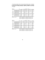
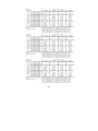
48
The following tables show the achievable standby times according
to the UPS expansion level and capacity utilisation as well as
depending on the optional battery cabinet units that are connected
ex-works:
49
50
13
List of terms
13.1
Technical terminology
DC/DC booster
Circuit technology for increasing a DC voltage to a higher
voltage level
SBS
Static Bypass Switch
Appliance protection
Term from overvoltage technology
Classic mains overvoltage protection consists of lighting
surge arrester (class B), overvoltage protection (class C)
and, finally, the so-called appliance protection (class D)
- see also the http://www.phoenixcontact.com website
(topic "TRABTECH")
IGBT
Insulated Gate Bipolar Transistor
The latest design of high-performance transistors with
minimum control power requirement (MOSFET
structure) and minimum losses on the output side
(structure of a bipolar transistor)
Class D
See appliance protection
LED
Light Emitting Diode
Electronic semi-conductor component, commonly
referred to as an LED, used for optic signalling.
PFC
Power Factor Correction
Circuit technology for minimising system disturbances
(particularly important when connecting non-linear
loads)
PWM
Pulse Width Modulation
Here: circuit technology for generating a sinusoidal
voltage of the highest quality from an existing DC
voltage
SNMP
Simple Network Management Protocol
A protocol encountered frequently in networks for
managing / handling components
VFD
Output Voltage and Frequency Dependent from mains
supply. The UPS output is dependent on mains voltage
and frequency fluctuations. Earlier designation:
OFFLINE
VI
Output Voltage Independent from mains supply
The UPS output is dependent on mains frequency
fluctuations, but the mains voltage is prepared by
electronic / passive voltage control units. Earlier
designation: LINE-INTERACTIVE
VFI
Output Voltage and Frequency Independent from
mains supply. The UPS output is independent of mains
voltage and frequency fluctuations. Earlier designation:
ONLINE
51
Notes
52
Notes
53
Notes
54
Notes
55
Guarantee Certificate
Type: …….……………….…......................................................
Unit number: ….………….…..……………................................
Date of purchase:………………...........……………………........
Dealer stamp / signature
Errors and changes excepted.
AEG Power Solutions GmbH
Emil-Siepmann-Straße 32
59581 Warstein-Belecke
Germany
Operating instructions
BAL 8000015763_02 EN
56