1
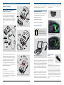
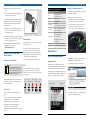
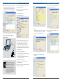
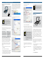
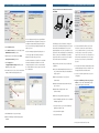
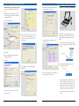
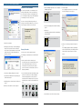
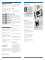
Mastertech Vehicle Communication Interface (VCI) User’s Guide F00E900173 The Mastertech Vehicle Communication Interface User’s Guide provides an overview of the tool. Certification Specifications Pollution Degree: 2 Operational Altitude: 2000 m. (6,500 ft.) latest product information available at the time of Operational Humidity: 80% publication. The right is reserved to make changes at any Operational Temperature: 0°C to 50°C time without notice. Electrical Input: 7-32 VDC at 750mA max. No part of this publication may be reproduced, stored any means, including but not limited to electronic, mechanical, photocopying, recording, or otherwise, without the prior written permission of Bosch Diagnostics. This includes all text, tables, illustrations, Warranty Information The Mastertech Vehicle Communication Interface is warranted by Robert Bosch LLC to be free of defects in material and workmanship for two years. Cables, adapters, and accessories are warranted for a period of Power Supply one year. This warranty period is from the date of sale The Mastertech VCI base kit includes an external AC to DC power supply with 100-240 VAC 50/60 Hz input. Output is 12 volts at 1.25 amps. and charts. to the original consumer. If the product is found to be defective during this period, the product can be returned uu Warnings indicate there is a possibility of injury to you or other people. uu Cautions indicate the possibility of damage to equipment. uu Notes providing additional information are separated from the text but do not appear in bold. to Robert Bosch repair facility and will be repaired or Refer to the Repair Manual for the vehicle being tested for replaced free of charge at the sole discretion of Robert further Warnings, Cautions, and Notes. Bosch LLC. This warranty does not cover any part that Note If you are reading this guide on your computer, note that the figures and illustrations are hyperlinked to the text. To view a figure, simply click on its reference. FCC Compliance This equipment has been tested and found to comply with the limits for a Class A digital device, pursuant to Part 15 of the FCC rules. These limits are designed to provide reasonable protection against harmful interference when the equipment is operated in a commercial environment. This equipment generates, uses, and can radiate radio frequency energy. If not installed and used in accordance with the instruction manual, it may cause harmful interference to radio communications. Operation of this equipment in a residential area is likely to cause harmful Caution has been abused, altered, used for a purpose other These devices are intended for indoor use only. than that of which it was intended, or used in a manner damages. Foreword The Shop Foreman Pro and Mastertech Vehicle Repair Service Communication Interface are designed for use by trained If you suspect that you have a problem with this product, service personnel to diagnose and repair automotive electronic systems. Every attempt has been made to provide complete and accurate technical information based on factory service information available at the time of publication. However, the right is reserved to make changes at any time without notice. To familiarize yourself with the Shop Foreman Pro applications and its capabilities, and how to use it, please read through the User’s Guides before putting the VCI to work. Shop Foreman Pro provides the following capabilities: correct the interference at his or her own expense. uu Electronic Control Unit (ECU) Data Transfer VDE and CSA Certification (Europe and Canada) This equipment complies with the requirements of VDE you are operating the product properly. If it is determined that a problem exists, please contact the Robert Bosch Repair Center. North America: 800-321-4889 Japan: (045) 222-0960 Australia: +61 (2) 98905701 Europe: 49 (0) 607-8428 25 If the product needs to be returned for repair, please package the product and send it freight prepaid to Please enclose your telephone number, return address, For the location of vehicle Electronic Control Units (ECUs) Warning — Set Parking Brake To help avoid personal injury, always set the parking brake securely and block the drive wheels before performing any checks or repairs on the vehicle. Caution Ensure cables and adapters are firmly connected before starting to use the VCI. Always read the instructions completely before attempting a new procedure. and an explanation of the problem. If the product is determined to be in warranty, it will be repaired or replaced at no charge and returned freight prepaid. If determined to be non-warranty, it will be repaired for a nominal service fee. and Data Link Connectors (DLCs), refer to the Repair Robert Bosch LLC Manual and the electrical wiring diagram for the vehicle 2030 Alameda Padre Serra, Suite 300 being tested. Santa Barbara, CA 93103-9903 VCI User’s Guide | Version 3.1 | April 2012 When performing any checks with the engine running in an enclosed space such as a garage, be sure there is proper ventilation. Never inhale exhaust gases; they contain carbon monoxide—a colorless, odorless, extremely dangerous gas which can cause unconsciousness or death. the Robert Bosch Repair Center as instructed by the uu Future expandability, including diagnostic applications unacceptable radio or TV interference. Warning Canada: 905-668-2664 Technical Service representative (No C.O.D.s please). Improper use or maintenance neglect may cause Operating Precautions read the operating instructions carefully to ensure that uu Shop network communications (LAN and WLAN) Location of Vehicle ECUs and Test Connectors 0871/6.78 and CSA Class No. 3631 05,DQD No.548. inconsistent with instructions regarding its use. This warranty also excludes all incidental or consequential interference, in which case the user will be required to Robert Bosch LLC Warnings, Cautions, Notes In the VCI User’s Guide: Everything contained in this manual is based on the in any retrieval system, or transmitted in any form by Warranty and Repair VCI User’s Guide | Version 3.1 | April 2012 Robert Bosch LLC Contents i FCC Compliance i VDE and CSA Certification (Europe and Canada) i Using This Manual iForeword i Location of Vehicle ECUs and Test Connectors i Warranty and Repair i Warranty Information ii Repair Service ii Warnings, Cautions, Notes ii Operating Precautions 1 Product Description 1 Mastertech Vehicle Communication Interface Kit Components 1 VCI Connections 2 Host Computer Interface 2 Universal Serial Bus (USB) 2 Local Area Network (LAN) 3 LAN with Network Router—Straight Ethernet Cable 3 Wireless Local Area Network (WLAN) 4 VCI Manager Application 5 Mastertech Vehicle Communication Interface 6 Getting Started 6 Using the VCI Manager Application 6 Identifying Your VCI 6 Starting the VCI Manager Application 7 Update VCI Tester Software 8 VCI Network Communications Setup Functions 9 Clear Network Settings 9 Enable Wired Ethernet 14 Setup the VCI for Ad-Hoc Wireless Communication 18 Setup Your PC for Ad-Hoc Communication 19 Recover VCI Tester Software 19 Recovery Procedure 21 Power On Self Test 21 Connecting the VCI to the Vehicle 21 Powering the Mastertech Vehicle Communication Interface 21 120VAC/12VDC, 1A Power Supply 21 Vehicle Battery 21 Finishing Up 21 Cleaning and Storing Your VCI 22 Battery Replacement 22 Replacing the Batteries 23Notes 25 Glossary and Abbreviations Features 5 Data Link Connector And Cable 5 Power Source 5 Battery Operation 5LEDs Robert Bosch LLC VCI User’s Guide | Version 3.1 | April 2012 VCI User’s Guide | Version 3.1 | April 2012 Robert Bosch LLC 1 | Product Description | Mastertech VCI Kit Components Product Description | Host Computer Interface | 2 Product Description For a description and location of the standard indicators USB cable is inserted into the slot, and then plugged in as (LEDs) and the power button, see Figure 1-3. shown in Figure 1-6. Mastertech Vehicle Communication Interface Kit Components Host Computer Interface The Mastertech Vehicle Communication Interface (VCI) The VCI communicates with a host computer using three possible interfaces between the VCI and the PC: arrives in a kit which also contains a J1962 16/26 Pin DLC Cable, 120VAC/12VDC, 1A Power Supply, USB uu Universal Serial Bus (USB), cable, cable keeper and the media containing diagnostic application software (figure 1-1). A description of the uu Local Area Network (LAN), and VCI hardware and software is included in the following uu Wireless Local Area Network (WLAN). sections. Figure 1-2. Vehicle Connections to the VCI Universal Serial Bus (USB) Note The USB connection takes priority over an ethernet or a WLAN connection. All configuration changes or software updates are only allowed using the USB connection. Figure 1-6. Securing the USB Cable ESI[tronic] 2.0 Shop Foreman Pro Figure 1-1. Mastertech Vehicle Communication Interface Kit Figure 1-3. PC Connections on the VCI The VCI is used by professional technicians as an aid Figure 1-5. USB is the first connection in diagnosing and repairing automotive electrical and electronic systems. The VCI is the connection between A LAN consists of a two or the diagnostic software applications running on the PC The VCI has a fixed USB configuration (static IP address) and a vehicle’s electrical and electronic systems. which cannot be changed. This ensures that the VCI can For details about the diagnostics applications that are always be connected to a PC running diagnostic software compatible with the VCI, refer to the Bosch diagnostics and the VCI Manager application regardless of changes website; www.boschdiagnostics.net. to LAN or WLAN configurations required by the local network. Refer to Using the VCI Manager application for VCI Connections details. For the location of the connectors for DC power and The connectors on the USB cable are slip-in connectors vehicle communication on the VCI, see Figure 1-2. that do not securely lock in place. In order to keep the For the location of the connectors for PC communication Figure 1-4. PC Standard Indicators (LEDs) and Power Button on the VCI, see Figure 1-3. Robert Bosch LLC Local Area Network (LAN) USB cable connected, secure it to the VCI using the supplied cable keeper. The cable keeper is attached to the VCI case with a supplied 2.5 mm hex-head screw, the VCI User’s Guide | Version 3.1 | April 2012 VCI User’s Guide | Version 3.1 | April 2012 more computers connected together using ethernet Latch cables. The connectors on both ends of an ethernet cable are latched. To disconnect them you must press down on the latch while you pull the connector out. The VCI’s LAN communication is setup and configured as required for the user’s local area network using a PC running the VCI Manager application. The VCI can be networked using a Direct Connection (crossover ethernet cable) or a network router (straight ethernet cable). A brief description of each of these network configurations follows. Robert Bosch LLC 3 | Product Description | Host Computer Interface uu Direct Connect—Cross-over Ethernet Cable uu LAN with Network Router—Straight Ethernet Cable Product Description | Host Computer Interface | 4 Many offices and shops have computers connected The procedure for setting up ad-hoc wireless To start the VCI Manager application, launch the together using ethernet cables, network routers, and other communications requires two steps: appropriate diagnostics software application. This is items such as printers and modems (internet connection for email). Figure 1-8, shows one computer connected to a network router which is then connected to two VCIs. In an actual network there will typically be several computers connected into network routers allowing any of the computers to connect to and control one of the VCIs. Refer to Enable Wired Ethernet for details on configuring your VCI for communication on a wired ethernet. 1. Use VCI Manager to configure your VCI interface. Refer either Shop Foreman Pro or ESI[tronic] 2.0. to Setup the VCI for Ad-Hoc Wireless Communication Note for details. Clicking the Connect button in VCI Manager application establishes a connection to the VCI hardware via USB for configuring network connectivity (wired/wireless) and for updating the VCI software. Once VCI Manager is closed, the connection to the VCI hardware is no longer enabled. If VCI Manager is reopened, you must use the Connect button to re-establish the connection to the VCI hardware for configuration or software update purposes.. 2. Configure your wireless communications software on your PC. Refer to Setup Your PC for Ad-Hoc Communication for details. Access Point Wireless—Infrastructure Mode Wireless Local Area Network (WLAN) Note The VCI’s 802.11B/G WLAN connection is setup and Refer to your access point manual for network configuration details and suggested operating distances. configured as required for the user’s local wireless network Figure 1-7. Direct Connect—Cross-over Ethernet able using a PC running the VCI Manager application. The VCI supports both Direct Connect (ad-hoc) and Access Point wireless configurations. A brief description of each of these Figure 1-7, above, shows a computer connected to a VCI using a cross-over ethernet cable. In this configuration the computer can communicate directly to the VCI. Most computers have only a single network interface connection so in this configuration you will only have communication to the VCI. Refer to Enable Wired Ethernet for details on configuring your VCI for communication on a wired ethernet using a cross-over cable. launch the VCI Manager application. The access point wireless option allows you to connect wireless communication configurations follows. your VCI to a WLAN. Depending on the configuration of Direct Connect (ad-hoc) Wireless allow you to access multiple VCIs from multiple PCs. You The ad-hoc wireless option allows you to network your must have an 802.11B/G Wireless Access Point connected VCI wirelessly to a computer that has a wireless card and to your network within operating range of your work diagnostic software. This type of connection is also known area. Refer to Setup your VCI for Access Point Wireless as peer-to-peer or Direct Connect, and does not require Communication (WLAN) for details. your LAN, the communication through an access point can a network server or router. An ad-hoc connection may be ideal for situations where you want to take a notebook Note computer into the vehicle as you work with the VCI. If you have any set up and connectivity issues with your access point wireless configuration, please work with your local IT to get it resolved. Note A cross-over ethernet cable is required for LAN Direct Connection. A cross-over cable is not provided in the Mastertech VCI kit, but can be purchased at your local computer store. Click VCI Manager The VCI Manager application provides the following LAN with Network Router—Straight Ethernet Cable functions: Note Figure 1-9. VCI Direct Connect Wireless If your VCI is connected via USB, the functions on all tabs are available; if your VCI is not connected via USB, the functions on the Network Setup and VCI Update tabs are not available. Note Although an ad-hoc connection can be done from the PC’s internal wireless card and the VCI, Bosch recommends that the ad-hoc connection between the PC and VCI be done using a wireless USB adapter connected to the PC. Figure 1-5. USB is the first connection uu VCI Explorer - Connect/Disconnect, Interface Details, VCI Manager Application The VCI Manager application which is part of the diagnostics application software is used to configure PC Figure 1-8. Connecting to VCIs on the Local Network through a Network Router Robert Bosch LLC From the M-VCI Selector screen select VCI Manager to to VCI interfaces, update VCI software, and test the VCI interfaces. VCI User’s Guide | Version 3.1 | April 2012 VCI User’s Guide | Version 3.1 | April 2012 Product Help. uu Properties - Interface configuration info. uu VCI Update - Software Updates Availability and Initialization. Robert Bosch LLC 5 | Product Description | Mastertech VCI Features uu Network Setup - Wired Ethernet, Wireless network setup. uu Help - Software Installation Details, Manager Help file, Getting Started | Using the VCI Manager Application | 6 TABLE 1-1. Mastertech VCI Specifications Starting the VCI Manager Application Item Use the following steps to communicate to your VCI with Size Print, Shop Foreman Pro software. Characteristic 16.7 x 11.4 x 3.8 cm (6.6 x 4.5 x 1.5 inches) the VCI Manager application: 1. Apply power to the VCI by connecting the The VCI works with the diagnostic application software for Weight 0.454 kg (1 lb.) 120VAC/12VDC, 1A Power Supply. You should see the testing specific vehicles and systems. Specific operating Power 3.0 Watts @ 12 Vdc POST sequence described in Power on Self Test. instructions are provided within respective diagnostic Input Voltage application software. uu The diagnostic software applications provide the user LED Display interface for communication between the VCI and the vehicle diagnostic system. model years, systems, and functions. uu The Vehicle System application support manuals are available on the Bosch web site; www.boschdiagnostics.com. Data Link Connector And Cable Note The DLC cable supplied with your VCI is keyed such that it will only connect to the VCI. It will not connect to a Mastertech MTS 3100 or Tech 2 and conversely, Mastertech MTS 3100 or Tech 2 cables will not connect to the VCI.. order to keep the USB cable connected, you can secure it to the VCI using the supplied cable keeper. board (1 red; 4 green) 1A Power Supply AAA batteries for brief power Battery Operation interruptions Four AAA Batteries are required to power the VCI during brief power interruption. Operating Temp. 0 °C TO 50 °C (32 °F TO 122 °F) Storage Temp. -20 °C TO 70 °C (-4 °F TO 158 °F) The VCI will not operate solely on the batteries, the supply during testing or the 120VAC/12VDC, 1A Power Supply during bench operations such as setting the VCI configuration options or updating software. See Chapter 4 for battery replacement instructions. Getting Started Using the VCI Manager Application The Mastertech VCI assembly label is located on the Five Light Emitting Diodes (LEDs), one red and four the assembly identification number has two parts: a green, are located on the front of the VCI as shown in Figure 1-12. One LED is reserved for future Shop Foreman Pro software use. 3. Start ESI[tronic] 2.0 software by double-clicking on the ESI[tronic] 2.0 software application icon. Identifying Your VCI LEDs 4. Select hardware settings... from the main menu. back of the unit. As shown in the illustration at the right, manufacturing code for traceability and a unique serial number (22000061, in this example). The 8-digit serial number is used to identify the VCI in the software. Vehicle diagnostic information is passed between the PC Future Vehicle and the vehicle through the J1962 16/26-pin DLC cable use LED Communication LED Communication LED Active Active that is connected to the VCI. 5 LEDs — Software controlled on- 2. Connect the USB Cable to the VCI and to your PC. In External 120VAC/12VDC, Power Sources VCI must be connected to the vehicle’s 12-volt power Mastertech Vehicle Communication Interface Features (protected against reverse polarity) 12-24 Volt vehicle power Figure 1-11. 120VAC/12VDC, 1 A Power Supply uu The Vehicle System application programs are upgraded periodically to provide ongoing support for new vehicle 7 to 32 Vdc VCI Error VCI PC On/Off Manufacturing code Serial Number Power Source The VCI is intended to be powered from the vehicle Figure 1-12. LEDs 5. From hardware settings I... screen select VCI Manager battery. to launch the VCI Manager application. The VCI may also be powered using the 120VAC/12VDC, 1A Power Supply when located near a suitable wall socket. See Figure 1-11. Typically you use the 120VAC/12VDC, 1A Power Supply during bench operations when you are configuring the VCI communications, updating software, and during testing of the VCI. Robert Bosch LLC VCI User’s Guide | Version 3.1 | April 2012 VCI User’s Guide | Version 3.1 | April 2012 Robert Bosch LLC 7 | Getting Started | Update VCI Tester Software Getting Started | VCI Network Communications Setup Functions | 8 Note The update process may take up to 30 minutes to complete per VCI before starting the update process, make sure you have enough time. Click to see Select VCI by A. Click to select Serial number 6. In the VCI Manager application, VCI Explorer tab, 3. When you see the message shown at the right, click Note OK. If your VCI is connected via USB, the functions on all tabs are available; if your VCI is not connected via USB, the functions on the Network Setup and VCI Update tabs are not available. The VCI Manager application switches automatically to the VCI Explorer tab and your VCI will appear when it B. Click Update VCI has finished the restart and Power On Self Test (POST). select the VCI to interface with in the Detected VCIs window. Hold your cursor over the VCI icon to see a popup with The VCI Detailed View window shows the PC S/W Version the IP address and the configured connections or click information for the VCI Manager application and the on Show Details to see the detail view of the selected VCI S/W Version for the VCI Tester Software as well as VCI. available interfaces and IP addresses, as shown in the illustration above. A . Select the VCI. B. Click the “Update VCI” button. uu If your VCI Manager application is more recent than the VCI Tester Software, you will need to update your VCI Tester Software, see Update VCI Tester Software. Note After updating, the VCI restart process will take a few minutes to complete the boot process as new files are being written to the SD card. uu If your VCI Tester Software is more recent than your VCI Manager application, you will need to update your Shop Foreman Pro software. You can download the latest Shop Foreman Pro software version from the Bosch Diagnostics website, www.boschdiagnostics.com. C. Select software version Update VCI Tester Software D. Click start update After you install a new Diagnostic application software The Network Setup tab in the VCI Manager application is version, your VCI Manager application may be more recent Click on Connect, in either view, to connect to the VCI. than your VCI Tester Software version. You will need to The VCI is displayed with a green check mark on your connect each VCI that you have via the USB cable to the display indicating that your VCI Manager application is in PC with the new software and update the VCI Tester control of that VCI. Once you have connected to a VCI, Software. another VCI Manager application on another PC will still detect your VCI but it will be displayed with a red “no” symbol indicating that it is not available. A VCI can only be connected to a single PC at a time. VCI Network Communications Setup Functions used to change the VCI connection interfaces, wireless access or security settings, or to clear any previous network settings. C. Select the latest version of the VCI Tester Software. 1. Start the VCI Manager application, refer to Starting the VCI Manager application. D. Click Start Update. Do not unplug the VCI from the PC or remove power from the VCI during the update process. Note Do not use a USB hub to connect multiple VCIs to a PC. The VCI has a static USB address and address conflicts will occur. 2. The VCI will appear on the VCI Explorer tab, as shown below. Robert Bosch LLC VCI User’s Guide | Version 3.1 | April 2012 VCI User’s Guide | Version 3.1 | April 2012 Robert Bosch LLC 9 | Getting Started | VCI Network Communications Setup Functions uu If you are connecting your VCI to a smaller network Getting Started | VCI Network Communications Setup Functions | 10 5. Select the Enable Wired Ethernet Interface check box Note where each computer has a specific IP address, you in the Interface Control box to enable the interface. You can not change the settings for the USB interface of the VCI. They are set at the factory with a static IP address. The PC must also be set to static IP and have the correct IP configuration. will need to assign an unused IP Address and the Once you enable the interface, the IP Address Subnet Mask to your VCI. Refer to Setup your VCI for Configuration box and the Apply and Cancel buttons Static IP Address LAN Wired Ethernet Communication. become active. You can start over anytime before you uu If you are connecting your VCI to your computer using a cross-over ethernet cable, you can choose any two You must be connected to the VCI via USB to access the setting on the Network Setup tab. If you are not connected via USB you will see the following message and the entire tab will be grayed out. IP addresses which are different only in the last group of digits. Refer to Setup your VCI for Static IP Address LAN Wired Ethernet Communication. select Apply by selecting Cancel so that all your stored automatically assigns IP addresses. 7. Click Apply to reconfigure your VCI. You will see the cation—Straight Ethernet Cable changes. Straight ethernet cable Flashing 6. Select Obtain an IP address automatically if your LAN screen at the right to check your communication After updating, the VCI restart process will take a few minutes to complete the boot process as new files are being written to the SD card. update process. changes are discarded. Setup your VCI for DHCP LAN Wired Ethernet Communi- Note 10.VCI Configuration in Process will flash during the 8. Click Yes to continue, or No to get back to the Network Setup tab to make any changes. 11.VCI Configuration Complete will be displayed briefly when the update process is finished. Network router Clear Network Settings Selecting the Clear Network Settings button will reconfigure your VCI to the communications settings it had when it left the factory. Only the USB interface will be enabled. Any software upgrades that have been installed to the VCI will still be installed. When the VCI reset is finished the VCI Manager application will display the VCI Explorer tab. 1. Start the VCI Manager application. Refer to Starting the VCI Manager application. 2. Select and Connect to your VCI in the VCI Manager 8. Click Yes application, VCI Explorer tab. 3. Select the Network Setup tab. Enable Wired Ethernet 4. Select the Wired Ethernet tab. The following procedures show some examples of how to configure your VCI for wired ethernet communication. Your VCI will need an internet protocol address (IP Address) which is a unique address assigned to each computer (or other device) connected within a network. Things you will need to know: uu If you are connecting your VCI to a large network with routers, switches, and other computers, you may have a dynamic host configuration protocol (DHCP) server which will automatically assign an IP Address and Subnet Mask to your VCI each time you connect it to 9. Click OK. If you unplug the VCI from the PC or remove power 3. Select Network Setup from the VCI during the update process, you will have 4. Select Wired Ethernet Software. to recover the VCI. Refer to Recover VCI Tester 5. Select Enable Wired Ethernet Interface 12.Choose the Properties tab to verify that the VCI is configured correctly. 12. Select Properties 6. Select Obtain an IP address automatically 7. Click Apply the network. Refer to Setup your VCI for DHCP LAN 9. Click OK Wired Ethernet Communication—Straight Ethernet Cable. Robert Bosch LLC VCI User’s Guide | Version 3.1 | April 2012 VCI User’s Guide | Version 3.1 | April 2012 Robert Bosch LLC 11 | Getting Started | VCI Network Communications Setup Functions 13.Record or print your settings as they are displayed on the Properties tab for future reference. After you have connected your VCI to the network, the DHCP server will assign an IP Address and Netmask. Click Refresh on the Properties tab to see the assigned IP address. Getting Started | VCI Network Communications Setup Functions | 12 1. Start the VCI Manager application. Refer to Starting 11.VCI Configuration Complete will be displayed briefly the VCI Manager application. when the update process is finished. 2. Select and Connect to your VCI in the VCI Manager application, VCI Explorer tab. 3. Select the Network Setup tab. 4. Select the Wired Ethernet tab. 3. Select Network Setup 4. Select Wired Ethernet 5. Select Enable Wired Ethernet Interface DCHP assigned address and netmask Click Yes 6. Select Use the following IP address 13. Click Refresh Setup your VCI for Static IP Address LAN Wired Ethernet Communication 9. Click OK. 6A. Enter IP address If you unplug the VCI from the PC or remove power 6B. Click for default subnet mask, change if required to recover the VCI. Refer to Recover VCI Tester from the VCI during the update process, you will have 12.Choose the Properties tab to verify that the VCI is configured correctly. Software. 7. Click Apply 12. Select Properties 5. Select the Enable Wired Ethernet Interface check box in the Interface Control box to enable the interface. Once you enable the interface, the IP Address Configuration box and the Apply and Cancel buttons become active. You can start over anytime before you select Apply by selecting Cancel so that all your stored changes are discarded. Click OK 6. Select Use the following IP address: A .Enter the IP Address that you have determined will be unique to your network. B.The default Subnet mask will usually work. Change 10.VCI Configuration in Process will flash during the update process. it if required for your network. 7. Click Apply to reconfigure your VCI. Note If you connect your PC and your VCI directly using a cross-over ethernet cable, you can enter any static IP address and subnet mask for the VCI that is identical to your PC’s IP address except for the final IP address group. For example: If you PC’s IP address is 10.190.171.4, the VCI must be set up with an IP address of 10.190.171.“x” where “x” can be any number except 4. The subnet mask must be the same on both the PC and the VCI. Robert Bosch LLC You will see the screen at the right to check your Flashing communication changes. 8. Click Yes to continue, or No to get back to the Network Setup tab to make any changes. VCI User’s Guide | Version 3.1 | April 2012 VCI User’s Guide | Version 3.1 | April 2012 Robert Bosch LLC 13 | Getting Started | VCI Network Communications Setup Functions Setup Your PC for Direct Connection Wired Ethernet network.) An icon in the Windows Task Bar will display Communication two tiny little computers with a message passing from one to the other. If you place your cursor over this icon you will see the message “Acquiring network address.” Eventually, you should see the message “Limited or no connectivity” as shown below. Getting Started | Setup the VCI for Ad-Hoc Wireless Communication | 14 5. Select Internet Protocol [TCP/IP]. Note 6. Then, click Properties. You must have a cross-over ethernet cable in order for direct connect to work. A straight through ethernet cable can be used if your PC supports switching of the Tx and Rx lines. 7. Select Use the following IP address 3. Double-click 8. Enter IP address 9. Enter Subnet mask Setup the VCI for Ad-Hoc Wireless Communication 3. From the Windows Task Bar, double-click the Local Area Connection icon. Note The following example will configure your Toughbook PC for a direct connection using a cross-over ethernet cable. This procedure is not required if you are connecting your VCI to a network router that your PC is already communicating with. 10. Click OK 7. Select Use the following IP address: 8. Enter the IP address. The IP address on your laptop must be the same as the IP address on the VCI except Using the information, shown below, your PC can now be for the last group. In the above example, the VCI uses connected using a cross-over ethernet cable to the VCI to 123 for the last group while the laptop is using 001. Click Properties create a LAN of two devices. Figure 2-6. VCI Ad-Hoc Wireless The following procedure shows how to configure your VCI for ad-hoc wireless communication. Using ad-hoc Wired Ethernet State Enabled Wired Ethernet DHCP/Static Static IP Assignment Ethernet Hardware Address 00:90:7E:06:04:3F Wired Ethernet IP Address 10.103.103.123 Wired Ethernet Netmask 255.255.255.0 This process, though essentially the same for any Note An important thing to remember when assigning IP addresses is that they must all be unique. As long you are networking only your laptop and your VCI, you can pick any two numbers as described above. However, if your laptop has a second ethernet connector or you plan on connecting to a network using a USBto-ethernet adapter, then you must consider the IP addresses on the entire network to avoid addressing conflicts. 4. Click the Properties button laptop, will differ somewhat in the details depending on the specific network interface (NIC) card installed in your computer. The process described in the following procedure is specific to the Bosch-recommended Select Internet Protocol 802.11b/g Wireless card or is connected to a wireless N USB adapter. Before modifying the VCI communications interface, contact your IT Administrator. If you wish to setup an access point wireless connection refer to Setup your VCI for Access Point Wireless Communication (WLAN). After you set your VCI ad-hoc wireless configuration, you will need to setup your PC to communicate to the VCI. This will be explained for the PC in Setup Your PC for Ad- Panasonic ToughBook, however the process should be 9. Enter the Subnet mask. The subnet mask on your similar enough for any notebook PC that has ethernet laptop must be the same as the subnet mask on the capability. VCI. 1. Using a cross-over ethernet cable, connect your VCI 10.Click OK. Then close the remaining connection and your laptop. 2. Power on both your VCI and your laptop. wireless communication requires that your PC has an windows. Hoc Communication. 1. Start the VCI Manager application, refer to Starting the VCI Manager application. 2. Select your VCI by comparing the serial number on the back to the serial number displayed on the screen, then click Connect. A green check mark appears over Click Properties the VCI icon indicating that a connection has been After both have booted, the NIC card on the laptop will established. see that a network ethernet cable is connected and start requesting an IP address. (This assumes that the 3. Click the Network Setup tab. NIC card is configured for DHCP service from an IP Robert Bosch LLC VCI User’s Guide | Version 3.1 | April 2012 VCI User’s Guide | Version 3.1 | April 2012 Robert Bosch LLC 15 | Getting Started | Setup the VCI for Ad-Hoc Wireless Communication Getting Started | Setup the VCI for Ad-Hoc Wireless Communication | 16 Setup your VCI for Access Point Wireless Communication (WLAN) 3. Click Network Setup 4. Select Wireless 4. Click Wireless 5. Select Enable Wireless Interface 5. Select Enable Wireless Interface 6. Select Obtain an IP address automatically 6. Click Direct Connect 7. Click Apply 3. Select Network Setup 7. Click Access Point The VCI Configuration in Progress message will flash in the status window. When configuration is complete, VCI 4. Click the Wireless sub-tab. 5. In the Interface Control section on the right, click the Enable Wireless Interface check box. 6. Near the bottom of the window, click the Direct Connect [ad-hoc network] check box. 7. Click the Apply button. Configuration Complete will be displayed briefly, then The following procedure shows how to configure your the Connected VCI message displays showing the serial VCI for wireless communication through an access point. number of your VCI. You must have an 802.11B/G Wireless Access Point the Interface Control box to enable the interface. supporting multicast connected to your network close to Once you enable the interface, you can select Direct your work area. Before modifying the VCI communications Connect (ad-hoc) or Access Point. If you wish to interface, contact your IT Administrator. If you wish to setup an ad-hoc connection refer to Setup the VCI for setup an ad-hoc wireless connection refer to Setup the Ad-Hoc Wireless Communication. If you are setting VCI for Ad-Hoc Wireless Communication. up an Access Point connection, continue with this Close the VCI Manager application by clicking the red “x” in the upper right of the window, but leave the Mastertech VCI Setup dialog open for now. You will see that a wireless entry has been created, with an IP Address still listed as unknown. The VCI is now The Apply VCI Network Changes window appears, configured, though there is still no connection with the displaying your new settings. PC. Continue with the procedure, Setup Your PC for Ad- 8. In the Wireless section, next to Access Point, the New Things you will need to know for Access Point wireless configuration: uu Does your LAN automatically assign IP addresses? If Hoc Communication. not, you will need an IP Address and Subnet Mask to Settings column should display point-to-point. assign to your VCI. uu Wireless communication access point SSID (network name) uu Required network authentication is WPA—Personal, 8. point-to-point Open, or Shared 5. Select the Enable Wireless Interface check box in procedure. 6. Select Obtain an IP address automatically if your LAN automatically assigns IP addresses. Otherwise enter the assigned IP Address and Subnet mask. 7. Select Access Point to begin wireless access point configuration. 8. If you are not within range of the access point you will use: Select the “Enter Network Name [SSID]:” radio button and type the network name. uu Required data encryption is TKIP or WE (64-bit or 128-bit) 8. Select Enter Network Name uu Wireless security password (encryption key) 1. Start the VCI Manager application, refer to Starting the 9. Click Yes VCI Manager application. 2. Select and Connect to your VCI in the VCI Manager application, VCI Explorer tab. 3. Select the Network Setup tab. 9. Click the Yes button to accept your changes. 4. Select the Wireless tab. 10.When the VCI Manager Information dialog appears, click OK. 9. Ensure your PC wireless interface is ON. Robert Bosch LLC VCI User’s Guide | Version 3.1 | April 2012 VCI User’s Guide | Version 3.1 | April 2012 Robert Bosch LLC 17 | Getting Started | Setup the VCI for Ad-Hoc Wireless Communication 10.If you are within range of your wireless access point: Getting Started | Setup Your PC for Ad-Hoc Communication | 18 19.VCI Configuration Complete will be displayed briefly Select the “Select from available network list” radio when the update process is finished. Setup Your PC for Ad-Hoc Communication button. 11.Click Refresh to cause the VCI to search for wireless network signals. The detected networks are displayed in the Network Name box. 12.Select a network from the list. 16. Click Yes 10. Select from available list Figure 2-7. PC Ad-Hoc Wireless Now that your VCI is properly configured for ad-hoc 17.Click OK. If you unplug the VCI from the PC or remove communication, you will need to create a peer-to-peer power from the VCI during the update process, you 11. Click Refresh network with your computer using the wireless USB may have to recover the VCI. Refer to Recover VCI 20.Select the Properties tab to verify that the VCI is Tester Software. configured correctly. adapter. 1. From the Windows Task Bar, find and double-click the wireless icon and ensure that Wireless LAN is ON and 13. Click Configure enabled. 20. Select Properties 13.Click Configure. 1. double-click 14.Enter the security settings and password that are required by your network. 15.Click Next>. 2. Next, also from the Windows Task Bar, find and double-click the wireless icon. 18.VCI Configuration in Process will flash during the 2. double-click update process. 21.Record or print your settings as they are displayed on Flashing the Properties tab for future reference. 3. The wireless dialog will open, displaying a list of all wireless networks found in your area. These are SSIDs 14. Enter Security settings and password (Service Set Identifiers) used to identify the different 15. Click Next available networks. Don’t worry about the technical aspects of this. You just need to find and click the one for your VCI. To make it easy, the correct SSID is 16.Click Yes to reconfigure your VCI, or if you want to identified in the dialog box by the serial number of start over select No. Robert Bosch LLC your VCI. VCI User’s Guide | Version 3.1 | April 2012 VCI User’s Guide | Version 3.1 | April 2012 Robert Bosch LLC 19 | Getting Started | Recover VCI Tester Software Recover VCI Tester Software As a result of a power failure or a communications error 3. Click to select Getting Started | Recover VCI Tester Software | 20 1. Start the VCI Manager application, refer to Starting the VCI Manager application. during a software update, the VCI Tester Software may Note become corrupted. You may see several symptoms such Your VCI must be connected via USB or it will not be recognized. as error messages directing you to go to RECOVERY mode 5. Click Start Update. Do not unplug the VCI from the PC or remove power from the VCI during the recovery process. 4. Click to select or an inability to connect to a detected VCI. The two error messages below would generally occur during VCI Tester Software download. If you see either of these messages, perform the Recovery Procedure. 2. Select the VCI displaying the serial number matching your VCI. 4. Click Connect 3. Click Recover. 3. Click Start Update The VCI Manager application switches automatically to the VCI Update tab. Note The recovery process could take up to 30 minutes. 4. Click the Connect button 6. When you see the message shown at the right, click OK. 5. A message appears at the top of the dialog telling you that you are now joined to the ad-hoc network you The VCI Manager application switches automatically have created. The yellow network icon on the task bar Recovery Procedure should now turn green, further indicating that you Connect your VCI to the PC using the USB cable. have a live connection. to the VCI Explorer tab and your VCI will appear when 2. Click to select it has finished the restart and Power On Self Test (POST). The following procedure will place the VCI in a RECOVER state. 1. Remove power from the VCI. This may require disconnecting the power cord and pressing the Power button. Ensure that all the LEDs are off. If the VCI 3. Click Recover Power button does not shut off the power after the power cord is removed, remove the batteries. Refer to Replacing the Batteries. 6. Close wireless dialog by clicking its Close button. 7. If you still have the Mastertech VCI Setup dialog open, click the Refresh button. 8. The dialog updates to show the wireless IP Address for your VCI. 2. Press and hold the Power button down while you apply power to the VCI. When you see all the LEDs light as shown at the right (about 10 seconds), release the Power button. The VCI will start up in a recovery state with only the Power On LED lit. Continue with the next step. Note The recovery procedure will clear the VCI network settings. Your wireless ad-hoc network is now be ready to use. Note After recovering the software, the VCI takes a few minutes to reboot the first time. 4. Select the latest version of the VCI Recovery Image. Robert Bosch LLC VCI User’s Guide | Version 3.1 | April 2012 VCI User’s Guide | Version 3.1 | April 2012 Robert Bosch LLC 21 | Getting Started | Power On Self Test Power On Self Test Connect the 120VAC/12VDC, 1A Power Supply to the Turn on the VCI by connecting to power (A/C 12-V adapter or vehicle’s DLC port). bottom of the VCI, then plug the power supply into a standard wall outlet. Battery Replacement | Replacing the Batteries | 22 Battery Replacement Note Know the Law! Dispose of batteries legally! When you first apply power to the VCI, the Power On Self Test (POST) will run. You should observe the following Vehicle Battery sequence of lights and hear the “BEEP’ indicating that the The VCI is powered directly by the DLC cable when the VCI is working properly. cable is connected to the vehicle DLC. Quick flash 1st stage 2nd stage 3rd stage, then “beep” Error detected Finishing Up After using the Mastertech Vehicle Communication Interface (VCI), a few simple steps will help you leave the The Mastertech Vehicle Communication Interface kit contains the following cable to connect the VCI to the vehicle. J1962 16/26 pin Data Link Connector (DLC) cable Refer to the Repair Manual or the electrical wiring diagram for the vehicle you are testing to determine the location and type of Data Link Connector (DLC) installed on the vehicle. 1. Connect the 26-pin end of the DLC cable to the bottom of the VCI, then tighten the screws. 2. Connect the 16-pin end of the DLC cable to the vehicle DLC connector. Remove boot Turn over, slide open, and remove battery door. vehicle electronic system(s) in the proper state and also ensure that you get the most use out of your diagnostic tools: Replacing the Batteries 1. Reconnect all hoses, connectors, spark plug wires, The VCI contains four AAA batteries. The batteries are fuel lines, etc. that were disconnected from the vehicle not intended to power the VCI. The batteries only provide during testing. back-up power for momentary power interruptions like 2. Before turning the VCI off, exit Shop Foreman Pro Connecting the VCI to the Vehicle Batteries are considered hazardous waste under many local laws or regulations and may not be discarded in the municipal waste system. Check with local solid waste officials in your area for recycling options or proper disposal methods. Many local government agencies and businesses run programs that help businesses properly dispose of hazardous wastes. those that can occur during engine cranking. Install four AAA batteries. The negative (flat) end of the battery is always installed to contact the spring. The batteries will supply power to keep the VCI running software. 3. Turn the VCI off by pressing the on/off button. for about 30 seconds before shutting it down. To replace the batteries: The LED turns off. 4. Disconnect the VCI’s J1962 16/26 Pin DLC cable from Figure 1. Install the Mastertech Vehicle Communication Interface Batteries 1. Install new batteries with the positive (+) and negative (-) terminals oriented as indicated on the inside of the the vehicle. 5. Disconnect the USB or ethernet cable from the PC and battery enclosure. 2. Place the cover on the battery case so the tabs at the the VCI. 6. Inspect the cables and connectors for damage and corrosion. Replace faulty components immediately. 7. Store the VCI, cables, and other parts in a secure, dry location. top of the cover are aligned with the slots in the case, and the slots at the bottom of the cover are aligned with the tabs on the case. 3. Press the arrow on the battery cover while pushing the cover toward the top of the case. The cover should snap into place. Cleaning and Storing Your VCI If the VCI, connectors, or cables become dirty, they Powering the Mastertech Vehicle Communication Interface may be cleaned by wiping them with a rag lightly The VCI can be powered by the vehicle’s 12-volt battery or accessories in water. Avoid using harsh solvents such by the 120VAC/12VDC, 1A Power Supply. The internal AAA as petroleum based cleaning agents, Acetone, Benzene, batteries provide power only for short intermittent power Trichloroethylene, etc. Although the VCI and accessories outages. are water resistant, they are not waterproof; thoroughly coated with a mild detergent or non-abrasive hand soap. Do not immerse the VCI or any of its parts or dry them prior to storage. 120VAC/12VDC, 1A Power Supply Robert Bosch LLC VCI User’s Guide | Version 3.1 | April 2012 VCI User’s Guide | Version 3.1 | April 2012 Robert Bosch LLC 23 | Notes Notes Robert Bosch LLC Notes | 24 Notes VCI User’s Guide | Version 3.1 | April 2012 VCI User’s Guide | Version 3.1 | April 2012 Robert Bosch LLC 25 | Glossary and Abbreviations Term Definition Term Definition 802.11 B/G TCP/IP standard for transmitting and receiving wireless communications. RS232C The most standard serial communication interface used in the computer industry. AC Alternating Current SCI Serial Communication Interface Access point A device that connects wireless communication devices together to create a wireless Shop Foreman Pro PC application used to view and store data from Bosch diagnostic tools. network. SSID Service Set Identification. This is the name of the network you set up to allow your PC to Glossary and Abbreviations | 26 Ad-hoc mode A direct connection between the Mastertech VCI and the PC without a network. communicate with the Mastertech VCI. Each packet is identified as part of a network by BAUD RATE The speed at which data is transferred over a serial data link. the contained SSID. bps Bits per second. Unit used for baud rate. TCP/IP Internet communications protocol Cable keeper Rubber grommet used to keep the USB cable connected to the VCI. TKIP Temporal Key Integrity Protocol Cross-over ethernet cable Twisted pair ethernet cable with wires connected differently at one of its ends. USB Universal Serial Bus. Technology that allows devices such as the VCI to be connected to a CURSOR Highlighted text or data on a display screen. Same as Marker. DC Direct Current VCI Mastertech Vehicle Communication Interface DCE Data Communication Equipment. A term used to describe a device connected to an VCI Manager application PC software that configures, tests, and updates the VCI. PC without having to restart the PC. RS232 link. DHCP Dynamic Host Communication Protocol used for assigning IP addresses. Direct Connect Communication connection directly between a VCI and a PC. The connection can be either wireless (Ad-Hoc) or wired (cross-over ethernet cable). DLC Data Link Connector DTE Data Terminal Equipment. A term used to describe a device connected to an RS232 link. ECM Engine Control Module ECU Electronic Control Unit EEPROM Electronically Erasable PROM Ethernet Standardized IEEE 802.3 twisted-pair wire for connecting systems to a network is the most widespread wired LAN technology. Firewall Software that prevents forbidden communications from entering your network. Host ID Alphanumeric sequence used to license Shop Foreman Pro software. Hz Hertz, a unit of measure for frequency. I/F Interface I/O Input/Output I/P Instrumentation Port IP address Internet Protocol address. A numeric code that allows computers to communicate with each other. Infrastructure mode A wireless connection between the Mastertech VCI and the PC via a network. LAN Local Area Network, LED Light Emitting Diode OBD On Board Diagnostics PC Personal Computer running the Microsoft Windows 2000 or XP Pro operating system. POST Power On Self Test RCV Receive Recovery mode A process which allows the VCI to power up in a stored known good version. Router A network device that manages communications between PCs, and assigns IP addresses to other network devices. RS232 Robert Bosch LLC Same as RS232C. VCI User’s Guide | Version 3.1 | April 2012 VCI User’s Guide | Version 3.1 | April 2012 Robert Bosch LLC Robert Bosch LLC Automotive Aftermarket Division Diagnostics Business Unit 2030 Alameda Padre Serra, Ste 300 Santa Barbara, CA 93103 Phone 800-321-4889 © 2012 Robert Bosch LLC, USA. All rights reserved. BOSCH is a trademark licensed by Robert Bosch GmbH and/or its affiliated entities.