1
NetLinx Programmer’s Guide
RMS
Resource Management Suite® 3.1
S of t w a r e
AMX Limited Warranty and Disclaimer
AMX Corporation warrants its products to be free of defects in material and workmanship under normal use for three (3) years from the date of purchase from AMX Corporation, with the following
exceptions:
•
•
•
•
•
•
Electroluminescent and LCD Control Panels are warranted for three (3) years, except for the display and
touch overlay components that are warranted for a period of one (1) year.
Disk drive mechanisms, pan/tilt heads, power supplies, and MX Series products are warranted for a period of
one (1) year.
AMX Lighting products are guaranteed to switch on and off any load that is properly connected to our lighting products, as long as the AMX Lighting products are under warranty. AMX Corporation does guarantee
the
control of dimmable loads that are properly connected to our lighting products. The dimming performance or
quality cannot be guaranteed due to the random combinations of dimmers, lamps and ballasts or transformers.
Unless otherwise specified, OEM and custom products are warranted for a period of one (1) year.
AMX Software is warranted for a period of ninety (90) days.
Batteries and incandescent lamps are not covered under the warranty.
This warranty extends only to products purchased directly from AMX Corporation or an Authorized
AMX Dealer.
All products returned to AMX require a Return Material Authorization (RMA) number. The RMA
number is obtained from the AMX RMA Department. The RMA number must be clearly marked on
the outside of each box. The RMA is valid for a 30-day period. After the 30-day period the RMA will
be cancelled. Any shipments received not consistent with the RMA, or after the RMA is cancelled,
will be refused. AMX is not responsible for products returned without a valid RMA number.
AMX Corporation is not liable for any damages caused by its products or for the failure of its products to perform. This includes any lost profits, lost savings, incidental damages, or consequential
damages. AMX Corporation is not liable for any claim made by a third party or by an AMX Dealer
for a third party.
This limitation of liability applies whether damages are sought, or a claim is made, under this warranty or as a tort claim (including negligence and strict product liability), a contract claim, or any
other claim. This limitation of
liability cannot be waived or amended by any person. This limitation of liability will be effective even
if AMX Corporation or an authorized representative of AMX Corporation has been advised of the
possibility of any such damages. This limitation of liability, however, will not apply to claims for personal injury.
Some states do not allow a limitation of how long an implied warranty last. Some states do not allow
the limitation or exclusion of incidental or consequential damages for consumer products. In such
states, the limitation or exclusion of the Limited Warranty may not apply. This Limited Warranty
gives the owner specific legal rights. The owner may also have other rights that vary from state to
state. The owner is advised to consult applicable state laws for full
determination of rights.
EXCEPT AS EXPRESSLY SET FORTH IN THIS WARRANTY, AMX CORPORATION
MAKES NO OTHER WARRANTIES, EXPRESSED OR IMPLIED, INCLUDING ANY
IMPLIED WARRANTIES OF MERCHANTABILITY OR FITNESS FOR A PARTICULAR
PURPOSE. AMX CORPORATION EXPRESSLY DISCLAIMS ALL WARRANTIES NOT
STATED IN THIS LIMITED WARRANTY. ANY IMPLIED WARRANTIES THAT MAY BE
IMPOSED BY LAW ARE LIMITED TO THE TERMS OF THIS LIMITED WARRANTY.
Software License and Warranty Agreement
LICENSE GRANT.
AMX grants to Licensee the non-exclusive right to use the AMX Software in the manner described in this
License. The AMX Software is licensed, not sold. The AMX Software consists of generally available programming and development software, product documentation, sample applications, tools and utilities, and miscellaneous technical information. Please refer to the README.TXT file on the compact disc or download for further
information regarding the components of the AMX Software. The AMX Software is subject to restrictions on
distribution described in this License Agreement. YOU MAY NOT LICENSE, RENT, OR LEASE THE AMX
SOFTWARE. You may not reverse engineer, decompile, or disassemble the AMX Software.
INTELLECTUAL PROPERTY.
The AMX Software is owned by AMX and is protected by United States copyright laws, patent laws, international treaty provisions, and/or state of Texas trade secret laws. Licensee may make copies of the AMX Software solely for backup or archival purposes. Licensee may not copy the written materials accompanying the
AMX Software.
TERMINATION. AMX RESERVES THE RIGHT, IN ITS SOLE DISCRETION, TO TERMINATE THIS
LICENSE FOR ANY REASON AND UPON WRITTEN NOTICE TO LICENSEE.
In the event that AMX terminates this License, the Licensee shall return or destroy all originals and copies of
the AMX Software to AMX and certify in writing that all originals and copies have been returned or destroyed.
PRE-RELEASE CODE.
Portions of the AMX Software may, from time to time, as identified in the AMX Software, include PRERELEASE CODE and such code may not be at the level of performance, compatibility and functionality of the
final code. The PRE-RELEASE CODE may not operate correctly and may be substantially modified prior to
final release or certain features may not be generally released. AMX is not obligated to make or support any
PRE-RELEASE CODE. ALL PRE-RELEASE CODE IS PROVIDED "AS IS" WITH NO WARRANTIES.
LIMITED WARRANTY.
AMX warrants that the AMX Software will perform substantially in accordance with the accompanying written
materials for a period of ninety (90) days from the date of receipt. AMX DISCLAIMS ALL OTHER WARRANTIES, EITHER EXPRESS OR IMPLIED, INCLUDING, BUT NOT LIMITED TO IMPLIED WARRANTIES OF
MERCHANTABILITY AND FITNESS FOR A PARTICULAR PURPOSE, WITH REGARD TO THE AMX SOFTWARE. THIS LIMITED WARRANTY GIVES YOU SPECIFIC LEGAL RIGHTS. Any supplements or updates to
the AMX SOFTWARE, including without limitation, any (if any) service packs or hot fixes provided to you after
the expiration of the ninety (90) day Limited Warranty period are not covered by any warranty or condition,
express, implied or statutory.
LICENSEE REMEDIES.
AMX's entire liability and your exclusive remedy shall be repair or replacement of the AMX Software that does
not meet AMX's Limited Warranty and which is returned to AMX. This Limited Warranty is void if failure of the
AMX Software has resulted from accident, abuse, or misapplication. Any replacement AMX Software will be
warranted for the remainder of the original warranty period or thirty (30) days, whichever is longer. Outside the
United States, these remedies may not available.
NO LIABILITY FOR CONSEQUENTIAL DAMAGES. IN NO EVENT SHALL AMX BE LIABLE FOR ANY DAMAGES WHATSOEVER (INCLUDING, WITHOUT LIMITATION, DAMAGES FOR LOSS OF BUSINESS PROFITS, BUSINESS INTERRUPTION, LOSS OF BUSINESS INFORMATION, OR ANY OTHER PECUNIARY
LOSS) ARISING OUT OF THE USE OF OR INABILITY TO USE THIS AMX SOFTWARE, EVEN IF AMX HAS
BEEN ADVISED OF THE POSSIBILITY OF SUCH DAMAGES. BECAUSE SOME STATES/COUNTRIES DO
NOT ALLOW THE EXCLUSION OR LIMITATION OF LIABILITY FOR CONSEQUENTIAL OR INCIDENTAL
DAMAGES, THE ABOVE LIMITATION MAY NOT APPLY TO YOU.
U.S. GOVERNMENT RESTRICTED RIGHTS. The AMX Software is provided with RESTRICTED RIGHTS.
Use, duplication, or disclosure by the Government is subject to restrictions as set forth in subparagraph
(c)(1)(ii) of The Rights in Technical Data and Computer Software clause at DFARS 252.227-7013 or subparagraphs (c)(1) and (2) of the Commercial Computer Software Restricted Rights at 48 CFR 52.227-19, as applicable.
This Agreement replaces and supercedes all previous AMX Software License Agreements and is governed by
the laws of the State of Texas, and all disputes will be resolved in the courts in Collin County, Texas, USA.
Should you have any questions concerning this Agreement, or if you desire to contact AMX for any reason,
please write: AMX Corporation, 3000 Research Drive, Richardson, TX 75082.
Table of Contents
Overview ............................................................................. 1
System Requirements ....................................................... 3
Concepts ............................................................................ 5
Network Configuration ............................................................. 5
Device Monitoring Framework ................................................ 7
Device Values ............................................................................. 8
Parameter Values ....................................................................... 9
Status Types ............................................................................. 11
Notification Process .............................................................. 12
Alert Messages ......................................................................... 12
Advise Messages ..................................................................... 12
Getting Started ................................................................. 15
Using RMS CodeCrafter ....................................................... 15
Interfacing with the RMS SDK ............................................... 17
Service Mode ........................................................................ 19
Device Parameter Persistence .............................................. 19
Custom Device Monitoring Programming ..................... 21
RMSCommon.axi .................................................................. 22
RMSDevMonRegisterCallback() ............................................... 22
RMSDevMonSetParamCallback() ............................................ 23
RMS Engine module ............................................................. 23
RMS Device Monitoring Support Modules ............................ 26
RMSBasicDeviceMod ............................................................... 26
RMSProjectorMod .................................................................... 27
RMSTransportMod ................................................................... 28
RMSSldProjMod ....................................................................... 29
Programming ............................................................................ 30
RMS NetLinx Programmer’s Guide
i
Control Failure ...........................................................................32
Device Information ....................................................................32
Monitoring Source Usage ...................................................... 33
Source Select ............................................................................33
Monitoring Many NetLinx-connected Devices ....................... 35
RMSNLDeviceMod ....................................................................35
Monitoring A Single NetLinx-connected Device .................... 37
Registering Devices .............................................................. 38
Registering Parameters ........................................................ 38
Setting Parameter Values ..................................................... 44
Custom "Scheduling Only" Programming ..................... 47
NetLinx Modules ............................................................... 49
RMSEngineMod Module ....................................................... 49
Commands ................................................................................50
Strings .......................................................................................55
Channels ...................................................................................58
Levels ........................................................................................58
Module Definition ......................................................................58
Touch Panel Pages ...................................................................58
RMSUIMod Module ............................................................... 59
Commands ................................................................................59
Module Definition ......................................................................59
Touch Panel Pages ...................................................................61
Constants ..................................................................................63
RMSWelcomeOnlyUIMod Module ........................................ 64
Commands ................................................................................64
Module Definition ......................................................................64
Touch Panel Pages ...................................................................65
Constants ..................................................................................66
RMSHelpUIMod Module ....................................................... 67
ii
RMS NetLinx Programmer’s Guide
Commands ............................................................................... 67
Module Definition ...................................................................... 67
Touch Panel Pages .................................................................. 68
RMSNLDeviceMod Module ................................................... 69
Commands ............................................................................... 69
Module Definition ...................................................................... 69
Touch Panel Pages .................................................................. 69
RMSProjectorMod Module .................................................... 70
Commands ............................................................................... 70
Strings ...................................................................................... 71
Channels .................................................................................. 71
Module Definition ...................................................................... 72
Touch Panel Pages .................................................................. 72
RMSTransportMod Module ................................................... 73
Commands ............................................................................... 73
Strings ...................................................................................... 74
Channels .................................................................................. 75
Module Definition ...................................................................... 75
Touch Panel Pages .................................................................. 76
RMSBasicDeviceMod Module ............................................... 76
Commands ............................................................................... 76
Strings ...................................................................................... 77
Channels .................................................................................. 77
Module Definition ...................................................................... 78
Touch Panel Pages .................................................................. 78
RMSSldProjMod Module ....................................................... 78
Commands ............................................................................... 78
Channels .................................................................................. 79
Module Definition ...................................................................... 79
Touch Panel Pages .................................................................. 79
RMSSrcUsageMod Module ................................................... 80
RMS NetLinx Programmer’s Guide
iii
Commands ................................................................................80
Channels ...................................................................................80
Module Definition ......................................................................81
Touch Panel Pages ...................................................................81
i!-ConnectLinx .................................................................. 83
Using i!-ConnectLinx ............................................................. 84
Standard Actions ................................................................... 86
Action Arguments .................................................................. 88
Action Persistence and Distribution ...................................... 89
International Issues / Localization ......................................... 90
Programming ......................................................................... 91
Channels ...................................................................................91
Levels ........................................................................................91
Commands ................................................................................92
Strings .......................................................................................94
Module ......................................................................................95
i!-ConnectLinx Standard Function List .................................. 95
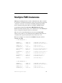
Multiple RMS Instances ................................................. 107
Declare a Dev Array of RMS Engine Instances .................. 108
Module Defining .................................................................. 109
Stacking Events and Handling Them .................................. 111
iv
RMS NetLinx Programmer’s Guide
Overview
Overview
The Resource Management Suite® products are PC server applications designed
to manage rooms and equipment. The RMS server also monitors equipment in
the rooms and sends notifications for room problems and help requests. The
RMS server allows for the logging of room and device use, errors that occur, and
offline events. The RMS server offers a variety of build-in reports for historical
and statistical analysis, as well as device monitoring through a user extensible
framework. This framework allows you to customize what devices should be
monitored, the conditions that indicates a problem or fault, and what type of
problem or fault this condition represents. The RMS server generates
notifications and routes them to different personnel when a fault condition
occurs, routing such notifications to the appropriate personnel as determined by
the notification configuration.
The RMS Software Development Kit (SDK) is composed of a series of modules
that allow users to monitor equipment errors and usage, view appointments,
display welcome images and messages, and view current appointment details
from any NetLinx compatible touch panel. Users can create presets to be
executed when a meeting starts from the actions available through
i!-ConnectLinx.
i!-ConnectLinx provides the mechanism to expose actions to the RMS server and
to manage action execution on the NetLinx system. In the RMS web pages users
can create control functions which are essentially macro sequences of
i!-ConnectLinx actions. These control function macros can be directly executed
or scheduled from the RMS web pages. i!-ConnectLinx handles these requests
and presents it to the NetLinx program for execution. See the i!-ConnectLinx
help file for details on programming i!-ConnectLinx.
RMS NetLinx Programmer’s Guide
1
Overview
2
RMS NetLinx Programmer’s Guide
System Requirements
System Requirements
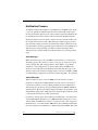
The RMS SDK is a set of NetLinx and TPDesign files that are included in your
control system programs. To utilize this SDK, you will need the following
applications installed:
NetLinx Studio 2.5 (or later)
TPDesign 4 v2.6 (or later) for G4 panels
RMS NetLinx Programmer’s Guide
3
System Requirements
4
RMS NetLinx Programmer’s Guide
Concepts
Concepts
Network Configuration
The RMS application is a client/server application where the NetLinx system acts
as the client and the RMS application server listens for connections from NetLinx
systems. NetLinx and the RMS application server communicate using TCP/IP
sockets. In order to establish communication, each NetLinx system must be able
to resolve and connect to the RMS application server. This can be accomplished
with a variety of Network configurations including local area networks (LAN),
wide area networks (WAN), and the Internet.
In order to communicate with RMS, a NetLinx system must have the RMS
modules added to its programming. The RMSEngineMod module includes the
core API and communication stack that allows NetLinx to communicate with the
RMS server.
Since each NetLinx system acts as the client, it must be configured to
communicate to the RMS server using the 'SERVER-' command in NetLinx
programming. NetLinx can accept either an IP address or a HostName for the
server. NetLinx supports DNS so if you are using a HostName, the HostName
must be registered with the DNS server that NetLinx has been configured to use.
The DNS server configuration will be picked up automatically through DHCP if
the DNS servers are registered with the DHCP server. For more information on
configuring DNS servers in NetLinx, see the NetLinx master’s instruction
manual.
Optionally, the server IP or host name can be placed in a file called ServerInfo.txt
and placed in the RMS directory of the NetLinx master's file system. If this file is
present, the RMS communication module ignores the SERVER- command and
uses the address supplied in the file. Enter the IP address or hostname on a single
line using a text editor and FTP the file to the NetLinx master. If the RMS
directory does not exist, you can create it and place the file in the directory.
By default, NetLinx and the RMS server will communicate using TCP/IP port
3839. Port 3839 is registered to AMX Resource Management Suite with IANA
(http://www.iana.org/assignments/port-numbers). This can be changed to suit
your particular facility but it must be changed in both the RMS server software
RMS NetLinx Programmer’s Guide
5
Concepts
and each NetLinx system. In the RMS server, this is accomplished through the
Configuration Wizard. In NetLinx, this is accomplished through the 'SERVER-'
command in NetLinx programming.
If using the ServerInfo.txt file, append a ":" and the port number to the server IP
address or host name.
MeetingManager 1.0 used port 9090 for communications. If you are upgrading
from MeetingManager 1.0, you may wish to continue to use port 9090. During
the upgrade process, you are prompted to change to port 3839 or continue to use
port 9090. If you change to port 3839, you need to upgrade all NetLinx systems
to use the modules from the RMS 2.0 SDK. You can use port 9090 with both
MeetingManager 1.0 and 2.0 NetLinx systems.
Once a NetLinx system has been programmed with the RMS modules and the
server's IP address or HostName, the NetLinx system automatically connects to
the RMS server.
Install Checklist
Is the RMS server's host name registered with your DNS server?
Yes
• Configure each NetLinx system to point the correct DNS server and supply the
HostName to the NetLinx programmer to use in the 'SERVER-' command. The
DNS server configuration will be picked up automatically through DHCP if the
DNS servers are registered with the DHCP server.
No
• Determine the IP address of the RMS server and supply this to the NetLinx
programmer to use in the 'SERVER-' command.
Do you want to use 3839 as the TCP/IP port for communications between Netlinx
and the RMS server?
6
Yes
• No changes need to be made in either the RMS server or NetLinx.
No
• Configure the TCP/IP in the RMS server using the Configuration Wizard and
supply the new port to the NetLinx programmer to use in the 'SERVER-'
command.
RMS NetLinx Programmer’s Guide
Concepts
Device Monitoring Framework
RMS provides device monitoring through a user extensible framework. This
framework allows you to customize what devices are monitored, the conditions
that indicate a problem or fault, and what type of problem or fault this condition
represents. RMS generates notifications when a fault condition occurs, as
determined by the notification configuration.
Each room has one or more monitored devices. Each device can be a physical
device, such as a video projector, or a logical device, like the RMS software.
However, each monitored device must be associated with a NetLinx-connected
device. In the case of a video projector, this device would be the IR card, Serial
Card or IP Socket used to communicate with the projector. The RMS software is
associated with the NetLinx master itself.
Each monitored device has one or more device parameters that represent
monitored items. For instance, monitoring lamp hours of a video projector is
accomplished through a "Lamp Hours" parameter that belongs to the "Video
Projector" device. All parameters must be associated with a device.
In order to monitor a device, the NetLinx system must register the device and one
or more parameters with RMS. For instance, monitoring of lamp hours of the
video projector is only available if the NetLinx system has added the appropriate
code. In many cases, this is as simple as adding a RMS support module.
RMS NetLinx Programmer’s Guide
7
Concepts
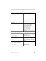
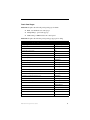
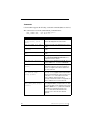
Device Values
Each monitored device has a set of values used in its description. These values
are supplied when the device is registered and consist of the following:
Device Values
Device Number
This is the device number of the device, as defined in the NetLinx
program. Devices are tracked by Device ID so this value must be
unique within the devices of a given room. For instance, you can have
multiple "1:1:0" devices as long as there is only one device with a
Device ID of "1:1:0" in the room.
Name
This is the name of device. This name is displayed on the
administrators console and readily identifies the device.
Manufacturer
This is the manufacturer of the device. If this value is not supplied
during registration, the manufacturer of the NetLinx-connected device
will be used.
Model
This is the model number of the device. If this value is not supplied
during registration, the model name of the NetLinx-connected device
will be used.
Device Type
This is the device type of the NetLinx-connected device. This might be
"NI-2000" or "NXP-TPI/4 Touch Panel". This is available for Axcess
and NetLinx devices. This information is registered automatically by
the RMS server.
Serial Number
This is the serial number of the NetLinx-connected Device. This is only
available for NetLinx devices. This information is registered
automatically by the RMS server.
Firmware Version This is the firmware version of the NetLinx-connected device. This is
only available for NetLinx devices. This information is registered
automatically be the RMS server.
Address and
Address Type
8
This is the physical address and address type for the
Netlinx-connected device. This information describes how the device
is connected to the NetLinx master. A device connected via ICSNet
will display "ICSNet" for the address type and the hardware's network
address for the address. A device connected via IP will display
"TCP/IP" for the address type and the IP address for the address.
Axcess devices will display "AXLink" for both values. This information
may be useful for diagnosing device connectivity problems.
This information is registered automatically by the RMS server.
RMS NetLinx Programmer’s Guide
Concepts
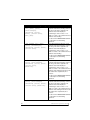
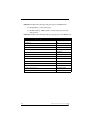
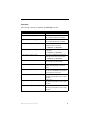
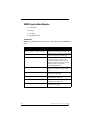
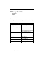
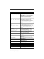
Parameter Values
Each parameter has a set of values used to determine what conditions indicate a
problem and what type of problem this condition represents. These values are
supplied when the parameter is registered and consist of the following:
Parameter Values
Name
This is the name of parameter. This name is displayed on the
RMS server console and readily identifies the parameter.
Parameters are tracked by name so this name must be unique
within the parameters of a given device. For instance, you can
have multiple "Lamp Hours" parameters as long as there is
only one "Lamp Hours" parameter per monitored device.
Parameter Type
This value indicates if this value is a number or a string. This
information is used to determine how to perform certain
operation, such as addition and comparisons between the new
and threshold values. For instance, comparing "10" and "2" as
strings results in "10" less than "2" but comparing them as
numbers results in "2" less than "10".
Value and Units
This is the current value of the parameter. Units are appended
to the value when displayed in the web console.
Threshold Value and
Comparison Operator
The threshold value is the value for which this parameter is
considered to indicate a problem or fault. The comparison
operator is used to detect when the value changes from the
un-faulted to the faulted condition. The comparison operators
"Less Than", "Less Than or Equal To", "Greater Than",
"Greater Than or Equal To", "Equal To", and "Not Equal To"
can be used for string and number parameters. The
comparison operators "Contains" and "Does Not Contain" are
primarily used for string parameters.
For example, "Lamp Hours" might have a threshold value of
1000 and any value over this would require maintenance. The
comparison operator would then be "Greater Than". When this
parameter changes from a value that is not greater than 1000
to a value that is greater than 1000, the fault status is set.
When the value changes from a value greater than 1000 to a
value not greater than 1000, the fault status is cleared. These
value are supplied during registration but can be modified by
the administrator from the RMS server console.
RMS NetLinx Programmer’s Guide
9
Concepts
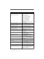
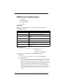
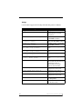
Parameter Values
Status Type
The status represents the type of problem a faulted condition
represents. Status Types include "Help Request",
"Maintenance Request", "Room Communication Error",
"Control System Error", "Network Error", "Security", and
"Equipment Usage."
For example, when "Lamp Hours" changes from an un-faulted
(not greater than 1000) to a faulted (greater than 1000), this
change represents a "Maintenance Request" status that
requires an AV technician to repair the equipment. If the
"Device Online" parameter changes from "Online" to "Offline",
this change could represent a "Security" or "Control System
Error" status.
These value are supplied during registration but can be
modified by the administrator from the RMS server
console.
Reset Flag and Reset
Value
These values determine if and how the parameter can be reset
from the RMS server console. If the Reset Flag is set, then the
administrator can reset the value remotely. When the administrator selects "Reset" from the console, the Reset Value is copied to the Value and the faulted condition is cleared. These
values are useful for parameters such as VCR "Run Time"
which would be manually reset when the VCR is cleaned.
Minimum and Maximum
Values
These values are used to restrict the range of the threshold
and reset values that the administrator can enter on the
RMS server console. These values would be used when the
parameter represents a value with a bounded range, such as a
Volume Level.
Enumeration List
This value is used to restrict the range of the threshold and
reset values that the administrator can enter on the
RMS server console. This value would be used when the
parameter represents a value with a bounded list, such as a
list containing the values Power On and Power Off.
All parameters must be registered by the NetLinx system. The administrator
cannot add parameters from the RMS console. The administrator can modify
Threshold Value, Comparison Operator, and Status Type for any parameter. This
provides the administrator with the ability to set their own thresholds and
re-classify messages based on their facility. For instance, an administrator can set
the Video projector's "Lamp Hours" threshold to the expected lamp life of a
newly replaced lamp or change the "Device Communicating" parameter from a
"Control System Error" to a "Security" status if the projector is in danger of being
stolen.
10
RMS NetLinx Programmer’s Guide
Concepts
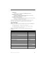
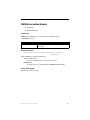
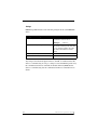
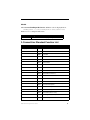
Status Types
RMS supports the following status types for device monitoring: "Help Request",
"Maintenance Request", "Room Communication Error", "Control System Error",
"Network Error", "Security", and "Equipment Usage."
While there are no firm rules for what these status types mean and how they are
used, AMX provides the following description of each status type and
recommends that your usage is consistent with these descriptions.
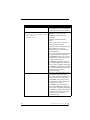
Status Types
Help Request
A user generated help request such as a help button on the
touch panel.
Maintenance Request
A user or monitored equipment generated maintenance
request. Maintenance issues would include items that
require a technician to visit the room.
Room Communication Error
A loss of communication between the room and the
RMS server.
Control System Error
Any error that represents a control system error, such as an
offline device or loss of communication with a device.
Network Error
Any network related error. These would most commonly be
associated with loss of communication with devices that
communicate via IP.
Security
Any security related issue. It might be appropriate to
classify issues that might normally be classified as Control
System or Network errors as Security issues instead. This
might include a touch panel going offline or loss of
communication with a projector depending on the physical
security of these devices.
Equipment Usage
Any issue that does not require repair or maintenance and
that is mainly used for status.
RMS NetLinx Programmer’s Guide
11
Concepts
Notification Process
As NetLinx sends parameter updates to the RMS server, the RMS server checks
to see if the parameter's threshold value has been reached. This comparison is
made by checking the previous value of the parameter against the threshold and
by checking the new version of the parameter against the threshold using the
threshold comparison operator. If the comparison for the old value is False and
the comparison for the new value is True, then the parameter triggers an Alert
message. If the comparison for the old value is True and the comparison for the
new value is False, then the parameter triggers an Advise message. Therefore an
Alert message is generated when a parameter reaches its threshold, and an
Advise message is generated when a parameter returns to its normal operating
range.
Alert Messages
When an Alert message occurs, the RMS server first checks to see if message
should be logged to the various log services. A message is created for each log
service using the Log Text of the parameter's Alert template, or the default
template if a custom template has not been assigned. Next, the RMS server
checks for any notifications in the Notification List matching the group, room,
and status type for the parameter and dispatch any messages via SMTP or SNPP
as needed using the appropriate text from the template assigned to the parameter.
Advise Messages
When an Advise message occurs, the RMS server first checks to see if the
parameter is configured for sending Advise messages. If not, no messages are
sent and no Log entries are created. If the parameter has been configured for
Advise messages, the message is logged and dispatched via SMTP an SNPP as
described above. However, the Advise template assigned to the parameter, or the
default Advise template if no template has been assigned to the parameter, is used
to generate the text for the log entries and messages.
For instance, if the previous value for Projector Lamp Hours is 999 and the new
value is 1001 and the threshold is set to 1000 and the threshold operator is set as
"Greater Than", the RMS server checks to see if the previous value compared to
the threshold, i.e. 999 is Greater than 1000 is False, has a different result than the
new value compared to the threshold, i.e. 1001 is Greater than 1000 is True. This
12
RMS NetLinx Programmer’s Guide
Concepts
change results in an Alert message being logged using the RMS logging settings.
Also, a message is sent to all users registers for a notification matching the
parameters group, room and status type.
If the Lamp Hours changes from 1001 to 999, the RMS server triggers an Advise
message. If the parameter is configured to send Advise messages, the message is
sent to the log and to all users registered for a notification matching the
parameters group, room, and status type.
RMS NetLinx Programmer’s Guide
13
Concepts
14
RMS NetLinx Programmer’s Guide
Getting Started
Getting Started
In order to monitor devices from an RMS system, you will need to add
programming to your NetLinx project. Only the devices and parameters that you
register from NetLinx can be monitored; the administrator cannot add parameters
from the RMS console.
While all of the device monitoring programming can be done manually, RMS
CodeCrafter can generate code for your project. From this program, you can
enter the information for the device monitoring and then generate an Include
(AXI) file. The Include (AXI) file contains the necessary code to register
monitored devices. Once the Include file is created, you need to include this file
in your main program with an #INCLUDE statement and make sure the RMS
device is defined. Also, you need to add code to set the values of any custom
parameters.
If you're upgrading an existing MeetingManager 1.0 installation, and
used the Device Monitoring Worksheet to generate your RMSMain
file, please reference Migrating from The Device Monitoring
Worksheet to RMS CodeCrafter section on page 22 for information
on how to import your worksheet into RMS CodeCrafter.
Using RMS CodeCrafter
To use RMSCodeCrafter, create a new RMSCodeCrafter project by opening the
program from the AMX Resource Management Suite > RMSCodeCrafter
Program Folder. For details on operating the program, see the
RMSCodeCrafter help file.
The RMS SDK consists of a series of modules to simplify device monitoring
programming. Device monitoring modules handle the registration of devices and
parameters, and keeping track of lamp hours and transport run time. In most
cases, adding device monitoring is achieved by selecting the appropriate device
monitoring module and adding code to inform the module of important device
changes. The RMS support modules register and monitor the following
parameters:
Basic Device (RMSBasicDeviceMod):
Device Online/Offline, Power, Communication Status for Serial devices, Control
Failure (Optional), IP Address of Socket-based devices.
RMS NetLinx Programmer’s Guide
15
Getting Started
Projector (RMSProjectorMod):
Device Online/Offline, Power, Lamp Hours, Communication Status for Serial
devices, Control Failure (Optional), IP Address of Socket-based devices.
Transport (RMSTransportMod):
Device Online/Offline, Power, Run Time, Communication Status for Serial
devices, Control Failure (Optional), IP Address of Socket-based devices.
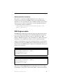
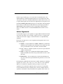
Slide Projector (RMSSldProjMod):
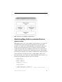
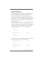
Device Online/Offline, Power, Lamp Hours
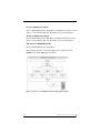
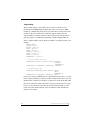
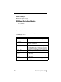
The following diagram is a visual description of the architecture of the
RMSMain.axi and the RMS support modules:
FIG. 1 Architecture of The RMSMain.axi And The RMS Support Modules
16
RMS NetLinx Programmer’s Guide
Getting Started
Interfacing with the RMS SDK
Once you have used RMS CodeCrafter to generate the device monitoring code
for your system, you will need to communicate device status to the RMS support
modules.
First, you will need to notify RMS when the system power is turned on and off.
To notify RMS when the system power is ON, call this function:
RMSSetSystemPower(TRUE)
To notify RMS when the system power is turned off, call this function:
RMSSetSystemPower(FALSE)
Next, you will need to notify RMS when device power is turned on and off. If
you are using an AMX Comm module to communicate to your device, the RMS
support modules will automatically communicate with the Comm module to
determine power status. If you are using a power sensing device to monitor power
and the power sending status appears on channel 255 of the real device, the RMS
support modules will automatically detect power status. To notify RMS when the
device power is ON, call this function:
RMSSetDevicePower(DeviceIdentifier,TRUE)
Where DeviceIdentifier is the identifier for the real device, such as
dvProj.
To notify RMS when the device power is OFF, call this function:
RMSSetDevicePower(DeviceIdentifier,FALSE)
Where DeviceIdentifier is the identifier for the real device, such as
dvProj.
For projectors, you will need to notify RMS when the lamp hours changes If your
projector does not support a lamp hours command, you need to make sure you
notify RMS of the projector power using RMSSetDevicePower(). The
RMSProjectorMod module will estimate lamp hours using projector power, if
you are using an AMX Comm module to communicate to your device, the
RMSProjectorMod will communicate with the Comm module to determine lamp
hours automatically.
If your projector supports a lamp hours command, it is recommended you add
code to poll and parse lamp hours. Once you have obtained lamp hours from your
projector, notify RMS by calling this function:
RMSSetLampHours(DeviceIdentifier,Value)
RMS NetLinx Programmer’s Guide
17
Getting Started
Where DeviceIdentifier is the identifier for the real device, such as
dvProj, and Value is the lamp hour's value.
For transport devices, you will need to notify RMS when the transport state
changes. If you are using an AMX Comm module to communicate to your
device, the RMSTransportMod will communicate with the Comm module to
determine transport state automatically. If you are using an AMX system call
with no feedback offset, i.e. FIRST is 0, RMSTransportMod will communicate
with the SYSTEM_CALL to determine transport state automatically.
To notify RMS of the transport state for a custom transport implementation, use
this function:
RMSSetTransportState(DeviceIdentifier,State)
Where DeviceIdentifier is the identifier for the real device, such as
dvVCR, and State is the transport state: Play=1, stop-2, Pause=3,
FFwd=4, Rew=5, SrchFwd=6, SrchRev=7, Record=8.
For serial devices, including, RS232 and IP controlled devices, you need to add
some polling commands to these device in order to allow the RMS support
module to properly report the Device Communicating parameter. The
RMSBasicDeviceMod, RMSProjectorMod and RMSTransportMod expect to
receive a string from the device every 30 seconds. If a string is not received
within the timeout period, a loss of device communication is reported to the RMS
server.
The default value for the Device Communicating timeout is 30 seconds. If this
value works fine for your device, all you need to do is add the polling for the
device. If you want to change the timeout, set the Device Communicating timeout
for a monitored device, which will in turn call RMSSetCommunicationTimeout()
to change the default timeout. The timeout time is specified in 1/10 seconds. If
you want to disable the Device Communicating parameter, set the timeout to 0.
18
RMS NetLinx Programmer’s Guide
Getting Started
Service Mode
RMS supports a service mode where no errors will be reported. Service mode is
designed to allow a technician to work on a room without causing error reports.
For instance, if a projector needs to be replaced or serviced, RMS would report
Device Not Communicating when the technician disconnected the power cable or
communication cable. To prevent this error from being reported to RMS, put
RMS in service mode using the 'SERVICE-ON' command. When the work is
completed, exit service mode using the 'SERVICE-OFF' command.
Since service mode bypasses error reporting, it represents a security problem. For
instance, in service mode no error is reported when the projector stops
communicating even if it is being disconnected by unauthorized personnel.
Therefore, service mode does not appear as a button on a touch panel. Service
mode should be implemented in an appropriate method for the facility. These
methods may include:
A button on a protected touch panel page
A button on a protected web-based touch panel page
A switched connected to an IO port on a NetLinx system accessible
only by technicians.
A key-activated switch connected to an IO port on a NetLinx system.
Device Parameter Persistence
Monitored devices and parameters are registered with RMS the first time a
NetLinx system connects to the RMS server. These devices and parameters are
stored internally in RMS. When NetLinx connects and sends device and
parameter registration, any devices and parameters that already exists in RMS are
not overwritten. This allows the administrator to change a value, such as the lamp
life threshold of a projector, and the value will not be lost even if the NetLinx
systems disconnects and reconnects.
As a result, changes to device monitoring NetLinx code will not take affect if the
changes are made to devices or parameters that already exists in RMS. For
instance, if you change the threshold value for a parameter or delete a device or
parameter and reload the NetLinx code, the new threshold will not be used and
any deleted device or parameters will still appear in RMS.
RMS NetLinx Programmer’s Guide
19
Getting Started
To clear out all monitored devices and parameters, delete the room and then add
the room back. Deleting a room from RMS deletes all associated monitored
devices and parameters from the RMS server.
Optionally, you can delete a device or a parameter from the RMS console
provided the device is not the "System" device and the parameter is not one of its
parameters.
20
RMS NetLinx Programmer’s Guide
Custom Device Monitoring Programming
Custom Device Monitoring
Programming
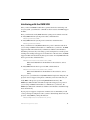
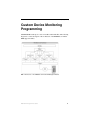
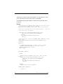
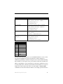
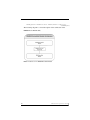
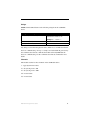
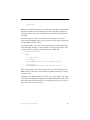
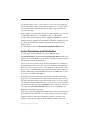
The RMS SDK is made up of a series of modules and include files. The following
diagram is a visual description of the architecture of the RMSMain.axi and the
RMS support modules:
FIG. 2 Architecture of The RMSMain.axi And The RMS Support Modules
RMS NetLinx Programmer’s Guide
21
Custom Device Monitoring Programming
RMSCommon.axi
RMSCommon.axi is an included file designed to help perform many device
monitoring tasks. This file provides device-monitoring constants, functions that
generate device monitoring SEND_COMMANDs to RMS, as well as providing a
"callback" function for important device monitoring RMS events.
In order to use this include file, your program will need to define the RMS device
and a couple of functions. The include file sends commands to and creates an
event for the RMS device, vdvRMSEngine. You must create this device in your
program. In your code, the device definition needs to be defined as:
DEFINE_DEVICE
vdvRMSEngine = 33001:1:0
The virtual device number needs to be unique and not conflict with any other
virtual device defined in your program.
RMS will notify your program when it is time to register devices and parameters
and when the administrator resets a parameter from the RMS console. RMS
sends these events to your program as a string from vdvRMSEngine. The event
processing section in this include file will process these strings, parse the
parameters and call a function in your program to notify you of the event. These
functions need to be defined in your program whether you use them or not,
otherwise the compiler will generate an error since it cannot find these functions.
The two functions you need to include are:
RMSDevMonRegisterCallback()
This function is called when RMS engine module connects to the RMS server.
Since the RMS engine module does not store any information about monitored
devices and their parameters, this information must be sent to the RMS only
when the module is connected to the server. If you want to add any custom device
monitoring code, you can register your device and parameters in this function. In
your code, the function needs to be defined as:
DEFINE_FUNCTION RMSDevMonRegisterCallback()
{
}
22
RMS NetLinx Programmer’s Guide
Custom Device Monitoring Programming
RMSDevMonSetParamCallback()
The function is called when the RMS administrator chooses "Reset" for a
parameter that can be reset on the RMS console. You can determine which
parameter was reset by checking the value of dvDPS and cName. All parameters
values are sent as a string so you will need to convert it appropriately. In your
code, the function needs to be defined as:
DEFINE_FUNCTION RMSDevMonSetParamCallback(DEV dvDPS, CHAR
cName[], CHAR cValue[])
{
}
RMS Engine module
The RMS engine module will automatically register the "System" device that is
associated with the NetLinx Master, Device ID 0:1:0. RMS will automatically
register four parameters for this device. They are "System Power," "Help
Request," "Maintenance Request", and "Service Mode." In addition, the system
will monitor room communication status for each room. These parameters
require no programming on your part for registration. However, you will need to
add support for system power. RMS registers and manages this parameter for you
but you need to notify RMS when the system power is turned On or Off. You can
do this in one of four ways:
Turn System On:
RMSSetSystemPower(TRUE)
SEND_STRING vdvRMSEngine,'POWER=1'
PULSE[vdvRMSEngine,27]
ON[vdvCLActions,1001]
Turn System Off:
RMSSetSystemPower(FALSE)
SEND_STRING vdvRMSEngine,'POWER=0'
PULSE[vdvRMSEngine,28]
ON[vdvCLActions,1002]
The last way to inform RMS utilizes the i!-ConnectLinx device. If you add the
programming to your system to allow i-ConnectLinx to control power using the
RMS NetLinx Programmer’s Guide
23
Custom Device Monitoring Programming
standard power channels and provide feedback to i!-ConnectLinx for system
power, this information will automatically be read by RMS.
See the RMS engine module definition for details about the module and its
parameters.
Example:
//This registers the dvRelay device under the name “Rack Power”
//- called in the online event for dvRelay
RMSRegisterDevice(dvRELAY,'Rack Power','AMX','NI-3000 Relay')
//This sets the parameters for the registered device - called in
//the online event for dvRelay
RMSRegisterDeviceIndexParam(dvRELAY,'Rack Power',
1,RMS_COMP_LESS_THAN,RMS_STAT_MAINTENANCE,
FALSE,0,
RMS_PARAM_SET,nRMSRackPowerRackPower,
'OFF|ON')
//This function is called from CHANNEL_EVENT [dvRELAY,0] (Relay
//on or off)
DEFINE_FUNCTION RMSSetRackPowerRackPower(INTEGER nValue)
LOCAL_VAR
CHAR bInit
{
IF (nRMSRackPowerRackPower <> nValue || bInit = FALSE)
RMSChangeIndexParam(dvRELAY,'Rack Power',nValue)
nRMSRackPowerRackPower = nValue
bInit = TRUE
}
DATA_EVENT [dvRELAY]
{
ONLINE:
{
RMSRegisterDevice(dvRELAY,'Rack Power','AMX','NI-3000
Relay')
RMSRegisterDeviceIndexParam(dvRELAY,'Rack Power',
1,RMS_COMP_LESS_THAN,RMS_STAT_MAINTENANCE,
FALSE,0,
RMS_PARAM_SET,nRMSRackPowerRackPower,
'OFF|ON')
}
OFFLINE:
RMSNetLinxDeviceOffline(dvRELAY)
}
CHANNEL_EVENT [dvRELAY,0]
{
// Channel On
24
RMS NetLinx Programmer’s Guide
Custom Device Monitoring Programming
ON:
{
SWITCH (CHANNEL.CHANNEL)
{
CASE 1:
RMSSetRackPowerRackPower(1)
break
}
}
// Channel Off
OFF:
{
SWITCH (CHANNEL.CHANNEL)
{
CASE 1:
RMSSetRackPowerRackPower(0)
break
}
}
}
RMS NetLinx Programmer’s Guide
25
Custom Device Monitoring Programming
RMS Device Monitoring Support Modules
Next, you will want to consider adding RMS device monitoring support modules
for monitoring basic devices. Adding these support modules will handle most of
the monitoring requirements for these devices. RMS offers the following support
modules:
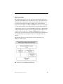
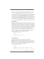
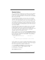
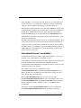
RMSBasicDeviceMod
This module monitors basic devices. For each device, this module will register
and monitor online/offline status, communication status, control failure, and
power. Communication status is registered only if the device is a two-way device.
This includes serial devices and IP sockets. Control failure is registered only if
enabled via a SEND_COMMAND, and is based on the ability to control power.
If the device is an IP-based device, the IP address NetLinx is communicating
with is also registered with RMS.
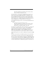
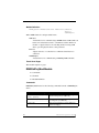
The following diagram is a visual description of the architecture of the
RMSBasicDeviceMod module:
FIG. 3
26
Architecture of The RMSProjectorMod Module
RMS NetLinx Programmer’s Guide
Custom Device Monitoring Programming
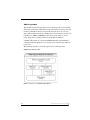
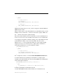
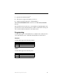
RMSProjectorMod
This module monitors projectors. For each projector, this module will register
and monitor online/offline status, communication status, control failure, power,
and lamp hours. Communication status is registered only if the device is a twoway device. This includes serial devices and IP sockets. Control failure is
registered only if enabled via a SEND_COMMAND, and is based on the ability
to control power. If the device is an IP-based device, the IP address NetLinx is
communicating with is also registered with RMS. Lamp hours are determined by
counting the time that the device's power is On. However, this module can also
accept the value of lamp hours as a SEND_COMMAND when you have a
projector that can provide lamp hours. Since this module registers lamp hours, it
is recommended only for use with devices that have lamps that need to be
replaced.
The following diagram is a visual description of the architecture of the
RMSProjectorMod module:
FIG. 4 Architecture of The RMSTransportMod Module
RMS NetLinx Programmer’s Guide
27
Custom Device Monitoring Programming
RMSTransportMod
This module monitors transport devices. For each transport device, this module
will register and monitor online/offline status, communication status, power, and
run time. Communication status is registered only if the device is a two-way
device. This includes serial devices and IP sockets. Control failure is register only
if enabled via a SEND_COMMAND, and is based on the ability to control
power. If the device is an IP-based device, the IP address NetLinx is
communicating with is also registered with RMS. Run time is determined by
counting the time that the device is in a transport state other than stop while the
power is on.
The following diagram is a visual description of the architecture of the
RMSTransportMod module:
FIG. 5 Architecture of The RMSSldProjMod Module
28
RMS NetLinx Programmer’s Guide
Custom Device Monitoring Programming
RMSSldProjMod
This module monitors slide projectors. For each projector, this module will
register and monitor online/offline status, power, and lamp hours. Lamp hours are
determined by counting the time that the device's power is On.
The following diagram is a visual description of the architecture of the
RMSSldProjMod module:
FIG. 6 Architecture of The RMSBasicDeviceMod Module
RMS NetLinx Programmer’s Guide
29
Custom Device Monitoring Programming
Programming
These modules require a virtual device, the real device of the device to be
monitored, and the RMS Engine module's device. If you are using an AMX
module for communicating with a device, the virtual device used for the Comm
module can be passed to the device monitoring support module. Since the
support modules are written to listen for the messages for the particular device
types they support, no additional programming is needed. Simply define the
devices, add the module, and pass the device numbers as module parameters. An
example:
DEFINE_DEVICE
dvSlide = 96:1:0
dvVPROJ = 5001:1:0
dvVCR = 5001:2:0
dvSWT = 5001:3:0
vdvVPROJ = 33001:1:0
vdvVCR = 33002:1:0
vdvSWT = 33003:1:0
vdvRMSEngine = 33003:1:0
// Projector Monitoring Code
DEFINE_MODULE 'RMSProjectorMod' mdlProj1(vdvVPROJ,
dvVPROJ,
vdvRMSEngine)
DEFINE_MODULE 'COMM_XXXXX' COMM(dvVPROJ, vdvVPROJ)
// VCR Monitoring Code
DEFINE_MODULE RMSTransportMod' mdlVCR1 (vdvVCR,
dvVCR,
vdvRMSEngine)
DEFINE_MODULE 'COMM_XXXXX' COMM(dvVCR, vdvVCR)
If you are not using an AMX module for communicating with a device, you will
need to add programming to notify the module of changes in the device state. For
the Basic Device and Projector module, you will need to notify the module when
the power is turned On or Off. Optionally, if you have polled for projector lamp
hours, you can provide this value directly. For the transport module, you will
need to notify the module when the power is turned On or Off and when the
transport state changes.
30
RMS NetLinx Programmer’s Guide
Custom Device Monitoring Programming
Notify Modules
Turn Power On:
RMSSetDevicePower(dvProj,TRUE)
SEND_STRING vdvVPROJ,'POWER=1'
PULSE[vdvVPROJ,27]
ON[vdvVPROJ,255]
Turn Power Off:
RMSSetDevicePower(dvProj,FALSE)
SEND_STRING vdvVPROJ,'POWER=0'
PULSE[vdvVPROJ,28]
OFF[vdvVPROJ,255]
Set Lamp Hours
RMSSetLampHours(dvProj,Value)
SEND_STRING
vdvVProj,'LAMPTIME=Value'
Set Transport State (1=Play,
2=Stop, etc…):
RMSSetTransportState(dvVCR,State)
SEND_STRING vdvVCR,
'TRANSPORT=State'
PULSE[vdvVCR,State+240]
Where State is:
1
Play
2
Stop
3
Pause
4
Fast Forward
5
Rewind
6
Search forward
7
Search Reverse
8
Record
You may notice that for power state, you can PULSE channel 27 or 28 to set the
state. Since most IR files store the power functions on these channels, no
additional programming is needed to send power state to the module when using
these channels to control power. Also, power status is monitored on channel 255
which is often linked to a power sensing device connected to an IO device. If you
are using an IO device to monitor power, the IO status should be set to report on
channel 255 of the real device. In some cases, this requires a 'SET IO LINK'
command to be sent to the real device. In these cases, simply pass the real device
RMS NetLinx Programmer’s Guide
31
Custom Device Monitoring Programming
as both the virtual and real device of the support module. However, in this case,
you cannot use SEND_STRING for notifying the module of transport state.
You may notice that for transport state, you can pulse a channel between 241-248
to set the transport state. Since AMX SYSTEM_CALLs use those channels to
store transport state, no additional programming is needed to send transport state
to the module when using a SYSTEM_CALL. In this case, simply pass the real
device as both the virtual and real device of RMSTransportMod. However, in this
case, you cannot use SEND_STRING for notifying the module of transport state.
Control Failure
When the device is IR, power status is monitored using channel 255. Axcent3's,
NXC_IRS4 cards, NXI's and NI series controllers can all provide an IO link that
enables an IO status to appear on channel 255 of the device. These modules will
watch for power attempts using channel 9, 27 or 28 and report a control failure if
the power of the device does not respond properly. Additionally, the module will
monitor channel 254, used as a power fail channel when using the 'PON'
commands, and report control failure conditions when this channel is on. This
functionality must be enabled via the RMSEnablePowerFailure() function,
defined in the RMSCommon.axi include file. For example:
DATA_EVENT[vdvRMSEngine]
{
ONLINE :
{
RMSEnablePowerFailure(dvProj)
}
}
Device Information
You may want to define the name, manufacturer, and model using
RMSSetDeviceInfo(). Device information is usually sent in a device registration
message and can only be sent when the RMS engine module connects to the
RMS server. However, if the device is monitored by a support module, the device
info message can be sent at any time. For example:
DATA_EVENT[vdvRMSEngine]
{
ONLINE :
{
RMSSetDeviceInfo(dvProj,'Name','Manufacturer','Model
Number')
RMSSetDeviceInfo(dvVCR,'Name','Manufacturer','Model Number')
32
RMS NetLinx Programmer’s Guide
Custom Device Monitoring Programming
}
}
The RMSSetDeviceInfo () is defined in the RMSCommon.axi include file.
Monitoring Source Usage
RMS can monitor source usage by using the RMSSrcUsageMod module.
RMSSrcUsageMod will track the amount of time, in minutes, a given source is
selected and logs this information to RMS when a new source is selected. This
information can be used to generate reports to determine the actual usage of a
device in a room.
Source Select
RMSSrcUsageMod monitors the selected source through
i!-ConnectLinx. i!-ConnectLinx includes 20 source selects in the standard
function list. Any standard source selected registered with i!-ConnectLinx will
automatically register in RMS by RMSSrcUsageMod. As your programming sets
the selected source on the i!-ConnectLinx device, RMSSrcUsageMod will track
the usage of the source and report it to RMS. To enable usage monitoring of a
standard i!-ConnectLinx source, simply register the source with i!-ConnectLinx
and add programming for the source select as if you were programming a button
from a touch panel:
DEFINE_EVENT
BUTTON_EVENT[vdvCLActions,1011]// VCR Select
{
PUSH:
{
// Switch the projector and switcher to select the VCR
PULSE[vdvCLActions,1011]
}
}
DATA_EVENT[vdvCLActions]
{
ONLINE:
{
// VCR Select
SEND_COMMAND vdvCLActions,"'ADD STD-1011'"
}
Additionally, you can add custom source to i!-ConnectLinx as custom actions.
Any custom action registered with i!-ConnectLinx that is named "Select …" will
RMS NetLinx Programmer’s Guide
33
Custom Device Monitoring Programming
be registered as a custom source. For instance, a custom action called "Select
Slide To Video" will register a source called "Slide To Video."
DEFINE_EVENT
BUTTON_EVENT[vdvCLActions,1]// Custom Source
{
PUSH:
{
// Switch the projector and switcher to select the Source
ON[vdvCLActions, 1]
}
}
DATA_EVENT[vdvCLActions]
{
ONLINE:
{
// VCR Select
SEND_COMMAND vdvCLActions,"'ADD ACTION-1,Select Custom
Source'"
}
To notify i!-ConnectLinx and RMSSrcUsageMod when no source is active, set
the i!-ConnectLinx status for Power Off using the standard Power Off action:
PULSE[vdvCLActions, 1002]
By default, RMS monitors a single source at a time. If a new source is selected,
the previous selected source's usage is tracked and the new source is selected.
However, if you have more that one destination in your system, such as two
projectors, this operation is not desirable. RMS can monitor each source
independently based on the status of the source select channel. To enable this
mode in RMSSrcUsageMod, call RMSSetMultiSource() with a parameter of
true. For example:
DATA_EVENT[vdvRMSEngine]
{
ONLINE :
{
RMSSetMultiSource(TRUE)
}
}
The following diagram is a visual description of the architecture of the
RMSSrcUsageMod module:
34
RMS NetLinx Programmer’s Guide
Custom Device Monitoring Programming
FIG. 7 Architecture of The RMSSrcUsageMod Module
Monitoring Many NetLinx-connected Devices
RMSNLDeviceMod
This module monitors one or more NetLinx-connected devices. For each device,
the module will register and monitor the online/offline status. This module
provides a very simple way to monitor NetLinx-connected devices. However, it
does not allow the naming of these devices. All devices registered with this
module will display their device definition for their name, for example 128:1:0,
and the manufacturer and model will be determined by the device. This module is
most useful for monitoring a large quantity of NetLinx devices where the logical
name of the device is not important, such as a bank of Input or Relay cards.
To use this module, create a device array with the NetLinx connected devices you
want monitored. Then pass this device array to the module:
DEFINE_DEVICE
dvDev1 = 5002:1:0
dvDev2 = 5002:2:0
dvDev3 = 5002:3:0
dvRMSEngine = 33001:1:0
DEFINE_VARIABLE
// RMS NetLinx Device to Monitor
VOLATILE DEV dvMonitoredDevices[]= { dvDev1, dvDev2, dvDev3 }
RMS NetLinx Programmer’s Guide
35
Custom Device Monitoring Programming
DEFINE_MODULE 'RMSNLDeviceMod' mdlNLD(dvMonitoredDevices,
vdvRMSEngine)
The following diagram is a visual description of the architecture of the
RMSNLDeviceMod module:
FIG. 8 Architecture of The RMSNLDeviceMod Module
36
RMS NetLinx Programmer’s Guide
Custom Device Monitoring Programming
Monitoring A Single NetLinx-connected Device
The RMSCommon.axi include file provides two functions that help to monitor
the Online/Offline status of a NetLinx connected device. You can use these
functions to monitor a device like a touch panel or bus box. These two functions
are:
RMSNetLinxDeviceOnline(dvDPS, cName)
RMSNetLinxDeviceOffline(dvDPS)
RMSNetLinxDeviceOnline() will register the device and the online/offline
parameter as well as set the parameter to online. This function will need to be
called in two places. Call RMSNetLinxDeviceOnline() in the
RMSDevMonRegisterCallback() function to make sure it is registered when the
RMS engine module connects to the RMS server. Also, call
RMSNetLinxDeviceOnline() when the NetLinx-connected device reports online.
RMSNetLinxDeviceOffline() updates the online/offline parameter to offline. It
only needs to be called when the NetLinx-connected device reports offline.
For example, to monitor a touch panel, add the following code:
DEFINE_DEVICE
dvTP
= 10000:1:0
DEFINE_FUNCTION RMSDevMonRegisterCallback()
{
RMSNetLinxDeviceOnline(dvTP,'Touch Panel 1')
}
DEFINE_EVENT
DATA_EVENT[dvTP]
{
ONLINE:
RMSNetLinxDeviceOnline(dvTP,'Touch Panel 1')
OFFLINE:
RMSNetLinxDeviceOffline(dvTP)
}
RMS NetLinx Programmer’s Guide
37
Custom Device Monitoring Programming
Registering Devices
The RMSCommon.axi include file provides some simple functions for
registering devices. The functions can be used in the
RMSDevMonRegisterCallback() function, called when RMS engine module
connects to the RMS server. These functions generate SEND_COMMANDs,
which you can generate manually. However, using these functions may help
eliminate syntax issues. To register a device, call this function:
RMSRegisterDevice(dvDPS, cName, cManufacturer, cModel)
This function will need to be called in two places. Call RMSRegisterDevice () in
the RMSDevMonRegisterCallback() function to make sure it is registered when
the RMS engine module connects to the RMS server. Also, call
RMSRegisterDevice () when the NetLinx-connected device reports online. This
function will automatically register the Online/Offline parameter and set this
value to Online.
The RMSRegisterDevice() function and the corresponding RMS
SEND_COMMAND that it generates will only work for devices that are
currently online. This is because RMS tracks information such as firmware
version and serial number that are only available when the device is online.
Registering Parameters
Before registering a parameter, the device with which the parameter is associated
must have been previously registered. However, if a support module RMS has
registered the device already, you do not need to re-register it. For instance, you
may want to add a parameter to the "System" device, 0:1:0. In this case, simply
register the parameter for device 0:1:0.
38
RMS NetLinx Programmer’s Guide
Custom Device Monitoring Programming
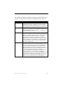
The combination of Number and String parameters types and enumeration lists
provide four unique kinds of parameters to the NetLinx program. These are:
Registering Parameters
Number Parameter Number parameters are parameters of type number with no
enumeration list. These are commonly used for values that are
programmatically available and displayed in numeric form. Examples
of number parameters are projector lamp hours and VCR run time.
String Parameter
String parameters are parameters of type string with no enumeration
list. These are commonly used for values that are programmatically
available and displayed in text form. Examples of string parameters
are help or maintenance request.
Enum Parameter
Enum parameters are parameters of type string with an enumeration
list. These are commonly used for values that are programmatically
available and displayed in text form where the text is expected to be
limited to a list. The value NetLinx sends for an enumeration
parameter needs to exist in the enumeration list. However, the
administrator will only be allowed to pick a threshold or reset value
from the enumeration list. An example of an enum parameter is the
currently selected source. The "|" character is used to separate
values in the enumeration list.
Index Parameter
Index parameters are parameters of type number with an
enumeration list and are similar to the Enum parameter. However,
these are commonly used for values that are programmatically
available numerically but displayed in text form where the text is
expected to be limited to a list. The value NetLinx sends for an
enumeration parameter must exist in the enumeration list. However,
the value sent from NetLinx represents the index into the
enumerated list instead of the actual value. An example of Enum
parameters is power. The value for power is often available
programmatically as a zero or a one but should be displayed as "Off"
or "On." This is accomplished by sending a value of zero or one to
RMS and providing an enumeration list of "Off|On" where the "|"
character is used to separate values in the enumeration list.
RMS NetLinx Programmer’s Guide
39
Custom Device Monitoring Programming
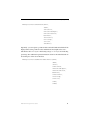
The include file provides four functions for registering these parameters. They
are:
RMSRegisterDeviceNumberParam(dvDPS,
cName,
slThreshold,
nThresholdCompare,
nThresholdStatus,
bCanReset,
slResetValue,
nInitialOp,
slInitial,
slMin,
slMax)
RMSRegisterDeviceIndexParam(dvDPS,
cName,
nThreshold,
nThresholdCompare,
nThresholdStatus,
bCanReset,
nResetValue,
nInitialOp,
nInitial,
cEnumList)
RMSRegisterDeviceStringParam(dvDPS,
cName,
cThreshold,
nThresholdCompare,
nThresholdStatus,
bCanReset,
cResetValue,
nInitialOp,
cInitial)
40
RMS NetLinx Programmer’s Guide
Custom Device Monitoring Programming
RMSRegisterDeviceEnumParam(dvDPS,
cName,
cThreshold,
nThresholdCompare,
nThresholdStatus,
bCanReset,
cResetValue,
nInitialOp,
cInitial,
cEnumList)
Optionally, you can register a parameter with a Unit field. The Units field will be
displayed next to the parameter value and threshold. You might want to use a
Unit field to add a "V" if you or monitoring voltage or "%" if you are monitoring
percentage. Two additional registration functions allow for the units field and can
be used in place of the above functions:
RMSRegisterDeviceNumberParamWithUnits(dvDPS,
cName,
cUnits,
slThreshold,
nThresholdCompare,
nThresholdStatus,
bCanReset,
slResetValue,
nInitialOp,
slInitial,
slMin,
slMax)
RMS NetLinx Programmer’s Guide
41
Custom Device Monitoring Programming
RMSRegisterDeviceStringParamWithUnits(dvDPS,
cName,
cUnits,
cThreshold,
nThresholdCompare,
nThresholdStatus,
bCanReset,
cResetValue,
nInitialOp,
cInitial)
This function will need to be called in two places. Call
RMSRegisterDevicexxxParam () in the RMSDevMonRegisterCallback()
function to make sure it is registered when the RMS engine module connects to
the RMS server. Also, call RMSRegisterDevicexxxParam () when the NetLinxconnected device reports online.
The dvDPS is the device number of the device this parameter is associated with
and cName is the name of the parameter to register.
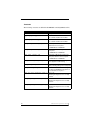
nThresholdCompare can be one of the following values:
RMS_COMP_NONE (0),
RMS_COMP_LESS_THAN (1),
RMS_COMP_LESS_THAN_EQ_TO (2),
RMS_COMP_GREATER_THAN (3),
RMS_COMP_GREATER_THAN_EQ_TO (4),
RMS_COMP_EQUAL_TO (5),
RMS_COMP_NOT_EQUAL_TO (6),
RMS_COMP_CONTAINS (7),
RMS_COMP_DOES_NOT_CONTAIN (8).
This value, along with slThreshold, nThreshold, or cThreshold, will be used to
test to see when the parameter indicates a fault as determined by the threshold
comparison changing from false to true (i.e. Value > 10).
The nThresholdStatus can be one of the following:
42
RMS NetLinx Programmer’s Guide
Custom Device Monitoring Programming
RMS_STAT_NOT_ASSIGNED (1),
RMS_STAT_HELP_REQUEST (2),
RMS_STAT_ROOM_COMM_ERR (3),
RMS_STAT_CONTROLSYSTEM_ERR (4),
RMS_STAT_MAINTENANCE (5),
RMS_STAT_EQUIPMENT_USAGE (6),
RMS_STAT_NETWORK_ERR (7),
RMS_STAT_SECURITY_ERR (8).
One of these values classifies a fault with this parameter as a Help Request,
Room Communication Error, Control System Error, Maintenance, Equipment
usage, Network Error, or Security issue.
bReset and slResetValue, nResetValue or cResetValue are used to allow the
administrator to manually reset the value. If bReset if False, then slResetValue,
nResetValue and cResetValue are ignored.
nInitialOp and slInitial, nInitial and cInitial are used to set the value of the
parameter at the time it is registered. nInitialOp can be one of the following
values:
RMS_PARAM_SET (0),
RMS_PARAM_INC (1),
RMS_PARAM_DEC (2),
RMS_PARAM_MULTIPLY (3),
RMS_PARAM_DIVIDE (4),
RMS_PARAM_UNCHANGED (6).
This eliminates the need to send a separate set parameter messages after the
parameter is registered. These constants allow you to control whether the
supplied value is set, added to, subtracted from, multiply with, divided by the
number in the database or if you simply want the value in the database to remain
the same. slInitial, nInitial and cInitial are the value with which the operation will
be performed.
slMin, slMax and eEnumList are used to limit the administrator’s selection of the
threshold and reset values. The "|" character is used to separate values in the
RMS NetLinx Programmer’s Guide
43
Custom Device Monitoring Programming
enumeration list. For Number parameters, slMin and slMax define the range the
value is expected to have. For Index and Enum, cEnumList contains the allowed
values of the parameter.
Setting Parameter Values
You can set a parameter value any time after the RMS engine module has
connected to the RMS server. Before setting the value of a parameter, the
parameter must be registered.
When registering parameters, you can supply the initial value. Therefore, you
will not need to set the parameter explicitly when it is registered, only subsequent
changes.
The include file provides four functions for setting parameter values. They are:
RMSChangeNumberParam(dvDPS, cName, nOp, slValue)
RMSChangeIndexParam(dvDPS, cName, nValue)
RMSChangeStringParam(dvDPS, cName, nOp, cValue)
RMSChangeEnumParam(dvDPS, cName, cValue)
The dvDPS is the device number of the device with which this parameter is
associated. cName is the name of the parameter to set.
nOp can be one of the following values:
RMS_PARAM_SET (0),
RMS_PARAM_INC (1),
RMS_PARAM_DEC (2),
RMS_PARAM_MULTIPLY (3),
RMS_PARAM_DIVIDE (4),
RMS_PARAM_RESET (5).
These constants allow you to control whether the supplied value is set, added to,
subtracted from, multiply with, divided by the number in the database or if you
simply want the value in the database reset to the values supplied during
parameter registration.
slValue, nValue and cValue are the current value with which the operation will be
performed. Notice that Index and Enum parameters so do not support the nOp
argument. The results of mathematical operation on an Index or Enum parameter
are undefined. Note that nValue for Index parameters are 0 based. The first
44
RMS NetLinx Programmer’s Guide
Custom Device Monitoring Programming
element in cEnum, supplied during registration, is index 0, the second element is
index 1, etc...
Most commonly, you will use the RMS_PARAM_SET (0) operation. However,
there may be instances where you want to simply allow the database to keep track
of the value and notify it of changes only. In these cases RMS_PARAM_INC (1)
and RMS_PARAM_DEC (2) are useful for adding and subtracting a value from
the current value in the database. These operations can be used with both Number
and String parameters. RMS_PARAM_INC (1) will append the string value to
the current string and RMS_PARAM_DEC (2) will remove the string value from
the current string. The results of multiple and divide on a String parameter are
undefined.
Note that values for slMin, slMax and cEnumList supplied during parameter
registration are not used to validate the value set using these functions. If a
Number parameter value falls outside the range of slMin or slMax, the value is
stored in the database and displayed. If an Enum parameter value does not appear
in the cEnum list, the value is stored in the database and displayed. If an Index
parameter value does not have an associated index in the Enum List, the value is
stored in the database and displayed as an empty value.
RMS NetLinx Programmer’s Guide
45
Custom Device Monitoring Programming
46
RMS NetLinx Programmer’s Guide
Custom "Scheduling Only" Programming
Custom "Scheduling Only"
Programming
If you wish to only utilize the scheduling features of RMS, the RMS SDK can be
optimized by only including the necessary RMS modules in your NetLinx
program.
RMS is capable of supporting multiple (up to 12) instances of
Scheduling on a single NetLinx Master. If you intend to run multiple
instances of Scheduling on a Master, then that Master should be
dedicated solely to RMS Scheduling only.
Review the following listing of RMS modules to determine which you will need
to include in your program.
Custom "Scheduling Only" Programming RMS modules
RMS Module
Required for
Scheduling
RMSEngineMod
Yes
Description
The RMSEngineMod is required to
facilitate basic communication
between the RMS server and the
NetLinx master.
i!-ConnectLinxEngineMod Yes / Dependency
The i!-ConnectLinxEngineMod is a
required dependency of the
RMSEngineMod and must be
included in the NetLinx program.
RMSUIMod
Optional
The RMSUIMod is required if a touch
panel is located inside the room to
display the room's schedule and
meeting information. Additionally, this
module supports an external display
located outside the room.
RMSWelcomeOnlyUIMod Optional
The RMSWelcomeOnlyUIMod is
required only if a touch panel is
located outside a room for an
external display of the room’s
schedule and meeting information,
and no touch panel is located inside
the room. If the RMSUIMod is
included in your program, then the
RMSWelcomeOnlyUIMod will not be
needed.
RMS NetLinx Programmer’s Guide
47
Custom "Scheduling Only" Programming
Custom "Scheduling Only" Programming RMS modules (Cont.)
48
RMSHelpUIMod
No
This module is not required for RMS
scheduling.
RMSNLDeviceMod
No
This module is not required for RMS
scheduling.
RMSProjectorMod
No
This module is not required for RMS
scheduling.
RMSTransportMod
No
This module is not required for RMS
scheduling.
RMSBasicDeviceMod
No
This module is not required for RMS
scheduling.
RMSSldProjMod
No
This module is not required for RMS
scheduling.
RMSSrcUsageMod
No
This module is not required for RMS
scheduling.
RMS NetLinx Programmer’s Guide
NetLinx Modules
NetLinx Modules
RMSEngineMod Module
Commands
Strings
Channels
Levels
Module Definition
RMS NetLinx Programmer’s Guide
49
NetLinx Modules
Commands
RMSEngineMod listens for the following commands from the vdvRMSEngine
device.
Commands and Descriptions
'SERVER-[IP/Hostname]'
Set the address of the RMS server. A port
can be specified by adding a colon (:) and a
port number to the end of the IP address or
host name. For example, you can set the
port to 10501 using this command:
'192.168.1.1:10501'.
'?SERVER'
Request the current server settings from
the module.
'CLROOT-[Folder]'
Set the root folder of i!-ConnectLinx for this
room. This command can be used to limit
the portion of the i!-ConnectLinx tree available to users when configuring room presets. This command is used when a single
NetLinx master is running more than one
instance of RMS.
'ADD DEV[DPS],[Name],[Man],[Model]
Set device info for monitored device. DPS
must be in string form (ex: '5001:1:0').
Name, Manufacturer and Model are
optional.
'ADD NPARAM[DPS],[Name],[Threshold],
[Status],[Reset],
[Initial Value],[Min],[Max]'
Add a Number parameter. DPS must be in
string form (ex: '5001:1:0').
Threshold can be any of the following:
• >=Value - Greater Than or Equal to Value
• <=Value - Less Than or Equal to Value
• ==Value -Equal to Value
• !=Value - Not Equal to Value
• <>Value - Not Equal to Value
• >Value - Greater Than Value
• <Value - Less Than Value
• (Value) - Contains Value
• )Value( - Does Not Contain Value
50
RMS NetLinx Programmer’s Guide
NetLinx Modules
Commands and Descriptions (Cont.)
Status can be any of the following:
• NONE or 1 - Not assigned
• HELP or 2 - Help Request
• ROOM or 3 - Room Communication Error
• CONT or 4 - Control System Error
• MAIN or 5 - Maintenance Error
• USAG or 6 - Equipment Usage
• NETW or 7 - Network Error
• SECU or 8 - Security Error
Reset can be any reset value or 'NO RESET'
for no reset.
Initial Value can be one of the following:
• Value - Set Value
• +=Value - Increment by Value
• -=Value - Decrement by Value
• *=Value - Multiply by Value
• \=Value - Divide by Value
• /=Value - Divide by Value
• RESET - reset the value
• NOCHANGE - do not change the value.
slMin and slMax can be any number from -2147483647 to 2147483647. slMax must be
greater than slMin. Set slMax and slMin to zero or omit the values to not impose a range.
'ADD SPARAM[DPS],[Name],[Threshold],
[Status],[Reset],
[Initial Value]'
Add a String parameter. See above in the
'ADD NPARAM' definition for a description
of all remaining arguments.
'ADD IPARAM[DPS],[Name],[Threshold],
[Status],[Reset],
[Initial Value],[Enum List]'
Add an Index parameter. Enum List is a list
of possible values separated by the '|' character. See above in the 'ADD NPARAM'
definition for a description of all remaining
arguments.
'ADD EPARAM[DPS],[Name],[Threshold],
[Status],[Reset],
[Initial Value],
[Enum List]'
Add an Enum parameter. Enum List is a
list of possible values separated by the '|'
character. See above in the 'ADD
NPARAM' definition for a description of all
remaining arguments.
RMS NetLinx Programmer’s Guide
51
NetLinx Modules
Commands and Descriptions (Cont.)
'ADD NPARAM2[DPS],[Name],[Units],
[Track Changes],
[Threshold],[Status],
[Reset],[Initial Value],
[Min],[Max]'
Add a Number parameter with unit of measurement and/or history tracking. Units is a
text string of the units to append to the
parameter value when displayed.
Track Changes can be a value of '1' to
enable or a value of '0' to disable historical
parameter value tracking.
See above in the 'ADD NPARAM' definition
for a description of all remaining
arguments.
'ADD SPARAM2-[DPS],[Name],
[Units],[TrackChanges],
[Threshold],[Status],[Reset],
[Initial Value]'
Add a String parameter with unit of measurement and/or history tracking. Units is a
text string of the units to append to the
parameter value when displayed.
Track Changes can be a value of '1' to
enable or a value of '0' to disable historical
parameter value tracking.
See above in the 'ADD NPARAM' definition
for a description of all remaining
arguments.
'ADD IPARAM2-[DPS],[Name],
[Units],[Track Changes],
[Threshold],[Status],[Reset],
[Initial Value],
[Enum List]'
Add an Index parameter with unit of measurement and/or history tracking. Units is a
text string of the units to append to the
parameter value when displayed.
Track Changes can be a value of '1' to
enable or a value of '0' to disable historical
parameter value tracking. Enum List is a list
of possible values separated by the '|'
character.
See above in the 'ADD NPARAM' definition
for a description of all remaining
arguments.
'ADD EPARAM2-[DPS],[Name],
[Units],[Track Changes],
[Threshold],[Status],[Reset],
[Initial Value],[Enum List]'
Add an Enum parameter with unit of measurement and/or history tracking. Units is a
text string of the units to append to the
parameter value when displayed.
Track Changes can be a value of '1' to
enable or a value of '0' to disable historical
parameter value tracking. Enum List is a list
of possible values separated by the '|'
character.
See above in the 'ADD NPARAM' definition
for a description of all remaining
arguments.
52
RMS NetLinx Programmer’s Guide
NetLinx Modules
Commands and Descriptions (Cont.)
'SET PARAM[DPS],[Name],[Value]'
Set a parameter value. DPS must be in
string form (ex: '5001:1:0').
Value can be one of the following:
• Value - Set Value
• +=Value - Increment by Value
• -=Value - Decrement by Value
• *=Value - Multiply by Value
• \=Value - Divide by Value
• /=Value - Divide by Value
• RESET - reset the value
• NOCHANGE - do not change the value.
'HELP-[Help Message]'
Send a help request.
'MAINT[Maintenance Message]'
Send a maintenance request.
'GET APPTS-[Date]'
Get the appointment list for Date.
'GET APPT COUNT[Month],[Year]'
Get the appointment count for Month and
Year.
'DFORMAT-DAY/MONTH'
Set Date format European format:
Day/Month/Year
'DFORMAT-MONTH/DAY'
Set Date format US format:
Month/Day/Year
'TFORMAT-12 HOUR'
Set Time format to 12 hour format:
[01-12]:[00-59] [AM,PM]
'TFORMAT-24 HOUR'
Set Time format to 24-hour (military)
format: [00-23]:[00-59]
'DEBUG-CONNECT'
Turn on debug. (including messages
related to connection to RMS server)
'DEBUG-ON’
Turn on general debug. (no connection
messages)
'DEBUG-OFF’
Turn off debug. (Default)
'VERSION’
Send version information to master debug
port (master messaging)
'SERVICE-ON’
Turn on service mode. While in service
mode, no errors will be reported.
'SERVICE-OFF’
Turn off service mode. (Default)
'ANSWERQuestionID,Flags,Answer'
Provide an answer to a question.
QuestionID and Flags should be the values
supplied from the QUESTION- string. The
Answer is a text string.
RMS NetLinx Programmer’s Guide
53
NetLinx Modules
Commands and Descriptions (Cont.)
'IGNORE SERVER TIME UPDATE'
Normally, NetLinx receives a time update
from the RMS server. This command tells
the module to ignore these time updates.
‘RESERVE[StartDate],[StartTime],[Dura
tion],[Subject],
[<MessageBody>]
Requests the RMS server to add an ac-hoc
appointment on behalf of the room.
[StartDate] should be formatted as
‘mm/dd/yyyy’
[StartTime] should be formatted as
‘hh:mm’
[Duration] is the number of minutes the
meeting should be scheduled.
[Subject] provides the meeting subject text.
[<MessageBody>] is an optional
parameter and it provides the meeting
message body text.
Upon receipt, the RMS Server will process
this request and return a confirmation or
error ‘RESERVE-‘ string. Please see the
Strings API page for further information of
the returned server response.
The ‘RESERVE’ command is supported
when using the RMS internal scheduling
system or when using Microsoft Exchange.
The ‘RESERVE’ command request will fail
if the requested appointment/meeting will
conflict with another scheduled
appointment/meeting.
‘EXTEND-[Minutes]’
Extends the current appointment/meeting
by the number of minutes provided.
Upon receipt, the RMS Server will process
this request and return a confirmation or
error ‘EXTEND-‘ string. Please see the
Strings API page for further information of
the returned server response.
The ‘EXTEND’ command is supported
when using the RMS internal scheduling
system or when using Microsoft Exchange.
The ‘EXTEND’ command request will fail if
the appointment/meeting extension will
conflict with another scheduled
appointment/meeting.
54
RMS NetLinx Programmer’s Guide
NetLinx Modules
Commands and Descriptions (Cont.)
‘ENDNOW’
End the current appointment/meeting
immediately.
Upon receipt, the RMS Server will process
this request and return a confirmation or
error ‘ENDNOW-‘ string. Please see the
Strings API page for further information of
the returned server response.
The ‘ENDNOW’ command is supported
when using the RMS internal scheduling
system or when using Microsoft Exchange.
Strings
RMSEngineMod listens for the following string from the vdvRMSEngine device.
Strings and Descriptions
'POWER=[Power State]' Set the system power state. [PowerState] should be 0
for off and 1 for on.
Example: 'POWER=1'
RMSEngineMod sends the following strings to the vdvRMSEngine device.
Strings and Descriptions
'REGISTER'
Signifies that the RMS Engine module has
connected to the RMS server. Upon receiving this
string, it is safe to register devices and parameters.
'SET PARAM[DPS],[Name],[Value]'
Set a parameter value in NetLinx. DPS will be in
string form (ex: '5001:1:0'). This string is sent when
the administrator manually resets a parameter from
the RMS console.
'ROOM NAME-[Name]
The name of the room as defined in the RMS server.
'ROOM LOCATION[Location]'
The location of the room as defined in the RMS
server.
'ROOM OWNER-[Owner]'
The owner of the room as defined in the RMS server.
'WEB SERVER[HostPort]'
The host/port of the web server where RMS is
running.
'WEB ROOT[Directory]'
The root directory of RMS on the web server where
RMS is running.
RMS NetLinx Programmer’s Guide
55
NetLinx Modules
Strings and Descriptions (Cont.)
56
'CHANGE-[Date1,Date2,
Date3,...]'
A message indicating that appointments have been
changed for the following dates. Dates are comma
separated and in the format MM/DD/YYYY.
"'APPT COUNT[Month],[Year],
'[Binary Array]"
The appointment count for Month and Year. Binary
Array is a character array that contains the counts for
each day as binary value where the first element in
the array is for the first day of Month.
"'APPT LIST-[Date],
[Total Appt],
'[Binary Appt List]"
The appointment list summary for Date. Total Appt
provides the total number of appointments for Date.
Binary Appt list is a character array with 48 entries, 1
for each ½ hour time slot for Date. The value in index
1 is the appointment index of the appointment that
occupies the first ½ hour time slot
(12:00am - 12:30 am).
"'APPT-Index,
'[Binary Data]"
The appointment data for an individual appointment.
Index is a value between 1 and Total Appt form the
'APPT LIST" string. The Binary Data is a
VARIABLE_TO_STRING encoded copy of an
appointment structure. The appointment structure is
defined as _sRMSAppointment in the include file.
This binary data can be passed to the
RMSDecodeAppointmentString() function, defined in
the include file, to convert the data to an appointment
structure.
'MESG[Flags],[Message]'
A message from the RMS console. Flags are the
message flag and Message is the text of the
message. Currently, there are no Flags defined.
'EXTEND-No'
A message indicating the current appointment could
not be extended due to a scheduling conflict.
'SERVER[Address]:[Port]'
The current RMS server address used by the
module. This is sent in response to a '/SERVER'
command.
'PRODUCT-[ID],[Name],
[Version]'
The product ID, Product name, and version of the
RMS server this module is connected to. This string
is sent upon connection to the RMS server.
'QUESTION[ID],[Flags],[Questio
ns],[Answer1],[Answer
2],[Answer3],
[Answer4]'
A question sent from the RMS server. The ID and
Flags are used to send the response. A question and
up to 4 answers may be included. All answers are
optional.
RMS NetLinx Programmer’s Guide
NetLinx Modules
Strings and Descriptions (Cont.)
‘RESERVEYES,[StartDate],[Star
tTime],[Duration],[Su
bject]
A “RESERVE’ appointment/meeting request command succeeded.
[StartDate] is formatted as
‘mm/dd/yyyy’
[StartTime] is formatted as
‘hh:mm’
[Duration] is the number of minutes the meeting is
scheduled for.
[Subject] meeting subject text.
‘RESERVENO,[StartDate],[Start
Time],[Duration],[Sub
ject],[ErrorMessage]
A “RESERVE’ appointment/meeting request command failed or was rejected by the server.
[StartDate] is formatted as
‘mm/dd/yyyy’
[StartTime] is formatted as
‘hh:mm’
[Duration] is the number of minutes the meeting is
scheduled for.
[Subject] meeting subject text.
[MessageBody] meeting message body text.
[ErrorMessage] An error message is provided
describing the reason for the failure
‘EXTEND-YES’
An “EXTEND’ current appointment/meeting request
command succeeded.
‘EXTENDNO,[ErrorMessage]’
An “EXTEND’ current appointment/meeting request
command failed or was rejected by the server. An
error message is provided describing the reason for
the failure.
‘ENDNOW-YES’
An “ENDNOW’ request command succeeded.
‘ENDNOWNO,[ErrorMessage]’
An “ENDNOW’ request command failed or was
rejected by the server. An error message is provided
describing the reason for the failure.
RMS NetLinx Programmer’s Guide
57
NetLinx Modules
Channels
9 - Toggle System Power State
27 - Set system power to ON
28 - Set system power to OFF
100 - Run Preset for Current Appointment
250 - RMS Server Online
251 - Dynamic Images Enabled
Levels
1 - Current Appointment Index
2 - Minutes Remaining In Appointment
3 - Next Appointment Index
4 - Minutes Until Next Appointment
5 - First Appointment Index
6 - Last Appointment Index
7 - Number of Appointment Remaining today
Module Definition
DEFINE_MODULE 'RMSEngineMod' mdlRMSEng(vdvRMSEngine,
dvRMSSocket,
vdvCLActions).
Where mdlRMSEng is a unique module name.
vdvRMSEngine
A virtual device for communicating to RMSEngineMod
RMSEngineMod module.
dvRMSSocket
A socket device for communicating to the RMS server.
vdvCLActions
A i!-ConnectLinx device number for executing pre-meeting presets. If
you are not using i!-ConnectLinx, pass in a value of 0:0:0.
Touch Panel Pages
This module requires no pages.
58
RMS NetLinx Programmer’s Guide
NetLinx Modules
RMSUIMod Module
Commands
Module Definition
Touch Panel Pages
Constants
Commands
RMSUIMod listens for the following commands from the vdvRMSEngine
device.
Commands and Descriptions
'DFORMAT-DAY/
MONTH'
Set Date format European format: Day/Month/Year
'DFORMAT-MONTH/
DAY'
Set Date format US format: Month/Day/Year
'TFORMAT-12 HOUR'
Set Time format to 12 hour format: [01-12]:[00-59]
[AM,PM]
'TFORMAT-24 HOUR'
Set Time format to 24-hour (military) format:
[00-23]:[00-59]
'DEBUG-ON'
Turn on debug.
'DEBUG-OFF'
Turn off debug. (Default)
'VERSION'
Send version information to master debug port (master
messaging)
Module Definition
DEFINE_MODULE 'RMSUIMod' mdlRMSUI(dvRMSEngine,
dvTp,
dvTP_Base,
dvTPWelcome,
dvTPWelcome_Base,
RMS_MEETING_DEFAULT_SUBJECT,
RMS_MEETING_DEFAULT_MESSAGE)
vdvRMSEngine:
A virtual device for communicating to RMSEngineMod
RMSEngineMod module
dvTP:
An array of main touch panel devices implementing RMSUIMod.
RMS NetLinx Programmer’s Guide
59
NetLinx Modules
dvTP_Base:
An array of main touch panel base devices addresses that correspond
with the main touch panel devices defined in the dvTP device array.
This base device array is used to capture keyboard string data events
from the main touch panels. If the RMS pages and buttons are defined
on the base device address (Port 1) then the same device array used for
the dvTP parameter can also be used for this parameter. If the RMS
pages and buttons are defined on a panel port that is not the base device
address, then this parameter will need an array of the base panel device
addresses.
dvTPWelcome:
An array of welcome touch panel devices implementing RMSUIMod.
dvTPWelcome_Base:
An array of welcome touch panel base devices addresses that
correspond with the welcome touch panel devices defined in the
dvTPWelcome device array. This base device array is used to capture
keyboard string data events from the welcome touch panels. If the
RMS welcome pages and buttons are defined on the base device
address (Port 1) then the same device array used for the dvTPWelcome
parameter can also be used for this parameter. If the RMS welcome
pages and buttons are defined on a panel port that is not the base device
address, then this parameter will need an array of the base panel device
addresses.
RMS_MEETING_DEFAULT_SUBJECT:
A character array/string that defined the default subject text for
meeting appointments scheduled form the touch panel.
RMS_MEETING_DEFAULT_MESSAGE:
A character array/string that defined the default message body text for
meeting appointments scheduled form the touch panel.
All channel and variable text numbers are defined inside the module. If you need
to change them, edit the module and re-compile the module and your program.
60
RMS NetLinx Programmer’s Guide
NetLinx Modules
Touch Panel Pages
RMSUIMod requires the following touch panel pages for dvTP:
Main - user defined room control page.
rmsSplashPage - panel start-up page
rmsRoomPage - RMS inside room control panel
RMSUIMod requires the following touch panel pop-up pages for dvTp:
Touch Panel Pop-up Pages
Popup Page
Popup Group
rmsAbout
NA
rmsCalendar
NA
rmsDoNotDisturb
NA
rmsServerOffline
NA
rmsHelpQuestion
rmsDialogs
rmsHelpRequest
rmsDialogs
rmsHelpResponse
rmsDialogs
rmsMeetingDoesNotExist
rmsDialogs
rmsMeetingEndConfirmation
rmsDialogs
rmsMeetingEndWarning
rmsDialogs
rmsMeetingExtendWarning
rmsDialogs
rmsMeetingInfo
rmsDialogs
rmsMeetingRequest
rmsDialogs
rmsMeetingRequestFailed
rmsDialogs
rmsMessage
rmsDialogs
rmsServiceRequest
rmsDialogs
rmsDoorbell
rmsDoorbell
rmsMonthSelect
rmsDropDowns
rmsYearSelect
rmsDropDowns
rmsViewSchedule1
rmsViewSchedule
rmsViewSchedule3
rmsViewSchedule
rmsViewSchedule4
rmsViewSchedule
RMS NetLinx Programmer’s Guide
61
NetLinx Modules
RMSUIMod requires the following touch panel pages for dvTPWelcome:
rmsSplashPage - panel start-up page
rmsWelcomePage - RMS outside room welcome panel (electronic
signage panel)
RMSUIMod requires the following touch panel pop-up pages for dvTPWelcome:
Touch Panel Pop-up Pages
Popup Page
62
Popup Group
rmsAbout
NA
rmsDoNotDisturb
NA
rmsServerOffline
NA
rmsMeetingDetails
rmsDialogs
rmsMeetingDoesNotExist
rmsDialogs
rmsMeetingEndConfirmation
rmsDialogs
rmsMeetingInfo
rmsDialogs
rmsMeetingRequest
rmsDialogs
rmsMeetingRequestFailed
rmsDialogs
rmsMessage
rmsDialogs
rmsViewSchedule1
rmsViewSchedule
rmsViewSchedule3
rmsViewSchedule
rmsViewSchedule4
rmsViewSchedule
RMS NetLinx Programmer’s Guide
NetLinx Modules
Constants
The following constants are defined in the RMSUIMod.axs file:
Constants
Constant
__RMS_UI_NAME__
Description
RMS module name.
This constant should not be modified.
__RMS_UI_VERSION__
RMS module version.
This constant should not be modified.
RMS_BEEP_DOORBELL_REQUEST
Panel Beep on Doorbell button push from
outside welcome touch panel.
1 = ENABLED / 0 = DISABLED
RMS_BEEP_DOORBELL_RECEIPT
Panel Beep on Doorbell signal on in room
touch panel.
1 = ENABLED / 0 = DISABLED
RMS_BEEP_PRESET_RUN
Panel Beep on Meeting Preset Execute
button press from in-room touch panel.
1 = ENABLED / 0 = DISABLED
RMS_WELCOME_PREP_TIME_MIN
Numbers of minutes before meeting start
time to prepare for next meeting.
RMS_WARN_TIME_MIN
Number of minutes before meeting ends to
display a warning dialog on the touch
panel.
RMS_EXTEND_TIME_MIN
Number of minutes to extend meeting end
time when the EXTEND meeting button is
pressed from the touch panel.
RMS_G4_USER_SCHEDULE_COLOR_0 Color 1 of 3
Alternating meeting block colors for daily
schedule.
RMS_G4_USER_SCHEDULE_COLOR_1 Color 2 of 3
Alternating meeting block colors for daily
schedule.
RMS_G4_USER_SCHEDULE_COLOR_2 Color 3 of 3
Alternating meeting block colors for daily
schedule.
RMS NetLinx Programmer’s Guide
63
NetLinx Modules
RMSWelcomeOnlyUIMod Module
Commands
Module Definition
Touch Panel Pages
Constants
Commands
RMSWelcomeOnlyUIMod listens for the following commands from the
vdvRMSEngine device.
Commands and Descriptions
'DFORMAT-DAY/MONTH' Set Date format European format: Day/Month/Year.
'DFORMAT-MONTH/DAY' Set Date format US format: Month/Day/Year.
'TFORMAT-12 HOUR'
Set Time format to 12 hour format: [01-12]:[00-59]
[AM,PM].
'TFORMAT-24 HOUR'
Set Time format to 24-hour (military) format: [00-23]:[0059].
'DEBUG-ON'
Turn on debug.
'DEBUG-OFF'
Turn off debug. (Default).
'VERSION'
Send version information to master debug port (master
messaging).
Module Definition
DEFINE_MODULE ' RMSWelcomeOnlyUIMod' mdlRMSUI(vdvRMSEngine,
dvTPWelcome,
dvTPWelcome_Base,
RMS_MEETING_DEFAULT_SUBJECT,
RMS_MEETING_DEFAULT_MESSAGE)
A virtual device for communicating to RMSEngineMod module.
dvTPWelcome:
An array of welcome touch panel devices implementing RMSUIMod.
dvTPWelcome_Base:
An array of welcome touch panel base devices addresses that correspond with
the welcome touch panel devices defined in the dvTPWelcome device array.
This base device array is used to capture keyboard string data events from the
welcome touch panels. If the RMS welcome pages and buttons are defined on
the base device address (Port 1) then the same device array used for the
dvTPWelcome parameter can also be used for this parameter. If the RMS
welcome pages and buttons are defined on a panel port that is not the base
device address, then this parameter will need an array of the base panel device
addresses.
64
RMS NetLinx Programmer’s Guide
NetLinx Modules
vdvRMSEngine:
A virtual device for communicating to RMSEngineMod module.
RMS_MEETING_DEFAULT_SUBJECT:
A character array/string that defined the default subject text for meeting
appointments scheduled form the touch panel.
RMS_MEETING_DEFAULT_MESSAGE:
A character array/string that defined the default message body text for meeting
appointments scheduled form the touch panel.
All channel and variable text numbers are defined inside the module. If you need to
change them, edit the module and re-compile the module and your program.
Touch Panel Pages
RMSWelcomeOnlyUIMod requires the following touch panel pages for dvTPWelcome:
rmsSplashPage - panel start-up page
rmsWelcomePage - RMS outside room welcome panel
(electronic signage panel)
RMSWelcomeOnlyUIMod requires the following touch panel pop-up pages for
dvTPWelcome:
Touch Panel Pop-up Pages
Popup Page
Popup Group
rmsAbout
NA
rmsDoNotDisturb
NA
rmsServerOffline
NA
rmsMeetingDetails
rmsDialogs
rmsMeetingDoesNotExist
rmsDialogs
rmsMeetingEndConfirmation
rmsDialogs
rmsMeetingInfo
rmsDialogs
rmsMeetingRequest
rmsDialogs
rmsMeetingRequestFailed
rmsDialogs
rmsMessage
rmsDialogs
rmsViewSchedule1
rmsViewSchedule
rmsViewSchedule3
rmsViewSchedule
rmsViewSchedule4
rmsViewSchedule
RMS NetLinx Programmer’s Guide
65
NetLinx Modules
Constants
The following constants are defined in the RMSWelcomeOnlyUIMod.axs file:
Constants
Constant
__RMS_UI_NAME__
Description
RMS module name.
This constant should not be modified.
__RMS_UI_VERSION__
RMS module version.
This constant should not be modified.
RMS_BEEP_DOORBELL_REQUEST
Panel Beep on Doorbell button push from
outside welcome touch panel.
1 = ENABLED / 0 = DISABLED
RMS_BEEP_DOORBELL_RECEIPT
Panel Beep on Doorbell signal on in room
touch panel.
1 = ENABLED / 0 = DISABLED
RMS_BEEP_PRESET_RUN
Panel Beep on Meeting Preset Execute
button press from in-room touch panel.
1 = ENABLED / 0 = DISABLED
RMS_WELCOME_PREP_TIME_MIN
Numbers of minutes before meeting start
time to prepare for next meeting.
RMS_WARN_TIME_MIN
Number of minutes before meeting ends to
display a warning dialog on the touch panel.
RMS_EXTEND_TIME_MIN
Number of minutes to extend meeting end
time when the EXTEND meeting button is
pressed from the touch panel.
RMS_G4_USER_SCHEDULE_COLOR_0 Color 1 of 3
Alternating meeting block colors for daily
schedule.
RMS_G4_USER_SCHEDULE_COLOR_1 Color 2 of 3
Alternating meeting block colors for daily
schedule.
RMS_G4_USER_SCHEDULE_COLOR_2 Color 3 of 3
Alternating meeting block colors for daily
schedule.
66
RMS NetLinx Programmer’s Guide
NetLinx Modules
RMSHelpUIMod Module
Commands
Module Definition
Touch Panel Pages
Commands
RMSHelpUIMod listens for the following commands from the vdvRMSEngine
device.
Commands and Descriptions
'DFORMAT-DAY/ MONTH'
Set Date format European format: Day/Month/Year
'DFORMAT-MONTH/ DAY'
Set Date format US format: Month/Day/Year
'TFORMAT-12 HOUR'
[AM,PM]
Set Time format to 12 hour format: [01-12]:[00-59]
'TFORMAT-24 HOUR'
[00-23]:[00-59]
Set Time format to 24-hour (military) format:
'DEBUG-ON'
Turn on debug.
'DEBUG-OFF'
Turn off debug. (Default)
'VERSION'
Send version information to master debug port
(mastermessaging)
Module Definition
DEFINE_MODULE 'RMSHelpUIMod' mdlRMSHelpUI(dvRMSEngine,
dvTp,
dvTP_Base)
vdvRMSEngine:
A virtual device for communicating to RMSEngineMod.
dvTP:
An array of main touch panel devices implementing RMSHelpUIMod.
dvTP_Base:
An array of main touch panel base devices addresses that correspond with the
main touch panel devices defined in the dvTP device array. This base device
array is used to capture keyboard string data events from the main touch panels.
If the RMS pages and buttons are defined on the base device address (Port 1)
then the same device array used for the dvTP parameter can also be used for
this parameter. If the RMS pages and buttons are defined on a panel port that is
not the base device address, then this parameter will need an array of the base
panel device addresses.
RMS NetLinx Programmer’s Guide
67
NetLinx Modules
All channel and variable text numbers are defined inside the module. If you need to
change them, edit the module and re-compile the module and your program.
Touch Panel Pages
RMSHelpUIMod requires the following touch panel pages for dvTP:
Main - user defined room control page.
rmsSplashPage - panel start-up page
rmsRoomPage - RMS inside room control panel
RMSHelpUIMod requires the following touch panel pop-up pages for dvTp:
Touch Panel Pop-up Pages
Popup Page
68
Popup Group
rmsAbout
NA
rmsServerOffline
NA
rmsHelpQuestion
rmsDialogs
rmsHelpRequest
rmsDialogs
rmsHelpResponse
rmsDialogs
rmsServiceRequest
rmsDialogs
rmsMessage
rmsDialogs
rmsDoorbell
rmsDialogs
RMS NetLinx Programmer’s Guide
NetLinx Modules
RMSNLDeviceMod Module
Commands
Module Definition
Commands
RMSNLDeviceMod listens for the following commands from the
vdvRMSEngine device.
Commands and Descriptions
'VERSION’
Send version information to master debug port (master
messaging)
Module Definition
DEFINE_MODULE 'RMSNLDeviceMod' mdlNLD(dvMonitoredDevices,
vdvRMSEngine)
Where mdlNLD is a unique module name.
dvMonitoredDevices
An array of NetLinx-connected devices to monitor.
vdvRMSEngine
A virtual device for communicating to RMSEngineMod module.
Touch Panel Pages
This module requires no pages.
RMS NetLinx Programmer’s Guide
69
NetLinx Modules
RMSProjectorMod Module
Commands
Strings
Channels
Module Definition
Commands
RMSProjectorMod listens for the following commands from the vdvRMSEngine
device.
Commands and Descriptions
Set device information for device monitoring.
'DEV INFO[DPS],[Name],[Man],[Model]' DPS must be in string form (ex: '5001:1:0').
70
'DEV NAME-[DPS],[Name]'
Set device name for device monitoring. DPS
must be in string form (ex: '5001:1:0').
'COMM TO-[DPS],[Timeout]'
Set the device communication timeout to
Timeout. Timeout is in 1/10-second
increments. Sending a value of zero will
disable the device communication timeout
and the registration of the device
communicating parameter.
'DEV PWR-[DPS],[State]'
Set the device power state. DPS must be in
string form (ex: '5001:1:0'). State must be 1
or 0.
'LAMP HOURS-[DPS],[Value]'
Set the projector lamp hours. DPS must be in
string form (ex: '5001:1:0').
'POWER FAIL ON-[DPS]'
Set power failure detection on. DPS must be
in string form (ex: '5001:1:0').
'POWER FAIL OFF-[DPS]'
Set power failure detection off. DPS must be
in string form (ex: '5001:1:0').
'VERSION'
Send version information to master debug
port (master messaging)
RMS NetLinx Programmer’s Guide
NetLinx Modules
Strings
RMSProjectorMod listens for the following strings from the vdvProjModule
device.
Strings and Descriptions
'POWER=[Power State]'
Set the system power state. [PowerState]
should be 0 for off and 1 for on.
'LAMPTIME=[Value]'
Set the projector lamp hours.
'MODEL=[Model]'
Set the model number.
Example: 'POWER=1'
Example: 'LAMPTIME=200'
'MANUFACTURER=[Manufacturer]' Set the manufacturer name.
Any string received from the physical device, dvProj, is an indication that the
device is communicating. As long as a string is received within the period set by
the communication timeout command, the module will notify RMS that the
device is communicating. See the communication timeout command for more
details.
Channels
The module watches for these channels on the vdvProjModule device.
9 - toggle System Power State
27 - Set system power to ON
28 - Set system power to OFF
254 - Power failure
255 - Power Status
RMS NetLinx Programmer’s Guide
71
NetLinx Modules
Module Definition
DEFINE_MODULE 'RMSProjectorMod' mdlProj1(vdvProjModule,
dvProj,
vdvRMSEngine)
Where mdlProj1is a unique module name.
vdvProjModule
A virtual device for communicating to RMSProjectorMod. This can be
the same virtual device used to communicate with an InConcert
module or a physical projector. If controlling the projector or display
using an IR device, pass the physical device to this parameter.
dvProj
A physical projector or socket device to which the projector is
connected.
vdvRMSEngine
A virtual device for communicating to RMSEngineMod module.
Touch Panel Pages
This module requires no pages.
72
RMS NetLinx Programmer’s Guide
NetLinx Modules
RMSTransportMod Module
Commands
Strings
Channels
Module Definition
Commands
RMSTransportMod listens for the following commands from the vdvRMSEngine
device.
Commands and Descriptions
'DEV INFO[DPS],[Name],[Man],
[Model]'
Set device information for device monitoring.
DPS must be in string form (ex: '5001:1:0').
'DEV NAME-[DPS],[Name]'
Set device name for device monitoring. DPS
must be in string form (ex: '5001:1:0').
'COMM TO-[DPS],[Timeout]' Set the device communication timeout to
Timeout. Timeout is in 1/10-second increments.
Sending a value of zero will disable the device
communication timeout and the registration of
the device communicating parameter.
'DEV PWR-[DPS],[State]'
Set the device power state. DPS must be in
string form (ex: '5001:1:0'). State must be 1 or
0.
'XPORT STATE[DPS],[State]'
Set the transport state. DPS must be in string
form (ex: '5001:1:0'). State should be a value 18, Play=1, Stop=2, etc…
'POWER FAIL ON-[DPS]'
Set power failure detection on. DPS must be in
string form (ex: '5001:1:0').
'POWER FAIL OFF-[DPS]'
Set power failure detection off. DPS must be in
string form (ex: '5001:1:0').
'VERSION’
Send version information to master debug port
(master messaging)
RMS NetLinx Programmer’s Guide
73
NetLinx Modules
Strings
RMSTransportMod listens for the following strings from the vdvVCRModule
device.
Strings and Descriptions
'POWER=[Power State]'
Set the system power state. [PowerState]
should be 0 for off and 1 for on.
Example: 'POWER=1'
'TRANSPORT=[Transport State]' Set the system power state. Transport
State can be 2 for Stop or any other value
for a non-stopped condition. Any value
other than 2 will enable the run-time
counter.
'MODEL=[Model]'
Set the model number.
'MANUFACTURER=[Manufacturer]' Set the manufacturer name.
Any string received from the physical device, dvVCR, is an indication that the
device is communicating. As long as a string is received within the period set by
the communication timeout command, the module will notify RMS that the
device is communicating. See the communication timeout command for more
details.
74
RMS NetLinx Programmer’s Guide
NetLinx Modules
Channels
The module watches for these channels on the vdvVCRModule device.
9 - Toggle System Power State
27 - Set system power to ON
28 - Set system power to OFF
254 - Power failure.
255 - Power Status.
The module watches for these channels on the dvVCR device.
241 - Set transport state to play.
242 - Set transport state to stop.
243 - Set transport state to pause.
244 - Set transport state to fast forward.
245 - Set transport state to rewind.
246 - Set transport state to search forward.
247 - Set transport state to search reverse.
248 - Set transport state to record.
Module Definition
DEFINE_MODULE 'RMSTransportMod' mdlVCR1(vdvVCRModule,
dvVCR,
vdvRMSEngine)
Where mdlVCR1is a unique module name.
vdvVCRModule
A virtual device for communicating to RMSTransportMod. This can be
the same virtual device used to communicate with an InConcert
module or the physical device. If using a SYSTEM_CALL for this
device, pass the physical device to this parameter.
dvVCR
A physical device or socket device to which the transport device is
connected.
vdvRMSEngine
A virtual device for communicating to RMSEngineMod module.
RMS NetLinx Programmer’s Guide
75
NetLinx Modules
Touch Panel Pages
This module requires no pages.
RMSBasicDeviceMod Module
Commands
Strings
Channels
Module Definition
Commands
RMSBasicDeviceMod listens for the following commands from the
vdvRMSEngine device.
Commands and Descriptions
Set device information for device monitoring. DPS must be
'DEV INFO[DPS],[Name],[Man] in string form (ex: '5001:1:0').
,[Model]'
76
'DEV NAME[DPS],[Name]'
Set device name for device monitoring. DPS must be in
string form (ex: '5001:1:0').
'COMM TO[DPS],[Timeout]'
Set the device communication timeout to Timeout.
Timeout is in 1/10-second increments. Sending a value of
zero will disable the device communication timeout and
the registration of the device communicating parameter.
'DEV PWR[DPS],[State]'
Set the device power state. DPS must be in string form
(ex: '5001:1:0'). State must be 1 or 0.
'POWER FAIL ON[DPS]'
Set power failure detection on. DPS must be in string form
(ex: '5001:1:0').
'POWER FAIL OFF[DPS]'
Set power failure detection off. DPS must be in string form
(ex: '5001:1:0').
'VERSION'
Send version information to master debug port (master
messaging)
RMS NetLinx Programmer’s Guide
NetLinx Modules
Strings
RMSBasicDeviceMod listens for the following strings from the vdvModule
device.
Strings and Descriptions
'POWER=[Power State]'
Set the system power state. [PowerState]
should be 0 for off and 1 for on.
'MODEL=[Model]'
Set the model number.
Example: 'POWER=1'
'MANUFACTURER=[Manufacturer]' Set the manufacturer name.
Any string received from the physical device, dvDevice, is an indication that the
device is communicating. As long as a string is received within the period set by
the communication timeout command, the module will notify RMS that the
device is communicating. See the communication timeout command for more
details.
Channels
The module watches for these channels on the vdvModule device.
9 - toggle System Power State
27 - Set system power to ON
28 - Set system power to OFF
254 - Power failure
255 - Power Status
RMS NetLinx Programmer’s Guide
77
NetLinx Modules
Module Definition
DEFINE_MODULE 'RMSBasicdeviceMod' mdBasicDev1(vdvModule,
dvDevice,
vdvRMSEngine)
Where mdlBasicDev1is a unique module name.
vdvModule
A virtual device for communicating to RMSBasicDeviceMod. This can
be the same virtual device used to communicate with an InConcert
module or a physical device. If controlling the device using an IR
device, pass the physical device to this parameter.
dvDevice
A physical device or socket device to which the virtual device is
connected.
vdvRMSEngine
A virtual device for communicating to RMSEngineMod module.
Touch Panel Pages
This module requires no pages.
RMSSldProjMod Module
Commands
Channels
Module Definition
Commands
RMSSldProjMod listens for the following commands from the vdvRMSEngine
device.
Commands and Descriptions
'DEV INFO-[DPS],[Name], Set device information for device monitoring. DPS
must be in string form (ex: '5001:1:0').
[Man],[Model]'
'DEV NAME-[DPS],[Name]' Set device name for device monitoring. DPS must
be in string form (ex: '5001:1:0').
'VERSION'
78
Send version information to master debug port
(master messaging).
RMS NetLinx Programmer’s Guide
NetLinx Modules
Channels
The module watches for these channels on the dvSldProj device.
5 - Slide Projector Power State
Module Definition
DEFINE_MODULE 'RMSSldProjMod' mdlSldProj1(dvSldProj,
vdvRMSEngine)
Where mdlSldProj1is a unique module name.
dvSldProj
A physical device to which the slide projector is connected.
vdvRMSEngine
A virtual device for communicating to RMSEngineMod module.
Touch Panel Pages
This module requires no pages.
RMS NetLinx Programmer’s Guide
79
NetLinx Modules
RMSSrcUsageMod Module
Commands
Channels
Module Definition
Commands
RMSSrcUsageMod listens for the following commands from the vdvRMSEngine
device.
Commands and Descriptions
'MULTISOURCE-[State]' Set the multi-source tracking state. State can be ON
or OFF. The default is OFF.
'VERSION’
Send version information to master debug port
(master messaging)
Channels
The module watches for these channels on the vdvConnectLinx device.
1001 - Power On
1002 - Power Off
1011 - VCR Select
1012 - HI-8 VCR Select
1013 - Umatic VCR Select
1014 - DVD Select
1015 - Laser Disc Select
1016 - TV/DVD/Cable Select
1017- Video Conference Select
1018 - Document Camera Select
1019 - Room Camera Select
1020 - Whiteboard Select
1021 - Rack Computer Select
1022 - Aux PC Select
80
RMS NetLinx Programmer’s Guide
NetLinx Modules
1023 - Aux Video Select
1024 - Slide Select
1025 - Digital Media Player Select
1041 - Music Select
1042 - CD Select
1043 - Cassette Select
1044 - DAT Select
1045 - Mini Disc Select
1046 - Aux Audio Select
1047 - Digital Audio Player Select
RMSSrcUsageMod will also listen for i!-ConnectLinx registration of custom
actions and attempt to determine if they represent source selects. Any custom
action registered with a name that starts with "Select " is assumed to be a custom
source. RMSSrcUsageMod will register this source name with the RMS server
and treat the associated channel as a source select channel. For more information
on i!-ConnectLinx programming, refer to the i!-ConnectLinx help file installed
with i!-ConnectLinx as part of the RMS SDK.
Module Definition
DEFINE_MODULE 'RMSSrcUsageMod' mdlSrcUsage(vdvRMSEngine,
vdvCLActions)
Where mdlSrcUsage is a unique module name.
vdvRMSEngine
A virtual device for communicating to RMSEngineMod module.
vdvCLActions
A i!-ConnectLinx device number for monitoring source selection.
Touch Panel Pages
This module requires no pages.
RMS NetLinx Programmer’s Guide
81
NetLinx Modules
82
RMS NetLinx Programmer’s Guide
i!-ConnectLinx
i!-ConnectLinx
i!-ConnectLinx™ is a framework that allows you to expose NetLinx™ actions
that can be utilized by other user interfaces or processes outside the NetLinx
Control System. For instance, i!-ConnectLinx can be programmed to expose
source select functions and i!-ConnectLinx compatible technologies, such as
RMS, can use this information to allow the source selects to be executed as a
scheduled event.
i!-ConnectLinx also provides a mechanism to request actions to be executed on
the NetLinx Control System. Once a process outside the NetLinx Control System
has obtained the action list, the process can then make a request to
i!-ConnectLinx to execute that action. i!-ConnectLinx handles this request and
makes this request available to the NetLinx program for execution.
i!-ConnectLinxEngineMod, is the main i!-ConnectLinx module that handles
exposing and executing action requests, see the Module section on page 95. To
support i!-ConnectLinx, you simply include this module in your program, define
your actions and write programming to support those actions. The
i!-ConnectLinxEngineMod module makes the list of actions available to other
processes, executes their requests, and provides your program with a push when
an action needs to be executed.
RMS NetLinx Programmer’s Guide
83
i!-ConnectLinx
Using i!-ConnectLinx
Little work is required to add i!-ConnectLinx to your existing NetLinx code.
i!-ConnectLinx is implemented as a NetLinx module. Adding the module
definition and all its parameters to your code is all that is required.
In order to use i!-ConnectLinx, you need to program and define a series of
actions in the NetLinx Control System. The key to the i!-ConnectLinx engine is
the virtual device, vdvCLActions. For additional information reference the
Module section on page 95. Support the actions you want executed remotely
using this virtual device.
Think of the virtual device, vdvCLActions, as a touch panel. Normally, you
write your NetLinx program to respond to certain push channels from a touch
panel; i!-ConnectLinx is exactly the same. Let’s say you want to provide the user
with the ability to play and stop a VCR. Imagine you have two touch panel
buttons that do these functions; write code that responds to the pushes:
BUTTON_EVENT[TP,1]
{
PUSH:
{
PULSE[VCR,1]
}
}
BUTTON_EVENT[TP,2]
{
PUSH:
{
PULSE{VCR,2]
}
}
(* VCR Play *)
(* VCR Stop *)
To expose these actions using i!-ConnectLinx, write the same code substituting
the touch panel device for your i!-ConnectLinx virtual device:
BUTTON_EVENT[vdvCLActions,1]
{
PUSH:
{
PULSE[VCR,1]
}
}
BUTTON_EVENT[vdvCLActions,2]
{
PUSH:
{
84
(* VCR Play *)
(* VCR Stop *)
RMS NetLinx Programmer’s Guide
i!-ConnectLinx
PULSE{VCR,2]
}
}
When the i!-ConnectLinx engine gets a request to play the VCR, i!-ConnectLinx
will "push" the button of the virtual device just like a user pushes a button on a
touch panel. There is now only one thing left to do: Tell the user which actions
are which.
In order to expose an action for execution via i!-ConnectLinx, you need to
support the programming for the action, as we have just seen, and you need to tell
i!-ConnectLinx what that action is.
To specify the name of an action, send a command to the i!-ConnectLinx virtual
device describing the name of a given channel code. To specify the names of the
actions in the above example, you would add some code like this:
DATA_EVENT[vdvCLActions]
{
ONLINE:
{
(* Setup actions *)
(* VCR Play *)
SEND_COMMAND vdvCLActions,"'ADD ACTION-1,VCR Play"
(* VCR Stop *)
SEND_COMMAND vdvCLActions,"'ADD ACTION-2,VCR Stop' "
}
Once i!-ConnectLinx receives these commands, it stores this information in an
XML file that can be used by i!-ConnectLinx compatible technologies to browse
available actions.
In addition to specifying the name of an action, you can also supply a help string
and a folder name. The help string helps a user understand the intent of the action
more clearly. The folder name allows you to organize the actions in a tree view so
that actions are more easily browsed.
RMS NetLinx Programmer’s Guide
85
i!-ConnectLinx
Standard Actions
So far, i!-ConnectLinx has handled custom actions where each action is likely to
be different from system to system. In the Using i!-ConnectLinx example on
page 84, action 1 played the VCR. However, in another system, it is very unlikely
that action 1 plays the VCR.
i!-ConnectLinx uniquely identifies each action list. Once an i!-ConnectLinx
compatible technology programs itself to execute an action on a system, it also
stores a copy of the system identifier from the action list. This identifier is sent to
i!-ConnectLinx along with this action execution request. If the action identifier
does not match the i!-ConnectLinx system that received the request, the action is
not executed. This eliminates any ambiguity that may exist, since each system’s
action 1 may be different.
i!-ConnectLinx supports standard actions. Standard actions are actions defined
by AMX and supported natively by i!-ConnectLinx. When adding actions to
i!-ConnectLinx, it is best to use the standard action if it is available. That way, the
action can be executed regardless of which system the i!-ConnectLinx
compatible technology was programmed to control.
The list of standard actions are listed in the i!-ConnectLinxStdFunctionList.xls
file. The standard actions ID are the same as the channel number used to execute
the action. For instance, VCR Select has an ID of 1011 so the programming to
support this standard action is:
BUTTON_EVENT[vdvCLActions,1011]
(* VCR Select *)
{
PUSH:
{
// Switch the projector and switcher to select the VCR
}
}
To add a standard action, look up the action ID in the Standard Function List file,
and send that in a send command to i!-ConnectLinx to tell it you want to support
that action. To change the above example to standard action:
1. Lookup VCR Play and VCR Stop in the Standard Function List.
2. Find their IDs. VCR Play is 1131, and VCR Stop is 1132.
3. Send the IDs to i!-ConnectLinx:
DATA_EVENT[vdvCLActions]
86
RMS NetLinx Programmer’s Guide
i!-ConnectLinx
{
ONLINE:
{
(* Setup actions *)
(* VCR Play *)
SEND_COMMAND vdvCLActions,"'ADD STD-1131'"
(* VCR Stop *)
SEND_COMMAND vdvCLActions,"'ADD STD-1132'"
}
Additionally, change the two BUTTON_EVENTs to trigger for channels 1131 and
1132 instead of 1 and 2.
There are other syntax’s of the add standard action command that allow you add
multiple actions at a time. The ‘&’ character can be used to signify "AND" and
the ‘-‘ character can be used to signify "through".
Since many of the standard actions are related, they can also be added by macros.
A macro is a list of one or more standard actions. In the case of a VCR, the full
set of transports are needed, not just Play and Stop. Also, if the VCR exists in the
system then there is likely a way to select the VCR as the active source.
Therefore, the "vcr" macro includes the VCR source select and the standard
transports. To load a set of actions by macro, simply send a command to i!ConnectLinx with the macro you want added. For example:
DATA_EVENT[vdvCLActions]
{
ONLINE:
{
(* Setup actions *)
(* VCR Select and Play-Record *)
SEND_COMMAND vdvCLActions,"'ADD MACRO-vcr'"
}
For a complete list of macros, see the i!-ConnectLinxStdFunctionList.xls file.
A common method for programming i!-ConnectLinx is to simply register
standard actions and respond to the actions by "DO_PUSH"ing an existing button
on the touch panel. For instance:
BUTTON_EVENT[vdvCLActions,1011](* VCR Select *)
{
PUSH:
DO_PUSH(dvTP,11) (* Button 11 on dvTP selects VCR *)
}
To make programming i!-ConnectLinx easier, the
i!-ConnectLinxStdFunctionList.xls file includes an i!-ConnectLinx Code
RMS NetLinx Programmer’s Guide
87
i!-ConnectLinx
Generator page. On this page, you can enter the i!-ConnectLinx device, the
Touch Panel device and the Touch Panel buttons for each standard action. The
code generator will create an Include (AXI) file that contains the necessary code
to register and respond to the selected actions. Optionally, the code generator can
include the DEFINE_MODULE statement for i!-ConnectLinx. Once the Include
file is created, you will need to include this file in your main program with an
#INCLUDE statement and make sure the i!-ConnectLinx and Touch Panel
devices are defined. See the i!-ConnectLinxStdFunctionList.xls file for more
details.
Action Arguments
i!-ConnectLinx supports action arguments to supply additional information with
each action. For instance, if you wanted to support an action to set the program
volume, the user needs to supply a volume level. This is accomplished using
arguments.
Each action can support zero or more arguments. Each argument can be one of
the following types:
Number – A single number from –32767 to 32767. You can define the
minimum value, maximum value, desired step, and a default value. The
user is presented with a text box in which to enter this number.
Level – Similar to a Number argument, only the user is presented with
a slider to enter the level.
String – A string. You can define the minimum length, maximum
length, and default value. The user is presented with a text box to enter
this string.
Enumeration – A list or enumeration of values from which the user
may choose. The user is presented with a drop down list to choose and
value from.
Each argument is numbered in the order they are added. Arguments are added by
using the 'ADD NARG', 'ADD LARG', 'ADD SARG', and 'ADD EARG' commands.
When an i!-ConnectLinx compatible technology requests an action with
arguments to be executed, the argument values are passed to i!-ConnectLinx.
i!-ConnectLinx then posts the argument values as levels for number and level
arguments, and strings for string and enumeration arguments. These values can
88
RMS NetLinx Programmer’s Guide
i!-ConnectLinx
be retrieved by using LEVEL_EVENTs and DATA_EVENTs in your program and
must be saved. Then, when an action request is triggered via a BUTTON_EVENT,
you can retrieve these argument values and use them (as appropriate) for the
action to be executed.
Each argument is provided an ID at the time it is added. The ID’s start at one and
are numbered sequentially to each argument as they are added. When
i!-ConnectLinx posts the argument value, it supplies the ID number as well. For
numbers and levels, this ID is the level number to which the argument is posted.
For strings and enumerations, this ID is included in the string that posts the
argument value.
For an example, see the i!-ConnectLinxStandardFunctionShell.axi file.
Action Persistence and Distribution
i!-ConnectLinx stores the supported actions in a XML file called
i!-ConnectLinx.xml located in the doc:\user\connectlinx directory. All action
information is stored in this file. i!-ConnectLinx compatible technologies retrieve
this file directly from the NetLinx Master.
It may not always be practical to keep all the i!-ConnectLinx action list files on
the NetLinx Master. For instance, in a corporate environment with 20 NetLinx
Masters in various conference rooms, a user outside the company needs to have
direct access to each NetLinx Master through the firewall in order to download
the files. Additionally, each NetLinx Master needs it’s own DNS entry, so users
do not have to remember an IP Address.
To simplify action list management, i!-ConnectLinx compatibly technologies
support an action list index file format. This index file lists the names of various
files and a URL where the file can be retrieved. This allows you to move all the
action list files from the NetLinx Masters to a web server for easy retrieval. Place
this index file in a directory called connectlinx off the root directory of the web
server and name it i!-ConnectLinx.xml. However, it can contain links to any
URL with any file name in any folder.
In the above example, the IT department might collect all the action list files and
place them in the connectlinx directory of the company’s web server. Each file
should be renamed to reflect the room that the action list is for. Then a web
developer should edit the supplied i!-ConnectLinxList.xml file to reflect the
RMS NetLinx Programmer’s Guide
89
i!-ConnectLinx
names and URL’s of each of these files and rename it to i!-ConnectLinx. Now
anyone can retrieve an action list for the company’s system by pointing to the
company’s main web address and selecting a room file from the list.
If desired, the action list index file can be viewed in an HTML browser by using
an eXtensible Style Language file. A web developer can make any adjustments to
the XSL file so the index file has the look of the company’s web site when
viewed in an HTML browser. A sample XSL file, i!-ConnectLinxList.xsl, is
supplied with i!-ConnectLinx and should be placed in the same directory on the
web server as the index file.
The URL contained in the index file can point to an additional index file to allow
for tree style navigation. For instance, the main file might list cities where the
company has offices, which point to an index file for each city. Each city index
file might contain a list of buildings and point to building index files. Then each
building index file contains the list of rooms in that building and points to the
actual action list for each room.
International Issues / Localization
Localization is the process by which an application is adapted to a locale, and
describes a user’s environment or geographical location.
i!-ConnectLinx provides the standard action name, help string, and folder names
for all the standard actions. This information is built directly into the
i!-ConnectLinx module. If English is not the primary language for the room, the
standard action text can be changed.
The standard action text can be stored in a file called
i!-ConnectLinxStdText.xml located in the doc:\user\connectlinx directory.
When a standard action is added, the text from this file is used for the action
name, the help string and folder names.
The i!-ConnectLinxStdText.xml can be created in two ways. The
i!-ConnectLinxStdTextTemplate.xml file can be altered directly and saved as
i!-ConnectLinxStdText.xml in the doc:\user\connectlinx directory. However,
this file is difficult to edit in a standard text editor so an XML file editor is
recommended.
Alternatively, the i!-ConnectLinxStdText.xml file can be created using the
i!-ConnectLinxEngineStdTextWriter.axs file. To change the language:
90
RMS NetLinx Programmer’s Guide
i!-ConnectLinx
1. Open this file in NetLinx Studio™.
2. Alter the text to support the language you choose.
3. Compile and download this file to a NetLinx Master.
The i!-ConnectLinxStdText.xml is written out to the doc:\user\connectlinx
directory.
Once this file has been created once, it can be FTP’d to the NetLinx Master and
placed in the doc:\user\connectlinx directory. When i!-ConnectLinx starts up, the
text is read from this file and used for all standard actions.
Programming
i!-ConnectLinx appears on the NetLinx bus as a NetLinx device. This device has
1 port with channels, levels, commands and strings like most other devices.
Channels
i!-ConnectLinx supports the following channels:
i!-ConnectLinx Channels
Channel
Description
All
Action to be executed for this action ID.
Levels
i!-ConnectLinx supports the following levels:
i!-ConnectLinx Levels
Level
Description
All
Action number and level arguments
RMS NetLinx Programmer’s Guide
91
i!-ConnectLinx
Commands
i!-ConnectLinx supports the following out-bound commands (Master to device).
The commands are sent in the standard Send_Command format:
SEND_COMMAND dvMP, "'SET ROOM NAME-Tesla'"
SEND_COMMAND dvMP, "'ADD MACRO-vcr'"
i!-ConnectLinx Commands
'SET ROOM INFO-[Room Name],
[Room Location], [Room
Owner]'
Sets the room name, room location, and room
owner to be displayed in the action list file.
'SET ROOM NAME-[Room Name]' Sets the room name to be displayed in the action
list file.
92
'SET ROOM LOCATION-[Room
Location]'
Sets the room location to be displayed in the action
list file.
'SET ROOM OWNER-[Owner
Name]'
Sets the room owner to be displayed in the action
list file.
'ADD MACRO-[Macro Name]'
Adds a group of standard actions.
See i!-ConnectLinxStdFunctionList.xls for a
complete list of macro names.
'ADD STD-[ID]-[ID]&[ID]'
Adds one or more standard actions by ID. The ‘&’ is
used for "AND" and ‘-‘ is used for "THROUGH".
'ADD FOLDER-[Folder Name],
[Parent]'
Adds a folder to the action list. The parent specifies
which parent folder the new folder is added to. If
parent is not supplied, this folder is added to the
root of the action list.
'ADD ACTION[ID],[Action],[Help
String],[Folder]'
Adds an action. The ID and Action are required.
The Help String appears in the action list file to
help the user determine this action’s function more
clearly. The Folder is the folder in which this
action is added to, and must have been
previously created. If the folder is not supplied, the
action is added to the root of the action list.
'ADD NARG-[Action],[Arg
Name],[Min],[Max],[Step,]
[Default]'
Adds a number argument to Action. The Arg
Name (Argument Name) is required. The Min and
Max define the limits for this argument in the range
–32767 to 32767. The Step defines the minimum
step between increments/decrements. The
Default value defines the initial value this
argument is set to when the user edits this
argument.
RMS NetLinx Programmer’s Guide
i!-ConnectLinx
i!-ConnectLinx Commands (Cont.)
'ADD LARG-[Action],[Arg
Name],[Min],[Max],[Step],
[Default]'
Adds a level argument to Action. The Arg Name
(Argument Name) is required. The Min and Max
define the limits for this argument in the range –
32767 to 32767. The Step defines the minimum
step between increments/decrements. The
Default value defines the initial value this argument is set to when the user edits this argument.
Adds a string argument to Action. The Arg Name
'ADD SARG-[Action],[Arg
Name],[Min],[Max],[Default] (Argument Name) is required. The Min and
Max define the min and max length of the string.
'
The Default value defines the initial value this
argument is set to when the user edits this
argument.
'ADD EARG-[Action],
[Arg
Name],[Default],[Enum1],
[Enum2]...'
Adds an enum argument to Action. The Arg
Name (Argument Name) is required. The Default
value defines the initial value this argument is set to
when the user edits this argument. Enum1,
Enum2,… define the available choices for the
argument.
'GET NODE[Name],[Start],[End]'
Get the node description for Name including
children from Start to End. Returns a PARENT
string and multiple CHILD strings.
'GET ACTION-[Name]'
Get the action description for Name. Returns
ACTION string and multiple argument strings
(NARG, LARG, SARG and EARG).
'GET UUID'
Get the UUID for this i!-ConnectLinx. Returns a
UUID string.
'GET ROOM INFO'
Get the room info for this i!-ConnectLinx. Returns
ROOM NAME, ROOM LOCATION and, ROOM
OWNER strings.
'GET ROOM NAME'
Get the room info for this i!-ConnectLinx. Returns a
ROOM NAME string.
'GET ROOM LOCATION'
Get the room info for this i!-ConnectLinx. Returns a
ROOM LOCATION string.
'GET ROOM OWNER'
Get the room info for this i!-ConnectLinx. Returns a
ROOM OWNER string.
'DEBUGON'
Turns on debug.
'DEBUGOF'
Turns off debug. (Default)
'RESET'
Resets the action list.
'VERSION'
Sends version information to Master debug port
(Master messaging).
RMS NetLinx Programmer’s Guide
93
i!-ConnectLinx
Strings
i!-ConnectLinx supports the following in-bound string (device to Master).
i!-ConnectLinx Strings
String
Description
"'ARG[Argument ID]-[Argument String]'" Argument String for string and
enum arguments for an action
executed soon.
'PARENT-[Name],[Child Count],[Parent]' Describes a parent node. Returned
by GET NODE command.
94
'CHILD[Child#]-[Name],
[ChildCount],[Parent]'
Describes a child of a node.
Returned by GET NODE command.
'ACTION-[ID],[Action],
[Help String],[Folder]'
Describes an action. Returned by
GET ACTION command.
'NARG-[Action],[Arg Name],
[Min],[Max],[Step,][Default]'
Describes a number argument to
Action.
'LARG-[Action],[Arg Name],
[Min],[Max],[Step],[Default]'
Describes a level argument to
Action.
'SARG-[Action],[Arg Name],
[Min],[Max],[Default]'
Describes a string argument to
Action.
'EARG-[Action],[Arg Name],
[Default],[Enum1],[Enum2]...'
Describes an enum argument to
Action.
'UUID-[UUID]'
Provides the UUID for this
i!-ConnectLinx. This ID can be used
to identify this instance of
i!-ConnectLinx from all other
instances of i!-ConnectLinx.
'ROOM NAME-[Room Name]'
Provide the room name as
displayed in the action list file.
'ROOM LOCATION-[Room Location]'
Provides the room location as
displayed in the action list file.
'ROOM OWNER-[Owner Name]'
Provides the room owner as
displayed in the action list file.
'FILE WRITE'
Notification that the i!-ConnectLinx
file is being written.
'FILE SAVED'
Notification that the i!-ConnectLinx
file is has been saved.
RMS NetLinx Programmer’s Guide
i!-ConnectLinx
Module
The i!-ConnectLinxEngineMod Module definition code is displayed below.
DEFINE_MODULE 'i!-ConnectLinxEngineMod' mdlCL(vdvCLActions)
Where mdlCL is a unique module name.
i!-ConnectLinxEngineMod Module Parameter
vdvCLActions
A virtual device number for programming NetLinx actions.
i!-ConnectLinx Standard Function List
i!-ConnectLinx Standard Function List
Category
ID
Action
System Controls
1001
Power On
1002
Power Off
1011
Select VHS
1012
Select Hi-8
1013
Select Umatic
1014
Select DVD
1015
Select Laser Disc
1016
Select TV-DSS-Cable
1017
Select Video Conference
1018
Select Document Camera
1019
Select Room Camera
1020
Select Whiteboard
1021
Select Rack Computer
1022
Select Aux PC Input
1023
Select Aux Vid Input
1024
Select Slide (slide to video)
1025
Select Digital Media Player
1041
Select Music (AM/FM Tuner or DSS)
RMS NetLinx Programmer’s Guide
95
i!-ConnectLinx
i!-ConnectLinx Standard Function List (Cont.)
Category
ID
Action
System Controls
1042
Select CD Player
1043
Select Cassette
1044
Select DAT
1045
Select Minidisc
1046
Select Aux Audio Input
1047
Select Digital Audio Player
1061
Lights All Off
1062
Lights All On
1063
Lights Meeting Mode
1064
Lights Presentation Mode
1065
Lights Conference Mode
1071
Program Mute
1072
Program Unmute
1073
Program 0%
1074
Program 25%
1075
Program 50%
1076
Program 75%
1077
Program 100%
1078
Program Set Volume
1081
Speech Mute
1082
Speech Unmute
1083
Speech 0%
1084
Speech 25%
1085
Speech 50%
1086
Speech 75%
Lighting
Room Volume
Speech Volume
96
RMS NetLinx Programmer’s Guide
i!-ConnectLinx
i!-ConnectLinx Standard Function List (Cont.)
Category
ID
Action
Speech Volume
1087
Speech 100%
1088
Speech Set Volume
1091
Screen Up
1092
Screen Down
1093
Drapes Open
1094
Drapes Close
1095
Blinds Open
1096
Blinds Close
1097
Lift Up
1098
Lift Down
1101
Display Power On
1102
Display Power Off
1103
Display Picture Mute
1104
Display Picture Unmute
1105
Display Picture Mute Toggle
1131
VCR Play
1132
VCR Stop
1133
VCR Pause
1134
VCR Fast Forward
1135
VCR Rewind
1136
VCR Search Fwd
1137
VCR Search Rev
1138
VCR Record
1161
Hi-8 Play
1162
Hi-8 Stop
Screen
Drapes
Blinds
Lift
Video Projector/Display
VCR - VHS
VCR - Hi-8
RMS NetLinx Programmer’s Guide
97
i!-ConnectLinx
i!-ConnectLinx Standard Function List (Cont.)
Category
ID
Action
VCR - Hi-8
1163
Hi-8 Pause
1164
Hi-8 Fast Forward
1165
Hi-8 Rewind
1166
Hi-8 Search Fwd
1167
Hi-8 Search Rev
1168
Hi-8 Record
1191
Umatic Play
1192
Umatic Stop
1193
Umatic Pause
1194
Umatic Fast Forward
1195
Umatic Rewind
1196
Umatic Search Fwd
1197
Umatic Search Rev
1198
Umatic Record
1221
DVD Play
1222
DVD Stop
1223
DVD Pause
1224
DVD Skip Forward
1225
DVD Skip Back
1226
DVD Search Fwd
1227
DVD Search Rev
1228
DVD Go To Track
1229
DVD Go To Chapter
1230
DVD Go To Time
1251
LDP Play
VCR - Umatic
DVD
Laser Disc Player
98
RMS NetLinx Programmer’s Guide
i!-ConnectLinx
i!-ConnectLinx Standard Function List (Cont.)
Category
ID
Action
Laser Disc Player
1252
LDP Stop
1253
LDP Pause
1254
LDP Skip Forward
1255
LDP Skip Back
1256
LDP Search Fwd
1257
LDP Search Rev
1258
LDP Go To Track
1259
LDP Go To Chapter
1260
LDP Go To Time
1281
TV Channel Up
1282
TV Channel Down
1283
TV Go To Channel
1291
TV Keypad 0
1292
TV Keypad 1
1293
TV Keypad 2
1294
TV Keypad 3
1295
TV Keypad 4
1296
TV Keypad 5
1297
TV Keypad 6
1298
TV Keypad 7
1299
TV Keypad 8
1300
TV Keypad 9
1301
TV-ABC
1302
TV-CBS
1303
TV-NBC
TV - DSS - Cable
RMS NetLinx Programmer’s Guide
99
i!-ConnectLinx
i!-ConnectLinx Standard Function List (Cont.)
Category
ID
Action
TV - DSS - Cable
1304
TV-PBS
1305
TV-FOX
1306
TV-UPN
1307
TV-WB
1308
TV-CNBC
1309
TV-CNN
1310
TV-CNNH
1311
TV-MSNBC
1312
TV-NEWSINT
1313
TV-BLOOM
1314
TV-CNNFN
1315
TV-FNC
1316
TV-CSPAN
1317
TV-ESPN
1318
TV-TBS
1319
TV-TECHTV
1320
TV-TWC
1341
Vconf Hang-up Video
1342
Vconf Dial Video
1343
Vconf Hang-up Audio
1344
Vconf Dial Audio
1345
Vconf Speed Dial
1346
Vconf Privacy On
1347
Vconf Privacy Off
1351
Vconf Keypad 0
Video Conference
100
RMS NetLinx Programmer’s Guide
i!-ConnectLinx
i!-ConnectLinx Standard Function List (Cont.)
Category
ID
Action
Video Conference
1352
Vconf Keypad 1
1353
Vconf Keypad 2
1354
Vconf Keypad 3
1355
Vconf Keypad 4
1356
Vconf Keypad 5
1357
Vconf Keypad 6
1358
Vconf Keypad 7
1359
Vconf Keypad 8
1360
Vconf Keypad 9
1361
Vconf Keypad *
1362
Vconf Keypad #
1371
Doccam Upper Lights
1372
Doccam Lower Lights
1373
Doccam Preset
Room Camera
1401
Camera Preset
Rack Computer
1461
Computer Play
1462
Computer Stop
1463
Computer Pause
1464
Computer Next
1465
Computer Prev
1466
Computer Last Slide
1467
Computer First Slide
1468
Computer Goto Slide
1469
Computer Goto Presentation
1491
Laptop Play
Document Camera
Aux PC Input
RMS NetLinx Programmer’s Guide
101
i!-ConnectLinx
i!-ConnectLinx Standard Function List (Cont.)
Category
ID
Action
Aux PC Input
1492
Laptop Stop
1493
Laptop Pause
1494
Laptop Next
1495
Laptop Prev
1496
Laptop Last Slide
1497
Laptop First Slide
1498
Laptop Goto Slide
1499
Laptop Goto Presentation
1521
Slide Power On
1522
Slide Power Off
1523
Slide Next
1524
Slide Previous
1525
Slide Go To Slide
1551
Digital Media Play
1552
Digital Media Stop
1553
Digital Media Pause
1554
Digital Media Skip Forward
1555
Digital Media Skip Back
1556
Digital Media Search Fwd
1557
Digital Media Search Rev
1701
Music - 60's
1702
Music - 70's
1703
Music - 80's
1704
Music - Country
1705
Music - Hits
Slide
Digital Media Player
Select Music
102
RMS NetLinx Programmer’s Guide
i!-ConnectLinx
i!-ConnectLinx Standard Function List (Cont.)
Category
ID
Action
Select Music
1706
Music - Rock
1707
Music - Urban
1708
Music - Jazz+Blues
1709
Music - Dance
1710
Music - Latin
1711
Music - World
1712
Music - Classical
1713
Music - News
1714
Music - Sports
1715
Music - Comedy
1716
Music - Talk
1731
CD Play
1732
CD Stop
1733
CD Pause
1734
CD Skip Forward
1735
CD Skip Back
1736
CD Search Fwd
1737
CD Search Rev
1738
CD Go To Track
1739
CD Go To Disc
1761
Cass A Play
1762
Cass A Stop
1763
Cass A Pause
1764
Cass A FastForward
1765
Cass A Rewind
CD Player
Cassette
RMS NetLinx Programmer’s Guide
103
i!-ConnectLinx
i!-ConnectLinx Standard Function List (Cont.)
Category
ID
Action
Cassette
1766
Cass A Record
1771
Cass B Play
1772
Cass B Stop
1773
Cass B Pause
1774
Cass B FastForward
1775
Cass B Rewind
1776
Cass B Record
1791
DAT Play
1792
DAT Stop
1793
DAT Pause
1794
DAT Fast Forward
1795
DAT Rewind
1796
DAT Search Fwd
1797
DAT Search Rev
1798
DAT Record
1821
MD Play
1822
MD Stop
1823
MD Pause
1824
MD Fast Forward
1825
MD Rewind
1826
MD Search Fwd
1827
MD Search Rev
1828
MD Record
1829
MD Go To Track
1851
Aconf Hangup
Digital Audio Tape (DAT)
Mini Disc
Audio Conference
104
RMS NetLinx Programmer’s Guide
i!-ConnectLinx
i!-ConnectLinx Standard Function List (Cont.)
Category
ID
Action
Audio Conference
1852
Aconf Dial
1853
Aconf Speed Dial
1854
Aconf Privacy on
1855
Aconf Privacy off
1861
Aconf Keypad 0
1862
Aconf Keypad 1
1863
Aconf Keypad 2
1864
Aconf Keypad 3
1865
Aconf Keypad 4
1866
Aconf Keypad 5
1867
Aconf Keypad 6
1868
Aconf Keypad 7
1869
Aconf Keypad 8
1870
Aconf Keypad 9
1871
Aconf Keypad *
1872
Aconf Keypad #
1881
Digital Audio Play
1882
Digital Audio Stop
1883
Digital Audio Pause
1884
Digital Audio Skip Forward
1885
Digital Audio Skip Back
1886
Digital Audio Search Fwd
1887
Digital Audio Search Rev
Digital Audio Player
RMS NetLinx Programmer’s Guide
105
i!-ConnectLinx
106
RMS NetLinx Programmer’s Guide
Multiple RMS Instances
Multiple RMS Instances
RMS supports multiple instances loaded on 1 NetLinx master. There can either
be 4 instances controlling and monitoring as many devices that may be physically
connected to one master, or 12 instances scheduling and displaying with no
devices other than touch panels. There is an example of multiple instance
programming included in the RMS SDK, RMS (Multi-Instance).apw.
Each master instance must declare it's own communications socket, RMS Engine
device, touch panels and specific devices for the instance.
Only one set of i!-ConnectLinx functions is necessary in multiple RMS
instances. It is possible to control unique functions within the multi-instanced
rooms but source usage and system power only works for one room.
Below is an example of two instances from RMSMain-4Systems, which is
included in the SDK:
(* RMS INSTANCE #1 *)
dvTPMain_1
dvTPWelcome_1
= 10001:1:0
= 10002:1:0
(* RMS Main Touch Panel *)
(* RMS Welcome Touch Panel *)
dvRMSSocket_1
vdvRMSEngine_1
= 0:3:0
= 33001:1:0
(* RMS IP Socket *)
(* RMS Virtual Device *)
vdvProjModule_1
dvProj_1
= 33002:1:0
= 5001:1:0
(* Projector Virtual Device *)
(* Projector Real Device *)
vdvSWTModule_1
dvSWT_1
= 33003:1:0
= 5001:2:0
(* Switcher Virtual Device *)
(* Switcher Real Device *)
vdvVCRModule_1
dvVCR_1
= 33004:1:0
= 5001:9:0
(* VCR Virtual Device *)
(* VCR Real Device *)
dvRELAY_1
= 5001:8:0
(* NI-3000 Relay *)
(* RMS INSTANCE #2 *)
dvTPMain_2
dvTPWelcome_2
= 10003:1:0
= 10004:1:0
(* RMS Main Touch Panel *)
(* RMS Welcome Touch Panel *)
dvRMSSocket_2
vdvRMSEngine_2
= 0:4:0
= 33011:1:0
(* RMS IP Socket *)
(* RMS Virtual Device *)
RMS NetLinx Programmer’s Guide
107
Multiple RMS Instances
vdvProjModule_2
dvProj_2
= 33012:1:0
= 5002:1:0
(* Projector Virtual Device *)
(* Projector Real Device *)
vdvSWTModule_2
dvSWT_2
= 33013:1:0
= 5002:2:0
(* Switcher Virtual Device *)
(* Switcher Real Device *)
vdvVCRModule_2
dvVCR_2
= 33014:1:0
= 5002:9:0
(* VCR Virtual Device *)
(* VCR Real Device *)
dvRELAY_2
= 5002:8:0
(* NI-3000 Relay *)
The rest of the multi instance information is in the include file
RMSMain-Multi.axi in the SDK.
Declare a Dev Array of RMS Engine Instances
In the include, declare a dev array of RMS Engine instances using the previously
declared engines, e.g., vdvRMSEngine_1, a dev array for each master instances
of touch panels (one each for main and welcome panels), and dev arrays for
keyboards for each panel (the main ones only). See below:
// create an array of all RMS engines
VOLATILE DEV vdvRMSEngines[] = {vdvRMSEngine_1,
vdvRMSEngine_2}
// create a touch panel device array for all main touch panels
for each RMS instance
VOLATILE DEV dvRMSTP_1[] = { dvTPMain_1 }
VOLATILE DEV dvRMSTP_2[] = { dvTPMain_2 }
// create a touch panel device array for all welcome touch panels
for each RMS instance
VOLATILE DEV dvRMSTPWelcome_1[] = { dvTPWelcome_1 }
VOLATILE DEV dvRMSTPWelcome_2[] = { dvTPWelcome_2 }
108
RMS NetLinx Programmer’s Guide
Multiple RMS Instances
Module Defining
Each instance must define it's own modules, which directly affects how many
instances can be run (memory constraint). The example uses two instances.
///////////////////////////////////////////////////////////////
// 1st RMS instance...
// RMSSrcUsageMod - Tracks equipment usage
DEFINE_MODULE 'RMSSrcUsageMod' mdlSrcUsage_1(vdvRMSEngine_1,
vdvCLActions)
// Switcher
DEFINE_MODULE 'RMSBasicDeviceMod' mdlBasicDev_1(vdvSWTModule_1,
dvSWT_1, vdvRMSEngine_1)
// VCR
DEFINE_MODULE 'RMSTransportMod' mdlXport_1(vdvVCRModule_1,
dvVCR_1, vdvRMSEngine_1)
// Display
DEFINE_MODULE 'RMSProjectorMod' mdlProj_1(vdvProjModule_1,
dvProj_1, vdvRMSEngine_1)
// RMSEngineMod - The RMS engine. Requires i!ConnectLinxEngineMod.
DEFINE_MODULE 'RMSEngineMod' mdlRMSEng_1(vdvRMSEngine_1,
dvRMSSocket_1, vdvCLActions)
// RMSUIMod - The RMS User Interface. Requires KeyboardMod.
// Channel And Variable Text Code Defined Inside The Module
DEFINE_MODULE 'RMSUIMod' mdlRMSUI_1(vdvRMSEngine_1, dvRMSTP_1,
dvRMSTPWelcome_1, RMS_MEETING_DEFAULT_SUBJECT,
RMS_MEETING_DEFAULT_MESSAGE)
///////////////////////////////////////////////////////////////
///////////////
// 2nd RMS instance...
// RMSSrcUsageMod - Tracks equipment usage
DEFINE_MODULE 'RMSSrcUsageMod' mdlSrcUsage_2(vdvRMSEngine_2,
vdvCLActions)
// Switcher
DEFINE_MODULE 'RMSBasicDeviceMod' mdlBasicDev_2(vdvSWTModule_2,
dvSWT_2, vdvRMSEngine_2)
// VCR
DEFINE_MODULE 'RMSTransportMod' mdlXport_2(vdvVCRModule_2,
dvVCR_2, vdvRMSEngine_2)
RMS NetLinx Programmer’s Guide
109
Multiple RMS Instances
// Display
DEFINE_MODULE 'RMSProjectorMod' mdlProj_2(vdvProjModule_2,
dvProj_2, vdvRMSEngine_2)
// RMSEngineMod - The RMS engine. Requires i!ConnectLinxEngineMod.
DEFINE_MODULE 'RMSEngineMod' mdlRMSEng_2(vdvRMSEngine_2,
dvRMSSocket_2, vdvCLActions)
// RMSUIMod - The RMS User Interface. Requires KeyboardMod.
// Channel And Variable Text Code Defined Inside The Module
DEFINE_MODULE 'RMSUIMod' mdlRMSUI_2(vdvRMSEngine_2, dvRMSTP_2,
dvRMSTPWelcome_2, RMS_MEETING_DEFAULT_SUBJECT,
RMS_MEETING_DEFAULT_MESSAGE)
///////////////////////////////////////////////////////////////
Define modules for whatever is running on each master’s instance.
The function RMSDevMonRegisterCallback() has a call to
DevMonRegisterHelper(…) for each master instance and their respective
devices. These two functions have to be modified to register instances and
devices as desired by the user. The example registers the same devices for each
instance.
110
RMS NetLinx Programmer’s Guide
Multiple RMS Instances
Stacking Events and Handling Them
Because the rest of the code (common include, and others) is single instance
driven, there is a switch going on for every event. Determine who is raising the
event and then switch the global RMSEngine to the engine the event is coming
from. The example uses a shared function SetEngine(engine instance) to do the
dirty work. Each event checks to see who raised it and sets the correct instance
for the rest of the work. Example is below:
(*******************************************)
(* DATA: Main Touch Panel
*)
(* DATA: TP Battery Level
*)
(*******************************************)
DATA_EVENT[dvTPMain_1]
DATA_EVENT[dvTPMain_2]
DATA_EVENT[dvTPMain_3]
DATA_EVENT[dvTPMain_4]
{
ONLINE:
{
STACK_VAR INTEGER nInstance
// set the current RMS engine instance based on the TP device
IF(DATA.DEVICE = dvTPMain_1)
SetEngine(vdvRMSEngine_1)
ELSE IF(DATA.DEVICE = dvTPMain_2)
SetEngine(vdvRMSEngine_2)
ELSE IF(DATA.DEVICE = dvTPMain_3)
SetEngine(vdvRMSEngine_3)
ELSE IF(DATA.DEVICE = dvTPMain_4)
SetEngine(vdvRMSEngine_4)
// get the current RMS engine instance index
nInstance = GetRMSEngineInstance()
}
}
RMS NetLinx Programmer’s Guide
111
Multiple RMS Instances
112
RMS NetLinx Programmer’s Guide
NetLinx Modules
RMS NetLinx Programmer’s Guide
113
It’s Your World - Take Control™
3000 Research Drive, Richardson, TX 75082 USA • 800.222.0193 • 469.624.8000 • 469-624-7153 fax • 800.932.6993 technical support •
www.amx.com
93-3002-04 REV: L
9/07 ©2007 AMX. All rights reserved. AMX and the AMX logo are registered trademarks of AMX.
AMX reserves the right to alter specifications without notice at any time.