1
600888-GB
OWNER’S MANUAL
AND SERVICE GUIDE
GASOLINE POWERED
PERSONNEL CARRIERS
AND GOLF CAR
ISSUED APRIL 2005
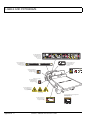
SAFETY
For any questions on material contained in this manual, contact an authorized representative for clarification.
Read and understand all labels located on the vehicle. Always replace any damaged or missing labels.
On steep hills it is possible for vehicles to coast at greater than normal speeds encountered on a flat surface. To prevent loss of vehicle control and possible serious injury, speeds should be limited to no more than the maximum speed
on level ground. See GENERAL SPECIFICATIONS. Limit speed by applying the service brake.
Catastrophic damage to the drivetrain components due to excessive speed may result from driving the vehicle above
specified speed. Damage caused by excessive speed may cause a loss of vehicle control, is costly, is considered
abuse and will not be covered under warranty.
For moving/transporting vehicle, refer to “TRANSPORTING VEHICLE”.
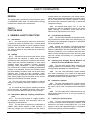
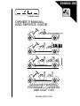
Signs similar to the ones illustrated should be used to warn of situations that could result in an unsafe condition.
BATTERY WARNING
Battery posts,
terminals and related
accessories contain
lead and lead compounds,
chemicals known
to cause cancer and
reproductive harm.
WASH HANDS
AFTER HANDLING!
BATTERIES
CONTAIN LEAD
AND RELATED PARTS
!
< 14˚ 25%
DO NOT
DRIVE ACROSS
SLOPES IN
EXCESS OF 14˚
WASH HANDS
AFTER HANDLING!
WARNING: Battery posts, terminals and related
accessories contain lead and lead compounds,
chemicals known to cause cancer and reproductive harm.
Be sure that this manual remains as part of the permanent service record should the vehicle be sold.
NOTES, CAUTIONS AND WARNINGS
Throughout this guide NOTE, CAUTION and WARNING
will be used.
A NOTE indicates a condition that should be
observed.
A CAUTION indicates a condition that
may result in damage to the vehicle.
!
!
A WARNING indicates a
hazardous condition that
could result in severe
injury or death.
Observe these NOTES, CAUTIONS and WARNINGS;
be aware that servicing a vehicle requires mechanical
skill and a regard for conditions that could be hazardous.
Improper service or repair may damage the vehicle or
render it unsafe.
The exhaust emissions of this vehicles’ engine
complies with regulations set forth by the Environmental Protection Agency (EPA) of the United States of
America (USA) at time of manufacture. Significant fines could
result from modifications or tampering with the engine, fuel,
ignition or air intake systems.
Battery posts, terminals
and related accessories
contain lead and lead
compounds. Wash hands after handling.
!
!
This spark ignition system meets all requirements of the Canadian Interference-Causing
Equipment Regulations.
Ce système d'allumage par étincelle de véhicule respecte
toutes les exigences du Règlement sur le matériel brouilleur
du Canada.
Engine exhaust from this
product contains chemicals known, in certain
quantities, to cause cancer, birth defects, or other
reproductive harm.
!
!
(NOTES, CAUTIONS AND WARNINGS CONTINUED ON INSIDE OF BACK COVER)
OWNER’S MANUAL AND
SERVICE GUIDE
GASOLINE POWERED
CARGO, PERSONNEL CARRIER
AND GOLF CAR
VEHICLES
Shuttle 2
Shuttle 4
Shuttle 6
TG5
Starting Model Year 2005
E-Z-GO Division of TEXTRON, Inc. reserves the right to make design changes without obligation to make these changes on units previously sold and the information contained in this manual is subject to change without notice.
E-Z-GO Division of TEXTRON, Inc. is not liable for errors in this manual or for incidental or consequential damages that result from the use of the material in this
manual.
TO CONTACT US
NORTH AMERICA:
TECHNICAL ASSISTANCE & WARRANTY PHONE: 1-800-774-3946, FAX: 1-800-448-8124
SERVICE PARTS PHONE: 1-888-GET-EZGO (1-888-438-3946), FAX: 1-800-752-6175
INTERNATIONAL:
PHONE: 010-1-706-798-4311, FAX: 010-1-706-771-4609
E-Z-GO DIVISION OF TEXTRON, INC., 1451 MARVIN GRIFFIN ROAD, AUGUSTA, GEORGIA USA 30906-3852
Owner’s Manual and Service Guide
Page i
NOTES
This vehicle has been designed and manufactured in the United States of America (USA) as
a ‘World Vehicle’. The Standards and Specifications listed in the following text originate in
the USA unless otherwise indicated.
The use of non Original Equipment Manufacturer (OEM) approved parts may void the
warranty.
Overfilling battery may void the warranty.
Tampering with or adjusting the governor to permit vehicle to operate at above factory
specifications will void the vehicle warranty.
When servicing engines, all adjustments and replacement components must be per original
vehicle specifications in order to maintain the United States of America Federal and State
emission certification applicable at the time of manufacture.
BATTERY PROLONGED STORAGE
All batteries will self discharge over time. The rate of self discharge varies depending on the
ambient temperature and the age and condition of the batteries.
A fully charged battery will not freeze in winter temperatures unless the temperature falls
below -75° F (-60° C).
Page ii
Owner’s Manual and Service Guide
TABLE OF CONTENTS
SAFETY ................................................................................................................... Inside covers
NOTES .........................................................................................................................................ii
SAFETY INFORMATION ............................................................................................................ v
BEFORE INITIAL USE ................................................................................................................ 1
Fig. 1 Initial Service Chart..........................................................................................................1
CONTROLS AND INDICATORS ................................................................................................ 1
KEY/LIGHT SWITCH ...........................................................................................................................................1
Fig. 2 Key/Light Switch, Low Oil Pressure Light and Fuel Gauge ............................................2
DIRECTION SELECTOR .....................................................................................................................................2
Fig. 3 Direction Selector ...........................................................................................................2
CHOKE ................................................................................................................................................................2
Fig. 4 Choke .............................................................................................................................2
FUEL GAUGE ......................................................................................................................................................2
LOW OIL PRESSURE INDICATOR LIGHT .........................................................................................................2
ACCELERATOR PEDAL .....................................................................................................................................2
Fig. 5 Accelerator and Brake Controls ......................................................................................3
HORN ..................................................................................................................................................................3
Fig. 6 Horn Button .....................................................................................................................3
OPERATING THE VEHICLE ...................................................................................................... 3
RUN-IN ................................................................................................................................................................4
Fig. 7 Check Oil Level on Dipstick ............................................................................................4
COLD STARTING ................................................................................................................................................4
STARTING AND DRIVING ..................................................................................................................................4
STARTING THE VEHICLE ON A HILL ................................................................................................................5
COASTING ..........................................................................................................................................................5
FUEL ....................................................................................................................................................................5
Fig. 8 Fueling ............................................................................................................................5
BATTERY ............................................................................................................................................................5
LABELS AND PICTOGRAMS .............................................................................................................................6
SUN TOP AND WINDSHIELD .............................................................................................................................6
VEHICLE CLEANING AND CARE ............................................................................................. 6
VEHICLE CLEANING ..........................................................................................................................................6
REPAIR ...................................................................................................................................... 6
LIFTING THE VEHICLE ......................................................................................................................................6
WHEELS AND TIRES .........................................................................................................................................7
Tire Repair ..............................................................................................................................................7
Fig. 9 Lifting the Vehicle ...........................................................................................................7
Wheel Installation ...................................................................................................................................8
LIGHT BULB REPLACEMENT ............................................................................................................................8
Fig. 10 Wheel Installation .........................................................................................................8
Fig. 11 Headlight, Turn Signal & Marker Light Bulb Replacement ...........................................9
Fig. 12 Tail and Brake Light Bulb Replacement .......................................................................9
FUSE REPLACEMENT .......................................................................................................................................8
VEHICLE WITH A DISCHARGED BATTERY .....................................................................................................8
TRANSPORTING VEHICLE .................................................................................................... 10
TOWING ............................................................................................................................................................ 10
NEUTRAL LOCK ............................................................................................................................................... 10
Fig. 13 Neutral Lock ................................................................................................................10
HAULING ........................................................................................................................................................... 10
SERVICE AND MAINTENANCE .............................................................................................. 10
SERIAL NUMBER PLATE LOCATION .............................................................................................................. 11
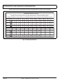
PERIODIC SERVICE SCHEDULE .................................................................................................................... 12
Fig. 14 Periodic Service Schedule .......................................................................................... 12
TIRE INSPECTION ............................................................................................................................................ 14
CHECKING THE OIL LEVEL ............................................................................................................................. 14
Fig. 15 Clean Entire Dipstick .................................................................................................. 14
Owner’s Manual and Service Guide
Page iii
TABLE OF CONTENTS
Fig. 16 Check Oil Level on Dipstick ....................................................................................... 14
CHANGING THE OIL ........................................................................................................................................ 14
Fig. 17 Oil Viscosity Chart ...................................................................................................... 15
Fig. 18 Clean Top of Engine .................................................................................................. 15
Fig. 19 Remove Oil Filter ....................................................................................................... 15
Fig. 20 Clean Oil Filter ........................................................................................................... 15
Fig. 21 Blowing Out Oil Filter ................................................................................................. 16
Fig. 22 Add Engine Oil ........................................................................................................... 16
STARTER/GENERATOR BELT TENSION ....................................................................................................... 16
Fig. 23 Checking Belt Tension with Gauge ............................................................................ 16
Adjusting the Belt ................................................................................................................................. 17
Fig. 24 Checking Belt Tension Manually ................................................................................ 17
Fig. 25 Adjusting Belt Tension ............................................................................................... 17
BATTERY CLEANING ...................................................................................................................................... 17
BRAKES ........................................................................................................................................................... 17
Periodic Brake Test for Mechanical Brakes ......................................................................................... 18
Fig. 26 Preparing Acid Neutralizing Solution .......................................................................... 18
Fig. 27 Typical Brake Performance Test ................................................................................ 18
HYDRAULIC FRONT DISC BRAKES (If Equipped) .......................................................................................... 19
AIR INTAKE AND COOLING FINS.................................................................................................................... 19
Fig. 28 Cleaning Air Intake...................................................................................................... 19
Fig. 29 Cleaning the Cooling Fins ........................................................................................... 19
REAR AXLE ....................................................................................................................................................... 20
Fig. 30 Add, Check and Drain Rear Axle Lubricant ................................................................ 20
Checking the Lubricant Level................................................................................................................ 20
AIR CLEANER INSPECTION AND REPLACEMENT........................................................................................ 20
Fig. 31 Air Cleaner .................................................................................................................. 20
Cleaning the Air Filter Element ............................................................................................................. 20
LUBRICATION................................................................................................................................................... 20
SPARK PLUGS.................................................................................................................................................. 21
DIRECTION SELECTOR (Dual Cable system) ................................................................................................. 21
Fig. 32 Lubrication Points........................................................................................................ 21
Fig. 33 Shift Cable Adjustment................................................................................................ 21
PROLONGED STORAGE ................................................................................................................................. 21
HARDWARE ...................................................................................................................................................... 22
Fig. 34 Torque Specifications.................................................................................................. 22
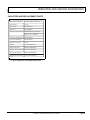
CAPACITIES AND REPLACEMENT PARTS .................................................................................................... 23
Fig. 35 Capacities and Replacement Parts............................................................................. 23
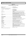
GENERAL SPECIFICATIONS................................................................................................... 25
SHUTTLE 2 GASOLINE POWERED CARGO CARRIER ................................................................................. 26
SHUTTLE 4 GASOLINE POWERED PERSONNEL / CARGO CARRIER ........................................................ 27
SHUTTLE 6 GASOLINE POWERED PERSONNEL CARRIER ........................................................................ 28
TG5 GASOLINE POWERED 5 PASSENGER GOLF CAR ............................................................................... 29
Fig. 36 Vehicle Dimensions..................................................................................................... 30
Fig 37 Vehicle Dimensions....................................................................................................... 31
Fig 38 Vehicle Dimensions and Incline Specifications ............................................................. 32
VEHICLE WARRANTIES .......................................................................................................... 35
DOMESTIC WARRANTY .................................................................................................................................. 36
INTERNATIONAL WARRANTY......................................................................................................................... 37
FEDERAL EMISSION COMPONENT DEFECT WARRANTY........................................................................... 39
CALIFORNIA EMISSION CONTROL WARRANTY STATEMENT .................................................................... 41
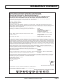
DECLARATION OF CONFORMITY .......................................................................................... 45
LABELS AND PICTOGRAMS .................................................................................... Appendix A
Page iv
Owner’s Manual and Service Guide
SAFETY INFORMATION
This manual has been designed to assist in maintaining the vehicle in accordance with procedures developed by the
manufacturer. Adherence to these procedures and troubleshooting tips will ensure the best possible service from the
product. To reduce the chance of personal injury or property damage, the following must be carefully observed:
Certain replacement parts can be used independently and/or in combination with other accessories to modify an E-ZGO-manufactured vehicle to permit the vehicle to operate at or in excess of 20mph. When an E-Z-GO-manufactured
vehicle is modified an any way by the Distributor, Dealer or customer to operate at or in excess of 20mph, UNDER
FERERAL LAW the modified product will be a Low Speed Vehicle (LSV) subject to the strictures and requirements of
Federal Motor Vehicle Safety Standard 571.500. In these instances, pursuant to Federal law the Distributor or Dealer
MUST equip the product with headlights, rear lights, turn signals, seat belts, top, horn and all other modifications for
LSV’s mandated in FMVSS 571.500, and affix a Vehicle Identification Number to the product in accordance with the
requirements of FMVSS 571.565. Pursuant to FMVSS 571.500, and in accordance with the State laws applicable in the
places of sale and use of the product, the Distributor, Dealer or customer modifying the vehicle also will be the Final
Vehicle Manufacturer for the LSV, and required to title or register the vehicle as mandated by State law.
E-Z-GO will NOT approve Distributor, Dealer or customer modifications converting E-Z-GO products into LSV’s.
The Company, in addition, recommends that all E-Z-GO products sold as personal transportation vehicles BE OPERATED ONLY BY PERSONS WITH VALID DRIVERS LICENSES, AND IN ACCORDANCE WITH APPLICABLE STATE
REQUIREMENTS. This restriction is important to the SAFE USE AND OPERATION of the product. On behalf of E-ZGO, I am directing that E-Z-GO Branch personnel, Distributors and Dealers advise all customers to adhere to this
SAFETY RESTRICTION, in connection with the use of all products, new and used, the Distributor or Dealer has reason to believe may be operated in personal transportation applications.
Information on FMVSS 571.500 can be obtained at Title 49 of the Code of Federal Regulations, section 571.500, or
through the Internet at the website for the U.S. Department of Transportation - at Dockets and Regulation, then to Title
49 of the Code of Federal Regulations (Transportation).
GENERAL
Many vehicles are used for a variety of tasks beyond the original intended use of the vehicle; therefore, it is impossible
to anticipate and warn against every possible combination of circumstances that may occur. No warnings can take the
place of good common sense and prudent driving practices.
Good common sense and prudent driving practices do more to prevent accidents and injury than all of the warnings
and instructions combined. The manufacturer strongly suggests that all users and maintenance personnel read this
entire manual paying particular attention to the CAUTIONS and WARNINGS contained therein.
If you have any questions regarding this vehicle, contact your closest representative or write to the address on the back
cover of this publication, Attention: Product Service Department.
The manufacturer reserves the right to make design changes without obligation to make these changes on units previously sold and the information contained in this manual is subject to change without notice.
The manufacturer is not liable for errors in this manual or for incidental or consequential damages that result from the
use of the material in this manual.
This vehicle conforms to the current applicable standard(s) for safety and performance requirements.
These vehicles are designed and manufactured for off-road use. They do not conform to Federal Motor Vehicle Safety
Owner’s Manual and Service Guide
Page v
SAFETY INFORMATION
Standards of the United States of America (USA) and are not equipped for operation on public streets. Some communities may permit these vehicles to be operated on their streets on a limited basis and in accordance with local ordinances.
Refer to GENERAL SPECIFICATIONS for vehicle seating capacity.
Never modify the vehicle in any way that will alter the weight distribution of the vehicle, decrease its stability
or increase the speed beyond the factory specification. Such modifications can cause serious personal injury
or death. Modifications that increase the speed and/or weight of the vehicle will extend the stopping distance and may
reduce the stability of the vehicle. Do not make any such modifications or changes. The manufacturer prohibits and
disclaims responsibility for any such modifications or any other alteration which would adversely affect the safety of the
vehicle.
Vehicles that are capable of higher speeds must limit their speed to no more than the speed of other vehicles when
used in a golf course environment. Additionally, speed should be further moderated by the environmental conditions,
terrain and common sense.
GENERAL OPERATION
Always:
• Use the vehicle in a responsible manner and maintain the vehicle in safe operating condition.
• Read and observe all warnings and operation instruction labels affixed to the vehicle.
• Follow all safety rules established in the area where the vehicle is being operated.
• Reduce speed to compensate for poor terrain or conditions.
• Apply service brake to control speed on steep grades.
• Maintain adequate distance between vehicles.
• Reduce speed in wet areas.
• Use extreme caution when approaching sharp or blind turns.
• Use extreme caution when driving over loose terrain.
• Use extreme caution in areas where pedestrians are present.
MAINTENANCE
Always:
• Maintain the vehicle in accordance with the manufacturer’s periodic service schedule.
• Ensure that repairs are performed by those that are trained and qualified to do so.
• Follow the manufacturer’s maintenance procedures for the vehicle. Be sure to disable the vehicle before performing
any maintenance. Disabling includes removing the key from the key switch and removal of a battery wire.
• Insulate any tools used within the battery area in order to prevent sparks or battery explosion caused by shorting the
battery terminals or associated wiring. Remove the battery or cover exposed terminals with an insulating material.
• Use specified replacement parts. Never use replacement parts of lesser quality.
Page vi
Owner’s Manual and Service Guide
SAFETY INFORMATION
• Use recommended tools.
• Determine that tools and procedures not specifically recommended by the manufacturer will not compromise the
safety of personnel nor jeopardize the safe operation of the vehicle.
• Support the vehicle using wheel chocks and jack stands. Never get under a vehicle that is supported by a jack. Lift
the vehicle in accordance with the manufacturer’s instructions.
• Empty the fuel tank or plug fuel hoses to prevent fuel leakage.
• Maintain the vehicle in an area away from exposed flame or persons who are smoking.
• Be aware that a vehicle that is not performing as designed is a potential hazard and must not be operated.
• Test drive the vehicle after any repairs or maintenance. All tests must be conducted in a safe area that is free of both
vehicular and pedestrian traffic.
• Replace damaged or missing warning, caution or information labels.
• Keep complete records of the maintenance history of the vehicle.
The manufacturer cannot anticipate all situations, therefore people attempting to maintain or repair the vehicle must
have the skill and experience to recognize and protect themselves from potential situations that could result in severe
personal injury or death and damage to the vehicle. Use extreme caution and, if unsure as to the potential for injury,
refer the repair or maintenance to a qualified mechanic.
VENTILATION
Always store gasoline vehicles in a well ventilated area. Ventilation prevents gasoline fumes from accumulating.
Never fuel a vehicle in an area that is subject to flame or spark. Pay particular attention to natural gas or propane water
heaters and furnaces.
Never work around or operate a vehicle in an environment that does not ventilate exhaust gases from the area. Carbon
monoxide is a dangerous gas that can cause unconsciousness and is potentially lethal.
Owner’s Manual and Service Guide
Page vii
SAFETY INFORMATION
Notes:
Page viii
Owner’s Manual and Service Guide
SAFETY INFORMATION
Read all of manual to become thoroughly familiar with this vehicle. Pay particular attention to all Notes, Cautions and Warnings
GENERAL
The following text is provided as recommended by part II
of ASME/ANSI B56.8-1988. The Manufacturer strongly
endorses the contents of this specification.
manual without the manufacturer’s prior written authorization. Where authorized modifications have been made,
the user shall ensure that capacity, operation, warning,
and maintenance instruction plates, tags, or decals are
changed accordingly.
PART II
FOR THE USER
4.3.3 As required under paras. 4.3.1 or 4.3.2, the
manufacturer shall be contacted to secure new nameplates, warnings, or instructions which shall then be
affixed in their proper place on the carrier.
4 GENERAL SAFETY PRACTICES
4.4
4.1
Introduction
4.1.1 Like other machines, carriers can cause injury
if improperly used or maintained. Part II contains broad
safety practices applicable to carrier operations. Before
operation, the user shall establish such additional specific safety practices as may reasonably be required for
safe operation.
4.2
Stability
4.2.1
Experience has shown that this vehicle, which
complies with this standard, is stable when properly
operated and when operated in accordance with specific
safety rules and practices established to meet actual
operating terrain and conditions. However, improper
operation, faulty maintenance, or poor housekeeping
may contribute to a condition of instability and defeat the
purpose of the standard. Some of the conditions which
may affect stability are failure of the user to follow safety
practices; also, ground and floor conditions, grade,
speed, loading, the operation of the carrier with improper
loads, battery weight, dynamic and static forces, and the
judgement exercised by the carrier operator.
(a) The user shall train carrier operators to adhere
strictly to the operating instructions stated in this Standard.
(b) The user shall survey specific operating conditions
and environment, and establish and train carrier operators to comply with additional, specific safety practices.
4.3
Nameplates, Markings, Capacity, and Modifications
4.3.1 The user shall maintain in a legible condition
all nameplates, warnings, and instructions which are
supplied by the manufacturer.
4.3.2 The user shall not perform any modification or
addition which affects capacity or safe operation, or
make any change not in accordance with the owner’s
Fuel Handling and Storage
4.4.1 The user shall supervise the storage and handling of liquid fuels (when used) to be certain that it is in
accordance with appropriate paragraphs of ANSI/NFPA
505 and ANSI/NFPA 30.
4.4.2 Storage and handling of liquefied petroleum
gas fuels shall be in accordance with appropriate paragraphs of ANSI/NFPA 505 and ANSI/NFPA 58. If such
storage or handling is not in compliance with these standards, the user shall prevent the carrier from being used
until such storage and handling is in compliance with
these standards.
4.5
Changing and Charging Storage Batteries for
Electric Personnel and Burden Carriers
4.5.1 The user shall require battery changing and
charging facilities and procedures to be in accordance
with appropriate paragraphs of ANSI/NFPA 505.
4.5.2 The user shall periodically inspect facilities
and review procedures to be certain that appropriate
paragraphs of ANSI/NFPA 505, are strictly complied with,
and shall familiarize carrier operators with it.
4.6
Hazardous Locations
4.6.1 The user shall determine the hazard classification of the particular atmosphere or location in which
the carrier is to be used in accordance with ANSI/NFPA
505.
4.6.2 The user shall permit in hazardous areas only
those carriers approved and of the type required by
ANSI/NFPA 505.
4.7
Lighting for Operating Areas
4.7.1 The user, in accordance with his responsibility
to survey the environment and operating conditions, shall
determine if the carrier requires lights and, if so, shall
equip the carrier with appropriate lights in accordance
with the manufacturer’s recommendations.
Owner’s Manual and Service Guide
Page ix
SAFETY INFORMATION
Read all of manual to become thoroughly familiar with this vehicle. Pay particular attention to all Notes, Cautions and Warnings
4.8
Control of Noxious Gases and Fumes
turer;
4.8.1 When equipment powered by internal combustion engines is used in enclosed areas, the atmosphere shall be maintained within limits specified in the
American Conference of Governmental Industrial
Hygienists publication, “Threshold Limit Values for
Chemical Substances and Physical Agents in the Workroom Environment”. This shall be accomplished by ventilation provided by the user, and/or the installation, use,
and proper maintenance of emission control equipment
recommended or provided by the manufacturer of the
equipment.
(b) emphasis on safety of passengers, material loads,
carrier operator, and other employees;
4.9
(e) operational performance tests and evaluations during, and at completion of, the program.
Warning Device(s)
4.9.1 The user shall make periodic inspections of
the carrier to be certain that the sound-producing and/or
visual device(s) are maintained in good operating condition.
(c) general safety rules contained within this Standard
and the additional specific rules determined by the user
in accordance with this Standard, and why they were formulated;
(d) introduction of equipment, control locations and
functions, and explanation of how they work when used
properly and when used improperly, and surface conditions, grade, and other conditions of the environment in
which the carrier is to be operated;
5.3
Personnel and Burden Carrier Operator
Responsibility
4.9.2 The user shall determine if operating conditions require the carrier to be equipped with additional
sound-producing and/or visual devices and be responsible for providing and maintaining such devices, in accordance with the manufacturer’s recommendations.
5.3.1 Operators shall abide by the following safety
rules and practices in paras. 5.4, 5.5, 5.6, and 5.7.
5 OPERATING SAFETY RULES AND
PRACTICES
5.4.2 Riding on the carrier by persons other than the
operator is authorized only on personnel seat(s) provided
by the manufacturer. All parts of the body shall remain
within the plan view outline of the carrier.
5.1
Personnel and Burden Carrier Operator
Qualifications
5.1.1 Only persons who are trained in the proper
operation of the carrier shall be authorized to operate the
carrier. Operators shall be qualified as to visual, auditory,
physical, and mental ability to safely operate the equipment according to Section 5 and all other applicable
parts of this Standard.
5.2
Personnel and Burden Carrier Operators’
Training
5.2.1 The user shall conduct an operators’ training
program.
5.2.2 Successful completion of the operators’ training program shall be required by the user before operation of the carrier. The program shall be presented in its
entirety to all new operators and not condensed for those
claiming previous experience.
5.2.3 The user should include in the operators’ training program the following:
(a)
Page x
instructional material provided by the manufac-
5.4
General
5.4.1 Safeguard the pedestrians at all times. Do not
drive carrier in a manner that would endanger anyone.
5.4.3 When a carrier is to be left unattended, stop
carrier, apply the parking brake, stop the engine or turn
off power, turn off the control or ignition circuit, and
remove the key if provided. Block the wheels if machine
is on an incline.
5.4.4 A carrier is considered unattended when the
operator is 25 ft. (7.6 m) or more from the carrier which
remains in his view, or whenever the operator leaves the
carrier and it is not within his view. When the operator is
dismounted and within 25 ft. (7.6 m) of the carrier still in
his view, he still must have controls neutralized, and the
parking brake(s) set to prevent movement.
5.4.5 Maintain a safe distance from the edge of
ramps and platforms.
5.4.6 Use only approved carriers in hazardous locations, as defined in the appropriate safety standards.
5.4.7 Report all accidents involving personnel,
building structures, and equipment.
5.4.8
rier.
Operators shall not add to, or modify, the car-
Owner’s Manual and Service Guide
SAFETY INFORMATION
Read all of manual to become thoroughly familiar with this vehicle. Pay particular attention to all Notes, Cautions and Warnings
5.4.9 Carriers shall not be parked or left unattended
such that they block or obstruct fire aisles, access to
stairways, or fire equipment.
5.5
Traveling
5.5.1 Observe all traffic regulations, including authorized speed limits. Under normal traffic conditions keep
to the right. Maintain a safe distance, based on speed of
travel, from a carrier or vehicle ahead; and keep the carrier under control at all times.
5.5.2 Yield the right of way to pedestrians, ambulances, fire trucks, or other carriers or vehicles in emergency situations.
5.5.3 Do not pass another carrier or vehicle traveling in the same direction at intersections, blind spots, or
at other dangerous locations.
5.5.4 Keep a clear view of the path of travel,
observe other traffic and personnel, and maintain a safe
clearance.
5.5.5 Slow down or stop, as conditions dictate, and
activate the sound-producing warning device at cross
aisles and when visibility is obstructed at other locations.
5.5.6
Ascend or descend grades slowly.
5.5.7 Avoid turning, if possible, and use extreme
caution on grades, ramps, or inclines; normally travel
straight up and down.
5.5.8 Under all travel conditions the carrier shall be
operated at a speed that will permit it to be brought to a
stop in a safe manner.
smooth, sweeping motion.
5.6
Loading
5.6.1 Handle only stable and safely arranged loads.
When handling off-center loads which cannot be centered, operate with extra caution.
5.6.2 Handle only loads within the capacity of the
carrier as specified on the nameplate.
5.6.3 Handle loads exceeding the dimensions used
to establish carrier capacity with extra caution. Stability
and maneuverability may be adversely affected.
5.7
Operator Care of Personnel and Burden
Carriers
5.7.1 At the beginning of each shift during which the
carrier will be used, the operator shall check the carrier
condition and inspect the tires, warning devices, lights,
battery(s), speed and directional controllers, brakes, and
steering mechanism. If the carrier is found to be in need
of repair, or in any way unsafe, the matter shall be
reported immediately to the designated authority and the
carrier shall not be operated until it has been restored to
safe operating condition.
5.7.2 If during operation the carrier becomes unsafe
in any way, the matter shall be reported immediately to
the designated authority, and the carrier shall not be
operated until it has been restored to safe operating condition.
5.7.3 Do not make repairs or adjustments unless
specifically authorized to do so.
5.5.9 Make starts, stops, turns, or direction reversals in a smooth manner so as not to shift the load,
endanger passengers, or overturn the carrier.
5.7.4 The engine shall be stopped and the operator
shall leave the carrier while refueling.
5.5.10 Do not indulge in dangerous activities, such as
stunt driving or horseplay.
5.7.5 Spillage of oil or fuel shall be carefully and
completely absorbed or evaporated and fuel tank cap
replaced before starting engine.
5.5.11 Slow down when approaching, or on, wet or
slippery surfaces.
5.5.12 Do not drive carrier onto any elevator unless
specifically authorized to do so. Approach elevators
slowly, and then enter squarely after the elevator car is
properly leveled. Once on the elevator, neutralize the
controls, shut off power, and set parking brakes. It is
advisable that all other personnel leave the elevator
before a carrier is allowed to enter or exit.
5.5.13 Avoid running over loose objects, potholes,
and bumps.
5.5.14 To negotiate turns, reduce speed to improve
stability, then turn hand steering wheel or tiller in a
5.7.6 Do not operate a carrier with a leak in the fuel
system or battery(s).
5.7.7 Do not use open flames for checking electrolyte level in storage battery(s) or liquid level in fuel tanks.
6 MAINTENANCE PRACTICES
6.1
Introduction
6.1.1 Carriers may become hazardous if maintenance is neglected. Therefore, maintenance facilities,
trained personnel, and procedures shall be provided.
Such facilities may be on or off the premises.
Owner’s Manual and Service Guide
Page xi
SAFETY INFORMATION
Read all of manual to become thoroughly familiar with this vehicle. Pay particular attention to all Notes, Cautions and Warnings
6.2
Maintenance Procedures
6.2.1 Maintenance and inspection of all carriers
shall be performed in conformance with the manufacturer’s recommendations and the following practices.
(a) A scheduled preventive maintenance, lubrication,
and inspection system shall be followed.
(b) Only qualified and authorized personnel shall be
permitted to maintain, repair, adjust, and inspect carriers.
(c) Before undertaking maintenance or repair, follow
the manufacturer’s recommendations for immobilizing
the carrier.
(d) Block chassis before working underneath it.
(e) Before disconnecting any part of the engine fuel
system of a gasoline or diesel powered carrier with gravity feed fuel systems, be sure shutoff valve is closed, and
run engine until fuel system is depleted and engine stops
running.
(f) Before disconnecting any part of the engine fuel
system of LP gas powered carriers, close the LP gas cylinder valve and run the engine until fuel in the system is
depleted and the engine stops running.
(g) Operation to check performance of the carrier shall
be conducted in an authorized area where safe clearance exists.
(h) Before commencing operation of the carrier, follow
the manufacturer’s instructions and recommended procedures.
(i) Avoid fire hazards and have fire protection equipment present in the work area. Do not use an open flame
to check level or leakage of fuel, battery electrolyte, or
coolant. Do not use open pans of fuel or flammable
cleaning fluids for cleaning parts.
prevent the use of the carrier until the leak has been
eliminated.
(o) The carrier manufacturer’s capacity, operation, and
maintenance instruction plates, tags, or decals shall be
maintained in legible condition.
(p) Batteries, motors, speed and directional controllers, limit switches, protective devices, electrical conductors, and connections shall be inspected and maintained
in conformance with manufacturers recommended procedures.
(q) Carriers shall be kept in a clean condition to minimize fire hazards and facilitate detection of loose or
defective parts.
(r) Modifications and additions which affect capacity
and safe machine operation shall not be performed by
the customer or user without manufacturer’s prior written
authorization; where authorized modifications have been
made, the user shall ensure that capacity, operation,
warning, and maintenance instruction plates, tags, or
decals are changed accordingly.
(s) Care shall be taken to ensure that all replacement
parts are interchangeable with the original parts and of a
quality at least equal to that provided in the original
equipment.
END OF ASME/ANSI B56.8 - 1988 TEXT
(j) Properly ventilate the work area.
(k) Handle LP gas cylinders with care. Physical damage, such as dents, scrapes, or gouges, may dangerously weaken the tank and make it unsafe for use.
(l) Brakes, steering mechanisms, speed and directional control mechanisms, warning devices, lights, governors, guards, and safety devices shall be inspected
regularly and maintained in a safe operating condition.
(m)
Special carriers or devices designed and
approved for hazardous area operation shall be
inspected to ensure that maintenance preserves the original approved safe operating features.
(n) Fuel systems shall be checked for leaks and condition of parts. If a leak is found, action shall be taken to
Page xii
Owner’s Manual and Service Guide
SAFETY INFORMATION
Read all of manual to become thoroughly familiar with this vehicle. Pay particular attention to all Notes, Cautions and Warnings
GENERAL
5.2.1. Steep Grade
The following text is provided as recommended by part II
of ANSI / GCMA Z130.1 - 1993. E-Z-GO, as a member of
the National Golf Car Manufacturers Association
(NGCMA), strongly endorses the contents of this specification.
In areas where steep grades exist, golf car operations
should be restricted to the designated golf car pathways
where possible, and shall be identified with a suitable
warning giving the following information: “Warning, steep
grade, descend slowly with one foot on brake.”
PART II
5.2.2. Wet Areas
MAINTENANCE AND OPERATIONS
5.
GENERAL SAFETY PRACTICES
5.1.
Introduction
Like other machines, golf cars can cause injury if improperly used or maintained. This section contains broad
safety practices recommended for safe golf car operations. Before operation, the controlling party should
establish such additional specific safety practices as may
be reasonably required for safe operations.
Experience has shown that golf cars which comply with
the provisions stated in Part II of this Standard are safe
when properly operated in accordance with the safety
and operation warnings affixed to every golf car. The safe
operation is enhanced when the golf cars are operated
within a specific set of operation instructions, safety rules
and practices established to meet actual operating terrain and conditions.
The safety information contained in Part II is intended to
provide the controlling party with basic safety information
and to encourage the controlling party to implement a
golf car safety program.
It is suggested and recommended that Part II be
reprinted in the golf car manufacturer’s operation and
service manuals to encourage safe operations and practices at the controlling party’s facility.
5.2.
Safety Survey
The controlling party shall perform a safety survey periodically, and as conditions warrant to their premises, to
identify areas where golf cars should not be operated
and to identify possible hazards.
Wet grassy areas may cause a golf car to lose traction
and may affect stability. Wet areas shall be chained or
roped off to prevent golf car operations or be identified by
a suitable warning not to operate golf cars in this area
due to wet terrain.
5.2.3. Sharp
Approaches
Turns,
Blind
Corners,
Bridge
Sharp turns, blind spots, bridge approaches and other
potentially hazardous areas shall be either chained or
roped off to prevent golf car operations or identified with
a suitable warning to the operator of the nature of the
hazard and stating the proper precautions to be taken to
avoid the hazard.
5.2.4. Loose Terrain
Loose terrain may cause a golf car to lose traction and
may affect stability. Areas of loose terrain should be
repaired if possible, or chained or roped off to prevent
golf car operation or identified by a suitable warning to
operators not to operate golf cars in this area due to
loose terrain or possible hazardous conditions.
5.2.5. Golf Car/Pedestrian Interference Areas
Areas where pedestrians and golf cars interfere shall be
avoided whenever possible by rerouting the golf car traffic or the pedestrian traffic to eliminate the interference. If
elimination of the interference is not possible or is highly
impractical, signs shall be erected warning pedestrians
of the golf car traffic and golf car operators of the pedestrian traffic and to drive slowly and use extreme caution.
Owner’s Manual and Service Guide
Page xiii
SAFETY INFORMATION
Read all of manual to become thoroughly familiar with this vehicle. Pay particular attention to all Notes, Cautions and Warnings
6.
MAINTENANCE
6.1. Introduction
6.1.1. Golf cars may become hazardous if maintenance
is neglected or improperly performed. Therefore maintenance facilities, trained personnel and procedures in
accordance with the manufacturer’s recommendations
should be provided by the controlling party.
6.2. Preventive Maintenance
A regularly scheduled inspection and preventive maintenance program in accordance with the manufacturer’s
recommendations should be established. Such a program will be a valuable tool in providing the golfing
patron with a safe, properly operating golf car and
thereby help to avoid accidents.
6.2.1. Personnel
Only qualified, trained and authorized personnel shall be
permitted to inspect, adjust and maintain golf cars.
6.2.4. Maintenance Procedures
All maintenance shall be performed in accordance with
the manufacturer’s recommended maintenance procedures as outlined in the manufacturer’s operation and
service manuals.
6.2.5. Maintenance Safety Procedures
All maintenance shall be performed in accordance with
the manufacturer’s recommended safety procedures as
outlined in the manufacturer’s operation and service
manuals. The following list of recommended safety procedures are general in nature and in no way supersede
the manufacturer’s specific instructions.
6.2.5.1. Follow manufacturer’s instructions for immobilizing golf car before beginning any maintenance.
6.2.2. Parts and Materials
Only manufacturer’s recommended replacement parts
and materials shall be used.
6.2.3. Ventilation
Maintenance and storage areas shall be properly ventilated to avoid fire hazards in accordance with applicable
fire codes and ordinances.
6.2.3.1. Ventilation for gasoline powered golf cars shall
be provided to remove flammable vapors, fumes and
other flammable materials. Consult applicable fire codes
for specific levels of ventilation.
6.2.3.2. Ventilation for electric powered golf cars shall
be provided to remove the accumulation of flammable
hydrogen gas emitted during the charging process. The
amount of hydrogen gas emitted depends upon a number of factors such as the condition of the batteries, the
output rate of the battery charger and the amount of time
the batteries are on charge. Hydrogen emissions are
generally considered to be in the area of 10 to 20 cubic
Page xiv
liters per car per charge. Because of the highly volatile
nature of hydrogen gas and its propensity to rise and
accumulate at the ceiling in pockets, a minimum of 5 air
changes per hour is recommended. The controlling party
shall consult applicable fire and safety codes for the specific ventilation levels required as well as the use of
explosion proof electrical apparatus.
6.2.5.2. Block chassis before working underneath golf
car.
6.2.5.3. Before disconnecting any part of the fuel system, drain the system and turn all shut off valves to the
‘OFF’ position to prevent leakage or accumulation of
flammable fuels in the work area.
6.2.5.4. Avoid fire hazards and have fire protection
equipment available.
6.2.5.5. Before performing any maintenance on an electric golf car, disable the electrical system in accordance
with the manufacturer’s instructions.
6.2.5.6. Use only properly insulated tools when working
on electrically powered golf cars or around batteries.
6.2.5.7. Brakes, steering mechanisms, warning devices,
Owner’s Manual and Service Guide
SAFETY INFORMATION
Read all of manual to become thoroughly familiar with this vehicle. Pay particular attention to all Notes, Cautions and Warnings
governors and all other safety devices shall be inspected
and maintained in a safe and proper operating condition
and shall not be modified as supplied by the manufacturer.
6.2.5.8. After each maintenance or repair the golf car
shall be driven by qualified, trained and authorized personnel to ensure proper operation and adjustment.
6.2.5.9. Driving golf car to check for proper operation
and adjustment after repair shall be performed in an area
that is free of vehicular and pedestrian traffic.
6.2.5.10. Record all maintenance performed in a maintenance record log by date, name of person performing
maintenance and type of maintenance. Controlling party
management should periodically inspect maintenance
log to ensure currency and completeness of entries.
6.2.5.11. Provide operator comment cards to assist in
identifying non-periodic maintenance needs for specific
golf cars.
6.2.6. The controlling party shall maintain in a legible
condition all nameplates, warnings and instructions
which are supplied by the manufacturer.
6.2.7. The controlling party shall not perform any modification or addition which affects capacity or safe operation, or make any change not in accordance with the
owner’s manual without the manufacturer’s prior written
authorization. Where authorized modifications have been
made, the controlling party shall ensure that capacity,
operation, warning and maintenance instruction plates,
tags or decals are changed accordingly.
6.2.8. As required under paragraphs 6.2.6 and 6.2.7 the
manufacturer shall be contacted to secure new nameplates, warnings or instructions which shall then be
affixed in their proper place on the golf car.
7. FUELS HANDLING AND STORAGE/
BATTERY CHARGING
7.1.
The controlling party shall supervise the storage
and handling of liquid fuels in accordance with applicable
fire and safety requirements.
7.2.
Storage and handling of liquefied petroleum gas
fuels shall be in accordance with American Gas Association recommendations and applicable fire safety requirements.
7.3.
The controlling party shall require battery changing and charging facilities and procedures to be in accordance with applicable ordinances or regulations (also
see paragraph 6.2.3.2).
7.4.
The controlling party shall periodically inspect
facilities and review procedures to be certain that the
procedures in paragraphs 6.2.3.2 and 7.3 are being followed.
8. OPERATING SAFETY RULES AND
PRACTICES
8.1. Operator Qualifications
8.1.1. Only authorized persons shall be allowed to operate golf cars. It is recommended that no persons be
allowed to operate golf cars except those persons who
posses a valid motor vehicle driver’s license.
8.1.2. The controlling party shall display the operation
and safety instructions as recommended by the golf car
manufacturers and the golf course safety rules in a conspicuous place near the golf car rental area or golf car
pick-up area. It is also recommended, as with all motor
vehicles, that the warning “Do not operate golf cars when
under the influence of alcohol or drugs.” be posted in a
conspicuous location.
Owner’s Manual and Service Guide
Page xv
SAFETY INFORMATION
Read all of manual to become thoroughly familiar with this vehicle. Pay particular attention to all Notes, Cautions and Warnings
Notes:
Page xvi
Owner’s Manual and Service Guide
OPERATION AND SERVICE INFORMATION
Read all of manual to become thoroughly familiar with this vehicle. Pay particular attention to all Notes, Cautions and Warnings
Thank you for purchasing this vehicle. Before driving the
vehicle, we ask you to spend some time reading this
Owner’s Manual and Service Guide. This guide contains
the information that will assist you in maintaining this
highly reliable vehicle. Some illustrations may show
items that are optional for your vehicle. This guide covers
the operation of several vehicles; therefore, some pictorial views may not represent your vehicle. Physical differences in controls will be illustrated.
This vehicle has been designed and manufactured as a
‘World Vehicle’. Some countries have individual requirements to comply with their specifications; therefore,
some sections may not apply in your country.
Most of the service procedures in this guide can be
accomplished using common automotive hand tools.
Contact your service representative on servicing the
vehicle in accordance with the Periodic Service Schedule.
Service Parts Manuals and Technician’s Repair and Service Manuals are available from a local Distributor, an
authorized Branch or the Service Parts Department.
When ordering parts or requesting information for your
vehicle, provide vehicle model, serial number and manufacture code.
BEFORE INITIAL USE
Read, understand and follow the safety label on the
instrument panel. Be sure you understand how to operate the vehicle, its equipment and how to use it safely.
Maintaining good performance depends to a large extent
on the operator.
Hydrogen gas is generated as a natural part of the
lead acid battery charging process. A 4% concentration of hydrogen gas is
explosive and could cause severe injury or death.
Charging must take place in an area that is adequately ventilated (minimum of 5 air exchanges per hour).
!
!
To reduce the chance of battery explosion that could
result in severe injury or death, never smoke around
or charge batteries in an area that has open flame or
electrical equipment that could cause an electrical
arc.
Before a new vehicle is put into operation, the items
shown in the INITIAL SERVICE CHART must be performed (Ref. Fig. 1 on page 1) .
Vehicle battery must be fully charged before initial use.
Check for correct tire inflation. See GENERAL SPECIFICATIONS.
Check for oil or fuel leaks that could have developed in
shipment from the factory.
Determine and record braking distance required to stop
vehicle for future brake performance tests.
Remove the protective clear plastic, that protect the seat
bottom and back rest during shipping, before placing the
vehicle in service.
ARTICLE
Batteries
OPERATION D’ENTRETIEN
Charger les batteries
Sièges
Retirer les revêtements en plastique
Freins
Vérifier le fonctionnement et régler au besoin
Vérifier le niveau d'huile hydraulique, s'il y a lieu
Définir la distance d'arrêt admissible
Pneus
Vérifier la pression d'air (voir SPECIFICATIONS)
Carburant
Remplir le réservoir de carburant recommandé
Moteur
Vérifier le niveau d'huile
Ref Isc 6
Fig. 1 Initial Service Chart
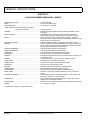
CONTROLS AND INDICATORS
Vehicle controls and indicators consist of:
• key/light switch
• direction selector
• choke
• fuel gauge
• low oil pressure indicator light
• accelerator pedal
• combination service and
park brake pedal
• horn
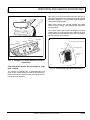
KEY/LIGHT SWITCH
Located on the dash panel, this switch enables the basic
electrical system of the vehicle to be turned on and off by
turning the key. To prevent inadvertent operation of the
vehicle when left unattended, the key should be turned to
the ‘OFF’ position and removed (Ref. Fig. 2 on page 2).
If the vehicle is equipped with lights, the key switch has a
position to operate them, indicated by the light icon.
Owner’s Manual and Service Guide
Page 1
OPERATION AND SERVICE INFORMATION
Read all of manual to become thoroughly familiar with this vehicle. Pay particular attention to all Notes, Cautions and Warnings
Commutateur à clé/
interrupteur des feux
Jauge de
carburant
E
F
FUE
L
Voyant lumineux de
basse pression d'huile
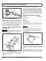
Fig. 2 Key/Light Switch, Low Oil Pressure Light and
Fuel Gauge
If the vehicle is equipped with factory installed
custom accessories, some accessories remain
operational with the key switch in the ‘OFF’ position.
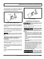
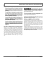
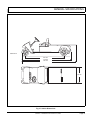
Starter
Fig. 4 Choke
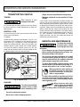
DIRECTION SELECTOR
To reduce the possibility of component
damage, the vehicle must be completely stopped before moving the direction selector.
Located on the seat support panel, this lever permits the
selection of either ‘F’ (forward) or ‘R’ (reverse) (Ref. Fig.
3 on page 2). Vehicle should be left in ‘F’ when unattended.
Neutral
Reverse
FUEL GAUGE
The electric fuel gauge is located on the dash panel (Ref.
Fig. 2 on page 2).
LOW OIL PRESSURE INDICATOR LIGHT
A low oil pressure indicator light is located on the dash
panel (Ref. Fig. 2 on page 2). The light illuminates when
the oil pressure is low. Check oil level. If oil level is
between ADD and FULL mark on dipstick, a mechanical
problem exists within the engine and the vehicle must
not be driven. Contact a local distributor or authorized
branch.
Forward
To prevent engine damage, do not operate engine until oil pressure is corrected. Do not overfill engine. Too much oil may cause smoking or
allow oil to enter the air filter enclosure.
REVERSE
If oil level is below ADD mark on dipstick, add oil to bring
level to FULL mark. Drive vehicle a short distance and
check oil pressure. If oil light does not come on, continue
to use vehicle.
FORWARD
Fig. 3 Direction Selector
CHOKE
The choke is used to aid cold starting (Ref. Fig. 4 on
page 2). See COLD STARTING section for operating
instructions.
Page 2
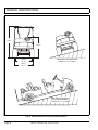
ACCELERATOR PEDAL
Unintentional movement
of the accelerator pedal
w il l r e l e a s e th e p a r k
brake and may cause the vehicle to move which could
result in severe injury or death.
!
Owner’s Manual and Service Guide
!
OPERATION AND SERVICE INFORMATION
Read all of manual to become thoroughly familiar with this vehicle. Pay particular attention to all Notes, Cautions and Warnings
With the key switch ‘ON’, depressing the accelerator
pedal starts the engine. When the pedal is released, the
engine will stop (Ref. Fig. 5 on page 3). To stop the vehicle more quickly, depress the service brake.
Frein de
stationnement
Klaxon
Accélérateur
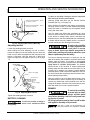
Fig. 6 Horn Button
Frein de service
OPERATING THE VEHICLE
Fig. 5 Accelerator and Brake Controls
If key switch is ‘ON’ and park brake is set, depressing the
accelerator inadvertently will release the park brake and
will cause the vehicle to move which could cause severe
injury or death.
Depressing the accelerator pedal will release the park
brake if it is engaged. This is a feature to assure the vehicle is not driven with the park brake engaged. Depressing the accelerator pedal is not the preferred method of
releasing the park brake.
Depressing the lower section of the brake
pedal is the preferred method of releasing the
park brake to assure the longest service life of brake components.
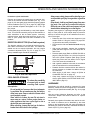
COMBINATION SERVICE AND PARK BRAKE
PEDAL WITH FRONT DISC BRAKES
(OPTIONAL)
The brake system consists of mechanically activated rear
drum brakes and hydraulically operated front disc
brakes. The front brakes are designed to operate under
hard braking conditions.
The front disc brakes are designed to activate as the
brake pedal reaches the ‘park or latch position’. Depressing the brake pedal further will increase the effectiveness
of the front brakes.
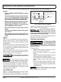
HORN
The horn is operated by pushing the horn button located
on the floor to the left of the brake pedal (Ref. Fig. 6 on
page 3) .
Improper use of the vehicle or the lack
of proper maintenance may result in
damage or decreased performance.
Read and understand the following warnings before
attempting to operate the vehicle.
To reduce the possibility
of severe injury or death
resulting from loss of
vehicle control, the following warnings must be
observed:
When driving vehicle, consider the terrain, traffic
conditions and the environmental factors which
effect the terrain and the ability to control the
vehicle.
Use extra care and reduced speed when driving
on poor surfaces, such as loose dirt, wet grass,
gravel, etc.
Stay in designated areas and avoid extremely
rough terrain.
Maintain a safe speed when driving down hill. Use
service brake to control speed when traveling
down an incline. A sudden stop or change of
direction may result in loss of control.
Slow down before and during turns. All turns
should be made at reduced speed.
Never drive vehicle up, down, or across an incline
that exceeds 14° (25% grade).
To reduce the possibility
!
! of severe injury or death
resulting from improper
vehicle operation, the following warnings must be
!
Owner’s Manual and Service Guide
!
Page 3
OPERATION AND SERVICE INFORMATION
Read all of manual to become thoroughly familiar with this vehicle. Pay particular attention to all Notes, Cautions and Warnings
observed:
Refer to GENERAL SPECIFICATIONS for seating
capacity.
To prevent inadvertent movement when the vehicle is to be left unattended, engage the park
brake, move direction selector to forward position, turn key to ‘OFF’ position and remove key.
Make sure that the direction selector is in correct
position before attempting to start the vehicle.
Always bring the vehicle to a complete stop
before shifting the direction selector.
Do not take vehicle out of ‘gear’ while in motion
(coast).
Check the area behind the vehicle before operating in reverse.
All occupants must be seated. Keep entire body
inside vehicle and hold on while vehicle is in
motion.
RUN-IN
Check for oil or fuel leaks that could have developed in
shipment from the factory. Avoid full throttle starts and
rapid acceleration until the engine has achieved operating temperature.
All engines consume more oil than normal during the first
hours of operation. As internal moving parts are run-in,
oil consumption should gradually decrease until the rate
of consumption stabilizes.
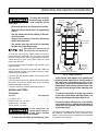
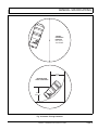
Check the oil level per the Periodic Service Schedule.
Add oil if the level on the dipstick indicates that oil is in
the add oil range (Ref. Fig. 14 on page 12).
Do not overfill engine. Too much oil
may cause smoking or allow oil to enter
the air filter enclosure.
Both the oil dipstick and fill cap must be in
place before operating the engine. Failure to
install the dipstick and fill cap will result in oil becoming contaminated and/or being discharged into the engine compartment.
The oil should be changed in accordance with the Periodic Service Schedule while the engine is warm. See
SERVICE AND MAINTENANCE for checking oil level
and changing oil procedures.
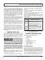
COLD STARTING
L
Mini
AJOUTER F
Ajouter
Maxi
Plage
de l'huile d'exploitation
sécurisée
Moteur chaud
Fig. 7 Check Oil Level on Dipstick
if required. Accelerate slowly and push the choke in completely when the engine runs smoothly.
Do not allow the starter to operate continuously for more than 10 seconds.
Allow 30 seconds between starting attempts. If the vehicle does
not start on the third attempt, turn the key switch off, set the park
brake and determine the cause of the problem.
If the vehicle had been running and the engine does not
start within 10 seconds, use the choke.
STARTING AND DRIVING
To reduce the possibility
of roll-back which could
result in severe injury or
vehicle damage, do not release service brake until
engine has started.
!
!
To operate vehicle:
• Apply the service brake, place the key in the key
switch and turn it to the ‘ON’ position.
• Move the direction selector to the direction
desired.
• Release the park brake by depressing the service
brake pedal until the park brake releases.
• Slowly depress the accelerator pedal to start the
engine. Release service brake when engine
starts.
• When the accelerator pedal is released, the ignition circuit is de-energized and the engine stops.
To stop the vehicle more quickly, depress the service brake pedal.
When the direction selector is in the reverse
position, a warning signal will sound to indicate
that the vehicle is ready to run in reverse.
Starting a cold engine may require use of the choke.
Depress the accelerator approximately 1" (2.5 cm) or
until the starter just begins to operate. Pull the choke out
Page 4
Niveau d'huile maximal
pour un moteur chaud
Ne pas remplir excessivement
Remplir le
moteur froid
jusqu'à ce point
Owner’s Manual and Service Guide
OPERATION AND SERVICE INFORMATION
Read all of manual to become thoroughly familiar with this vehicle. Pay particular attention to all Notes, Cautions and Warnings
STARTING THE VEHICLE ON A HILL
To reduce the possibility
!
! of roll-back which could
result in severe injury or
vehicle damage, do not release service brake until
engine has started.
Do not hold vehicle on hill by using
accelerator and engine. This will cause
premature and excessive wear to drive train components.
To reduce the possibility of permanent damage to the
drive system, it is important to prevent excessive rollback when starting the vehicle on a hill.
ous condition.
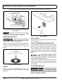
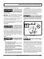
The fuel tank is located under the seat on the passenger
side of the vehicle (Ref. Fig. 8 on page 5). Fill the tank
with fresh, clean, automotive grade gasoline (Ref. Fig. 35
on page 23). High altitude or heavy use/load applications
may benefit from higher octane gasoline.
Do not use gasoline which contains Methanol.
Some fuels, called oxygenated or reformulated gasoline, are gasoline blended with
alcohols or ethers. Excessive amounts of these blends can damage the
fuel system or cause performance problems. If any undesirable operating symptoms occur, use gasoline with a lower percentage of alcohol or
ether.
Place left foot on service brake and release the park
brake. Depress accelerator with right foot and release
the service brake by lifting left foot.
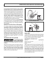
2,5 cm minimum
COASTING
CARBURANT
To reduce the possibility
of severe injury or death
from coasting at above
recommended speeds, limit speed with service brake.
!
!
On steep hills, it is possible for the vehicle to coast at
greater than normal speeds encountered on a flat surface. To reduce the possible loss of vehicle control and
severe drivetrain damage, speeds should be limited to no
more than the maximum governed speed on level ground
(see GENERAL SPECIFICATIONS). Limit speed by
applying service brake.
FUEL
!
Fig. 8 Fueling
BATTERY
!
To reduce the possibility
of severe injury or death
from improper fuel han-
dling:
Do not smoke near the fuel tank.
Do not refuel near open flame or electrical items
which could produce a spark.
Always handle gasoline in a well ventilated area.
Always wear eye protection to protect against
splashed fuel and fuel vapors.
Always allow adequate space for the expansion of
gasoline. Leave at least 1" (2.5 cm) space below
bottom of filler neck.
Inspect fuel cap, tank and other components for
leaks or deterioration that could cause a hazard-
Excessive use of accessories may drain
the battery and leave insufficient
reserve to start the vehicle.
The vehicle uses a combination starter/generator to both
start the engine and charge the battery. The engine will
not idle; therefore, the battery cannot be charged while
the vehicle is stopped. Do not operate accessory items
(such as accessory lights, radios, winch, etc.) excessively while the vehicle is stopped.
The generator is capable of supplying 35 amps; therefore, operation of all accessories could result in the discharge of the battery even though the engine is running
and the generator operating. Discharging the battery is
known as deep cycling. The battery is not a deep cycle
model, but is a starting battery. Multiple deep cycling will
result in the premature failure of the battery.
Owner’s Manual and Service Guide
Page 5
OPERATION AND SERVICE INFORMATION
Read all of manual to become thoroughly familiar with this vehicle. Pay particular attention to all Notes, Cautions and Warnings
If the vehicle battery has become discharged, it must be
charged using a 12 volt charger that is rated at 10 amps
or less and in accordance with all instructions provided
by the manufacturer of the charger.
LABELS AND PICTOGRAMS
Vehicles may be labeled with pictograms as a method of
conveying information or warnings. Appendix A illustrates and explains pictograms that may appear on the
vehicle. Not all pictograms shown in Appendix A will be
found on your vehicle.
!
Clean windshield with lots of water and a clean cloth.
Minor scratches may be removed using a commercial
plastic polish or Plexus® plastic cleaner available from
the service parts department.
Normal cleaning of vinyl seats and plastic or rubber trim
requires the use of a mild soap solution applied with a
sponge or soft brush and wipe with a damp cloth.
Removal of oil, tar, asphalt, shoe polish, etc. will require
the use of a commercially available vinyl/rubber cleaner.
SUN TOP AND WINDSHIELD
!
seals, plastics, seat material, body finish or electrical system. Do not use pressure in excess of 700 psi to wash
exterior of vehicle.
The sun top does not
provide protection from
roll over or falling
objects.
The windshield does not provide protection from tree
limbs or flying objects.
To prevent damage to the vehicle, do
not hold on to sun top struts and stand
on body panels.
The sun top and windshield provide some protection
from the elements; however, they will not keep the operator and passenger dry in a downpour. This vehicle is not
equipped with seat belts and the sun top has not been
designed to provide roll over protection. In addition, the
sun top does not protect against falling objects nor does
the windshield protect against flying objects and tree
limbs. Keep arms and legs inside of vehicle while it is
moving.
VEHICLE CLEANING AND CARE
The painted surfaces of the vehicle provide attractive
appearance and durable protection. Frequent washing
with lukewarm or cold water and mild detergent is
required to preserve the painted surfaces.
Occasional cleaning and waxing with non-abrasive products designed for ‘clear coat’ automotive finishes will
enhance the appearance and durability of the painted
surfaces.
Corrosive materials used as fertilizers or for dust control
can collect on the underbody of the vehicle. These materials will cause corrosion of underbody parts unless
flushed occasionally with plain water. Thoroughly clean
any areas where mud or other debris can collect. Sediment packed in closed areas should be loosened to ease
it’s removal, taking care not to chip or otherwise damage
paint.
If the engine does not start or runs improperly
after washing, remove the spark plug wires (by
pulling the spark plug boots, never the wires). Dry all connections with forced air. Reinstall the wires.
VEHICLE CLEANING
To reduce the possibility
!
! of severe injury or vehicle damage, read and
understand all instructions supplied by manufacturer
of pressure washer.
When pressure washing exterior of
vehicle, do not use pressure in excess
of 700 psi. To reduce the possibility of cosmetic damage, do not
use any abrasive or reactive solvents to clean plastic parts.
It is important that proper techniques and cleaning materials be used. Using excessive water pressure may
cause severe injury to operator or bystander, damage to
Page 6
REPAIR
LIFTING THE VEHICLE
Tool List
Qty. Required
Floor jack ..................................................................... 1
Jack stands.................................................................. 4
Chocks......................................................................... 4
‘
Some servicing operations may require the front wheels,
the rear wheels, or the entire vehicle be raised.
Owner’s Manual and Service Guide
OPERATION AND SERVICE INFORMATION
Read all of manual to become thoroughly familiar with this vehicle. Pay particular attention to all Notes, Cautions and Warnings
!
!
To reduce the possibility
of severe injury or death
from a vehicle falling
Centre de
l'essieu avant
from a jack:
Be sure the vehicle is on a firm and level surface.
Never get under a vehicle while it is supported by
a jack.
Use jack stands and test the stability of the vehicle on the stands.
Always place chocks in front and behind the
wheels not being raised.
Use extreme care since the vehicle is extremely
unstable during the lifting process.
Partie plane
du châssis
When lifting vehicle, position jacks and
jack stands at the areas indicated only.
To raise the entire vehicle, install chocks in front and
behind each front wheel (Ref. Fig. 9 on page 7). Center
the jack under the rear frame crossmember. Raise the
vehicle enough to place a jack stand under the outer
ends of the rear axle.
Lower the jack and test the stability of the vehicle on the
two jack stands.
Place the jack at the center of the front axle. Raise the
vehicle enough to place jack stands under the frame
crossmember as indicated.
Lower the jack and test the stability of the vehicle on all
four jack stands.
If only the front or rear of the vehicle is to be raised, place
the chocks in front and behind each wheel not being
raised to stabilize the vehicle.
Lower the vehicle by reversing the lifting sequence.
WHEELS AND TIRES
Tire Repair
Tool List
Qty. Required
Lug wrench, 3/4" ......................................................... 1
Impact socket, 3/4", 1/2" drive..................................... 1
Impact wrench, 1/2" drive............................................ 1
Torque wrench, 1/2" drive ........................................... 1
A ti r e e x p lo s i o n c a n
cause severe injury or
death. Never exceed
inflation pressure rating on tire sidewall.
To reduce the possibility of tire explosion, pres-
!
!
Extrémité
extérieure
de l'essieu
arrière
Vue du dessous du véhicule
Fig. 9 Lifting the Vehicle
surize tire with small amount of air applied intermittently to seat beads. Due to the low volume of
the small tires, overinflation can occur in seconds. Never exceed the tire manufacturer’s recommendation when seating a bead. Protect face
and eyes from escaping air when removing valve
core.
To reduce the possibility of severe injury caused
by a broken socket when removing wheels, use
only sockets designed for impact wrench use.
Use caution when inflating tires. Overinflation
could cause the tire to separate from the wheel or
cause the tire to explode, either of which could
cause severe injury.
Use caution when inflating tires. Due to the low volume of
the small tires, overinflation can occur in seconds. Overinflation could cause the tire to separate from the wheel
or cause the tire to explode.
Owner’s Manual and Service Guide
Page 7
OPERATION AND SERVICE INFORMATION
Read all of manual to become thoroughly familiar with this vehicle. Pay particular attention to all Notes, Cautions and Warnings
Tire inflation should be determined by the condition of the
terrain. See GENERAL SPECIFICATIONS section for
recommended tire inflation pressure. For outdoor applications with major use on grassy areas, the following
should be considered. On hard turf, it is desirable to have
a slightly higher inflation pressure. On very soft turf, a
lower pressure reduces the possibility of tires cutting into
the turf. For vehicles being used on paved or hard surfaces, tire inflation pressure should be in the higher
allowable range, but under no condition should inflation
pressure be higher than recommended on tire sidewall.
All four tires should have the same pressure for optimum handling characteristics. Be sure to install the valve
dust cap after checking or inflating.
The vehicle is fitted with low pressure tubeless tires
mounted on one piece rims; therefore, the most cost
effective way to repair a puncture in the tread is to use a
commercial tire plug.
Tire plug tools and plugs are available at most
automotive parts outlets and have the advantage of not requiring the tire be removed from the wheel.
If the tire is flat, remove the wheel and inflate the tire to
the maximum recommended pressure for the tire.
Immerse the tire in water to locate the leak and mark with
chalk. Insert tire plug in accordance with manufacturer’s
instructions.
To reduce the possibility
of severe injury, be sure
mounting/demounting
machine is anchored to floor. Wear OSHA approved
safety equipment when mounting/demounting tires.
!
!
If the tire is to be removed or mounted, the tire changing
machine manufacturer’s recommendations must be followed in order to reduce possibility of severe injury.
Wheel Installation
To reduce the possibility of component
damage, do not tighten lug nuts to more
than 85 ft. lbs. (115 Nm) torque.
It is important to follow the ‘cross sequence’
pattern when installing lug nuts. This will
assure even seating of the wheel against the hub.
With the valve stem to the outside, mount the wheel onto
the hub with lug nuts. Finger tighten lug nuts in a ‘cross
sequence’ pattern (Ref. Fig. 10 on page 8) . Tighten lug
nuts to 50 - 85 ft. lbs. (70 - 115 Nm) torque in 20 ft. lbs.
(30 Nm) increments following the ‘cross sequence’ pattern.
Page 8
Tire/wheel style
may vary
'Cross Sequence'
1
'Cross Sequence'
1
3
3
4
2
4
5
2
Ref Whi 2
Fig. 10 Wheel Installation
LIGHT BULB REPLACEMENT
To reduce the possibility of premature
bulb failure, do not touch new bulbs
with bare fingers. Use clean, dry tissue or paper towel to handle
the glass portion of the bulb.
For vehicles equipped with lights mounted below cowl,
locate bulb socket on backside of light bar (Ref. Fig. 11
on page 9) and turn bulb socket a quarter turn counterclockwise to unlock and pull out bulb. Insert new bulb
(Ref. CAPACITIES AND REPLACEMENT PARTS on
page 23) and rotate socket a quarter turn clockwise to
secure.
To replace the tail and brake light bulb, remove hardware
securing lens and remove lens (Ref. Fig. 12 on page 9).
Install replacement bulb (Ref. CAPACITIES AND
REPLACEMENT PARTS on page 23).
To replace the tail and brake light bulb, roll the rubber
bezel from around the edge of the taillight and remove
lens. Install replacement bulb and replace lens.
FUSE REPLACEMENT
To replace fuses, locate the fuse block under the driver
side seat. Pull out old fuse and replace with a new automotive type fuse. Headlight and taillight bulbs and fuses
are available from a local Distributor, an authorized
Branch or the Service Parts Department.
VEHICLE WITH A DISCHARGED BATTERY
!
Owner’s Manual and Service Guide
!
To reduce the possibility
of severe injury or death
OPERATION AND SERVICE INFORMATION
Read all of manual to become thoroughly familiar with this vehicle. Pay particular attention to all Notes, Cautions and Warnings
With the short running times associated with this kind of
vehicle, the generator is more than adequate to maintain
the battery charge level. The generator is not designed to
charge a discharged battery.
When engine starts, the clutches engage and cause
vehicle to move making ‘jump starting’ both dangerous
and impractical.
If the vehicle battery has become discharged, it must be
charged using a 12 volt charger that is rated at 10 amps
or less. Read and understand all instructions provided by
the manufacturer of the charger.
Feu
indicateur
Feu
indicateur
Clignotant
Clignotant
Il faut s’éloigner du logement
en caoutchouc pour le rouler
Phares
R G
Feu arrière/stop
Y R
Pare-chocs
arrière
Ref Hdr 1
Fig. 11 Headlight, Turn Signal & Marker Light Bulb
Replacement
from inadvertent motion, do not attempt to ‘jump
start’ a vehicle.
Ref Tlr 2
Fig. 12 Tail and Brake Light Bulb Replacement
The vehicle is equipped with a starter/generator and
does not idle. When starting the engine, the starter/generator functions as a starter and with the engine running,
it functions as a generator.
Owner’s Manual and Service Guide
Page 9
OPERATION AND SERVICE INFORMATION
Read all of manual to become thoroughly familiar with this vehicle. Pay particular attention to all Notes, Cautions and Warnings
TRANSPORTING VEHICLE
Always remove windshield before transporting.
Maximum speed with sun top installed is 50 mph
(80 kph).
TOWING
!
!
This vehicle is not
designed to be towed.
It is recommended that the vehicle be moved by placing
the entire vehicle on a trailer, flatbed truck or other suitable transport.
NEUTRAL LOCK
To prevent the driven clutch from turning the rear wheels
during service operations.
To operate:
Position direction selector lever between ‘F’ and ‘R’. Turn
key switch to ‘OFF’. Rotate pin on rear axle shift lever as
shown (Ref. Fig. 13 on page 10). The pin will snap into a
cavity in the differential case. When in this position, the
direction selector remains locked in the neutral position.
To unlock the direction selector, pull the pin out and
rotate until the pointed portion of the pin handle fits into
the detent position in the rear axle shift lever.
Débloqué
Débloqué
1
Languette
longue
Tirer sur le bouton puis le tourner
180° pour bloquer
2
Bloqué
Bloqué
1
2
Languette
courte
Tirer sur le bouton puis le tourner
180° pour débloquer
Fig. 13 Neutral Lock
HAULING
!
!
To reduce the possibility
of severe injury or death
while transporting vehi-
cle:
If the vehicle is to be transported at highway speeds, the
sun top must be removed and the seat bottom secured.
When transporting vehicle below highway speeds, check
for tightness of hardware and cracks in sun top at mounting points. Always remove windshield when transporting.
Always check that the vehicle and contents are adequately secured before transporting. The rated capacity
of the trailer or truck must exceed the weight of the vehicle (see GENERAL SPECIFICATIONS for vehicle
weight) and load. Lock the park brake and secure the
vehicle using ratchet tie downs.
SERVICE AND MAINTENANCE
!
To reduce the possibility
of severe injury or death
from improper servicing
techniques:
Do not attempt any type of servicing operations
before reading and understanding all notes, cautions and warnings in this manual.
Any servicing requiring adjustments to be made
to the powertrain while the engine is running
must be made with both drive wheels raised and
vehicle properly supported on jack stands.
To reduce the possibility of engine damage, never
operate vehicle at full throttle for more than 4 - 5
seconds while vehicle is in a ‘no load’ condition.
Wear eye protection when working on
the vehicle. Use extra care when working around batteries, or using solvents or compressed air.
To reduce the possibility of causing an electrical
arc, which could result in a battery explosion, turn
off all electrical loads from the battery before
removing battery wires.
Wrap wrenches with vinyl
tape to reduce the possibility
of a dropped wrench ‘shorting out’ a battery, which could result in an explosion.
Secure the vehicle and contents.
Never ride on vehicle being transported.
Page 10
!
Owner’s Manual and Service Guide
OPERATION AND SERVICE INFORMATION
Read all of manual to become thoroughly familiar with this vehicle. Pay particular attention to all Notes, Cautions and Warnings
Reduce the possibility of accidental starting by
removing and grounding spark plug wires and
disconnecting battery at negative terminal before
servicing.
The electrolyte in a battery is an acid solution
which can cause severe burns to the skin and
eyes. Treat all electrolyte spills to the body and
eyes with extended flushing with clear water.
Contact a physician immediately.
Any electrolyte spills should be neutralized with a
solution of 2 teaspoons (10 ml) sodium bicarbonate (baking soda) dissolved in 1 quart (1 liters) of
water and flushed with water.
Aerosol containers of battery terminal protectant
must be used with extreme care. Insulate metal
container to reduce the possibility of can contacting battery terminals which could result in an
explosion.
It is in the best interest of both vehicle owner and service
technician, to carefully follow the procedures recommended in this manual. Preventative maintenance,
applied at recommended intervals, is the best guarantee
for keeping the vehicle both dependable and economical.
To prolong vehicle life, some maintenance items must be serviced more frequently on vehicles used under severe driving conditions such
as extreme temperatures, extreme dust/debris conditions, frequent use with maximum load.
To access powertrain for routine maintenance, lift or
remove seat. For major repair, refer to appropriate Technician’s Repair and Service Manual.
Some service procedures may require the vehicle to be
lifted. Refer to LIFTING THE VEHICLE for proper lifting
procedure and safety information.
SERIAL NUMBER PLATE LOCATION
The serial number, manufacture date code label and supplemental information labels are on the vehicle. One is
placed on the body below the front, driver side of the
seat. The serial number, manufacture date code label
and supplemental information labels located on the chassis under the seat.
Design changes take place on an ongoing basis. In order
to obtain correct components for the vehicle, the manufacture date code, serial number and vehicle model must
be provided when ordering service parts. The serial number is permanently etched on the frame.
This vehicle will give years of satisfactory service, providing it receives regular maintenance. Refer to the Periodic
Service Schedule for appropriate service intervals (Ref.
Fig. 14 on page 12). Refer to Lubrication Points for
appropriate lubrication locations (Ref. Fig. 32 on page
21).
Owner’s Manual and Service Guide
Page 11
OPERATION AND SERVICE INFORMATION
Read all of manual to become thoroughly familiar with this vehicle. Pay particular attention to all Notes, Cautions and Warnings
PERIODIC SERVICE SCHEDULE
✓ Check
♦ Clean, Adjust, etc.
▲ Replace
To perform service that is listed in this schedule but not described in this manual, contact a local Service Representative or see the Repair and Service Manual for this vehicle.
NOTE: Some maintenance items must be serviced more frequently on vehicles used under severe driving conditions
DAILY
BEFORE USE:
✓ Check service brake general operation
✓ Check park brake function
✓ Check warning device function in reverse
✓ Check tire condition
✓ Check overall vehicle condition
WEEKLY
TIRES
✓
Examine for cuts, excessive wear and pressure
(See GENERAL SPECIFICATIONS)
WHEELS
✓
Check for bent rims, missing or loose lug nuts
FUEL GAUGE
✓
Check for proper operation (at fueling), and fuel cap vent is free of dirt
ENGINE OIL
✓
Check and add if required - DO NOT OVERFILL
STARTER/GENERATOR BELT
✓
Check for tension, wear, cracks
MONTHLY - 20 HOURS (includes items listed in previous table & the following)
WIRING
✓
Check all wiring for loose connections and broken/missing insulation
ACCELERATOR
✓
Check for smooth movement - DO NOT LUBRICATE CABLE
SERVICE BRAKE
(MECHANICAL BRAKES)
(HYDRAULIC BRAKES IF EQUIPPED)
✓
Conduct brake performance test
PARK BRAKE
✓
Check brake performance and adjust if required
CHOKE CABLE
✓
Check for smooth movement and adjustment - DO NOT LUBRICATE CABLE
CARBURETOR LINKAGE
✓
Check attachment, adjust as required
DIRECTION SELECTOR
✓
Check attachment, adjust as required
ENGINE
✓
Check for unusual noise, vibration, acceleration, oil leaks
COOLING FAN
✓
Check for build-up of foreign matter inside blower housing and fins, clean if
required
STEERING ASSEMBLY
✓
Check for abnormal play, tightness of all hardware
TIE ROD/LINKAGES
✓
Check for excessive play, bent components or loose connections
REAR AXLE
✓
Check for leakage, add SAE 30 oil as required
QUARTERLY - 50 HOURS (includes items listed in previous tables & the following)
Fig. 14 Periodic Service Schedule
Page 12
Owner’s Manual and Service Guide
OPERATION AND SERVICE INFORMATION
Read all of manual to become thoroughly familiar with this vehicle. Pay particular attention to all Notes, Cautions and Warnings
FRONT AXLE
✓
Check for damage to axle and loose or missing hardware
FRONT SHOCK ABSORBERS
✓
Check for oil leakage and loose fasteners
FRONT SPRINGS
✓
Check for loose hardware, cracks at attachments
FRONT WHEEL ALIGNMENT
✓
Check for unusual tire wear, align if required
✓
✓
♦
Check for bent/binding linkage rod
Check for damage or wear to latch arm or catch bracket
Lubricate as required, use light oil. DO NOT LUBRICATE CABLES OR BRAKE
LATCH
REAR SHOCK ABSORBERS
✓
Check for oil leakage, loose mounting hardware
ENGINE ELECTRICAL SYSTEM
✓
Check coil/spark plug wires for cracks/loose connections
FUEL SYSTEM
✓
✓
Check for leaks at tank, cap, system lines, filters, pump, carburetor
Check system lines for cracks/deterioration
THROTTLE/GOVERNOR LINKAGE
✓
Check operation and governed speed
HARDWARE AND FASTENERS
✓ Check for loose or missing hardware and components
♦ Tighten or replace missing hardware
PARK BRAKE
SEMI-ANNUAL - 125 HOURS (includes items listed in previous tables & the following)
BATTERY
♦
Clean battery & terminals
DIRECTION SELECTOR
✓
✓
Check for wear and smooth movement (lubricate shaft with light oil if required)
Check shift cable spring length at rear axle
KING PINS
✓
Check for excessive play and tightness of retaining nuts
STEERING ASSEMBLY
✓
Check bellows and pinion seal for damage or grease leakage
RACK END BALL JOINT
♦
Lubricate, use wheel bearing grease
REAR AXLE
✓
Check for unusual noise and loose or missing mounting hardware
AIR FILTER ELEMENT
✓
Check filter element, clean/replace as required
OIL FILTER
♦
Clean in solvent (at oil change), replace ‘O’ rings if required
ENGINE OIL
▲ Replace with SAE 10W-30 or 10W-40 that meets or exceeds SF, SG, CC oil,
DO NOT OVERFILL
DRIVE BELT
✓
Check for cracks, fraying and excessive wear
ANNUAL - 250-300 HOURS (includes items listed in previous tables & the following)
FRONT WHEEL BEARINGS
✓
Check and adjust as required, see Technician’s Repair and Service Manual
REAR AXLE
✓
Check lubricant, add lubricant (Ref. Fig. 30 on page 20) as required
SERVICE BRAKES
(HYDRAULIC BRKES)
♦
✓
✓
Clean and adjust, see Technician’s Repair and Service Manual
Check brake shoe linings, see Technician’s Repair and Service Manual
Check brake fluid
FUEL FILTER
▲ Replace
SPARK PLUGS
▲ Replace, gap new plugs
(Ref. CAPACITIES AND REPLACEMENT PARTS on page 23)
Fig. 14 Periodic Service Schedule
Owner’s Manual and Service Guide
Page 13
OPERATION AND SERVICE INFORMATION
Read all of manual to become thoroughly familiar with this vehicle. Pay particular attention to all Notes, Cautions and Warnings
MUFFLER/EXHAUST
✓
Check mounting hardware; check for leaks at head and muffler gaskets
VALVES
✓
Check cold (intake/exhaust) per Technician’s Repair and Service Manual
500 HOURS (includes items listed in previous tables & the following)
TIMING BELT
✓ Check tension and for signs of wear/damage, replace if worn or damaged
CARBURETOR
♦ Clean
CYLINDER HEAD AND PISTONS
♦ Remove carbon from cylinder head and pistons
✓ Check valve seats for carbon buildup and clean as required
Fig. 14 Periodic Service Schedule
TIRE INSPECTION
Tire condition should be inspected per the Periodic Service Schedule (Ref. Fig. 14 on page 12). Inflation pressures should be checked when the tires are cool. Be sure
to install the valve dust cap after checking or inflating.
CHECKING THE OIL LEVEL
Do not overfill engine. Too much oil
may cause engine to smoke or spark
plug fouling.
When adding oil between oil changes, do not
mix brands and viscosity grades of oil. Both the
oil dipstick and fill cap must be in place before operating the
engine. Failure to install the dipstick and fill cap will result in oil
becoming contaminated and/or oil being discharged into the
engine compartment.
The oil should be checked with the engine warm. The
vehicle must be on a level surface with the park brake
engaged. Allow adequate time for oil to drain into the
crankcase before checking.
Remove the dipstick and wipe off the entire area indicated with a lint free cloth (Ref. Fig. 15 on page 14).
The engine can be operated safely as long as oil is within
the safe operating range as indicated on the dipstick. Do
not operate vehicle if oil level is below the safe area
indicated on the dipstick (Ref. Fig. 16 on page 14).
Niveau d'huile maximal
pour un moteur chaud
Ne pas remplir excessivement
Remplir le
moteur froid
jusqu'à ce point
L
AJOUTER F
Ajouter
Maxi
Plage
de l'huile d'exploitation
sécurisée
Moteur chaud
Mini
Fig. 16 Check Oil Level on Dipstick
Oil should be added to bring the level into the safe operating range. Do not overfill. Check that the oil fill cap
and dipstick are firmly in place.
CHANGING THE OIL
Tool List
Qty. Required
Socket, 10 mm, 3/8" drive............................................ 1
Ratchet, 3/8" drive ....................................................... 1
Extension, 8", 3/8" drive .............................................. 1
L
F
Oil drain pan ................................................................ 1
For maximum performance and longevity, the engine oil
should be replaced every 125 hours of operation or semiannually, whichever comes first.
Fig. 15 Clean Entire Dipstick
Insert the dipstick fully into the dipstick hole and remove.
Examine the level of oil on the dipstick.
Page 14
The selection of oil is dependent upon the service that
the vehicle will perform. Most vehicles require 10W-30
oil, whereas vehicles used at capacity or near capacity
load applications will require 10W-40 oil after run-in (Ref.
Fig. 17 on page 15).
Owner’s Manual and Service Guide
OPERATION AND SERVICE INFORMATION
Read all of manual to become thoroughly familiar with this vehicle. Pay particular attention to all Notes, Cautions and Warnings
Grand joint torique
SERVICE INTENSIF
Filtre à huile
10W-40
10W-30
Petit joint torique à l'intérieur
du bout du filtre à huile
SERVICE LEGER
10W-30
Fig. 19 Remove Oil Filter
F
0
-20
C 0 -30
Ref Ovc 1
0
-20
20
40
60
80
-10
0
10
20
(TEMPERATURE D'AIR)
100
30
40
Fig. 17 Oil Viscosity Chart
To reduce the possibility
of severe injury, wear
rubber gloves to protect
skin from exposure to hot, used oil and degreaser.
These fluids contain chemicals known to cause cancer.
!
!
At each oil change, thoroughly inspect filter before cleaning. At the first oil change, metal chips and lint may be
found. This is normal, resulting from engine run-in. At
subsequent oil changes, the presence of metal chips
may indicate possible engine damage.
Wear eye protection to reduce the possibility of splashed solvent contacting the
eyes when cleaning oil filter.
Clean the filter by washing in any shop degreaser and
brushing the metal screen clean with a soft brush (Ref.
Fig. 20 on page 15).
The oil should be changed with the engine warm. Park the vehicle on a level surface, engage the park brake and remove the
key. Place a drain pan under the engine. Wipe the top of the
engine clean with a cloth (Ref. Fig. 18 on page 15). Remove the
oil fill cap.
Chapeau de
remplissage d'huile
Joint torique
Fig. 20 Clean Oil Filter
Blow out the filter with low pressure air 30 psi (210 kPa)
or less from no closer than 3" (8 cm) and allow to air dry
(Ref. Fig. 21 on page 16).
Fig. 18 Clean Top of Engine
Clean the area around the filter. Oil drainage is accomplished by removing the three bolts securing the oil filter
to the engine. Remove the filter by pulling it from the
engine and allow the oil to drain. The ‘O’ rings may
remain on the engine or the filter (Ref. Fig. 19 on page
15).
Wipe the area around the filter mount with a clean, lint
free cloth and inspect both filter ‘O’ rings for damage;
replace if necessary. Install the filter into the engine. The
filter engages over a short nipple in the engine. The filter
should slide easily onto the nipple and seat against the
engine using light hand pressure only. Align the holes in
the filter mounting plate with the holes in the engine.
Install and hand tighten the bolts before tightening them
firmly.
Owner’s Manual and Service Guide
Page 15
OPERATION AND SERVICE INFORMATION
Read all of manual to become thoroughly familiar with this vehicle. Pay particular attention to all Notes, Cautions and Warnings
Check the oil level again with the vehicle on level ground.
Oil should be added to bring the level into the safe operating range. Do not overfill. The engine can be operated
safely as long as the oil is within the safe operating range
as indicated on the dipstick. Do not operate vehicle if
oil level is below the safe area indicated on the dipstick.
8 cm
minimum
Joint torique
STARTER/GENERATOR BELT TENSION
Tool List
Maximum : 210 kPa
Fig. 21 Blowing Out Oil Filter
Add slightly less than 1 1/2 quarts (1.4 liters) to allow for
possible residual oil left in engine (Ref. Fig. 22 on page
16). The oil must be high quality oil that meets or
exceeds API SF, SG, CC standards (Ref. Fig. 35 on page
23). Check oil level on dipstick. If necessary, continue to
add oil slowly and allow time for oil to flow down into
engine. Check oil level on dipstick. Do not overfill.
Do not overfill engine. Too much oil
may cause smoking or allow oil to enter
the air filter enclosure.
Both the oil dipstick and fill cap must be in
place before operating the engine. Failure to
install the dipstick and fill cap will result in oil being discharged
into the engine compartment.
Qty. Required
Belt tension gauge....................................................... 1
Wrench, 3/4" ................................................................ 1
Wrench, 9/16" .............................................................. 2
Ratchet, 3/8" drive ....................................................... 1
Socket, 3/4", 3/8" drive ................................................ 1
The starter/generator belt tension should be checked
after the first 15 - 20 hours and set to 75 - 80 lbs. (34 - 36
kg).
A loose belt can cause audible vibration and
squeal.
Tighten a new starter/generator belt (Ref. Fig. 23 on
page 16) to 90 - 110 lbs. (41-50 kg) tension when a
gauge is applied half way between the two pulleys (Ref.
Fig. 23 on page 16).
Joint toriqu
Fig. 23 Checking Belt Tension with Gauge
A new belt may be checked manually. A maximum
deflection of 3/8" (10 mm) is acceptable (Ref. Fig. 24 on
page 17).
Fig. 22 Add Engine Oil
Inspect oil fill cap ‘O’ ring and replace if necessary. Install
the oil fill cap. Run the vehicle for one or two minutes and
check the filter for oil leaks.
Page 16
Tighten an existing belt to 75 - 80 lbs. (34 - 36 kg) tension using the same technique and inspect for cracking
or wear. A maximum deflection of 1/2" (13 mm) is acceptable.
Owner’s Manual and Service Guide
OPERATION AND SERVICE INFORMATION
Read all of manual to become thoroughly familiar with this vehicle. Pay particular attention to all Notes, Cautions and Warnings
To reduce the possibility of damage to electrical components
while cleaning, do not use a pressure washer.
Flexion maxi admissible : 10 mm
(nouvelle courroie)
Cleaning should take place per the Periodic Service
Schedule (Ref. Fig. 14 on page 12).
Flexion maxi admissible : 13 mm
(ancienne courroie)
When cleaning the outside of the battery and terminals,
first spray with a solution of sodium bicarbonate (baking
soda) and water to neutralize any acid deposits before
rinsing with clear water.
Fig. 24 Checking Belt Tension Manually
Adjusting the Belt
Use of a water hose without first neutralizing any acid,
will move acid from the top of the battery to another area
of the vehicle or storage facility where it will attack the
metal structure or the concrete/asphalt floor. Additionally,
a residue will be left on the battery which is conductive
and will contribute to the discharge of the battery.
To reduce the possibility
of battery explosion that
could result in severe
injury or death, do not use metallic spray wand to
clean battery and keep all smoking materials, open
flame or sparks away from the battery.
!
Loosen the starter/generator pivot bolt.
While holding the lower adjusting nut with a wrench,
loosen the upper jam nut with another wrench. Move the
lower nut up or down the adjustment bolt until proper belt
tension is achieved. Hold the lower nut in place and
tighten the upper jam nut against it (Ref. Fig. 25 on page
17).
Boulon de réglage
Contre-écrou
Vis de réglage
!
The correct cleaning technique is to spray the top and
sides of the battery with a solution of sodium bicarbonate
(baking soda) and water. This solution is best applied
with a garden type sprayer equipped with a non metallic
spray wand or a plastic spray bottle. The solution
should consist of the amounts of sodium bicarbonate
(baking soda) and clear water shown below (Ref. Fig. 26
on page 18). In addition to the battery, special attention
should be paid to metal components adjacent to the battery which should also be sprayed with the sodium bicarbonate (baking soda) solution.
Allow the solution to sit for at least three minutes; use a
soft bristle brush or cloth to wipe the tops of the battery to
remove any residue that could contribute to the self discharge of the battery. Rinse the entire area with low pressure clear water. Do not use a pressure washer.
BRAKES
Fig. 25 Adjusting Belt Tension
Tighten the starter/generator pivot bolt.
BATTERY CLEANING
To reduce the possibility of damage to
vehicle or floor, neutralize acid before
rinsing battery.
To reduce the possibility
of severe injury or death,
always evaluate pedal
travel before operating a vehicle to verify some braking function is present.
All driving brake tests must be done in a safe location
with regard for the safety of all personnel.
!
!
Over time, a subtle loss of performance may
take place; therefore, it is important to establish
Owner’s Manual and Service Guide
Page 17
OPERATION AND SERVICE INFORMATION
Read all of manual to become thoroughly familiar with this vehicle. Pay particular attention to all Notes, Cautions and Warnings
Accélérer
6 litres
d’eau claire
à la
1 litre
d’eau claire
Surface vitesse
60 ml de
bicarbonate
de soude
carrelée au sol
sèche
maximale
10 ml de
bicarbonate
de soude
OU
Tige non
métallique
Vaporisateur
de type
jardinage
7,5 litres
Atomiseur
en
plastique
Ref Pns 1
Fig. 26 Preparing Acid Neutralizing Solution
the standard with a new vehicle.
The Periodic Brake Performance Test should be performed regularly (Ref. Fig. 14 on page 12) as an evaluation of braking system performance or if there is a
decrease in braking effectiveness. It is useful as a
method of identifying subtle loss of performance over
time.
Periodic Brake Test for Mechanical Brakes
The purpose of this test is to compare the braking performance of the vehicle to the braking performance of new
or ‘known to be good’ vehicles or to an established
acceptable stopping distance. Actual stopping distances
will be influenced by weather conditions, terrain, road
surface condition, actual vehicle weight (accessories
installed) and vehicle speed. No specific braking distance
can be reliably specified. The test is conducted by latching the parking brake to eliminate different pedal pressures and to include the affects of linkage misadjustment.
Establish the acceptable stopping distance by testing a
new or ‘known to be good’ vehicle and recording the
stopping location or stopping distance. For fleets of vehicles, several vehicles should be tested when new and
the range of stopping locations or distances recorded.
Serrer le
frein de
stationnement
(PARK)
Zone de
freinage
moyenne
Ligne ou balise
Si la distance d'arrêt
du véhicule dépasse
1,2 m de la distance
d'arrêt admise, ou
s'il tire d'un côté, le
véhicule doit être mis
hors service et
inspecté par un
mécanicien compétent
Fig. 27 Typical Brake Performance Test
Over time, a subtle loss of performance may
take place; therefore, it is important to establish
the standard with a new vehicle.
Page 18
Ligne ou balise
Owner’s Manual and Service Guide
OPERATION AND SERVICE INFORMATION
Read all of manual to become thoroughly familiar with this vehicle. Pay particular attention to all Notes, Cautions and Warnings
Drive the vehicle at maximum speed on a flat, dry, clean,
paved surface (Ref. Fig. 27 on page 18). Quickly depress
the brake pedal to latch the parking brake at the line or
marker in the test area and remove foot from pedal. The
vehicle should stop aggressively. The wheel brakes may
or may not lock. Observe the vehicle stopping location or
measure the vehicle stopping distance from the point at
which the brakes were latched. The vehicle should stop
within the ‘normal’ range of stopping distances. If the
vehicle stops more than 4 ft. (1.2 m) beyond the acceptable stopping distance or pulls to one side, the vehicle
has failed the test and should be tested again.
If the vehicle fails the second test, it should immediately
be removed from service. The vehicle must be inspected
by a qualified mechanic who should refer to the TROUBLESHOOTING section in the Technicain’s Repair and
Service Manual.
Fig. 28 Cleaning Air Intake
Hydraulic Front Disc Brakes (If Equipped)
For vehicles equipped with hydraulic front disc brakes,
check master cylinder fluid per PERIODIC SERVICE
SCHEDULE or if there is a decrease in braking effectiveness. Inspect components for damage or wear. It is
unlikely that fluid will need to be added unless there is a
leak in the system. Raise the front of the vehicle (See
raising the vehicle). Remove passenger side wheel/tire.
Carefully wipe off dirt and debris from master cylinder
and cap before opening. Remove the cap. Using a
mechanics mirror, check to see that fluid is no more than
1/4" below top of reservoir. Add DOT 3 or 4 fluid as
required.
AIR INTAKE AND COOLING FINS
To prevent possible
!
! burns, engine parts
should be kept clean to
reduce risk of overheating and ignition of accumulated debris.
After every off road use, allow to cool and then check for
a build up of dirt and debris in the air intake and cooling
fins. Dirt and debris may clog the engine’s air cooling
system. Clean areas shown to prevent engine damage
(Ref. Fig. 28 on page 19) (Ref. Fig. 29 on page 19). Keep
linkages, springs and controls clean. Keep area around
muffler free of any combustible material.
Fig. 29 Cleaning the Cooling Fins
REAR AXLE
The rear axle is provided with a lubricant level check plug
located on the driver side at the rear of the housing (Ref.
Fig. 30 on page 20). Unless leakage of rear axle lubricant
is evident, an annual lubricant check is sufficient.
Checking the Lubricant Level
Tool List
Qty. Required
Socket, 13 mm, 3/8" drive ........................................... 1
Ratchet, 3/8" drive ....................................................... 1
Funnel ......................................................................... 1
Clean the area around the check and fill plugs. Remove
the check plug. The correct lubricant level is just below
the bottom of the threaded hole (Ref. Fig. 30 on page
20). If lubricant is to be added, remove the fill plug and
add lubricant using a funnel. Add lubricant slowly until
lubricant starts to seep from the check plug hole. Install
the check plug and the fill plug. In the event that the lubricant is to be replaced, a drain plug is provided at the bottom of the differential housing.
Owner’s Manual and Service Guide
Page 19
OPERATION AND SERVICE INFORMATION
Read all of manual to become thoroughly familiar with this vehicle. Pay particular attention to all Notes, Cautions and Warnings
accessible by unsnapping top clips from the air box and
swinging the cover open. Remove cover and air filter element (Ref. Fig. 31 on page 20). Clean inside of cover and
enclosure. Install the new element in the same way the
old filter was removed, being sure that the filter seal is
correctly installed. Insert cover into the lower portion of
the enclosure and swing it up into place. Squeeze housing together and secure with top clips. Be sure cover fits
under tabs and all clips are fastened securely.
Bouchon
de contrôle
Cleaning the Air Filter Element
Do not use compressed air to clean the
air filter; doing so will damage the filter
which may result in damage to the engine.
Bouchon de remplissage Bouchon de vidange
Fig. 30 Add, Check and Drain Rear Axle Lubricant
AIR CLEANER INSPECTION AND
REPLACEMENT
If the element is in acceptable condition, loose dirt may
be removed by tapping the filter lightly. Do not use oil on
the filter element or any part of the unit.
LUBRICATION
Do not use more than three (3) pumps
of grease in any grease fitting at any
one time. Excess grease may cause grease seals to fail or
grease migration into areas that could damage components.
Putting more than three pumps of grease in a grease fitting could damage grease seals and cause premature
bearing failure (Ref. Fig. 32 on page 21).
Les côtés avant et arrière
des languettes peuvent être
lubrifiés avec de la vaseline
Les côtés avant et arrière
du joint du filtre à air peuvent ê
lubrifiés avec de la vaseline
Joint à rotule
de crémaillère
Fig. 31 Air Cleaner
Ref Lub 1
To reduce the possibility of engine
damage, be sure that bottom tabs of
cover are installed in enclosure and top of cover is installed
under top tabs. Secure all spring clips.
The air cleaner unit on the vehicle is a dry unit.
Do not use oil on the filter element or any part
of the unit. To aide installation and sealing, petroleum jelly may
be applied to back side of cover tabs and each side of filter
seal.
The air cleaner is attached to the engine and may be
accessed by raising the seat. Inspect and replace air filter in accordance with the Periodic Service Schedule
(Ref. Fig. 14 on page 12). The air cleaner element is
Page 20
Vue du dessous du véhicule
Fig. 32 Lubrication Points
SPARK PLUGS
Tool List
Qty. Required
Spark plug socket, 13/16", 1/2" drive ........................... 1
Ratchet, 1/2" drive ....................................................... 1
Plug gauge, wire type .................................................. 1
Anti-seize compound ................................................ AR
Torque wrench, 1/2" drive, ft. lbs. ................................ 1
Owner’s Manual and Service Guide
Use care not to over-tighten the plug.
Over-tightening can cause damage to
OPERATION AND SERVICE INFORMATION
Read all of manual to become thoroughly familiar with this vehicle. Pay particular attention to all Notes, Cautions and Warnings
the aluminum cylinder head threads.
Remove and inspect the spark plugs at intervals indicated in the Periodic Service Schedule (Ref. Fig. 14 on
page 12). All new spark plugs should be properly gapped
before installation (Ref. Fig. 35 on page 23). Apply a light
coat of anti-seize compound and tighten to 18 ft. lbs. (24
Nm) torque.
Fouled spark plugs are indicated by a wet, black appearance. This could be caused by a dirty air filter element or
other restrictions in the air intake system. Incorrectly
adjusted valves, spark plug wires which are in poor condition or poor quality fuel could also contribute to the
problem.
DIRECTION SELECTOR (Dual Cable system)
The direction selector is a mechanical device that operates cables connected to the rear axle. The cables are
sealed and do not require lubrication, but may require
occasional adjustment (Ref. Fig. 33 on page 21). The
factory installed length should be maintained.
Longueur
établie
en usine
3,5 cm
POINT MORT
Fig. 33 Shift Cable Adjustment
PROLONGED STORAGE
!
!
To reduce the possibility
of severe injury or death
resulting from a possi-
ble explosion:
Do not handle fuel in an area that is not adequately ventilated. Do not smoke near the fuel tank or
refuel near open flame or electrical items which
could produce a spark.
Store vehicle in a clean, dry area. Do not store in
same area as a stove, furnace, water heater, or
other appliance that uses a pilot light or has a
device that can create a spark.
When refueling, inspect the fuel cap for leaks or
breaks that could result in fuel spillage.
Always wear safety glasses while refueling to prevent possible eye injury from gasoline or gasoline
vapor.
Keep hands, clothing and jewelry away from moving parts. Use care not to contact hot objects.
Raise the rear of the vehicle and support on jack
stands before attempting to run the engine.
Preparing the engine for a prolonged storage period (30
days or more) calls for a few simple steps to prevent a
build up of varnish and gum in the carburetor and corrosion in the engine.
• Raise the rear of the vehicle and support on jack
stands. Refer to ‘Lifting the Vehicle’ for proper lifting procedure and safety information.
• Disconnect the fuel hose at the fuel tank and plug
hose.
• With proper ventilation, depress the accelerator
pedal and allow engine to run until it stops due to
lack of fuel.
• Remove spark plugs (Refer to SPARK PLUGS on
page 21) and pour about 1 oz. (30 ml) of engine oil
into each cylinder. Replace spark plugs, ground
spark plug wires and use starter to turn engine
over a few seconds to distribute oil.
• Add a gasoline additive to the tank in accordance
with the manufacturer’s recommendations.
• Reattach fuel line to tank and drive the vehicle for
several minutes to circulate the additive through
the carburetor.
• While engine is still warm, change oil (Refer to
CHANGING THE OIL on page 14).
• Clean body, chassis and engine of debris, mud,
chaff or grass (Refer to AIR INTAKE AND COOLING FINS on page 19).
HARDWARE
Periodically, the vehicle should be inspected for loose
fasteners. Fasteners should be tightened in accordance
with the Torque Specifications table (Ref. Fig. 34 on page
22).
Use care when tightening fasteners and refer to the
Technician’s Repair and Service Manual for specific
torque values.
Generally, three grades of hardware are used in the vehicle. Grade 5 hardware can be identified by the three
marks on the hexagonal head and grade 8 hardware is
identified by 6 marks on the head. Unmarked hardware is
Grade 2 (Ref. Fig. 34 on page 22).
Owner’s Manual and Service Guide
Page 21
OPERATION AND SERVICE INFORMATION
Read all of manual to become thoroughly familiar with this vehicle. Pay particular attention to all Notes, Cautions and Warnings
VALEURS DE COUPLE FT. LBS. (Nm)
A moins d’indication contraire dans le texte, serrer toute la boulonnerie de montage conformément à ce tableau.
Le tableau ci-dessous donne des valeurs de couple à l’état «humide». Les éléments de fixation plaqués
ou lubrifiés à l’installation sont dits «humides» et ne demandent que 80 % environ du couple nécessaire aux fixations «sèches».
1/4"
5/16"
3/8"
7/16"
1/2"
9/16"
5/8"
3/4"
7/8"
1"
Qualité 2
4
(5)
8
(11)
15
(20)
24
(33)
35
(47)
55
(75)
75
(102)
130
(176)
125
(169)
190
(258)
Qualité 5
6
(8)
13
(18)
23
(31)
35
(47)
55
(75)
80
(108)
110
(149)
200
(271)
320
(434)
480
(651)
Qualité 8
6
(8)
18
(24)
35
(47)
55
(75)
80
(108)
110
(149)
170
(230)
280
(380)
460
(624)
680
(922)
TAILLE DU BOULON
TAILLE DU BOULON
M4
M5
M6
M8
M10
M12
M14
Classe 5.8
(Qualité 2) 5.8
1
(2)
2
(3)
4
(6)
10
(14)
20
(27)
35
(47)
55
(76.4)
Classe 8.8
(Qualité 5) 8.8
2
(3)
4
(6)
7
(10)
18
(24)
35
(47)
61
(83)
97
(131)
Classe 10.9
(Qualité 8) 10.9
3
(4)
6
(8)
10
(14)
25
(34)
49
(66)
86
(117)
136
(184)
Ref Tsp 1
Fig. 34 Torque Specifications
Page 22
Owner’s Manual and Service Guide
OPERATION AND SERVICE INFORMATION
Read all of manual to become thoroughly familiar with this vehicle. Pay particular attention to all Notes, Cautions and Warnings
CAPACITIES AND REPLACEMENT PARTS
Réservoir de carburant
22,5 litres, indice d'octane : 87
Huile moteur
1,4 litre
Filtre à huile
N/P 26591-G01
Filtre à air
N/P 72368-G01
Bougies de préchauffage
NGK BPR5ES (N/P 25523-G4)
Espace : 0,71 – 0,76 mm
Courroie de starter/générateur N/P 26414-G01
Courroie d'embrayage
N/P 72054-G01
Huile d'essieu arrière
1,2 litre
Fusible
15 A (N/P 18392-G1)
Ampoule de phare
#894 (N/P 74004-G01)
Ampoule de feu indicateur #912 (N/P 74005-G01)
Ampoule de clignotant
#921 (N/P 74006-G01)
Ampoule de feu du hayon
#1157 (N/P 21759-G1)
Ref Cap 4
Fig. 35 Capacities and Replacement Parts
Owner’s Manual and Service Guide
Page 23
OPERATION AND SERVICE INFORMATION
Read all of manual to become thoroughly familiar with this vehicle. Pay particular attention to all Notes, Cautions and Warnings
Notes:
Page 24
Owner’s Manual and Service Guide
GENERAL SPECIFICATIONS
GENERAL SPECIFICATIONS
Owner’s Manual and Service Guide
Page 25
GENERAL SPECIFICATIONS
SHUTTLE 2
GASOLINE POWERED CARGO CARRIER
WEIGHT (dry fuel tank)............................................................ 1000 lbs. (450 kg)
TIRES ...................................................................................... 18 x 8.50 x 8 (LINKS 4 ply)
TIRE PRESSURE .................................................................... 18 - 22 psi (124 - 152 kPa)
LOAD CAPACITY (including operator, passengers,
cargo and accessories) .............................. 1200 lbs. (544 kg)
CARGO BED............................................................................ 42.5 in. (108 cm) width
32 in. (80 cm) length
12 in. (31 cm) height
CHASSIS ................................................................................. Welded high yield strength tubular steel with Durashield™ Powder
Coat paint
BODY & FINISH....................................................................... Durashield™ body of automotive quality injection molded TPE
(thermoplastic elastomer). Automotive color coat/clear coat finish
SAFETY ................................................................................... Dash mounted key switch, reverse warning indicator, ‘deadman’
accelerator control, integral handgrip on hip restraints, manual forward/
reverse selector and electric horn
LIGHTING PACKAGE .............................................................. Optional Headlights, taillights, brake lights, optional turn signals
BRAKES ................................................................................. Dual rear wheel mechanical, self-adjusting drum brakes. Combination
service / park brake with automatic parking brake release (accelerator
kick-off). Optional hydraulic front disc brakes
FRONT SUSPENSION ............................................................ Leaf springs with hydraulic shock absorbers
REAR SUSPENSION............................................................... Leaf springs with hydraulic shock absorbers
STEERING............................................................................... Self-compensating single reduction rack and pinion
DASH PANEL........................................................................... Four drink holders of scuff resistant thermoplastic
SEATING..................................................................................Formed, fabric-backed vinyl covers over cushion foam. Seating for two
occupants per seat
ENGINE ................................................................................... 11 HP (8.2 kw) rated, 4 cycle, 350cc twin cylinder air cooled
VALVE TRAIN ..........................................................................Overhead valve, overhead cam, belt drive
LUBRICATION .........................................................................Pressurized oil system, washable permanent filter
BALANCER.............................................................................. Internal counter rotating balance shaft
IGNITION ................................................................................. Solid state, electronic timing advance and rpm limiter
CARBURETOR ........................................................................ Fixed jet float bowl with remote pulse fuel pump
AIR CLEANER .........................................................................Engine mounted with replaceable dry cartridge element
DRIVE TRAIN ..........................................................................Automatic, continuously variable transmission (CVT), forward and
reverse
ELECTRICAL SYSTEM ........................................................... External starter/generator, solid state regulator, 12 volt maintenance
free battery, 360 CCA, 51 minute reverse
TRANSAXLE............................................................................ High efficiency differential with helical gears, 13.32:1 ratio, ground
speed governor, forward and reverse
FUEL SYSTEM ........................................................................ 6 gallon (22.5 liters) capacity tank with dash mounted electric fuel
gauge
SPEED ..................................................................................... 12 - 15 mph (19 - 24 kph)
* Specifications subject to change without notice
Page 26
Owner’s Manual and Service Guide
GENERAL SPECIFICATIONS
SHUTTLE 4
GASOLINE POWERED PERSONNEL / CARGO CARRIER
WEIGHT (dry fuel tank)............................................................ 1014 lbs. (460 kg)
TIRES ...................................................................................... 18 x 8.50 x 8 (LINKS 4 ply)
TIRE PRESSURE .................................................................... 18 - 22 psi (124 - 152 kPa)
LOAD CAPACITY (including operator, passengers,
cargo and accessories) .............................. 1200 lbs. (544 kg)
CARGO BED ........................................................................... 42.5 in. (108 cm) width
32 in. (80 cm) length
12 in. (31 cm) height
CHASSIS ................................................................................. Welded high yield strength tubular steel with Durashield™ Powder
Coat paint
BODY & FINISH....................................................................... Durashield™ body of automotive quality injection molded TPE
(thermoplastic elastomer). Automotive color coat/clear coat finish
SAFETY ................................................................................... Dash mounted key switch, reverse warning indicator, ‘deadman’
accelerator control, integral handgrip on hip restraints, manual forward/
reverse selector and electric horn
LIGHTING PACKAGE.............................................................. Optional Headlights, taillights, brake lights, optional turn signals
BRAKES ................................................................................. Dual rear wheel mechanical, self-adjusting drum brakes. Combination
service / park brake with automatic parking brake release (accelerator
kick-off). Optional hydraulic front disc brakes
FRONT SUSPENSION ............................................................ Leaf springs with hydraulic shock absorbers
REAR SUSPENSION .............................................................. Leaf springs with hydraulic shock absorbers
STEERING .............................................................................. Self-compensating single reduction rack and pinion
DASH PANEL .......................................................................... Four drink holders of scuff resistant thermoplastic
SEATING ................................................................................. Formed, fabric-backed vinyl covers over cushion foam. Seating for two
occupants per seat
ENGINE ................................................................................... 11 HP (8.2 kw) rated, 4 cycle, 350cc twin cylinder air cooled
VALVE TRAIN .......................................................................... Overhead valve, overhead cam, belt drive
LUBRICATION ......................................................................... Pressurized oil system, washable permanent filter
BALANCER ............................................................................. Internal counter rotating balance shaft
IGNITION................................................................................. Solid state, electronic timing advance and rpm limiter
CARBURETOR........................................................................ Fixed jet float bowl with remote pulse fuel pump
AIR CLEANER......................................................................... Engine mounted with replaceable dry cartridge element
DRIVE TRAIN .......................................................................... Automatic, continuously variable transmission (CVT), forward and
reverse
ELECTRICAL SYSTEM ........................................................... External starter/generator, solid state regulator, 12 volt maintenance
free battery, 360 CCA, 51 minute reverse
TRANSAXLE ........................................................................... High efficiency differential with helical gears, 13.32:1 ratio, ground
speed governor, forward and reverse
FUEL SYSTEM ........................................................................ 6 gallon (22.5 liters) capacity tank with dash mounted electric fuel
gauge
SPEED..................................................................................... 12 - 15 mph (19 - 24 kph)
* Specifications subject to change without notice
Owner’s Manual and Service Guide
Page 27
GENERAL SPECIFICATIONS
SHUTTLE 6
GASOLINE POWERED PERSONNEL CARRIER
WEIGHT (dry fuel tank)............................................................ 1014 lbs. (460 kg)
TIRES ...................................................................................... 18 x 8.50 x 8 (LINKS 6 ply)
TIRE PRESSURE .................................................................... 18 - 22 psi (124 - 152 kPa)
LOAD CAPACITY (including operator, passengers,
cargo and accessories) .............................. 1200 lbs. (544 kg)
CHASSIS ................................................................................. Welded high yield strength tubular steel with Durashield™ Powder
Coat paint
BODY & FINISH....................................................................... Durashield™ body of automotive quality injection molded TPE
(thermoplastic elastomer). Automotive color coat/clear coat finish
SAFETY ................................................................................... Dash mounted key switch, reverse warning indicator, ‘deadman’
accelerator control, integral handgrip on hip restraints, manual forward/
reverse selector and electric horn
LIGHTING PACKAGE .............................................................. Optional Headlights, taillights, brake lights, optional turn signals
BRAKES ................................................................................. Dual rear wheel mechanical, self-adjusting drum brakes. Combination
service / park brake with automatic parking brake release (accelerator
kick-off). Optional hydraulic front disc brakes
FRONT SUSPENSION ............................................................ Leaf springs with hydraulic shock absorbers
REAR SUSPENSION............................................................... Leaf springs with hydraulic shock absorbers
STEERING............................................................................... Self-compensating single reduction rack and pinion
DASH PANEL........................................................................... Four drink holders of scuff resistant thermoplastic
SEATING..................................................................................Formed, fabric-backed vinyl covers over cushion foam. Seating for two
occupants per seat.
ENGINE ................................................................................... 11 HP (8.2 kw) rated, 4 cycle, 350cc twin cylinder air cooled
VALVE TRAIN ..........................................................................Overhead valve, overhead cam, belt drive
LUBRICATION .........................................................................Pressurized oil system, washable permanent filter
BALANCER.............................................................................. Internal counter rotating balance shaft
IGNITION ................................................................................. Solid state, electronic timing advance and rpm limiter
CARBURETOR ........................................................................ Fixed jet float bowl with remote pulse fuel pump
AIR CLEANER .........................................................................Engine mounted with replaceable dry cartridge element
DRIVE TRAIN ..........................................................................Automatic, continuously variable transmission (CVT), forward and
reverse
ELECTRICAL SYSTEM ........................................................... External starter/generator, solid state regulator, 12 volt maintenance
free battery, 360 CCA, 51 minute reverse
TRANSAXLE............................................................................ High efficiency differential with helical gears, 13.32:1 ratio, ground
speed governor, forward and reverse
FUEL SYSTEM ........................................................................ 6 gallon (22.5 liter) capacity tank with dash mounted electric fuel gauge
SPEED ..................................................................................... 12 - 15 mph (19 - 24 kph)
* Specifications subject to change without notice
Page 28
Owner’s Manual and Service Guide
GENERAL SPECIFICATIONS
TG5
GASOLINE POWERED 5 PASSENGER GOLF CAR
WEIGHT (dry fuel tank)............................................................ 1014 lbs. (460 kg)
TIRES ...................................................................................... 18 x 8.50 x 8 (LINKS 4 ply)
TIRE PRESSURE .................................................................... 18 - 22 psi (124 - 152 kPa)
LOAD CAPACITY (including operator, passengers,
cargo and accessories) .............................. 1200 lbs. (544 kg)
CHASSIS ................................................................................. Welded high yield strength tubular steel with Durashield™ Powder
Coat paint
BODY & FINISH....................................................................... Durashield™ body of automotive quality injection molded TPE
(thermoplastic elastomer). Automotive color coat/clear coat finish
SAFETY ................................................................................... Dash mounted key switch, reverse warning indicator, ‘deadman’
accelerator control, integral handgrip on hip restraints, manual forward/
reverse selector and electric horn
LIGHTING PACKAGE.............................................................. Optional Headlights, taillights, brake lights, turn signals
BRAKES ................................................................................. Dual rear wheel mechanical, self-adjusting drum brakes. Combination
service / park brake with automatic parking brake release (accelerator
kick-off). Optional hydraulic front disc brakes
FRONT SUSPENSION ............................................................ Leaf springs with hydraulic shock absorbers
REAR SUSPENSION .............................................................. Leaf springs with hydraulic shock absorbers
STEERING .............................................................................. Self-compensating single reduction rack and pinion
DASH PANEL .......................................................................... Four drink holders of scuff resistant thermoplastic
SEATING ................................................................................. Formed, fabric-backed vinyl covers over cushion foam. Seating for two
occupants per front seat, three per rear seat
ENGINE ................................................................................... 11 HP (8.2 kw) rated, 4 cycle, 350cc twin cylinder air cooled
VALVE TRAIN .......................................................................... Overhead valve, overhead cam, belt drive
LUBRICATION ......................................................................... Pressurized oil system, washable permanent filter
BALANCER ............................................................................. Internal counter rotating balance shaft
IGNITION................................................................................. Solid state, electronic timing advance and rpm limiter
CARBURETOR........................................................................ Fixed jet float bowl with remote pulse fuel pump
AIR CLEANER......................................................................... Engine mounted with replaceable dry cartridge element
DRIVE TRAIN .......................................................................... Automatic, continuously variable transmission (CVT), forward and
reverse
ELECTRICAL SYSTEM ........................................................... External starter/generator, solid state regulator, 12 volt maintenance
free battery, 360 CCA, 51 minute reverse
TRANSAXLE ........................................................................... High efficiency differential with helical gears, 13.32:1 ratio, ground
speed governor, forward and reverse
FUEL SYSTEM ........................................................................ 6 gallon (22.5 liter) capacity tank with dash mounted electric fuel gauge
SPEED..................................................................................... 12 - 15 mph (19 - 24 kph)
* Specifications subject to change without notice
Owner’s Manual and Service Guide
Page 29
GENERAL SPECIFICATIONS
Dégagement le plus
bas au différentiel
10,8 cm
(Tous les modèles)
SHUTTLE 4
SHUTTLE 6
237 cm
310 cm
337 cm
342 cm
118 cm
TG5
238 cm
310 cm
118 cm
Fig. 36 Vehicle Dimensions
Page 30
Owner’s Manual and Service Guide
GENERAL SPECIFICATIONS
SHUTTLE 2
237 cm
310 cm
351 cm
113 cm
Fig. 37 Vehicle Dimensions
Owner’s Manual and Service Guide
Page 31
GENERAL SPECIFICATIONS
170 cm
123 cm
Avant
85 cm
RAMPE MAX. RECOMMANDEE
PENTE 25 % ou 14° MAXI
Arrière
97 cm
INCLINAISON LATERALE
MAX. RECOMMANDEE
PENTE 25 % ou 14° MAXI
Fig. 38 Vehicle Dimensions and Incline Specifications
Page 32
Owner’s Manual and Service Guide
GENERAL SPECIFICATIONS
TURNING
CLEARANCE
DIAMETER
29 ft. (8.8 m)
TG5 SHOWN
94 in.
(240 cm)
INTERSECTING
AISLE CLEARANCE
94 in.
(240 cm)
Fig. 39 Vehicle Turning Clearance
Owner’s Manual and Service Guide
Page 33
Remarques :
GENERAL SPECIFICATIONS
Page 34
Owner’s Manual and Service Guide
VEHICLE WARRANTIES
VEHICLE WARRANTIES
Owner’s Manual and Service Guide
Page 35
VEHICLE WARRANTIES
DOMESTIC WARRANTY
(U.S. AND CANADA)
To obtain a copy of the limited warranty applicable to the vehicle, call or write a local distributor, authorized Branch
or the Warranty Department with vehicle serial number and manufacturer date code.
Page 36
Owner’s Manual and Service Guide
VEHICLE WARRANTIES
2004 INTERNATIONAL WARRANTY
(ALL COUNTRIES OUTSIDE THE U.S. AND CANADA)
E-Z-GO Division of Textron, Inc. ("E-Z-GO") warrants to the Original Retail Purchaser or the Original
Retail Lessee that any 2004 E-Z-GO vehicle and/or Battery Charger shall be free from any defects in material or
workmanship for one year from the date of installation at the customer's location with respect to parts and labor.
EXCLUSIONS:
Specifically excluded from any E-Z-GO warranty are adjustments/repairs made due to normal
wear beyond the first 180 days, routine maintenance items, cosmetic deterioration, and electrical components which
are susceptible to fluctuations in current beyond the control of E-Z-GO. This warranty also does not apply to Acts
of God or other events over which E-Z-GO has no control. Transportation charges for warranty service, as well as
freight charges to receive warranty parts are excluded from this warranty and all replaced parts shall become the
property of E-Z-GO. This warranty also excludes batteries, tires, and Lester battery chargers which are warranted
by their respective manufacturer.
REMEDY: The sole remedy under this warranty and E-Z-GO's only obligation in the event of a defect in the vehicle/
battery charger, is that E-Z-GO will, at its sole option, repair or replace any defective parts. This remedy precludes
all other remedies including any lawsuits, claims or other proceedings alleging strict liability, negligence of contract
or any cause of action. E-Z-GO reserves the right to improve or change the design of any E-Z-GO vehicle or battery
charger without assuming any responsibility to modify previously manufactured vehicles or battery chargers.
DISCLAIMER: THIS WARRANTY IS MADE IN LIEU OF ALL OTHER WARRANTIES, IMPLIED OR EXPRESSED,
INCLUDING ANY WARRANTY OF MERCHANTABILITY OR FITNESS FOR A PARTICULAR PURPOSE. TGTSP
WILL FURTHER DISCLAIM ANY LIABILITY FOR INCIDENTAL OR CONSEQUENTIAL DAMAGES, TO INCLUDE
BUT NOT BE LIMITED TO, PERSONAL INJURY OR PROPERTY DAMAGE ARISING FROM ANY DEFECT IN
THE VEHICLE/BATTERY CHARGER.
No agent, employee or representative of E-Z-GO, or any person has any authority to bind E-Z-GO to any other
agreement, representation, or warranty concerning the goods sold under this warranty.
WARNING: ANY MODIFICATION OR CHANGE TO THE VEHICLE OR BATTERY CHARGER WHICH ALTERS
THE WEIGHT DISTRIBUTION OF THE VEHICLE, ITS STABILITY, INCREASES THE SPEED, OR ALTERS THE
OUTPUT OF THE BATTERY CHARGER BEYOND THE FACTORY SPECIFICATION, CAN CAUSE PERSONAL
INJURY. DO NOT MAKE ANY SUCH MODIFICATION OR CHANGE. E-Z-GO PROHIBITS, AND DISCLAIMS RESPONSIBILITY FOR, ANY SUCH MODIFICATIONS OR ANY OTHER ALTERATION WHICH WOULD ADVERSELY AFFECT THE SAFETY OF VEHICLE OR BATTERY CHARGER.
VOIDING OF WARRANTY: THIS, AND ANY OTHER WARRANTY SHALL BE VOID IF THE VEHICLE OR BATTERY CHARGER IS ABUSED OR OTHERWISE NOT USED IN ITS INTENDED MANNER; IS IN AN ACCIDENT
OR COLLISION; SHOWS INDICATIONS THAT THE SPEED GOVERNOR WAS ADJUSTED OR MODIFIED ALLOWING THE VEHICLE TO OPERATE BEYOND E-Z-GO'S SPECIFICATIONS; SHOWS INDICATIONS THAT IT
HAS BEEN ALTERED OR MODIFIED IN ANY WAY FROM E-Z-GO SPECIFICATIONS, INCLUDING BUT NOT
LIMITED TO ALTERATIONS TO THE SPEED BRAKING SYSTEM, ELECTRICAL SYSTEM, STEERING OR OTHER OPERATING SYSTEMS OF THE VEHICLE OR; SHOWS INDICATIONS THAT ROUTINE MAINTENANCE
WAS NOT PERFORMED WHEN, AND IN THE MANNER SPECIFIED IN THE E-Z-GO MAINTENANCE MANUAL.
THIS WARRANTY SHALL BE VOID WITH RESPECT TO ANY DEFECT OR DAMAGE CAUSED BY, OR AS A RESULT OF, OR RELATED TO PARTS OR ACCESSORIES WHICH ARE NOT MANUFACTURED OR AUTHORIZED BY E-Z-GO, OR WERE NOT INSTALLED PER E-Z-GO'S INSTRUCTIONS, OR, FOR GASOLINE VEHICLES, THE USE OF NON-RECOMMENDED FUELS AND LUBRICANTS.
FOR FURTHER INFORMATION, CALL 1-706-798-4311 OR WRITE TO E-Z-GO Division of Textron, Inc. ATTENTION: WARRANTY DEPARTMENT, P.O. BOX 388, AUGUSTA, GEORGIA 30903-0388.
Owner’s Manual and Service Guide
Page 37
Remarques :
VEHICLE WARRANTIES
Page 38
Owner’s Manual and Service Guide
VEHICLE WARRANTIES - FEDERAL (2004)
FEDERAL EMISSIONS COMPONENT DEFECT WARRANTY
EMISSIONS COMPONENT DEFECT WARRANTY COVERAGE - This emission warranty is applicable in all States,
except the State of California
Fuji Heavy Industries Ltd. and E-Z-GO Division of Textron Augusta, Georgia, (herein “E-Z-GO”) warrant(s) to the
initial retail purchaser and each subsequent owner, that this Non-road engine (herein “engine”) has been designed,
built, and equipped to conform at the time of initial sale to all applicable regulations of the U.S. Environmental Protection Agency (EPA), and that the engine is free of defects in materials and workmanship which would cause this
engine to fail to conform with EPA regulations during its warranty period.
For the components listed under PARTS COVERED, the distributor, dealer, or service provider authorized by E-ZGO will, at no cost to you, make the necessary diagnosis, repair, or replacement necessary to ensure that the engine
complies with applicable U.S. EPA regulations.
EMISSISON COMPONENT DEFECT WARRANTY PERIOD
The warranty period for this engine begins on the date of sale to the initial purchaser and continues for a period of
2 years.
PARTS COVERED
Listed below are the parts covered by the Emission Components Defect Warranty. Some of the parts listed below
may require scheduled maintenance and are warranted up to the first scheduled replacement point for that part.
1) Fuel Metering System
(i) Carburetor and internal parts (and/or pressure regulator or fuel injection system)
(ii) Air/fuel ratio feedback and control system, if applicable.
(iii) Cold start enrichment system, if applicable.
(iv) Regulator assy (gaseous fuel, if applicable)
2) Air Induction System
(i) Intake manifold, if applicable
(ii) Air filter.
3) Ignition System
(i) Spark plugs.
(ii) Magneto or electronic ignition system.
(iii) Spark advance/retard system, if applicable.
4) Exhaust manifold, if applicable
5) Miscellaneous Items Used in Above Systems
(i) Electronic controls, if applicable
(ii) Hoses, belts, connectors, and assemblies.
(iii) Filter lock assy (gaseous fuel, if applicable)
OBTAINING WARRANTY SERVICE
To obtain warranty service, take your engine to the nearest authorized E-Z-GO distributor, dealer, or service provider. Bring your sales receipts indicating date of purchase for this engine. The distributor, dealer, or service provider
authorized by E-Z-GO will perform the necessary repairs or adjustments within a reasonable amount of time and
furnish you with a copy of the repair order. All parts and accessories replaced under this warranty become the property of E-Z-GO.
WHAT IS NOT COVERED
• Conditions resulting from tampering, misuse, improper adjustment (unless they were made by the distributor,
dealer, or service provider authorized by E-Z-GO during a warranty repair), alteration, accident, failure to use the
recommended fuel and oil, or not performing required maintenance services.
• The replacement parts used for required maintenance services.
• Consequential damages such as loss of time, inconvenience, loss of use of the engine or equipment, etc.
• Diagnosis and inspection charges that do not result in warranty-eligible service being performed.
• Any non-authorized replacement part, or malfunction of authorized parts due to use of non-authorized parts.
OWNER’S WARRANTY RESPONSIBILITIES
As the engine owner, you are responsible for the performance of the required maintenance listed in your owner’s
manual. E-Z-GO recommends that you retain all receipts covering maintenance on your engine, but E-Z-GO cannot
Owner’s Manual and Service Guide
Page 39
VEHICLE WARRANTIES - FEDERAL (2004)
deny warranty solely for the lack of receipts or for your failure to ensure the performance of all scheduled maintenance.
As the engine owner, you should however be aware that E-Z-GO may deny warranty coverage if your engine or a
part has failed due to abuse, neglect, improper maintenance or unapproved modifications.
You are responsible for presenting your engine to the nearest distributor, dealer, or service provider authorized by
E-Z-GO when a problem exists.
If you have any questions regarding your warranty rights and responsibilities, you should contact the E-Z-GO Warranty Department at 1-800-241-5855 for the information.
THINGS YOU SHOULD KNOW ABOUT THE EMISSION CONTROL SYSTEM WARRANTY
MAINTENANCE AND REPAIRS
You are responsible for the proper maintenance of the engine. You should keep all receipts and maintenance
records covering the performance of regular maintenance in the event questions arise. These receipts and maintenance records should be transferred to each subsequent owner of the engine. E-Z-GO reserves the right to deny
warranty coverage if the engine has not been properly maintained. Warranty claims will not be denied, however,
solely because of the lack of required maintenance or failure to keep maintenance records.
MAINTENANCE, REPLACEMENT OR REPAIR OF EMISSION CONTROL DEVICES AND SYSTEMS
MAY BE PERFORMED BY ANY REPAIR ESTABLISHMENT OR INDIVIDUAL; HOWEVER, WARRANTY
REPAIRS MUST BE PERFORMED BY A DISTRIBUTOR, DEALER OR, SERVICE PROVIDER AUTHORIZED BY E-Z-GO. THE USE OF PARTS THAT ARE NOT EQUIVALENT IN PERFORMANCE AND DURABILITY TO AUTHORIZED PARTS MAY IMPAIR THE EFFECTIVENESS OF THE EMISSION CONTROL SYSTEM AND MAY HAVE A BEARING ON THE OUTCOME OF A WARRANTY CLAIM.
If other than the parts authorized by E-Z-GO are used for maintenance replacements or for the repair of components
affecting emission control, you should assure yourself that such parts are warranted by their manufacturer to be
equivalent to the parts authorized by E-Z-GO in their performance and durability.
HOW TO MAKE A CLAIM
All repair qualifying under this limited warranty must be performed by a distributor, dealer, or service provider authorized by E-Z-GO. In the event that any emission-related part is found to be defective during the warranty period, you
shall notify E-Z-GO Warranty Department at 1-800-241-5855 and you will be advised of the appropriate warranty
service providers where the warranty repair can be performed.
Page 40
Owner’s Manual and Service Guide
VEHICLE WARRANTIES - CALIFORNIA (2004)
CALIFORNIA EMISSION CONTROL WARRANTY STATEMENT
YOUR WARRANTY RIGHTS AND OBLIGATIONS
The California Air Resources Board and Fuji Heavy Industries Ltd. (herein "FUJI") are pleased to explain the emission control system warranty on your 2004 and later small off-road engine (herein "engine"). In California, new engine must be designed, built and equipped to meet the State's stringent anti-smog standards. FUJI must warrant the
emission control system on your engine for the period of time described below, provided there has been no abuse,
neglect or improper maintenance of your engine.
Your emission control system may include parts such as the carburetor and the ignition system. Also included may
be hoses, connectors and other emission-related assemblies.
Where a warrantable condition exists, FUJI will repair your engine at no cost to you including diagnosis, parts and
labor.
MANUFACTURER'S WARRANTY COVERAGE:
The 2004 and later engines are warranted for two (2) years. If any emission related part on your engine is
defective, the part will be repaired or replaced by FUJI.
OWNER'S WARRANTY RESPONSIBILITIES:
As the engine owner, you are responsible for the performance of the required maintenance listed in your
Owner's Manual. FUJI recommends that you retain all receipts covering maintenance on your engine, but
FUJI cannot deny warranty solely for the lack of receipts or for your failure to ensure the performance of
all scheduled maintenance.
As the engine owner, you should, however, be aware that FUJI may deny you warranty coverage if your
engine or a part has failed due to abuse, neglect, improper maintenance or unapproved modifications.
You are responsible for presenting your engine to a dealer, distributor or service provider authorized by EZ-GO Division of Textron Augusta, Georgia, (herein "E-Z-GO") to which FUJI supplies the engine as soon
as a problem exists. The warranty repairs should be completed in a reasonable amount of time, not to exceed 30 days.
If you have any questions regarding your warranty rights and responsibilities, you should contact the E-Z-GO Warranty Department at 1-800-241-5855.
LIMITED WARRANTY
on Emission Control Systems
- California Only FUJI, Tokyo, Japan, warrants to the owner of the 2004 and later engine that the engine (1) has been designed, built
and equipped so as to conform at the time of manufacture with the applicable regulations of the California Air Resources Board, and (2) is free from defects in materials and workmanship which could cause it to fail to conform with
those regulations as may be applicable in the terms and conditions stated below.
A. WARRANTY COMMENCEMENT DATE
The warranty period begins on the date the engine is delivered to a first retail purchaser.
B. LENGTH OF COVERAGE
FUJI warrants to a first retail purchaser and each subsequent purchaser that the engine is free from defects
in materials and workmanship which could cause the failure of a warranted emission-related part for a period of two (2) years after the date of delivery to the first retail purchaser.
C. WHAT IS COVERED:
1. REPAIR OR REPLACEMENT PARTS
Repairs and replacement of any warranted part will be performed at no charge to you by an authorized dealer, distributor or a service provider. You may contact the E-Z-GO Warranty Department at 1-800-241-5855 to get the nearest appropriate location where your warranty repairs are
performed.
2. WARRANTY PERIOD
This warranty continues for a period of two (2) years and shall apply only to the repair, replacement or adjustment of the component parts which are not scheduled for replacement as required
maintenance. Further, component parts which are scheduled only for regular inspection to the effect of "repair or replace as necessary" shall be warranted for the warranty period. Any warranted
Owner’s Manual and Service Guide
Page 41
VEHICLE WARRANTIES - CALIFORNIA (2004)
part which is scheduled for replacement as required maintenance shall be warranted for the period of time up to the first scheduled replacement point for that part.
3. DIAGNOSIS
You shall not be charged for diagnostic labor which leads to the determination that a
warranted part is defective, if the diagnostic work is performed at an authorized dealer,
distributor or service provider.
4. CONSEQUENTIAL DAMAGES
If a warranted part failed causing damages to other engine components, consult a service provider.
D. WHAT IS NOT COVERED
1. This limited warranty does not cover any part which malfunctions, fails or is damaged due to failure to
follow the maintenance and operating instructions set forth in the 2004 and later Owner's Manual including:
(1) improper scheduled engine inspection and maintenance
(2) improper maintenance of any warranted parts
(3) improper installation, adjustment or repair of the engine or of any warranted part unless performed by an authorized dealer
(4) failure to follow recommendations on fuel use contained in the 2004 and later Owner's Manual
(5) repairs performed outside of the authorized warranty service facilities
(6) use of parts which are not authorized by FUJI
2. Add-on or modified parts
This warranty does not cover any part which malfunctions, fails or is damaged due to alterations
by changing, adding to or removing parts from the engine.
3. Expenses incurred by processing warranty claims
FUJI, any authorized dealer, distributors and service providers shall not be liable for any loss of
use of the engine, for any alternative usage, for any damage to goods, loss of time or inconvenience.
E. HOW TO FILE A CLAIM
All repairs qualifying under this Limited Warranty must be performed by a dealer who sold you the engine
or distributors or service providers authorized by E-Z-GO. In the event that any emission-related part is
found to be defective during the warranty period, you should notify E-Z-GO Warranty Department at 1-800241-5855 and you will be given the appropriate warranty service facilities where the warranty repair is performed.
F. WHERE TO GET WARRANTY SERVICE
It is recommended that warranty service be performed by the authorized dealer who sold you the engine,
although warranty service will be performed by any authorized dealers, distributors and service providers
anywhere in the United States. When warranty repair is needed, the engine must be brought to an authorized dealer, distributorship or service provider’s place of business during normal business hours. In all cases, a reasonable time, not to exceed 30 days, must be allowed for the warranty repair to be completed after
the engine is received by the authorized dealer, distributor or service station.
G. MAINTENANCE, REPLACEMENT AND REPAIR OF EMISSION-RELATED PARTS
Only warranted engine replacement parts approved by FUJI should be used in the performance of any warranty maintenance or repairs on emission-related parts. If other than authorized parts are used for maintenance, replacement or repair of components affecting emission control, you should assure yourself that
such parts are warranted by their manufacturer to be equivalent to authorized parts in performance and
durability. FUJI, however, assumes no liability under this warranty with respect to parts other than authorized parts. The use of non-authorized replacement parts does not invalidate the warranty on other components unless the non-authorized parts cause damage to warranted parts.
H. PARTS COVERED UNDER THE CALIFORNIA EMISSIONS WARRANTY
(1) Fuel Metering System
(i) Carburetor and internal parts (and/or pressure regulator or fuel injection system)
(ii) Air/fuel ratio feedback and control system, if applicable
(iii) Cold start enrichment system, if applicable
(iv) Regulator assy (gaseous fuel, if applicable)
(2) Air Induction System
(i) Intake manifold, if applicable
(ii) Air filter
(3) Ignition System
(i) Spark plugs
(ii) Magneto or electronic ignition system.
Page 42
Owner’s Manual and Service Guide
VEHICLE WARRANTIES - CALIFORNIA (2004)
(iii) Spark advance/retard system, if applicable
(4) Exhaust manifold, if applicable
(5) Miscellaneous Items Used in Above Systems
(i) Electronic controls, if applicable
(ii) Hoses, belts, connectors, and assemblies
(iii) Filter lock assy (gaseous fuel, if applicable)
I. MAINTENANCE STATEMENTS
It is your responsibility to have all scheduled inspection and maintenance services performed at the times
recommended in the 2004 and later Owner's Manual and to retain proof that inspection and maintenance
services are performed at the times when recommended. FUJI will not deny a warranty claim solely because you have no record of maintenance; however, FUJI may deny a warranty claim if your failure to perform required maintenance resulted in the failure of warranted part. The proof which you maintain should
be given to each subsequent owner of the engine. You are responsible for performing the scheduled maintenance described in the Periodic Service Schedule of this manual. The scheduled maintenance is based
on the normal engine operating schedule.
Owner’s Manual and Service Guide
Page 43
Remarques :
VEHICLE WARRANTIES - CALIFORNIA (2004)
Page 44
Owner’s Manual and Service Guide
DECLARATION OF CONFORMITY
DECLARATION OF CONFORMITY
(EUROPE ONLY)
Owner’s Manual and Service Guide
Page 45
DECLARATION OF CONFORMITY
Page 46
Owner’s Manual and Service Guide
DECLARATION OF CONFORMITY
EC Declaration of Conformity • Déclaration de Conformité CE •
EG Conformiteits-Declaratie • EG-Konformitatsbescheinigung •
Certificato di Conformità CE • EF Konformitetserklæring •
EU Uppfyllandecertifikat • Ilmoitus yhdenmukaisuudesta ey:n sääntöjen kanss •
Declaración de Conformidad de la CE • Declaração de Conformidade da CE
We the undersigned • Nous, soussignés • Wij, ondergetekenden • Wir, die Unterzeichnenden • Noi sottoscritti Undertegnede •
Undertecknarna • Me allekirjoittaneet • Los abajo firmantes • Nós, abaixo assinados
Ransomes Jacobsen Limited
West Road, Ransomes Europark,
Ipswich, England, IP3 9TT
Declare that the machine Described Below • Certifions que la machine suivante • verklaren dat onderstaand beschreven machine •
erklären, dass die nachfolgend beschriebene Maschine • Dichiariamo che la macchina descritta di seguito • Erklærer, at følgende maskine •
Deklarerar att den maskin som beskrivs nedan • vahvistamme, että alla kuvattu kone • Certificamos que la máquina descrita abajo •
declaramos que a máquina a seguir descrita
Make & Type • Nom & Type • Merk & Type • Marke und Typ • Marca e tipo •
Fabrikat og type • Fabrikat & typ • Malli ja tyyppi • Marca y Tipo • Marca & Tipo .............. E-Z-GO
Fleet Golf Car
Freedom, Freedom SE, Freedom LE
Freedom HP, Freedom HP SE
Freedom HP LE, Shuttle 2+2
Gas Shuttle 2, Shuttle 4, Shuttle 6, TG5
Category • Modèle •Categorie • Kategorie • Categoria • Kategori • Luokka •
Categoría • Categoria
Gasoline Powered Golf Cars, Personal
& Cargo Vehicles
Series • Série • Serie • Sarja .............................................................................................. Starting Model Year: 2001 Onwards
Complies with the provisions of the following European directives and amendments and the regulations transposing it into national law •
Est conforme aux prescriptions des normes, modifications et règles européennes suivantes • voldoet aan de bepalingen van de volgende
Europese Richtlijnen en Amendementen, alsmede aan de verordeningen die deze omzetten in nationale wetgeving • den Bestimmungen der
folgenden Europa-Richtlinien einschließlich aller Änderungen und Ergänzungen sowie den Vorschriften, die diese in das nationale Recht
umsetzen, entspricht • soddisfa quanto previsto dalle seguenti direttive ed emendamenti europei e dalle normative che li riportano in legge
nazionale • Overholder bestemmelserne i følgende EF-direktiver med ændringer og i de forordninger, hvorved de omsættes til national lov •
Uppfyller kraven i följande europeiska direktiv med tillägg och regler transponerade till nationell lagstiftning • täyttää seuraavana mainittujen
Euroopan direktiivien ja muutosten ja säännösten asettamat edellyt
Machinery Safety Directive • Directive de sécurité des machines • Richtlijn Machineveiligheid • Richtlinie zur Maschinensicherheit •
Direttiva sulla sicurezza del macchinario • Maskinsikkerhedsdirektivet • Maskinsäkerhetsdirektiv • Koneen turvallisuutta koskeva direktiivi •
Directiva de seguridad de maquinaria • Directiva de segurança de máquinas ................ 98/37/EC
EMC Directive • Directive de compatibilité électromagnétique • EMC Richtlijn •
EMK-Richtlinie • Direttiva EMC • EMC-direktivet • Elektromagnetiskt kompatibilitetsdirektiv •
EMC-direktiivi • Directiva EMC ............................................................................................. 89/336/EEC
92/31/EEC
Battery & Accumulator Directive • Directive de pile et Accumulateur • Batterij en Opstapelaar Richtlijn • Batterie und Speicherdirektive •
La Direttiva di batteria ed Accumulator • Directiva de batería y Acumulador • ................ 91/157/EEC
Keeper of Technical File, Place & Date of Declaration • Lieu & Date de déclaration • Plaats & datum verklaringsaflegging • Ort und Datum
dieser Erklärung • Luogo e data della dichiarazione • Sted og dato for erklæringen • Plats & datum för deklaration • Lausunnon paikka ja
päivämäärä • Lugar y fecha de la declaración • Local e data da declaração
Mangaing Director Jacobsen International
Ransomes Jacobsen Limited
West Road, Ransomes Europark,
Ipswich, England, IP3 9TT
01.08.2005
S. Chicken
Mangaing Director Jacobsen International
Certificate Number • Numéro du certificat • Certificaatnummer • Zertifikat Nummer •
Numero certificato • Certifikatnummer • Certifikat nummer • Sertifikaattinumero •
Número de certificado • Número do Certificado
Gasoline Powered Golf Cars & Personal Vehicles(Rev0)
Owner’s Manual and Service Guide
Page 47
DECLARATION OF CONFORMITY
Notes:
Page 48
Owner’s Manual and Service Guide
LABELS AND PICTOGRAMS
LABELS AND PICTOGRAMS
Owner’s Manual and Service Guide
Appendix A - 1
LABELS AND PICTOGRAMS
!
!
Pour des explications sur
ces pictogrammes,voir
les pages suivantes :
(2,3,4,6,9,36,37,
38,39,40,29)
P
F
!
< 14° 25%
R
< 14° 25%
N
35964-G01
35964G01
OFF
Pour des explications sur
ces pictogrammes,voir
les pages suivantes :
(1, 2, 52, 54)
1. To Prevent Roll-Back
On a Hill From a
Stopped Position
3. Fully
Release
Park Brake
2. Apply Service
Brake With
Left Foot
ON
Pour des explications sur
ces pictogrammes,voir
les pages suivantes :
4. Depress Accelerator While
Releasing Service Brake As
Vehicle Starts
74443G01-TMI
71129-G02
71129G02
(43,44,45)
Pour des explications sur
ces pictogrammes,voir
les pages suivantes :
(1, 2)
x2
PP
71489G01
Batterie sous le siège
Pour des explications sur
ces pictogrammes,voir
les pages suivantes :
(28)
35493G01
35493-G01
Pour des explications sur
ces pictogrammes,voir
les pages suivantes :
(24, 25, 26)
71415G01
71417G01
Sous le siège
71419G01
Pour des explications sur ces pictogrammes,
voir les pages suivantes :
(1, 25, 26, 43, 44)
Pour des explications sur
ces pictogrammes,voir
les pages suivantes :
(14)
AVERTISSEMENT
REMORQUAGE
Il faut toujours sélectionner 'REMORQUAGE / ENTRETIEN' avant de
procéder au remorquage.
REMORQUAGE
MARCHE
l
MAINTENANCE
MAINTENANCE
74099-G01
74099 G01
Risque d'arc électrique et d'explosion de la batterie.
Il faut placer l'interrupteur sur 'REMORQUAGE/ENTRETIEN' avant
de déposer/raccorder les batteries ou composants électriques.
Pour mettre le circuit électrique hors tension, placer l'interrupteur
sur 'REMORQUAGE/ENTRETIEN' et débrancher le câble de la batterie.
Après avoir raccordé les batteries, patienter 30 secondes avant
de sélectionner 'MARCHE'.
73340G01
Sous le siège
Appendix A - 2
Owner’s Manual and Service Guide
MAX
800 lbs.
370 kg
MAX
5 in.
12 cm
LABELS AND PICTOGRAMS
1.
!
AVERTISSEMENT
9.
2.
< 14° 25%
LIRE LE MANUEL
MAX
xxx lbs.
xxx kg
10.
3.
AVERTISSEMENT
ATTENTION AU
MAUVAIS TEMPS
!
AVERTISSEMENT
NE PAS UTILISER SOUS
L'INFLUENCE D'ALCOOL
OU DE MEDICAMENTS
5.
MAX
14° / 25%
ANGLE MAXIMUM A
FLANC DE COLLINE /
EN COTE SELON
SPECIFICATIONS
12.
P
P
!
AVERTISSEMENT
ANGLE MAXIMUM A FLANC
DE COLLINE / EN COTE :
SELON SPECIFICATIONS
6.
< 14° 25%
13.
CHARGE AU
CENTRE DE
GRAVITE ELEVE
RISQUE DE RENVERSER
LE VEHICULE
7.
8.
MAX
xx in
xx cm
CENTRE DE
GRAVITE DE
CHARGE,
HAUTEUR MAXI
FIXER LA CHARGE LE
PLUS EN AVANT
POSSIBLE. CAPACITE
MAXIMALE DE LA ZONE
DE CHARGEMENT
NE PAS SE TENIR DANS
LA ZONE DE CHARGEMENT
LORSQUE LE VEHICULE
SE DEPLACE
11.
4.
AVERTISSEMENT
POUR LA CAPACITE
MAXIMALE DE LA ZONE
DE CHARGEMENT ET
POUR LES COTES,
VOIR LE MANUEL
CHARGE MAXI
XXX LBS
in
XXX KG xxx cm
14.
RISQUE D'EXPLOSION
NE PAS REMPLIR DE
RESERVOIR D'ESSENCE
DANS LA ZONE
DE CHARGEMENT
AVERTISSEMENT
CHARGE MAXI ET
CENTRE DE GRAVITE.
PLACER LA CHARGE LE
PLUS EN AVANT
POSSIBLE. NE PAS
SE TENIR DANS LA ZONE
DE CHARGEMENT
LORSQUE LE VEHICULE
SE DEPLACE.
ELOIGNER LES MAINS
ET LES DOIGTS DE
LA ZONE DE
CHARGEMENT ET NE
PAS SE TENIR
DERRIERE CELLE-CI
Ref Pic 1-1
Owner’s Manual and Service Guide
Appendix A - 3
LABELS AND PICTOGRAMS
3
1
15.
PP
16.
17.
18.
PP
H2O
ESSENCE
SANS PLOMB
NETTOYER LES
DEVERSEMENTS
D'ESSENCE AVEC
DE L'EAU, AVANT DE
METTRE LE MOTEUR
EN MARCHE
27.
ELOIGNER DES
FLAMMES
28.
NE PAS JETER LES
BATTERIES DANS
LES POUBELLES
NE PAS RENVERSER
D'ESSENCE SUR
UN MOTEUR CHAUD
PP
PP
19.
20.
POMPE DE
CARBURANT AU SOL
BASSE PRESSION D'HUILE
30.
BATTERIE A
TERRE NEGATIVE
21.
NE PAS METTRE LA BORNE
POSITIVE DE LA BATTERIE
A LA TERRE
22.
LA MISE EN COURT-CIRCUIT DE LA
BATTERIE RISQUE DE PROVOQUER
UNE EXPLOSION
23.
24.
25.
26.
29.
31.
LE PARE-BRISE
N'OFFRE AUCUNE
PROTECTION
CONTRE DES
PROJECTILES
LES BATTERIES SONT
LOURDES. ATTENTION
AU LEVAGE
32.
UTILISER DES
OUTILS ISOLES
33.
PORTER DES
LUNETTES DE
PROTECTION
34.
INTERDICTION
DE FUMER
35.
SURFACE CHAUDE
MANIPULATION INTERDITE.
NE PAS TOUCHER
AVERTISSEMENT
CORROSIF
AVERTISSEMENT
EXPLOSIF
AVERTISSEMENT
TENSION
MORTELLE
Ref Pic 1-2
Appendix A - 4
NE PAS CONDUIRE
SUR AUTOROUTES
Owner’s Manual and Service Guide
LABELS AND PICTOGRAMS
UTILISER COTE
CONDUCTEUR SEULEMENT
36.
42.
43.
NE PAS SE PENCHER
EN DEHORS DU VEHICULE
37.
38.
F
POUR UTILISER LE VEHICULE EN
MARCHE ARRIERE
✱ PLACER LA CLE SUR 'MARCHE'
✱ PLACER LE SELECTEUR DE
DIRECTION SUR 'MARCHE ARRIERE'
✱ UN SIGNAL SONORE RETENTIT
✱ APPUYER SUR LA PEDALE
D'ACCELERATEUR ET ACCELERER
DOUCEMENT
39.
R
40.
P
F
P
41.
N
POUR UTILISER LE VEHICULE EN
MARCHE AVANT :
✱ PLACER LA CLE SUR 'MARCHE'
✱ PLACER LE SELECTEUR DE
DIRECTION SUR 'MARCHE AVANT'
✱ APPUYER SUR LA PEDALE
D'ACCELERATEUR ET ACCELERER
DOUCEMENT
RISQUE DE COINCEMENT.
ELOIGNER LES MAINS
44.
45.
ON
POSITION
'MARCHE'
OFF
POSITION
'ARRET'
46.
47.
48.
POUR GARER UN VEHICULE A
ESSENCE :
✱ SERRER LE FREIN DE STATIONNEMENT
✱ PLACER LA CLE SUR 'ARRET'
✱ PLACER LE SELECTEUR DE
DIRECTION SUR 'MARCHE AVANT'
49.
POUR GARER UN VEHICULE
ELECTRIQUE :
✱ SERRER LE FREIN DE
STATIONNEMENT
✱ PLACER LA CLE SUR 'ARRET'
✱ PLACER LE SELECTEUR DE
DIRECTION AU 'POINT MORT'
50.
PHARES
OUVERT
FERME
DIFFERENTIEL
BLOQUE
AVERTISSEMENT
NE PAS SE PENCHER
EN DEHORS DU VEHICULE
AVERTISSEMENT
RISQUE D'ARC
ELECTRIQUE OU
D'EXPLOSION DE LA
BATTERIE. PORTER
DES LUNETTES DE
PROTECTION
Ref Pic 1-3
Owner’s Manual and Service Guide
Appendix A - 5
LABELS AND PICTOGRAMS
51.
52.
53.
CHARGE
MAXIMALE
DU HAYON
APPUYER SUR
LA PEDALE
RELACHER
ET APPUYER
SUR LA PEDALE
Ref Pic 1-4
Appendix A - 6
Owner’s Manual and Service Guide
Read and understand the following warnings
before attempting to operate the vehicle:
!
!
To prevent personal
injury or death, observe
the following:
When vehicle is to be left unattended, engage parking
brake, move direction selector to ‘F’ (forward)
position, turn key to ‘OFF’ position and remove key.
Drive vehicle only as fast as terrain and safety
considerations allow. Consider the terrain and traffic
conditions. Consider environmental factors which
effect the terrain and the ability to control the vehicle.
Some components are heavy, spring loaded, highly corrosive, explosive or may produce high amperage or
reach high temperatures. Gasoline, carbon monoxide,
battery acid and hydrogen gas could result in serious
bodily injury to the technician/mechanic and bystanders if
not treated with the utmost caution. Be careful not to
place hands, face, feet or body in a location that could
expose them to injury should an unforeseen situation
occur.
Always use the appropriate tools listed in the tool list and
wear approved safety equipment.
!
!
Before working on the
vehicle,
remove
all
jewelry (rings, watches,
Avoid driving fast down hill. Sudden stops or change
of direction may result in a loss of control. Use service
brake to control speed when traveling down an incline.
necklaces, etc.)
Use extra care and reduced speed when driving on
poor surfaces, such as loose dirt, wet grass, gravel,
etc.
Use care not to touch hot objects.
All travel should be directly up or down hills.
Be sure that no loose clothing or hair can contact
moving parts.
Raise rear of vehicle and support on jack stands
before attempting to run or adjust powertrain.
Use extra care when driving the vehicle across an
incline.
Wear eye protection when working on or around
vehicle. In particular, use care when working around
batteries, using solvents or compressed air.
Stay in designated areas and avoid steep slopes. Use
the parking brake whenever the vehicle is parked.
Hydrogen gas is formed when charging batteries. Do
not charge batteries without adequate ventilation.
Keep feet, legs, hands and arms inside vehicle at all
times.
Do not permit open flame or anyone to smoke in an
area that is being used for charging batteries. A
concentration of 4% hydrogen gas or more is
explosive.
Avoid extremely rough terrain.
Check area behind the vehicle before operating in
reverse.
Make sure the direction selector is in correct position
before attempting to start the vehicle.
Slow down before and during turns. All turns should
be executed at reduced speed.
Always bring vehicle to a complete stop before
shifting the direction selector.
See GENERAL SPECIFICATIONS for vehicle load and
seating capacity.
Read and understand the following text and
warnings before attempting to service vehicle:
In any product, components will eventually fail to perform
properly as the result of normal use, age, wear or abuse.
It is virtually impossible to anticipate all possible component failures or the manner in which each component
may fail.
Be aware that a vehicle requiring repair indicates that the
vehicle is no longer functioning as designed and therefore should be considered potentially hazardous. Use
extreme care when working on any vehicle. When diagnosing, removing or replacing any components that are
not operating correctly, take time to consider the safety of
yourself and others around you should the component
move unexpectedly.
Engine exhaust gas (carbon monoxide) is deadly.
Carbon monoxide is an odorless, colorless gas that is
formed as a natural part of incomplete combustion of
hydrocarbon fuels. Carbon monoxide is a dangerous
gas that can cause unconsciousness and is
potentially lethal.
The following are symptoms of carbon monoxide
inhalation:
• Dizziness
• Vomiting
• Intense Headache
• Muscular Twitching
• Weakness and Sleepiness
• Throbbing in Temples
If any of these symptoms are experienced, get fresh air
immediately. Never work around or operate a vehicle
in an environment that does not ventilate exhaust
gases from the area.
1451 Marvin Griffin Road, Augusta, Georgia 30906 - 3852 USA
Inside USA Phone: 1-800-241-5855, FAX: 1-800-448-8124
Outside USA Phone: 010-1-706-798-4311, FAX: 010-1-706-771-4609
Copyrighted Material
This manual may not be reproduced in whole or
in part without the express permission of
E-Z-GO Division of Textron Inc.
Technical Communications Department