1
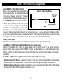
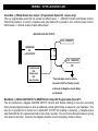
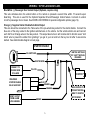
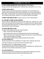
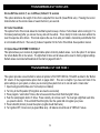
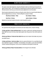
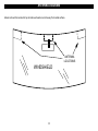
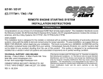
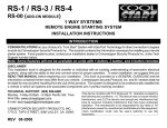
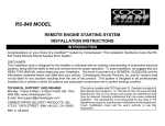
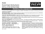
SP-400
Alarm / Remote Start Combo System
INSTALLATION HANDBOOK:
INTRODUCTION
Congratulations on your choice of a Crimestopper combination alarm & remote engine starter with Data Port
Technology.
This installation book is designed for the installer or individual with an existing understanding of
automotive electrical systems, along with the ability to test and connect wires for proper operation. To ease
installation, we suggest that you READ THIS MANUAL before beginning your installation. This book is
provided as a GENERAL GUIDELINE and the information contained herein may differ from your vehicle.
DISCLAIMER:
Crimestopper Security Products, Inc. and its vendors shall not be liable for any accident resulting from the
use of this product. This system is designed to be professionally installed into a vehicle in which all
systems and associated components are in perfect working condition.
TECHNICAL SUPPORT (800)-998-6880
Monday - Friday 8:00am - 4:30pm Pacific Time
Website: www.crimestopper.com
CRIMESTOPPER SECURITY PRODUCTS, INC.
1770 S. TAPO STREET
SIMI VALLEY, CA. 93063
REV. 11.2008
This device complies with FCC Rules part 15. Operation is
subject to the following two conditions: 1) This device may not
cause interference, and (2) this device must accept any
interference that may be received, including interference that
may cause undesired operation. The manufacturer is not
responsible for any radio or TV interference caused by
unauthorized modification to this equipment. Such
modification could void the user's authority to operate the
equipment.
TABLE OF CONTENTS
Cautions & Warnings…….…………………………..…..………………………………………………………………………3
Component Mounting………….……………………..……………………………………………….…………………..……..3
Wiring Information ………….…………………………....……………...……………………………………………..……4-11
Power Door Lock Wiring……………………….....….………………...….………..…….……..…………...……………12-14
Tachless, Tach Reference, Tach Finder, Timed Crank Modes………..……………………………………………....15-17
Diesel Glow Plug Delay………………………………………………………………………………………………...………18
Programmable Options, Options Reset……….………………………………………………….………….………...…18-24
Remote Transmitter Programming……………………………………….……………..…………………...…...…...……...25
Remote Start and Alarm Trigger Diagnostics…….…….………………………………………...…………………...…….26
Jumper Pin Diagram..…………………………………………………………………………………………………...……..27
Antenna Diagram ……………………………………………………………………………………………………………....28
High Current Connector Plug………………………………………………………………………………………………….29
System Wiring Diagram………………………………………………………………………………………………………..30
DATA Port Diagram..……………………….……………………………………………………………………..……………31
PR
PRE-INSTALLATION CONSIDERATIONS
BEFORE BEGINNING, check all vehicle manufacturer cautions and warnings regarding electrical service (AIR BAGS, ABS
BRAKES, ENGINE / BODY COMPUTER AND BATTERY).
PLAN OUT YOUR INSTALLATION. You should pre-determine the location of the Control Module (Brain), Valet button,
LED, and Siren locations. This will save time and ease the installation process.
USE VOLT/OHM METER to test and locate all connections.
vehicle’s computer system or cause an airbag to deploy.
Test Lights or Lighted Probes could possibly damage a
ADDITIONAL PARTS, that are not included with this unit, may be needed for your particular vehicle. These items may
include extra relays, Door Lock Interface Modules, or Transponder Override modules.
2
CAUTIONS & WARNINGS
DAMAGE RESULTING FROM IMPROPER INSTALLATION IS NOT COVERED UNDER WARRANTY!!
DO NOT remote start your vehicle in a closed garage. Make sure that the garage door is open or there is adequate
ventilation. Failure to observe this rule could result in injury or death from poisonous Carbon Monoxide fumes.
DO NOT ROUTE ANY WIRING THAT MAY BECOME ENTANGLED with the brake/gas pedals, steering column, or
any other moving parts in the vehicle.
REMOVE MAIN SYSTEM FUSE(S) before jump-starting the vehicle or charging the battery at high boost. DAMAGE
MAY OCCUR TO SYSTEM IF PROPER PRECAUTIONS ARE NOT OBSERVED.
DO NOT exceed the rated output current of any circuit on the Remote start module. Failure to observe this warning
will result in damage to the unit. Output currents are listed where applicable throughout this manual.
DO NOT extend the Remote start ignition harness length. Mount the module so that main harness reaches all
ignition switch wiring. Extending these wires could result in poor performance.
COMPONENT MOUNTING
CONTROL MODULE: The alarm control module should be mounted in a concealed location. DO NOT mount the
control unit in the engine compartment. Fasten the module to a bracket or wire harness using the cable ties
provided.
ANTENNA MODULE: For optimum range and performance, the antenna/receiver module should be located high up
on the front windshield glass. For example: behind the rearview mirror. Note: Window tints or Films may decrease
the range of the system. The mounting surface for the antenna should be clean and dry.
SIREN MOUNTING: Mount the siren under the hood to fender-well or other body surface with the open end facing
downward. Run the red siren wire through the firewall using a rubber grommet. Ground the black wire to the body
metal near the siren.
LED: Mount the Blue LED (Red for CS-2011) in a visible location on the dashboard or console.
SHOCK SENSOR: Mount the included shock sensor with wire ties to an under dash wire harness or fasten with
screws to firewall or side paneling.
OVERRIDE/PROGRAM/VALET BUTTON: Mount the Override/Program push-button in a hidden but accessible
location. This button is required for emergency disarm, programming, and valet mode.
3
WIRING: 9-PIN Connector (22 gauge wires)
Green: MODE A: (-) Start Activation Input
This wire allows an outside source or accessory to
activate a Remote Start. A 1-second Ground pulse
on this wire will trigger a remote start. This wire
can be used with an RS-400 temperature module.
Optional Turbo Timer Wiring
Momentary
Switch
GREEN
Green: MODE B (-) Optional Turbo Timer Input
(3 Modes, Option #30) This wire allows the system
(Not included)
to keep a vehicle running for 1-5 minutes
[selectively] after removing the key. This mode
requires the use of a momentary switch that is not included with the kit. Connect a 2-pole momentary switch with
one side to chassis Ground and the other side to the Green input wire. If you own a turbo or turbo diesel vehicle,
you can now allow the system to keep your engine running for 1-5 minutes after exiting/locking your vehicle to cooldown without the need for an external “Turbo Timer”. See operator’s manual for more information.
Brown: (+) Siren Output
Connect brown wire to siren red wire. Connect black wire of siren to chassis ground (body metal).
Brown/White: (-) 500mA Horn Honk Output (Optional, may require a relay)
Connect to the Negative Horn Trigger wire usually located near the steering column. If the vehicle horn circuit
requires +12V, a relay is required. RELAY WIRING: Connect the Brown/White wire to terminal 85, connect relay
terminals 86 and 87 to +12V constant power. Connect terminal 30 of the relay to the +12V positive device/circuit to
be activated.
Black/White: (-) 500mA Dome Light Illumination Output (Optional, Requires relay)
Negative Dome Light System: Connects to terminal 85 of a relay. Connect terminal 86 to +12V Constant.
Connect terminal 87 to Chassis Ground. Connect Terminal 30 to the Negative dome light activation circuit.
Positive Dome Light System: Connects to terminal 85 of a relay. Connect terminals 86 & 87 to +12V Constant.
Connect terminal 30 to the Positive dome light activation circuit.
4
WIRING: 9-PIN Connector Cont.
Green/Red: (-) 500mA Remote Aux. Output 1 (Programmable Option #10, requires relay)
This is a programmable output that can operate two different ways: 1 - (DEFAULT) Disarm with Remote Auxiliary
Output that provides a ½ second (-) Negative pulse when Button #3 is pressed to open a Factory power trunk or
hatch release. 2 - Remote Auxiliary Output without disarm
NEGATIVE AUXILARY OUTPUT
+12V CONSTANT
GREEN/RED
OR
(-) AUX OUTPUT
85
86
30
87
+12V CONSTANT
OR *
Trunk Soleniod
-ORDome Light
-ORAux Function
* Test activation circuit in vehicle.
Connect to+12V for Positive circuits
or Ground for Negative circuits. Relay
not included.
Blue/Black: (-) 500mA IGNITION OUT or REMOTE AUX. Output #2 (Programmable Option #17)
This wire functions as a Negative IGNITION OUTPUT (Ground while Remote Starting) for use when connecting
factory Security Bypass modules or when an additional external Ignition Relay is required for your installation. This
wire can be programmed to function as an AUXILIARY OUTPUT #2 providing a momentary (-) Negative output
when Button #6 then #1 is pressed and held for more than 2 seconds. The Aux Channel #2 output stays on as long
a the button is held down. Connect to the Negative activation circuit of an auxiliary module or device.
5
WIRING: 9-PIN Connector Cont.
Blue/White: (-) Passenger Door Unlock Output (Optional, requires relay)
This wire activates when the unlock button on the remote is pressed a second time within 15 seconds upon
disarming. This wire is used for the Optional Separate Driver’s/Passenger Unlock feature. Connects to unlock
circuit for passenger door or doors. See DOOR LOCK WIRING for special configuration options (page 14).
Orange: (-) Negative Starter Disable/Anti-Grind Output
This wire should be connected to the Yellow wire of the pre-wired relay socket for the starter disable. Connect the
blue wire of the relay socket to the Ignition switched wire on the vehicle. Cut the vehicle starter wire and connect
each half to an Orange wire on the relay socket. This output also turns on with remote start to function as an “Anti
Grind” wire to prevent the starter from grinding if you get in your car and turn the key too far after it was remote
started. See starter disable diagram on next page.
STARTER DISABLE:
IGNITION SWITCHED
"ON" & HOT THROUGH
CRANKING
IGN. SWITCHED
STARTER WIRE
CONNECT TO
ORANGE WIRE
OF ALARM
PRE-WIRED
STARTER DISABLE
RELAY & SOCKET
START OUTPUT
FROM ALARM
6-PIN HARNESS
CUT
YELLOW
STARTER
BLUE
ORANGE
ORANGE
BROWN
6
MAKE CERTAIN TO
CONNECT BROWN
WIRE TO STARTER
MOTOR SIDE!!!
WIRING: 9-PIN Connector Cont.
Orange/Black: (-) OEM Disarm Output
This wire provides a Ground pulse to disarm the vehicles Factory Anti-Theft System prior to a Remote Start.
Connect this wire to the vehicles' anti-theft disarm wire. This wire is sometimes found coming off the Driver's door
key switch or at the Factory Anti-theft control module.
WIRING: 3-PIN Connector (18 gauge wires)
White/Red: Tachometer Input
When installing this system in TACH REFERENCE mode, this wire must be connected to a valid source of AC
voltage. This wire allows the unit to sense the engine running. See Tach Section on Page 15-17 for more
information.
Black: Chassis Ground
Connect to body metal of the vehicle using a sheet metal screw and a star washer to ensure a good ground. Keep
the Ground wire short. Scrape away paint or debris from ground location.
WHITE: 10 Amps +12 Volts or (-) 500mA NEGATIVE PARKING LIGHT OUTPUT:
Connect to vehicle parking light circuit at the back of light switch or if this is not possible, connect directly to one of
the parking lights at the front of the vehicle. If your vehicle has a multiplex lighting system that requires a (-)
Negative parking light output, then move the jumper from (+) to (-). See Jumper Pin Diagram (Pg. 27). Some
European vehicles require separate left and right circuits. Use a dual relay or diodes to isolate the output.
NOTES: (1) Default parking light output is +12 volts. (2) Use an external relay for vehicles that draw excess
current from extra running lights, light bars, or trailers. Parking light output is limited to +10 or (-)0.5 AMPS.
WIRING: 6-PIN High Current Connector (14 gauge wires)
\
PIN 1: GRAY:
PIN 2: BROWN:
PIN 3: RED:
PIN 4: RED:
PIN 5: PINK:
PIN 6: PINK/WHITE:
ACCESSORY (HEAT/AC) (30A)
STARTER OUTPUT (30A Max.)
+12V POWER INPUT (BATTERY) FUSED (30A)
+12V POWER INPUT (BATTERY) FUSED (30A)
IGNITION 1 (30A Max.)
START 2, IGN 2, ACC 2 OUTPUT (30 Max.)
7
NOTE! Use External Relays
for High Current Ignition
and/or Accessory circuits
greater than 30A. Failure to
do so could result in damage
to the unit that is not covered
under warranty.
WIRING: 5-PIN Connector (22 gauge wires)
Violet: (+) Door Pin Switch Input
Same as the GREEN wire below except this wire is used for vehicles that show a positive voltage (+12 volts) when
the door is open and a ground when doors are closed as in many Ford, Lincoln, and Mercury vehicles.
Green: (-) Door Pin Switch Input
Identify the wire that reads ground when any door is open and 12 volts when all doors are closed. Some vehicles
may have isolated door triggers. In this case you may need to run additional wires from other doors or go directly to
the wire that triggers the vehicle’s interior dome light. Sometimes newer vehicles contain a separate body control
module (BCM) where the door trigger circuit can be located. Most vehicles will NOT require the use of BOTH Green
and Violet door trigger wires.
Blue: (-) Hood/Trunk Pin Switch Input
Input trigger for a grounding hood or trunk pin switch. Connect to existing hood and trunk pin switches that read
ground when open. If no existing switches are available, install new pin switches if desired. Note: DO NOT mount
new pin switches in water pathways.
Pink: (+12V) +/- Diesel Glow Plug Input or Passive Carjack Input (Programmable Input Wire)
+/- Trigger: See diagram (Pg. 27) for Jumper Pin Configuration.
+/- Glow Plug Input (Diesel Vehicles Only)
Connect Pink wire to indicator circuit that shows a (- or +) Signal while the “WAIT TO START LAMP” is on.
When this wire is used, the system will wait until light turns off before attempting a remote start.
Passive Carjack Trigger
When using Carjack protection, connect this Pink wire to a (+ or -) toggle switch, or +12V ignition source
depending on your level of Carjack protection. When +12V is applied to this wire with the IGN on, then Carjack
is armed. If a door is opened then closed with ignition on, the Carjack countdown will begin. See Diagram
Below for wiring configurations. DO NOT connect the Pink Carjack wire to Ignition unless there is extreme
danger of a Carjack. When using the Ignition, Carjack is armed all the time and must be reset each time a
door is opened and closed.
8
WIRING: 5-PIN Connector Cont.
OPTIONAL CAR JACK WIRING:
HIDDEN BUTTON or
TOGGLE SWITCH
(Not Included)
PINK
IGN SW
+ IGN
+
12 V
PINK
FULL-TIME CARJACK
CONTROLLED W/SWITCH
White: (+12V) Brake Reset
Connect the White wire to the side of brake pedal switch that shows +12 volts ONLY when pedal is depressed. This
will turn off the remote start if someone attempts to drive the car without the keys or if the Ignition key is not turned
on all the way.
WIRING: 2-PIN LED / 2-PIN Program-Valet Button (26 gauge wires)
Mount LED in a visible location on the Dash or Console. Connect the small 2-pin plug from the LED to the control
module. Note: Connectors are designed so that they will only plug into their appropriate slots.
Mount the Valet/Program/Override button in a suitable location. Connect the 2-pin plug from the Switch to the
control module. Note: Connectors are designed so that they will only plug into their appropriate slots.
VALET / PROGRAM SWITCH
STATUS LED
9
WIRING: 4-PIN Shock Sensor (26 Gauge wires)
Sensor Adjustment
Adjust the main shock sensor with the small White dial. Clockwise will increase sensitivity and counter-clockwise
will decrease sensitivity. Adjust Pre-Warning level with small Black dial.
RED LED (Trigger)
GREEN LED (Pre-Warn)
+
Adjustments
(-) TRIGGER
(-) PRE-WARN
+
WHITE
BLUE
GROUND
BLACK
12 VOLTS
RED
SHOCK SENSOR: The sensor supplied with this system
does not require any additional wiring. Simply mount the
sensor in a suitable location, plug it in, and adjust for
sensitivity.
10
WIRE: 4 PIN OUTPUT CONNECTOR (22 gauge wires)
YELLOW/BLACK: (-) OEM REARM OUTPUT
This wire provides a ground pulse to rearm the vehicles' FACTORY anti-theft system after a timed-out or aborted
remote start. Connect this wire to the vehicles' anti-theft rearm wire or to the door pin circuit depending on your
requirements. This wire may be needed to pulse the door pin circuit on vehicles with retained accessory power.
BLUE/ORANGE: (-) STARTER #3
This wire provides a ground output for vehicle that requires a third starter wire to remote start.
BLUE/ORANGE
CONNECT TO IGN
85
86
30
87
+
BATTERY
STARTER
VIOLET/WHITE: (-) AUX. 3
The Violet/White wire for a negative output for a Momentary, Pulse, Timed or Latched output, depending on option
used. Option #26 and 27 controls these functions.
GREEN/WHITE: (-) AUX. 4
The Green/White wire for a negative output for a Momentary, Pulse, Timed or Latched output, depending on option
used. Option #28 and 29 controls these functions.
11
POWER DOOR LOCKS: (22 gauge wires)
PIN 1: BLUE: (-) Negative pulse for UNLOCK
PIN 2: RED: 12V When using external relays (TERM 86)
PIN 3: GREEN: (-) Negative pulse for LOCK
Crimestopper Door Lock Accessories:
CS-6600DLM: Dual-relay plug-in module for Reverse
Polarity, Positive, or Aftermarket Motors.
CS-6500DLI: Plug-in pulse inverter that converts the
Negative outputs of the system to Positive type for Positive
Door Lock systems.
CS-610S1: Aftermarket door lock actuator (motor).
DETERMINING DOOR LOCK TYPE: We recommend
determining the type of locking system the vehicle has
before connecting any wires. Incorrect connection may
result in damage to the alarm and/or vehicle locking system.
Door lock information is provided as a guide. Your vehicle may be different.
Negative Trigger (-): Many Imports; Late model Ford & General Motors
Negative trigger door lock systems send a Negative (Ground) pulse to existing factory relays to lock and unlock the
vehicle doors.
Positive Trigger (+): Many General Motors; Chrysler / Dodge / Plymouth
Positive trigger door lock systems send a Positive (12V) pulse to existing factory relays to lock and unlock the
vehicle doors.
Reverse Polarity: Many Ford/Lincoln/Mercury/Dodge/Chrysler/Plymouth and early 90’s GM Trucks
Reverse Polarity systems use no relays, but instead the door lock/unlock motors are controlled directly from the lock
and unlock switches in the door. The lock and unlock wires rest at Negative Ground when not in use. When the
lock or unlock button is pressed, one of the circuits is “Lifted” and replaced with +12V causing a lock or unlock to
occur.
Single Wire (Dual Voltage): Late model Chrysler/Dodge/Plymouth Vehicles, some 2000-UP GM
Dual Voltage systems have lock/unlock switches that send varying levels of Positive voltage OR Negative ground
current to the SAME wire for both lock and unlock. When the vehicle’s Body Computer Module (BCM) or door lock
module senses different voltages on this wire, the system will either lock or unlock. Single wire door lock systems
require relays and resistors.
Databus Systems 2003-UP GM Trucks & SUV’s, ‘96-04 Jeep Grand Cherokee
Databus systems send low current “Data messages” to the door lock controllers on a network in order to lock and
unlock the vehicle. To install aftermarket systems in these vehicles, an interface module is required that converts
the regular lock/unlock pulses into “Data messages” to allow locking & unlocking. Interface modules are sold
separately.
12
DOOR LOCK WIRING
NEGATIVE TRIGGER DOORLOCK WIRING
POSITIVE TRIGGER DOORLOCK WIRING
GREEN
GREEN
RED
BLUE
RED
FUSED
+12V
+
BLUE
85
86
87
87A 30
FACTORY
POWER
LOCKING
RELAYS
L
UL
87
87A 30
FACTORY
POWER
LOCKING
UL
RELAYS
AFTERMARKET MOTOR/DOOR LOCK WIRING
GREEN
GREEN
FUSED
+12V
+
RED
BLUE
85
86
87
87A 30
85
85
86
86
87
87A 30
87
87A 30
CUT
L
FUSED
+12V
+
RED
BLUE
MASTER
SWITCH
UL
86
L
REVERSE POLARITY DOOR LOCK WIRING
+
85
CUT
13
85
86
87
87A 30
SEPARATE DRIVER’S DOOR UNLOCK WIRING
NEGATIVE TRIGGER DOOR LOCKS
BLUE/WHITE
GREEN
RED
BLUE
DRIVER'S
DOOR MOTOR
85
86
L
87
30 87A
L
UL
+
UL
FACTORY LOCK
RELAYS
+12V
FUSED
CUT
UNLOCK WIRE
WIRING FOR REVERSE POLARITY DOOR LOCKS
BLUE/WHITE
GREEN
RED
FUSED
+12V
+
BLUE
MASTER
SWITCH
85
85
86
86
87
87A 30
87
30 87A
+
L
86
87
87A 30
CUT
UL
CUT
85
CUT
LOCK WIRE
UNLOCK WIRE
14
TACHLESS MODE
Your system includes a Tach-less mode that actively monitors and compares the vehicle’s resting voltage versus its
running voltage each time a remote start is performed; [instead of the conventional tach-pulse method]. Smart
Tachless mode adjusts automatically to maintain optimum efficiency over the life of the installation.
IMPORTANT NOTES:
(1) SETUP may be required for the Tachless Mode. If your vehicle has NOT been at rest for a period of time (Hot
engine), then you must drain the surface charge from the battery. Unplug main power harness from system, turn
HEADLIGHTS ON for 4 minutes to drain off excess surface charge on vehicle’s battery then reconnect.
(2) On the rare occasion that Tachless mode does not operate satisfactorily, change the voltage reference level as
described below, or use a different mode such as “Tach Reference” mode, or “Timed Crank” mode.
TACHLESS ADJUSTMENT:
In the event Tachless over-cranks or under-cranks your starter, the settings can be changed. The purpose of
adjusting the “Smart Tachless” Mode is to raise or lower the voltage reference threshold from the 93% default point.
Raising or lowering this 93% point should increase or decrease your cranking time respectively. You can adjust the
range from 79% to 100% in one percent increments. Factory default setting [starting point] is in the middle at 93%
which should work for most vehicles. If you feel you need to fine tune the Tachless mode, then follow the steps
below to adjust its reference level.
1.
2.
3.
4.
Open hood (or ground the Blue hood pin wire if no hood pin is installed)
Turn the key to the ON position (do not start vehicle).
Press program button 5 times, after a few seconds the unit will flash the lights 5 times.
Carefully press the program button 24 times to get to option # 24. You must get a light flash after each press. If
the lights didn’t flash, then the unit did not register your button press. Only count the light flash.
5. Press the Lock Button #1 on the remote to decrease by 1% (lights will flash 1X for each press); Press the Unlock
Button #2 to increase by 1% (lights will flash 2X for each press); Press the Trunk Button #3 to reset to 93% (lights
will flash 3X). The unit will stop providing light flashes when you reach the bottom (79%) or the top (100%) of the
adjustment range. If you lost track, then just press Button #3 to reset back to 93% and begin again.
6. Turn Ignition OFF, Close hood (or un-ground the Blue wire) and check operation.
15
TACH MODE & TACH FINDER FEATURE
Tach Reference Mode provides reliable remote starting performance though engine speed sensing. When using
Tach Reference Mode, the WHITE/RED wire is used for Tach signal [Engine RPM] input. Most modern engines
include various points where the Engine Speed [Tach] or A/C signal may be obtained. Tach Signal examples:
Negative (-) side of ignition coil, at the Distributor or Ignition Control Module, Coil Pack, Engine Computer, or
Crankshaft Sensor. Sometimes Fuel injection solenoids and Alternator stator pins can be used. These Tach Signal
locations mentioned are provided as a guide, your vehicle may differ. Some locations will NOT be a good location
for Tach source due to RF noise or Computer Data. Use the TACH FINDER feature if needed.
TACH FINDER FEATURE:
The Tach Finder mode can assist you in locating or verifying a Tach source for your installation. Follow the Tach
Finder steps below to locate signal. The unit will begin to flash the parking lights if you have the White/Red wire
connected to a valid tach source. If lights do not flash, then try another wire until you locate a tach signal that will
cause the Parking lights to flash. NOTE: On vehicles equipped with daytime running lights, it may be difficult to see
any flashing parking lights. In this case your only notification will be the slight “ticking” sound coming out of the
module from the on-board flashing light relay.
TACH FINDER:
1. Open hood (Ground the Blue hood pin wire if no hood pin is installed)
2. Start Engine with the key. (Pink ignition wire must be connected)
3. Press the Program button for 2 seconds
4. Lights will begin flashing if the White/Red wire is connected to a valid tach
5. Once Tach is located then turn off engine and close hood to abort.
6. See Tach Reference programming below.
TACH PROGRAMMING:
1. Open hood (Ground Blue hood pin wire if no hood pin is installed).
2. Connect WHITE/RED wire to a valid Tach source.
3. Start engine with the key (Pink ignition wire must be connected).
4. Press program button 5 times, then wait for 5 light flashes.
5. Wait at least one second then push program button again (1) time, you should get a light flash with the button
press. This unit is now at option #1 for Tach Learning.
6. Press the #1 Lock Button on remote transmitter to program Tach. NOTE: Pressing the Brake Pedal also
programs Tach. One Light Flash = Tach Mode. Two Light Flashes = Tachless Mode.
7. If lights do not flash for confirmation, then try another tach source or try the tach finder feature above.
16
TIMED CRANK MODE
As an alternative to Tach or Tachless mode, “Timed Crank” provides an additional method of starting the vehicle
without locating an exact tach wire. It uses a timed cranking output combined with the use of the Red/White tach
wire as an engine ON/OFF monitor. The Red/White Tach wire MUST STILL be used with this mode. THIS
FEATURE MUST BE PROGRAMMED BEFORE USE! THERE ARE 2 LEVELS of programming required: First, set
the system for “Timed Crank” operation, and secondly you may need to adjust the amount of cranking time. There
are 4 different crank times available for use. SEE OPTION PROGRAMMING CHART FOR SETTINGS.
HOW TO USE THIS FEATURE:
1. Go to the “Programmable Options” section, and set Option #16 to “Pre-Set". (It is normally set to “Tach Monitor”)
2. With “Pre-Set” Cranking time turned ON, you will STILL have to connect the Red/White Tach wire to a tach
source on the engine. The Red/White Tach wire becomes a simple “Engine Monitor”. Although the unit will not
be using the Red/White wire to start the motor, it will be using this wire to determine whether the motor is running
or not. This is a mandatory connection. A “crude” or “less exact” tach source can be used only when in “Time
Crank” mode.
3. Using the vehicle key, start the engine to get a “feel” of how long the cranking time is. Once the “Timed Crank”
mode is turned on, the default cranking time is set to a Default of 0.50 seconds. We recommend beginning with
this setting. Try a remote start and see if the cranking is appropriate for your vehicle
4. If 0.50 seconds is not an appropriate starter cranking time, then go to Programming Option #21 and change the
crank time setting to a longer value. The values are as follows: 0.5, 0.75. 1.0, and 1.5 seconds.
WARNING: This method of starting the vehicle is not as reliable as using regular “Tach” or “Ultra-Smart”
Tachless modes. This method should be used only in the event that a tach wire cannot be located using the
normal tach programming and tach finder. When using this method, there may be certain operating
anomalies requiring seasonal adjustments. These are, but not limited to:
• Starter may under-crank in extreme cold weather. Vehicle may not start on 1st attempt and may require a
2nd try, 3rd try, or may not start at all if unsuccessful after 3 attempts.
• In warm weather when your vehicle may start very quickly, “Timed Crank” mode may tend to over-crank
the starter.
• The only way to possibly correct the above issues is to go to the Option #21 and adjust the cranking
time. When in “Timed Crank” mode, the cranking time can only be adjusted manually through option
#21. When using Ultra-Smart Tachless or Regular Tach modes, cranking time is adjusted automatically.
17
DIESEL GLOW PLUG DELAY
This feature provides a solution for diesel vehicles without having to connect to the Glow Plug-“Wait to Start Circuit”
input. This may be due to a variety of reasons for example: If your vehicle does not have a viable “Wait to Start
Circuit” or you cannot locate and identify the circuit. You can choose from a selection of “pre-cranking” delay times.
Once this mode is activated, the system will NO LONGER monitor the PINK glow plug input wire and will use a
delay setting chosen by the installer in the option chart.
NOTES: This feature is OFF by default and must be programmed before use. Once this feature is turned ON, the
Pink Glow plug input wire is not used. The Remote start unit will always wait the programmed time before cranking
EVEN IF the glow plugs warm up first. There are 3 different Delay times available for use: 10, 20, or 30 seconds.
SEE PROGRAMMING OPTION CHART, next section.
HOW TO USE THIS FEATURE:
1. See the “Programmable Options” next section and change Option #22 from "Monitor Glow Plug Light" to one of
the delayed time values. (Default setting is to always monitor the PINK Glow Plug input wire.)
2. Once this option has changed the system will wait for the selected time before cranking the engine.
PROGRAMMABLE OPTIONS
You can program multiple options in one session if you start with the lowest option and continue on to higher options
[if needed] without repeating steps #1-3 below. For example, you can follow the programming steps to change
Option #2 to “OFF” by pressing the lock button on the remote, then you can continue pressing the program button
additional times to get to a high number option and change the setting without having to repeat Steps 1-5. You can
only go from low to higher option numbers in one session.
To Engage Option Programming:
1. Open Hood (ground blue hood pin wire if no hood pin switch is installed)
2. Turn Key to the ON position
3. Press program / valet button 5 times, after a few seconds the unit will flash the lights 5 times.
4. Push the valet/program button [again] the number of times that corresponds to the option number desired (1 thru
30). You must get a light flash after each button press. See chart on next page for option list.
5. When you reach the desired programming level, Press button #1, #2 #3 or #4 to change the option.
6. Turn Ignition OFF, Close hood (or unground blue hood pin wire) and check for changed features. Change each
option individually repeating #1-5.
18
OPTION PROGRAMMING TABLE
Option
#
Option Description
TX Button #1
TX Button #2
1
Engine Monitoring
Learn Tach
*Tachless*
2
Auto lock with Ignition
OFF
*ON*
3
Passive Arming
With Ignition or Last Door
Ignition and last door
ON
*OFF*
4
Active Re-Arm
ON
*OFF*
5
Passive Locks
ON
*OFF*
6
Parking Lights on w/Disarm
OFF
*ON*
7
Data Port Protocol
OFA Series or SL Series
OFA Series
*SL Series*
8
Remote Start & Auxiliary Output
Button Press Selection
Double Button Press
*½ Second Press*
9
Siren Chirps on Remote Start
OFF
*ON*
10
Disarm on Trunk pop
OFF
*ON*
11
Open Door Warning
5 Sec.
*60 Sec.*
12
Door Lock Pulse Time
3 Sec.
*0.5 Sec.*
13
Double Unlock Pulse
2 Pulses
*1 Pulse*
14
Lock After Remote
Start/Abort
OFF
*ON*
15
Manual Transmission Mode
ON
*OFF*
16
Timed Crank or Tach Monitor
Pre-Set
*Tach Monitor*
17
Blue/Black Wire Function
AUX #2
*(-) Run / Ignition*
18
Siren Chirps with Arm/Disarm
OFF
*ON*
19
“Wake Up" pulse on Unlock
(1-sec. +12V to IGN)
ON
*OFF*
19
TX Button #3
TX Button #4
Ignition only
Last Door only
Press and Hold
OPTION PROGRAMMING TABLE
20
PINK Wire function
Passive Carjack
*Glow Plug*
21
Starter Cranking Time (Option
#16 is set to Timed Crank)
0.75 Sec.
*0.5 Sec.*
1.0 Sec.
1.5 Sec.
22
Diesel Glow Plug Delay
10 Seconds
*Monitor Glow
Plug
20 Seconds
30 Seconds
12 Minutes
*24 Minutes*
36 Minutes
48 Minutes
-1%
1%
*Set to 93% for
default*
No Warn-A-Way
*All Functions*
*Momentary*
Timed
23
24
Remote Start Engine Run
Time
Smart Tachless Voltage
Adjustment 79-100%
25
Horn Pulse
26
Aux # 3
Pulse With Trigger
(No Chirps)
Steady Momentary
27
Aux # 3 Time : 1 to 255 sec.
-1 Second
+1 Second
*Default 12 Sec.*
28
Aux # 4
Steady Momentary
*Momentary*
Timed
29
Aux # 4 Time : 1 to 255 sec.
Turbo Timer Mode
1 to 5 Minutes
-1 Second
+1 Second
*Default 12 Sec.*
Brake Pedal Set Mode
*Always Set Mode*
Idle Down Mode
30
31
All Functions
Short Chirp
Latch On/Off
Latch On/Off
*Reset All
Options*
Reset Options to default (*)
PROGRAMMABLE OPTION DESCRIPTIONS:
1. ENGINE MONITORING:
This option sets how the unit monitors your engine. You can program either for Tach mode in which the unit uses a
Tach signal (RPM) or for “Ultra-Smart” Tachless mode that monitors voltage level. See pages 15-17 for more
information and additional steps for actual Tach learning and Tach finder modes.
2. AUTOLOCK/UNLOCK W/IGNITION:
Controls whether the doors will automatically lock when the ignition is turned on and unlock when the ignition is
turned off. Doors will not lock if they are open to prevent locking the keys in.
20
PROGRAMMABLE OPTIONS Cont.
3. PASSIVE ARMING Passive Arming With Ignition or Last Door:
With this option ON, the unit will arm itself 30 Seconds after the ignition is turned off and/or the last door has been
closed. Lights will flash twice when last door is closed indicating passive countdown. If a door is reopened, the
system will wait and begin countdown again when closed. The LED will flash rapidly during 30 second count down.
4. ACTIVE RE-ARM: Active Re-arming allows the system to re-arm itself 30 seconds after disarmed with the
transmitter if a door has not been opened. The status LED flashes rapidly during 30 second re-arm countdown. This
is handy if the vehicle is accidentally disarmed without your knowledge.
5. PASSIVE LOCKS:
This option controls whether the doors will lock when Passive Arming occurs. Note: This may increase the risk of
locking keys in the vehicle.
6. PARKING LIGHTS ON WITH DISARM:
Keeps parking lights on when system is disarmed to assist in locating and providing illumination near your vehicle
when approaching at night for safety.
7. Data Port Protocol:
This option controls the Data Port Protocol for OFA Series modules or SL Series modules. The default is set for SL
Series Protocol. This option has no effect on conventional wiring of Bypass modules. Both OFA series and SL series
are now 2-Way Protocol.
8. Double Button Press for Remote start and Trunk release:
This option will allow you to change whether the Remote starter and Trunk release activate by a single ½ second
press, a double button ½ second press or a double press.
9. SIREN CHIRPS WITH REMOTE START ACTIVATION:
This option controls whether the system gives 3 short siren chirps when engaging a remote start.
10. DISARM WITH TRUNK POP (AUX. OUTPUT 1):
Controls whether the system will or will not DISARM when the trunk pop or AUX. feature is used. When the feature
is turned on the unit will DISARM when opening trunk or using an auxiliary device controlled by the Green/Red wire.
11. 5/60 Sec. OPEN DOOR WARNING:
This setting changes the delay time in which the alarm system begins to monitor the Door circuit. This option can
prevent the alarm from giving warning chirps on vehicles with a delayed dome light.
21
PROGRAMMABLE OPTIONS Cont.
12. DOOR LOCK/UNLOCK PULSE TIME:
This option controls the amount of time (0.5 sec. or 3 sec.) for the lock/unlock pulse. The standard pulse time for
most vehicles is 0.5 Sec. The 3 sec. setting may be required for Mid 1980’s through Mid 1990’s European Vehicles
that require a long lock and unlock pulse to operate Vacuum door lock systems.
13. DOUBLE UNLOCK PULSE:
With this option ON, the unit will send 2 unlock pulses when the system is disarmed. This feature may be required
for interfacing a Factory alarm or keyless entry system.
14. LOCK DURING/AFTER REMOTE START:
This option controls whether the unit will automatically lock during and after a remote Start abort or time-out.
15. Manual Transmission Mode: Authorized Crimestopper Dealers Only. Call Tech Support for Instructions.
16. TIMED CRANK or TACH MONITOR MODE:
This option controls whether the system uses a tach wire to control the starter or uses a pre-set cranking time.
17. BLUE/BLACK WIRE PROGRAMMING: (NEG.) IGNITION OUTPUT or AUX #2 OUTPUT:
This option controls the function of the Blue/Black wire as either a Ground with Remote Start or a 2nd Aux. Channel
18. SIREN CHIRPS WITH ARM/DISARM:
With this feature, siren chirps with Arm/Disarm can be programmed either ON or OFF when using the regular
Lock/Unlock Buttons. When chirps are OFF, the Flashing parking lights will be the only Arm/Disarm confirmation.
19. +12V “WAKE UP” PULSE:
This option allows the unit to provide a 1-second pulse on the Pink main ignition output when unlocking. The
Ignition pulse serves to “Wake up” vehicle control modules or body computers that “time out” or go into power
saving mode. This is required on many late model Ford vehicles with a “Slam” lock system in order to actually
unlock the vehicle after it has been at rest for a short period of time.
20. PINK WIRE PROGRAMMING: PASSIVE CAR JACK TRIGGER or GLOW PLUG INPUT:
This option controls whether the system’s PINK input wire functions as a Glow Plug input wire for Diesel Engines or
a +12V input for tripping a Carjack countdown. For Glow plug, this wire should be connected to the wait to start light
circuit. For Carjack this wire can be connected to a hidden push button, or a +12V Ignition circuit for Passive Car
Jack operation (see operations manual).
22
PROGRAMMABLE OPTIONS Cont.
21. PRE-SET STARTER CRANKING TIME: (Requires Option #16 in “Pre-Set” Setting)
This option controls the starter cranking time when in “Timed Crank” Mode. Choices are 0.5, 0.75, 1.0, or 1.5 sec.
22. DIESEL GLOW PLUG DELAY
This option controls the system’s Diesel vehicle interface. Using this option you can control whether the unit
monitors the vehicle’s glow plug circuit using the Pink input wire (Default), or you may select a specific delay time
Before cranking. This option is helpful if you are unable to locate a glow plug signal. Just select a delay time and
do not connect the Pink Glow Plug wire. Selections: 10, 20, 30 seconds, or Monitor Pink Wire (Default).
23. REMOTE START ENGINE RUN TIME: Set engine run time for 12, 24, 36 or 48 minutes as desired.
24. ULTRA-SMART TACHLESS VOLTAGE ADJUSTMENT:
This option controls the voltage reference point when using smart Tachless mode. Pressing the Lock or Unlock
buttons on the remote raises or lowers the reference level in 1% increments from 79%-%100. Button #3 resets the
unit to the factory default reference point of 93%. The default 93% setting works for most vehicles. See page 15 for
additional Ultra-Smart Tachless mode information.
25. FACTORY HORN CHIRPS / PULSES:
This option controls the system’s horn honk output. There are 3 selections:
4 Button 1 (Lock): Pulse horn when alarm is triggered.
4 Button 2 (Unlock): Pulse horn when alarm is triggered and Honk when Alarm is Armed and Disarmed.
4 Button 3 (Trunk Pop): Pulse horn when alarm is Triggered, Honk when Alarm is Armed and Disarmed and
Pulse when Shock pre-warning is set off. (default)
4 Button 4 (Start): Short Arm/Disarm Chips. Reduces the pulse from 0.04 to 0.02 seconds.
26. Aux #3: (Violet/White wire)
This option controls the function of the Violet/White wire for a negative output for a Momentary, Pulse, Timed or
Latched output, depending on option used. Option #27 controls the length of time output.
27. Aux #3 Time control: (1 sec. to 255 sec.) Default = 12 seconds
This option determines the length of time that is outputted from Aux #3 (Violet/White wire). Pressing the Lock or
Unlock buttons on the remote raises or lowers the time by one second.
28. Aux #4: (Green/White wire)
This option controls the function of the Green/White wire for a negative output for a Momentary, Pulse, Timed or
Latched output, depending on option used. Option #29 controls the length of time output.
23
PROGRAMMABLE OPTIONS Cont.
29. Aux #4 Time control: (1 sec. to 255 sec.) Default = 12 seconds
This option determines the length of time that is outputted from Aux #4 (Green/White wire). Pressing the Lock or
Unlock buttons on the remote raises or lowers the time by one second.
30. Turbo Timer Mode:
The optional Turbo Timer mode allows the CoolStart system to keep a Turbo or Turbo Diesel vehicle running for 1 to
5 minutes [selectively] after you remove the key and exit the vehicle. This is handy for turbo cool-down without the
need for expensive turbo timers. This mode requires the use of an extra part called a momentary switch/button that
is not included with the kit. There are (3) modes of operation for the Turbo Timer Mode. See operation manual.
31. Option Reset: RESTORE TO DEFAULT
This option allows you to restore all programmable options to factory default values. Go to the option 31 and press
the Unlock Button #2 on the remote. The lights flash 2 times and all values will be reset to factory original settings.
Default values are marked with asterisks in the chart on pages 20 and 21.
PROGRAMMABLE OPTION RESET
This system provides a reset method to restore all options to FACTORY DEFAULT VALUES as listed in the “Button
#2” column of the programmable option chart on pages 20-21. This can be helpful if you have lost track of the
option settings on your system, or when you are moving the system from car to car and want a “clean slate”.
1. Open hood (ground the Blue wire if no hood pin is installed)
2. Turn Key to the ON position (Pink ignition wire must be connected)
3. Press program / valet button 5 times, after a few seconds the unit will flash the lights 5 times.
4. Push the valet/program button 31 times. Press carefully, do not lose count! You must get a light flash each time
you press the button. If the unit didn’t flash the lights, then the system did not register your press.
5. Press button #2 (Unlock) to reset the options. (Lights should flash twice)
6. Turn Ignition OFF, Close hood (un-ground Blue wire). All features should be set at *DEFAULT values.
24
PROGRAMMING – TRANSCEIVERS & TRANSMITTERS
1. Turn key to the ON position.( doors will lock if autolock is programmed )
2. Press Programming button 4 times, then after a few seconds the unit will flash the parking lights 4 times.
3. Press button #1 (Lock) of the transmitter. You should get 2 light flashes indication the unit is waiting for a 2nd code, then
press the same combination of buttons on a second remote, the unit will flash 3 times indicating its waiting for the 3rd code
and lights will flash 4 times for 4th code. If all 4 codes are learned, the unit will automatically exit code-learning mode,
otherwise turn key off and close hood.
IGN
OFF
WAIT FOR
4 FLASHES
PRESS 4X's
IGN
OFF
FLASH 2, 3, or 4 X's
COMPLETE
PRESS
LOCK
25
ALARM TRIGGER DIAGNOSTICS
This systems includes disarm diagnostics, through the LED light, that will help in determining what caused the last
trigger of the alarm system. This is a valuable tool in determining how the vehicle was tampered with or if there is a
false alarm problem in which case you can make the necessary adjustments to correct the problem.
When the system is disarmed with the remote you will hear the normal 2 chirps, then 4 quick chirps that indicate the
alarm was triggered while you were away. Check the LED light for a sequence of flashes:
Shock Sensor Violation = 1 Flash
Door Violation = 2 Flashes
Hood/Trunk = 3 Flashes
Ignition Violation = 4 Flashes
Diagnostics will reset when the Ignition is turned on or when the system is re-armed.
REMOTE START DIAGNOSTICS
If the system flashes the parking lights one to three times and doesn’t attempt remote, it means the following:
1 Parking Light Flash = Problem with Brake Switch. There could be a problem with a bad brake light. Many dual
filament light bulbs connect the brake and park lights together when bulb goes bad. Check all brake lights work
properly.
2 Parking Light Flashes = Problem with Hood Switch. Make sure hood is closed or that the Blue hood pin wire is
not shorted to Ground.
3 Parking Light Flashes = Valet Service Mode. Check the systems LED light and if it is on solid Red LED (with
doors closed) then the system is in Valet Mode. To exit Valet Mode, turn the Ignition on, press and hold Valet Button
for about 5 seconds until LED goes out. Unit is now out of Valet Mode and should perform a remote start.
3 Parking Light Flashes = Manual Transmission Mode. Call Tech Support for more Information.
26
JUMPER PIN DIAGRAM
Jumper pins are used to change/configure the operation of the on board multi-function output PINK WHITE wire, the Parking
Light WHITE wire and the Glow Plug PINK wire. See the diagrams below for Jumper Pin configurations.
Aux Outputs
Door Lock Plug
Start 2
JUMPER
IGN 2
PINS
ACC 2
Control
Module
High Current Plug
Tach, Ground, Parking Lights
Data Port Plug
Sensor Plug
Outputs - 500mA
Not Used
Antenna Plug
Inputs
Parking Lights JUMPER
Glow Plugs
PINS
Program Plug
LED Plug
27
ANTENNA DIAGRAM
Antenna should be located at top of widow at least one inch away from metal surface.
ANTENNA
LOCATIONS
WINDSHIELD
28
HIGH CURRENT PLUG
6 PIN HIGH CURRENT PLUG
Diagram not to scale,
for illustration purposes
only. Your vehicle may
differ.
Red
(+)
Fuse
Pink/White
Red
12 Volt
Battery
Fuse
Fuel
Pump
(-)
Pink
Brown
STARTER
Coil
Gray
START
Jumper Select
IGN
Default = IGN 2
START / IGN / ACC
START 2
IGN 2
ACC 2
ACC
A/C - Heater
Control
29
IGNITION
SWITCH
(-) Aux 4 - Green/White
Grey
Accessory 1
Brown
Starter 1
(-) Aux 3 - Violet/White
Fuse
Control
Module
(-) Start - Blue/Orange
(-) OEM - Yellow/Black
ReArm
DOOR LOCKS
(-) Unlock
Blue
(+) 12 volts
Red
(for Relays)
(-) Lock
Green
Data
Port
Shock Sensor
Fuse
Red
Red
12 Volts
Pink
Ignition 1
JUMPER
SELECT
Pink/White
JUMPERS
*START 2
*IGN 2
*ACC 2
START # 2
ACC # 2
Black
TACH
Ground
Engine Monitor
3
Red/white
Not Used
4 5
2
1
6
7
8
0
(-) 500mA or (+)10Amps
JUMPERS
Park Lights +
Glow Plug +
White
Parking Lights
Optional
Turbo Timer Sw
Green
(-) Start Activation
Brown
Antenna
(+) Siren
(+)
Purple
Brown/White
(+) Door Switch
Green
86 30
87
85 87A
Black/White
86 30
87
85 87A
Green/Red
86 30
87
85 87A
(-) Door Switch
Valet
Switch
Blue
(-) Hood Switch
Factory Car Horn
Dome Light Relay
Aux 1
Trunk Pop Relay
LED
Blue/Black
WAIT to Start
NOTE:
All (-) Outputs are 500mA
(-) RUN / Aux 2
Pink
(+ or -) Glow Plug
Blue/White
(-) 2nd Unlock
Passenger Door Unlock
Orange (-) Arm
White
(+) Brake Switch
Orange/Black
30
OEM Disarm
IGN # 2
86 30
87
85 87A
Starter Kill Relay
DATA PORT
This unit includes DP Technology that will allow you to directly Plug-In our Data Port Bypass Modules. There are 2 types of
Protocol, OFA series and SL series modules. The default is set for SL series Protocol. Please refer to Databus
module manual for detail instructions. The Data Port Protocol must be programmed for the correct module.
See Option # 7 on page 19
Vehicle
ign with
Anti-theft
Bypass
Module
iDATA LINK CABLE
Module Not Included
Control
Module
Data Port
NOTE: Most Vehicles 1998 and up
have a Anti- theft system on it.
Please check Tech Notes on vehicle
before installtion.
31
www.crimestopper.com
Phone (800) 998-6880
FAX (805) 581-9500
© 2008Crimestopper Security Products
ONLINE TECHNICAL SUPPORT
www.crimestopper.com