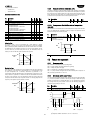
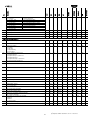
1
µC2SE for process chiller Electronic controller ENG User manual Integrated Control Solutions & Energy Savings ATTENTION DISPOSAL CAREL bases the development of its products on several years’ experience in the HVAC field, on continuous investment in technological innovation of the product, on rigorous quality procedures and processes with in-circuit and function tests on 100% of its production, on the most innovative production technologies available on the market. CAREL and its branch offices/affiliates do not guarantee, in any case, that all the aspects of the product and the software included in the product will respond to the demands of the final application, even if the product is built according to state-of-the-art techniques. The client (builder, developer or installer of the final equipment) assumes every responsibility and risk relating to the configuration of the product in order to reach the expected results in relation to the specific final installation and/or equipment. CAREL in this case, through specific agreements, can intervene as consultant for the positive result of the final start-up machine/application, but in no case can it be held responsible for the positive working of the final equipment/apparatus. INFORMATION FOR THE USERS REGARDING THE CORRECT HANDLING OF WASTE ELECTRIC AND ELECTRONIC EQUIPMENT (WEEE) With reference to European Parliament and Council Directive 2002/96/EC issued on 27 January 2003 and the related national implementation legislation, please note that: WEEE cannot be disposed of as municipal waste, said waste must be collected separately; the public or private waste collection systems defined by local legislation must be used. Moreover, the equipment can be returned to the distributor at the end of its working life when buying new equipment; this equipment can contain hazardous substances: improper use or incorrect disposal of such may have negative effects on human health and on the environment; the symbol (crossed-out wheeley bin) shown on the product or on the packaging and on the instruction sheet indicates that the equipment has been introduced onto the market after 13 August 2005 and that it must be disposed of separately; in the event of illegal disposal of electrical and electronic waste, the penalties are specified by local waste disposal legislation. The CAREL product is a state-of-the-art product, whose operation is specified in the technical documentation supplied with the product or can be downloaded, even prior to purchase, from the website www.carel.com. Each CAREL product, in relation to its advanced technological level, needs a phase of definition / configuration / programming / commissioning so that it can function at its best for the specific application. The lack of such phase of study, as indicated in the manual, can cause the final product to malfunction of which CAREL cannot be held responsible. Only qualified personnel can install or carry out technical assistance interventions on the product. The final client must use the product only in the manner described in the documentation related to the product itself. Materials warranty: 2 years (from the date of production, excluding consumables). Type-approval: the quality and safety of CAREL S.P.A. products are guaranteed by the design system and ISO 9001 certified production. Without excluding proper compliance with further warnings present in the manual, it is stressed that in any case it is necessary, for each CAREL product: Not allow the electronic circuits getting wet. Rain, humidity and all types of liquids or condensate contain corrosive mineral substances that can damage the electrical circuits. In any case, the product should be used and stored in environments that respect the temperature and humidity limits specified in the manual; Not to install the device in a particularly hot environments. Temperatures that are too high can shorten the duration of the electronic devices, damaging them and distorting or melting the parts in plastic. In any case, the product should be used and stored in environments that respect the temperature and humidity limits specified in the manual; Not to try to open the device in any way different than that indicated in the manual; Not to drop, hit or shake the device, because the internal circuits and mechanisms could suffer irreparable damage. Not to use corrosive chemical products, aggressive solvents or detergents to clean the device; Not to use the product in application environments different than those specified in the technical manual. All the above reported suggestions are also valid for the control, serial boards, programming keys or however for any other accessory in the CAREL product portfolio. CAREL adopts a continuous development policy. Therefore, CAREL reserves the right to carry out modifications and improvements on any product described in this document without prior notice. ATTENTION: separate the probe cables and the digital input cables as much as possible from the inductive load and power cables to prevent possible electro-magnetic interference. Never introduce power cables and signal cables (including those of electric control board) into the same cable troughs. The technical data in the manual can undergo modifications without forewarning. The liability of CAREL in relation to its own product is governed by CAREL’s general contract conditions edited on the www.carel.com and/or by specific agreements with clients; in particular, within the criteria consented by the applicable norm, in no way will CAREL, its employees or its branch offices/affiliates be responsible for possible lack of earnings or sales, loss of data and information, cost of replacement goods or services, damage to objects or persons, work interruptions, or possible direct, indirect, accidental, patrimonial, coverage, punitive, special or consequential damage in any way caused, be they contractual, out-of-contract, or due to negligence or other responsibility originating from the installation, use or inability of use of the product, even if CAREL or its branch offices/affiliates have been warned of the possibility of damage. 3 4 Index 1. Introduction .............................................................................................................................................................................................................................................. 7 General description ....................................................................................................................................................................................................................7 Codes .............................................................................................................................................................................................................................................7 Accessories....................................................................................................................................................................................................................................7 Installation .................................................................................................................................................................................................................................................9 2.1 Type of fixing and dimensions .................................................................................................................................................................................................9 2.2 Operational layouts.....................................................................................................................................................................................................................9 2.3 µC2SE wiring diagram .............................................................................................................................................................................................................. 10 2.4 I/O board wiring diagram....................................................................................................................................................................................................... 10 2.5 Optional connections .............................................................................................................................................................................................................. 10 2.6 Inputs/outputs labelling .......................................................................................................................................................................................................... 10 2.7 Connection with CONV0/10VA0 and CONVONOFF0 modules (accessories) .......................................................................................................... 11 2.8 Installation .................................................................................................................................................................................................................................. 11 2.9 Programming key (copy of the set-up)............................................................................................................................................................................... 12 User interface ........................................................................................................................................................................................................................................ 13 3.1 Display ........................................................................................................................................................................................................................................ 13 3.2 Keypad ........................................................................................................................................................................................................................................ 13 3.3 Example: timer reset ................................................................................................................................................................................................................ 13 3.4 Programming ............................................................................................................................................................................................................................ 14 3.5 Menu structure ......................................................................................................................................................................................................................... 14 Commissioning ..................................................................................................................................................................................................................................... 15 4.1 Firmware version ...................................................................................................................................................................................................................... 15 4.2 Configuration ............................................................................................................................................................................................................................ 15 4.3 Minimum and maximum fan speed calculation ............................................................................................................................................................... 16 Functions ................................................................................................................................................................................................................................................ 17 5.1 Set point ..................................................................................................................................................................................................................................... 17 5.2 Probes (analogue inputs)....................................................................................................................................................................................................... 17 5.3 Probe reading............................................................................................................................................................................................................................ 18 5.4 Digital inputs ............................................................................................................................................................................................................................. 18 5.6 Analogue outputs ..................................................................................................................................................................................................................... 19 5.7 Compensation........................................................................................................................................................................................................................... 19 5.8 Low load ..................................................................................................................................................................................................................................... 19 Control .................................................................................................................................................................................................................................................... 21 6.1 Anti-freeze .................................................................................................................................................................................................................................. 21 6.3 Anti-freeze automatic switch-on ........................................................................................................................................................................................... 21 4 6.3 Anti-freeze with EVD ............................................................................................................................................................................................................... 21 6.4 Compressors management ................................................................................................................................................................................................... 21 6.5 Pump management ................................................................................................................................................................................................................. 23 6.6 Compressor – evaporator pump/valve delays .................................................................................................................................................................. 24 6.7 Fan management ..................................................................................................................................................................................................................... 24 6.8 Hot gas bypass .......................................................................................................................................................................................................................... 25 6.9 Pump down ............................................................................................................................................................................................................................... 25 6.10 Heaters management.............................................................................................................................................................................................................. 26 Parameters table ................................................................................................................................................................................................................................... 27 2 7.1 Parameters table µchiller SE for process chiller ................................................................................................................................................................ 27 7.2 Variables accessible only by supervision ............................................................................................................................................................................ 34 Alarms ..................................................................................................................................................................................................................................................... 35 8.1 Type of alarms .......................................................................................................................................................................................................................... 35 8.2 Alarms description ................................................................................................................................................................................................................... 36 8.3 Alarm digital inputs/outputs .................................................................................................................................................................................................. 38 Technical specifications....................................................................................................................................................................................................................... 39 9.1 Software revisions .................................................................................................................................................................................................................... 40 1.1 1.2 1.3 2. 3. 4. 5. 6. 7. 8. 9. 5 6 1. INTRODUCTION 1.1 General description 1.3 Accessories 2 µC SE for process chiller is a compact electronic controller designed for the complete management of the process chiller with 1 refrigerating circuit: it can control air-water and water-water machines. The controller has 5 digital inputs, 5 digital outputs, 4 analogue inputs and 1 analogue output. It can be installed: individually; 4 connected to the tLAN network with the EVD driver to manage the electronic expansion valve; connected in tLAN network with inputs/outputs expansion board. 1.3.1 The PWM output can be converted using the following modules: • CONV0/10A0: conversion from PWM output for SSR into a linear analogue signal 0...10 Vdc and 4...20 mA; • CONONOFF0: conversion from PWM output for SSR into an On/Off output from relay. 1.1.1 The board, connected in tLAN network to the controller, has 5 digital inputs and 5 digital outputs. The switch-over of every digital input can be associated to a determined alarm signal, shown on the controller display and also to a switch-over on the selected digital output. Main functions Briefly: control of: compressor, condenser fan, water pump for evaporator and/or condenser, anti-freeze heaters, alarm signal devices; regulation of the set-point on evaporator input probe (B1), evaporator output probe (B2) or differential (B1-B2); condenser fan/pump speed control; complete alarms management; elimination of storage vessel in event of low load; 4 serial connection to the EVD driver for control of the electronic expansion valve; serial connection to the I/O expansion board for: 1. connection of devices (thermostats/pressure switches) to digital inputs of the I/O board; 2. display of further warnings/alarms on the controller display; 3. selection of the digital outputs to switch-over. 1.3.2 Driver for electronic expansion valve (code EVD0000400 - tLAN) The driver, connected in tLAN network to the controller, allows to control the electronic expansion valve in the cooling circuits. The condensation pressure probe must be connected to the controller, which will send it to the driver. See the manual code +030220227. 1.2 Codes Description 2 µC SE 1 circuit, 2 compressors, panel assembly 2 µC SE 1 circuit, 2 compressors, panel assembly (20 pieces) 2 µC SE I/O board 2 RS485 optional board for µC SE 2 Programming key for µC SE with 230 V power supply unit PWM-On/Off converter board PWM-0...10 V converter board Temperature probes: *** depending on the length (015= 1.5 m, 030= 3 m, 060=6 m) Pressure probes for condenser control ** depending on the pressure (13= 150 PSI, 33= 500 PSI) Connectors kit for code MCH2000051 (multi-pack 20 pieces) Minifit connectors kit +cables measuring 1 m for code. MCH2** Minifit connectors kit +cables measuring 2 m for code. MCH2** Minifit connectors kit + cables measuring 3 m for code. MCH2** Remote terminal for MCH2000050 for panel assembly Remote terminal for MCH2000050 for wall assembly Serial connection kit for remote terminal supervisor Boards with PWM output for fan speed control: 4A/230 Vac 8A/230 Vac 12A/230 Vac 10A/230 Vac 1 piece 10A/230 Vac 10 pieces I/O board (code MCH2000060) 1.3.3 Code MCH2000050 MCH2000051 MCH2000060 MCH2004850 PSOPZKEYA0 CONVONOFF0 CONV0/10A0 NTC***WP00 Fan speed management board (code MCHRTF*) The single-phase voltage regulators MCHRTF use the phase cut principle to regulate the rms voltage leaving the load, on the basis of the PWM command signal phase. A typical application is that of regulating the speed of the condenser single-phase fans, on the basis of the pressure or temperature measured on the heat exchanger itself. SPKT00**R0 MCH2CON001 MCHSMLCAB0 MCHSMLCAB2 MCHSMLCAB3 MCH200TP00 MCH200TW00 MCH200TSV0 MCHRTF04C0 MCHRTF08C0 MCHRTF12C0 MCHRTF10C0 MCHRTF10C1 7 µC2SE process chiller +030220416 - rel. 2.2 - 25.01.2013 1.3.4 Fan speed management board (code FCS3*) 1.3.8 The FCS range appliances are electronic three-phase voltage regulators that use the phase cut principle to regulate the output voltage supplied to the load, depending on the command signal applied to the input. They can drive asynchronous electric motors connected, for example, to axial fans, pumps, mixers, stirrers etc. 1.3.5 Remote terminal (code MCH200T*00) Allows the complete configuration of the remote controller. The use of the keys and the indications on the display faithfully reproduce the µC²SE user interface. It is also possible to connect the PlantVisor to the remote control terminal via relative accessory. The version exists for panel assembly (MCH200TP00) and for wall assembly (MCH200TW00). For further information see the instruction sheet +050001065. CONVONOFF0 module Converts a PWM signal for relay in solid state into ON/OFF output obtained with a relay. The relay boards with CONVONOFF0 code, allow the ON/OFF management of the condenser fans. The command relay has a changeable power of 10 A at 250 Vac into AC1 (1/3 HP inductive). 1.3.9 Programming key (code PSOPZKEY*0) The programming keys PSOPZKEY00 and PSOPZKEYA0 for CAREL controllers allow 2 the copying of the complete set of parameters of the µC SE. The keys must be connected to the connector (AMP 4 pin) envisioned in the controllers and can operate with controllers powered or not. The main upload/download functions envisioned are selected via two micro switches. These are: • loading the parameters of a controller into the key (UPLOAD); • copying the key onto one or more controllers (DOWNLOAD). 1.3.6 Analogue output module(code CONV0/10A0) Converts a PWM signal for relay in solid state into an output 0…10 Vdc or 4…20 mA. The three-phase regulators of the FCS range can be connected to the controller without the use of this module. 1.3.7 RS485 Converter (code MCH2004850) Allows the controller to be connected to a supervision network with RS485 standard serial line. To do this, it is used the input normally engaged for the programming key with the double function of key input/serial communication port. 8 µC2SE process chiller +030220416 - rel. 2.2 - 25.01.2013 2 INSTALLATION 2.1 Type of fixing and dimensions 2 4 µC SE for process chiller is supplied with connectors of different format to facilitate the electric connections. The EVD driver and the I/O board must be installed on DIN guide. Dimensions (mm) 2.2 Operational layouts 2 4 Below find the structure of the tLAN network, with the µC SE controller for process chiller, which can operate alone or with the I/O expansion board. The EVD driver is an optional. NETWORK STRUCTURE Key T P B1 B2 B3/B4 C E R FL CMP1/2 EV EEV F EP CP AIR - WATER CHILLER Evaporation temperature Evaporation pressure Evaporator input probe Evaporator output probe Condenser probe Condenser Evaporator Heater Flow switch Compressor 1/2 Expansion valve Electronic expansion valve Condenser fan Evaporator pump Condenser pump WATER - WATER CHILLER 9 µC2SE process chiller +030220416 - rel. 2.2 - 25.01.2013 2 2.3 µC SE wiring diagram Key G G0 B1…B4 ID1…ID5 C1…C5 NO1…NO5 Y1 Key/SPV V+ Tx/Rx Ground - 24 Vac power supply Power supply reference Analogue inputs 1…4 Digital inputs 1…5 Common digital outputs 1…5 Digital outputs 1…5 normally open contact Analogue output 1 Connector for key/supervisor Ratiometric pressure probe power supply tLAN port Notes: the digital output 1 cannot be programmed and is intended for the compressor; the analogue inputs B1 and B2 are reserved respectively for the evaporator input and output probes. 2.4 I/O board wiring diagram Key G G0 ID11…ID15 B8 C11…C15 NO11…NO15 V+ Y2 Tx/Rx Ground 2.5 Optional connections tLAN port 2.6 Inputs/outputs labelling The programming key input can be used successively for the connection to the supervision network via RS485 converter. 2 Analogue inputs Digital inputs Analogue outputs Digital outputs - ! 24 Vac power supply Power supply reference Digital inputs 11…15 Analogue input 8 Common digital outputs 11…15 Digital outputs 11…15 normally open contact Ratiometric pressure probe power supply Analogue output 2 µC SE B1…B4 ID1…ID5 Y1 NO1…NO5 I/O expansion board B8 ID11…ID15 Y2 NO11…NO15 Notes: only probe B8 can be connected to the I/O expansion board; the numbering of the digital inputs/outputs of the expansion board goes from 11 to 15. If the serial line is connected in supervision mode, do not connect to earth the secondary terminal of the supply transformer of the control. 10 µC2SE process chiller +030220416 - rel. 2.2 - 25.01.2013 2.7 Connection with CONV0/10VA0 and CONVONOFF0 modules (accessories) The CONV0/10AVA0 and CONVONOFF0 modules allow to convert a PWM output for SSR respectively into an analogue output 0…10Vdc and into an ON/OFF output with relay. Note that with the same controller 3 different types of outputs can be obtained. Key CONV0/10A0 - CONVONOFF0 module Terminal Description 1 24 Vac power supply 2 Power supply reference 3 PWM (+) command signal 4 PWM (-) command signal CONV0/10A0 module Terminal Description 5 0...10 Vdc output reference 6 0...10 Vdc output 7 4...20 mA output reference 8 4...20 mA output CONVONOFF0 module Terminal Description 5 Normally open 6 Common 7 Normally closed 8 Not connected The command signal to terminals 3 and 4 of the CONV0/10VA0 and CONVONOFF modules is optically-isolated. This allows the power supply G, G0 can be in common with the controller power supply. 2.8.2 Electric connections 2.8 Installation Proceed as follows for installation, making reference to the wiring diagrams: 1. Connect probes and power supply: the probes can be installed up to a maximum distance of 10 metres from the controller as long as shielded cables with 2 minimum section of 1 mm are used. To improve immunity to interference, it is recommended to use probes with shielded cable (connect just one end of the shield to the electric control board earth). 2. Program the controller: see the “User interface” chapter. 3. Connect the actuators: it is preferable to connect the actuators only after having programmed the controller. It is recommended to carefully evaluate the maximum capacities of the relays indicated in the “technical specifications”. 4. Connect the serial network: if the connection to the supervision network is envisioned via the relevant serial boards (code MCH2004850), the system must be earthed. Make sure there is just one earth connection. In particular, the transformers secondary device, which powers the controllers, must not be connected to earth. If connection to a transformer with earthed secondary device is necessary, an isolation transformer must also be used. It is possible to connect several controllers to the same isolation transformer, however it is recommended to use one isolation transformer for every controller. Case 1: several controllers connected in network powered by the same transformer (G0 not connected to earth). Typical application of several controllers inside the same electric control board 2.8.1 General warnings ! Disconnect power supply before working on the board during assembly, maintenance and replacement. Do not install the controllers in environments with the following features: • relative humidity over 90% or condensing; • strong vibrations or blows; • exposure to continuous jets of water; • exposure to aggressive and polluting atmospheres (e.g. sulphuric and ammonia gases, saline mists, fumes) to prevent corrosion and/or oxidation; • high magnetic and/or radiofrequency interference (avoid installation of the equipment near to transmitting antennas); • exposure of the controllers to direct solar radiation and atmospheric agents in general. The following recommendations must be respected when connecting the controllers: • the incorrect connection to the power supply voltage can seriously damage the controller; • separate the probe cables and the digital input cables as much as possible (at least 3 cm) from the inductive load and power cables to prevent possible electromagnetic interference. Never introduce power cables and probe cables (including those of electric control board) into the same cable conduits. • do not install the probe cables in the immediate vicinity of power devices (switches, magnet circuit breaker switches, etc.). Reduce the probe cable pathway as much as possible and do not allow routes that enclose power devices; • do not power the controller directly from the main panel power supply if also supplying power to other devices, such as switches, solenoid valves etc. which will require another transformer. The controller is not an appliance that guarantees electrical safety, but simply suitable operation: to prevent a dangerous situation being generated following a short circuit or overload, the customer must install suitable electro-mechanical cut-off devices on the lines of interest (fuses or similar). 11 µC2SE process chiller +030220416 - rel. 2.2 - 25.01.2013 Case 2: several controllers connected in network powered by the different transformers (G0 not connected to earth). Typical application of several controllers that are part of different electric control boards. UPLOAD - copy parameters from controller to key 2.9.1 Procedure: open the rear door of the key and position the two dip-switches at OFF. Close the door; connect the key to the controller terminal; press the key button and hold, checking the signalling sequence of the LED: from red, it turns green after a few seconds; if the signalling sequence is that indicated above, the copying operation has been successful (green LED on); the button can be released and the key disconnected from the instrument. In the event of different signals: if the green LED does not switch on or if flashing, there is a problem. See the following table for the meanings of the signals. ! Procedure: open the rear door of the key and position dip-switch n. 1 at OFF and dipswitch n. 2 at ON. Close the door; connect the key to the controller; press the key button and hold, checking the signalling sequence of the LED: from red, it turns green after a few seconds; if the signalling sequence is that indicated above, the copying operation has been successful (green LED on); the button can be released. After a few seconds the LED switches off and the key can be disconnected from the instrument; in the event of different signals: if the green LED does not switch on or if flashing, there is a problem. See the relative table for the meanings of the signals. The operation is completed in 10 seconds. If the completed signal with green LED on is not given within this time period, it is good practice to attempt the operation again, releasing and pressing the button again. In the event of flashing, see the relative table for the meaning of the signal. 2.8.3 Protection against electric shock and maintenance warnings The system made up of the control board (MCH200005*) and the other optional boards (MCH2000060, MCH2004850, MCHRTF****, CONVONOFF0, CONV0/10A0, EVD000040*) constitutes a control device to be integrated into class I or class II appliances. The class of protection against electric shock depends on how the control device is integrated into the unit built by the manufacturer. The protection against short circuits due to faulty wiring must be guaranteed by the manufacturer of the appliance that the controller will be fitted on. 2.9 Programming key (copy of the set-up) The PSOPZKEY00 and PSOPZKEYA0 programming keys for CAREL controllers allow 2 to copy the complete set of µC SE parameters. The keys must be connected to the connector (AMP 4 pin) envisioned in the controllers and can operate with instruments that are live or not, according to that indicated in the user notes of the specific controller. There are two main functions envisioned and they are selected via two dip switches (situated under the battery lid). These are: loading the parameters of a controller into the key (UPLOAD); copying the key onto one or more controllers (DOWNLOAD. Fig.1 DOWNLOAD - copy the parameters from the key to controller 2.9.2 Attention: 2 If one transformer is used to supply both the μC SE and the accessories, all the G0 terminals on the various controllers or the various boards must be connected to the same terminal on the secondary, and all the G terminals to the other terminal on the secondary, so as to avoid damaging the controller; for use in residential environments, use shielded cable (two wires + shield earthed at both ends, AWG 20-22) for the tLAN connections (EN 55014-1); avoid short-circuits between V+ and GND so as not to damage the controller. perform all the maintenance and installation operations when the unit is not connected to the power supply; separate the power cables (relay outputs) from the cables corresponding to the probes, digital inputs and serial line; use a transformer dedicated exclusively to the electronic controllers for the power supply. Fig.2 signal LED red LED flashing error meaning and solution Batteries flat start copy Green LED flashing Batteries flat copy end (only for PSOPZKEY00) Flashing simultaneously red/green LED (signal orange) Instrument not compatible Red and green LEDs on Copy error Red LED on stable Data transfer error LEDs off Batteries disconnected Power supply unit not connected The batteries are flat, the copy cannot be made. Replace the batteries (only for PSOPZKEY00). The copy operation has been performed correctly but at the end of the operation the battery voltage is low. The parameters set-up cannot be copied because the controller model connected is not compatible. This error only for DOWNLOAD function, check the controller code and copy only onto compatible codes. Error in the data copied. Repeat the operation, if the problem persists, check the batteries and key connections. The copy operations has not terminated due to serious data transfer or copy errors. Repeat the operation, if the problem persists, check the batteries and key connections. Check batteries (for PSOPZKEY00) ! Parameters can only be copied via controllers with the same code. The data loading operation into the key (UPLOAD) is always allowed. To facilitate identification of the key to be used, CAREL has enclosed a label on which the programming loaded can be described or the machine to which it refers. Check power supply unit (for PSOPZKEYA0) 2 The key can only be used on µC SE controllers that have the same Firmware version. 12 2 µC SE process chiller +030220416 - rel. 2.2 - 25.01.2013 3 USER INTERFACE The front panel contains the display and keyboard, made up from 4 keys, which, pressed individually or together, allow to perform all of the controller programming operations. 3.1 Display The display features 3 digits, with the display of the decimal point between -99.9 and 99.9. Outside of this range of measurement, the value is automatically displayed without the decimal (even if internally the unit still operates considering the decimal part). In normal operation, the value displayed corresponds to the temperature read by probe B1, that is, the evaporator water inlet temperature*. During the programming it shows the codes of the parameters and their value. (*) Viewing of the standard display can be changed via parameter b00. Icon Colour 1, 2 3, 4 Amber Amber Amber Amber Amber Amber Amber Red Amber Amber Meaning With LED on Compressor 1 and/or 2 on Not used At least 1 compressor on Condenser pump/fan on Condenser fan active Not used Heater on Alarm on Not used Chiller mode With LED flashing Start up request Not used Start up request Not used Not used Chiller mode request 3.2 Keypad Key (UP) (DOWN) Machine state Loading default values Return to upper level up to exit (with saving in EPROM) Access to parameters type “Direct” Selection and display of type“Direct” parameter value Confirm parameter value variation Pressure mode Controller power supply with key pressed Single press Single press Parameters programming via introduction of password Press for 5 s Value increase Selection of successive parameter Immediate access to values read by the probes (parameters b01, b02,…) Passage from stand-by to chiller mode and vice versa Single of continuous press Single of continuous press Single press Press for 5 s Value decrease Select previous parameter Single or continuous press Immediate access to values read by the probes (parameters b01, b02,…) Single press Press for 5 s Alarms manual reset Immediate timer reset 3.3 Example: timer reset Pressing e simultaneously, in the timer value display phase (e.g. parameter c10), resets the same at zero and consequently cancels the maintenance request. 13 µC2SE process chiller +030220416 - rel. 2.2 - 25.01.2013 Parameters modification procedure: 3.4 Programming 1. Press “ “ and “ ” for 5 s; 2. The and symbols appear along with “00”; The parameters divide into 4 different levels according to their accessibility by the user via password and their function. Entering a certain level it is possible: 1. to access all parameters of the same level and the lower levels (S-P menu); 2. set the desired level for each parameter (L-P menu). 3. Set the password via “ ” and “ ” and confirm with “ 4. Select the parameters menu (S-P) via “ ” and “ 5. Select the parameters category (A,b,c,d..) via “ 3.4.1 Levels 6. Select the parameter via “ “Factory”: accessible with password 66, it allows the configuration of all unit parameters; “Super User”: accessible with password 11, it allows the configuration of the Super User, User and Direct parameters; “User”: accessible with password 22, it allows the configuration of those parameters that can be set typically by the user and Direct, therefore relative to the options. “Direct”: accessible by pressing “ ” for 5 s, it allows to read the probes and any data, which can be interrogated by anyone without compromising unit operation. 7. Modify the parameter value with “ 8. After modification, press “ 9. Press “ Max U.M. Default parameters setting 0/1 = enabled/disabled Min H22 Def pressed) set the parameter H22 = 1. Description 0 0 1 - “. Confirm with “ ” and “ ” to confirm or “ “. Confirm with “ ”; ”; ; ” to annul the modification; ” several time until going back to the main Notes: 1.the parameters modified without confirmation via the “ ” key go back to the previous value; 2. if no operations are performed on the keyboard for 60 seconds, the controller exits the parameter modification menu by timeout and the changes are cancelled. 3. to modify the level of a parameter, enter the levels menu L-P and assign the desired level to each parameter. . To enable the setting procedure for parameters at default values (controller power Par. ” and “ ”; ” to return to the previous menu; 10. To save the modifications, press “ menu. 3.4.2 Default parameters setting supply with ” and “ “; “. Confirm with “ 3.5 Menu structure The figure shows the categories of the parameters that can be selected during programming. 14 µC2SE process chiller +030220416 - rel. 2.2 - 25.01.2013 4 COMMISSIONING - 4.2 Configuration The configuration parameters must be set during the commissioning of the controller and concern: the type of chiller: air-water or water-water, number of compressors and partialisation logic, enabling of compressor partialisation in high pressure mode, enabling hot gas and pump down by-pass function; the configuration of the tLAN network: devices connected, type of protocol and serial address; the setting of the device counter, the keyboard block, the modification of the alarm relay state. Min Chiller type 2=Air-water 4=Water-water Number of compressors per circuit 0 =1 compressor on circuit 1 1= 2 compressors tandem on circuit 1 2= Do not select 3= Do not select 4=1 compressor and a partialisation on circuit 1 5= Do not select Evaporator pump 0=Absent 1=Always on 2=On at regulator request 3=On at regulator request and timed Compressor partialisation valve 0 = Normally excited 1 = Normally unexcited 2, 3 = Do not select Pump down 0/1 = disabled/enabled Hot gas by-pass 0/1 = disabled/enabled Hot gas by-pass in stand-by 0/1= disabled/enabled 2 2 4 - 0 0 5 - H12 H13 H25 H26 Max 0 7 - 1 0 1 0 200 1 - 4 Device I/O expansion board 4 EVD Driver tLAN address 3 2 4.2.4 Other configuration parameters (par. c14, /23, H09, P35) c14 establishes the number of operating hours of the compressors/pumps, expressed in hundreds of hours, over which to activate the maintenance request signal (Hc1, Hc2). c10 and c11 are read only parameters and indicate the number of operating hours of the compressors 1 and 2, expressed in hundreds of hours. c15 and c16 are read only parameters and they indicate the number of evaporator and condenser pump operating hours, expressed in hundreds of hours. The maintenance request signal for the pumps is always Hc1. Pressing and simultaneously, in the timer value display phase, resets the same at zero and consequently to the cancellation of the maintenance request. H09 allows to disable the modification of the “Direct” and “User” parameters from keyboard; however it allows to display the parameter values. The timer reset function is also disabled. P35 allows to alter the status of the alarm relay, if it is active. 1 0 3 - 1 0 3 - 0 0 1 - 0 0 1 - 0 0 1 - Par. Description U.M. H05 0 Max H04 Network configuration 0 = Control only 1 = Control + EVD 2, 3 = Do not select 4 = Control + IO 5 = Control + EVD + IO 6, 7 = Do not select RS485 serial address Network protocol 0 = Carel 1 = ModBus The tLAN factory addresses of the I/O expansion board and of the EVD driver are given in the table. The tLAN address of the I/O expansion board is fixed. To modify 4 the address of the EVD driver, consult the manual cod +030220227. U.M. Def H01 H08 4.2.3 tLAN address configuration The controller allows to manage two types of chiller: air-water and water-water. Moreover, the number of compressors per circuit can be 1 or 2 with alternating operation (tandem) or compressor 1 with partialisation valve, powered according to the logic of parameter H12. Rotation is not managed in this case (see the "Regulation" chap.). The hot gas by-pass in temperature mode function allows to increase the temperature of the output water from the evaporator. See the regulation chapter. Description Description H10 H23 4.2.1 Machine parameters (par. H01, H04, H05, H12, H25, H26) Par. Par. U.M. 99.9 999 99.9 Max 0 0 0 Min - Def Software version Driver software version Expansion board I/O software version Min H99 H97 H95 Def Description U.M. Par. Max The tLAN network can be composed just by the controller for process chiller, which will have the inputs/outputs for the standard machine controller. If the thermostatic 4 expansion valve is replaced by the electronic expansion valve, the EVD driver must be connected. If connected, the I/O expansion board allows to configure the digital inputs with 5 new warnings or alarms. Moreover, it allows each individual digital output to change on the basis of an individual alarm. The serial address identifies the controller in a RS485 network with Carel or Modbus protocol. Min 4.2.2 Network parameters (par. H08, H10, H23) On controller switch-on the firmware version of the same can be verified, along 4 with that of the EVD driver and I/O expansion board via the parameters H99, H97 and H95. Def 4.1 Firmware version c10 c11 c14 Compressor 1 timer Compressor 2 timer Maintenance request threshold 0 = function disabled Evaporator pump timer Condenser pump timer Unit of measurement 0/1 = °C/°F Lock keypad 0/1 = disabled/enabled Modify alarm relay status via PRG/mute 0/1=No/Yes 0 0 0 0 0 0 800 800 100 100 h 100 h 100 h 0 0 0 0 0 0 800 800 1 100 h 100 h - 1 0 1 - 0 0 1 - c15 c16 /23 H09 P35 2 15 µC SE process chiller +030220416 - rel. 2.2 - 25.01.2013 4.3 Minimum and maximum fan speed calculation This procedure should only be performed when the fan speed control boards are used (code MCHRTF*). When ON/OFF modules are used (code CONVONOFF0) or alternatively the PWM to 0 to 10 V converters (code CONV0/10A0) are used, parameter F03 should be set to zero, and parameter F04 to the maximum value. Given the different types of motors existing on the market, it must be possible to set the voltages supplied by the circuit board corresponding to the temperatures of minimum and maximum speeds. In this regard (and if the default values are not suitable), proceed as follows: • set the parameter F02=0 and reset F03 and F04 to zero; • the condensation set point has been modified to take the output signal to the maximum value (PWM); • increase F04 until the fan operates at a sufficient speed (make sure that, after having stopped it, it can rotate freely when released); • “copy” this value to parameter F03; this sets the voltage for the minimum speed; • connect a voltmeter (set to AC, 250V) between the two “L” terminals (the two external contacts); • increase F04 until the voltage stabilises at around 2 Vac (inductive motors) or 1.6, 1.7 Vac (capacitive motors); Once the value has been found, it will be evident that even when increasing F04 the voltage no longer decreases. Do not increase F04 further so as to avoid damaging the motor; • restore the correct condensation set point. The operation is now completed. 2 16 µC SE process chiller +030220416 - rel. 2.2 - 25.01.2013 5 FUNCTIONS r13 0.1 0 r14 50 4 °C/°F °C/°F - /01 1 0 1 - 1 0 1 - 0 0 3 - 0 0 4 - /09 Probe B1 0/1 = Absent/present Probe B2 0/1 = Absent/present Probe B3 0 = Absent 1 = Condenser NTC 2 = External NTC 3 = Differential control Probe B4 0 = Absent 1 = Digital input 2 = External NTC 3 = Ratiometric Condenser 4 = Differential control Minimum voltage input value 50 0 /10 Vdc/100 /10 Maximum voltage input value 450 /09 500 Vdc/100 /11 Minimum pressure value 0 0 /12 bar /12 Maximum pressure value 34,5 /11 99,9 bar /13 Probe B1 calibration 0 -12 12 °C/°F /14 Probe B2 calibration 0 -12 12 °C/°F /15 Probe B3 calibration 0 -12 12 °C/°F /16 Probe B4 calibration 0 -12 12 /21 Digital filter 4 1 15 °C/°F /bar - /22 Input limitation 8 1 15 - /02 /03 /04 -40 80 12 30 10 0 -40 r13 r13 r46 -40 0 r14 176 r14 176 r45 23 °C/°F °C/°F °C/°F °C/°F °C/°F - ON OFF r02 U.M. r13 r14 r21 r45 r46 P08/P09/ P34 12 3 0 Max Set point Differential Type of regulation/compressors use 0 = Proportional input 1 = Proportional input + neutral zone 2 = Proportional output 3 = Proportional output + neutral zone 4 = Timed output with neutral zone Minimum set point Maximum set point Set point from external contact Relative control maximum set point Relative control minimum set point Digital input selection ID1/ID2/ID5 nd 13=2 Set point Description Min r01 r02 r06 Par. Def Description Def Par. U.M. The probe parameters allow to: • set the type and function of the probe; • set the offset for the correction of the reading (calibration); • set the maximum/minimum voltage input; • activate a filter to stabilize the measurement. Max 5.2 Probes (analogue inputs) The control algorithm is the ON/OFF type according to the figure. The set point r01 can be set from a minimum value to a maximum value (par. r13, r14). The probe selected for the control depends on parameter r06, once enabled with the parameters /01 and /02. If r06 = 0,1 the probe is B1. If r06 = 2, 3, 4 the control probe is B2. A second set point value can be set from external digital input (par. r21). Instead, setting B3 or B4 as differential control probe, the relative set point control is activated, in which the set point becomes r01 plus the value read by probe B3 or B4. Min 5.1 Set point B1/ B2 r01 ON The probes B1/B2 have the function of input/output evaporator temperature. The probe B3 can be configured as condensation temperature probe, external or differential control. The external probe allows the activation of the external compensation algorithm. The probe B4 can have the same functions as B3 and in addition acts as digital input (can be configured from par. P13). In this case, the condenser probe is ratiometric. OFF B1/ B2 r02 r45 Key r01 r02 B1/B2 B3/B4 r01 + B3 or r01 + B4 r46 Parameters /09, /10, /11, /12 establish the work range of the ratiometric probe. Set point Differential Evaporator input/output probe Differential control probe Example: Input 0…4.5 Vdc on B4, /09=0, /10 = 4.5 V dc, /11 = 5, /12 = 10, /16=0 Display visualization (/16=0) 10 For the explanation of the functions relative to the compressors, see par. 6.4.7. 7,5 5 0 4,5V B4 Therefore 5 will be displayed in correspondence with 0 V and 10 will be displayed in correspondence with 4.5 V. These are also the values on the basis of which control takes place. 2 17 µC SE process chiller +030220416 - rel. 2.2 - 25.01.2013 The parameters /13…/16 allow to correct the measurement shown on the display, adding an offset of the measurement read by the probe: the value assigned to this parameter is added to the probe if positive or removed if negative. P08: as well as the flow switch/pump thermal overload/general alarms with manual or automatic reset, it is possible to configure the digital input for: the set point change from r01 to r21, limited by parameters r13 and r14 (minimum and maximum set-point); On/Off remote. Enabling is given by parameter H07. The parameter /21 allows to establish the coefficient used in digital filtering of the value measured. High values of this parameter allow to eliminate any continuous interference at the analogue inputs (but reduces measurement immediacy). The value recommended is equal to 4 (default). P37: the digital inputs 11…15 of the I/O expansion board can be configured as: warning input Ad1…Ad5: causes only Ad1…Ad5 shown on display; alarm input Ad1…Ad5: causes the display of Ad1...Ad5 and unit switch-off. The parameter /22 allows to establish the maximum variation that can be detected by the probes in a machine program cycle; practically, the maximum variations allowed in the measurement are between 0.1 and 1.5 units (bar, °C or °F depending on the probe and the unit of measurement) about every second. Low parameter values allow to limit the effect of impulse type interference. Recommended value 8 (default). Digital input 1 0=Not used 1=Flow switch alarm with manual reset 2=Flow switch alarm with automatic reset 3=General thermal overload alarm with manual reset 4=General thermal overload alarm with automatic reset 7=Thermal overload alarm with manual reset 6=Thermal overload alarm with automatic reset 7, 8, 9, 10 = Do not select 11=General alarm with manual reset 12=General alarm with automatic reset 13=2°Set-point 14…22=Do not select 23=On/Off remote Digital input On/Off 0/1=Absent/present Minimum set point Maximum set point Set-point from external contact Digital input 2 See P08 Configuration of B4 as digital input if /4=1 See P08 Digital input 5 See P08 Digital input 11 0 = not connected 1…5 = Alarm Ad1…Ad5 6…10 = Warning Ad1…Ad5 Digital input 12 See P37 Digital input 13 See P37 Digital input 14 See P37 Digital input 15 See P37 Display 0 = Probe B1 1 = Probe B2 2 = Probe B3 3 = Probe B4 4, 5, 6 = Do not select 8= Set point without compensation 9 = Set point with compensation 10 = ID remote 11 = Do not select Probe B1 reading Probe B2 reading Probe B3 reading Probe B4 reading b01 b02 b03 b04 U.M. b00 Max Description Min Par. Def b00 allows to set the probe for standard display viewing. b01…b04 are the values read by the probes B1…B4. 0 0 11 - 0 0 0 0 0 0 0 0 0 0 0 0 °C/°F °C/°F °C/°F °C/°F /bar H07 r13 r14 r21 P09 5.3.1 EVD4 driver probes reading 4 The following displays appear only if an external EVD driver is connected, which transmits them to the controller via tLAN. b09: driver evaporation temperature. b10: driver evaporation pressure: value measured of the evaporation pressure. b11: driver superheating = superheated gas temperature – evaporation saturate temperature. b12: saturation temperature = value calculated of the evaporation saturate temperature. b13: valve position as %. b19: condenser output temperature probe. b09 b10 b11 b12 b13 b19 Driver evaporation temperature Driver evaporation pressure Driver overheating Driver saturation temperature Driver valve position Condenser output temperature probe 0 0 0 0 0 0 0 0 0 0 0 0 0 0 0 0 100 0 P13 P34 P37 P38 P39 °C/°F bar °C/°F °C/°F % °C/°F P40 P41 0 0 23 - 0 0 1 - -40 80 12 0 -40 r13 r13 0 r14 176 r14 23 °C/°F °C/°F °C/°F - 0 0 23 - 0 0 23 - 0 0 10 - 0 0 10 - 0 0 10 - 0 0 10 - 0 0 10 - 5.5 Digital outputs 5.4 Digital inputs Regarding the alarm outputs configuration, see the “Alarms” chapter. The following digital output cannot be configured. 2 The inputs ID1…ID5 refer to the µC SE controller. The inputs ID11…ID15 refer to the I/O expansion board. The analogue input B4 can be configured as digital input (par. P13). NO1 Compressor output Parameter H11 allows associating the digital outputs to the unit actuators (see table). The function of the other digital outputs can be configured from parameter. The following digital inputs cannot be configured (see wiring diagram): ID3 ID4 U.M. P08 Max Description Min 5.3 Probe reading Par. Def The warnings/alarms Ad1...Ad5 can be used to switch-over the outputs NO11,....NO15 of the I/O expansion board, along with the high pressure, low pressure alarms, etc. See parameter P42 at the "Digital outputs" paragraph. High pressure alarm input Low pressure alarm input Regarding the alarm inputs, see the “Alarms” chapter. 2 18 µC SE process chiller +030220416 - rel. 2.2 - 25.01.2013 H11 7 compressor 1 heater step 1 heater step 2 alarm 8 compressor 1 heater 1 step condenser fan alarm 4 compressor 1 evaporator pump compressor 2 (or compressor 1 partialization) alarm 5 compressor 1 heater 1 evaporator pump condenser fan 6 compressor 1 heater step 1 - alarm alarm 9 compressor 1 compressor 2 alarm 10 compressor 1 compressor 2 heating step 1 alarm 11 compressor 1 compressor 2 heating step 1 alarm 12 compressor 1 P25 P26 P27 P28 Alarm relay output logic 0/1=Normally unexcited/excited Digital output 2 0 = No function 1 = Compressor 2 2 = Anti-freeze heater/support 1 3 = Do not select 4 = Pump/condenser fan 5, 6, 7 = Do not select 8 = Condenser fan on/off 9 = Anti-freeze heater/support 2 10 = Alarm 11 = Do not select Digital output 3 See P25 Digital output 4 See P25 Digital output 5 See P25 Digital output 11 0 = Not used 1…5 = Ad1…Ad5 6 = High pressure alarm 7 = Do not select 8 = Low pressure alarm 9 = Do not select 10 = Circuit 1 thermal overload 11 = Do not select 12 = Flow switch alarm 13 = Low temperature alarm 14 = High temperature alarm 15 = Low temperature alarm at start-up 16 = High temperature alarm at start-up 17 = Pump overload 18 = Do not select Digital output 12 See P42 Digital output 13 See P42 Digital output 14 See P42 Digital output 15 See P42 P25 P26 P27 P28 P42 P43 P44 P45 P46 UM P21 Max Description Min Par. Def To change the function of the other outputs, operate on the following parameters. 0 0 1 - 0 0 11 - 5.6 Analogue outputs The analogue output Y1 is set-up for the condenser fan and is active if F01 = 1. In systems with hot gas bypass function enabled, the bypass valve is commanded by the output Y1 (controller) or Y2 (I/O expansion board). See the control chapter. 5.7 Compensation The compensation can indifferently increase or decrease the value of r01 depending on whether r17 is respectively positive or negative. r01 varies only if the external temperature (e.g.B3) exceeds r19: if B3 is over r19 there will be: r01 effective = r01 + (B3-r19)*r17 if B3 is lower than r19: St1 effective = St1 0 0 11 - 0 0 11 - 0 0 11 - 0 0 18 - Par. Description r01 r17 Set-point Compensation constant 0 = no compensation Maximum distance from the set-point Start compensation temperature r18 r19 U.M. NO1 NO NO3 NO4 NO5 3 compressor 1 evaporator pump compressor 2 (or compressor 1 partialization) alarm Max alarm 2 compressor 1 heater 1 evaporator pump compressor 2 (or compressor 1 partialization) - Min NO5 1 compressor 1 heater 1 evaporator pump compressor 2 (or compressor 1 partialization) alarm Def NO1 NO2 NO3 NO4 0 compressor 1 heater 1 evaporator pump - 12 0 r13 -5 r14 5 °C/°F - 0,3 30 0,3 -40 20 176 °C/°F °C/°F r01_comp r01+r18 r17=2 r17= +0,5 r01 r01-r18 r17= -0,5 r17= -2 r19 Key r01_comp B3 Compensated set-point 5.8 Low load 0 0 18 - 0 0 18 - 0 0 18 - 0 0 18 - In the systems with reduced water content, a storage tank must be provided, so that there are no continuous and rapid temperature changes in the cooled water following control intermittence. In this way, the number of compressor hourly switch-ons/offs is limited to an acceptable number. The storage tank can be eliminated in low load conditions. Low load condition: 1. only one compressor is active; 2. the compressor is switched off after an operating period less than the value of parameter r28. r28 therefore represents the minimum operating time of the compressor, below which the low load condition is determined. The compressor will analyse the low load status every time the compressor is switched off. If already in low load state, the time considered by the controller for the new analysis becomes r28xr29: r02”. 2 19 µC SE process chiller +030220416 - rel. 2.2 - 25.01.2013 r27 Accumulation vessel suppression (low load) 0=Disabled 1=Enabled 2=Do not select 3=Do not select Min. compressor running time for low load Low load differential r28 r29 t a n k U.M. Description Min Max Par. Def The low load differential is r29. This parameter represents the new differential considered by the controller during the low load condition. Specifically r02 is replaced by r29. 0 0 3 - 60 3 0 999 1 50 s °C/°F u s e r s evaporator 2 20 µC SE process chiller +030220416 - rel. 2.2 - 25.01.2013 6 CONTROL ON 6.1 Anti-freeze Anti-freeze alarm set-point Anti-freeze alarm set-point limit Anti-freeze alarm differential Anti-freeze alarm delay time from switch-on 3 -40 A07 -40 A04 176 °C/°F °C/°F 5 0.3 122 °C/°F 0 0 150 s OFF S3 A14 + A02 A14 t Key A14 S3 Differential Time ON 6.4.1 c05) OFF The parameters in question regard the minimum operating times or switch-off times of the same output or different outputs, with the purpose of protecting the compressor and preventing regulation oscillations. B2 For the times set to become operational, switch the controller off and back on again after programming. Anti-freeze differential 6.4.2 c03) 6.2 Anti-freeze automatic switch-on 0 3 - Compressor minimum switch-on time Compressor minimum switch-off time Delays between switch-ons of the same compressor 60 0 60 0 360 0 999 999 999 s s s 6.4.3 Protection for outputs with different relays (par. c04, c05) 4 Def c04 c05 Switch-on delay between 2 compressors 10 Switch-off delay between 2 compressors 0 A07 A04 0,3 122 U.M. Min Max Def 3 5 0 0 999 999 s s c03 c01 Par. Description U.M. c04 establishes the minimum time that must pass between successive switch-ons of 2 compressors. By delaying the connection, line overloads are prevented due to close or simultaneous peaks, c05 establishes the minimum time that must pass between the switch-off of the two compressors. Par. Description 4 With the EVD driver connected, A14 represents the evaporation temperature transmitted by the driver, below which the anti-freeze alarm is activated; when the alarm is active, the compressors in the circuit affected are switched off, while the pump remains on to reduce the possibility of freezing. Reset (manual or automatic, see par. P05) only occurs when the water temperature exceeds A14+A02. A14 Anti-freeze EVD alarm set point A02 Anti-freeze alarm differential U.M. U.M. 0 c01 c02 c03 Max 6.3 Anti-freeze with EVD Max Anti-freeze automatic switch-on 0 = Disabled 1 = Heaters and pumps on simultaneously on A4 2 = Do not select 3 = Heaters on at A4 Min A10 Def Description Par. Description Max c01 establishes the minimum activation time of the output, independently from request. c02 establishes the minimum switch-off time if the output, independently from request. c03 establishes the minimum time between two successive switchons of the same output. The parameter A10 has effect if the unit is in stand-by. A10 = 1: auxiliary heater (if enabled) and pump are on at the same time on the basis of the set point A04; A10 = 2: do not select; A10 = 3: heaters only on, on the basis of the set point A04. Par. Protection for the output at relay (par. c01, c02, Min A02 Def Anti-freeze set-point Anti-freeze probe Digital outputs at relay (par. c01, c02, c03, c04, ! A01 4 A02 t 6.4 Compressors management A02 Key A01 B2 4 Anti-freeze EVD alarm set-point 4 EVD evaporation temperature probe Min A03 U.M. A01 A07 Max Description Min Par. Def The anti-freeze probe is B2. The anti-freeze set-point A01 represents the temperature below which the machine passes to anti-freeze mode: alarm A1 activates and switches the alarm output. The value of A01 is limited by A07. A03 is the intervention delay time of the anti-freeze alarm when starting the machine. A02 A1 ALARM c02 ON CMP1 °C/°F °C/°F OFF ON CMP2 OFF c04 Key t Time 2 21 CMP1/2 c05 t Compressor 1/2 µC SE process chiller +030220416 - rel. 2.2 - 25.01.2013 6.4.4 Maximum operating time of compressor in tandem (par. c09) 6.4.7 r07: neutral zone. The neutral zone moves the proportional band by r07 from the set-point and is valid in all configurations, if enabled by parameter r06. r06: compressors regulation type. This parameter allows to set the logic for maintenance of the set-point. r07 U.M. min Type of regulation/compressors use 0 = Proportional Input 1 = Proportional Input + neutral zone 2 = Proportional output 3 = Proportional Output + neutral zone 4 = Timed output with neutral zone Neutral zone differential Max 60 r06 Min U.M. 0 Par. Description Def Max Maximum operating time of compressor 0 in tandem 0 = function disabled Min c09 Def In the case of 2 tandem compressors, it must be prevented that a compressor of the same circuit works over the time set (c09), if the other remains off. This to prevent the oil in common from migrating over that allowed towards the active compressor, thus preventing that the next start-up of the compressor remaining unused (FIFO logic) causes serious problems due to poor lubrication. Therefore the compressor 1 (or 2), if it must operate continuously, after time c09 will switch off leaving the task to the other, which was off. This function considers the compressor protections. A c09 value lower than a c03 value is ignored and the compressors exchange after time c03. Par. Description Regulation type/ compressor use (r06, r07) 0 0 4 - 2 1 50 °C/°F r06 = 0: proportional input 6.4.5 Compressor partialization in high pressure mode (par. P04) 6.4.6 Min Max U.M. P04 Enabling of compressor partialisation in high pressure mode 0=Deactivated 1=Activated 2=Do not select 3=Do not select Def The parameter enables or disables partialisation of the circuit in high pressure mode. The function is valid if the unit is provided with tandem or partialized compressors and pressure transducers. In the event of a high pressure alarm, i.e. values over P18 (with hysteresis of 0.5 bar), the controller disables one power step of the circuit of interest and waits for 10 seconds. When this interval has expired, if the alarm is still active, the unit is stopped otherwise it continues to operate in partialised mode. In this condition, the indication PH1 is displayed. This condition remains active while the pressure does not drop below the value corresponding to the maximum condenser fan speed (F05+F06). The unit re-enables the power step below this limit. Par. Description 0 0 3 - CMP1 ON CMP2 OFF OFF r02 B1 B1 r02 r01 r01 r06 = 1: proportional input + neutral zone CMP1 ON CMP1 ON CMP2 OFF OFF r07 B1 r02 B1 r02 r07 r01 r01 r06 = 2: proportional output CMP1 ON CMP1 ON CMP2 Compressors rotation (par. r05) Min Max U.M. Compressors rotation 0 = Disabled 1 = FIFO type 2 = Hours balancing 3 = Do not select Def Par. Description 0 0 3 - OFF OFF The rotation of the compressors allows the operating hours to be balanced either statistically, using FIFO logic, or absolutely, by counting the effective operating hours. Settings: r05=0: rotation disabled. The customer can use compressors with different power ratings according to the desired logic or manage the partialisation, activating/deactivating them in proportional mode. r05=1: rotation with FIFO logic for switch-on/off (the first to be switched on will be the first to be switched off and vice versa). In this way the operating hours will be optimised along with the compressor peaks, even if the compressor times will always be respected. r05=2: rotation with hours control. The compressors will have the same operating hours, as the compressor with the least operating hours is always started first, again observing the safety times. This does not however consider FIFO logic and does not optimise the starts and stops; r05=3: do not select. r05 CMP1 ON r02 B2 B2 r02 r01 r01 r06 = 3: proportional output + neutral zone CMP1 ON CMP1 ON CMP2 OFF OFF r07 r02 B2 r07 r02 B2 r01 r01 Key r01 r02 CMP1/2 r07 Set point Differential Compressor 1/2 Neutral zone differential 6.4.8 t B1 B2 Time Evaporator input probe Evaporator output probe Timed output with neutral zone (r06 = 4) This type of regulation originates from the requirement to keep the output temperature as constant as possible, in spite of the fact that the load is variable, or the system inertia is reduced. The logic has the objective of maintaining the temperature inside the neutral zone. If outside, the compressors are activated with the logic described below, to return to neutral area, not too quickly (with integral or derivative action) or too slowly (with fixed time logic). Note: the FIFO or timed rotation logic is not valid in the event of compressor partialised output. 2 22 µC SE process chiller +030220416 - rel. 2.2 - 25.01.2013 2 logic times are considered: activation time deactivation time. 6.4.9 50 999 999 999 999 50 Def Min Max U.M. Outputs activation delay 0 0 999 s 6.4.10 Compressors deactivation external temperature (par.r25) The compressors are deactivated if the external temperature drops below the value of r25. The differential for re-activation is fixed at 1 degree. The resistances can be activated according to the relative set-points. °C/°F s s s s °C/°F Par. Description U.M. 0.1 0 0 0 0 0 c06 Max 2 120 100 120 100 2 °C/°F °C/°F - Min r13 r14 0.1 50 0 4 U.M. Min 12 3 0 Par. Description r25 Compressors deactivation external -40 -40 temperature -40 = function deactivated 80 °C/°F Activation time The activation time is not a set parameter, but a value between 2 selected parameters, i.e r08 and r09. As soon as the neutral zone is exited, the activation time is practically r08, while at differential end r02 the activation time is r09. Within the differential r02, the activation time varies in a linear mode between r08 and r09. This means as you move away from the set, the intervention times are reduced, in order to make the system response more dynamic. Def r07 r08 r09 r10 r11 r12 Set point Differential Type of regulation/compressors use 0 = Proportional input 1 = Proportional input + neutral zone 2 = Proportional output 3 = Proportional output + neutral zone 4 = Timed output with neutral zone Neutral zone differential Output maximum activation time Output minimum activation time Output maximum deactivation time Output minimum deactivation time Compressors deactivation differential Def Par. Description Max Activation/deactivation time r01 r02 r06 Outputs activation delay (par. c06) On switch-on (intended as physical power supply of the controller), the activation of all outputs is delayed by the time set to distribute the absorptions and protect the compressor from repeated switch-ons in the event of frequent power-cuts. This means that, after this delay period, the controller will start to manage the outputs on the basis of the protections and the normal operations functions. ON CMP OFF B3 1 r25 Key CMP Compressor r08 Activation time B3 External probe 6.5 Pumps management r09 B1 6.5.1 r01 Deactivation time In the same way as the activation time, the deactivation time also varies depending on a maximum, i.e. the value set by the parameter r10 in correspondence of the set point temperature and a minimum, determined by parameter r11, in correspondence with the differential end for the deactivation of compressors in this mode, selected via parameter r12. Below this value the deactivation time will be the same as the minimum set to the temperature value A04, beyond which all compressors will be switched off, irrespective of times. On moving away from the set point, a more dynamic process reaction is derived. 6.5.2 Description c17 c18 Pump minimum switch-off time Pump minimum switch-on time c07 r01 U.M. B1 Par. Max r11 r12 Minimum switch-on/off times c17: below find the operating diagram of the pump in burst mode (active with H05 = 3). The burst operation is disabled in stand-by and during an alarm with pump inhibited. On switch-on it is activated after time c17. c18 represents the minimum time during which the pump remains active. See the following paragraph for compressor-pump delays c07 and c08. r10 Deactivation time A01 A04 Pump operation H05 establishes the evaporator pump operating mode. H05 = 0: pump disabled, (the flow switch alarm is ignored) H05 = 1: always on (alarm managed) H05 = 2: switched-on on regulator request (alarm managed) H05 = 3: pump activated at regular ON and OFF intervals (with compressor in OFF) according to parameters c17 and c18. Min r02 Def r07 30 3 0 0 150 15 min min c08 ON CMP OFF ON P OFF c18 Key P t: time pump 2 23 c17 c18 c17 CMP c18 t compressor µC SE process chiller +030220416 - rel. 2.2 - 25.01.2013 (parameters F05-F06). When the compressors switch off, the fan deactivates irrespective of the condensing temperature/pressure. 6.6 Compressor – evaporator pump/valve delays 6.6.1 F02 = 3: on when the relative compressor is active with speed control. When the compressor switches off, the fan also switches off irrespective of the condensing temperature/pressure. If the condenser probe is the NTC type, on compressor switch-on, there is fans peak at maximum speed for time F11, irrespective from the temperature measured. In the event of broken condenser probe, the fans are off. Compressor-pump delays (par. c07, c08) c07: if the evaporator pump is on at request of the regulator (H05 = 2), if necessary, the compressor is enabled after the time set. If the pump is always on (H05 = 1) it is activated after the times set by unit switch-on (c06). F03 is the minimum threshold for the triac. If FCS, CONVONOFF0, CONV0/10A0 regulators are used, set this parameter at 0. Pump-compressor switch-on delay Compressor-pump switch-off delay c08 U.M. c07 Max Description Min Par. Def c08: with the pump on by regulator call (H05=2), in the event of compressor switch-off, regulation first pilots compressor deactivation and then that of the pump. If the flow pump is always on (H05=1), it is only deactivated in standby. 20 0 999 s 1 0 150 min F034 is the maximum threshold for the triac. If FCS, CONVONOFF0, CONV0/10A0 regulators are used, set this parameter at 100. F05 is the temperature/pressure set for fan speed. It determines the temperature or pressure below which the fan remains a minimum speed. In the case of regulation ON/OFF represents the temperature or pressure below which the fan is off. F06 is the temperature/pressure differential. If the speed controller is used, it represents the differential with respect to F05 of the temperature or pressure, above which the fan is activated at maximum speed. In the case of regulation ON/OFF represents the differential above which the fan is on. ON P F07 is the temperature/pressure differential for switch-off. If the speed controller is used, it represents the differential, with respect to F05, below which the fans switch off. Switch-on has a hysteresis of 1 °C or 0.5 bar if used for the condenser controller, respectively for temperature or pressure probe. OFF ON CMP OFF 6.7.2 c07 Key P 6.6.2 t: time Pump F11 is the fan peak time. It establishes the operating time at maximum speed at fan switch-on in order to combat mechanical inertia of the motor. The same timing is respected also on switch-on of the compressor (irrespective of condenser temperature/pressure), if the NTC temperature probe is selected for condenser controller and the speed control is enabled F02=3); this takes place in order to anticipate the sudden pressure increase (to which a just as quick temperature increase in the area where the probe is positioned does not necessarily correspond) and consequently improve regulation. If F11 = 0 the function is disabled, i.e. the fans are activated at minimum speed and then controlled on the basis of the condensation temperature/pressure. t c08 CMP Compressor Valve-compressor switch-on delay U.M. Valve-compressor switch-on delay Max c19 Min Description Def c19 represents the delay time necessary to ensure that the valve opens before 4 compressor start-up. The parameter is only available when the EVD driver is connected. Par. 3 0 100 s F12 is the triac impulse duration. It represents the duration of the impulse applied to the triac in milliseconds. For motors with inductive behaviour, set the parameter at 2 (default). Instead, using the CONVONOFF0, CONV0/10A0 modules, FCS regulators, set the parameter at 0. F14 is the forced ventilation time on start-up in condenser high temperature mode. It establishes the forced ventilation time at maximum speed in the event of start-up with condenser high temperature. The function is operational if the condenser probe is temperature and only for air-water chiller. On start-up of the first compressor of the circuit affected, it is assumed that the environment temperature is near to that present on the condenser; if the value measured by the condenser probe exceeds the value F05-F07, the compressor switches on and the fan of the circuit is forced to the max speed for the time set in F14. 6.7 Fan management 6.7.1 Fan switch-on Fan operation F01 enables the condenser fan output, according to the output assigned by parameter H11. Depending on the type of fan, the controller PWM output (Y1), always active, requests the presence of optional boards: 1) CONVONOFF0 for the conversion of the PWM output into ON/OFF output; 2) CONV0/10A0 for the conversion of the PWM output into 0…10 Vdc or 4…20 mA output; 3) optional phase cut boards MCHRTF*/FCS (supplied with Triac). In this case, it is necessary to specify the voltages supplied by the Triac to the fan electric motor, corresponding to minimum and maximum speed. The value set does not correspond to the rms voltage (in Volts) applied but to a calculation unit inside the 2 µC SE. See the Commissioning chap. for the calculation of the fan minimum and maximum speeds. F02 sets the operating mode of the condensation fan. F02 = 0: always on at maximum speed, independently from the compressors. The fan is only off if the unit passes to stand-by; F02 = 1: operation in parallel to compressor. The fan is on at maximum speed when the compressor is active; F02 = 2: on when the corresponding compressor is active, with ON/OFF control based on the temperature/pressure settings for the minimum and maximum speed 2 24 µC SE process chiller +030220416 - rel. 2.2 - 25.01.2013 6.8 Hot gas bypass ON The hot gas by-pass in temperature mode function allows to increase the temperature of the output water from the evaporator. The output enabled is the controller analogue output Y1 (water-water chiller) or Y2 (air-water chiller) of the I/O expansion board. FAN OFF Def Par. Description H25 Hot gas by-pass 0/1 = disabled/enabled H26 Hot gas by-pass in stand-by 0/1 = disabled/enabled 1°C/0.5 bar F04 FAN SPEED Max F05 U.M. B3/B4 Min F06 0 0 1 - 0 0 1 - F03 0% F07 B3/B4 F06 U.M. Max Def 1 - 0 0 3 - 35 75 13 35 3 10 5 0 F03 /11 -40 0 0 0 F04 100 /12 176 30 50 F05 step step bar °C/°F bar °C/°F bar 15 0 50 °C/°F 0 0 120 s 2 0 10 s 0 0 999 s 6.9 Pump down This function allows the unit to be stopped while avoiding the possible formation of liquid refrigerant inside the evaporator. When the only active compressor is called to stop, the expansion valve is closed so as to depressurise the circuit. Valid only when the driver is installed, as the driver pressure probe is used. Par. Description H13 Enable pump down 0 0 H14 Pump down minimum pressure 2 H15 Pump down maximum time 30 2 25 U.M. F07 Minimum fan speed differential in temperature Fans peak speed F11 0 = function disabled F12 Triac impulse duration Fan with high condensing temperature when F14 starting 0 = Disabled 0 Max F03 F04 F05 F05 F06 F06 F07 0 Min F02 Fan 0 = absent; 1 = present Fan: operating mode 0 =Always on 1 = In parallel to compressor 2 = On/Off 3 = Speed control Minimum voltage threshold for Triac Maximum voltage threshold for Triac Fan speed set point in pressure Fan speed set point in temperature Fan speed differential in pressure Fan speed differential in temperature Minimum fan speed differential in pressure Def F01 Min F05 Par. Description 1 - 0 50 bar 0 180 s µC SE process chiller +030220416 - rel. 2.2 - 25.01.2013 6.10 Heaters management r43 Heaters set-point: 0=A04, A08, A11, P16, P19 absolute 1=A04, P16, P19 absolute, A08, A11 relative 2=A08, A11, P16, P19 absolute, A04 relative 3=P16, P19 absolute, A04, A08, A11 relative 4=A04, A08, A11 absolute, P16, P19 relative 5=A04 absolute, A08, A11, P16, P19 relative 6=A08, A11 absolute, A04, P16, P19 relative 7=A04, A08, A11, P16, P19 relative 7 Max Min Def Par. Description 0 U.M. r43 defines the relationship between absolute set-point, intended as electric heaters activation threshold and relative set-point, i.e. electric heaters activation threshold referring to an operational set-point. For example, if r43 = 7, the antifreeze/support heater will activate below the value of r01-A04, instead of A04. 7 - A08 A09 A11 A11 Heater 2 set point (see r43) Heater 2 relative set point (see r43) U.M. A08 Auxiliary heater probe 0=Control probe (B1) 1=Anti-freeze probe (B2) Heater 1 set point (see r43) Heater 1 relative set point (see r43) Heaters differential Max A06 Description Min Par. Def Regarding the activation set-points of the heaters, when the temperature measured by the probe B1/B2 (see A06) drops below the value of the parameter A08/A11 the heater or heaters activates, if the respective outputs are set with the parameter H11. 0 0 1 - 5 A01 80 °C/°F 2 0 20 °C/°F 2 0.3 50 °C/°F 7 A01 80 °C/°F 7 0 20 °C/°F ON OFF A09 A08 Key B1/B2 A09 B1or B2 A11 Support heaters probe 2 26 µC SE process chiller +030220416 - rel. 2.2 - 25.01.2013 7 PARAMETERS TABLE 2 7.1 µchiller SE process parameters table Variable type 1 - 1 - 1 1 R/W D F 0 1 - 1 - 2 2 R/W D F 0 3 - 0 - 14 221 R/W I F 0 4 - 0 - 15 222 R/W I F 0 /10 Vdc/100 50 P 18 225 R/W I 450 P 19 226 R/W I 1 R/W A max R/W 0 U.M. F min Visibility ModBus® SVP CAREL Variable type: A = analog D = digital I = Integer Def. Probes setting parameters: /* /01 Probe B1 0/1 = Absent/ Present /02 Probe B2 0/1 = Absent/ Present /03 Probe B3 0 = Absent 1 = Condenser NTC 2 = External NTC 3 = Differential regulation /04 Probe B4 0 = Absent 1 = Digital input 2 = External NTC 3 = Ratiometric Condenser 4 = Differential regulation /09 Minimum voltage input value V = driver present (if H08 = 1, 5) AA = absolute anti-freeze AR = relative anti-freeze - = always present Level Description Par. Visibility: F = fan present (F01 = 1) N = B3 NTC probe (if /03 = 1) P = B4 pressure probe (if /04 = 3) /10 Maximum voltage input value F /09 500 Vdc/100 /11 Minimum pressure value F 0 /12 bar 0 P 1 /12 Maximum pressure value F /11 99,9 bar 34,5 P 2 2 R/W A /13 Probe B1 calibration F -12 12 °C/°F 0 - 3 3 R/W A /14 Probe B2 calibration F -12 12 °C/°F 0 - 4 4 R/W A /15 Probe B3 calibration F -12 12 °C/°F 0 - 5 5 R/W A /16 Probe B4 calibration F -12 12 °C/°F /bar 0 - 6 6 R/W A /21 Digital filter U 1 15 - 4 - 20 227 R/W I /22 Input limitation U 8 - 21 228 R/W I 5 5 R/W D 11 R/W A 1 15 - Unit of measurement 0/1 = °C/°F Antifreeze/support heater setting parameters: A* A01 Anti-freeze alarm set-point U 0 1 - 0 - U A07 A04 °C/°F 3 - A02 Anti-freeze alarm differential U 0.3 122 °C/°F 5 - 12 12 R/W A A03 Anti-freeze alarm delay time from switch-on U 0 150 s 0 - 22 229 R/W I A04 Anti-freeze heater/s set-point in stand-by (see r43) U A01 80 °C/°F 5 AA 13 13 R/W A A04 Anti-freeze heater/s relative set-point in stand-by (see r43) U 0 20 °C/°F 7 AR 77 77 R/W A A05 Anti-freeze heater/s differential in stand-by (see r43) U 0,3 50 °C/°F 10 - - R/W A A06 F 0 1 - 0 - 6 6 R/W D A07 Auxiliary heater probe 0 = Control probe (B1) 1 = Anti-freeze probe (B2) Anti-freeze alarm set-point limit F -40 176 °C/°F -40 - 15 15 R/W A A08 Heater 1 set-point (see r43) U A01 80 °C/°F 5 AA 16 16 R/W A 2 AR 78 78 R/W A - 17 17 R/W A /23 A08 Heater 1 relative set-point (see r43) U 0 20 °C/°F A09 Heaters differential U 0,3 50 °C/°F 27 2 11 µC2SE process chiller +030220416 - rel. 2.2 - 25.01.2013 Anti-freeze EVD alarm set point 4 Probes reading parameters: b* b00 Display 0 = Probe B1 1 = Probe B2 2 = Probe B3 3 = Probe B4 4=Do not select 5=Do not select 6=Do not select 7=Do not select 8=Set point without compensation 9=Set point with compensation 10=ID remote 11=Do not select b01 Probe B1 reading 0 3 U A01 80 Variable type SVP CAREL 0 - 23 230 R/W I °C/°F 7 AA 67 67 R/W A 7 AR 79 79 R/W A 81 R/W A U.M. R/W Heater 2 relative set point (see r43) A14 ModBus® A11 U Visibility Anti-freeze automatic switch-on 0 = Disabled 1 = Heaters and pumps on simultaneously on A4 (see r43) 2 = Do not select 3 = Heaters on at A4 Heater 2 set point (see r43) min Level Def. A11 Description Par. A10 max U 0 20 °C/°F U A07 A04 °C/°F 3 - 81 U 0 11 - 0 - 24 231 R/W I D 0 0 °C/°F 0 - 102 102 R A 0 - 103 103 R A 104 R A b02 Probe B2 reading D 0 0 °C/°F b03 Probe B3 reading D 0 0 °C/°F 0 - 104 b04 Probe B4 reading D 0 0 °C/°F /bar 0 - 105 105 R A b09 Driver evaporation temperature D 0 0 °C/°F 0 V 110 110 R A b10 Driver evaporation pressure D 0 0 bar 0 V 111 111 R A b11 Driver overheating D 0 0 °C/°F 0 V 112 112 R A b12 Driver saturation temperature D 0 0 °C/°F 0 V 113 113 R A b13 Driver valve position D 0 100 % 0 V 114 114 R A b19 Condenser output temperature probe D 0 0 °C/°F 0 V 120 120 R A Compressors setting parameters: c* c01 Compressor minimum switch-on time U 0 999 s 60 - 25 232 R/W I c02 Compressor minimum switch-off time U 0 999 s 60 - 26 233 R/W I c03 Delays between switch-ons of the same compressor U 0 999 s 360 - 27 234 R/W I c04 Switch-on delay between 2 compressors U 0 999 s 10 - 28 235 R/W I c05 Switch-off delay between 2 compressors U 0 999 s 0 - 29 236 R/W I c06 Outputs activation delay U 0 999 s 0 - 30 237 R/W I c07 Pump-compressor switch-on delay U 0 999 s 20 - 31 238 R/W I c08 Compressor-pump switch-off delay U 0 150 min 1 - 32 239 R/W I c09 U 0 60 min 0 - 33 240 R/W I c10 Maximum operating time of compressor in tandem 0 = function disabled Compressor 1 timer D 0 800 100 h 0 - 122 122 R A c11 Compressor 2 timer D 0 800 100 h 0 - 123 123 R A c14 U 0 100 100 h 0 - 34 241 R/W I c15 Maintenance request threshold 0 = function disabled Evaporator pump timer D 0 800 100 h 0 - 126 126 R A c16 Condenser pump timer D 0 800 100 h 0 - 127 127 R A c17 Pump minimum switch-off time U 0 150 min 30 - 35 242 R/W I 28 µC2SE process chiller +030220416 - rel. 2.2 - 25.01.2013 Def. Visibility ModBus® R/W U 0 15 min 3 - 36 243 R/W I c19 Valve-compressor switch-on delay U 0 100 s 3 - 125 332 R/W I F 0 1 - 0 - 10 10 R/W D U 0 3 - 0 F 48 255 R/W I F 0 F04 step 35 F 49 256 R/W I 75 F 50 257 R/W I 23 R/W A Fans setting parameters: F* F01 Fan 0 = absent 1 = present F02 Fan: operating mode 0 =Always on 1= In parallel to compressor 2= On/Off 3= Speed regulation F03 Minimum voltage threshold for Triac min max Pump minimum switch-on time Level c18 Par. U.M. Variable type SVP CAREL Description F04 Maximum voltage threshold for Triac F F03 100 step F05 Fan speed set-point in pressure U /11 /12 bar 13 FP 23 F05 Fan speed set-point in temperature U -40 176 °C/°F 35 FN 24 24 R/W A F06 Fan speed differential in pressure U 0 30 bar 3 FP 25 25 R/W A F06 Fan speed differential in temperature U 0 50 °C/°F 10 FN 26 26 R/W A F07 Minimum fan speed differential in pressure U 0 F05 bar 5 FP 27 27 R/W A F07 Minimum fan speed differential in temperature U 0 50 °C/°F 15 FN 28 28 R/W A F11 Fans peak speed 0 = function disabled Triac impulse duration U 0 120 s 0 F 51 258 R/W I F 0 10 ms 2 F 52 259 R/W I U 0 999 s 0 FN 91 298 R/W I F 2 4 - 2 - 54 261 R/W I F 0 5 - 0 - 55 262 R/W I F 0 3 - 1 - 56 263 R/W I U 0 1 - 0 - 15 15 R/W D F 0 7 - 0 - 57 264 R/W I F12 F14 Fan with high condensing temperature when starting 0 = Disabled Machine setting parameters: H* H01 Chiller type 2 = Air-water 4 = Water-water H04 Number of compressors per circuit 0 = 1 compressor 1 = 2 compressors tandem on 1 circuit 2 = Do not select 3 = Do not select 4 = 1 compressor and a partialization on circuit 1 5 = Do not select H05 Evaporator pump 0 = Absent 1 = Always on 2 = On at request of regulator 3 = On at regulator request and timed H07 Digital input On/Off 0 = Absent 1 = Present H08 Network configuration 0 = Control only 1 = Control + EVD 2 = Do not select 3 = Do not select 4 = Control + IO 5 = Control + EVD + IO 6 = Do not select 7 = Do not select 29 µC2SE process chiller +030220416 - rel. 2.2 - 25.01.2013 U 1 H11 Outputs setting (table) F 0 1 - 58 - 59 0 16 R/W D 265 R I 266 R/W I H11 NO1 NO2 NO3 0 compressor 1 heater 1 evaporator pump 1 compressor 1 heater 1 evaporator pump 2 compressor 1 heater 1 evaporator pump 3 compressor 1 evaporator pump 4 compressor 1 evaporator pump 5 compressor 1 heater 1 evaporator pump 6 compressor 1 heater step 1 - NO4 - compressor 2 (or comp.1 partialisation) alarm compressor 2 (or comp.1 partialisation) alarm - alarm compressor 2 (or compressor 1 partialisation) - condenser fan NO5 compressor 2 (or compressor 1 partialisation) alarm alarm alarm NO1 NO2 NO3 NO4 NO5 7 compressor 1 heater step 1 heater step 2 alarm 8 compressor 1 heater step 1 condenser fan alarm 9 compressor 1 compressor 2 alarm 10 compressor 1 compressor 2 heating step 1 alarm 11 compressor 1 compressor 2 heating step 1 alarm 12 compressor 1 P25 P26 P27 P28 30 Variable type - 16 R/W 200 12 1 ModBus® - max 0 SVP CAREL 1 U.M. Visibility U H10 Lock keypad 0 = keypad disabled 1 = keypad enabled RS485 serial address - min Level Par. H09 Def. Description µC2SE process chiller +030220416 - rel. 2.2 - 25.01.2013 Def. Visibility ModBus® R/W flag 1 - 60 267 R/W I F 0 1 - 0 V 17 17 R/W D F 0 50 bar 2 V 37 37 R/W A H15 Pump down maximum time F 0 180 s 30 V 61 268 R/W I F 0 1 - 0 - 18 18 R/W D F 0 1 - 0 - 11 11 R/W D F 0 3 - 0 - 124 331 R/W I F 0 1 - 0 - 25 25 R/W D H13 H22 max 3 min 0 H12 Level F H14 Compressor partialization valve 0 = Normally excited 1 = Normally unexcited 2, 3 = Do not select Pump down 0/1 = activated/deactivated Pump down minimum pressure Par. U.M. Variable type SVP CAREL Description Default parameters setting 0 = enabled 1 = disabled H23 Network protocol 0 = Carel 1 = ModBus H24 High/low temperature alarm effect 0 = No compressor stop 1 = Stop due to high temperature alarm 2 = Stop due to low temperature alarm 3 = Stop due to high or low temperature alarm H25 Hot gas by-pass 0 = disabled 1 = enabled H26 Hot gas by-pass in stand-by 0 = disabled 1 = enabled Alarms setting parameters: P* P01 Flow switch alarm delay at pump start-up F 0 1 - 0 - 26 26 R/W D U 0 150 s 20 - 63 270 R/W I P02 Flow switch alarm delay in normal conditions U 0 120 s 5 - 64 271 R/W I P03 Low pressure alarm delay at compressor start-up U 0 200 s 40 - 65 272 R/W I P04 Compressor partialization in high pressure mode 0 = Deactivated 1 = Activated 2 = Do not select 3 = Do not select Alarms reset 0=HP1/LP1/A1/Lt manual 1=HP1/LP1/A1/Lt automatic 2=HP1/A1/Lt manual; LP1 automatic 3=HP1 manual; LP1/A1/Lt automatic 4=HP1/LP1 manual; A1/Lt automatic 5=HP1/LP1 (3 times in one hour) manual; A1/Lt automatic 6=HP1/LP1 (3 times in one hour) manual; A1/Lt manual Low pressure alarm with pressure probe 0 = disabled 1 = enabled Digital input 1 0 = Not used 1 = Flow switch alarm with manual reset 2 = Flow switch alarm with automatic reset 3 = General overload alarm with manual reset 4 = General overload alarm with automatic reset 5 = Thermal overload alarm with manual reset 6 = Thermal overload alarm with automatic reset 7, 8, 9, 10 = Do not select 11 = General alarm with manual reset 12 = General alarm with automatic reset nd 13 = 2 Set-point 14 …22 = Do not select 23 = ON/OFF remote Digital input 2 U 0 3 - 0 P 66 273 R/W I F 0 6 - 0 - 67 274 R/W I F 0 1 - 0 P 68 275 R/W I F 0 23 - 0 - 69 276 R/W I F 0 23 - 0 - 70 277 R/W I F 0 23 - 0 - 74 281 R/W I P05 P07 P08 P09 P13 Configuration of B4 as digital input if /4=1 See P08 31 µC2SE process chiller +030220416 - rel. 2.2 - 25.01.2013 Visibility ModBus® R/W - 0 - 76 283 R/W I U -40 176 °C/°F 28 AA 38 38 R/W A P16 Relative high temperature threshold alarm U 0 100 °C/°F 16 AR 82 82 R/W A P17 High temperature on switch-on alarm delay U 0 250 min 30 - 77 284 R/W I P18 F 0 99,9 bar 20 P 39 39 R/W A P19 High pressure alarm threshold 0=alarm disabled Low temperature alarm threshold U -40 176 °C/°F 10 AA 40 40 R/W A P19 Relative low temperature alarm threshold U 0 100 °C/°F 2 AR 83 83 R/W A P20 High/low temperature on switch-on protection 0 = disabled 1 = enabled Alarm relay output logic 0 = Normally unexcited 1 = Normally excited Compressor action for HP/LP 0 = switch off compressor 1 1 = switch off compressor 2 Digital output 2 0 = No function 1 = Compressor 2 2 = Anti-freeze heater/support 1 3 = Do not select 4 = Evaporator pump 5...7 = Do not select 8 = Condenser fan/pump on/off 9 = Anti-freeze heater/support 2 10 = Alarm 11 = Do not select Digital output 3 See P25 Digital output 4 See P25 Digital output 5 See P25 Digital input 5 U 0 1 - 0 - 20 20 R/W D F 0 1 - 0 - 8 8 R/W D D 0 1 0 P 21 21 R/W D F 0 11 - 0 - 108 315 R/W I F 0 11 - 0 - 109 316 R/W I F 0 11 - 0 - 110 317 R/W I F 0 11 - 0 - 111 318 R/W I F 0 23 - 0 - 122 329 R/W I F 0 1 - 0 - 23 23 R/W D F 0 1 - 0 - 24 24 R/W D F 0 10 - 0 - 138 345 R/W I F 0 10 - 0 - 139 346 R/W I F 0 10 - 0 - 140 347 R/W I F 0 10 - 0 - 141 348 R/W I F 0 10 - 0 - 142 349 R/W I P21 P24 P25 P26 P27 P28 P34 P35 Modify alarm relay status with PRG/mute 0 = No 1 = Yes High pressure alarm management 0 = Always 1 = With compressor active only, after 2 s from activation Digital input 11 0 = Not connected 1…5 = Alarm Ad1…Ad5 6…10 = Warning Ad1…Ad5 Digital input 12 See P37 Digital input 13 See P37 Digital input 14 See P37 Digital input 15 See P37 P36 P37 P38 P39 P40 P41 max U.M. 1 min 0 P15 Level F P16 Low pressure alarm with compressor off 0/1=not active/active High temperature threshold alarm Par. Def. Variable type SVP CAREL Description 32 µC2SE process chiller +030220416 - rel. 2.2 - 25.01.2013 ModBus® R/W Variable type SVP CAREL 18 - 0 - 143 350 R/W I 0 - 144 351 R/W I 352 R/W I max U.M. 0 min F Level Par. P42 Visibility Def. Description P43 Digital output 11 0 = not used 1…5 = Ad1…Ad5 6 = High pressure alarm 7 = Do not select 8 = Low pressure alarm 9 = Do not select 10 = Circuit thermal overload 11 = Do not select Digital output 12 F 0 18 - P44 Digital output 13 F 0 18 - 0 - 145 P45 Digital output 14 F 0 18 - 0 - 146 353 R/W I P46 Digital output 15 F 0 18 - - 147 354 R/W I Regulation setting parameters: r* r01 Set point D r13 r14 °C/°F 12. 0 - 41 41 R/W A 3.0 - 42 42 R/W A 285 R/W I 12 = Flow switch alarm 13 = Low temperature alarm 14 = High temperature alarm 15 = Low temperature alarm at start-up 16 = High temperature alarm at start-up 17 = Pump thermal overload 18 = Do not select 0 r02 Differential D 0.1 50 °C/°F r05 F 0 3 - 0 - 78 F 0 4 - 0 - 79 286 R/W I r07 Compressors rotation 0 = Disabled 1 = FIFO type 2 = Hours balancing 3 = Do not select Type of regulation/compressors use 0 = Proportional Input 1 = Proportional Input + neutral zone 2 = Proportional output 3 = Proportional Output + neutral zone 4 = Timed output with neutral zone Neutral zone differential F 0.1 50 °C/°F 2.0 - 45 45 R/W A r08 Output maximum activation time F 0 999 s 12 0 - 80 287 R/W I r09 Output minimum activation time F 0 999 s 10 0 - 81 288 R/W I r10 Output maximum deactivation time F 0 999 s 12 0 - 82 289 R/W I r11 Output minimum deactivation time F 0 999 s 10 0 - 83 290 R/W I r12 Compressors deactivation differential F 0 50 °C/°F 2.0 - 46 46 R/W A r13 Minimum set-point U -40 r14 °C/°F -40 - 47 47 R/W A r14 Maximum set-point U r13 176 °C/°F 80 - 48 48 R/W A r17 Compensation constant 0 = no compensation Maximum distance from the set point U -5.0 5.0 - 0 - 51 51 R/W A U 0,3 20 °C/°F 0,3 - 52 52 R/W A 30 - 53 53 R/W A 55 R/W A r06 r18 r19 Start compensation temperature U -40 176 °C/°F r21 Set point from external contact D r13 r14 °C/°F 12 - 55 r25 D -40 80 °C/°F -40 - 65 65 R/W A F 0 3 - 0 - 88 295 R/W I r28 Compressors deactivation external temperature -40 = function deactivated Accumulation vessel suppression (low load) 0=Disabled 1=Enabled 2, 3 = Do not select Min. compressor running time for low load F 0 999 s 60 - 89 296 R/W I r29 Low load differential F 1.0 50 °C/°F 3.0 - 58 58 R/W A r27 33 µC2SE process chiller +030220416 - rel. 2.2 - 25.01.2013 Visibility SVP CAREL ModBus® R/W - 0 - 121 328 R/W I D r46 176 °C/°F 30 - 84 84 R/W A r46 Relative regulation minimum set point F -40 r45 °C/°F 10 - 85 85 R/W A Firmware parameters: F - r* H99 Software version D 0 99.9 int - - 1 208 R I H97 Driver software version D 0 99.9 int - V 3 210 R I H95 Expansion software version (I/O board) D 0 99.9 int - - 149 356 R I 7.2 - max U.M. 7 min 0 r43 Level F r45 Heaters set-point: 0=A4, A8, A11, P16, P19 absolute 1=A4, P16, P19 absolute, A8, A11 relative 2=A8, A11, P16, P19 absolute, A4 relative 3=P16, P19 absolute, A4, A8, A11 relative 4=A4, A8, A11 absolute, P16, P19 relative 5=A4 absolute, A8, A11, P16, P19 relative 6=A8, A11 absolute, A4, P16, P19 relative 7=A4, A8, A11, P16, P19 relative Relative regulation maximum set point Par. Def. Variable type Description Variables accessible only by supervision D 0 1 - 0 64 64 R/W D - On-Off 0 = Off 1 = On Digital input 1 D 0 1 - 0 53 53 R D - Digital input 2 D 0 1 - 0 54 54 R D - Digital input 3 D 0 1 - 0 55 55 R D - Digital input 4 D 0 1 - 0 56 56 R D - Digital input 5 D 0 1 - 0 57 57 R D - Digital input B4 D 0 1 - 0 58 58 R D - Digital output 1 D 0 1 - 0 59 59 R/W D - Digital output 2 D 0 1 - 0 60 60 R/W D - Digital output 3 D 0 1 - 0 61 61 R/W D - Digital output 4 D 0 1 - 0 62 62 R/W D - Digital output 5 D 0 1 - 0 63 63 R/W D - Reset alarms D 0 1 - 78 78 R/W D 0 34 µC2SE process chiller +030220416 - rel. 2.2 - 25.01.2013 Description P05 Alarms reset 0=HP1/LP1/A1/Lt manual 1=HP1/LP1/A1/Lt automatic 2=HP1/A1/Lt manual; LP1 automatic 3=HP1 manual; LP1/A1/Lt automatic 4=HP1/LP1 manual; A1/Lt automatic 5=HP1/LP1 (3 times in one hour) manual; A1/Lt automatic 6=HP1/LP1 (3 times in one hour) manual; A1/Lt manual Alarm relay output logic 0/1=Normally unexcited/excited P21 On the basis of the following table, the alarm can cause the output to switch-over (ON), switch-off (OFF) or the output maintains the previous status (-). Instead, the I/O expansion board digital outputs can switch-over individually on the basis of a single alarm (parameters P42, …, P46). U.M. Par. Max The alarms cause the LED on the display to switch on. There are two types: • serious: they cause the total switch-off of the controller: e.g. high power supply voltage, communication error with I/O expansion board; • slight: cause one or more devices to switch off: high/low pressure alarm (compressor switch-off), anti-freeze (compressor/fan switch-off), etc. Their intervention depends on the setting of the threshold and activation delay parameters. The Eeprom alarm always generates controller block. The alarms can be always with automatic reset once the cause has been eliminated or with manual/automatic reset depending on a parameter (P05/P08). The controller digital outputs NO2…NO5 can be configured as alarm relays (parameters P25,…, P28): depending on the alarm that intervenes, the output is excited /unexcited on the basis of parameter P21. Min 8.1 Type of alarms Def 8 ALARMS 0 0 6 - 0 Example: probe B1 alarm ALARMS TABLE Alarm Alarm type display Reset Compressor Pump Fan Heater Exp. Output I/O exp. Superv. valve alarm board variable Superv. variab. description Variable type OFF OFF OFF OFF OFF OFF - - Display signal Digital - ON(60”) - - ON - 41 (R) Circuit 1 alarm Digital Digital I/O Communication error with I/O Automatic board HP1 High pressure Depends on P05 OFF C1-2 LP1 Low pressure Depends on P05 OFF C1-2 - OFF - - ON - 41 (R) Circuit 1 alarm tP General thermal overload Depends on P08 OFF OFF OFF - - ON - 45 (R) General alarm Digital tC1 Circuit 1 thermal overload Depends on P08 OFF C1-2 - OFF - - ON - 41 (R) Circuit 1 alarm Digital LA General warning Depends on P08 - - - - - ON - 50 (R) General warning Digital FL Flow switch alarm Depends on P08 OFF OFF OFF - - ON - 45 (R) General alarm Digital FLb Backup pump warning Automatic - - - - - - - 50 (R) General warning Digital E1 Probe B1 alarm Automatic OFF OFF OFF OFF - ON - 46 (R) Probes alarm Digital E2 Probe B2 alarm Automatic OFF OFF OFF OFF - ON - 46 (R) Probes alarm Digital E3* Probe B3 alarm Automatic OFF OFF OFF OFF - ON - 46 (R) Probes alarm Digital E4* Probe B4 alarm Automatic OFF OFF OFF OFF - ON - 46 (R) Probes alarm Digital Hc1-2 Comp. 1-2/pumps hour warning Automatic - - - - - - - 47 (R) Compress. warning Digital EPr EEPROM error during operation Automatic - - - - - - - 50 (R) General warning Digital EPb EEPROM error at start-up Automatic OFF OFF OFF OFF OFF OFF - 45 (R) General alarm Digital EL1 Zero crossing Automatic - - 100% - - ON - 52 (R) Fans warning Digital A1 Anti-freeze alarm Depends on P05 OFF C1-2 - OFF - - ON - 41 (R) Circuit 1 alarm Digital Ht High temperature Automatic - - - - - ON - 51 (R) Temperature warning Digital Lt Low ambient temp. Depends on P05 - - - - - ON - 51 (R) Temperature warning Digital AHt High temperature at start-up Automatic OFF - OFF OFF - - - 50 (R) General warning Digital ALt Low temperature at start-up Automatic OFF - OFF OFF - - - 50 (R) General warning Digital ELS Low supply voltage Automatic - - - - - - - 50 (R) General warning Digital EHS High supply voltage Automatic OFF OFF OFF OFF OFF OFF - 45 (R) General alarm Digital Ed1 EVD tLAN error Automatic OFF C1-2 - OFF - - ON - 43 (R) EVD alarm Digital SH1 EVD overheat alarm - OFF C1-2 - OFF - - ON - 43 (R) EVD alarm Digital nO1 MOP warning Automatic - - - - - - - 48 (R) EVD warning Digital LO1 LOP warning Automatic - - - - - - - 48 (R) EVD warning Digital HA1 High inlet temperature warning circ.1 Automatic - - - - - - - 48 (R) EVD warning Digital EP1 EVD Eeprom error Automatic OFF C1-2 - OFF - - ON - 43 (R) EVD alarm Digital 2 35 µC SE process chiller +030220416 - rel. 2.2 - 25.01.2013 Alarm type Reset Compressor Pump Fan Heater Exp. Output I/O exp. valv alarm board e Superv. variable Superv. variab. description ES1 EVD probe error Automatic OFF C1-2 - OFF - - ON - 43 (R) EVD alarm Digital EU1 Open valve EVD 1 error at start- Automatic up OFF C1-2 - OFF - - ON - 43 (R) EVD alarm Digital Eb1 EVD battery alarm Automatic OFF C1-2 - OFF - - ON - 43 (R) EVD alarm Digital L Low load warning Automatic - - - - - - - - Display signal - Ed1 tLan EVD communication error Automatic OFF C1-2 - OFF - - ON - 43 (R) EVD alarm Digital PH1 Partialisation warning due to high pressure - - - - - - - - - Display signal - Ad1 Dig. input 11 warning Manual - - - - - ON √ 86 (R)** OUT 11 state Digital Alarm display Variable type Ad1 Dig. input 11 alarm Manual OFF OFF OFF OFF OFF ON √ 86 (R)** OUT 11 state Digital Ad2 Dig. input 12 warning Manual - - - - - ON √ 87 (R)** OUT 12 state Digital Ad2 Dig. input 12 alarm Manual OFF OFF OFF OFF OFF ON √ 87 (R)** OUT 12 state Digital Ad3 Dig. input 13 warning Manual - - - - - ON √ 88 (R)** OUT 13 state Digital Ad3 Dig. input 13 alarm Manual OFF OFF OFF OFF OFF ON √ 88 (R)** OUT 13 state Digital Ad4 Dig. input 14 warning Manual - - - - - ON √ 89 (R)** OUT 14 state Digital Ad4 Dig. input 14 alarm Manual OFF OFF OFF OFF OFF ON √ 89 (R)** OUT 14 state Digital Ad5 Dig. input 15 warning Manual - - - - - ON √ 90 (R)** OUT 15 state Digital Ad5 Dig. input 15 alarm Manual OFF OFF OFF OFF OFF ON √ 90 (R)** OUT 15 state Digital (*): if the probe is set for compensation, the unit will continue to operate in the event of a fault. (**): status of the output selected with parameters P42…P46. 8.2 Alarms description P18 High pressure alarm threshold 0=alarm disabled High pressure alarm management 0 = Always 1 = With compressor active, after 2 s from activation FL: flow switch alarm. This alarm is detected only if the pump is on (excluding the delays when starting P01 and P02 in normal conditions), irrespective of the status of the compressor. All outputs are disabled: pump, compressor (without respecting switch-off times), condenser fan and the alarm relay is activated and the display flashes. The presence of the utility water pump must be enabled (H50). It can be reset either manually or automatically (see P08, P09, P13). P36 U.M. Description Max Par. Min the corresponding message, and the LED flashes. It can be reset either manually or automatically (see par. P08, P09, P13). Def HP1: high pressure. The alarm is detected irrespective of the status of the pump and the compressors. The compressors are immediately stopped (ignoring the set protection times), the alarm relay is activated, and the display starts flashing. The condensing fan is activated at maximum speed for 60 s to oppose the alarm, after which it is switched off. This alarm may also be generated when the high pressure limit is exceeded (active only when pressure transducer is fitted) set by the parameter P18, which to be enabled must be greater than 3.0 bar, due to the corresponding hysteresis. The following figure the graphics shows alarm automatic reset. 20 0 99,9 bar 0 0 1 - tC1: Circuit thermal overload. LA: general warning. This represents a generic warning that appears on the display, via digital input, without modifying the operation of the unit, the alarm relay will be activated. ON HP1 OFF B4 P18 P18 - 3 t Key t time LP1: Low pressure The alarm depends on P15, on P7 and on P3. P15=1, P07= 1: the alarm is detected after time P03 with compressors off or active depending on P15. The hysteresis for this alarm is 1 bar. tP: General overload The alarm is detected irrespective of the status of the pump and the compressors. The compressors, the pumps and fans stop (without observing the protection times) or are inhibited from starting, the alarm relay is activated, the display flashes 2 36 µC SE process chiller +030220416 - rel. 2.2 - 25.01.2013 P02 P03 150 s A01 0 120 s 40 0 200 s Anti-freeze alarm set point 3,0 A07 A04 °C/°F A07 Anti-freeze alarm threshold limit -40 -40 176 °C/°F A02 Anti-freeze alarm differential 5,0 0,3 122 °C/°F A03 Anti-freeze alarm delay time from switch-on 0 0 150 s ON ON ON A1 A1 CMP OFF OFF OFF ON AL U.M. 0 Max 20 5 Description Min Par. Def U.M. Flow switch alarm delay at pump start-up Flow alarm delay in normal conditions Low pressure alarm delay at compressor start-up Max P01 Min Description Def Par. B2 S3 A01+A02 A01 A14+A02 A14 OFF Key B2 FL OFF Evaporator output probe EVD driver evaporation probe 4 S3 Par. Description P16 High temperature threshold alarm Relative high temperature threshold alarm High temperature on switch-on alarm delay P16 Hc1, Hc2: compressors/pumps operating hour limit exceeded warning. When the number of operating hours for the compressor exceeds the maintenance threshold (see par. c14), the maintenance request signal is activated. P17 ON EPr, EPb: EEPROM error It is a parameters memorisation problem in the non-volatile machine memory 2 (EEPROM); µC SE continues to make the regulations with the data present in the volatile memory (RAM) if it is EPr, where there is a physical copy of all data. The configuration is lost if a power-cut occurs. The alarm relay is not activated. If the “EPb” error occurs on switch-on, the controller remains blocked. Ht U.M. E1...E4: probe error detected also with machine in Stand-by. The presence of a probe alarm leads to the deactivation of the compressor, the condenser fan, pump and heater; the alarm relay and display flashing are activated. In the event of external probe fault and compensation function enabled, the unit continues to operate correctly, the function deactivates, a warning is activated via the alarm relay and the message appears on the display from E1 to E4 for probes B1 to B4. Max time Min Ht: high temperature warning. Signalling is activated if the threshold is exceeded (read by B1), which is stated in parameter P16. This is delayed on switch-on by the parameter P17 and causes switch-on of the alarm relay without deactivation of the outputs and reset is automatic when the conditions that generated it have been removed. t 28 -40 176 °C/°F 16 0 100 °C/°F 30 0 250 min Def P01, P02 Key t t t ON Unit Power ON OFF B1 P16 P16 - 2 EL1: zero crossing error warning. If the controller detects errors in the power supply voltage, it is possible to lose control of fan speed. In this case, the display will show the warning, the fans will be ordered at maximum speed only if at least one compressor is active. Reset will be automatic, so as not to penalise unit operation. The function is enabled only with F02= 3. t P17 Key P16 A1: anti-freeze alarm. A07 establishes the minimum limit that can be used to set the anti-freeze alarm set point (A01). The alarm is detected via the evaporator output water probe (B2) or, if there is an electronic expansion valve driver (EVD) connected in tLAN, on the basis of the evaporation temperature communicated by the driver itself. The temperature of the water leaving the evaporator is compared with the alarm threshold A01, while the evaporation temperature is compared with the threshold A14. The compressors are switched off immediately; the condenser 2 fan is activated along with the alarm relay and flashing display. Whenever µC SE is in stand by the alarm condition is not detected, but just the heaters are managed. Reset depends on parameter P05: 1. in the event of automatic reset, the unit re-starts automatically if the temperature is above the value of A01+A02 or A14+A02. 2. in the event of manual reset, the unit re-starts manually also if the alarm is active. After time A03, the unit blocks again if the alarm remains. High temperature alarm threshold Temperature probe B1 Ht High temperature alarm t Time Lt: low temperature warning. This alarm can be reset manually or automatically and this depends on parameter P05. The effect of the Ht/Lt alarms on the compressor depends on parameter H24. 2 37 µC SE process chiller +030220416 - rel. 2.2 - 25.01.2013 Description Min Max U.M. P19 Low temperature alarm threshold 10 -40 176 K/°F P19 Relative low temperature alarm threshold High/low temperature on switch-on protection 0/1=disabled/enabled High/low temperature alarm effect 0: No compressor stop 1: Stop due to high temperature alarm 2: Stop due to low temperature alarm 3: Stop due to high or low temperature alarm 2 0 100 °C/°F 0 0 1 - 0 0 3 - P20 H24 Def Par. EP1: EEPROM driver error. The circuit is inhibited for safety reasons, as there is no driver status. ES1: probes driver error. The circuit is inhibited for safety reasons, as there is no driver status. EU1: Valve open error EVD 1 start I, in system start-up, the driver detects the valve 2 is still open, the alarm has passed to µC SE, which switches the compressors and fans off. Eb1: EVD battery alarm. The EVD battery alarm inhibits compressor start-up to prevent the risk of liquid return from the circuit and relative fans. 8.3 Alarm digital inputs/outputs Alarm digital inputs The following digital inputs cannot be configured (see wiring diagram): ID3 ID4 High pressure alarm input Low pressure alarm input The configuration of the digital inputs as for flow switch/pump thermal overload/general alarms with manual/automatic reset can be performed from parameter. If the device connected to the digital input intervenes, the alarm occurs with that displayed described in the alarms table. ON ALt OFF Alarm digital outputs The following digital output cannot be configured. B1 NO1 P19 2 µC SE: the function of digital outputs as alarm can be configured from parameter (P25…P28). On occurrence of any of the alarms in the alarms table, the output selected as alarm output switches-over. I/O expansion board: the function of digital outputs as alarm can be configured from parameter (P42…P46). In this case, the output only switches-over if the selected alarm occurs. t AHt: high temperature on plant switch-on warning. The warning does not activate the relay and displays the "AHt" message. ALt: low temperature on plant switch-on warning. The warning does not activate the relay and displays the "Alt" message. Par. Description P21 Alarm relay output logic 0/1=Normally unexcited/excited Digital output 2 selection 10 = Alarm Digital output 3 selection See P25 Digital output 4 selection See P25 Digital output 5 selection See P25 Digital output 11 selection 0 = not used 1…5 = Ad1…Ad5 6 = Circuit 1 high pressure alarm 8 = Circuit 1 low pressure alarm 10 = Circuit 1 thermal overload 12 = Flow switch alarm 13 = Low temp. alarm 14 = High temp. alarm 15 = Low temperature alarm at start-up 16 = High temperature alarm at start-up 17 = Pump thermal overload 18 = Do not select Digital output 12 selection See P42 Digital output 13 selection See P42 Digital output 14 selection See P42 Digital output 15 selection See P42 P25 ELS/EHS: warning low/alarm high power supply voltage warning. If the power supply voltage is too high or too low, the relative message appears on the display. 2 Correct operation of µC SE is not guaranteed. The low voltage only leads to the execution of the loads switch-off request. Any switch-on requests remain pending. High voltage leads to switch-off of all excited relays. P26 L: low load condition warning. The warning does not activate the relay and displays the "L" message; reset is automatic. P42 P27 P28 Driver 2 All of the driver alarms that block the unit are self-resetting, for µC SE. Therefore the possibility to select self-reset of the entire system must be selectable from the 2 driver itself via the relevant parameters. µC SE can give the Go Ahead command according to the usual alarms reset procedure from keyboard. Ed1: tLAN communication error with the Driver. 2 The alarm is generated after a fixed time (5 s) from when µC SE has lost contact with the Driver. In this case, the unit is inhibited for safety reasons. P43 SH1: low overheating alarm. The low overheating of circuit 1 alarm, stops circuit 1 for safety reasons after a fixed period of time (5 s). The risk is that the compressors are flooded. P44 P45 nO1: MOP warning (maximum operational pressure). The warning appears on the display. LO1: LOP warning (minimum operational pressure). The warning appears on the display. HA1: evaporator high temperature warning. The warning appears on the display. P46 2 38 U.M. Time Max t Min Low temperature at switch-on alarm set Low temperature on switch-on warning Temperature probe Def Key P19 Alt B1 Compressor output 0 0 1 - 0 0 11 - 0 0 11 - 0 0 11 - 0 0 11 - 0 0 18 - 0 0 18 - 0 0 18 - 0 0 18 - 0 0 18 - µC SE process chiller +030220416 - rel. 2.2 - 25.01.2013 9 TECHNICAL SPECIFICATIONS Power supply 12-way connector Relay Digital Inputs Analogue inputs Fan output Front protection rating Storage conditions Operating conditions Level of pollution Heat and fire resistance cat. PTI of the isolating materials Class and structure of the software Period of electric stress across insulating parts Type-approvals 24 Vac, range +10/–15 %; 50/60 Hz Maximum input power: 3 W 2 Fuse mandatory in series with µC SE power supply: 315 mAT Max. current 2 A for every relay output, extendible to 3 A for individual output Max. current at 250 Vac: EN60730: Resistive: 3 A, Inductive: 2 A cos =0.4 ; 60000 cycles UL: Resistive: 3 A, 1 FLA, 6 LRA cos =0.4 30000 cycles For further information consult the specifications stated in figure Minimum interval between the communications (every relay): 12 s (it is the task of the machine manufacturer in which the device is incorporated to guarantee the correct configuration in order to respond to this specification) Type of micro switch interruption action of the relays: 1 C Isolation between group A relays: operational Isolation between group A relays and the very low voltage: reinforced Isolation between group A relays and the signalling relay: main Isolation between the signalling relay and the very low voltage: reinforced Isolation between the relays and the front panel: reinforced Electric standard: free contact Closing current referring to mass: 5 mA Maximum closing resistance: 50 W CAREL NTC temperature probes (10 kW at 25 °C) Response time depends on the component used, typical value 90 s. B4: NTC temp. probes (10 kW at 25 °C) or ratiom. pressure probes CAREL 0...5 V SPK*00**R* Control signal for CAREL modules MCHRTF****, CONVONOFF* and CONV0/10A* Impulse position modulation (settable width) or modulation of the duty cycle Unloaded voltage: 5 V ± 10% Short circuit current: 30 mA Minimum output load: 1 k IP55 -10T70 °C – humidity 80% R.H. non condensing -10T55 °C – humidity 90% R.H. non condensing Normal D (UL94 V0) All isolating materials have PTI250 V A Long CE/UL (File EI98839 sec.16) Note: all relays must have the common (C1/2, C3/4) connected together. 39 µC2SE process chiller +030220416 - rel. 2.2 - 25.01.2013 “Group A” is defined successi vely, the collectio n of the followin g outputs: valve, pump, compre ssor, heater. Operational specifications Analogue inputs resolution Pressure measurement error Temperature probes: interval -40T80 °C, 0.1 °C Interval -20T20 °C, ±0.5 °C (probe excluded) Interval -40T80 °C, ±1.5 °C (probe excluded) The % voltage error with a range of input from 0.5 to 4.5 is ± 2% (excluding probe). The error in the converted value may vary according to the settings of parameters /9, /10, /11, /12 Connector specifications The connectors may be purchased using CAREL code (MCHCON0***) or from the Molex® manufacturer Connector Molex® code 39-01-2120 39-01-2140 Number of ways 12 14 Max. number of insertion/removal cycles for the connectors: 25 cycles Code of the contacts according to the cross-section of the connection cables to the 12- and 14-pin connectors (use the special Molex® tool code 69008-0724 for crimping) Contact Molex® code 39-00-0077 39-00-0038 39-00-0046 Cable section allowed AWG16 (1.308 mm2) AWG18-24 (0.823...0.205 mm2) AWG22-28 (0.324...0.081 mm2) MCHSMLC*** pre-wired kits are also available ! WARNINGS 2 If one transformer is used to supply both the µC SE and the accessories, all the G0 terminals on the various controllers or the various boards must be connected to the same terminal on the secondary, and all the G terminals to the other terminal on the secondary, so as to avoid damaging the instrument; For use in residential environments, use shielded cable (two wires + shield earthed at both ends, AWG 20-22) for the tLAN connections (EN 55014-1); Avoid short-circuits between V+ and GND so as not to damage the instrument. Perform all the maintenance and installation operations when the unit is not connected to the power supply; Separate the power cables (relay outputs) from the cables corresponding to the probes, digital inputs and serial line; Use a transformer dedicated exclusively to the electronic controllers for the power supply. Protection against electric shock and maintenance warnings The system made up of the control board (MCH200005*) and the other optional boards (MCH200006*, MCH200485*, MCHRTF****, CONVONOFF*, CONV0/10A*, EVD000040*) constitute a control device to be integrated into class I or class II appliances. The class of protection against electric shock depends on how the control device is integrated into the unit built by the manufacturer. Disconnect power supply before working on the board during assembly, maintenance and replacement. The protection against short circuits due to faulty wiring must be guaranteed by the manufacturer of the appliance that the controller will be fitted on. Maximum length of the connection cables NTC probes/ratiometric connection cables Digital input connection cables Power outputs connection cables Fan drive output connection cables Power supply cables 10 m 10 m 5m 5m 40 2 µC SE process chiller +030220416 - rel. 2.2 - 25.01.2013 9.1 Software revisions Revision 1.5 Revision 1.5 Description The parameters that in release 2.0 were indicated as “do not select” are not more visible: c12, c13, F15, F16, H02, H03, H06, H21, P22, P33, r30, r47, r48, all “t” parameters Default values modified: H08: from 4 a 0; r43: from 7 a 0; A08: from 25 a 5; A11: from 25 a 7 The function of remote On/Off from digital input is now correct The function of programming key is now correct Range parameter P18 modified (0…99.9) 41 2 µC SE process chiller +030220416 - rel. 2.2 - 25.01.2013 42 2 µC SE process chiller +030220416 - rel. 2.2 - 25.01.2013 43 2 µC SE process chiller +030220416 - rel. 2.2 - 25.01.2013 CAREL INDUSTRIES HQs Via dell’Industria, 11 - 35020 Brugine - Padova (Italy) Tel. (+39) 049.9716611 - Fax (+39) 049.9716600 e-mail: [email protected] - www.carel.com μC2SE for process chiller - +030220416 - rel. 2.2 - 25.01.2013 Agence/Agency: