1
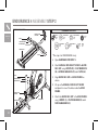
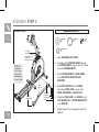
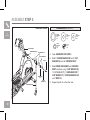
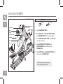
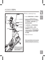
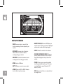
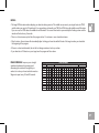
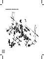
ENDURANCE 4 ENDURANCE 5 ELLIPTICAL OWNER’S MANUAL Read the ELLIPTICAL guide before using this owner’s manual. 2 ASSEMBLY WARNING There are several areas during the assembly process that special attention must be paid. It is very important to follow the assembly instructions correctly and to make sure all parts are firmly tightened. If the assembly instructions are not followed correctly, the elliptical could have frame parts that are not tightened and will seem loose and may cause irritating noises. To prevent damage to the elliptical, the assembly instructions must be reviewed and corrective actions should be taken. Before proceeding, find your elliptical’s serial number located on a white barcode sticker on the front stabilizer tube and enter it in the space provided below. SERIAL NUMBER LOCATION ENTER YOUR SERIAL NUMBER AND MODEL NAME IN THE BOXES BELOW: SERIAL NUMBER: EP MODEL NAME: Horizon ELLIPTICAL » Refer to the SERIAL NUMBER and MODEL NAME when calling for service. 3 SPEAKERS IPOD/MP3 PLAYER POCKET CONSOLE FAN CONSOLE ENDURANCE 4 SHOWN UPPER HANDLEBAR PULSE GRIPS TOUCH PAD PANEL AND DISPLAY WINDOWS CONSOLE MAST LOWER HANDLEBAR WATER BOTTLE HOLDER MANUAL INCLINE LIFT LEVER TOP CAP PIVOTING FOOT PADS CRANK GUIDE RAIL SET POWER CORD SOCKET STABILIZER TUBE MAIN FRAME PEDAL ARM REAR COVER 4 LOWER LINK ARM SPEAKERS CONSOLE FAN UPPER HANDLEBAR PULSE GRIPS IPOD/MP3 PLAYER POCKET CONSOLE ENDURANCE 5 TOUCH PAD PANEL AND DISPLAY WINDOWS SHOWN CONSOLE MAST WATER BOTTLE HOLDER TOP CAP CRANK LOWER HANDLEBAR POWER CORD SOCKET STABILIZER TUBE PIVOTING FOOT PADS GUIDE RAIL SET REAR COVER MAIN FRAME PEDAL ARM LOWER LINK ARM 5 TOOLS INCLUDED: FF 8 mm L-Wrench FF 5 mm L-Wrench / Screwdriver FF 13/15 mm Flat Wrench ALL MODELS PARTS INCLUDED: FF 1 Stabilizer Tube FF 1 Guide Rail Set FF 2 Pedal Arms FF 1 Manual Incline Set (Endurance 4 only) FF 2 Lower Handlebars FF 2 Upper Handlebars FF 2 Handlebar Caps FF 2 Lower Link Arms With Footpads FF 1 Top Cap (2 pieces) FF 1 Console Mast FF 1 Console Mast Boot FF 1 Console FF 2 Handlebar Caps FF 1 Water Bottle Holder FF 1 Rear Cover FF 1 Audio Adapter Cable FF 1 Power Cord FF 1 Hardware Kit 6 PRE ASSEMBLY UNPACKING Unpack the product where you will be using it. Place the elliptical carton on a level flat surface. It is recommended that you place a protective covering on your floor. Never open box when it is on its side. NOTE: During each assembly step, ensure that ALL nuts and bolts are in place and partially threaded in before completely tightening any ONE bolt. NOTE: A light application of grease may aid in the installation of hardware. Any grease, such as lithium bike grease is recommended. NOTE: It is recommended that two people work together for ease and efficiency while assembling an elliptical. NEED HELP? If you have questions or if there are any missing parts, contact Customer Tech Support. Contact information is located on the back panel of this manual. ASSEMBLY STEP 1 ENDURANCE 4 shown HARDWARE for step 1: BOLT (A) 30 mm Qty: 4 STABILIZER TUBE ARC WASHERS (C) SPRING WASHERS (B) BOLTS (A) SPRING WASHER (B) 15 mm Qty: 4 ARC WASHER (C) 17 mm Qty: 4 A Open hardware for step 1. B Attach the stabilizer tube to the main frame using 2 bolts (a), 2 spring washers (b) and 2 arc washers (C) on each side. ALL MODELS MAIN FRAME ENDURANCE 5 shown STABILIZER TUBE ARC WASHERS (C) SPRING WASHERS (B) BOLTS (A) MAIN FRAME 7 ENDURANCE 4 ASSEMBLY STEP 2 ENDURANCE 4 shown HARDWARE for step 2 MANUAL INCLINE LIFT LEVER ENDURANCE 4 ONLY FLAT WASHER (E) 16 mm Qty: 4 BOLT (D) 35 mm Qty: 4 NUTS (G) SPRING WASHER (F) 15 mm Qty: 4 NUT (G) Qty: 4 SPRING WASHERS (F) FLAT WASHERS (E) FLAT WASHER (H) 20 mm Qty: 4 SPRING WASHER (I) 18 mm Qty: 4 BOLT (J) 25 mm Qty: 4 GUIDE RAIL SET BOLTS (D) * This step is for ENDURANCE 4 only. A Open hardware for step 2. B Attach manual incline lift lever to guide rail set using 4 bolts (D), 4 flat washers (E), 4 spring washers (F) and 4 nuts (G). C Align guide rail set with main frame as BOLTS (J) SPRING WASHERS (I) shown. FLAT WASHERS (H) D Lift up on the manual incline lift lever and place it in one of the holes inside the main frame. E Attach the guide rail set to the main frame using 4 bolts (J), 4 flat washers (H) and 4 spring washers (I). MANUAL INCLINE LIFT LEVER MAIN FRAME GUIDE RAIL SET 8 ENDURANCE 5 ASSEMBLY STEP 2 HARDWARE for step 2: FLAT WASHER (D) 16 mm Qty: 4 SPRING WASHER (E) 15 mm Qty: 4 * This step is for ENDURANCE 5 models only. BOLT (F) 20 mm Qty: 4 BOLT (G) 35 mm Qty: 4 A Open hardware for step 2. ENDURANCE 5 ONLY B Attach the guide rail set to the FLAT WASHER (H) 20 mm Qty: 4 SPRING WASHER (I) 18 mm Qty: 4 NUT (J) Qty: 4 ENDURANCE 5 SHOWN main frame using 4 bolts (F), 4 spring washers (e) and 4 flat washers (D). C Attach the guide rail set to the INCLINE BRACKET using 4 bolts (G), 4 flat washers (H) and 4 spring washers (I) and 4 nuts (J). BOLTS (F) SPRING WASHERS (E) FLAT WASHERS (D) NOTE: You may need to pull the incline bracket out of the main frame in order to connect it to the guide rail set. INCLINE BRACKET NUTS (J) SPRING WASHERS (I) FLAT WASHERS (H) MAIN FRAME BOLTS (G) GUIDE RAIL SET 9 ASSEMBLY STEP 3 HARDWARE for step 3: ENDURANCE 5 shown ALL MODELS FLAT WASHER (K) 20 mm Qty: 2 WAVY WASHER (L) 22.5 mm Qty: 2 BOLT (M) 20 mm Qty: 2 SPRING WASHER (N) 15 mm Qty: 2 CONSOLE MAST CONSOLE CABLES PRE-INSTALLED BOLTS AND WASHERS A Open hardware for step 3. B Carefully pull the console cable through the console mast using the twist tie located inside the console mast. MAIN FRAME Note: Be careful not to pinch any wires while attaching the console mast. C Attach console mast to main frame using pre-installed bolts AND WASHERS. CRANK PEDAL ARM D Slide wavy washer (l) over crank followed by pedal arm as shown. Rest pedal arm wheel on guide rail. E Attach the pedal arm to the crank using 1 flat washer (k), 1 spring washer (N) and 1 bolt (M). F Repeat steps D–E on the opposite side of the elliptical. WAVY WASHER (L) FLAT WASHER (K) GUIDE RAIL PEDAL ARM WHEEL 10 SPRING WASHER (N) BOLT (M) ASSEMBLY STEP 4 HARDWARE for step 4: BOLT (O) 20 mm Qty: 2 SPRING WASHER (P) 15.4 mm Qty: 2 FLAT WASHER (Q) 20 mm Qty: 2 A Open hardware for step 4. B Slide the lower link arm into the pedal arm bracket. ALL MODELS C Attach the lower link arm to the pedal arm bracket using 1 flat washer (S), 1 spring washer (R) and 1 bolt (Q). D ENDURANCE 5 shown Repeat steps B–D on the opposite side of the elliptical. BOLT (Q) SPRING WASHER (R) FLAT WASHER (S) PEDAL ARM BRACKET LOWER LINK ARM 11 ASSEMBLY STEP 5 HARDWARE BAG 5 CONTENTS : ENDURANCE 5 SHOWN ALL MODELS CONSOLE MAST RUBBER WASHER (T) FLAT WASHERS (S) FLAT WASHERS (T) BOLT (V) RUBBER WASHER (R) 26 mm Qty: 2 FLAT WASHER (S) 25 mm Qty: 4 SPRING WASHER (U) 15 mm Qty: 2 BOLT (V) 20 mm Qty: 2 FLAT WASHER (T) 26 mm Qty: 4 A Open hardware for step 5. B Slide 1 rubber washer (R) and 1 flat washer (S) onto the console mast. C Slide lower handlebar onto console mast and attach using 1 flat washer (S), 1 FLAT WASHER (T), 1 handlebar cap, 1 flat washer (T), 1 spring washer (U) and 1 bolt (V). HANDLEBAR CAP SPRING WASHER (U) LOWER HANDLEBAR 12 D Repeat steps B–C on the other side. ASSEMBLY STEP 6 HARDWARE BAG 6 CONTENTS : ENDURANCE 5 SHOWN TEFLON WASHER (W) 28.4 mm Qty: 4 NUT (AA) NUT (AA) Qty: 2 B Align end of lower link arm with bracket on bottom of lower handlebar. ALL MODELS C Place teflon washers (W) on both sides of the lower link arm. While holding teflon washers (W) slide lower link arm into bottom end of lower handlebar. BOLT (Z) TEFLON WASHERS (W) BOLT (Z) 70 mm Qty: 2 Open hardware bag 6. SPRING WASHER (Y) LOWER LINK ARM SPRING WASHER (Y) 15 mm Qty: 2 A LOWER HANDLEBAR FLAT WASHER (X) FLAT WASHER (X) 17 mm Qty: 2 D Secure the joint with 1 flat washer (X), 1 spring washer (Y),1 bolt (Z) and secure with 1 nut (AA). E Repeat steps B–D on the opposite side of the elliptical. 13 ASSEMBLY STEP 7 HARDWARE BAG 7 CONTENTS : ENDURANCE 5 SHOWN ALL SCREW (BB) 12 mm Qty: 3 MODELS SCREW (CC) 15 mm Qty: 2 SCREWS (BB) CONSOLE MAST TOP CAP REAR COVER WATER BOTTLE HOLDER A Open hardware bag 7. B Slide top cap and top cap rear cover over console mast and snap into place. CONSOLE MAST BOOT SCREW (BB) C Insert console mast boot over top cap TOP CAP SCREWS (CC) and snap into place. REAR CAP D Slide water bottle holder over console mast and attach using 3 screws (BB). E Slide rear cap over rear stabilizer and attach using 2 screws (CC). Note: Be careful not to pinch any wires while tightening screws. 14 ASSEMBLY STEP 8 ENDURANCE 5 SHOWN HANDLEBAR CAP NOTE: There is no hardware bag for this step. A CONSOLE CABLES B CONSOLE UPPER HANDLEBAR PRE-INSTALLED BOLTS PRE-INSTALLED SET SCREWS Attach the console cables to the console. Carefully tuck the console cables into the console mast before attaching the console. Attach console to console mast using 4 PRE-INSTALLED bolts. ALL MODELS C The HANDLEBAR to the upper handlebar. D Slide upper handlebar onto lower handlebar making sure handlebars are joined together completely. Secure upper handlebar to lower handlebar using pre-attached set screws. E Repeat step E on other side. CONSOLE MAST LOWER HANDLEBAR Make sure upper handlebars are as far down as possible. Handlebars can be damaged If not secured correctly. Note: Be careful not to pinch any wires while attaching the console or handlebars. 15 ENDURANCE 4 SHOWN ASSEMBLY COMPLETE! ENDURANCE 4 Max. User Weight: 136 kg / 300 lbs Product Weight: 84 kg / 185 lbs Overall Dimension: 190 x 62 x 168 cm / 75” x 24” x 66” 16 ENDURANCE 5 SHOWN ENDURANCE 5 Max. User Weight: 148 kg / 325 lbs Product Weight: 87 kg / 192 lbs Overall Dimension: 190 x 62 x 168 cm / 75” x 24” x 66” 17 18 ELLIPTICAL OPERATION This section explains how to use your elliptical’s console and programming. The BASIC OPERATION section in the elliptical guide has instructions for the following: • LOCATION OF THE Elliptical • POWER/GROUNDING INSTRUCTIONS • FOOT POSITIONING • MOVING the elliptical • LEVELING the elliptical • POWER/MANUAL INCLINE OPERATION • Using the HEART RATE function 19 K ENDURANCE 4 O SHOWN O L ENDURANCE 4 I I A Q EnergySaver ENERGIESPARMODUS B INTERVAL WORKOUTS WEIGHT LOSS WORKOUTS INTERVALLPROGRAMME SPEED INTERVALS GESCHWINDIGKEITSINTERVALL HR INTERVALS HR INTERVALL PEAK INTERVALS SPITZENINTERVALL GEWICHTSREDUZIERUNGSPROGRAMME CARDIO BURN AUSDAUER MUSCLE TONER STRENGTH BUILDER KRÄFTIGUNG PERFORMANCE WORKOUTS LEISTUNGSPROGRAMME PEAK DESCENT GIPFELABSTIEG NATURE TRAIL WANDERN CONSTANT WATTS WATTGESTEUERT MOUNTAIN CLIMB HRC HERZFREQUENZGESTEUERT M BERGBESTEIGEN P N C LEVEL WIDERS TAND GOAL CENTER FAN VENTILATOR J CHANGE DISPLAY ANZEIGENWECHSEL START PAUSE 20 STOP ENTER EINGABE LEVEL G TAND WIDERS J HOLD TO RESET FÜR NULLSTELLUNG GEDRÜCKT HALTEN D H E F ENDURANCE 4 CONSOLE OPERATION Note: There is a thin protective sheet of clear plastic on the overlay of the console that should be removed before use. A) LCD display window: time, distance, calories, watts, RPM, speed, resistance level, heart rate, and fan. B) Programs: press to select which workout. C) Fan button: with each press of the button, the fan cycles from low to medium to high and off. D) Change display: press to change display feedback during workout. E) Start: press to begin exercising, start your workout, or resume exercising after pause. F) Stop: press to pause/end your workout. Hold for 3 seconds to reset the console. G) Goal center: press to set or view your goal. See page 32 for more information. H) Enter: used to confirm a selection. I) Quick keys: used to reach desired resistance level more quickly. J) Level : used to adjust resistance level. K) Audio in jack: plug your CD / MP3 player into the console using the included audio adaptor cable. L) MP3 player pocket: used to store your MP3 player. M) Reading rack: holds reading material. N) Fan: personal workout fan. O) Speakers: music plays through speakers when your CD / MP3 player is connected to the console. P) Volume buttons: adjust speaker volume up or down. Q) Energy Saver light: Indicates if machine is in Energy Saver mode. ENDURANCE 4 SHOWN Manual Incline Operation The Endurance 4 has an adjustable incline feature to add variety to your workouts. To adjust the incline up or down, stand on the side of the elliptical and place your hand firmly on the top of the shroud. With your other hand, grab the manual incline lift lever handle, pulling back and guiding it up or down. Ensure the pin is engaged in the slot at the preferred incline level. 21 O ENDURANCE 5 S SHOWN S P ENDURANCE 5 M N A B T EnergySaver ENERGIESPARMODUS INTERVAL WORKOUTS INTERVALLPROGRAMME SPEED HR PEAK INTERVALS INTERVALS INTERVALS GESCHWINDIGKEITSINTERVALL HR INTERVALL SPITZENINTERVALL WEIGHT LOSS WORKOUTS GEWICHTSREDUZIERUNGSPROGRAMME CARDIO BURN AUSDAUER MUSCLE TONER STRAFFUNG Q STRENGTH BUILDER KRÄFTIGUNG PERFORMANCE WORKOUTS LEISTUNGSPROGRAMME PEAK DESCENT GIPFELABSTIEG NATURE TRAIL WANDERN CONSTANT WATTS WATTGESTEUERT MOUNTAIN CLIMB BERGBESTEIGEN HRC C CUSTOM HERZFREQUENZGESTEUERT BENUTZER 1 2 H R D I INCLINE STEIGUNG K FAN GOAL CENTER VENTILATOR CHANGE DISPLAY ANZEIGENWECHSEL START PAUSE 22 STOP ENTER EINGABE LEVEL WIDERSTAND L HOLD TO RESET FÜR NULLSTELLUNG GEDRÜCKT HALTEN E J F G ENDURANCE 5 CONSOLE OPERATION Note: There is a thin protective sheet of clear plastic on the overlay of the console that should be removed before use. A) LCD display window: time, distance, calories, watts, RPM, incline, speed, resistance level, heart rate, and fan. B) Programs: press to select which workout. C) Custom 1 & 2 Keys: press to select custom 1 or custom 2 program. D) Fan button: with each press of the button, the fan cycles from low to medium to high and off. E) Change display: press to change display feedback during workout. F) Start: press to begin exercising, start your workout, or resume exercising after pause. G) Stop: press to pause/end your workout. Hold for 3 seconds to reset the console. H) Volume buttons: adjust speaker volume up or down. I) Goal center: press to set or view your goal. See page 32 for more information. J) Enter: used to confirm a selection. K) Incline : used to adjust incline level. L) LEVEL : used to adjust resistance level. M) Incline quick keys: used to reach desired incline level more quickly. N) Level quick keys: used to reach desired resistance level more quickly. O) Audio in jack: plug your CD / MP3 player into the console using the included audio adaptor cable. P) MP3 player pocket: used to store your MP3 player. Q) Reading rack: holds reading material. R) Fan: personal workout fan. S) Speakers: music plays through speakers when your CD / MP3 player is connected to the console. T) Energy Saver light: Indicates if machine is in Energy Saver mode. ENDURANCE 5 SHOWN 23 Display windows • TIME: Shown as minutes : seconds. View the time remaining or the time elapsed in your workout. • HEART RATE (HR): Shown as BPM (beats per minute). Used to monitor your heart rate (displayed when contact is made with both pulse grips). • DISTANCE: Shown as miles or kilometres. Indicates distance traveled or distance remaining during your workout. • Level: Shows the current level of resistance. • CALORIES: Total calories burned or calories remaining left to burn during your workout. • RPM: Rotations Per Minute. • Watts: Displays current user power output. 24 • SPEED: Shown as MPH or KMPH. Indicates how fast the foot pads are moving. • INCLINE (ENDURANCE 5 ONLY): Shown as percent. Indicates the incline level of the power ramp. Will be displayed in the top left corner of window. • TRACK: Follows progress around a simulated track. Segments light up with every 12.5 meters completed. One lap around the track is 400 meters (1/4 mile). • Fan: Indicates when the fan is on and what level of strength it is on. GETTING STARTED 1) Check to make sure no objects are nearby that will hinder the movement of the elliptical. 2) Plug in the power cord and turn the elliptical ON. (Switch is located at the bottom-front of the elliptical.) NOTE: Some ellipticals may not have a power switch and will turn on when power is supplied. 3) Select user 1, user 2, or guest using press enter. 4) Select WEIGHT using and and press enter. A) Quick start up Simply press the START key to begin working out. The time will count up from 0:00, the resistance level will default to level 1. Endurance 5 only: Incline will default to 0%. OR... CHANGING YOUR PROGRAM MID-WORKOUT Anytime during your workout (Except HR INTERVALS & HRC), press program button to select a new program. Press ENTER and a new workout will begin at the first segment. All workout statistics will roll over. A new workout will begin at the first segment and all workout statistics will roll over. NOTE: If you accidentally press a program button during a workout, do not press any other buttons and the current workout will not change. B) SELECT PROGRAM 1) Press a program button to select a workout. 2) Set workout time using and press ENTER. 3) Set workout level using and press ENTER. 4) Press START to begin workout. NOTE: You can also adjust the level during your workout. C) FINISHING YOUR WORKOUT To reset the console Hold stop key for 3 seconds. Clear current selection To clear the current program selection or screen, hold the stop button for 3 seconds. When your workout is complete, the monitor display will run ‘FINSHED’ and beep. Your workout information will stay displayed on the console for 30 seconds and then reset. 25 PROGRAM INFORMATION Manual: Adjust your resistance level manually during your workout. INTERVAL WORKOUTS SPEED intervals: Improves your strength, speed and endurance by increasing and decreasing the resistance throughout your workout to involve your heart and other muscles. Segments repeat every 30 and 90 seconds. HR INTERVALS: Automatically adjusts work and rest resistance levels within your desired heart rate. Perfect for providing an intense workout with recovery bursts. Time-based goal. 1) Set WORK interval time using ENTER. and press 2) Set WORK interval target heart rate using and press ENTER. 3) Set REST interval time using and press ENTER. 4) Set REST interval target heart rate using and press ENTER. 26 5) Set TOTAL WORKOUT TIME using press START to begin. and SPEED INTERVALS Segment Warm Up Program Segments - Repeat Cool Down Seconds 60 60 60 60 30 90 90 30 30 90 30 90 90 30 30 90 60 60 60 60 Level 1 2 3 4 5 6 7 8 9 10 11 12 13 14 15 16 17 18 19 20 1 1 1 1 1 3 1 1 3 3 1 3 1 1 3 3 1 1 1 1 1 2 1 1 1 2 3 1 1 3 3 1 3 1 1 3 3 1 2 1 1 1 3 1 1 1 2 4 2 2 4 4 2 4 2 2 4 4 2 2 1 1 1 4 1 1 1 3 4 2 2 4 4 2 4 2 2 4 4 2 3 1 1 1 5 1 2 3 3 5 3 3 5 5 3 5 3 3 5 5 3 3 3 2 1 6 1 2 3 4 5 3 3 5 5 3 5 3 3 5 5 3 4 3 2 1 7 1 2 3 4 6 4 4 6 6 4 6 4 4 6 6 4 4 3 2 1 8 1 2 3 5 6 4 4 6 6 4 6 4 4 6 6 4 5 3 2 1 9 2 2 3 5 7 5 5 7 7 5 7 5 5 7 7 5 5 3 2 2 10 2 2 4 6 7 5 5 7 7 5 7 5 5 7 7 5 6 4 2 2 Segments Warm Up Work Interval Rest Interval Time 4:00 The work interval and rest interval segment times are preset by the user and are repeated until the cool down Resistance 1 or user selects THR set by user for the work and rest intervals Cool Down 2:00 min 2:00 min 1/2 current resistance 1 NOTES: • The large LCD dot matrix window displays your heart rate during exercise. The middle row represents your target heart rate (THR) and the other rows equal +/-5 heart beats. If you are working out beneath your THR, the LCDs below the middle row will illuminate. If you are over, the LCDs above the middle row will illuminate. Your current heart rate is represented by the flashing column and the window will refresh every 5 seconds. • There is a 4-minute warm-up built into this program at level 1 resistance or user selected resistance. • After 4 minutes, the resistance will automatically adjust to bring your heart rate within 5 beats of the target number you selected at the beginning of the program. • If there is no heart rate detected, the unit will not change resistance levels up or down. • If your heart rate is 25 beats over your target zone the program will slow down. PEAK intervals: Improves your strength, speed and endurance by increasing and decreasing the resistance throughout your workout to involve your heart and other muscles. Segments repeat every 30 and 60 seconds. Segments Seconds Level 1 2 3 4 5 6 7 8 9 10 PEAK INTERVALS Warm Up Program Segments - Repeat Cool Down 60 60 60 60 30 60 60 30 30 60 30 60 60 30 30 60 60 60 60 60 1 2 3 4 5 6 7 8 9 10 11 12 13 14 15 16 17 18 19 20 1 1 1 1 3 1 1 3 3 1 3 1 1 3 3 1 1 1 1 1 1 1 1 2 3 1 1 3 3 1 3 1 1 3 3 1 2 1 1 1 1 1 1 2 4 2 2 4 4 2 4 2 2 4 4 2 2 1 1 1 1 1 1 3 4 2 2 4 4 2 4 2 2 4 4 2 3 1 1 1 1 2 3 3 5 3 3 5 5 3 5 3 3 5 5 3 3 3 2 1 1 2 3 4 5 3 3 5 5 3 5 3 3 5 5 3 4 3 2 1 1 2 3 4 6 4 4 6 6 4 6 4 4 6 6 4 4 3 2 1 1 2 3 5 6 4 4 6 6 4 6 4 4 6 6 4 5 3 2 1 2 2 3 5 7 5 5 7 7 5 7 5 5 7 7 5 5 3 2 2 2 2 4 6 7 5 5 7 7 5 7 5 5 7 7 5 6 4 2 2 27 PROGRAM information WEIGHT LOSS WORKOUTS CARDIO BURN: Promotes weight loss by increasing and decreasing the resistance, while keeping you in your fat burning zone. Segments repeat every 60 seconds. MUSCLE TONER: Tones muscles by adjusting resistance gradually while keeping you in your fat burning zone. Segments change every 30 seconds. Time based goal with 10 difficulty levels to choose from. STRENGTH BUILDER: Time segments vary from 30 to 90 seconds long to challenge your stamina and strength. Time based goal with 10 difficulty levels to choose from. 28 CARDIO BURN 60 Second Program Segments - Repeat 6 7 8 9 10 11 12 13 14 15 3 4 4 5 5 5 5 4 4 3 4 5 5 6 6 6 6 5 5 4 5 6 6 7 7 7 7 6 6 5 6 7 7 8 8 8 8 7 7 6 7 8 8 9 9 9 9 8 8 7 8 9 9 10 10 10 10 9 9 8 9 10 10 11 11 11 11 10 10 9 10 11 11 12 12 12 12 11 11 10 11 12 12 13 13 13 13 12 12 11 12 13 13 14 14 14 14 13 13 12 13 14 14 15 15 15 15 14 14 13 14 15 15 16 16 16 16 15 15 14 15 16 16 17 17 17 17 16 16 15 16 17 17 18 18 18 18 17 17 16 17 18 18 19 19 19 19 18 18 17 18 19 19 20 20 20 20 19 19 18 16 3 4 5 6 7 8 9 10 11 12 13 14 15 16 17 18 Cool Down 17 18 19 20 3 2 3 1 3 2 2 1 4 2 2 1 5 2 2 1 6 5 3 2 7 5 3 2 8 5 3 2 9 5 3 2 10 5 4 3 11 8 4 3 12 10 6 3 13 10 6 3 14 13 9 5 15 13 9 5 16 13 9 5 17 13 9 5 MUSCLE TONER Program Segments - Repeat 30 30 30 30 30 30 30 30 7 8 9 10 11 12 13 14 3 3 2 2 3 3 2 2 3 4 2 3 3 4 2 3 4 4 3 3 4 4 3 3 4 5 3 4 4 5 3 4 5 5 4 4 5 5 4 4 5 6 4 5 5 6 4 5 7 7 6 6 7 7 6 6 8 8 7 7 8 8 7 7 9 10 8 8 9 11 8 8 11 11 9 9 12 12 9 9 30 15 3 3 4 4 5 5 7 8 11 13 30 16 3 4 4 5 5 6 7 8 11 13 Cool Down 60 60 60 60 17 18 19 20 2 1 1 1 3 2 1 1 3 2 2 1 3 2 2 2 3 3 3 3 4 3 3 3 4 4 4 4 5 4 4 4 5 5 4 4 6 5 5 4 STRENGTH BUILDER Segment Warm Up Program Segments - Repeat Seconds 60 60 60 60 30 60 90 60 90 45 60 45 90 90 Level 1 2 3 4 5 6 7 8 9 10 11 12 13 14 1 1 1 1 2 2 2 2 1 2 2 1 2 2 1 2 1 1 1 2 3 2 3 2 2 3 2 2 3 2 3 1 1 1 2 4 3 4 2 3 4 2 3 4 2 4 1 1 1 2 5 4 5 3 4 5 3 4 5 3 5 1 2 2 2 5 5 5 4 5 5 4 5 5 4 6 1 2 2 3 6 5 6 5 5 6 5 5 6 5 7 1 2 2 3 7 6 7 5 6 7 5 6 7 5 8 1 1 1 2 9 8 9 8 8 9 8 8 9 8 9 2 2 2 3 11 10 11 9 10 11 9 10 11 9 10 2 3 4 5 12 12 12 11 12 12 11 12 12 11 30 15 2 2 3 4 5 5 6 8 10 12 30 16 2 3 4 5 5 6 7 9 11 12 Cool Down 60 60 60 60 17 18 19 20 2 1 1 1 2 1 1 1 2 1 1 1 2 1 1 1 2 2 2 1 3 2 2 1 3 2 2 1 2 1 1 1 2 1 1 1 3 2 2 1 Segment Warm Up Level 1 2 3 1 1 2 2 2 1 2 2 3 1 2 2 4 1 2 2 5 2 3 5 6 2 3 5 7 2 3 5 8 2 3 5 9 3 4 5 10 3 4 8 11 3 6 10 12 3 6 10 13 5 9 13 14 5 9 13 15 5 9 13 16 5 9 13 4 3 3 4 5 6 7 8 9 10 11 12 13 14 15 16 17 5 3 4 5 6 7 8 9 10 11 12 13 14 15 16 17 18 Segment Warm Up Seconds 60 60 60 60 30 30 Level 1 2 3 4 5 6 1 1 1 1 2 2 2 2 1 1 2 3 2 3 3 1 2 2 3 3 3 4 2 2 2 3 3 4 5 3 3 3 3 4 4 6 3 3 3 4 4 5 7 4 4 4 4 6 6 8 4 4 4 5 7 7 9 4 4 5 5 8 8 10 4 5 5 6 9 11 PROGRAM information PEAK DESCENT Segments ELEVATION Level 1 RESISTANCE ELEVATION Level 2 RESISTANCE PERFORMANCE WORKOUTS ELEVATION Level 3 RESISTANCE ELEVATION Level 4 RESISTANCE ELEVATION Peak descent: Promotes gradual changes of ascent and descent. Helps tone muscles and build cardiovascular fitness. Time based goal with 10 difficulty levels to choose from. For Endurance 4, please ignore elevation line. Level 5 RESISTANCE ELEVATION Level 6 RESISTANCE ELEVATION Level 7 RESISTANCE ELEVATION Level 8 RESISTANCE ELEVATION Level 9 RESISTANCE ELEVATION Level 10 RESISTANCE Nature trail: Simulates the ascent and descent of trail walking. Helps tone muscles and build cardiovascular fitness. Resistance changes. Time based goal with 10 difficulty levels to choose from. MOUNTAIN CLIMB: Experience changing resistance levels simulating an outdoor hiking experience. Helps tone muscles and build cardiovascular fitness. Time based goal with 10 difficulty levels to choose from. 1 0 1 0 1 0 1 0 1 10 2 10 2 10 2 10 2 20 3 20 3 Warm Up 2 3 4 10 10 20 2 2 3 10 10 20 2 2 3 10 10 30 2 2 4 10 10 30 2 2 5 30 30 40 5 5 6 30 30 50 5 5 7 30 30 50 5 5 8 30 30 60 5 5 9 30 30 70 5 5 10 50 50 80 8 8 11 Segment Warm Up Level 1 2 3 1 1 1 1 2 1 1 2 3 1 1 2 4 1 1 3 5 2 2 2 6 2 2 3 7 3 3 3 8 3 3 3 9 3 3 3 10 3 3 3 4 1 2 2 3 2 3 3 3 3 3 5 20 3 30 4 30 5 40 6 50 7 50 8 60 9 70 10 80 11 80 12 5 3 4 4 5 6 6 7 8 8 9 60 Second Program Segments - Repeat 6 7 8 9 10 11 12 13 14 15 20 30 30 30 30 30 30 30 30 20 3 4 4 5 5 5 5 4 4 3 30 30 30 40 40 40 40 40 40 30 4 5 5 6 6 6 6 5 5 4 30 40 40 50 50 50 50 50 50 30 5 6 6 7 7 7 7 6 6 5 40 50 50 50 50 50 50 50 50 40 6 7 7 8 8 8 8 7 7 6 50 50 50 60 60 60 60 60 60 50 7 8 8 9 9 9 9 8 8 7 50 60 60 70 70 70 70 70 70 50 8 9 9 10 10 10 10 9 9 8 60 70 70 80 80 80 80 80 80 60 9 10 10 11 11 11 11 10 10 9 70 80 80 80 80 80 80 80 80 70 10 11 11 12 12 12 12 11 11 10 80 80 80 90 90 90 90 90 90 80 11 12 12 13 13 13 13 12 12 11 80 90 90 90 90 90 90 90 90 80 12 13 13 14 14 14 14 13 13 12 16 20 3 30 4 30 5 40 6 50 7 50 8 60 9 70 10 80 11 80 12 Cool Down 17 18 19 20 20 10 10 0 3 2 2 1 20 10 10 0 3 2 2 1 30 10 10 0 4 2 2 1 30 10 10 0 5 2 2 1 40 30 30 10 6 5 5 2 50 30 30 10 7 5 5 2 50 30 30 10 8 5 5 2 60 30 30 10 9 5 5 2 70 30 30 20 10 5 5 3 80 50 50 20 11 8 8 3 NATURE TRAIL 60 Second Program Segments - Repeat Cool Down 6 7 8 9 10 11 12 13 14 15 16 17 18 19 20 3 3 3 4 4 4 4 3 3 3 3 2 2 1 1 4 4 4 5 5 5 5 4 4 4 4 2 2 1 1 4 6 6 6 6 6 6 6 6 4 4 2 2 1 1 5 6 6 7 8 8 7 6 6 5 5 2 2 1 1 6 7 7 8 8 8 8 7 7 6 6 3 3 2 2 6 8 8 8 9 9 8 8 8 6 6 3 3 2 2 7 8 8 9 9 9 9 8 8 7 7 3 3 3 3 8 9 9 9 10 10 9 9 9 8 8 3 3 3 3 8 9 9 10 11 12 10 9 9 8 8 3 3 3 3 9 10 10 11 12 12 12 10 10 9 9 3 3 3 3 MOUNTAIN CLIMB Segment Warm Up Program Segments - Repeat Seconds 60 60 60 60 30 60 60 30 30 60 30 60 60 30 Level 1 2 3 4 5 6 7 8 9 10 11 12 13 14 1 1 1 2 3 5 5 6 6 6 6 6 6 6 7 2 1 1 2 4 5 6 6 6 6 6 7 7 7 8 3 1 1 1 1 6 6 6 7 8 8 8 7 8 8 4 1 1 1 1 6 6 6 6 7 8 8 9 9 9 5 1 1 1 2 5 6 6 6 7 8 9 9 9 9 6 2 2 2 3 5 6 6 6 7 8 9 9 10 10 7 2 3 3 4 6 6 6 6 7 7 8 9 9 10 8 2 3 4 4 6 6 6 7 7 8 8 9 9 10 9 2 4 4 5 7 7 7 8 8 9 9 9 10 11 10 3 4 5 6 7 7 8 8 9 9 9 10 11 11 30 15 7 8 7 9 10 10 11 11 12 12 60 16 7 8 8 9 10 10 11 11 12 12 Cool Down 60 60 60 60 17 18 19 20 3 2 1 1 4 2 1 1 1 1 1 1 1 1 1 1 1 2 2 1 2 1 1 1 2 2 1 1 3 2 1 1 3 2 1 1 4 2 1 1 29 PROGRAM information CONSTANT WATTS: This workout automatically adjusts the resistance to keep you within a set Watts range and maintains your desired level of exercise intensity. 1) Press CONSTANT WATTS program key and press ENTER to confirm . 2) Set time using and press ENTER . 3) Select desired watts using and press ENTER . 4) Press START to begin. HRC: Simulate the intensity of your favorite sport as the program resistance automatically adjusts to maintain a set Target Heart Rate range. 1) Press HRC program key and press ENTER to confirm . 2) Select TIME using and press ENTER . 3) The HEART RATE will flash showing the default target heart rate of 80 beats per minute. Select your target heart rate using and press ENTER. 4) Press START to begin. NOTES: • The large LCD dot matrix window displays your heart rate during exercise. The middle row represents your target heart rate (THR) and the other rows equal +/-5 heart beats. If you are working out beneath your THR, the LCDs below the middle row will illuminate. If you are over, the LCDs above the middle row will illuminate. Your current heart rate is represented by the flashing column and the window will refresh every 5 seconds. • There is a 4-minute warm-up built into this program at level 1 resistance. • After 4 minutes, the resistance will automatically adjust to bring your heart rate within 5 beats of the target number you selected at the beginning of the program. • If there is no heart rate detected, the unit will not change resistance levels up or down. • If your heart rate is 25 beats over your target zone the program will slow down. 30 Using custom programs (ENDURANCE 5 only) 1) Press the CUSTOM 1 or 2 key to select a custom program. Press ENTER to confirm. 2) Set the workout time using and press ENTER. to set the resistance level for each segment. Press ENTER to confirm the resistance setting for each segment of 3) Use the workout. 4) Use to set the incline for each segment. Press ENTER to confirm the incline setting for each segment of the workout. 5) Press START to begin workout. Using your CD / MP3 player 1) Connect the included audio adaptor cable to the audio in jack on the top right of the console and the headphone jack on your cd / mp3 player. 2) Use your cd / mp3 player buttons to adjust song settings. 3) Remove the audio adaptor cable when not in use. 31 GOAL CENTER™ Research shows that those who create and track their fitness goals, on average, achieve greater success than those who do not. Because your new elliptical is equipped with Horizon’s exclusive GOAL CENTER Performance Tracker, you’ve taken an important step towards achieving your fitness goals. GOAL CENTER is innovative new software, integrated into your console, that will allow you to track your fitness goals over time, without the need for paper journals or logs. GOAL CENTER™ SETUP 1) Select USER 1 or USER 2. 2) Press and hold the GOAL CENTER button for approximately five seconds. 3) Select a time, distance or calorie goal using . Press ENTER. 4) Use to select a goal value. Press ENTER. 5) Use to select the NUMBER OF DAYS to complete the goal. 6) Press ENTER again to exit GOAL CENTER setup. NOTE: These steps can also be used to erase an existing goal and set a new one. HOW TO SAVE WORKOUT DATA TO GOAL CENTER At the end of your workout, the console will save your workout data towards your goal. VIEWING GOAL PROGRESS At any time during or before a workout, you can view your progress towards your goal by pressing the GOAL CENTER button. Use to select user 1 or user 2 and press ENTER. The console will scroll the remaining time, distance or calories, depending on the goal you set previously and will also scroll the time remaining to achieve your goal. 32 ENERGY SAVER (standby mode) This elliptical has an energy saver mode. The display will automatically enter standby mode (energy saver mode) after 15 minutes of inactivity. Almost all power for the elliptical will be off except for some circuits that are needed to detect a key press or RPM detection, indicating the console should “wake up”. 33 ENDURANCE 4 EXPLODED VIEW 8 Z15 Z02 Z13 G12 Z13 Z14 AN1 10 Z14 Q11 Z16 Z02 Q15x6 Z15 Z02 Z13 Z18 Z20 Q03 Z11 Z17 J04 J06 Q20x3 J06 J05 Q13 J03x2 Z18 12 2 B23x4 P02 B12x2 P05 R06 Q16x4 Z15 P03 B20 M44 B19 B18 Z02X4 Z11 X4 Z10X4 5 D13x2 R14 R09 R08 R07 B16x4 19 16 Z13 Z02 L05 L04L03 L02L06X2 Z23 21 6 Z23 Z23 Q17x12 Q16x6 C06 AJ1 Z12 P12 N24x4 Q04 P20 R09 R14 R17 R07 R17 R08 R04 M42x4 M40 M41 Z01x4 Z02x4 Z03x4 Z22x2 15 Q20 34 J04 Z09X4 20 Q20 Q20J06 J05 J06 Z15 Z02 Z13 Z07x4 Z08x4 Z06x4 1 P04 7 3 AD3 F10 D11 D12 Z14 Z13 P06 Q16x6 4 Z20 Z14 M43 D14 D10 D12 D11 AD3 F10 Q14x2 Q24 14 9 L06X2 L02 L03 L04 L05 P07X3 11 AJ1 Q13 Z12 J03x2 Z13 Z02 Z15 Z11 Z18 Z18 D10 13 Z17 Z02 Z16 G12 Z13 Z02 Z15 ENDURANCE 4 parts list NO. DESCRIPTION NO. DESCRIPTION 1 FRAME SET;REAR;EP565B-SBOM; B16 SCREW;SH;M10X1.5PX15L;HS;BZN;BP 2 CONSOLE MAST SET;SA;S-EP566B; B17 WASHER;FLT;Φ12.0XΦ23.0X2.5T; 3 GUIDE RAIL SET;SA;R;S-EP566B; B18 STOPPER BLOCK;CAM;GM30 4 GUIDE RAIL SET;SA;L;S-EP566B; B19 SCREW;BH;M8X1.25PX20L;HS;BP 5 CONNECTING SET;SA;EP565B-SBOM; B20 FOAM;SINGLE;45X20X4T 6 PEDAL ARM SET;SA;L;S-EP566B; C06 BOTTLE HOLDER;ABS;DG;75140;EP565B-2KM; 7 PEDAL ARM SET;SA;R;S-EP566B; D10 SCREW;BH;M8X1.25PX20L;HS;BP 8 ARM REST SET;SA;LU;S-EP566B; D11 WASHER;FLT;Φ8.2XΦ20.0X1.5T;BZN; 9 ARM REST SET;SA;RU;S-EP566B; D13 CABLE TIE;NYLON;BLACK;160L 10 ARM REST SET;SA;LD;S-EP566B; D14 RIBBON(WHITE);760L 11 ARM REST SET;SA;RD;S-EP566B; F10 FOOT PAD;ADJUST;RUBBER;W3/8-16UNC;FMW38A 12 LINK ARM;L;EP565B-SBOM G12 COVER;HAND ARM;NYLON+30%;B;EP217 13 LINK ARM;R;EP565B-SBOM; J03 SCREW;FH;M5X0.8PX12L;PH;BAN;BP 14 STABILIZER SET;SA;S-EP566B; J04 SCREW;SH;M10X1.5PX60L;22#;HS;G12.9;BAN; 15 16 COVER SET;SA;B;EP565-SBOM; SIDE COVER SET;L;EP565B-SBOM; J05 NUT;M10X1.5P;G10;BAN; J06 WASHER;FLT;Φ10.2XΦ15.0X1.5T;BZN; 19 DRIVE AXLE SET;SA;EP543-1US;S; L02 BUSHING;MOVE WHEEL;BLACK;EP188 20 SIDE COVER SET; R; EP565B-SBOM ; L03 WHEEL SET;RB106 21 SHIELD SET;MID STABILIZER ;EP565B-SBOM;- L04 WASHER;FLT;Φ8.2XΦ25.0X1.5T;BZN; AD3 ADJUSTMENT SET; EP565B-SBOM ; GR; L05 SCREW;BH;M8X1.25PX15L;HS;BZN; AJ1 CR ANK SET;WELDING; EP543-1US; L06 SCREW;BH;Φ4X15L;SM;PH;BZN;POT AN1 CONSOLE SET; SA; EP565B-2KM ; M40 MOTOR ECB AZ1 HARDWARE SET; EP565B-2KM ; M41 STEEL ROPE;ECB; 160L;L1+L2= 65 B12 CLIP; STANDARD; FE; ZNC M42 SCREW;BH;Φ4X12L;TC;PH;BAN;POT B16 SCREW;SH;M10X1.5PX15L;HS;BZN;BP M43 CABLE TIE;NYLON;300L;WHITE 35 NO. 36 DESCRIPTION NO. DESCRIPTION M44 SCREW;BH;Φ4X10L;TC;PH;BAN;POT Z01 SCREW;BH;M8X1.25PX30L;HS; P02 WIRE;CONSOLE;DOWN1200MM(CKM254301-8P+SM- Z02 WASHER;SPL;Φ8.2XΦ15.4X2.0T; P03 SENSOR WIRE Z03 WASHER;ARC;Φ8.4XΦ17.0X1.0T; P04 POWER WIRE;DC;600MM(DC+CKM 25430101-2P) Z06 WASHER;FLT;Φ10.2XΦ20.0X1.5T;BZN; P05 SCREW;BH;Φ3X10L;TC;PH;BOX;POT Z07 SCREW;SH;M10X1.5PX20L;HS;BZN; P06 TIE STRAP ADHESIVE; NYLON66;HC-101;W Z08 WASHER;SPL;Φ10.2XΦ18.4X2.5T;BAN; P07 CABLE TIE;NYLON;BLACK;160L Z09 SCREW;BH;M8X1.25PX35L-20L;HS;P-T P12 ADAPTOR;USA;100-240V 12V/2A ;HZ Z10 WASHER;FLT;Φ8.2XΦ16.0X2.0T;BZN; Q03 PLASTIC COVER;U;ABS;BS;877C;EP565B-2KM; Z11 NUT;NLK;M8X1.25P;BZN; Q04 PLASTIC COVER;ABS;BS;877C;EP565B-2KM; Z12 WASHER;WW;Φ17.2XΦ22.5X0.5T;65MN Q11 BOOT;CONSOLE;PVC;EP520-1US Z13 WASHER;FLT;Φ8.2XΦ20.0X1.5T;BZN; Q13 CRANK COVER;ABS;877C;SILVERP565B-2KM; Z14 WASHER;FLT;Φ16.0XΦ25.0X1.5T; Q14 SCREW;BH;Φ4X15L;TC;PH;G8.8;NKL;POT Z15 SCREW;BH;M8X1.25PX20L;HS;BP Q15 BRACKET SIDE COVER Z16 SCREW;BH;M8X1.25PX70L-12L;HS;BP;P-T Q16 SCREW;BH;Φ4X15L;TC;PH;BAN;POT Z17 WASHER;FLT;Φ8.4XΦ17.0X1.0T;BZN; Q17 CLIP; STANDARD; FE; ZNC Z18 WASHER;FLT;Φ15.9XΦ28.4X1.0T;TFN; Q20 SCREW;BH;(Φ10.4);Φ4X15L;SM;PH;BAN;POT Z20 RING;RUBBER;Φ26.2XΦ16.20X11.50 Q24 PL ASTIC COVER; PVC; 877C; Z22 SCREW;BH;Φ4X15L;TC;PH;BAN;POT R04 FLYWHEEL;8.0KG EP537-1US; Z23 SCREW;BH;M4X0.7PX12L;CT;PH;BAN; R06 BELT; POLY-V; RUBBER;490 J10; R01 AXLE,TR ANSIMISSION ;42CRMO; R07 SCREW; EB;1/4-20UNCX55L;Φ12; BZN ; R02 EENSOR MAGENT;Φ15X7T;1900GAUSS R08 NUT; HX; M12X1.75PX10L; G8; SS41 R03 PULLEY; POLY-V; NYLON ;Φ360 J10; R09 NUT; NLK;1/4'-20UNC; BZN ; R05 BEARING; BALL; 6005ZZ;Φ25XΦ47X12T; SL; R14 FIX PL ATE; EYE BOLT; SPC;1.3T; AB01 R11 KEY; ROUND; DUAL-END; 6X6X14L; R17 WASHER;FLAT;Φ12.5XΦ20.0X2.0T; R13 SNAP RING;EXTERNAL;CST;BAN;S-25; NO. DESCRIPTION NO. DESCRIPTION R15 NUT;LCK;AN05 M25X1.5P;SS41;BOX; AE1 PEDAL ARM;L;PAINTING;QF332SEP565B-2KM R16 KEY;ROUND;SIGNAL-END;6X6X20L; E09 WASHER;FLT;Φ8.5XΦ20.0X1.0T; R18 SCREW;BH;M6X1.0PX15L;MT;HS;G8.8;BAN;BP; E10 SCREW;BH;M8X1.25PX15L;HS;BP R19 WASHER;FLT;Φ6.2XΦ30.0X1.5T; E11 SCREW;BH;Φ4X10L;TC;PH;BAN;POT Q19 COVER;STABILIZER;B;PP;BLACK;EP537-1US E13 SCREW;SH;M10X1.5PX45L-16L;MT;G10.9;CRMO; V03 LABEL;DROP MOULDING;STABILIZER;REAR;COVE E15 WASHER;FLT;Φ10.2XΦ20.0X1.0T; 18 HP GRIP SET;S-EP554; E16 NUT;NLK;M10X1.5P;G10.0;BAN; AC1 CONSOLE MAST SET;PAINTING;QF332S;EP568-2 E17 BEARING;BALL;6004ZZ;Φ20XΦ42X12T;SL; C12 CABLE TIE;NYLON E18 BEARING;BALL;6302ZZ;Φ15XΦ42X13T;SL; C13 WARNING LABEL;CONSOLE MAST;EP562; E20 WASHER;WAVE;Φ17.2XΦ22.5X0.5T;65MN;BAN C14 WAVE TUBE;KSS R-07P*200L E22 SHIM;CRANK SLEEVE;SPHC;EP558; AD2 GUIDE RAIL SET;L;PAINTING;QF332S;EP565B Q05 COVER;PEDAL ARM;ABS;EP525-1US D07 GUIDE RAIL ORNAMENT;NICKEL;EP520-1US Q07 COVER;PULLEY;L;EP525-1US D08 SCREW;BH;M6X1.0PX15L;HS;ZN; Q09 LINK ARM CAPS;EP525-1US D09 FOAM;SINGLESIDE;30X1.5TX650L;55±5°,75M; V05 WARNING STICKER(1);CAUTION; G13 BUSHING;Φ28.5XΦ22.30X12.5H;CU60%;40% V12 STICKER;INSTRUCTION;L; Q10 PIN SLEEVE;HANGARM;EP525-1US 19 CRANK SLEEVE SET;SA;S-EP566; AD1 GUIDE R AIL SET; R; PAINTING; QF332S; EP565B- 20 WHEEL SET;SA;S-EP566; D07 GUIDE RAIL ORNAMENT;NICKEL;EP520-1US AE2 PEDAL ARM;R;PAINTING;QF332S;EP565B-2KM D08 SCREW; BH ; M6X1.0PX15L; HS;ZN ; E09 WASHER; FLT;Φ8.5XΦ20.0X1.0T; D09 FOAM ; SINGLESIDE; 30X1.5TX650L; 55± 5°,75M ; E10 SCREW; BH ; M8X1.25PX15L; HS; BP G13 BUSHING;Φ28.5XΦ22.30X12.5H ; CU60 %;40 % E11 SCREW; BH ;Φ4X10L;TC; PH ; BAN ; POT Q10 PIN SLEEVE; HANGARM ; EP525-1US E13 SCREW; SH ; M10X1.5PX45L-16L; MT; G10.9; CRMO; 19 CR ANK SLEEVE SET; SA; S-EP566; E15 WASHER; FLT;Φ10.2XΦ20.0X1.0T; 20 MOVING WHEEL SET;SA;S-EP566; E16 NUT;NLK;M10X1.5P;G10.0;BAN; 37 NO. 38 DESCRIPTION NO. DESCRIPTION E17 BEARING;BALL;6004ZZ;Φ20XΦ42X12T;SL; Q10 PIN SLEEVE;HANGARM;EP525-1US E18 BEARING;BALL;6302ZZ;Φ15XΦ42X13T;SL; V12 STICKER;INSTRUCTION;L; E20 WASHER;WAVE;Φ17.2XΦ22.5X0.5T;65MN;BAN AG2 ARM REST SET;RD;PAINTING;QF332S;EP565B E22 SHIM;CRANK SLEEVE;SPHC;EP558; AG5 HAND ARM SET;PAINTING;QF332S;EP565B- Q05 COVER;PEDAL ARM;ABS;EP525-1US G13 BUSHING;Φ28.5XΦ22.30X12.5H;CU60%;40% Q08 COVER;PULLEY;R;EP525-1US G17 SCREW;BH;M8X1.25PX15L;HS;BP Q09 LINK ARM CAPS;EP525-1US G18 WASHER;FLT;X8.2XX27.0X2.0T; V05 WARNING STICKER(1);CAUTION; G19 WASHER;FLT;Φ18.2XΦ30.0X1.0T;TFN; V16 STICKER;INSTRUCTON;R; Q10 PIN SLEEVE;HANGARM;EP525-1US AG3 ARM REST SET;LU;PAINTING;QF332S;EP565B V16 STICKER;INSTRUCTON;R; G08 FOAM;HANDLE BAR;Φ31.8X3.0TX300L; L01 STABILIZER SET;F;PAINTING;QF332S;SILVE G09 CAP;TUBE;PVC;BLACK;EP03 L07 RVN;ALS7-8125-3.8(0.5-3.8);YZN; G10 SCREW;SET;M10X1.5PX12L;BZN;BP AK1 ELEVATOR CON SET;MANUAL OPERATION;QF332S V12 STICKER;INSTRUCTION;L; K03 FIX SLEEVE;ELEVATOR;ZINC;20CRMO;EP537 AG4 ARM REST SET;RU;PAINTING;QF332S;EP565B K04 SPRING;COMPRESS;Φ2.2XΦ14.2X63LX13N;65MN; G08 FOAM;HANDLE BAR;Φ31.8X3.0TX300L; K05 GRIP;U;ABS;BL;EP565 G09 CAP;TUBE;PVC;BLACK;EP03 K06 GRIP;N66;MM314; G10 SCREW;SET;M10X1.5PX12L;BZN;BP K07 STICKER;POLY;ELEVATOR HANDLE;EP537-1US V16 STICKER;INSTRUCTON;R; K08 SCREW;BH;M8X1.25PX54L(7L);HS AG1 ARM REST SET;LD;PAINTING;QF332S;EP565B K09 SCREW;RND;M8X1.25PX40L(7L)HS AG5 HAND ARM SET;PAINTING;QF332S;EP565B- K10 NUT;NLK;M8X1.25P;BAN; G13 BUSHING;Φ28.5XΦ22.30X12.5H;CU60%;40% K11 SCREW;BH;Φ3X12L;TC;PH;BZN;POT G17 SCREW;BH;M8X1.25PX15L;HS;BP AF1 FRAME WELDING SET;B;QF332S;EP565B G18 WASHER;FLT;X8.2XX27.0X2.0T; F10 FOOT PAD;ADJUST;RUBBER;W3/8-16UNC;FMW38A G19 WASHER;FLT;Φ18.2XΦ30.0X1.0T;TFN; F12 WASHER;FLT;Φ16.0XΦ25.0X1.5T; NO. DESCRIPTION NO. DESCRIPTION F13 WASHER;WW;Φ17.2XΦ22.5X0.3T; V03 DECORATED LABEL;SIDE COVER;ROUND;EP566 F14 END-CAP;GUIDE RAIL;PP;BL;EP136-B26B V19 LOGO STICKET;EP136-1US F16 RVN;ALS7-616-150;YZN; C09 CAP;PVC;BL;TM67 F17 CLAMP;EXTERNAL C-SHAPED;S-16; N71 PULSE SENSOR SET F18 ADJUSTABLE FOOT PAD NUT E08 CRANK PIN SLEEVE;ALUMINUM CASTING;EP558 AH1 PEDAL ARM SET;L;PAINTING;QF332S;EP5 E14 BEARING;BALL;6003ZZ;Φ17XΦ35X10T;SL; H06 SCREW;ANTI-SLIPPERY;TRHW;M5X0.8PX12L E14 BEARING;BALL;6003ZZ;Φ17XΦ35X10T;SL; H07 BUSHING;Φ28.5XΦ22.30X12.5H;CU60%;40% Q06 ROLLER;PU;BLACK;EP525 H10 LINK ARM SWIVEL AXLE;EP525 H11 CABLE TIE;NYLON;200L;BL;KSS;CV-200MB H13 FOOTPAD;LEFT;BLACK;SLIK-PRINT ERGOFLOW;E Q23 LINK ARM CAPS;BLACK;EP525-1US V10 STICKER;INSTRUCTION;L; AH2 PEDAL ARM SET;R;PAINTING;QF332S; H07 BUSHING;Φ28.5XΦ22.30X12.5H;CU60%;40% H10 LINK ARM SWIVEL AXLE;EP525 H11 CABLE TIE;NYLON;200L;BL;KSS;CV-200MB H14 FOOTPAD;RIGHT;BLACK;SLIK-PRINT ERGOFLOW; HO6 SCREW;ANTI-SLIPPERY;TRHW;M5X0.8PX12L Q23 LINK ARM CAPS;BLACK;EP525-1US V11 STICKER;INSTRUCTON;R; Q02 SIDE COVER;RIGHT;ABS;75140 V03 DECORATED LABEL;SIDE COVER;ROUND;EP566 V19 STICKER ROUND;BLACK;EP518 Q01 SIDE COVER;LEFT;75140 39 ENDURANCE 5 EXPLODED VIEW 7 Z15 Z02 Z13 G12 Z13 Z14 AN1 9 Q11 Z16 Z02 Z17 Z11 Q13 J03x2 Z18 11 Z12 5 J04 B23x4 P02 B17x2 P20x2 B22 B21 P11 B12 Q12 Q19 D14 D10 D12 D11 AD3 F10 AK1 Z09x4 3 F12 F12 F13 F12 K03x2 Q20x2 17 R08 S03x4 S01 R14 R09 R07 P17 R09 L06 R17R07 R17 R08 S02 Z01x4 Z02x4 Z03x4 L06 L02L03 L04 L05 L06 R14 R04 Z20 13 Z14 Z14 Z13 Q21x6 Q20 P13 M33 B12 M33 B20 M31 P15x3 V10 V19 J04 P14x5 Q20 Q20J06 J05 J06 AJ1 10 Q13 Z12 J03x2 Z13 Z02 Z15 Z15 Z02Z13 15 Z11 Z17 Z02 Z16 Z18 1 F17 Z10x4 Z02x4 4 F17 F12 F13 F12 6 Z18 Z11x4 12 F12 AD3 F10 40 P18 M30 Z07x4 Z08x4 Z06x4 8 L05 L04 L03 L02 L06 P03 Z22x2 P08 P09 B16x4 16 R06 P29x2 P01 P17 Z23 Z23 Z23 AJ1 Z15 D13x2 P10 P16 2 Q17x12 C06 Q21x6 J06 V19 Q20x3 J06 J05 Q21x4 V02 P04x2 P05 P12 Z20 Q03 14 Z13 Z02 P06 N20x4 Q04 Q15x6 Z15 Z02 Z13 Z18 P07 P21 Z14 D11 D12 D10 G12 Z13 Z02 Z15 ENDURANCE 5 parts list NO. DESCRIPTION NO. DESCRIPTION 1 FRAME SET;SA;B;S-EP566B; B20 SCREW;HH;3/8-16UNC-42L-14L;HE;P-T 2 CONSOLE MAST SET;SA;S-EP566B; B21 WASHER;FLT;Φ10.2XΦ19.0X2.0T;CHM; 3 GUIDE RAIL SET;SA;L;S-EP566B; B22 NUT;NLK;3/8'-16UNC;BAN; 4 GUIDE RAIL SET;SA;R;S-EP566B; B23 WASHER;FLT;Φ12.0XΦ23.0X2.5T; 5 PEDAL ARM SET;SA;L;S-EP566B; C06 BOTTLE HOLDER;ABS;DG;75140;EP565B-2KM; 6 PEDAL ARM SET;SA;R;S-EP566B; D10 SCREW;BH;M8X1.25PX20L;HS;BP 7 ARM REST SET;SA;LU;S-EP566B; D11 WASHER;FLT;Φ8.2XΦ20.0X1.5T;BZN; 8 ARM REST SET;SA;RU;S-EP566B; D12 WASHER;SPL;Φ8.2XΦ15.4X2.0T; 9 ARM REST SET;SA;LD;S-EP566B; D13 CABLE TIE;NYLON;BLACK;160L 10 ARM REST SET;SA;RD;S-EP566B; D14 RIBBON(WHITE);760L 11 LINK ARM SET;SA;L;S-EP566B; F10 FOOT;BASE;PVC;3/8-16UNC;BLACK;TM616 12 LINK ARM SET;SA;R;S-EP566B; F12 WASHER;FLT;Φ16.0XΦ25.0X1.5T; 13 STABILIZER SET;SA;S-EP566B; F13 WASHER;WW;Φ17.2XΦ22.5X0.3T; 14 COVER SET;SA;L;S-EP566B; F17 CLAMP;EXTERNAL C-SHAPED;S-16; 15 COVER SET;SA;R;S-EP566B; G12 COVER;HAND ARM;NYLON+30%;B;EP217 16 DRIVE AXLE SET;SA;EP543-1US;S; J03 SCREW;FH;M5X0.8PX12L;PH;BAN;BP 17 COVER SET;SA;B;S-EP566B; J04 SCREW;SH;M10X1.5PX60L;22#;HS;G12.9;BAN; AD3 FIXING PLATE FOOT PAD;QF332S;EP565B J05 NUT;M10X1.5P;G10;BAN; AJ1 CRANK SET;WELDING;EP543-1US; J06 WASHER;FLT;Φ10.2XΦ15.0X1.5T;BZN; AK1 SINGKANG IINKAGE SET;PAINTING;EP566B K03 SCREW;M10X1.5PX14L;HS;CRMO;SP AN1 CONSOLE SET;SA;ENDURANCE 5-02;EP566B-2KM L02 BUSHING;MOVE WHEEL;BLACK;EP188 B12 WASHER;FLT;Φ10.5XΦ20.0X1.0T;TFN; L03 WHEEL SET;RB106 B16 SCREW;SH;M10X1.5PX15L;HS;BZN;BP L04 WASHER;FLT;Φ8.2XΦ25.0X1.5T;BZN; B17 CLIP; STANDARD; FE; ZNC L05 SCREW;BH;M8X1.25PX15L;HS;BZN; B20 SCREW;HH;3/8-16UNC-42L-14L;HE;P-T L06 SCREW;BH;Φ4X15L;SM;PH;BZN;POT 41 NO. 42 DESCRIPTION NO. DESCRIPTION M30 MOTOR;AC ELEVATION;220V;175MM;104;10PIN P21 M31 LCB;DIGITAL INCLINE EP;100-240V;MLH1105; P21 EXTERNAL PWD WIRE(JPN);1.25MM 2M; EXTERNAL PWR CORD;BRIZIL;1.5MM2;2M M33 SCREW;BH;M4X0.7PX12L;CT;PH;BZN; P21 PWR CORD(CHINA);1.5MM;LONG2M P01 NPUT FILTER;220V/3A P21 PWR CORD;USA;16AWG;LONG2M P02 WIRE;CONSOLE;DOWN1200MM(CKM254301-8P+SM- P21 PWR CORD GROUP;ISRAEL;1.5MM;LONG2M P03 SENSOR WIRE P21 WIRE;EXTERNAL PWR;SET;CHILE USED;JIS2 U P04 SCREW;BH;Φ3X12L;SM;PH;BZN;POT P21 PWR CORD(INDIA);1.5MM;LONG2M P05 WIRE;POWER SOCKET SET;250LOCK100m100 P21 PWR CORD;EXTERNAL(NZL);1.5MM;LONG2M P06 POWER SWITCH;DOUBLE POLE;W/O LIGHT;125V/ P21 EXTERNAL PWR(ARGENTINA)1.5MM 2M; P07 BREAKER 3A/125V P21 EXTERNAL PWR CORD(SWITZERLAND); P08 WIRE POWER BLACK 16AWG P29 SCREW;TRH;Φ4X12L;TC;PH;BAN;POT P09 WIRE POWER WHITE 16AWG Q03 PLASTIC COVER;U;ABS;BS;877C;EP565B-2KM; P10 WIRE;BS CON;BLACK;250LOCK2 60L; Q04 PLASTIC COVER;ABS;BS;877C;EP565B-2KM; P11 ECB MOTOR WIRE;CKM254301-8P+CKM254301-9 Q11 BOOT;CONSOLE;PVC;EP520-1US P12 SF CON WIRE;300L 16AWG;BL;TM140 Q12 PLASTIC COVER;M;ABS;877C;STABERLIZER MAS P13 TIE STRAP ADHESIVE; NYLON66;HC-101;W Q13 CRANK COVER;ABS;877C;SILVERP565B-2KM; P14 CABLE TIE;NYLON;BLACK;160L Q15 BRACKET SIDE COVER P15 CABLE TIE;NYLON;300L;WHITE Q17 CLIP; STANDARD; FE; ZNC P16 SF CON WIRE;300L 16AWG;WHITE;TM140 Q19 PLASTIC COVER;PP;BL;STABILIZER;EP544- P17 SCREW;BH;Φ4X10L;TC;PH;BAN;POT Q20 SCREW;BH;(Φ10.4);Φ4X15L;SM;PH;BAN;POT P18 INSIDE RECEIVER SET;EP528 Q21 SCREW;BH;Φ4X15L;TC;PH;BAN;POT P20 SCREW;BH;Φ3X10L;TC;PH;BOX;POT R04 FLYWHEEL;8.0KG EP537-1US; P21 PWR CORD;EXTERNAL;1.5MM;LONG2M R06 BELT;POLY-V;RUBBER;490 J10; P21 PWR CORD;EXTERNAL;HK;1.5MM;LONG2M R07 SCREW;EB;1/4-20UNCX55L;Φ12;BZN; P21 EXTERNAL PWD WIRE;(AFRICA);1.5MM 2M; R08 NUT;HX;M12X1.75PX10L;G8;SS41 NO. DESCRIPTION NO. DESCRIPTION R09 NUT;NLK;1/4'-20UNC;BZN; Z20 RING;RUBBER;Φ26.2XΦ16.20X11.50 R14 FIX PLATE;EYE BOLT;SPC;1.3T;AB01 Z22 SCREW;BH;Φ4X15L;TC;PH;G8.8;NKL;POT R17 WASHER;FLAT;Φ12.5XΦ20.0X2.0T; Z23 SCREW;BH;M4X0.7PX12L;CT;PH;BAN; S01 ECB SET;8KG;EUP; R01 AXLE,TRANSIMISSION;42CRMO; S02 STEEL ROPE;ECB; 160L;L1+L2=65 R02 EENSOR MAGENT;Φ15X7T;1900GAUSS S03 SCREW;BH;Φ4X12L;TC;PH;BAN;POT R03 PULLEY;POLY-V;NYLON;Φ360 J10; V02 LOGO LABEL;STABILIZER COVER;REAR;EP566 R05 BEARING;BALL;6005ZZ;Φ25XΦ47X12T;SL; V10 SAFETY LABEL;CE EN957;EP566B-2KM; R11 KEY;ROUND;DUAL-END;6X6X14L; V19 LOGO STICKET;EP136-1US R13 SNAP RING;EXTERNAL;CST;BAN;S-25; Z01 SCREW;BH;M8X1.25PX30L;HS; R15 NUT;LCK;AN05 M25X1.5P;SS41;BOX; Z02 WASHER;SPL;Φ8.2XΦ15.4X2.0T; R16 KEY;ROUND;SIGNAL-END;6X6X20L; Z03 WASHER;ARC;Φ8.4XΦ17.0X1.0T; R18 SCREW;BH;M6X1.0PX15L;MT;HS;G8.8;BAN;BP; Z06 WASHER;FLT;Φ10.2XΦ20.0X1.5T;BZN; R19 WASHER;FLT;Φ6.2XΦ30.0X1.5T; Z07 SCREW;SH;M10X1.5PX20L;HS;BZN; AF1 FRAME WELDING SET;B;PAINTING;EP566B-2KM Z08 WASHER;SPL;Φ10.2XΦ18.4X2.5T;BAN; F10 FOOT;BASE;PVC;3/8-16UNC;BLACK;TM616 Z09 SCREW;BH;M8X1.25PX35L-20L;HS;P-T F14 END-CAP;GUIDE RAIL;PP;BL;EP136-B26B Z10 WASHER;FLT;Φ8.2XΦ16.0X2.0T;BZN; F16 RVN;ALS7-616-150;YZN; Z11 NUT;NLK;M8X1.25P;BZN; F18 ADJUSTABLE FOOT PAD NUT Z12 WASHER;WW;Φ17.2XΦ22.5X0.5T;65MN Q22 PLASTIC COVER;BACK FRAME;ABS;877C;EP566B Z13 WASHER;FLT;Φ8.2XΦ20.0X1.5T;BZN; V01 DECORATED LABEL;REAR FRAME COVER; EP566B- Z14 WASHER;FLT;Φ16.0XΦ25.0X1.5T; Z15 SCREW;BH;M8X1.25PX20L;HS;BP AC1 18 HP GRIP SET; S-EP554; CONSOLE MAST SET; PAINTING; QF332S; EP568-2 Z16 SCREW;BH;M8X1.25PX70L-12L;HS;BP;P-T C12 CABLE TIE; NYLON Z17 WASHER;FLT;Φ8.4XΦ17.0X1.0T;BZN; C13 WARNING L ABEL; CONSOLE MAST; EP562; Z18 WASHER;FLT;Φ15.9XΦ28.4X1.0T;TFN; C14 WAVE TUBE;KSS R-07P*200L 43 NO. 44 DESCRIPTION NO. DESCRIPTION AD2 GUIDE RAIL SET;L;PAINTING;QF332S;EP565B Q05 COVER;PEDAL ARM;ABS;EP525-1US D07 GUIDE RAIL ORNAMENT;NICKEL;EP520-1US Q07 COVER;PULLEY;L;EP525-1US D08 SCREW;BH;M6X1.0PX15L;HS;ZN; Q09 LINK ARM CAPS;EP525-1US D09 FOAM;SINGLESIDE;30X1.5TX650L;55±5°,75M; V05 WARNING LABEL;ENGLISH AND GERMAN;CAUT G13 BUSHING;Φ28.5XΦ22.30X12.5H;CU60%;40% V12 STICKER;INSTRUCTION;L; Q10 PIN SLEEVE;HANGARM;EP525-1US 19 AD1 GUIDE RAIL SET;R;PAINTING;QF332S;EP565B- 20 D07 GUIDE RAIL ORNAMENT;NICKEL;EP520-1US AE2 PEDAL ARM;R;PAINTING;QF332S;EP565B-2KM D08 SCREW;BH;M6X1.0PX15L;HS;ZN; E09 WASHER;FLT;Φ8.5XΦ20.0X1.0T; D09 FOAM;SINGLESIDE;30X1.5TX650L;55±5°,75M; E10 SCREW;BH;M8X1.25PX15L;HS;BP G13 BUSHING;Φ28.5XΦ22.30X12.5H;CU60%;40% E11 SCREW;BH;Φ4X10L;TC;PH;BAN;POT Q10 PIN SLEEVE;HANGARM;EP525-1US E13 SCREW;SH;M10X1.5PX45L-16L;MT;G10.9;CRMO; 19 CRANK SLEEVE SET;SA;S-EP566; E15 WASHER;FLT;Φ10.2XΦ20.0X1.0T; 20 MOVING WHEEL SET;SA;S-EP566; E16 NUT;NLK;M10X1.5P;G10.0;BAN; AE1 PEDAL ARM;L;PAINTING;QF332SEP565B-2KM E17 BEARING;BALL;6004ZZ;Φ20XΦ42X12T;SL; E09 WASHER;FLT;Φ8.5XΦ20.0X1.0T; E18 BEARING;BALL;6302ZZ;Φ15XΦ42X13T;SL; E10 SCREW;BH;M8X1.25PX15L;HS;BP E20 WASHER;WAVE;Φ17.2XΦ22.5X0.5T;65MN;BAN E11 SCREW;BH;Φ4X10L;TC;PH;BAN;POT E22 SHIM;CRANK SLEEVE;SPHC;EP558; E13 SCREW;SH;M10X1.5PX45L-16L;MT;G10.9;CRMO; Q05 COVER;PEDAL ARM;ABS;EP525-1US E15 WASHER;FLT;Φ10.2XΦ20.0X1.0T; Q08 COVER;PULLEY;R;EP525-1US E16 NUT;NLK;M10X1.5P;G10.0;BAN; Q09 LINK ARM CAPS;EP525-1US E17 BEARING;BALL;6004ZZ;Φ20XΦ42X12T;SL; V05 WARNING LABEL;ENGLISH AND GERMAN;CAUT E18 BEARING;BALL;6302ZZ;Φ15XΦ42X13T;SL; V16 STICKER;INSTRUCTON;R; E20 WASHER;WAVE;Φ17.2XΦ22.5X0.5T;65MN;BAN AG3 ARM REST SET;LU;PAINTING;QF332S;EP565B E22 SHIM;CRANK SLEEVE;SPHC;EP558; G08 FOAM;HANDLE BAR;Φ31.8X3.0TX300L; CRANK SLEEVE SET;SA;S-EP566; MOVING WHEEL SET;SA;S-EP566; NO. DESCRIPTION NO. DESCRIPTION G09 CAP;TUBE;PVC;BLACK;EP03 H05 SCREW;ANTI-SLIPPERY;TRHW;M5X0.8PX12L G10 SCREW;SET;M10X1.5PX12L;BZN;BP H06 BUSHING;Φ28.5XΦ22.30X12.5H;CU60%;40% V12 STICKER;INSTRUCTION;L; H07 FOOTPAD;LEFT;ABS+20%PC;SLIKPRINT ERGOFLO AG4 ARM REST SET;RU;PAINTING;QF332S;EP565B H10 LINK ARM SWIVEL AXLE;EP525 G08 FOAM;HANDLE BAR;Φ31.8X3.0TX300L; H11 CABLE TIE;NYLON;200L;BL;KSS;CV-200MB G09 CAP;TUBE;PVC;BLACK;EP03 H12 LINK ARM CAPS;BLACK;EP525-1US G10 SCREW;SET;M10X1.5PX12L;BZN;BP V12 STICKER;INSTRUCTION;L; V16 STICKER;INSTRUCTON;R; AH2 PEDAL ARM SET;R;PAINTING;QF332S;EP566B AG1 ARM REST SET;LD;PAINTING;QF332S;EP565B H05 SCREW;ANTI-SLIPPERY;TRHW;M5X0.8PX12L BUSHING;Φ28.5XΦ22.30X12.5H;CU60%;40% AG5 HAND ARM SET;PAINTING;QF332S;EP565B- H06 G13 BUSHING;Φ28.5XΦ22.30X12.5H;CU60%;40% H08 FOOTPAD;RIGHT;ABS+20%PC;SLIKPRINT ERGOFL G17 SCREW;BH;M8X1.25PX15L;HS;BP H10 LINK ARM SWIVEL AXLE;EP525 G18 WASHER;FLT;X8.2XX27.0X2.0T; H11 CABLE TIE;NYLON;200L;BL;KSS;CV-200MB G19 WASHER;FLT;Φ18.2XΦ30.0X1.0T;TFN; H12 LINK ARM CAPS;BLACK;EP525-1US Q10 PIN SLEEVE;HANGARM;EP525-1US V16 STICKER;INSTRUCTON;R; V12 STICKER;INSTRUCTION;L; L01 STABILIZER SET;F;PAINTING;QF332S;SILVE AG2 ARM REST SET;RD;PAINTING;QF332S;EP565B L07 RVN;ALS7-8125-3.8(0.5-3.8);YZN; AG5 HAND ARM SET; PAINTING; QF332S; EP565B- Q01 PLASTIC COVER;L;ABS;75140;EP566B-2KM; G13 BUSHING;Φ28.5XΦ22.30X12.5H;CU60%;40% V03 DECORATED LABEL;SIDE COVER;ROUND;EP566 G17 SCREW; BH ; M8X1.25PX15L; HS; BP Q02 PLASTIC COVER;R;ABS;75140;PAD PRINT;EP5 G18 WASHER; FLT;X8.2XX27.0X2.0T; V03 DECORATED LABEL;SIDE COVER;ROUND;EP566 G19 WASHER; FLT;Φ18.2XΦ30.0X1.0T;TFN ; C09 CAP;PVC;BL;TM67 Q10 PIN SLEEVE; HANGARM ; EP525-1US N71 PULSE SENSOR SET V16 STICKER; INSTRUCTON ; R; E08 CRANK PIN SLEEVE;ALUMINUM CASTING;EP558 AH1 PEDAL ARM SET;L;PAINTING;QF332S;EP566B E14 BEARING;BALL;6003ZZ;Φ17XΦ35X10T;SL; 45 NO. 46 DESCRIPTION E14 BEARING;BALL;6003ZZ;Φ17XΦ35X10T;SL; Q06 Roller;PU;Black;EP525 D: Entsorgungshinweis Vision Fitness / Horizon Fitness / TEMPO Fitness / TREO Fitness - Produkte sind recyclebar. Führen Sie das Gerät am Ende der Nutzungsdauer einer sachgerechten Entsorgung zu (örtliche Sammelstelle). GB: Waste Disposal Vision Fitness / Horizon Fitness / TEMPO Fitness / TREO Fitness products are recyclable. At the end if its useful life please dispose of this article correctly and safely (local refuse sites). F: Remarque relative à la gestion des dèchets Les produits Vision Fitness / Horizon Fitness / TEMPO Fitness / TREO Fitness sont recyclables. A la fin sa durrèe d`utilisation, remettez I´appareil à un centre de gestion de dèchets correct (collecte locale). NL: Verwijderingsaanwijzing Vision Fitness / Horizon Fitness / TEMPO Fitness / TREO Fitness producten zijn recycleerbaar. Breng het apparaat aan het einde van de gebruiksduur naar een op recycling gespecialiseerd bedrijf (plaatselijk verzamelpunt). E: Informaciones para la evacuaciòn Los productos de Vision Fitness / Horizon Fitness / TEMPO Fitness / TREO Fitness son riciclables. Cuando se termina la vida ùtil de un aparato o una màquina, entrèguelos an una impresa local de eleiminaciòn de residuos para su reciclaje. I: Indicazione sullo smaltimento I prodotti Vision Fitness / Horizon Fitness / TEMPO Fitness / TREO Fitness sono reciclabill. Quando I`apparecchio non servirà più, portatelo in un apposito punto di raccolta della Vostra città (Punti di raccolta comunall). PL: Wskazòwka dotyczàca usuwania odpadòw. Producty firmy Vision Fitness / Horizon Fitness / TEMPO Fitness / TREO Fitness podlegajà recyklingowi. Pod koniec okresu o`ywalnoÈcl pros`z oddac urzàdzenie do wlaÈciwego punkto usuwania odpadòw (lokalny punkt zbiorczy). ELLIPTICAL OWNER’S MANUAL Endurance 4 & Endurance 5 Owner’s Manual 0518’12 Rev. 1.5 © 2012 Horizon Fitness