1
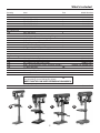
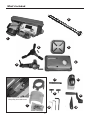
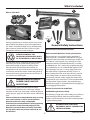
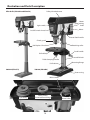
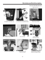
Code 505024
Code 700099
Code 700100
Code 700101
Pillar Drills
Axminster Tool Centre,
Unit 10 Weycroft Avenue, Axminster, Devon EX13 5PH
axminster.co.uk
Index of Contents
Index of Contents
02
Declaration of Conformaity
02
What’s Included
03-04-05-06
General Safety Instructions
06
General Safety Instructions for Drilling Machines
06-07
Specification07
Assembly08-09-10-11-12-13
Illustration and Parts Description
14-15-16-17-18-19
Changing the Speed
20-21
Speed Select Table
22
Removing the Chuck Assembly
23
Maintenance24
Parts Breakdown/List
25-26-27-28-29-30
Notes31
Declaration of Conformity
The undersigned,
authorised by Laizhou Light
Industry Machinery Plant No. 989 Laizhou North Road,
Laizhou, Shandong 261400, China declares that this product:
ZQJ4119-3
Drill Press
manufactured by Laizhou Light Industry Machinery Plant is
in compliance with the following standards or standardisation
documents in accordance with Council Directives
DIN EN 60204-1:1998-11
Machinery Directive 98/37/EEC, Annex 1
Amended 93/68/EEC
The undersigned,
authorised by Shandong
Laizhou Light Industry Machinery Plant No. 989, North Lai
Zhou Road Laizhou, Shandong 261400 P. R. China
declares that this product
ZQJ4116Q
Drill Press
manufactured by Shandong Laizhou Light Industry
Machinery Plant is in compliance with the following
standards or standardisation documents in accordance
with Council Directives
The undersigned, authorised by Laizhou Plant
Machinery Co., Ltd 989 North Lasi Zhou Road Laizhou,
Shandong declares that this product:
EN 55014-1: 1993+A1
EN 61000-3-2: 1995+A13
EN 61000-3-3: 1995
EN 55014-2: 1997
Declaration of Conformity
Copied from CE Cer
ZQJ4113,ZQJ4119K
Drill Press
manufactured by Laizhou Plant Machinery Co. is in
compliance with the following standards or standardisation
documents in accordance with Council Directives
Warning
Fully read manual
and safety instructions
before use
Ear protection
should be worn
The symbols below advise that you follow
the correct safety procedures when using
this machine.
Eye protection
should be worn
2
Two man assembly
HAZARD
Motor gets hot
What’s Included
Quantity
Item Part
1 No
ED16F2 Pillar Drill
ED16B2 Pillar Drill
ED16SB Pillar Drill
WD13L Pillar Drill
A
B
C
D
Box Containing:
1 No
1 No
1 No
1 No
1 No
1 No
1 No
1 No
Pillar drill head
Base
Drill pillar complete with mounting flange,
rise and fall rack and retaining ring
Drill table mounting bracket arm
Drill table
Lever feed handle assembly Drill guard with Phillips screws
Crank handle for table rise and fall mechanism
1
2
Bag Containing:
2 No
2 No
3 No
4 No
1 No
1 No
1 No
1 No
3 No
A
Code: 505024
Code: 700100
Code: 700101
Code: 700099
3
4
5
6
7
8
Motor yoke butterfly knobs
9
M8 x 20mm Hex bolt and washers
M8 x 20mm Hex bolt and washers
M10 x 25mm Hex bolts spring and plain washers
3-5-6mm Hex keys
10
3mm Hex key
10
Morse taper arbor for the chuck
11
Morse taper drift
12
Box containing 3-16mm B16 keyless chuck
Box containing 13mm B16 keyless chuck
Model Number
(700101 ONLY)
(700101 ONLY)
(700099 ONLY)
(505024 and 700100 ONLY)
(700099 Only)
13
(NOTE CHUCKS CAN VARY DEPENDING ON MODEL)
14
Lever feed handles
B
C
3
(700099 Only)
D
What’s Included
3
1
6
5
2
4
11
13
9
8
Guard shield and screws inside
the pulley drive belt cover
7
10
4
12
What’s Included
3
WD13L Pillar Drill
1
5
2
7
13
10
Having unpacked your machine and its accessories,
please check the contents against the equipment
list ”What’s Included”, if there are any discrepancies,
please contact Axminster Tool Centre using the
procedures laid down in the catalogue.
14
General Safety Instructions
Work Place/Environment/Installation
Mains Powered Machines/ Primary Precautions
PLEASE DISPOSE OF THE
PACKAGING RESPONSIBLY; MUCH
OF THE MATERIAL IS RECYCLABLE
These machines are supplied with a moulded 13
Amp. Plug and 3 core power cable. Before using the
machine inspect the cable and the plug to make sure
that neither are damaged. If any damage is visible
have the machine inspected/repaired by a suitably
qualified person. If it is necessary to replace the plug,
it is preferable to use an ‘unbreakable’ type that will
resist damage. Only use a 13 Amp plug, make sure
the cable clamp is tightened securely. Fuse at 13
Amp. If extension leads are to be used, carry out the
same safety checks on them, and ensure that they
are correctly rated to safely supply the current that
is required for your machine. It is also recommended
that the power supply outlet is the switched type,
and that the supply is switched off whilst plugging in,
or unplugging the machine.
The machine and its accessories will arrive coated
with heavy corrosion preventative grease and
greased wax paper or plastic wrapping. These
will need to be cleaned from the machine, its
components and accessories prior to it being set up
and commissioned. Use water soluble de greaser to
remove the barrier grease. Be warned, it will stain if
you splash it on clothing etc.
WARNING! WEAR OVERALLS,
RUBBER GLOVES AND EYE
PROTECTION!
After cleaning, lightly coat the exposed metal
surfaces of the machine with a thin layer of light
machine oil. N.B If you used water soluble de greaser
make sure you apply this thin film sooner rather than
later.
Please read the Instruction Manual prior to using
your new machine; as well as the installation
procedure, there are daily and periodic
maintenance recommendations to help you keep
your machine on top line and prolong its life.
Keep this Instruction Manual readily accessible
for any others who may also be required to use
the machine.
General Instructions for 230V Tools
Good Working Practices/Safety
The following suggestions will enable you to observe
good working practices, keep yourself and fellow
workers safe and maintain your tools and equipment
in good working order.
WARNING! KEEP TOOLS AND
EQUIPMENT OUT OF THE REACH OF
YOUNG CHILDREN!
5
Continues Over...
What’s Included
Keep the machine clean; it will enable you to more
easily see any damage that may have occurred.
Work Place/Environment
Do not use when or where it is liable to get wet. If
the machine is to be used outside and it starts to rain
stop work and move it inside. If machine has got wet;
dry it off as soon as possible, with a cloth or paper
towel.
Clean the machine with a damp soapy cloth if needs
be, do not use any solvents or cleaners, as these may
cause damage to any plastic parts or to the electrical
components.
Do not use 230Va.c. powered machines anywhere
within a site area that is flooded or puddled, and do
not trail extension cables across wet areas.
Keep the work area as uncluttered as is practical, this
includes personnel as well as material.
WARNING! UNDER NO
CIRCUMSTANCES SHOULD
CHILDREN BE ALLOWED IN WORK
AREAS!
General Safety Instructions
It is good practice to leave the machine unplugged
until work is about to commence, also make sure
to unplug the machine when it is not in use, or
unattended. Always disconnect by pulling on the
plug body and not the cable.
rotating parts of the machine, likewise, consideration
should be given to the removal of rings and
wristwatches, if these are liable to be a ‘snag’ hazard.
Consideration should also be given to non-slip
footwear, etc.
Once you are ready to commence work, remove any
tools used in the setting operations (if any) and place
safely out of the way. Re-connect the machine. Carry
out a final check e.g. check the drill bit is securely
tightened in the machine, check you have the correct
speed and function set, check that the power cable
will not ‘snag’ etc.
DO NOT work with cutting or boring tools of any
description if you are tired, your attention is
Wandering or you are being subjected to distraction.
A deep cut, a lost fingertip or worse; is not worth it!
DO NOT use this machine within the designated
safety areas of flammable liquid stores or in
areas where there may be volatile gases. There are
very expensive, very specialised machines for
working in these areas, THIS IS NOT ONE OF THEM.
Make sure you are comfortable before you start
work, balanced, not reaching etc. If the work you are
carrying out is liable to generate flying grit, dust or
chips, wear the appropriate safety clothing, goggles,
gloves, masks etc., If the work operation appears
to be excessively noisy, wear ear-defenders. If you
wear your hair in a long style, wearing a cap, safety
helmet, hairnet, even a sweatband, will minimise
the possibility of your hair being caught up in the
CHECK that drills are the correct type and size, are
undamaged and are kept clean and sharp, this will
maintain their operating performance and lessen the
loading on the machine. Above all, OBSERVE…. make
sure you know what is happening around you, and
USE YOUR COMMON SENSE.
General Safety Instructions for Drilling Machines
1. Do not operate the machine without carrying out a
preliminary inspection.
4. Make sure that the drillhead, the table bracket
arm, the table tilt and the table swivel clamps are all
locked before any drilling is attempted.
2. Check that the speed is correct for the planned
operation, and the upper drive belt cover is closed
and fastened secure.
3. Check the drill bit is the correct size and type, is
correctly fitted and tightened in the chuck.
5. Do not attempt to carry out any drilling operation
on material that has not been secured to the drill
table, either by vise or clamp.
6
6. Remove any tools (chuck key, spanners etc), that
General Safety Instructions for Drilling Machines
may have been used in setting up operations and put
them away in their correct stowage positions.
11. It is not a good idea to wear gloves when
operating a drill press.
7. Try to arrange the drilling operation so that the drill
tip does not come in contact with the table.
12. After the job is completed, remove all tools and
accessories from the machine, check that drill bits are
still sharp and re-use able.
8. Always allow the drill to stop before removing
drillings or swarf from around the job or the table.
13. Clean the machine down thoroughly, including
removing coolant or cutting compounds from the
drill table.
9. NEVER remove ‘flying’ swarf strands from the drill
whilst it is turning.
14. Lightly coat all metal surfaces with a light oil
coating.
10. It is a good precaution to wear eye protection
when drilling, especially using small drills, or very
hard material that produces small chips.
15. Disconnect the machine from the supply. Secure
the cable/plug clear of the floor.
Specification
Model
Code
Rating
Power
Speed Range
Throat Chuck Cap/Type
Chuck Travel
Max Chuck to Table
Max Chuck to Base
Diameter of Column
Table Size
Table Tilt
Base Size Overall L x W x H
Weight
Model
Code
Rating
Power
Speed Range
Throat Chuck Cap/Type
Chuck Travel
Max Chuck to Table
Max Chuck to Base
Table Size
Table Tilt
Base Size Overall L x W x H
Weight
ED16F2
505024
Trade
650W 230V
120-2580 rpm
178mm
3-16mm keyless
80mm
680mm
1,170mm
80mm
290 x 290mm
45° - 0 - 45°
450 x 270mm
710 x 350 x 1,645mm
88kg
Model
Code
Rating
Power
Speed Range
Throat Chuck Cap/Type
Chuck Travel
Max Chuck to Table
Max Chuck to Base
Diameter of Column
Table Size
Table Tilt
Base Size Overall L x W x H
Weight
ED16SB
700101
Hobby
370W
(5) 460-2890rpm
127mm
16mm keyless
60mm
315mm
430mm
200 x 200mm
45° - 0 - 45°
340 x 210mm
310 x 520 x 840mm
37kg
Model
Code
Rating
Power
Speed Range
Throat Chuck Cap/Type
Chuck Travel
Max Chuck to Table
Max Chuck to Base
Table Size
Table Tilt
Base Size Overall L x W x H
Weight
7
ED16B2
700100
Trade
650W
120-2580 rpm
178mm
3-16mm keyless
80mm
310mm
510mm
80mm
290 x 290mm
45° - 0 - 45°
450 x 270mm
710 x 350 x 1,015mm
82kg
WD13L
700099
Hobby
250W
(5) 600 - 2,500rpm
105mm
13mm keyless
50mm
215mm
370mm
160 x 160mm
45°-0-45°
290 x 180mm
240 x 470 x 735mm
20kg
Assembly
it to slide down the column until the rise and fall
rack is located in the cup chamfer in the top of the
mounting flange (see figs 9-10). Replace the cup
chamfered retaining collar over the column and slide
it down onto the top of the rack. Lock it in place with
the grub screw, ensuring that it has captured the
upper end of the rack securely, but not too tight that
the rack can not be swivelled around the pillar (see
fig 3).
Assembly for ED16F2-ED16B2-ED16SB Pillar Drills
Please read through the section entitled
illustration and parts description, to
identify the parts quickly and easily.
WARNING! The drillhead is a
heavy and substantial piece
of machinery, you are advised
to have help to lift it clear
of the box and fit it to the
column.
Check that the bracket can be driven up and down
the column and can swivel around the pillar. Locate
the Bristol clamping handle at the rear of the bracket
and tighten, (see fig 11) check it has ‘pinched’ up on
the column and the bracket is immobile; both in it’s
up and down travel and swivel movement.
For ED16SB ONLY (Motor Yoke Butterfly Clamps)
Place the drill head on upside down on the work
bench and remove the two Hex bolts (A) from
the drill head with a spanner, (see fig 1) place the
Hex bolts safely aside in readiness for mounting
the column to the base. Locate the two motor
yoke butterfly knobs (9) and screw them into the
threaded holes, (see fig 1)
Fit the drill table (5), identify the Bristol clamping
handle at the front of the bracket and tighten, (see fig
12) check it has ‘pinched’ up on the drill table spigot
and the drill table is immobile.
CHECK the drill head, ensure that the two hex
socket grub screws that lock the head in place on
the column are withdrawn and will not foul on the
column (3) when the head is fitted (see fig 13). Put
the lower assembly you have just been working on
in the designated position, make sure it is stable
and lift the drillhead (1) over the column (3) and
let it drop into place (see fig 14). Set the drill head
approximately fore and aft and lock in position using
the two caphead grub screws mentioned earlier.
Check that the drillhead is immobile. Everything on
the drilling machine is now secured.
Place the base (2) on the bench or (floor) and place
the mounting flange of the column (3) onto the
seating flange of the base, align the holes. Use the
four Hex bolts and plain washers secure the column
to the base (see fig 2). Loosen the socket grubs crew
holding the cup chamfered retaining collar to the
column (with the supplied Hex key), remove it and
the rise and fall rack, put aside (see fig 3).
Take the drill table mounting bracket arm (4) and
twist the worm drive shaft with your fingers such that
the whole shaft protrudes from the casting and the
worm gear itself is clear of the square recess in the
main body of the casting (see fig 4).
Once the drilling machine is correctly positioned and,
if necessary, fastened down; you can proceed with
the final assembly.
Locate and fit the crank handle (8) to the shaft,
ensuring that you tighten the grub screw onto the
machined flat on the shaft. This will keep the worm
gear in position (see figs 4-5). Pick up the rise and
fall gear rack, identify the top and the bottom, (the
rack gearing is cut asymmetrically, with the gear cut
extending closer to the bottom), make sure you have
the rack the right way up, as it will allow you to drive
the drill table up and down over its full range (see
fig 6).
Fit the rise and fall rack into the square recess in the
mounting body casting, ensure that it is engaged
with the pinion, (see figs 7-8) and lower the
combined mechanism over the column (3). Allow
Locate the lever feed handle (6) and it’s securing
screw, note the raised boss of the feed mechanism
and the spigot next to it (see fig 15). Mount the
handle over the boss and ensure the spigot hole in
the handle engages the spigot on the mechanism.
Secure with the supplied caphead bolt and washer
through the hole in the centre of the handle through
to the tapped hole in the mounting boss (see fig 16).
Locate the guard moulding, shield and Phillips screws
(7). Insert the shield into the guard moulding’s recess
and line up the three pre-drilled holes and secure
with the Phillips screws (see fig 17-18).
8
Assembly
Take the chuck guard and fit to the lower bearing
flange of the quill mounting. Tighten the screw and
nut fastening so that the drill guard is securely held
in place (see fig 19).
Fig 04
Fig 01
A
4
A
Worm drive shaft
Machined flat
9
9
Fig 05
Fig 02
3
8
Hex Bolts
2
Fig 06-07-08
Mounting flange
Fig 03
Top of rack
Grub screw
Retaining collar
9
Continues Over...
Assembly
Cup chamfer
Pinion
4
Fig 11
Bristol clamping handle
Rise and fall rack
Fig 12
Fig 09-10
5
3
Bristol clamping handle
4
Fig 13
Grub screw
Grub screw
10
Assembly
Fig 14
Fig 17-18
1
7
WARNING! The drillhead is a
heavy and substantial piece
of machinery, you are advised
to have help to lift it clear
of the box and fit it to the
column.
Phillips screw
Fig 15
Raised boss
Fig 19
Spigot
6
Fig 16
Fit the guard assembly to the lower bearing flange of
the quill mounting, tighten the screw and nut so that
the drill guard is securely held in place.
Morse taper arbor and chuck
Locate the morse taper arbor (11) and the B16 keyless
chuck (13). Insert the arbor into the keyless chuck as
shown in (fig 20). Insert the other end of the arbor
(11) up into the lower bearing flange in the quill until
the assembly locks in place, (see fig 21)
11
Continues Over...
Assembly
Fig 20
Table
11
Locate the table/support assembly and slide it down
the column until it rests on the base plate. Insert the
bristol clamping handle into the threaded hole to
the side of the table casting, slide the table up the
column to working height and clamp the table in
position, (see figs 23-24).
Morse taper arbor
Fig 23
13
Insert the arbor into the keyless chuck as shown
Fig 21
Lower bearing flange
Fig 24
Insert the other end of the arbor up into the quill
until the assembly locks in place
Assembly for WD13L Pillar Drill
Mounting the column
Place the mounting flange of the column (3) onto the
seating flange of the base. Align the holes. Locate the
two M8 Hex bolts you removed earlier from the drill
head and the extra hex bolts and 8mm plain washers
and secure the column to the base with a 13mm
spanner, (see fig 22).
Fig 22
Guard shield
Locate the guard shield and Phillips screws (7). Insert
the shield into the guard moulding’s recess and line
up the three pre-drilled holes and secure with the
Phillips screws, (See figs 25-26
12
Assembly
Fig 25-26
Fig 28
Guard moulding
14
Guard shield
Pillar drill head
Pre-drilled hole
WARNING! The drillhead is a
heavy and substantial piece
of machinery, you are advised
to have help!
Line up the three pre-drilled holes and secure with
the Phillips screws
Using the 3mm Hex key loosen the two grub screws
to the right side of the head, (see fig 29) lift the drill
head above the column and let it drop into place.
Fig 29
Keyless chuck
Insert the keyless chuck (13) over the morse taper
arbor as shown in (fig 27) and press home.
Fig 27
13
Lever feed handles
Locate the three lever handles (14) and screw them
into the threaded holes on the feed shaft, (See fig 28)
Set the drillhead approximately fore and aft and
lock in position using the two caphead grub screws
mentioned earlier.
Check that the drillhead is immobile. Everything on
the drilling machine is now secured, and if you now
wish to move it to its preferred workplace, nothing
should slew during the lift and move. Once the
drilling machine is correctly positioned and fastened
down, it is ready for use.
13
Illustration and Parts Description
Pillar Drills (ED16B2 and ED16F2)
Pulley drive belt cover
Motor
yoke locking
knob
Light switch
Motor
On/Off switch shroud
Lever Feed handle
Chuck guard
B16 Keyless Chuck
Retaining collar
Crank handle
Drill table
Rise and fall rack
Table clamping handle
Mounting flange
Drill column
505024 (ED16F2)
700100 (ED16B2)
Base casting
Micro switch
Quill Pulley
Jockey Pulley
(Drive belt tensioning)
14
Motor Pulley
Illustration and Parts Description
Pillar Drills (ED16B2 and ED16F2)
Depth stop nuts
A
B
OFF
ON
B
A
A
B
On/Off switch (A)
Emergency stop button (B)
Motor yoke butterfly knob (A)
Drive belt tensioning lever lock (B)
Depth stop assembly (A)
Depth stop scale (B)
A
B
Pillar drill light switch
Pillar drill light
Chuck guard (A)
Keyless chuck (B)
B
A
A
B
Quill lower bearing flange
Table tilt pointer (A)
Table tilt scale (B)
15
Table clamping handle (A)
Table tilt clamping bolt (B)
Illustration and Parts Description
Pulley drive belt cover
Pillar Drill (ED16SB)
Motor yoke locking knob
On/Off switch shroud
Motor
Depth stop clamp
Lever Feed handle
Chuck guard
Retaining collar
B16 Keyless Chuck
Drill table
Crank handle
Table clamping handle
Rise and fall rack
Drill column
Mounting flange
Base casting
700101 (ED16SB)
Micro switch
Quill pulley
Motor pulley
Pulley belt
16
Illustration and Parts Description
Pillar Drill (ED16SB)
Motor yoke butterfly locking knob
Drill table mounting
bracket clamping handle
Table clamping handle
B
A
A
Table tilt clamping bolt
B
On/Off switch (A)
Emergency stop button (B)
Table tilt pointer (A)
Table tilt scale (B)
Depth stop butterfly clamp
Chuck guard
B
A
Depth scale (A)
Depth scale pointer (B)
17
Illustration and Parts Description
Pillar Drill (WD13L)
Pulley drive belt cover
Motor yoke locking knob
On/Off switch shroud
Depth stop clamping nut
Motor
Chuck guard
Lever Feed handle
B16 Keyless Chuck
Drill table
Drill column
Mounting flange
Base casting
700099 (WD13L)
Micro switch
Quill pulley
Motor pulley
Pulley belt
18
Illustration and Parts Description
Pillar Drill (WD13L)
Drill table mounting
bracket clamping handle
Depth stop nuts
Motor yoke butterfly locking knob
Depth stop clamping screw/nut
Pointer
A
B
A
Depth stop assembly (A)
Depth stop scale (B)
B
Chuck guard assembly
19
Table tilt pointer (A)
Table tilt scale (B)
Changing the Speed
Fig 32-33-34-35
WARNING! DISCONNECT THE
PILLAR DRILL FROM THE MAINS
SUPPLY BEFORE CONTINUING!
Remove the securing screw from the side of the
pulley and drive belt cover, put carefully aside
and raise the cover (See fig 30).
Turn clockwise to
tension the belts
Fig 30
Pillar Drills (ED16B2 and ED16F2) Only
Locate and loosen the motor yoke butterfly locks
(A). Locate the drive belt tensioning lever (B), (see
fig 31) and turn it un-clockwise, to move the motor
assembly “in”. This will release the tension from the
drive belts (See figs 32-33-34-35).
Fig 31
A
Turn anti-clockwise
to slacken the belts
B
Refer to the (speed select table) and ascertain the
belt positions for the speed you require. Move the
belts to these positions.
WARNING! TAKE CARE NOT TO
TRAP YOUR FINGERS WHEN
REPOSITIONING THE BELT ON
THE PULLEYS!
Turn the pulley train to check the belts move freely.
Tension the whole belt train by turning the drive belt
20
Changing the Speed
tensioning lever (B) clockwise, to move the motor
assembly “out”. Tighten the motor yoke butterfly
knobs (A) to lock the motor assembly in position.
Pillar Drill (WD13L) Only
Pillar Drill (ED16SB) Only
To release the tension on (ED16SB) loosen the two
motor yoke locks on either side of drilllhead, push the
motor assembly up against the drillhead casting, thus
releasing the tension on the pulleys, (See figs 36-37).
Refer to the (speed select table) and ascertain the
belt positions for the speed you require.
To release the tention loosen the motor yoke
tensioning lock which loosens the tension on the
spring, push the motor up against the drillhead
casting, thus releasing the tension on the pulleys,
(See fig 38).
Fig 38
Tensioning spring
Fig 36-37
Motor yoke lock
Motor yoke lock
WARNING! TAKE CARE NOT TO
TRAP YOUR FINGERS WHEN
REPOSITIONING THE BELT ON
THE PULLEYS!
WARNING! TAKE CARE NOT TO
TRAP YOUR FINGERS WHEN
REPOSITIONING THE BELT ON
THE PULLEYS!
Turn the pulleys to check the belts move freely.
Tension the pulleys by pushing the motor assembly
out and securing the motor yoke butterfly knob to
lock the motor assembly in position. Lower the belt
and pulley cover carefully, (remember the micro
switch) refit the securing screw and tighten.
Turn the pulleys to check the belts move freely.
Tension the pulleys by pushing the motor assembly
out and securing the motor yoke butterfly knobs to
lock the motor assembly in position.
RE-CONNECT THE SUPPLY AND
SWITCH ON. Check the drill runs
smoothly, no hard vibration etc.
If all seems satisfactory, recommence drilling
operations.
21
Speed Select Table
700100 (ED16B2)- 505024 (ED16F2) Pillar Drills
7000101 (ED16SB) Pillar Drill
700099 (WD13L) Pillar Drill
22
Removing the Chuck Assembly
Removing the chuck
Preparation
While holding the handle in place turn the chuck
to line up the morse taper arbor (11) in the quills
machined slot, (See fig 40). Insert the morse taper
drift (12) in the quills slot, thus pushing the morse
taper down and releasing the chuck, (See fig 41).
You wil require the morse taper drift (12)
Pillar Drill (ED16SB) Only
Lower the quill to it’s maximum depth by turning
the feed lever handle. while holding the handle turn
the depth scale ring (A) fully round and then tighten
the butterfly depth stop knob (B) to lock the quill in
position, (See fig 39)
Fig 40
11
Fig 39
B
Morse taper arbor
Quill slot
Fig 41
A
Morse taper drift
Pillar Drill (ED16B2-ED16F2)
Place a piece of timber on the drill table to prevent
the chuck from being damaged and lower the quill to
it’s maximum depth by turning the feed lever handle.
23
12
Maintenance
WARNING! DISCONNECT THE
MACHINE FROM THE MAINS
SUPPLY BEFORE CONTINUING!
Motor speed
The speed of the motor cannot be regulated or
changed - no adjustment is necessary.
Oiling points
Cleaning
Excessive dust in the motor can cause excessive heat
to develop. Every effort should be made to prevent
foreign material from entering the motor.
When operated under conditions likely to permit
accumulations of dust, dirt or waste, a visual
inspection should be made at frequent intervals.
Accumulations of dry dust can usually be blown out
successfully.
Caution: To avoid eye injury or adverse reaction
to dust, high pressure hoses should not be used
especially in poorly ventilated areas. The operator
performing this cleaning function should wear
safety goggles and dust filter mask.
After cleaning all dust and debris a light coating of
machine oil on the quill then to spread the oil.
If the machine is going to stand idle for any length
of time, a light coat of spray or machine oil over the
column and table will prevent rusting.
Electrics
WARNING! DO NOT USE THE
MACHINE IF THE POWER CABLE
HAS BECOME DAMAGED
If any servicing (other than the above cleaning)
becomes necessary the unit should be returned
to Axminster tool centre to be repaired by one of
our qualified electrician. Contact our technical sales
department for further assistance.
Call 03332 406406
Email [email protected]
WARNING! DO NOT ATTEMPED TO
REPAIR IT YOUR SELF CONTACT
OUR TECHNICAL SALES TEAM FOR
ASSSISTANCE!
24
Parts Breakdown/List
Pillar Drills 505024 (ED16F) 700100 (ED16B2)
25
Parts Breakdown/List
Pillar Drills 505024 (ED16F) 700100 (ED16B2)
1
2
3
4
5
6
7
8
9
10
11
12
13
14
15
16
17
18
19
20
21
22
23
24
25
26
27
28
29
30
31
32
33
34
35
36
37
38
39
40
41
42
43
44
45
46
47
48
49
50
51
52
53
54
BASE
COLUMN SHOULDER
RACK
COLUMN
HEX BOLT
SCREW
MARK
TABLE BRACKET
CLAMP BOLT
WORM GEAR
SHAFT
HANDLE
GEAR
RACK RING
SET SCREW
TABLE
TABLE BOLT
TABLE ARM BRACKET
HEX BOLT
PIN
MARK
SCREW
WRENCH 5mm
WRENCH 3mm
POWER CORD
SCREW
COVER
NUT
SPRING CAP
TORSION SPRING
SPRING COVER
NUT
SCREW SPECIAL SET
SHIFTER BAR
C-CLIP
SLIDE BAR BOLT
SLIDE BAR
SLIDE BAR
WASHER
MOTOR BASE
NUT
MOTOR PULLEY
V-BELT
PULLEY COVER
SET SCREW
MOTOR
KEY
NUT
WASHER
HEX BOLT
BODY
CENTER SHAFT
C-CLIP
BALL BEARING
1
1
1
1
4
2
1
1
1
1
1
1
1
4
1
1
1
1
2
1
1
2
1
1
1
3
1
2
1
1
1
1
1
1
1
2
1
1
2
2
2
1
1
1
1
1
1
4
4
4
1
1
1
1
26
55
56
57
58
59
60
61
62
63
64
65
66
67
68
69
70
71
72
73
74
75
76
77
78
79
80
81
82
83
84
85
86
87
88
89
90
91
92
93
94
95
96
97
98
99
100
101
102
103
104
105
106
107
108
109
CENTER PULLEY
C-CLIP
SCREW
KNOB
WASHER
SPEED CHART LABEL
SCREW
WASHER
HEX BOLT
SHIFTER
SET SCREW
SET SCREW
SET SCREW
DEPTH RING
FEED SHAFT
HANDLE
HANDLE COVER
CAP BOLT
V-BELT
SCREW
SWITCH BOX
SCREW
WASHER
WASHER
SCREW
SWITCH
NUT
SCREW
SCALE
SCALE BASE
C--CLIP
BALL BEARING
RUBBER WASHER
SPINDLE SLEEVE
WEDGE
BALL BEARING
CAP BOLT
PLATE
SPINDLE
ARBOR
CHUCK
CHUCK KEY
NUT
C--CLIP
BALL BEARING
SPACER
BALL BEARING
INSERT PULLEY
SPINDLE PULLEY
PULLEY NUT
NUT
LIGHT BODY
LIGHT BASE
SCREW
LIGHT SCREW
1
1
1
1
1
1
4
4
1
1
1
1
2
1
1
1
1
1
1
2
1
2
2
1
2
1
3
2
1
1
1
1
1
1
1
1
1
1
1
1
1
1
1
1
1
1
1
1
1
1
1
1
1
1
Parts Breakdown/List
Pillar Drill 700101 (ED16SB)
27
Parts Breakdown/List
Pillar Drill 700101 (ED16SB)
28
Parts Breakdown/List
Pillar Drill 700099 (WD13L)
29
Parts Breakdown/List
Pillar Drill 700099 (WD13L)
30
Notes
31
Please dispose of packaging for the product in a responsible manner. It is suitable for recycling.
Help to protect the environment, take the packaging to the local recycling centre and place into
the appropriate recycling bin.
Only for EU countries
Do not dispose of electric tools together with household waste material. In observance of
European Directive 2002/96/EC on waste electrical and electronic equipment and its
implementation in accordance with national law, electric tools that have reached the end of their
life must be collected separately and returned to an environmentally compatible recycling facility.