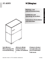
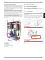
1
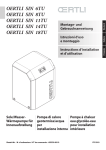
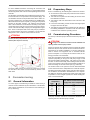
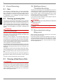
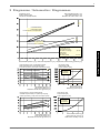
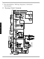
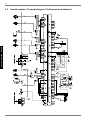
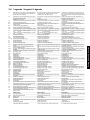
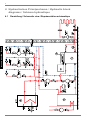
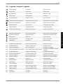
Sole/WasserWärmepumpe für Innenaufstellung Installation and Operating Instructions English Instructions d’installation et d’utilisation Français Montage- und Gebrauchsanweisung Brine-to-Water Heat Pump for Indoor Installation Bestell-Nr. / Order no. / No de commande : 452234.66.03 Deutsch SI 40HS Pompe à chaleur eau glycolée-eau pour installation intérieure FD 8708 Table of contents 1 Read immediately..........................................................................................................................E-2 1.1 Important Information.............................................................................................................................. E-2 1.2 Legal Provisions and Guidelines ............................................................................................................ E-2 1.3 Energy-Efficient Use of the Heat Pump .................................................................................................. E-2 2 Purpose of the heat pump ............................................................................................................E-2 3 Baseline Unit..................................................................................................................................E-3 4 Accessories ...................................................................................................................................E-3 4.1 Connecting Flanges................................................................................................................................ E-3 5 Transport........................................................................................................................................E-3 6 Installation .....................................................................................................................................E-4 6.1 General Information ................................................................................................................................ E-4 6.2 Sound Emissions .................................................................................................................................... E-4 7 Mounting ........................................................................................................................................E-4 7.1 7.2 7.3 7.4 8 General Information ................................................................................................................................ E-4 Connection on Heating Side ................................................................................................................... E-4 Connection on Heat Source Side ........................................................................................................... E-4 Electrical Connection .............................................................................................................................. E-4 Commissioning .............................................................................................................................E-5 8.1 General Information ................................................................................................................................ E-5 8.2 Preparatory Steps................................................................................................................................... E-5 8.3 Commissioning Procedure...................................................................................................................... E-5 9 Care/Cleaning ................................................................................................................................E-6 9.1 Care ........................................................................................................................................................ E-6 9.2 Cleaning og Heating Side ....................................................................................................................... E-6 9.3 Cleaning of Heat Source Side ................................................................................................................ E-6 10 Malfunctions / Troubleshooting ...................................................................................................E-6 11 Decommissioning / Disposal .......................................................................................................E-6 12 Equipment Data .............................................................................................................................E-7 Anhang / Appendix / Annexes ............................................................................................................ A-I www.dimplex.de E-1 English 2.1 Application .............................................................................................................................................. E-2 2.2 Principle of Operation ............................................................................................................................. E-2 1 1 Read immediately 1.1 Important Information ATTENTION! Any work on the heat pump may only be performed by an authorised and qualified customer service. ATTENTION! The heat pump must not be tilted more than max. 45° (in either direction). English ATTENTION! 1.3 Energy-Efficient Use of the Heat Pump By operating this heat pump you contribute to the protection of our environment. A prerequisite for an efficient operation is the proper design and sizing of the heating system and the heat source system. In particular, it is important to keep water flow temperatures as low as possible. All energy consumers connected should therefore be suitable for low flow temperatures. A 1 K higher heating water temperature corresponds to an increase in power consumption of approx. 2.5 %. Low-temperature heating systems with flow temperatures between 30 °C and 50 °C are optimally suited for energy-efficient operation. The transport securing devices must be removed prior to commissioning. ATTENTION! The heating system must be flushed prior to connecting the heat pump. 2 ATTENTION! The supplied strainer must be fitted in the heat source inlet of the heat pump in order to protect the evaporator against the ingress of impurities. ATTENTION! The brine solution must contain at least 25 % of an antifreeze agent on a mono-ethylene glycol or propylene glycol basis and must be mixed prior to filling. ATTENTION! The clockwise phase sequence must be observed when connecting the load lines (the heat pump will deliver no output and will be very noisy when the phase sequence is incorrect). ATTENTION! Commissioning is to be effected in accordance with the installation and operating manual of the heat pump controller. ATTENTION! To prevent the accumulation of deposits (e.g. rust) we recommend using a suitable corrosion protection system. ATTENTION! Disconnect all electrical circuits from the power supply before opening the enclosure. 1.2 Legal Provisions and Guidelines This heat pump conforms to all relevant DIN/VDE regulations and EU directives. For details refer to the EC Declaration of Conformity in the appendix. The electrical connection of the heat pump must be performed according to and conforming with all relevant VDE, EN and IEC standards. Beyond that, the connection requirements of the local utility companies have to be observed. The heat pump is to be connected to the heat source and heat distribution systems in accord-ance with all applicable provisions. ATTENTION! Any work on the heat pump may only be performed by an authorised and qualified customer service. E-2 2.1 Purpose of the heat pump Application The brine-to-water heat pump is designed for use in existing or newly built heating systems. Brine is used as the heat carrier in the heat source system. Ground coils, ground collectors or similar systems can be used as the heat source. 2.2 Principle of Operation The heat generated by the sun, wind and rain is stored in the ground. This heat stored in the ground is collected at low temperature by the brine circulating in the ground collector, ground coil or similar device. A circulating pump then conveys the warmed brine to the evaporator of the heat pump. There, the heat is given off to the refrigerant in the refrigeration cycle. When so doing, the brine cools so that it can again take up heat energy in the brine circuit. The refrigerant is drawn in by the electrically driven compressor, is compressed and "pumped" to a higher temperature level. The electrical power needed to run the compressor is not lost in this process, but most of the generated heat is transferred to the refrigerant. Subsequently, the refrigerant is passed through the condenser where it transfers its heat energy to the heating water. Based on the thermostat setting, the heating water is thus heated to up to 70 °C. 5 Baseline Unit 4 The baseline unit consists of a heat pump, ready for connection, for indoor installation, complete with sheet metal cabinet, control box and integrated controller. The refrigeration cycle contains the refrigerant R134a. Refrigerant R134a is CFC-free, non-ozone depleting and non-combustible. All components required for the operation of the heat pump are located in the control box. A sensor for the external wall temperature including mounting hardware as well as a strainer are supplied with the heat pump. The voltage supply for the load and control current must be provided by the customer. The control wire of the brine pump (to be provided by the customer) is to be connected to the control box. When so doing, a motor protecting device is to be installed, if required. The collector including the brine manifold must be provided by the customer. Accessories 4.1 Connecting Flanges The use of flat-sealing connecting flanges allows the unit, as an option, to be connected by means of flanges. 5 Transport For the transport by means of a hand truck or boiler trolley, position the latter under the front end of the unit below the transport security device. For transport on a level surface, the unit can be lifted from the rear or from the front by means of a lift truck or forklift. In this case, the transport securing device is not imperative. ATTENTION! The heat pump must not be tilted more than max. 45° (in either direction). 5HPRYHVFUHZLQ WUDQVSRUWORFN After the transport, the transport securing device is to be removed on either side at the bottom of the unit. 1) Control 2) Evaporator 3) Condenser 4) Compressor 5) Transport securing devices 6) Filter drier www.dimplex.de ATTENTION! The transport securing device is to be removed prior to commissioning. E-3 English 3 6 6 Installation 6.1 General Information As a rule, the unit must be installed indoors on a level, smooth and horizontal surface. The entire base frame should make full contact with the surface in order to ensure adequate sound insulation. Failing this, additional sound insulation measures may become necessary. English The heat pump should be installed to allow easy maintenance/ service access. This is ensured if a clearance of approx. 1 m in front of the heat pump is maintained. P Heating water minimum flow rate The heating water minimum flow rate through the heat pump must be assured in all operating states of the heating system. This can be accomplished, for example, by installing a differential pressure-free manifold or an overflow valve. The procedure for setting an overflow valve is described in the Chapter Commissioning. Frost protection for installations prone to frost Provided the controller and heating circulating pumps are ready for operation, the frost protection feature of the controller is active. If the heat pump is taken out of service or in the event of a power failure, the system has to be drained. In heat pump installations where a power failure cannot be readily detected (holiday house), the heating circuit must contain a suitable antifreeze product. 7.3 Connection on Heat Source Side The following procedure must be observed when making the connection: Connect the brine line to the flow and return pipe of the heat pump. P 6.2 Sound Emissions The heat pump offers silent operation due to efficient sound insulation. Any vibration transmission to the foundation or the heating system can be largely prevented by internal sound decoupling measures. 7 Mounting 7.1 General Information The following connections need to be estab-lished on the heat pump: supply/return flow of the brine system The hydraulic plumbing diagram must be observed here. ATTENTION! The supplied strainer must be fitted in the heat source inlet of the heat pump in order to protect the evaporator against the ingress of impurities. In addition, a microbubble deaerator must be installed in the heat source system. The brine liquid must be produced prior to charging the system. The brine concentration must be at least 25 %. Freeze protection down to -14°C can thus be ensured. Only antifreeze products on the basis of mono-ethylene glycol or propylene glycol may be used. The heat source system must be vented (de-aerated) and checked for leaks. ATTENTION! The brine solution must contain at least 25 % of an antifreeze agent on a mono-ethylene glycol or propylene glycol basis and must be mixed prior to filling. supply/return flow of the heating system power supply 7.2 Connection on Heating Side ATTENTION! The heating system must be flushed prior to connecting the heat pump. Before completing the heat pump connections on the heating water side, the heating installation must be flushed in order to remove any impurities that may be present, as well as residues of sealing material, and the like. Any accumulation of deposits in the condenser may result in a total failure of the heat pump. Once the installation on the heating side has been completed, the heating system must be filled, de-aerated and pressuretested. E-4 7.4 Electrical Connection The following electrical connections must be established on the heat pump: Connection of the control wire to terminals X1: L/N/PE in the control box of the heat pump. Connection of the load wire to terminals X5: L1/L2/L3/PE in the control box of the heat pump. Connection of the brine pump (to be supplied by the customer) to terminal PE and pump contactor K5: 2/4/6 on the control panel of the HP. All electrical components required for the operation of the heat pump are located in the control box. 8.3 An automatic circuit-breaker with simultaneous tripping of all external conductors is to be provided in the load power supply. The circuit-breaker must be an all-pole disconnect device with a contact gap of at least 3 mm. The same applies to any additional disable contactors that may be required, e.g. during shut-off periods imposed by the utility company. The required cross-sectional area of the conductors is to be selected according to the power consumption of the heat pump, the technical connection requirements of the relevant utility company and all applicable regulations. Power consumption data of the heat pump is provided in the product literature and on the nameplate. The terminals are designed for a max. conductor cross-section of 35 mm². ATTENTION! The clockwise phase sequence must be observed when connecting the load lines (the heat pump will deliver no output and will be very noisy when the phase sequence is incorrect). 8.2 Preparatory Steps Prior to commissioning, the following items need to be checked: All connections of the heat pump must have been made as described in Chapter 7. The heat source system and the heating circuit must have been filled and checked. The strainer must have been fitted in the sole inlet of the heat pump. In the brine and heating circuits all valves that might impair the proper flow must be open. The settings of the heat pump controller must be adapted to the heating installation in accordance with the instructions contained in the controller's operating manual. 8.3 Commissioning Procedure The start-up of the heat pump is effected via the heat pump controller. ATTENTION! Commissioning is to be effected in accordance with the installation and operating manual of the heat pump controller. Where an overflow valve is fitted to assure the minimum heating water flow rate, the valve must be set in accordance with the requirements of the heating installation. An incorrect setting may result in various error symptoms and an increased elec-tric power consumption. To correctly set the overflow valve, the following procedure is recommended: Close all of the heating circuits which may also be closed during operation (depending on the type of heat pump usage) so that the least favourable operating state - with respect to the water flow rate - is achieved. Normally, these heating circuits are those of the rooms located on the south and west sides of buildings. At least one heating circuit must remain open (e.g. bathroom). The power cable must be run through the guide tubes, inserted into the side of the control box and secured by means of the strain relief. 8 8.1 Commissioning General Information To ensure proper commissioning it should be carried out by a customer service authorised by the manufacturer. This will lead, under certain circumstances, to an extension of the warranty period (cf. Warranty). The overflow valve is to be opened to such an extent that based on the current heat source temperature the maximum temperature difference between heating supply and return flow temperature is obtained, as indicated in the table below. The temperature difference should be measured as closely to the heat pump as possible. In mono-energetic systems, the electric heating element is to be deactivated. Heat source temperature max. difference between heating supply and return temperature from to -5° C 0° C 1° C 5° C 11 K 6° C 9° C 12 K 13 K 10 K 10° C 14° C 15° C 20° C 14 K 21° C 25° C 15 K Any malfunctions occurring during operation are displayed on the heat pump controller and can be corrected as described in the operating manual of the heat pump controller. www.dimplex.de E-5 English For more detailed instructions concerning the connection and functioning of the heat pump controller (e.g. the supplied external wall sensor) please refer to the enclosed operating manual of the controller. 9 9 Care/Cleaning 9.1 Care The heat pump is maintenance-free. To prevent malfunctions due to sediments in the heat exchangers, care must be taken that no im-purities can enter the heat source system and the heating installation. In the event that operating malfunctions due to contamination occur nevertheless, the system should be cleaned as described below. English 9.2 Cleaning og Heating Side The ingress of oxygen into the heating water circuit, in particular if it contains steel components, may result in the formation of oxidation products (rust). These can enter the heating system via valves, circulating pumps or plastic tubing. It is therefore important - in particular with respect to the piping of underfloor heating systems - that the installation be executed in a diffusion-proof manner. ATTENTION! To prevent the accumulation of deposits (e.g. rust) we recommend using a suitable corrosion protection system. In the case of severe contamination leading to a reduction in the performance of the condenser in the heat pump, the system must be cleaned by a heating technician. Based on current knowledge, we recommend cleaning with a 5% phosphoric acid solution or, in the case that cleaning needs to be performed more frequently, with a 5% formic acid solution. In either case, the cleaning fluid should be at room temperature. It is recommended that the heat exchanger be cleaned in the direction opposite to the normal flow direction. To prevent acidic cleaning agents from entering the circuit of the heating installation we recommend that the flushing device be fitted directly to the supply and return lines of the condenser of the heat pump. Thereafter the system must be thoroughly flushed using appropriate neutralising agents in order to prevent any damage caused by cleaning agent residues that may still be present in the system. All acids must be used with great care, all relevant regulations of the employers' liability insurance associations must be adhered to. If in doubt, contact the manufacturer of the chemicals! 9.3 Cleaning of Heat Source Side ATTENTION! The supplied strainer must be fitted in the heat source inlet of the heat pump in order to protect the evaporator against the ingress of impurities. The filter screen of the strainer should be cleaned one day after commissioning, thereafter every week. If no more contamination can be noticed any more, the strainer filter can be removed in order to reduce pressure losses. E-6 10 Malfunctions / Troubleshooting This heat pump is a quality product and designed for trouble- and maintenance-free operation. In the event that a malfunction occurs nevertheless, it will be indicated on the display of the heat pump controller. Simply consult the Malfunctions and Troubleshooting table contained in the in-stallation and operating manual of the heat pump controller (manager). If you cannot correct the malfunction yourself, please contact the after-sales service agent in charge. ATTENTION! All work on the heat pump may only be performed by an authorised an qualified after-sales service. ATTENTION! Disconnect all electrical circuits from the power supply before opening the enclosure. 11 Decommissioning / Disposal Before removing the heat pump, disconnect the unit from the power source and close all valves. Environment-relevant requirements regarding the recovery, recycling and disposal of service fuels and components in accordance with all relevant standards must be adhered to. Particular attention must hereby be paid to the proper disposal of refrigerants and refrigeration oils. 12 12 Equipment Data Device information for brine-to-water heat pumps (heating only) 1 Type and order code 2 Design 2.1 Degree of protection according to EN 60 529 2.2 Installation location Performance data 3.1 Operating temperature limits: IP 21 Indoors Heating water flow °C Brine (heat source) °C up to 70 -5 to +25 Antifreeze Monoethylene glycol Minimum brine concentration (-13 °C freezing temperature) 3.2 3.3 Temperature spread of heating water (flow/return flow) at B0 / W35 Heat output / COP at B-5 / W55 1 at B0 / W45 1 at B0 / W50 1 at B0 / W35 1 3.4 25% 9.8 K kW / --- 2 28.9 / 2.4 kW / --- 3 10.6 / 2.1 kW / --- 2 kW / --- 3 kW / --- 2 33.1 / 3.1 kW / --- 3 13.5 / 2.4 kW / --- 2 36.6 / 4.4 kW / --- 3 18.6 / 4.4 5.0 31.7 / 3.2 12.9 / 2.5 34.2 / 4.1 17.4 / 4.1 Sound power level dB(A) 3.5 Sound pressure level at a distance of 1 m dB(A) 3.6 Heating water flow with an internal pressure differential of m³/h / Pa 3.7 Brine throughput with an internal pressure differential (heat source) of m³/h / Pa 3.8 Refrigerant; total filling weight type / kg 4 Dimensions, connections and weight 4.1 Device dimensions without connections 4 H x W x L mm 4.2 Device connections to heating system Inch G 1 1/2'' internal/external 4.3 Device connections to heat source Inch G 2 1/2'' internal/external 4.4 Weight of the transportable unit(s) incl. packing kg 5 Electrical connection 5.1 Nominal voltage; fuse protection V/A 5.2 Nominal power consumption 1 B0 W35 kW 5.3 Starting current with soft starter A 5.4 Nominal current B0 W35 / cos ϕ 2 A / --- 6 Complies with the European safety regulations 7 Additional model features 7.1 Water in device protected against freezing 6 7.2 Performance levels 7.3 English 3 SI 40HS Controller internal/external 65 50 3.2 / 1100 5.5 / 2900 11.0 / 11900 8.8 / 7800 R134a / 8.0 1890 x 1350 x 750 502 400 / 50 8.36 8.35 84 15.09 / 0.8 15.06 / 0.8 5 Yes 2 Internal 1. This data indicates the size and capacity of the system. For an analysis of the economic and energy efficiency of the system, both the bivalence point and the regulation should also be taken into consideration. The specified values, e.g. B10 / W55, have the following meaning: Heat source temperature 10 °C and heating water flow temperature 55 °C. 2. Operation with 2 compressor 3. Operation with 1 compressors 4. Note that additional space is required for pipe connections, operation and maintenance. 5. See CE declaration of conformity 6. The heat circulating pump and the heat pump controller must always be ready for operation. www.dimplex.de E-7 Anhang / Appendix / Annexes 1 Maßbild / Dimensioned drawing / Schéma coté ........................................................................ A-II 2 Diagramme / Schematics / Diagrammes ................................................................................... A-III 3 Stromlaufpläne / Wiring diagrams / Schémas électriques ...................................................... A-IV 3.1 3.2 3.3 3.4 4 Steuerung / Control / Commande ..........................................................................................................A-IV Last / Load / Charge ...............................................................................................................................A-V Anschlussplan / Terminal diagram / Schéma de branchement .............................................................A-VI Legende / Legend / Légende................................................................................................................A-VII Hydraulisches Prinzipschema / Hydraulic block diagrams / Schéma hydraulique ............ A-VIII 4.1 Darstellung / Schematic view / Représentation schématique..............................................................A-VIII 4.2 Legende / Legend / Légende.................................................................................................................A-IX Konformitätserklärung / Declaration of Conformity / Déclaration de conformité .................. A-X Anhang · Appendix · Annexes 5 www.dimplex.de A-I 1 1 Maßbild / Dimensioned drawing / Schéma coté ´,QQHQ$XHQJHZLQGH :lUPHTXHOOH (LQJDQJLQ:3 ´LQWHUQDOH[WHUQDOWKUHDG +HDWVRXUFH +HDWSXPSLQOHW ,QQHQ$XHQJHZLQGH +HL]XQJVYRUODXI $XVJDQJDXV:3 )LOHWDJHLQWH[W´ 6RXUFHGHFKDOHXU (QWUpHGDQVOD3$& ´LQWHUQDOH[WHUQDOWKUHDG +HDWLQJZDWHUVXSSO\ +HDWSXPSRXWOHW )LOHWDJHLQWH[W´ $OOHUHDXGHFKDXIIDJH 6RUWLHGHOD3$& ´LQWHUQDOH[WHUQDOWKUHDG +HDWLQJZDWHUUHWXUQ +HDWSXPSLQOHW Anhang · Appendix · Annexes )LOHWDJHLQWH[W´ 5HWRXUGHOD3$& (QWUpHGDQVOD3$& (OHNWUROHLWXQJHQ ´LQWHUQDOH[WHUQDOWKUHDG +HDWVRXUFH +HDWSXPSRXWOHW (OHFWULFOLQHV /LJQHVpOHFWULTXHV ,QQHQ$XHQJHZLQGH +HL]XQJVUFNODXI (LQJDQJLQ:3 ,QQHQ$XHQJHZLQGH :lUPHTXHOOH $XVJDQJDXV:3 )LOHWDJHLQWH[W´ 6RXUFHGHFKDOHXU 6RUWLHGHOD3$& FDDSSUR[HQY A-II 2 2 Diagramme / Schematics / Diagrammes +HL]OHLVWXQJLQ>N:@ +HDWLQJFDSDFLW\LQ>N:@ 3XLVVDQFHGHFKDXIIDJHHQ>N:@ :DVVHUDXVWULWWVWHPSHUDWXULQ>&@ :DWHURXWOHWWHPSHUDWXUHLQ>&@ 7HPSpUDWXUHGHVRUWLHGHO HDXHQ>&@ 9HUGLFKWHU%HWULHE FRPSUHVVRUPRGH )RQFWLRQQHPHQWjFRPSUHVVHXUV 9HUGLFKWHU%HWULHE FRPSUHVVRUPRGH )RQFWLRQQHPHQWjFRPSUHVVHXU %HGLQJXQJHQÂ&RQGLWLRQVÂ&RQGLWLRQV 6ROHGXUFKVDW] %ULQHIORZUDWH 'pELWG HDXJO\FROpH PK Anhang · Appendix · Annexes +HL]ZDVVHUGXUFKVDW] +HDWLQJZDWHUIORZUDWH 'pELWG HDXGHFKDXIIDJH P K 6ROHHLQWULWWVWHPSHUDWXULQ>&@Â%ULQHLQOHWWHPSHUDWXUHLQ>&@Â7HPSpUDWXUHG HQWUpHG HDXJO\FROpHHQ>&@ /HLVWXQJVDXIQDKPHLQFO3XPSHQOHLVWXQJVDQWHLO 3RZHUFRQVXPSWLRQLQFOSRZHULQSXWWRSXPS &RQVRPPDWLRQGHSXLVVDQFH\FRPSULVSDUWGHFRQVRPPDWLRQGHODSRPSH 'UXFNYHUOXVWLQ>3D@ 3UHVVXUHORVVLQ>3D@ 3HUWHGHSUHVVLRQHQ>3D@ 9HUGDPSIHU (YDSRUDWRU (YDSRUDWHXU 6ROHHLQWULWWVWHPSHUDWXULQ>&@ %ULQHLQOHWWHPSHUDWXUHLQ>&@ 7HPSpUDWXUHG HQWUpHG HDXJO\FROpHHQ>&@ /HLVWXQJV]DKOLQFO3XPSHQOHLVWXQJVDQWHLO &RHIILFLHQWRISHUIRUPDQFHLQFOSRZHULQSXWWRSXPS &RHIILFLHQWGHSHUIRUPDQFH\FRPSULVSDUWGHFRQVRPPDWLRQGHODSRPSH 6ROHGXUFKIOXVVLQ>PK@ %ULQHIORZUDWHLQ>PK@ 'pELWG HDXJO\FROpHHQ>PK@ 'UXFNYHUOXVWLQ>3D@ 3UHVVXUHORVVLQ>3D@ 3HUWHGHSUHVVLRQHQ>3D@ 9HUIOVVLJHU &RQGHQVHU &RQGHQVHXU 6ROHHLQWULWWVWHPSHUDWXULQ>&@ %ULQHLQOHWWHPSHUDWXUHLQ>&@ 7HPSpUDWXUHG HQWUpHG HDXJO\FROpHHQ>&@ www.dimplex.de +HL]ZDVVHUGXUFKIOXVVLQ>PK@ +HDWLQJZDWHUIORZUDWHLQ>PK@ 'pELWG HDXGHFKDXIIDJHHQ>PK@ A-III 3 3 Stromlaufpläne / Wiring diagrams / Schémas électriques 3.1 Anhang · Appendix · Annexes A-IV Steuerung / Control / Commande 1HW]Â0DLQVÂ5pVHDX Anhang · Appendix · Annexes 0LVWRSWLRQDO 0LVRSWLRQDO 0HQRSWLRQ 3.2 3.2 Last / Load / Charge www.dimplex.de A-V 3.3 3.3 Anschlussplan / Terminal diagram / Schéma de branchement Anhang · Appendix · Annexes RGHUÂRUÂRX +HL]VWDEÂ&DUWRXFKHFKDXIIDQWH Â,PPHUVLRQKHDWHU A-VI 3.4 Legende / Legend / Légende A1 Drahtbrücke von J5-ID3>X2, muss eingelegt werden, wenn kein EVU-Sperrschütz gebraucht wird Kontakt offen = EVU-Sperre Wire jumper across J5-ID3>X2 must be inserted if no utility company disable contactor is used Contact open - utility block (EVU) A2 Drahtbrücke, muss bei Verwendung des 2. Sperreinganges entfernt werden Kontakt offen = Sperre Drahtbrücke, Motorschutzüberwachung Verdichter Wire jumper, must be removed if 2nd disable input is used Contact open - block Jumper, motor protection monitoring compressor Pressostat Niederdruck-Sole Thermostat Warmwasser (alternativ zum Warmwasser-Fühler) Thermostat Schwimmbadwasser Elektr. Tauchheizkörper Warmwasser 2. Wärmeerzeuger - Funktion über Regler wählbar Pressostat low pressure, brine Thermostat, hot water (as an alternative to hot water sensor) Thermostat, swimming pool water Electr. immersion heater, hot water Suppl. heating system - selectable via controller Lastsicherung für N1-Relaisausgänge an J12 und J13 4,0 ATr Lastsicherung für N1-Relaisausgänge an J15 bis J18 4,0 ATr Pressostat Hochdruck Pressostat Niederdruck Leuchte Störfernanzeige Klemmensteckverbinder an N1 Load fuse for N1 relay outputs across J12 and J13 4,0 A slow-acting Load fuse for N1 relay outputs across J15 to J18 4,0 A slow-acting Pressostat, high pressure Pressostat, low pressure Lamp, remote fault indicator Terminal connector at N1 Schütz Verdichter 1 Schütz Verdichter 2 Schütz Soleumwälzpumpe Elektron. Relais Störfernanzeige (Relaisbaugruppe) Elektron. Relais Schwimmbadwasserumwälzpumpe (Relaisbaugruppe) Schütz 2. Wärmeerzeuger (Heizkessel oder Elekt.Heizstab) Schütz Elektr.-Tauchheizkörper für Warmwasser EVU-Sperrschütz SPR-Hilfsschütz Verdichter 1 Verdichter 2 Primärpumpe Heizungsumwälzpumpe Heizungsumwälzpumpe 2. Heizkreis Zusatzumwälzpumpe Warmwasserumwälzpumpe Schwimmbadwasserumwälzpumpe Mischer Hauptkreis Mischer 2. Heizkreis Wärmepumpenregler Anlaufstrombegrenzung Verd. 1 Anlaufstrombegrenzung Verd. 2 Fernbedienstation Relaisbaugruppe Motorschutz M11 Außenfühler Rücklauffühler Warmwasserfühler (alternativ zum Warmwasserthermostat) Fühler für 2. Heizkreis Eingefrierschutzfühler Kodierwiderstand 8k Vorlauffühler Sicherheitstrenntransformator 230/24 VAC-28VA Contactor, compressor 1 Contactor, compressor 2 Contactor, brine circulating pump Electron. relay for remote fault indicator (relay module) Electron. relay for swimming pool water (relay module) Contactor, suppl. heating system (boiler or electr. heating element) Contactor, electr. immersion heater for hot water Utility company disable contactor SPR auxiliary contactor Compressor 1 Compressor 2 Primary pump Heating circulating pump Heating circulating pump for heating circuit 2 Suppl. circulating pump Hot water circulating pump Swimming pool circulating pump Mixer, principal circuit Mixer, heating circuit 2 Heat pump controller Starting current limiter, compr. 1 Starting current limiter, compr. 2 Remote control station Relay module Motor protection feature M11 External sensor Return sensor Hot water sensor (as an alternative to hot water thermostat) Sensor for heating circuit 2 Freeze protection sensor Coding resistor 8k Flow sensor Safety isolating transformer 230/24 VAC-28VA Klemmenleiste Netz-Steuerung L/N/PE-230VAC50Hz/Sicherungen/N- und PE-Verteiler Klemmenleiste 24 VAC-Verteiler Klemmenleiste GND-Verteiler für Sensoren R1/-2 und -3 an J2 und R5 u. -6 an J6 Klemmenleiste Leistungseinspeisung 3L/PE400VAC-50 Hz Terminal strip mains control L/N/PE-230VAC-50Hz/ fuses/N and PE-terminal block Terminal strip 24 VAC-terminal block Terminal strip GND terminal block for sensors R1/2 and -3 at J2 and R5 and -6 at J6 Terminal strip power supply 3L/PE-400VAC-50 Hz Abkürzungen EVU-Sperreingang Zusätzlicher Sperreingang Mischer AUF Mischer ZU Abbreviations: Utility company disable input Supplementary disable input Mixer OPEN Mixer CLOSED Abréviations : Entrée de coupure courant du fournisser de courant Entrée de coupure complémentaire Mélangeur OUVERT Mélangeur FERME Bauteile sind bauseits beizustellen, bzw. als Zubehör erhältlich werksseitig verdrahtet bauseits bei Bedarf anzuschließen Components to be supplied by the customer, available as accessories Wired ready for use To be connected by the customer as required Pièces fournies par le client (disponibles comme accessoires) câblé départ usine à raccorder par le client au besoin A4 B2* B3* B4* E9* E10* F2 F3 F4 F5 H5* J1...J18 K1 K3 K5 K11* K12* K20* K21* K22* K23* M1 M3 M11* M13* M15* M16* M18* M19* M21* M22* N1 N7 N8 N10* N11* Q1 R1 R2 R3* R5* R6 R7 R9 T1 X1 X2 X3 X5 EVS SPR MA MZ * –––––– ------ www.dimplex.de Le cavalier à fil de J5-ID3>X2, doit être inséré, si pas besoin d’un disjoncteur du fournisser d’électricité. Contact ouvert - blocage du fournisseur d'électricité EJP Retirer le cavalier à fil lors de l’*utilisation de la deuxième entrée de coupure Contact ouvert - blocage Cavalier à fil, surveillance de protection moteur du compresseur Pressostat basse pression eau glycolée Thermostat eau chaude (alternative capteur eau chaude) Thermostat eau de piscine Thermoplongeur élect. eau chaude 2ème générateur de chaleur - réglable par le régulateur Coupe-circuit de la charge pour sorties de relais en J12 et J13 4,0 ATr Coupe-circuit de la charge pour sorties de relais en J15 jusqu’à J18 4,0 ATr Pressostat haute pression Pressostat basse pression Lampe témion télédétection des pannes Connecteur à fiches pour borne de connexion en N1 Contacteur compresseur 1 Contacteur compresseur 2 Contacteur circulateur d’eau glycolée Relais électronique pour télédétection de pannes (sur boîtier de relais) Relais électronique pour circulateur d’eau de piscine (sur boîtier de relais) Contacteur 2ème générateur de chaleur (chaudière ou cartouche chauffante électr.) Contacteur thermoplongeur pour eau chaude Contacteur EDF Relais auxiliaire „SPR“ Compresseur 1 Compresseur 2 Pompe primaire Circulateur de chauffage Circulateur de chauffage 2ème circuit de chauffage Circulateur d’appoint Circulateur d’eau chaude Circulateur d’eau de piscine Mélangeur circuit principal Mélangeur 2ème circuit de chauffage Régulateur de pompe à chaleur Limiteur du courant de démarrage compresseur 1 Limiteur du courant de démarrage compresseur 2 Station de télécommande Boîtier de relais Protection moteur M11 Sonde extérieur Sonde retour chauffage Sonde eau chaude (alternative au thermostat eau chaude) Sonde pour 2ème circuit de chauffage Sonde antigel Résistance avec code des couleurs 8,2 kOhm Sonde aller Transformateur de coupure de sécurité 230/ 24 VAC-28VA Bornier secteur commande L/N/PE-230VAC-50Hz/ fusibles/distributeur Net PE Bornier 24 VAC - répartiteur Bornier GND - répartiteur pour sondes R1/-2 et 3 sur J2 et R5 et -6 sur J6 Bornier alimentation en puissance 3L/PE-400VAC50 Hz A-VII Anhang · Appendix · Annexes 3.4 4 4 Hydraulisches Prinzipschema / Hydraulic block diagrams / Schéma hydraulique 4.1 Anhang · Appendix · Annexes A-VIII Darstellung / Schematic view / Représentation schématique 4.2 4.2 Legende / Legend / Légende Check valve Clapet anti-retour Absperrventil Shutoff valve Robinet d’arrêt Dreiwegemischer Three-way mixer Mélangeur 3 voies Umwälzpumpe Circulating pump Circulateur Ausdehnungsgefäß Expansion vessel Vase d´expansion Absperrventil mit Rückschlagventil Shutoff valve with check valve Robinet d’arrêt avec clapet anti-retour Sicherheitsventilkombination Safety valve combination Groupe de valves de sécurité Wärmeverbraucher Heat consumer Consommateur de chaleur Temperaturfühler Temperature sensor Sonde de température Flexibler Anschlussschlauch Flexible connection hose Tuyau de raccord flexible Sole/Wasser-Wärmepumpe Brine-to-water heat pump Pompe à chaleur eau glycolée/eau Wärmepumpenmanager Heat pump manager Gestionnaire de pompe à chaleur Pufferspeicher Buffer tank Réservoir tampon Warmwasserspeicher Hot water cylinder Ballon d’eau chaude Wärmequelle Heat source Source de chaleur E9 Tauchheizkörper Warmwasser Immersion heater hot water électrique eau chaude M11 Primärumwälzpumpe Primary circulating pump Circulateur primaire M13 Heizungsumwälzpumpe Heat circulating pump Circulateur de chauffage M15 Heizungsumwälzpumpe 2. Heizkreis Heat circulating pump of heating circuit 2 Circulateur de chauffage 2e circuit de chauffage M16 Zusatzumwälzpumpe Auxiliary circulating pump Circulateur supplémentaire M18 Warmwasserumwälzpumpe Hot water circulating pump Circulateur d’eau chaude M21 Mischer 3. Heizkreis Mixer for heating circuit 3 Mélangeur 3e circuit de chauffage M22 Mischer 2. Heizkreis Mixer for heating circuit 2 Mélangeur 2e circuit de chauffage N1 Regeleinheit Control unit Unité de régulation R1 Außenwandfühler External wall sensor Sonde de paroi extérieure R2 Rücklauffühler Return flow sensor Sonde retour chauffage R3 Warmwasserfühler Hot water sensor Sonde d’eau chaude R5 Fühler 2. Heizkreis Sensor for heating circuit 2 Sonde 2e circuit de chauffage R13 Fühler 3. Heizkreis Sensor for heating circuit 3 Sonde 3e circuit de chauffage EV Elektroverteilung Electrical distribution system Distributeur courant électrique KW Kaltwasser Cold water Eau froide WW Warmwasser Hot water Eau chaude www.dimplex.de Anhang · Appendix · Annexes Rückschlagventil A-IX 5 5 Konformitätserklärung / Declaration of Conformity / Déclaration de conformité Anhang · Appendix · Annexes A-X Glen Dimplex Deutschland GmbH Geschäftsbereich Dimplex Am Goldenen Feld 18 D-95326 Kulmbach Irrtümer und Änderungen vorbehalten. Subject to alterations and errors. Sous réserve d’erreurs et modifications. +49 (0) 9221 709 565 www.dimplex.de


![Manuel installation plaque de cuisson vi[...]](http://vs1.manualzilla.com/store/data/006732166_1-ef3836ecfa48463abf4a16a20c74b32b-150x150.png)