1
Industrial
Hydraulics
Electric Drives
and Controls
Linear Motion and
Assembly Technologies
Pneumatics
Service
Automation
Rexroth IndraDrive
Firmware for Drive Controllers
MPH-02, MPB-02, MPD-02
Functional Description
Mobile
Hydraulics
R911299225
Edition 01
About this Documentation
Title
MPH-02, MPB-02, MPD-02
Rexroth IndraDrive
Firmware für Drive Controllers
MPH-02, MPB-02, MPD-02
Type of Documentation
Document Typecode
Internal File Reference
Functional Description
DOK-INDRV*-MP*-02VRS**-FK01-EN-P
Box: 81-01V-EN
Document Number: 120-2400-B310-01/EN
Purpose of Documentation
Record of Revisions
Copyright
This documentation describes all functional features of the IndraDrive
firmware in the variants MPH-02, MPB-02 and MPD-02.
Description
Release
Date
Notes
DOK-INDRV*-MP*-02VRS**-FK01-EN-P
03.2004
First Edition
2004 Bosch Rexroth AG
Copying this document, giving it to others and the use or communication
of the contents thereof without express authority, are forbidden. Offenders
are liable for the payment of damages. All rights are reserved in the event
of the grant of a patent or the registration of a utility model or design
(DIN 34-1).
Validity
Published by
The specified data is for product description purposes only and may not
be deemed to be guaranteed unless expressly confirmed in the contract.
All rights are reserved with respect to the content of this documentation
and the availability of the product.
Bosch Rexroth AG
Bgm.-Dr.-Nebel-Str. 2 • D-97816 Lohr a. Main
Telephone +49 (0)93 52/40-0 • Tx 68 94 21 • Fax +49 (0)93 52/40-48 85
http://www.boschrexroth.com/
Dept. EDY (mw/mr/hm/bb)
Note
This document has been printed on chlorine-free bleached paper.
DOK-INDRV*-MP*-02VRS**-FK01-EN-P
MPH-02, MPB-02, MPD-02
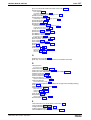
Contents I
Contents
1
System Overview
1.1
1-1
General Information ...................................................................................................................... 1-1
Overview of Drive Firmware..................................................................................................... 1-1
Terms, Basic Principles ........................................................................................................... 1-2
How to Use this Documentation............................................................................................... 1-7
1.2
Drive Controllers ......................................................................................................................... 1-10
Overview ................................................................................................................................ 1-10
Power Sections ...................................................................................................................... 1-11
Control Sections..................................................................................................................... 1-11
1.3
Motors and Measuring Systems ................................................................................................. 1-15
Supported Motors .................................................................................................................. 1-15
Supported Measuring Systems.............................................................................................. 1-15
1.4
Master Communication ............................................................................................................... 1-16
1.5
Overview of Functions................................................................................................................. 1-17
Supported Operating Modes.................................................................................................. 1-17
Drive Functions ...................................................................................................................... 1-17
1.6
Functional Packages................................................................................................................... 1-18
Overview ................................................................................................................................ 1-18
Base Packages ...................................................................................................................... 1-24
Alternative Functional Packages ........................................................................................... 1-27
Additive Functional Packages................................................................................................ 1-28
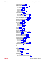
2
Important directions for use
2.1
2-1
Appropriate use............................................................................................................................. 2-1
Introduction .............................................................................................................................. 2-1
Areas of use and application.................................................................................................... 2-2
2.2
3
Inappropriate use .......................................................................................................................... 2-2
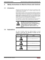
Safety Instructions for Electric Drives and Controls
3-1
3.1
Introduction ................................................................................................................................... 3-1
3.2
Explanations.................................................................................................................................. 3-1
3.3
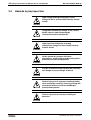
Hazards by Improper Use ............................................................................................................. 3-2
3.4
General Information ...................................................................................................................... 3-3
3.5
Protection Against Contact with Electrical Parts ........................................................................... 3-5
3.6
Protection Against Electric Shock by Protective Low Voltage (PELV) ......................................... 3-6
3.7
Protection Against Dangerous Movements .................................................................................. 3-7
3.8
Protection Against Magnetic and Electromagnetic Fields During Operation and
Mounting ....................................................................................................................................... 3-9
3.9
Protection Against Contact with Hot Parts .................................................................................. 3-10
DOK-INDRV*-MP*-02VRS**-FK01-EN-P
II Contents
MPH-02, MPB-02, MPD-02
3.10 Protection During Handling and Mounting .................................................................................. 3-10
3.11 Battery Safety.............................................................................................................................. 3-11
3.12 Protection Against Pressurized Systems .................................................................................... 3-11
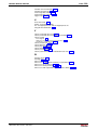
4
Master Communication
4.1
4-1
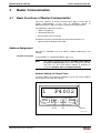
Basic Functions of Master Communication................................................................................... 4-1
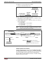
Address Assignment ................................................................................................................ 4-1
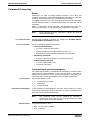
Command Processing.............................................................................................................. 4-3
Device Control (Status Machine) ............................................................................................. 4-5
4.2
Possibilities of Control/Additional Functions ............................................................................... 4-15
Configurable Signal Control Word ......................................................................................... 4-15
Configurable Signal Status Word........................................................................................... 4-17
4.3
Profile Types (with Field Bus Interfaces) .................................................................................... 4-19
Overview ................................................................................................................................ 4-19
I/O Mode ................................................................................................................................ 4-21
Freely Configurable Mode (Rexroth Profile Type) ................................................................. 4-24
Exemplary Configurations...................................................................................................... 4-28
4.4
SERCOS interface ...................................................................................................................... 4-32
Brief Description..................................................................................................................... 4-32
Commissioning the SERCOS interface ................................................................................. 4-34
Cyclic Data Transfer .............................................................................................................. 4-37
Transmission of Non-Cyclical Data........................................................................................ 4-39
Interface Errors and Diagnostic Possibilities ......................................................................... 4-39
Real-Time Control Bits and Real-Time Status Bits................................................................ 4-40
4.5
PROFIBUS-DP............................................................................................................................ 4-41
Brief Description..................................................................................................................... 4-41
Configuring the PROFIBUS-DP Slave................................................................................... 4-43
Parameter Channel in the Cyclic Channel (Device-Specific) ................................................ 4-46
DPV1 Parameter Communication (ProfiDrive) ...................................................................... 4-50
Cyclic Communication via Process Data Channel................................................................. 4-52
Monitoring Functions and Diagnostic Functions .................................................................... 4-53
4.6
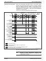
Parallel Interface ......................................................................................................................... 4-56
Brief Description..................................................................................................................... 4-56
Functional Description ........................................................................................................... 4-56
Notes on Commissioning/Parameterization........................................................................... 4-59
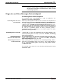
Diagnostic and Status Messages .......................................................................................... 4-62
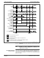
4.7
Analog Interface .......................................................................................................................... 4-63
Brief Description..................................................................................................................... 4-63
Functional Description ........................................................................................................... 4-66
Notes on Commissioning/Parameterization........................................................................... 4-68
Diagnostic and Status Messages .......................................................................................... 4-70
5
Motor, Mechanical Axis System, Measuring Systems
5.1
5-1
General Information on the Operation of Motors with IndraDrive ................................................. 5-1
Basics on the Motors to be Controlled..................................................................................... 5-1
Motor Temperature Monitoring ................................................................................................ 5-2
DOK-INDRV*-MP*-02VRS**-FK01-EN-P
MPH-02, MPB-02, MPD-02
Contents III
Motor Holding Brake ................................................................................................................ 5-5
5.2
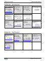
Rexroth Motors............................................................................................................................ 5-17
Basics on Rexroth Motors...................................................................................................... 5-17
Rexroth Housing Motors with Encoder Data Memory ........................................................... 5-19
Rexroth Housing Motors without Encoder Data Memory ...................................................... 5-21
Rexroth Kit Motors ................................................................................................................. 5-23
Rexroth Kit Motors, Synchronous .......................................................................................... 5-23
Rexroth Kit Motors, Asynchronous ........................................................................................ 5-25
5.3
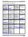
Third-Party Motors at IndraDrive Controllers .............................................................................. 5-25
General Information on Third-Party Motors ........................................................................... 5-25
Requirements on Third-Party Motors..................................................................................... 5-27
General Information on Controlling Third-Party Motors......................................................... 5-28
Determining the Motor Parameter Values ............................................................................. 5-31
Forms for Required Manufacturer-Side Output Data............................................................. 5-44
Forms for Parameter Values.................................................................................................. 5-47
Notes on Commissioning ....................................................................................................... 5-49
5.4
Measuring Systems .................................................................................................................... 5-50
Basics on Measuring Systems, Resolution............................................................................ 5-50
Monitoring the Measuring Systems ....................................................................................... 5-56
Absolute Measuring Systems ................................................................................................ 5-62
Relative Measuring Systems ................................................................................................. 5-66
5.5
Mechanical Axis System and Measuring Systems ..................................................................... 5-70
Measuring Systems for Motor and Axis Control, Arrangement ............................................. 5-70
Scaling of Physical Data ........................................................................................................ 5-77
6
Drive Control
6.1
6-1
Overview of Drive Control ............................................................................................................. 6-1
Open-Loop Axis Control (Open-Loop Operation) .................................................................... 6-1
Closed Loop Axis Control (Closed-Loop Operation) ............................................................... 6-2
6.2
Motor Control ................................................................................................................................ 6-2
General Information on Motor Control ..................................................................................... 6-2
Voltage-Controlled Operation (Open-Loop U/f Control) .......................................................... 6-3
Field-Oriented Closed-Loop Current Control ......................................................................... 6-10
Commutation Setting ............................................................................................................. 6-19
6.3
Axis Control (Open-Loop Operation) .......................................................................................... 6-34
Brief Description..................................................................................................................... 6-34
Functional Description ........................................................................................................... 6-36
Diagnostic and Status Messages .......................................................................................... 6-36
6.4
Axis Control (Closed-Loop Operation) ........................................................................................ 6-37
Overview ................................................................................................................................ 6-37
Automatic Setting of Axis Control .......................................................................................... 6-42
Velocity Loop (with Respective Filters).................................................................................. 6-50
Position Loop (with Respective Feedforward Functions) ...................................................... 6-60
6.5
Limitations ................................................................................................................................... 6-63
Overview ................................................................................................................................ 6-63
Current and Torque Limitation (Open-Loop).......................................................................... 6-64
DOK-INDRV*-MP*-02VRS**-FK01-EN-P
IV Contents
MPH-02, MPB-02, MPD-02
Current and Torque Limitation (Closed-Loop) ....................................................................... 6-64
Velocity Limitation .................................................................................................................. 6-71
Position Limitation/Travel Range Limit Switch....................................................................... 6-72
6.6
Power Supply .............................................................................................................................. 6-79
Possibilities of Power Supply for IndraDrive .......................................................................... 6-79
Functional Description ........................................................................................................... 6-83
Notes on Commissioning ....................................................................................................... 6-91
7
Operating Modes
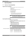
7.1
7-1
Overview of Operating Modes ...................................................................................................... 7-1
Supported Operating Modes.................................................................................................... 7-1
Operating Mode Handling ........................................................................................................ 7-1
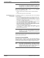
7.2
Torque/Force Control .................................................................................................................... 7-4
Brief Description....................................................................................................................... 7-4
Command Value Processing in Torque/Force Control ............................................................ 7-5
Current Loop ............................................................................................................................ 7-7
Diagnostic Messages and Monitoring Functions ..................................................................... 7-8
7.3
Velocity Control ............................................................................................................................. 7-8
Brief Description....................................................................................................................... 7-8
Command Value Adjustment in Velocity Control ................................................................... 7-10
Velocity Control Loop............................................................................................................. 7-13
Notes on Commissioning ....................................................................................................... 7-14
Diagnostic Messages and Monitoring Functions ................................................................... 7-15
7.4
Position Control with Cyclic Command Value Input.................................................................... 7-16
Brief Description..................................................................................................................... 7-16
Command Value Processing in Position Control ................................................................... 7-18
Position Controller.................................................................................................................. 7-19
Diagnostic Messages and Monitoring Functions ................................................................... 7-20
7.5
Drive-Internal Interpolation.......................................................................................................... 7-21
Brief Description..................................................................................................................... 7-21
Command Value Processing with Drive-Internal Interpolation .............................................. 7-23
Position Loop with Drive-Internal Interpolation ...................................................................... 7-24
Notes on Commissioning ....................................................................................................... 7-24
Diagnostic Messages and Monitoring Functions ................................................................... 7-26
7.6
Drive-Controlled Positioning ....................................................................................................... 7-28
Brief Description..................................................................................................................... 7-28
Command Value Processing with Drive-Controlled Positioning ............................................ 7-30
Position Loop with Drive-Controlled Positioning .................................................................... 7-35
Notes on Commissioning ....................................................................................................... 7-35
Diagnostic Messages and Monitoring Functions ................................................................... 7-38
7.7
Positioning Block Mode............................................................................................................... 7-40
Brief Description..................................................................................................................... 7-40
Command Value Processing in Positioning Block Mode....................................................... 7-43
Single-Block Processing ........................................................................................................ 7-43
Sequential Block Processing ................................................................................................. 7-60
Notes on Commissioning/Parameterization........................................................................... 7-71
DOK-INDRV*-MP*-02VRS**-FK01-EN-P
MPH-02, MPB-02, MPD-02
Contents V
Diagnostic and Status Messages, Acknowledgment............................................................. 7-73
7.8
Synchronization Modes............................................................................................................... 7-76
Basic Functions of the Synchronization Modes ..................................................................... 7-76
Velocity Synchronization with Real/Virtual Master Axis......................................................... 7-96
Phase Synchronization with Real/Virtual Master Axis ......................................................... 7-102
Electronic Cam Shaft with Real/Virtual Master Axis ............................................................ 7-112
8
Drive Functions
8.1
8-1
Drive Halt ...................................................................................................................................... 8-1
Brief Description....................................................................................................................... 8-1
Functional Description ............................................................................................................. 8-1
Notes on Commissioning ......................................................................................................... 8-3
8.2
Establishing the Position Data Reference..................................................................................... 8-4
General Information on Establishing the Position Data Reference ......................................... 8-4
Establishing Position Data Reference for Relative Measuring Systems ................................. 8-7
Establishing Position Data Reference for Absolute Measuring Systems .............................. 8-26
Shifting the Position Data Reference for Relative and Absolute Measuring Systems .......... 8-31
8.3
Error Reactions ........................................................................................................................... 8-35
Overview of Error Reactions .................................................................................................. 8-35
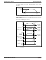
Best Possible Deceleration .................................................................................................... 8-36
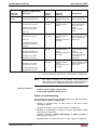
Package Reaction on Error.................................................................................................... 8-42
NC Reaction on Error............................................................................................................. 8-44
8.4
E-Stop Function .......................................................................................................................... 8-45
Brief Description..................................................................................................................... 8-45
Functional Description ........................................................................................................... 8-45
Notes on Commissioning ....................................................................................................... 8-46
Diagnostic and Status Messages .......................................................................................... 8-47
8.5
Compensation Functions/Corrections......................................................................................... 8-48
Friction Torque Compensation............................................................................................... 8-48
Encoder Correction ................................................................................................................ 8-50
Axis Error Correction.............................................................................................................. 8-53
Quadrant Error Correction ..................................................................................................... 8-68
8.6
Detecting the Marker Position..................................................................................................... 8-72
Brief Description..................................................................................................................... 8-72
Functional Description ........................................................................................................... 8-72
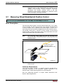
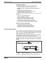
8.7
Measuring Wheel Mode/Hybrid Position Control ........................................................................ 8-73
Brief Description..................................................................................................................... 8-73
Functional Description ........................................................................................................... 8-74
Notes on Commissioning ....................................................................................................... 8-77
8.8
Positive Stop Drive Procedure .................................................................................................... 8-78
Brief Description..................................................................................................................... 8-78
Functional Description ........................................................................................................... 8-79
Notes on Commissioning ....................................................................................................... 8-80
8.9
Spindle Positioning...................................................................................................................... 8-80
Brief Description..................................................................................................................... 8-80
Functional Description ........................................................................................................... 8-81
DOK-INDRV*-MP*-02VRS**-FK01-EN-P
VI Contents
MPH-02, MPB-02, MPD-02
Notes on Commissioning ....................................................................................................... 8-84
Diagnostic Messages............................................................................................................. 8-85
8.10 Rexroth IndraMotion MLD-S (Drive-Integrated PLC).................................................................. 8-86
Brief Description..................................................................................................................... 8-86
Notes on Installation/System Configuration........................................................................... 8-88
Overview of Available Libraries.............................................................................................. 8-89
8.11 Drive-Integrated Safety Technology ........................................................................................... 8-91
Safety Related Starting Lockout ............................................................................................ 8-91
Integrated Safety Functions ................................................................................................... 8-92
9
Extended Drive Functions
9.1
9-1
Probe Function.............................................................................................................................. 9-1
Brief Description....................................................................................................................... 9-1
Functional Description ............................................................................................................. 9-2
Notes on Commissioning ......................................................................................................... 9-6
9.2
Measuring Encoder ....................................................................................................................... 9-8
Brief Description....................................................................................................................... 9-8
Functional Description ........................................................................................................... 9-10
Notes on Commissioning ....................................................................................................... 9-16
9.3
Encoder Emulation...................................................................................................................... 9-18
Brief Description..................................................................................................................... 9-18
Basic Information on the Function ......................................................................................... 9-20
Incremental Encoder Emulation............................................................................................. 9-21
Absolute Encoder Emulation.................................................................................................. 9-24
Notes on Commissioning ....................................................................................................... 9-26
Diagnostic and Status Messages .......................................................................................... 9-28
9.4
Analog Inputs .............................................................................................................................. 9-28
Brief Description..................................................................................................................... 9-28
Functional Description ........................................................................................................... 9-30
Notes on Commissioning ....................................................................................................... 9-34
Diagnostic Messages and Status Displays............................................................................ 9-35
9.5
Analog Outputs ........................................................................................................................... 9-36
Brief Description..................................................................................................................... 9-36
Functional Description ........................................................................................................... 9-37
Notes on Commissioning ....................................................................................................... 9-41
9.6
Digital Inputs/Outputs.................................................................................................................. 9-42
Brief Description..................................................................................................................... 9-42
Notes on Commissioning for Digital I/Os of Control Section ................................................. 9-44
Notes on Commissioning for Digital I/Os of Optional Module MD1 ....................................... 9-49
Diagnostic Messages and Status Displays............................................................................ 9-53
Hardware Requirements ........................................................................................................ 9-54
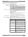
10 Handling, Diagnostic and Service Functions
10-1
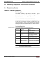
10.1 Parameters, Basics ..................................................................................................................... 10-1
Properties, Features of Parameters....................................................................................... 10-1
Loading, Storing and Saving Parameters .............................................................................. 10-3
DOK-INDRV*-MP*-02VRS**-FK01-EN-P
MPH-02, MPB-02, MPD-02
Contents VII
IDN Lists of Parameters....................................................................................................... 10-11
Using a Password ................................................................................................................ 10-13
10.2 Device Configuration................................................................................................................. 10-17
Controller Design ................................................................................................................. 10-17
Circuit Board Code............................................................................................................... 10-18
Hours-Run Meter ................................................................................................................. 10-19
Error Memory (Power Section and Control Section) ........................................................... 10-20
10.3 Diagnostic System .................................................................................................................... 10-21
Coded Diagnostic Drive Messages...................................................................................... 10-21
Status Classes, Status Displays, Control Parameters......................................................... 10-24
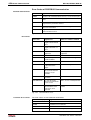
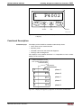
10.4 Control Panel of the IndraDrive Controllers .............................................................................. 10-30
Brief Description................................................................................................................... 10-30
Functional Description ......................................................................................................... 10-31
Notes on Commissioning ..................................................................................................... 10-37
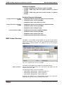
10.5 MultiMediaCard (MMC) ............................................................................................................. 10-37
Brief Description................................................................................................................... 10-37
MMC Folder Structure.......................................................................................................... 10-38
Firmware Update with MMC ................................................................................................ 10-39
Notes on Commissioning ..................................................................................................... 10-41
10.6 Firmware Update....................................................................................................................... 10-43
General Information ............................................................................................................. 10-43
Firmware Update with "Dolfi" Program ................................................................................ 10-43
Firmware Update with MultiMediaCard (MMC).................................................................... 10-43
10.7 Notes on How to Replace the Devices ..................................................................................... 10-44
Supply Units ......................................................................................................................... 10-44
Drive Controllers .................................................................................................................. 10-44
10.8 Enabling of Functional Packages.............................................................................................. 10-49
Brief Description................................................................................................................... 10-49
Functional Description ......................................................................................................... 10-50
Notes on Commissioning ..................................................................................................... 10-53
Monitoring the Enabling of Functional Packages ................................................................ 10-54
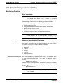
10.9 Extended Diagnostic Possibilities ............................................................................................. 10-55
Monitoring Function ............................................................................................................. 10-55
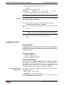
Logbook Function ................................................................................................................ 10-56
Patch Function ..................................................................................................................... 10-57
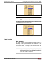
10.10 Oscilloscope Function ............................................................................................................... 10-62
Brief Description................................................................................................................... 10-62
General Information on the Oscilloscope Function.............................................................. 10-64
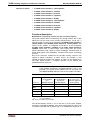
Trigger Function................................................................................................................... 10-66
Synchronizing the Measuring Signals of Several Axes ....................................................... 10-70
Parameterizing the Oscilloscope Function .......................................................................... 10-72
Diagnostic and Status Messages ........................................................................................ 10-73
DOK-INDRV*-MP*-02VRS**-FK01-EN-P
VIII Contents
MPH-02, MPB-02, MPD-02
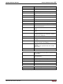
10.11 Serial Communication ............................................................................................................... 10-74
Overview of Serial Communication...................................................................................... 10-74
Functional Principle Independent of Protocol ...................................................................... 10-76
Communication with ASCII Protocol.................................................................................... 10-81
Communication with SIS Protocol ....................................................................................... 10-91
11 Commissioning
11-1
11.1 Commissioning Motors................................................................................................................ 11-1
Checking the Installation/Assembly ....................................................................................... 11-1
Initial Commissioning/Serial Commissioning ......................................................................... 11-1
Initial Start in "Easy Startup" Mode ........................................................................................ 11-4
Initial Start with DriveTop Commissioning Tool ................................................................... 11-10
11.2 Commissioning Machine Axes.................................................................................................. 11-14
Overview and Practical Tips ................................................................................................ 11-14
12 Index
12-1
13 Service & Support
13-1
13.1 Helpdesk ..................................................................................................................................... 13-1
13.2 Service-Hotline............................................................................................................................ 13-1
13.3 Internet ........................................................................................................................................ 13-1
13.4 Vor der Kontaktaufnahme... - Before contacting us.................................................................... 13-1
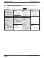
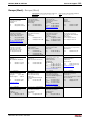
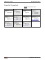
13.5 Kundenbetreuungsstellen - Sales & Service Facilities ............................................................... 13-2
DOK-INDRV*-MP*-02VRS**-FK01-EN-P
System Overview 1-1
MPH-02, MPB-02, MPD-02
1
System Overview
1.1
General Information
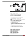
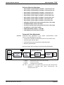
Overview of Drive Firmware
Firmware Variants
For the IndraDrive range, there are different application-related firmware
variants available that are characterized by their scope of functions and
their performance:
• MTH: Drives for Machine Tool Applications with SERCOS interface
(Advanced Performance and Functionality)
• MPX: Drives for General Automation (Incl. Machine Tool Applications)
with SERCOS interface, Profibus, as well as Parallel and Analog
Interface
(the variants of design are MPH, MPB and MPD; see below)
Note:
The first two letters of the firmware designation identify the
application and profile of the firmware:
• MT: "Machine Tool" → Drives for Machine Tool
Applications with SERCOS interface
(drive profile according to SERCOS)
• MP: "Multi Purpose" → Drives for General Automation
(Incl. Machine Tool Applications) with
SERCOS interface, Profibus, as well as Parallel and
Analog Interface
(drive profile according to SERCOS)
The third letter of the firmware designation identifies the
hardware and performance and functionality of the firmware
(X includes H, B and D):
• H: single-axis firmware with advanced performance and
functionality
• B: single-axis firmware with basic performance and
functionality
• D: double-axis firmware with basic performance and
functionality
This documentation describes the functionality of the following firmware
variants:
• FWA-INDRV*-MPH-02VRS-MS
• FWA-INDRV*-MPB-02VRS-MS
• FWA-INDRV*-MPD-02VRS-MS
The "DriveTop" commissioning tool in version DTOP16 is available for
commissioning these firmware variants.
DOK-INDRV*-MP*-02VRS**-FK01-EN-P
1-2 System Overview
MPH-02, MPB-02, MPD-02
Organization of the Firmware
For application-specific definition of drive functionality the firmware
functions are divided into different "functional packages". There are a
generally available basic package and various additional functional
packages (e.g. drive-integrated safety technology, IndraMotion MLD-S)
that can be optionally activated.
Note:
The scope of functions of the functional packages and their
possible combinations are described in the section "Functional
Packages" in the same chapter.
Terms, Basic Principles
Parameters
Communication between master and drive takes place, with a few
exceptions, by means of parameters.
Parameters are used for:
• determining the configuration
• parameterizing the control loop
• triggering and controlling drive functions and commands
• transmitting command values and actual values (according to
requirements, cyclically or acyclically)
All operating data are mapped to parameters!
The operating data stored in parameters can be identified by means of
the IDN. They can be read and transferred, if required. The user write
access to parameters depends on the properties of the respective
parameter and the current communication phase. Specific parameter
values (operating data) are checked for validity by the drive firmware.
Data Storage and Parameter Handling
Data Memory
Several non-volatile data memories are available in an IndraDrive device:
• in the controller
• in the motor encoder (depending on motor type)
• as a MultiMediaCard (MMC), optional
In addition, a volatile data memory (working memory) is available in the
controller.
Condition As Supplied
Condition as supplied of the Rexroth drive components:
• The controller memory contains the drive firmware and the controllerspecific parameter values.
• The motor encoder memory contains the encoder-specific and,
depending on the motor type, the motor-specific parameter values.
• The MMC contains the drive firmware and the basic parameter sets.
Storing the Application-Specific
Parameter Values
The application-specific parameter values are stored in the controller. Due
to the limited number of writing cycles of non-volatile storage media,
application-specific parameter values can be stored in the working
memory (volatile memory), too.
DOK-INDRV*-MP*-02VRS**-FK01-EN-P
System Overview 1-3
MPH-02, MPB-02, MPD-02
Saving Parameter Values
Saving application-specific parameter values is required in the following
cases:
• after initial commissioning of the machine axis or the motor
• before replacing the controller for servicing (if possible)
Application-specific parameter values can be saved via:
• MMC → copying the parameter values by command
• "DriveTop" commissioning tool → saving the parameter values on
external data carrier
• control master → saving the parameter values on master-side data
carrier
Parameter IDN Lists
Loading Parameter Values
The drive supports master-side saving of parameter values by listing
parameter identification numbers (IDNs). Using these lists guarantees
complete storage of the application-specific parameter values. It is also
possible to determine IDN lists defined by the customer.
Loading parameter values is required in the following cases:
• initial commissioning of the motor (loading basic parameter values and
motor-specific parameter values)
• serial commissioning of machine axes at series machines (loading the
values saved after initial commissioning)
• reestablishing a defined original status (repeated loading of the values
saved after initial commissioning)
• replacing the controller for servicing (loading the current parameter
values saved before servicing)
Possibilities of loading parameter values to the controller:
• motor encoder data memory → loading the parameter values by
command or via the control panel during initial motor commissioning
• MMC → loading the parameter values by command
• "DriveTop" commissioning tool → loading the parameter values from
external data carrier
• control master → loading the parameter values from master-side data
carrier
Checksum of Parameter Values
By means of checksum comparison, the control master can determine
whether the values of the application-specific parameter values currently
active in the drive correspond to the values saved on the master side.
Password
IndraDrive controllers provide the possibility to protect parameter values
against accidental or unauthorized change by means of a password. With
regard to write protection, there are 3 groups of parameters that can be
written:
• Parameters that are write-protected as a standard, such as motor
parameters, hardware code parameters, encoder parameters, error
memory etc. ("administration parameters"). The values of these
parameters guarantee correct function and performance of the drive.
• Parameters the customer can combine in groups and protect them
with a so-called customer password. This allows protecting parameter
values, that are used for adjusting the drive to the axis, after having
determined them.
• All other parameters that can be written and are not contained in the
above-mentioned groups. They are not write-protected.
DOK-INDRV*-MP*-02VRS**-FK01-EN-P
1-4 System Overview
Kinds of Passwords
MPH-02, MPB-02, MPD-02
The drive firmware allows activating and deactivating the write protection
for parameter values by means of three hierarchically different
passwords:
• Customer password
The parameter values of a parameter group combined by the
customer can be protected.
• Control password
Parameters protected by a customer password can be written;
"administration parameters" remain write-protected.
• Master password
All parameters that can be written, including "administration
parameters" and parameters protected by a customer password, can
be changed.
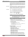
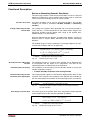
Commands
Commands are used to activate and control complex functions or
monitoring features in the drive. The higher-level master can start,
interrupt or clear commands.
Each command is assigned to a parameter by means of which the
execution of the command can be controlled. During the execution of the
command the display of the control panel reads "Cx", "C" representing the
diagnostic command message and "x" representing the number of the
command.
Note:
Each command that was started must be actively cleared
again.
All commands available in the drive are stored in the S-0-0025, IDN-list
of all procedure commands parameter.
Kinds of Commands
There are 3 different kinds of commands:
• Drive control commands
• can cause automatic drive motion,
• can be started only when drive enable has been set,
• deactivate the active operating mode during its execution.
• Monitoring commands
• activate or deactivate monitors or functions in the drive.
• Administration commands
• carry out administration tasks,
• cannot be interrupted.
See also "Command Processing" in chapter "Master Communication"
DOK-INDRV*-MP*-02VRS**-FK01-EN-P
System Overview 1-5
MPH-02, MPB-02, MPD-02
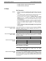
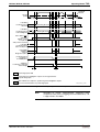
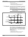
Operating Modes
The selection of operating modes defines which command values will be
processed in which way, in order to lead to the desired drive motion. The
operating mode does not determine how these command values are
transmitted from the master to the slave.
One of the four operating modes defined in the parameters
S-0-0032 to S-0-0035 is always active when the following conditions have
been fulfilled:
• control section and power section are ready for operation
• drive enable signal sees a positive edge
• drive follows command value
• "Drive Halt" function has not been activated
• no drive control command is active
• no error reaction is carried out
The display of the control panel reads "AF" when an operating mode was
activated.
Note:
All implemented operating modes are stored in the S-0-0292,
List of all operating modes parameter.
See also chapter "Operating Modes"
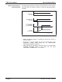
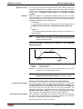
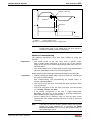
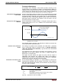
Warnings
Depending on the active operating mode and the parameter settings,
many monitoring functions are carried out. If a status is detected that still
allows correct operation but in case this status persists will cause an error
to occur and therefore cause the drive to be automatically switched off,
the drive firmware generates a warning message.
Note:
Warning Classes
Warnings do not cause automatic shutdown (exception: fatal
warning).
Warnings are classified in different warning classes which determine
whether the drive, when the warning is generated, carries out an
automatic reaction or not.
Note:
The warning class can be recognized by the diagnostic
message.
The following classes of warnings are distinguished:
• without drive reaction
E7xxx
→ diagnostic message numbers E1xxx to
• with drive reaction
→ diagnostic message number E8xxx
Note:
DOK-INDRV*-MP*-02VRS**-FK01-EN-P
Warnings cannot be cleared. They persist until the condition
that activated the warning is no longer fulfilled.
1-6 System Overview
MPH-02, MPB-02, MPD-02
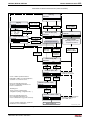
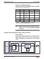
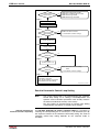
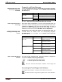
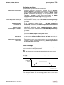
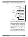
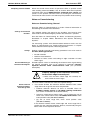
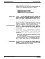
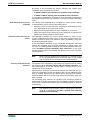
Errors
Depending on the active operating mode and the parameter settings,
many monitoring functions are carried out. If a status is detected that
affects or prevents correct operation the drive firmware generates an
error message.
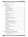
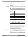
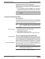
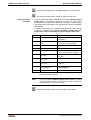
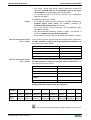
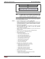
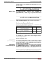
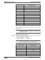
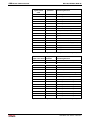
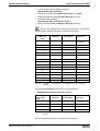
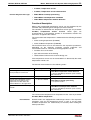
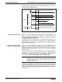
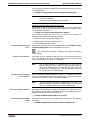
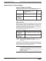
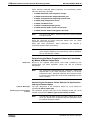
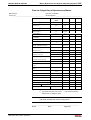
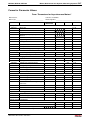
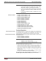
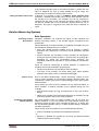
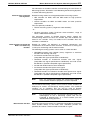
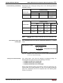
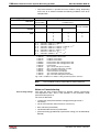
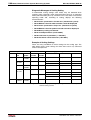
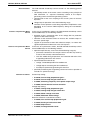
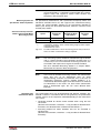
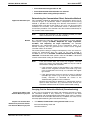
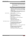
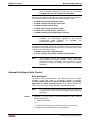
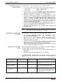
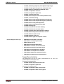
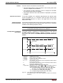
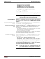
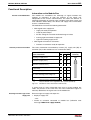
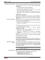
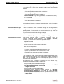
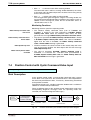
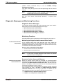
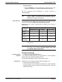
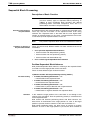
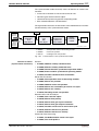
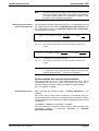
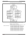
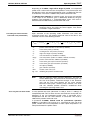
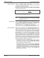
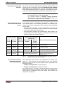
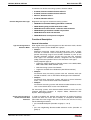
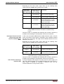
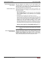
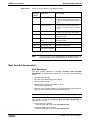
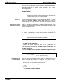
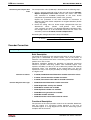
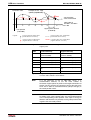
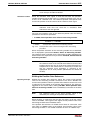
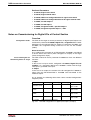
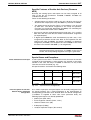
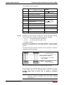
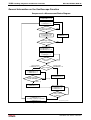
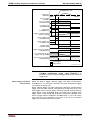
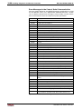
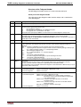
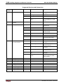
Error Classes
Errors are classified in different error classes. There are 6 error classes
with different drive error reactions.
Note:
Error Reactions of the Drive
The error class can be recognized by the diagnostic message
number.
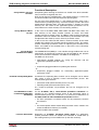
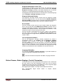
Diagnostic message
number
Error class
F2xxx
non-fatal error
F3xxx
non-fatal safety technology error
F4xxx
interface error
F6xxx
travel range error
F7xxx
safety technology error
F8xxx
fatal error
F9xxx
fatal system error
E-xxxx
fatal system error "processor exception"
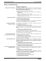
Fig. 1-1:
Overview of error classes
Note:
Apart from the mentioned error classes that can occur during
operation, errors can occur when the devices are booted and
during firmware download. These errors are not displayed at
the control panel with a diagnostic message number of the
"Fxxxx" pattern, but with a short text. Boot errors and firmware
download errors are separately described in the
documentation "Troubleshooting Guide".
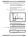
If the drive controller is in control and an error status is detected, the
execution of a drive error reaction is automatically started. The diagnostic
message number "Fxxxx" flashes on the display of the control panel.
The drive reaction in the case of interface errors and non-fatal errors is
determined in parameter P-0-0119, Best possible deceleration At the
end of each error reaction, the drive is torque-free.
See also "Error Reactions" in chapter "Drive Functions"
Clearing Error Messages
Error messages are not cleared automatically but by the following action:
• activating the S-0-0099, C0500 Reset class 1 diagnostics command
- or • actuating the "Esc" button on the standard control panel
If the error status persists the error message is immediately generated
again.
DOK-INDRV*-MP*-02VRS**-FK01-EN-P
System Overview 1-7
MPH-02, MPB-02, MPD-02
Clearing Error Messages when
Drive Enable Was Set
If a drive error occurs while operating with drive enable having been set,
the drive carries out an error reaction. The drive automatically deactivates
itself at the end of each error reaction; in other words, the output stage is
switched off and the drive switches from an energized to a de-energized
state.
To reactivate the drive:
• clear the error message and
• input a positive edge for drive enable again.
Error Memory
The diagnostic message numbers of occurring errors are written to an
error memory. This memory contains the diagnostic message numbers of
the last 50 errors that occurred and the time when they occurred. Errors
caused by a shutdown of the control voltage (e.g. F8070 +24Volt DC
error) are not stored in the error memory.
The diagnostic message numbers in the error memory are mapped to the
P-0-0192, Diagnostic numbers of error memory parameter and can be
displayed by means of the control panel. By means of the "DriveTop"
commissioning tool it is possible to display the diagnostic message
numbers and the respective times at which the errors occurred.
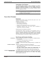
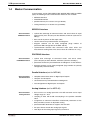
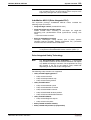
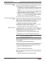
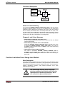
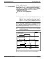
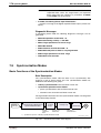
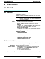
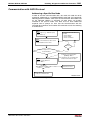
How to Use this Documentation
Structure of the Functional Description
The functional descriptions of the IndraDrive firmware are divided into
fixed chapters. The individual subjects of the firmware description are
assigned to these chapters according to their content.
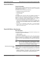
The description of the respective firmware functionality is basically divided
into the following sections:
• Brief Description
• Functional Description
• Notes on Commissioning
• Diagnostic and Status Messages, Monitoring Functions
Within one subject these sections are always contained in the mentioned
order, but for practical and formal reasons they are not always existing or
may have a different title.
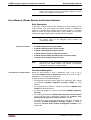
Brief Description
The brief description contains an overview of the firmware function or the
subject of the section. The brief description can contain, for example,
general basics, the most important features of the function, overviews and
examples of application. At the end of the brief description you can find,
where possible and reasonable, a list of the parameters and diagnostic
messages that are associated with this functions.
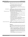
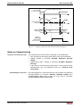
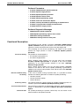
Functional Description
The section "Functional Description" explains the operating principle of
the respective drive function in an application-oriented way. The relevant
parameters of this function are described with regard to their settings and
effects. The parameter configuration is only explained in detail where this
is necessary for the description of the function. As a basic principle, the
functional description contains references to the separate documentations
for parameters and diagnostic messages.
DOK-INDRV*-MP*-02VRS**-FK01-EN-P
1-8 System Overview
MPH-02, MPB-02, MPD-02
The detailed description of the parameters, their function and
structure is contained in the separate documentation "Rexroth IndraDrive,
Parameter Description".
The detailed description of the diagnostic messages, their causes
and remedies is contained in the separate documentation
"Rexroth IndraDrive, Troubleshooting Guide" (description of diagnostic
messages).
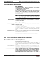
Notes on Commissioning
The section "Notes on Commissioning" or "Notes on Parameterization"
provides the user with the steps required for commissioning the function,
similar to a checklist. The necessary parameter settings are described in
compact form and, if necessary, instructions are given for activating the
function and the diagnostic messages of the immediate functional
sequence are mentioned.
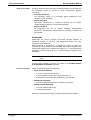
Diagnostic and Status
Messages, Monitoring Functions
The section "Diagnostic and Status Messages" (also "Monitoring
Functions", if necessary) summarizes the diagnostic messages and
possible status displays available for the respective function and
describes them briefly. If there are function-specific monitoring functions,
they are also described in this section.
The detailed description of the diagnostic messages, their causes
and remedies is contained in the separate documentation
"Rexroth IndraDrive, Troubleshooting Guide" (description of diagnostic
messages).
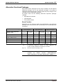
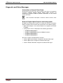
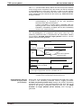
Markers and Terms
The complete functionality of the IndraDrive firmware is divided into
functional packages (base packages and optional expansion packages).
The scope of the available functions does not only depend on the
hardware design, but in the majority of cases also on the variant and
characteristic of the firmware.
The descriptions of the master communication, the drive functions and
the operating modes have a marker containing information on the
availability of this functionality in the respective functional package of the
firmware, e.g.:
Base package of all variants
Terms
The application-specific scalability of the hardware and firmware provides
a multitude of possibilities. For detailed information the following terms
are used in the Functional Description:
• firmware range
e.g. IndraDrive
• firmware design
single-axis, double-axis (multi-axis)
• firmware variant
e.g. MPH, MPB, MPD
• firmware version
e.g. MPH-02VRS
• firmware characteristic
open-loop/closed-loop
• Firmware performance
basic/advanced
• firmware type
complete firmware type designation
DOK-INDRV*-MP*-02VRS**-FK01-EN-P
System Overview 1-9
MPH-02, MPB-02, MPD-02
Note:
In many cases the availability of certain functions within the
functional packages also depends on design, variant and
characteristic of the firmware.
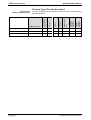
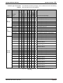
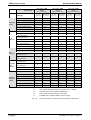
The exact dependence of the firmware functions on the design
of hardware and firmware can be seen in the tables in section
"Functional Packages".
Cross References
Many basic subfunctions of the firmware as well as necessary settings
and definitions are of multiple use within the overall functionality or have
an effect on neighboring areas of the drive functionality. Such
subfunctions normally are described only once. Descriptions that are part
of
other
IndraDrive
documentations
(Parameter
Description,
Troubleshooting Guide, Project Planning Manuals ...) are only repeated in
detail in exceptional cases. Cross references indicate the source for more
detailed information.
Cross references to other sections or documentations follow this scheme:
• references to sections in the same chapter by indicating title without
chapter
• references to sections in a different chapter by indicating title of
section and chapter
•
References to another documentation are additionally marked
by the "info icon" unless they are contained in a note or put in
parentheses.
Further Documentations
Firmware documentation:
• Parameter Description
DOK-INDRV*-GEN-**VRS**-PA**-EN-P; part no. R911297317
• Troubleshooting Guide (description of diagnostic messages)
DOK-INDRV*-GEN-**VRS**-WA**-EN-P; part no. R911297319
• Firmware Version Notes
DOK-INDRV*-MPX-02VRS**-FV**-EN-P; part no. R911297315
• Drive-integrated safety technology
DOK-INDRV*-SI*-**VRS**-FK**-EN-P; part no. R911297838
• IndraMotion MLD-S (drive-integrated PLC)
DOK-INDRV*-MLD-S*VRS**-AW**-EN-P; part no. R911306084
Hardware documentation (Project Planning Manuals):
• Power sections
DOK-INDRV*-HMS+HMD****-PR**-EN-P; part no. R911295014
• Control sections
DOK-INDRV*-CSH********-PR**-EN-P; part no. R911295012
• IndraDrive M supply units
DOK-INDRV*-HMV-*******-PR**-EN-P; part no. R911299229
DOK-INDRV*-MP*-02VRS**-FK01-EN-P
1-10 System Overview
1.2
MPH-02, MPB-02, MPD-02
Drive Controllers
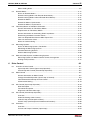
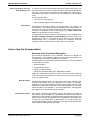
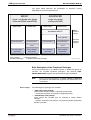
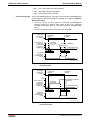
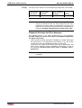
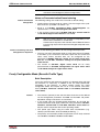
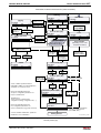
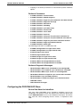
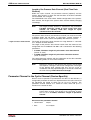
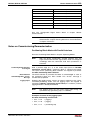
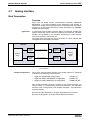
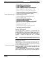
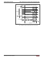
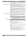
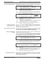
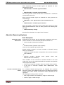
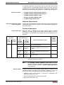
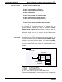
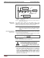
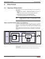
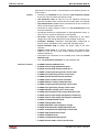
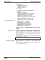
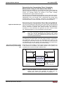
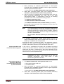
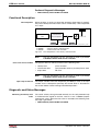
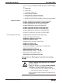
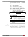
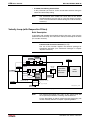
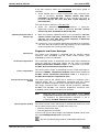
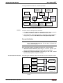
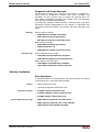
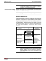
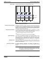
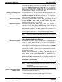
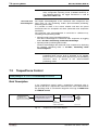
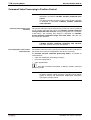
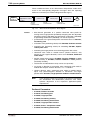
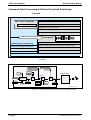
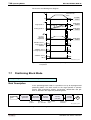
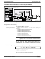
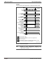
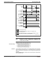
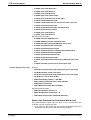
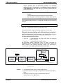
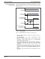
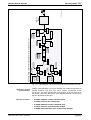
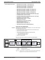
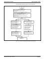
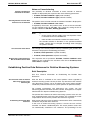
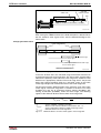
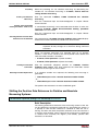
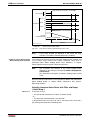
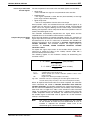
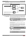
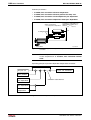
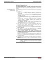
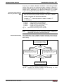
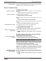
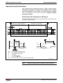
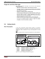
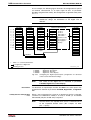
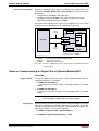
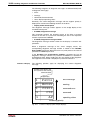
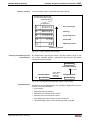
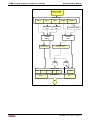
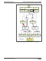
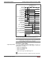
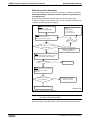
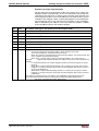
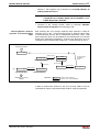
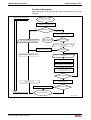
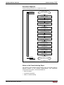
Overview
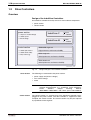
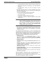
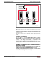
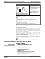
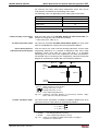
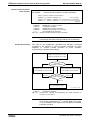
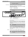
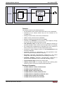
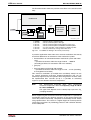
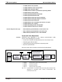
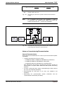
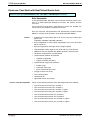
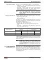
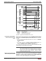
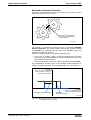
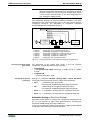
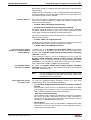
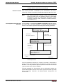
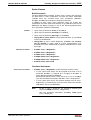
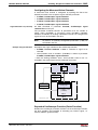
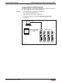
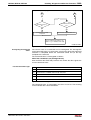
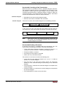
Design of the IndraDrive Controllers
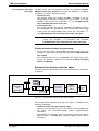
An IndraDrive controller basically consists of two hardware components:
• power section
• control section
power section
Compact
IndraDrive C
• compact or modular design
1 ... 110 kW
• scalable power
• uniform design
IndraDrive M
control section
• scalable performance
Modular
1 ... 120 kW
ADVANCED single-axis
high performance and interface flexibility
• scalable functionality
BASIC single-axis
limited performance and interface flexibility
• safety technology
BASIC double-axis
limited performance and interface flexibility
DF000108v01_en.fh7
Fig. 1-2:
Power Section
Design and types of the IndraDrive controllers
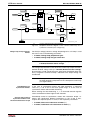
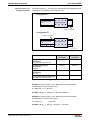
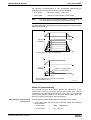
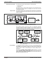
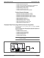
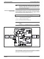
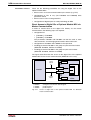
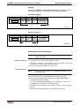
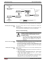
The following are connected to the power section:
• power supply unit (DC bus voltage)
• 24 V control voltage
• motor
Note:
Control Section
Each of the two types of the control section is described in the
separate documentation; e.g. "IndraDrive Drive Controllers,
Power
Sections,
Project
Planning
Manual"
(DOK-INDRV*-HMS+HMD****-PR**-EN-P; part no. R911295014).
The control section is a separate part of the IndraDrive controller and is
plugged in the power section. The drive controller is supplied ex works
complete with control section. The control section may only be replaced
by a qualified service engineer.
DOK-INDRV*-MP*-02VRS**-FK01-EN-P
System Overview 1-11
MPH-02, MPB-02, MPD-02
Note:
The available control sections are described in the separate
documentation "IndraDrive Drive Controllers, Control Sections,
Project Planning Manual" (DOK-INDRV*-CSH********-PR**EN-P; part no. T911295012).
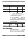
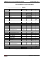
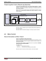
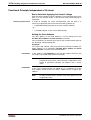
Power Sections
The following power sections can be operated with this firmware:
IndraDrive M
Single-Axis
The following single-axis power sections can be operated with the FWAINDRV*-MPH02VRS and FWA-INDRV*-MPB02VRS firmware:
• HMS01.1N-W020
• HMS01.1N-W036
• HMS01.1N-W054
• HMS01.1N-W070
• HMS01.1N-W150
• HMS01.1N-W210
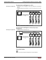
Double-Axis
The following double-axis power sections can only be operated with the
FWA-INDRV*-MPD02VRS firmware:
• HMD01.1N-W012
• HMD01.1N-W020
• HMD01.1N-W036
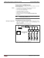
IndraDrive C
The following single-axis converters can be operated with the FWAINDRV*-MPH02VRS and FWA-INDRV*-MPB02VRS firmware:
300mm Type
• HCS02.1-W0012
• HCS02.1-W0028
• HCS02.1-W0054
• HCS02.1-W0070
400mm Type
• HCS03.1-W0070
• HCS03.1-W0100
• HCS03.1-W0150
• HCS03.1-W0210
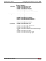
Control Sections
The following control sections can be operated with the FWA-INDRV*MP*-02VRS firmware:
• ADVANCED (single-axis; type designation CSH01.1C-...)
• BASIC OPENLOOP (single-axis; type designation CSB01.1N-FC-...)
• BASIC SERCOS (single-axis; type designation CSB01.1N-SE-...)
• BASIC PROFIBUS (single-axis; type designation CSB01.1N-PB-...)
• BASIC ANALOG (single-axis; type designation CSB01.1N-AN-...)
• BASIC UNIVERSAL (single-axis; type designation CSB01.1C-...)
• BASIC UNIVERSAL double-axis (type designation CDB01.1C-...)
DOK-INDRV*-MP*-02VRS**-FK01-EN-P
1-12 System Overview
MPH-02, MPB-02, MPD-02
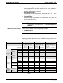
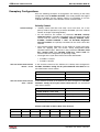
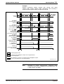
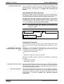
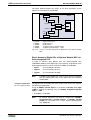
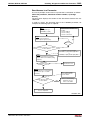
Control Section Configuration
The parts of the type designations listed below describe the differences
with regard to the possibilities of configuration. The following
abbreviations are used:
Master communication:
• SE
→ SERCOS interface
• PB
→ PROFIBUS-DP
• PL
→ parallel interface
• AN
→ analog interface
• FC
→ FC special
Standard optional modules:
• NNN → not equipped
• EN1 → encoder interface for HSF, resolver
• EN2 → encoder interface for EnDat, 1Vpp sine and TTL signals
• ENS → encoder interface for MSK motors and HIPERFACE
encoders
• MA1 → analog I/Os
• MD1 → digital I/Os
• MEM → encoder emulator
Safety option:
• NN
→ not equipped
• L1
→ starting lockout
• S1
→ module for safety technology
Note:
The basic structure of the type codes of the individual types of
IndraDrive control sections is described in the separate
documentation "IndraDrive Drive Controllers, Control Sections,
Project Planning Manual" (DOK-INDRV*-CSH********-PR**EN-P; part no. T911295012).
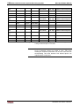
Supported Control Section Configurations
Note:
The lists below contain the theoretically
configurations of the control sections.
possible
Your sales representative will help you with the current status
of available control section types.
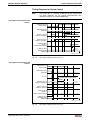
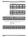
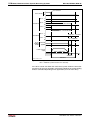
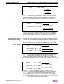
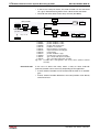
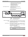
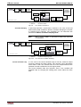
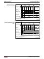
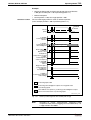
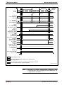
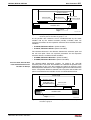
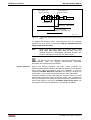
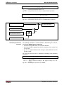
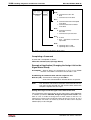
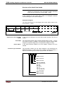
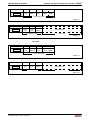
ADVANCED Single-Axis
(CSH01.1)
The firmware FWA-INDRV*-MPH-02VRS for configurable ADVANCED
single-axis control sections supports control sections with the following
type designations:
1)
2)
3)
4)
5)
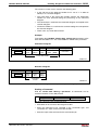
• CSH01.1C-xx -xxx -xxx -xxx -xx -S-NN-FW
DOK-INDRV*-MP*-02VRS**-FK01-EN-P
System Overview 1-13
MPH-02, MPB-02, MPD-02
Possible types:
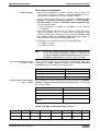
BASIC Single-Axis
(CSB01.1)
1)
… Master communication:
SE
→ SERCOS interface
PB → PROFIBUS-DP
PL
→ parallel interface
AN → analog interface
2)
… optional module 1 (X4):
NNN → not equipped
EN1 → encoder interface for HSF/resolver
EN2 → encoder interface for EnDat/1Vpp sine/TTL signals
ENS → encoder interface for Rexroth standard/HIPERFACE/1Vpp
MA1 → analog I/Os
MEM → encoder emulator
3)
… optional module 2 (X8):
NNN → not equipped
EN1 → encoder interface for HSF/resolver
EN2 → encoder interface for EnDat/1Vpp sine/TTL signals
ENS → encoder interface for Rexroth standard/HIPERFACE/1Vpp
MA1 → analog I/Os
MEM → encoder emulator
4)
… optional module 3, technology slot (X10):
NNN → not equipped
EN1 → encoder interface for HSF/resolver
EN2 → encoder interface for EnDat/1Vpp sine/TTL signals
ENS → encoder interface for Rexroth standard/HIPERFACE/1Vpp
MA1 → analog I/Os
MD1 → digital I/Os
MEM → encoder emulator
5)
… safety option (X41):
NN → not equipped
L1
→ starting lockout
S1
→ module for safety technology
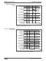
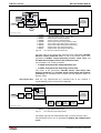
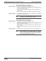
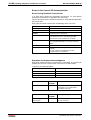
The firmware FWA-INDRV*-MPB-02VRS for BASIC single-axis control
sections supports standard control sections (not configurable) with the
following type designations:
• CSB01.1N-FC-NNN-NNN-NN-S-NN-FW
→ BASIC OPENLOOP
• CSB01.1N-SE-ENS-NNN-NN-S-NN-FW
→ BASIC SERCOS
• CSB01.1N-PB-ENS-NNN-NN-S-NN-FW
→ BASIC PROFIBUS
• CSB01.1N-AN-ENS-NNN-NN-S-NN-FW
→ BASIC ANALOG
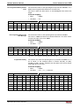
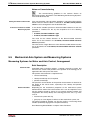
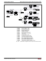
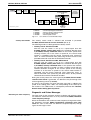
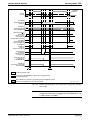
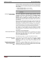
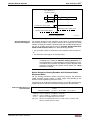
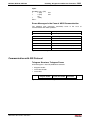
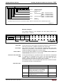
This firmware additionally supports configurable BASIC single-axis
control sections with the following type designations:
1)
2)
3)
5)
• CSB01.1C-xx -xxx -xxx -xx -S-NN-FW
→ BASIC UNIVERSAL (single-axis, configurable)
Possible types of BASIC UNIVERSAL (single-axis):
DOK-INDRV*-MP*-02VRS**-FK01-EN-P
1)
… Master communication:
SE
→ SERCOS interface
PB → PROFIBUS-DP
PL
→ parallel interface
AN → analog interface
2)
… encoder interface "on board" (X4):
ENS → encoder interface for Rexroth standard/HIPERFACE/1Vpp
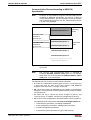
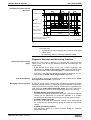
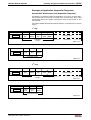
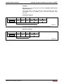
1-14 System Overview
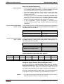
BASIC Double-Axis
(CDB01.1)
MPH-02, MPB-02, MPD-02
3)
… optional module 2 (X8):
NNN → not equipped
EN1 → encoder interface for HSF/resolver
EN2 → encoder interface for EnDat/1Vpp sine/TTL signals
ENS → encoder interface for Rexroth standard/HIPERFACE/1Vpp
MA1 → analog I/Os
MEM → encoder emulator
5)
… safety option (X41):
NN → not equipped
L1
→ starting lockout
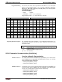
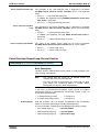
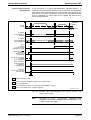
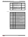
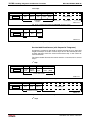
The
firmware
FWA-INDRV*-MPD-02VRS
for
configurable
BASIC UNIVERSAL double-axis control sections supports control
sections with the following type designations:
1)
2)
3)
4)
5)
6)
• CDB01.1C-xx -xxx -xxx -xxx -xxx -xx -S-NN-FW
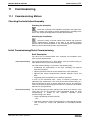
Possible types:
1)
… master communication, for both axes:
SE
→ SERCOS interface
PB → PPOFIBUS-DP
2)
… optional module 1 (X4.1), axis 1:
NNN → not equipped
EN1 → encoder interface for HSF/resolver
EN2 → encoder interface for EnDat/1Vpp sine/TTL signals
ENS → encoder interface for Rexroth standard/HIPERFACE/1Vpp
3)
… optional module 2 (X8.1), axis 1:
NNN → not equipped
EN1 → encoder interface for HSF/resolver
EN2 → encoder interface for EnDat/1Vpp sine/TTL signals
ENS → encoder interface for Rexroth standard/HIPERFACE/1Vpp
MA1 → analog I/Os
MEM → encoder emulator
4)
… optional module 1 (X4.2), axis 2:
NNN → not equipped
EN1 → encoder interface for HSF/resolver
EN2 → encoder interface for EnDat/1Vpp sine/TTL signals
ENS → encoder interface for Rexroth standard/HIPERFACE/1Vpp
5)
… optional module 2 (X8.2), axis 2:
NNN → not equipped
EN1 → encoder interface for HSF/resolver
EN2 → encoder interface for EnDat/1Vpp sine/TTL signals
ENS → encoder interface for Rexroth standard/HIPERFACE/1Vpp
MA1 → analog I/Os
MEM → encoder emulator
6)
… safety option, for both axes (X41.1 and X41.2):
NN → not equipped
L1
→ starting lockout
S1
→ module for safety technology
DOK-INDRV*-MP*-02VRS**-FK01-EN-P
System Overview 1-15
MPH-02, MPB-02, MPD-02
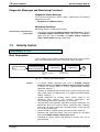
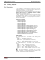
1.3
Motors and Measuring Systems
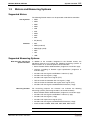
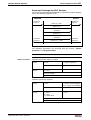
Supported Motors
The following Rexroth motors can be operated at IndraDrive controllers:
Housing Motors
• MHD
• MKD
• MKE
• MSK
• 2AD
• ADF
• MAD
• MAF
• MAL
• SF (Bosch)
Kit Motors
• MLF
• MBS (standard)
• MBS (high speed)
• MBT
• LSF
• 1MB
Supported Measuring Systems
Motor Encoders and External
Optional Encoders
In addition to the encoders integrated in the Rexroth motors, the
IndraDrive firmware can evaluate the following measuring systems as
motor encoders or as external optional control encoders:
• Bosch Rexroth GDS or GDM encoders (single-turn or multi-turn type)
• resolvers according to Rexroth signal specification (single-turn or
multi-turn type)
• encoders with sine signals and EnDat2.1 interface (1 Vpp)
• encoders with sine signals (1 Vpp)
• encoders with square-wave signals (TTL)
• Hall sensor box and encoder with sine signals (1 Vpp)
• Hall sensor box and encoder with square-wave signals (TTL)
• encoders with sine signals and HIPERFACE interface (1 Vpp)
Measuring Encoders
For measuring purposes the firmware can evaluate the following
measuring systems (measuring encoders, no control encoders):
• Bosch Rexroth GDS or GDM encoders (single-turn or multi-turn type)
• encoders with sine signals and EnDat2.1 interface (1 Vpp)
• encoders with sine signals (1 Vpp)
• encoders with square-wave signals (TTL)
• encoders with sine signals and HIPERFACE interface (1 Vpp)
• motor encoders of MSK, MHD, 2AD, ADF, MAD, MAF motors
Note:
DOK-INDRV*-MP*-02VRS**-FK01-EN-P
Resolvers cannot be evaluated as measuring encoders!
1-16 System Overview
1.4
MPH-02, MPB-02, MPD-02
Master Communication
In the firmware version FWA-INDRV*-MP*-02VRS (MPH, MPB and MPD
types) the following master communication interfaces are available:
• SERCOS interface
• PROFIBUS interface
• parallel interface (not for double-axis type MPD02)
• analog interface (not for double-axis type MPD02)
SERCOS interface
General Features
SERCOS interface
• cyclical data exchange of command values and actual values in equal
time intervals (max. 32 bytes per data direction; minimum cycle time of
500 µs)
• data transfer by means of fiber optic cable
• service channel for parameterization and diagnosis
• telegram contents can be freely configured (large number of
parameter IDNs configurable in the MDT and AT)
• synchronization between time command value takes effect and
measurement starting time of the actual values for all drives on a ring
PROFIBUS Interface
General Features
PROFIBUS Interface
• cyclical data exchange of command values and actual values
(max. 32 bytes per data direction; minimum cycle time of 250 µs)
• parameter channel for parameterization and diagnosis via the field bus
• telegram contents can be freely configured (large number of cyclically
configurable parameter IDNs)
Parallel Interface (not for MPD-02)
General Features
Parallel Interface
• complete control of the drive via digital inputs/outputs
• 16 inputs and 16 outputs
• serial interface for parameterization and diagnosis
• free configuration of digital inputs and outputs
Analog Interface (not for MPD-02)
General Features
Analog Interface
• basic unit has an analog input with 12-bit A/D converter and an input
voltage range of ± 10 V
• sampling is done with 8-fold oversampling in the position controller
clock
• assignment to command value/limit value/control parameters of the
drive possible by means of adjustable scaling
• parameterizable dead zone to suppress the zero drift
• low-pass filter to smooth the analog input signals
• zero adjust of the analog input signals by command
DOK-INDRV*-MP*-02VRS**-FK01-EN-P
System Overview 1-17
MPH-02, MPB-02, MPD-02
• "drive enable", "Drive Halt" and "clear error" preset via digital inputs
• diagnostic messages such as drive errors and warnings are output via
digital outputs
Note:
1.5
In addition to analog command value input, the actual position
value has to be transmitted back to the master, too. This
requires encoder emulation (see "Encoder Emulation" in
chapter "Extended Drive Functions").
Overview of Functions
Supported Operating Modes
The following operating modes are supported by the IndraDrive firmware
MPX-02:
• torque/force control
• velocity control
• position control with cyclic command value input
• drive-internal interpolation
• drive-controlled positioning
• positioning block mode
• synchronization modes:
• velocity synchronization with real/virtual master axis
• phase synchronization with real/virtual master axis
• electronic cam shaft with real/virtual master axis
Drive Functions
The following list contains the most important drive functions of the
IndraDrive firmware MP*-02VRS:
• Drive Halt
• friction torque compensation
• probe function
• E-Stop function
• spindle positioning
• undervoltage monitor
• output of control signals
• establishing the position data reference
• drive-controlled homing
• setting absolute measuring
• limitations that can be parameterized
• drive error reactions
• best possible deceleration
• package reaction on error
• NC reaction on error
• numerous diagnostic possibilities
DOK-INDRV*-MP*-02VRS**-FK01-EN-P
1-18 System Overview
MPH-02, MPB-02, MPD-02
• drive-internal generation of diagnostic messages
• analog output
• status displays, status classes
• oscilloscope function
• monitoring function
• patch function
• code of optional card
• parameter value check
• operating hours meter, logbook function, error memory
1.6
Functional Packages
Overview
The application-specific scope of usable functions
FWA-INDRV*-MPX-02VRS drive firmware depends on
of
the
• the available control section and, if available, its configuration
- and • the licensed functional firmware packages.
Note:
Depending on the hardware design, the scope of firmware
functionality can be determined according to the respective
application (scalability of the firmware functionality). The scope
of corresponding parameters depends on the available
functions.
Scaling the Drive Functionality
Firmware Scaling by Control
Section Configuration
The control sections of the IndraDrive controllers have a maximum of
4 optional card slots and a master communication slot. Depending on the
available optional cards, it is possible to activate certain functions (incl.
corresponding parameters):
• master communication (SERCOS interface, Profibus DP, parallel or
analog interface)
• safety technology (starting lockout, standard safety technology)
• analog I/O add-on card
• digital I/O add-on card
Note:
The functions and parameters for the evaluation of the
measuring systems as control encoders or measuring
encoders do not depend on the control section configuration
since their functions can be freely assigned to the various
optional encoder modules.
See also section "Drive Controllers"
DOK-INDRV*-MP*-02VRS**-FK01-EN-P
System Overview 1-19
MPH-02, MPB-02, MPD-02
Firmware Scaling by Functional
Packages
The firmware functionality is divided into the following package groups:
• base packages (open-loop or closed-loop)
• optional expansion packages:
• alternative functional packages
(expansion packages for servo function, main spindle function,
synchronization)
• additive functional package "IndraMotion MLD-S"
(drive-integrated PLC and technology functions)
Depending on the hardware configuration, the base packages are
available without any access enable. Using the optional expansion
packages, however, requires licensing.
Note:
The desired scope of firmware functions should preferably be
defined when the firmware is ordered. This guarantees that
the required functional packages have been enabled when the
firmware is delivered. In individual cases it is possible to
provide access enable subsequently (additional licensing) or to
reduce the activated scope of functions.
This procedure is described in section "Enabling of Functional
Packages" in chapter "Handling, Diagnostic and Service
Functions".
Note:
DOK-INDRV*-MP*-02VRS**-FK01-EN-P
The drive-integrated safety technology is a functionality
only scalable by means of the hardware and does not require
any additional enabling of functions!
1-20 System Overview
MPH-02, MPB-02, MPD-02
The figure below illustrates the possibilities of functional scaling
depending on the control performance:
BASIC
ADVANCED
single- and double-axis design
(firmware MPB02 and MPD02)
single-axis design
(firmware MPH02)
open-loop
closed-loop
open-loop
closed-loop
IndraMotion MLD-S
additive
functional
package
main spindle
synchronization
synchronization
synchronization
synchronization
servo
base package
open-loop
base package
closed-loop
servo
base package
open-loop
base package
closed-loop
base package
® always contained
functional packages ® optional expansion packages
Fig. 1-3:
alternative
functional
packages
DF000109v01_en.fh7
Functional packages of the IndraDrive firmware MPX02
Brief Description of the Functional Packages
The overall functionality of an IndraDrive device is divided into groups of
functions, the so-called "functional packages". The firmware FWAINDRV*-MPX-02VRS supports the functional packages listed below.
Note:
Base Packages
Each of the listed packages is available in basic or advanced
characteristic which differ with regard to their performance and
functionality.
The following base packages are available:
• "Open-loop" base package
motor control without encoder, no position control modes
→ no position evaluation and functions depending thereof
• "Closed-loop" base package
motor control with encoder (can be switched to control without
encoder)
→ position evaluation and functions and operating modes depending
thereof is possible
DOK-INDRV*-MP*-02VRS**-FK01-EN-P
System Overview 1-21
MPH-02, MPB-02, MPD-02
Alternative Functional Packages
The following alternative functional packages are available:
1)
• Servo functions :
This package contains all specific expansions for servo applications,
such as compensations and correction functions (e.g. axis error
correction, quadrant error correction).
1)
• Main spindle functions :
This package contains the specific functions for the use of main
spindles (e.g. spindle positioning).
1)
• Synchronization :
With this package the possibilities of synchronization of the drive can
be used (support of synchronization modes, measuring encoder
function, probe function ...).
1)
Note:
Additive Functional Packages
: These functional packages cannot be activated
simultaneously (only individually)! → Alternative expansion
packages
There is also an additional functional package available:
• IndraMotion MLD-S
Note:
This expansion package can be activated in addition to a
possibly available alternative package.
The overview below illustrates how the individual functional packages are
depending on the respective hardware and the firmware type:
Firmware type →
Control section design →
FWA-INDRV*-MPB-02VRS
FWA-INDRV*-MPD-02VRS
FWA-INDRV*-MPH-02VRS
CSB0.1.1
(Basic single-axis)
CDB0.1.1
(Basic double-axis)
CSH0.1.1
(Advanced single-axis)
without
encoder
performance
basic functions
base
package
base
package
"open-loop"
(U/f)
Basic
base
package
"closed-loop"
(Servo)
Basic
(open-loop)
with encoder
(closed-loop)
without
encoder
(open-loop)
with encoder
(closed-loop)
without
encoder
(open-loop)
with encoder
(closed-loop)
X
X
X
X
X
X
X
X
X
X
X
X
X
X
Advanced
X
X
X
Advanced
X
Basic
X
X
X
servo
Advanced
alternative
functional
packages
Basic
X
X
X
X
X
synchronizat.
Advanced
X
X
Basic
main spindle
Advanced
additive
functional
package
IndraMotion
MLD-S
X
Basic
Advanced
X
Fig. 1-4:
DOK-INDRV*-MP*-02VRS**-FK01-EN-P
X
Dependence of functional packages on hardware and firmware
variant
1-22 System Overview
MPH-02, MPB-02, MPD-02
Firmware Types That Can Be Ordered
IndraDrive firmware
Version
Release
Language
Open-/closedloop
Alternative
expansion
packages
Additive
expansion
packages
The type designation of the IndraDrive firmware consists of the following
type code elements:
Base package
(depending on
control section)
Structure of the
Firmware Type Designation
Basic single-axis
FWA-INDRV*
-MPB-
02
VRS-
D5-
x-
xxx-
xx
Basic double-axis
FWA-INDRV*
-MPD-
02
VRS-
D5-
x-
xxx-
xx
Advanced single-axis
FWA-INDRV*
-MPH-
02
VRS-
D5-
x-
xxx-
xx
Fig. 1-5:
Basic structure of the firmware type code
DOK-INDRV*-MP*-02VRS**-FK01-EN-P
System Overview 1-23
MPH-02, MPB-02, MPD-02
Advanced
single-axis
Open-/closedloop
Alternative
functional
packages
FWA-INDRV*-
MPB-
02
VRS-
D5-
0-
NNN
-NN base package (open-loop)
FWA-INDRV*-
MPB-
02
VRS-
D5-
0-
SNC
-NN base package (open-loop) + synchronization
FWA-INDRV*-
MPB-
02
VRS-
D5-
1-
NNN
-NN base package (closed-loop)
FWA-INDRV*-
MPB-
02
VRS-
D5-
1-
SRV
-NN base package (closed-loop) + servo function
FWA-INDRV*-
MPB-
02
VRS-
D5-
1-
SNC
-NN base package (closed-loop) + synchronization
FWA-INDRV*-
MPB-
02
VRS-
D5-
1-
ALL
-NN base package (closed-loop) + all altern. functions
FWA-INDRV*-
MPD-
02
VRS-
D5-
0-
NNN
-NN base package (open-loop)
FWA-INDRV*-
MPD-
02
VRS-
D5-
0-
SNC
-NN base package (open-loop) + synchronization
FWA-INDRV*-
MPD-
02
VRS-
D5-
1-
NNN
-NN base package (closed-loop)
FWA-INDRV*-
MPD-
02
VRS-
D5-
1-
SRV
-NN base package (closed-loop) + servo function
FWA-INDRV*-
MPD-
02
VRS-
D5-
1-
SNC
-NN base package (closed-loop) + synchronization
FWA-INDRV*-
MPD-
02
VRS-
D5-
1-
ALL
-NN base package (closed-loop) + all altern. functions
FWA-INDRV*-
MPH-
02
VRS-
D5-
0-
NNN
-NN base package (open-loop)
FWA-INDRV*-
MPH-
02
VRS-
D5-
0-
SNC
-NN base package (open-loop) + synchronization
FWA-INDRV*-
MPH-
02
VRS-
D5-
0-
ALL
-NN base package (open-loop) + all altern. functions
FWA-INDRV*-
MPH-
02
VRS-
D5-
0-
NNN
-ML base package (open-loop)
+ IndraMotion MLD-S
FWA-INDRV*-
MPH-
02
VRS-
D5-
0-
SNC
-ML base package (open-loop) + synchronization
+ IndraMotion MLD-S
FWA-INDRV*-
MPH-
02
VRS-
D5-
0-
ALL
-ML base package (open-loop) + all altern. functions
+ IndraMotion MLD-S
FWA-INDRV*-
MPH-
02
VRS-
D5-
1-
NNN
-NN base package (closed-loop)
FWA-INDRV*-
MPH-
02
VRS-
D5-
1-
SRV
-NN base package (closed-loop) + servo function
FWA-INDRV*-
MPH-
02
VRS-
D5-
1-
SNC
-NN base package (closed-loop) + synchronization
FWA-INDRV*-
MPH-
02
VRS-
D5-
1-
MSP
-NN base package (closed-loop) + main spindle
FWA-INDRV*-
MPH-
02
VRS-
D5-
1-
ALL
-NN base package (closed-loop) + all altern. functions
FWA-INDRV*-
MPH-
02
VRS-
D5-
1-
NNN
-ML base package (closed-loop)
+ IndraMotion MLD-S
FWA-INDRV*-
MPH-
02
VRS-
D5-
1-
SRV
-ML base package (closed-loop) + servo functions
+ IndraMotion MLD-S
FWA-INDRV*-
MPH-
02
VRS-
D5-
1-
SNC
-ML base package (closed-loop) + synchronization
+ IndraMotion MLD-S
FWA-INDRV*-
MPH-
02
VRS-
D5-
1-
MSP
-ML base package (closed-loop) + main spindle
+ IndraMotion MLD-S
FWA-INDRV*-
MPH-
02
VRS-
D5-
1-
ALL
-ML base package (closed-loop) + all altern. functions
+ IndraMotion MLD-S
Firmware
range
Fig. 1-6:
DOK-INDRV*-MP*-02VRS**-FK01-EN-P
Drive PLC
Language
Basic
double-axis
Release
Basic
single-axis
Version
Control
section
The individual functional packages can be combined to form the following
firmware types that can be ordered:
Base package
Firmware Types That Can Be
Ordered
Scope of functional packages
Overview of firmware types and functional packages they are
containing
1-24 System Overview
MPH-02, MPB-02, MPD-02
Base Packages
In the base packages of the firmware the minimum scope of
functionalities in the respective operating mode ("open-loop" or "closedloop") is available. They contain the basic functions of a drive firmware
and a number of other fundamental functions.
Basic Functions
The following basic functions are available for every drive and contain the
fundamental base functions of a digital drive (available as firmware
characteristics "open-loop" and "closed-loop"):
• numerous diagnostic possibilities
• drive-internal generation of diagnostic messages
• monitoring function
• analog output
• patch function
• status displays, status classes
• oscilloscope feature
• code of optional card
• parameter value check
• operating hours meter, logbook function, error memory
• undervoltage monitor
• output of control signals
• limits that can be parameterized
• serial communication
DOK-INDRV*-MP*-02VRS**-FK01-EN-P
System Overview 1-25
MPH-02, MPB-02, MPD-02
Scope of Functions of Base Packages
Apart from the basic functions there are other functions available in the
base package of the firmware. Their scope depends on the firmware
variant and its characteristic ("open-loop" or "closed-loop").
The following overview shows the available scope of functions of the
respective base package:
Firmware variant →
FWA-INDRV*-MPB02VRS
(Basic single-axis)
with encoder
(closed-loop)
without
encoder
(open-loop)
with encoder
(closed-loop)
without
encoder
(open-loop)
with encoder
(closed-loop)
X
X
X
X
X
X
SERCOS interface
X1)2)
X1)2)
X1)2)
X1)2)
X1)
X1)
PROFIBUS-DP
X1)2)
X1)2)
X1)2)
X1)2)
X1)
X1)
parallel interface
X1)3)
X1)3)
X1)
X1)
analog interface
X
X
signal control / signal status
word
Rexroth housing motors,
synchronous,
with encoder data memory
X
Rexroth housing motors,
asynchronous,
with encoder data memory
X
Rexroth kit motors,
synchronous,
without encoder data memory
Motors
and
encoders
Rexroth kit motors,
asynchronous,
without encoder data memory
motor holding brake
X
X
X
X
X
X
X
X
X
X
X
X
X
X
X
X
X
X
X
X
X
X
X4)
X
X4)
X
X4)
X
motor encoder
X
3)
optional control encoder
X
encoder correction
Axis
control
X
X
X
third-party motors, synchronous
third-party motors,
asynchronous
(standard motors)
Motor
control
FWA-INDRV*-MPH02VRS
(Advanced single-axis)
without
encoder
(open-loop)
Functions of the base
packages
Master
communication
FWA-INDRV*-MPD02VRS
(Basic double-axis)
X
X
X
X
X
X
X
overload protection
(temperature monitoring)
X
X
X
X
X
X
U/f operation
X
X
X
X
X
X
field-oriented current control,
with encoder
X
X
X
commutation setting
X
X
X
velocity loop
X
X
X
position loop
X
X
X
automatic axis control loop
setting
X
X
X
current limitation
X
X
X
X
X
X
torque/force limitation
X
X
X
X
X
X
Fig. 1-7:
DOK-INDRV*-MP*-02VRS**-FK01-EN-P
Scope of functions of the basic firmware packages (to be continued
on next page)
1-26 System Overview
MPH-02, MPB-02, MPD-02
Firmware type →
FWA-INDRV*-MPB02VRS
(Basic single-axis)
without
encoder
(open-loop)
Functions of the base
packages
torque/force control
Drive
functions
X
Expanded
drive
functions
without
encoder
(open-loop)
with encoder
(closed-loop)
X
X
X
X
X
X
X
X
X
drive-internal interpolation
X
X
X
drive-controlled positioning
X
X
X
positioning block mode
X
X
X
Drive Halt
X
X
X
X
X
X
travel range limit switch
X
X
X
X
X
X
position limit values
software limit switch)
X
detecting marker position
X
X
X
X
X
X
X
X
X
X
X
drive-controlled homing
X
X
X
setting absolute measuring
X
X
X
E-Stop function
X
X
X
X
X
X
torque disable
X
X
X
X
X
X
vcmd set to zero
("emergency halt")
X
X
X
X
X
X
vcmd set to zero with ramp and
filter ("quick stop")
X
X
X
X
X
X
analog I/Os (on basic device or
optional module)
X1)
X1)
X1)
X1)
X1)
X1)
digital I/Os (on basic device or
optional module)
X1)5)
X1)5)
X1)5)
X1)5)
X1)
X1)
encoder emulation
position switch points
3)
MMC support
Handling,
diagnosis,
service
X
with encoder
(closed-loop)
FWA-INDRV*-MPH02VRS
(Advanced single-axis)
position control
positive stop drive procedure
Error
reactions
without
encoder
(open-loop)
X
velocity control
Operating
modes
with encoder
(closed-loop)
FWA-INDRV*-MPD02VRS
(Basic double-axis)
X
X1)
X1)
X1)
X
X
X
3)
X
X
X
X
X
firmware handling
X
X
X
X
X
X
standard control panel
X
X
X
X
X
X
scaling/standardization
X
X
X
X
X
X
option. parameteriz. interface
X
X
X
X
X
X
oscilloscope feature
X
X
X
X
X
X
patch function
X
X
X
X
X
X
1)
depending on hardware configuration
2)
max. 24 byte MDT/AT data per axis and min. Tscyc = 1000 µs
3)
only with control section "BASIC UNIVERSAL"
4)
brake check and brake abrasion not possible
5)
no digital I/Os on optional module for basic design
Fig. 1-8:
Scope of functions of the basic firmware packages (continuation)
DOK-INDRV*-MP*-02VRS**-FK01-EN-P
System Overview 1-27
MPH-02, MPB-02, MPD-02
Alternative Functional Packages
Apart from the base packages that are always available, we offer optional
expansion packages. Part of the expansion packages is the group of
alternative functional packages; from this group only one package can be
activated at a time (alternative activation).
At present, there are the following alternative expansion packages
available:
•
expanded servo function
•
synchronization
•
main spindle function
Servo Function
Depending on the firmware variant and characteristic, the expansion
package "servo" (only possible with "closed-loop") has the following scope
of functions:
Firmware type →
Functions of the expansion
package "servo"
FWA-INDRV*-MPB-02VRS
(Basic single-axis)
without
encoder
(open-loop)
with encoder
(closed-loop)
FWA-INDRV*-MPD-02VRS
(Basic double-axis)
without
encoder
(open-loop)
with encoder
(closed-loop)
FWA-INDRV*-MPH-02VRS
(Advanced single-axis)
without
encoder
(open-loop)
quadrant error correction
with encoder
(closed-loop)
X
friction torque compensation
X
X
X
set/shift coordinate system
X
X
X
1)
axis error correction
X
2)
probe function
X
relative return motion
DOK-INDRV*-MP*-02VRS**-FK01-EN-P
X
1)
X
2)
X2)
X
X
X
X
1)
only single reversal clearance; no correction tables
2)
for Advanced single-axis 2 probes; for Basic single-axis only
1 probe; for Basic double-axis 2 probes per controller
Fig. 1-9:
Overview expansion package "servo"
Note:
For hardware design "BASIC …" the probe input is only
available
for
control
sections
"BASIC SERCOS",
"BASIC PROFIBUS" and "BASIC UNIVERSAL" (CSB01.1***).
1-28 System Overview
MPH-02, MPB-02, MPD-02
Synchronization
Depending on the firmware variant and characteristic, the expansion
package "synchronization" has the following scope of functions:
Firmware type →
Functions of the expansion
package "synchronization"
FWA-INDRV*-MPB-02VRS
(Basic single-axis)
without
encoder
(open-loop)
measuring wheel mode
with encoder
(closed-loop)
FWA-INDRV*-MPD-02VRS
(Basic double-axis)
without
encoder
(open-loop)
X
velocity synchronization
X
FWA-INDRV*-MPH-02VRS
(Advanced single-axis)
without
encoder
with encoder
(closed-loop)
(open-loop)
X
X
X
with encoder
(closed-loop)
X
X
X
X
phase synchronization
X
X
X
electronic cam shaft
X
X
X
set/shift coordinate system
X
2)3)
probe function
X
X4)
measuring encoder
2)
X
X
2)3)
X
X4)
X
X
2)
3)
X
X
X2)
X
X
X
2)
for Advanced single-axis 2 probes; for Basic single-axis only
1 probe; for Basic double-axis 2 probes per controller
3)
in parameter S-0-0428, Probe, IDN list signal selection the
following signals are not available S-0-0051, S-0-0052, P-0-0227
4)
only with control section "BASIC UNIVERSAL"
Fig. 1-10:
Overview expansion package "synchronization"
Note:
For hardware design "BASIC …" the probe input is only
available
for
control
sections
"BASIC SERCOS",
"BASIC PROFIBUS" and "BASIC UNIVERSAL" (CSB01.1***).
Main Spindle Function
The expansion package "main spindle" (only possible with "closed-loop")
has the following scope of functions:
Firmware type →
Functions of the expansion
package "main spindle"
FWA-INDRV*-MPB-02VRS
(Basic single-axis)
FWA-INDRV*-MPD-02VRS
(Basic double-axis)
without
encoder
(open-loop)
without
encoder
(open-loop)
with encoder
(closed-loop)
FWA-INDRV*-MPH-02VRS
(Advanced single-axis)
without
encoder
with encoder
(closed-loop)
(open-loop)
with encoder
(closed-loop)
spindle positioning
X
set/shift coordinate system
X
Fig. 1-11:
Overview expansion package "main spindle"
•
Additive Functional Packages
The so-called additive functional packages are part of the optional
expansion packages. Additive functional packages can be used in
addition to the base function and one of the alternative functional
packages (additive activation).
At present, there is the following additive functional package available:
• IndraMotion MLD-S
(drive-integrated PLC and technology functions)
DOK-INDRV*-MP*-02VRS**-FK01-EN-P
System Overview 1-29
MPH-02, MPB-02, MPD-02
Note:
The drive-integrated safety technology is a functionality
only scalable by means of the hardware and is not part of the
expansion packages that can be enabled!
IndraMotion MLD-S (Drive-Integrated PLC)
The expansion package "IndraMotion MLD-S" makes available the
following scope of functions:
• integrated logic control (standard PLC tasks)
• integrated single-axis motion control
motion function block according to PLC-Open for single-axis
positioning and synchronization mode (synchronous running, cam
shaft)
→ "low-level motion functions"
• basis for technology functions
examples: following-on cutting devices, pick & place, process
controller (register controller, winding computation, etc.), preventive
maintenance, free function block combination
Note:
The expansion package "IndraMotion MLD-S" is only available
in conjunction with ADVANCED control sections (CSH-***)!
Drive-Integrated Safety Technology
Note:
The drive-integrated safety technology is a functionality
only scalable by means of the hardware and does not require
any additional enabling of functions! The requirement for using
this function is the use of the optional safety module S1
depending on the control section configuration.
The following safety functions are supported:
• safety related stopping process:
• safety related standstill
• safety related operational stop
• safety related starting lockout
• safety related motion:
• safety related reduced speed
• safety related direction of motion
• safety related limited increment
• safety related limited absolute position
• safety related acceleration/deceleration
• safety related feedback:
• safety related diagnosis outputs
• safety related safety door
• Safety related maximum velocity
• Safety related end position (in preparation)
DOK-INDRV*-MP*-02VRS**-FK01-EN-P
1-30 System Overview
MPH-02, MPB-02, MPD-02
Notes
DOK-INDRV*-MP*-02VRS**-FK01-EN-P
Important directions for use 2-1
MPH-02, MPB-02, MPD-02
2
Important directions for use
2.1
Appropriate use
Introduction
Rexroth products represent state-of-the-art developments and
manufacturing. They are tested prior to delivery to ensure operating safety
and reliability.
The products may only be used in the manner that is defined as
appropriate. If they are used in an inappropriate manner, then situations
can develop that may lead to property damage or injury to personnel.
Note:
Bosch Rexroth, as manufacturer, is not liable for any damages
resulting from inappropriate use. In such cases, the guarantee
and the right to payment of damages resulting from
inappropriate use are forfeited. The user alone carries all
responsibility of the risks.
Before using Rexroth products, make sure that all the pre-requisites for
an appropriate use of the products are satisfied:
• Personnel that in any way, shape or form uses our products must first
read and understand the relevant safety instructions and be familiar
with appropriate use.
• If the product takes the form of hardware, then they must remain in
their original state, in other words, no structural changes are permitted.
It is not permitted to decompile software products or alter source
codes.
DOK-INDRV*-MP*-02VRS**-FK01-EN-P
•
Do not mount damaged or faulty products or use them in operation.
•
Make sure that the products have been installed in the manner
described in the relevant documentation.
2-2 Important directions for use
MPH-02, MPB-02, MPD-02
Areas of use and application
Drive controllers made by Bosch Rexroth are designed to control
electrical motors and monitor their operation.
Control and monitoring of the motors may require additional sensors and
actors.
Note:
The drive controllers may only be used with the accessories
and parts specified in this document. If a component has not
been specifically named, then it may not be either mounted or
connected. The same applies to cables and lines.
Operation is only permitted in the specified configurations and
combinations of components using the software and firmware
as specified in the relevant function descriptions.
Every drive controller has to be programmed before starting it up, making
it possible for the motor to execute the specific functions of an application.
The drive controllers of the IndraDrive family are designed for use in
single or multiple-axis drive and control applications.
To ensure an application-specific use, the drive controllers are available
with differing drive power and different interfaces.
Typical applications of drive controllers belonging to the IndraDrive family
are:
•
handling and mounting systems,
•
packaging and foodstuff machines,
•
printing and paper processing machines and
•
machine tools.
The drive controllers may only be operated under the assembly,
installation and ambient conditions as described here (temperature,
system of protection, humidity, EMC requirements, etc.) and in the
position specified.
2.2
Inappropriate use
Using the drive controllers outside of the above-referenced areas of
application or under operating conditions other than described in the
document and the technical data specified is defined as “inappropriate
use".
Drive controllers may not be used if
•
they are subject to operating conditions that do not meet the above
specified ambient conditions. This includes, for example, operation
under water, in the case of extreme temperature fluctuations or
extremely high maximum temperatures or if
•
Rexroth has not specifically released them for that intended purpose.
Please note the specifications outlined in the general safety
instructions!
DOK-INDRV*-MP*-02VRS**-FK01-EN-P
Safety Instructions for Electric Drives and Controls 3-1
MPH-02, MPB-02, MPD-02
3
Safety Instructions for Electric Drives and Controls
3.1
Introduction
Read these instructions before the initial startup of the equipment in order
to eliminate the risk of bodily harm or material damage. Follow these
safety instructions at all times.
Do not attempt to install or start up this equipment without first reading all
documentation provided with the product. Read and understand these
safety instructions and all user documentation of the equipment prior to
working with the equipment at any time. If you do not have the user
documentation for your equipment, contact your local Bosch Rexroth
representative to send this documentation immediately to the person or
persons responsible for the safe operation of this equipment.
If the equipment is resold, rented or transferred or passed on to others,
then these safety instructions must be delivered with the equipment.
WARNING
3.2
Improper use of this equipment, failure to follow
the safety instructions in this document or
tampering with the product, including disabling
of safety devices, may result in material
damage, bodily harm, electric shock or even
death!
Explanations
The safety instructions describe the following degrees of hazard
seriousness in compliance with ANSI Z535. The degree of hazard
seriousness informs about the consequences resulting from noncompliance with the safety instructions.
Warning symbol with signal
word
Degree of hazard seriousness according
to ANSI
Death or severe bodily harm will occur.
DANGER
Death or severe bodily harm may occur.
WARNING
Bodily harm or material damage may occur.
CAUTION
Fig. 3-1:
DOK-INDRV*-MP*-02VRS**-FK01-EN-P
Hazard classification (according to ANSI Z535)
3-2 Safety Instructions for Electric Drives and Controls
3.3
MPH-02, MPB-02, MPD-02
Hazards by Improper Use
High voltage and high discharge current!
Danger to life or severe bodily harm by electric
shock!
DANGER
Dangerous movements! Danger to life, severe
bodily harm or material damage by
unintentional motor movements!
DANGER
High electrical voltage due to wrong
connections! Danger to life or bodily harm by
electric shock!
WARNING
Health hazard for persons with heart
pacemakers, metal implants and hearing aids in
proximity to electrical equipment!
WARNING
Surface of machine housing could be extremely
hot! Danger of injury! Danger of burns!
CAUTION
CAUTION
Risk of injury due to improper handling! Bodily
harm caused by crushing, shearing, cutting and
mechanical shock or incorrect handling of
pressurized systems!
Risk of injury due to incorrect handling of
batteries!
CAUTION
DOK-INDRV*-MP*-02VRS**-FK01-EN-P
Safety Instructions for Electric Drives and Controls 3-3
MPH-02, MPB-02, MPD-02
3.4
General Information
• Bosch Rexroth AG is not liable for damages resulting from failure to
observe the warnings provided in this documentation.
• Read the operating, maintenance and safety instructions in your
language before starting up the machine. If you find that you cannot
completely understand the documentation for your product, please ask
your supplier to clarify.
• Proper and correct transport, storage, assembly and installation as
well as care in operation and maintenance are prerequisites for
optimal and safe operation of this equipment.
• Only persons who are trained and qualified for the use and operation
of the equipment may work on this equipment or within its proximity.
• The persons are qualified if they have sufficient knowledge of the
assembly, installation and operation of the equipment as well as an
understanding of all warnings and precautionary measures noted in
these instructions.
• Furthermore, they must be trained, instructed and qualified to
switch electrical circuits and equipment on and off in accordance
with technical safety regulations, to ground them and to mark them
according to the requirements of safe work practices. They must
have adequate safety equipment and be trained in first aid.
• Only use spare parts and accessories approved by the manufacturer.
• Follow all safety regulations and requirements for the specific
application as practiced in the country of use.
• The equipment is designed for installation in industrial machinery.
• The ambient conditions given in the product documentation must be
observed.
• Use only safety features and applications that are clearly and explicitly
approved in the Project Planning Manual.
For example, the following areas of use are not permitted: construction
cranes, elevators used for people or freight, devices and vehicles to
transport people, medical applications, refinery plants, transport of
hazardous goods, nuclear applications, applications sensitive to high
frequency, mining, food processing, control of protection equipment
(also in a machine).
• The information given in the documentation of the product with regard
to the use of the delivered components contains only examples of
applications and suggestions.
The machine and installation manufacturer must
• make sure that the delivered components are suited for his
individual application and check the information given in this
documentation with regard to the use of the components,
• make sure that his application complies with the applicable safety
regulations and standards and carry out the required measures,
modifications and complements.
• Startup of the delivered components is only permitted once it is sure
that the machine or installation in which they are installed complies
with the national regulations, safety specifications and standards of the
application.
DOK-INDRV*-MP*-02VRS**-FK01-EN-P
3-4 Safety Instructions for Electric Drives and Controls
MPH-02, MPB-02, MPD-02
• Operation is only permitted if the national EMC regulations for the
application are met.
The instructions for installation in accordance with EMC requirements
can be found in the documentation "EMC in Drive and Control
Systems".
The machine or installation manufacturer is responsible for
compliance with the limiting values as prescribed in the national
regulations.
• Technical data, connections and operational conditions are specified in
the product documentation and must be followed at all times.
DOK-INDRV*-MP*-02VRS**-FK01-EN-P
Safety Instructions for Electric Drives and Controls 3-5
MPH-02, MPB-02, MPD-02
3.5
Protection Against Contact with Electrical Parts
Note:
This section refers to equipment and drive components with
voltages above 50 Volts.
Touching live parts with voltages of 50 Volts and more with bare hands or
conductive tools or touching ungrounded housings can be dangerous and
cause electric shock. In order to operate electrical equipment, certain
parts must unavoidably have dangerous voltages applied to them.
High electrical voltage! Danger to life, severe
bodily harm by electric shock!
DANGER
DOK-INDRV*-MP*-02VRS**-FK01-EN-P
⇒ Only those trained and qualified to work with or on
electrical equipment are permitted to operate, maintain
or repair this equipment.
⇒ Follow general construction and safety regulations when
working on high voltage installations.
⇒ Before switching on power the ground wire must be
permanently connected to all electrical units according
to the connection diagram.
⇒ Do not operate electrical equipment at any time, even
for brief measurements or tests, if the ground wire is not
permanently connected to the points of the components
provided for this purpose.
⇒ Before working with electrical parts with voltage higher
than 50 V, the equipment must be disconnected from
the mains voltage or power supply. Make sure the
equipment cannot be switched on again unintended.
⇒ The following should be observed with electrical drive
and filter components:
⇒ Wait five (5) minutes after switching off power to allow
capacitors to discharge before beginning to work.
Measure the voltage on the capacitors before beginning
to work to make sure that the equipment is safe to
touch.
⇒ Never touch the electrical connection points of a
component while power is turned on.
⇒ Install the covers and guards provided with the
equipment properly before switching the equipment on.
Prevent contact with live parts at any time.
⇒ A residual-current-operated protective device (RCD)
must not be used on electric drives! Indirect contact
must be prevented by other means, for example, by an
overcurrent protective device.
⇒ Electrical components with exposed live parts and
uncovered high voltage terminals must be installed in a
protective housing, for example, in a control cabinet.
3-6 Safety Instructions for Electric Drives and Controls
MPH-02, MPB-02, MPD-02
To be observed with electrical drive and filter components:
High electrical voltage on the housing!
High leakage current! Danger to life, danger of
injury by electric shock!
DANGER
3.6
⇒ Connect the electrical equipment, the housings of all
electrical units and motors permanently with the safety
conductor at the ground points before power is
switched on. Look at the connection diagram. This is
even necessary for brief tests.
⇒ Connect the safety conductor of the electrical
equipment always permanently and firmly to the
supply mains. Leakage current exceeds 3.5 mA in
normal operation.
⇒ Use a copper conductor with at least 10 mm² cross
section over its entire course for this safety conductor
connection!
⇒ Prior to startups, even for brief tests, always connect
the protective conductor or connect with ground wire.
Otherwise, high voltages can occur on the housing
that lead to electric shock.
Protection Against Electric Shock by Protective Low
Voltage (PELV)
All connections and terminals with voltages between 0 and 50 Volts on
Rexroth products are protective low voltages designed in accordance with
international standards on electrical safety.
High electrical voltage due to wrong
connections! Danger to life, bodily harm by
electric shock!
WARNING
⇒ Only connect equipment, electrical components and
cables of the protective low voltage type (PELV =
Protective Extra Low Voltage) to all terminals and
clamps with voltages of 0 to 50 Volts.
⇒ Only electrical circuits may be connected which are
safely isolated against high voltage circuits. Safe
isolation is achieved, for example, with an isolating
transformer, an opto-electronic coupler or when
battery-operated.
DOK-INDRV*-MP*-02VRS**-FK01-EN-P
MPH-02, MPB-02, MPD-02
3.7
Safety Instructions for Electric Drives and Controls 3-7
Protection Against Dangerous Movements
Dangerous movements can be caused by faulty control of the connected
motors. Some common examples are:
• improper or wrong wiring of cable connections
• incorrect operation of the equipment components
• wrong input of parameters before operation
• malfunction of sensors, encoders and monitoring devices
• defective components
• software or firmware errors
Dangerous movements can occur immediately after equipment is
switched on or even after an unspecified time of trouble-free operation.
The monitoring in the drive components will normally be sufficient to avoid
faulty operation in the connected drives. Regarding personal safety,
especially the danger of bodily injury and material damage, this alone
cannot be relied upon to ensure complete safety. Until the integrated
monitoring functions become effective, it must be assumed in any case
that faulty drive movements will occur. The extent of faulty drive
movements depends upon the type of control and the state of operation.
DOK-INDRV*-MP*-02VRS**-FK01-EN-P
3-8 Safety Instructions for Electric Drives and Controls
MPH-02, MPB-02, MPD-02
Dangerous movements! Danger to life, risk of
injury, severe bodily harm or material damage!
DANGER
⇒ Ensure personal safety by means of qualified and
tested higher-level monitoring devices or measures
integrated in the installation. Unintended machine
motion is possible if monitoring devices are disabled,
bypassed or not activated.
⇒ Pay attention to unintended machine motion or other
malfunction in any mode of operation.
⇒ Keep free and clear of the machine’s range of motion
and moving parts. Possible measures to prevent
people from accidentally entering the machine’s range
of motion:
- use safety fences
- use safety guards
- use protective coverings
- install light curtains or light barriers
⇒ Fences and coverings must be strong enough to
resist maximum possible momentum, especially if
there is a possibility of loose parts flying off.
⇒ Mount the emergency stop switch in the immediate
reach of the operator. Verify that the emergency stop
works before startup. Don’t operate the machine if the
emergency stop is not working.
⇒ Isolate the drive power connection by means of an
emergency stop circuit or use a starting lockout to
prevent unintentional start.
⇒ Make sure that the drives are brought to a safe
standstill before accessing or entering the danger
zone. Safe standstill can be achieved by switching off
the power supply contactor or by safe mechanical
locking of moving parts.
⇒ Secure vertical axes against falling or dropping after
switching off the motor power by, for example:
- mechanically securing the vertical axes
- adding an external braking/ arrester/ clamping
mechanism
- ensuring sufficient equilibration of the vertical axes
The standard equipment motor brake or an external
brake controlled directly by the drive controller are
not sufficient to guarantee personal safety!
DOK-INDRV*-MP*-02VRS**-FK01-EN-P
Safety Instructions for Electric Drives and Controls 3-9
MPH-02, MPB-02, MPD-02
⇒ Disconnect electrical power to the equipment using a
master switch and secure the switch against
reconnection for:
- maintenance and repair work
- cleaning of equipment
- long periods of discontinued equipment use
⇒ Prevent the operation of high-frequency, remote
control and radio equipment near electronics circuits
and supply leads. If the use of such equipment cannot
be avoided, verify the system and the installation for
possible malfunctions in all possible positions of
normal use before initial startup. If necessary, perform
a special electromagnetic compatibility (EMC) test on
the installation.
3.8
Protection Against Magnetic and Electromagnetic Fields
During Operation and Mounting
Magnetic and electromagnetic fields generated near current-carrying
conductors and permanent magnets in motors represent a serious health
hazard to persons with heart pacemakers, metal implants and hearing
aids.
Health hazard for persons with heart
pacemakers, metal implants and hearing aids in
proximity to electrical equipment!
WARNING
⇒ Persons with heart pacemakers, hearing aids and
metal implants are not permitted to enter the following
areas:
- Areas in which electrical equipment and parts are
mounted, being operated or started up.
- Areas in which parts of motors with permanent
magnets are being stored, operated, repaired or
mounted.
⇒ If it is necessary for a person with a heart pacemaker
to enter such an area, then a doctor must be
consulted prior to doing so. Heart pacemakers that
are already implanted or will be implanted in the
future, have a considerable variation in their electrical
noise immunity. Therefore there are no rules with
general validity.
⇒ Persons with hearing aids, metal implants or metal
pieces must consult a doctor before they enter the
areas described above. Otherwise, health hazards will
occur.
DOK-INDRV*-MP*-02VRS**-FK01-EN-P
3-10 Safety Instructions for Electric Drives and Controls
3.9
MPH-02, MPB-02, MPD-02
Protection Against Contact with Hot Parts
Housing surfaces could be extremely hot!
Danger of injury! Danger of burns!
CAUTION
⇒ Do not touch housing surfaces near sources of heat!
Danger of burns!
⇒ After switching the equipment off, wait at least ten (10)
minutes to allow it to cool down before touching it.
⇒ Do not touch hot parts of the equipment, such as
housings with integrated heat sinks and resistors.
Danger of burns!
3.10 Protection During Handling and Mounting
Under certain conditions, incorrect handling and mounting of parts and
components may cause injuries.
Risk of injury by incorrect handling! Bodily
harm caused by crushing, shearing, cutting and
mechanical shock!
CAUTION
⇒ Observe general installation and safety instructions
with regard to handling and mounting.
⇒ Use appropriate mounting and transport equipment.
⇒ Take precautions to avoid pinching and crushing.
⇒ Use only appropriate tools. If specified by the product
documentation, special tools must be used.
⇒ Use lifting devices and tools correctly and safely.
⇒ For safe protection wear appropriate protective
clothing, e.g. safety glasses, safety shoes and safety
gloves.
⇒ Never stand under suspended loads.
⇒ Clean up liquids from the floor immediately to prevent
slipping.
DOK-INDRV*-MP*-02VRS**-FK01-EN-P
Safety Instructions for Electric Drives and Controls 3-11
MPH-02, MPB-02, MPD-02
3.11 Battery Safety
Batteries contain reactive chemicals in a solid housing. Inappropriate
handling may result in injuries or material damage.
Risk of injury by incorrect handling!
CAUTION
Note:
⇒ Do not attempt to reactivate discharged batteries by
heating or other methods (danger of explosion and
cauterization).
⇒ Never charge non-chargeable batteries (danger of
leakage and explosion).
⇒ Never throw batteries into a fire.
⇒ Do not dismantle batteries.
⇒ Do not damage electrical components installed in the
equipment.
Be aware of environmental protection and disposal! The
batteries contained in the product should be considered as
hazardous material for land, air and sea transport in the sense
of the legal requirements (danger of explosion). Dispose
batteries separately from other waste. Observe the legal
requirements in the country of installation.
3.12 Protection Against Pressurized Systems
Certain motors and drive controllers, corresponding to the information in
the respective Project Planning Manual, must be provided with
pressurized media, such as compressed air, hydraulic oil, cooling fluid
and cooling lubricant supplied by external systems. Incorrect handling of
the supply and connections of pressurized systems can lead to injuries or
accidents. In these cases, improper handling of external supply systems,
supply lines or connections can cause injuries or material damage.
Danger of injury by incorrect handling of
pressurized systems !
CAUTION
Note:
DOK-INDRV*-MP*-02VRS**-FK01-EN-P
⇒ Do not attempt to disassemble, to open or to cut a
pressurized system (danger of explosion).
⇒ Observe the operation instructions of the respective
manufacturer.
⇒ Before disassembling pressurized systems, release
pressure and drain off the fluid or gas.
⇒ Use suitable protective clothing (for example safety
glasses, safety shoes and safety gloves)
⇒ Remove any fluid that has leaked out onto the floor
immediately.
Environmental protection and disposal! The media used in the
operation of the pressurized system equipment may not be
environmentally compatible. Media that are damaging the
environment must be disposed separately from normal waste.
Observe the legal requirements in the country of installation.
3-12 Safety Instructions for Electric Drives and Controls
MPH-02, MPB-02, MPD-02
Notes
DOK-INDRV*-MP*-02VRS**-FK01-EN-P
Master Communication 4-1
MPH-02, MPB-02, MPD-02
4
Master Communication
4.1
Basic Functions of Master Communication
The basic functions of master communication apply to each type of
master communication, in the case of IndraDrive devices to
SERCOS interface, field bus interface, parallel and analog interface.
The following are the basic functions:
• address assignment
• command processing
• device control (status machine)
Possibility of control for all IndraDrive master communications via:
• signal control word/signal status word
Address Assignment
Each drive is identified by its own address. Multiple addressing is not
allowed.
Condition As Supplied
In the condition as supplied the address "99" is set.
Note:
The address entered in parameter P-0-4025, Drive address
of master communication takes effect during the transition
from P0 → P1. The active device address is displayed in
parameter S-0-0096, Slave arrangement (SLKN).
Address Setting via Control Panel
The drive address for IndraDrive controllers can be set via the standard
control panel at the front of the device.
8-digit display
1
F4002
Esc
Enter
"Down"
"Up"
buttons
DG0001v1.fh7
Fig. 4-1:
DOK-INDRV*-MP*-02VRS**-FK01-EN-P
Standard control panel (example of display)
4-2 Master Communication
MPH-02, MPB-02, MPD-02
The address is set via the control panel as follows:
1. change to "commands/settings" mode
2.Comand
commands/settings
"Up" button
standard display
e.g.:
Fig. 4-2:
1
F2002
press "Enter"
and "Esc"
buttons for
8 seconds
extended display
1.Er.Anz
Activating the "commands/settings" mode
2. select element "2.1 drive address" by means of "Up/Down" buttons,
then confirm by means of "Enter" button
3. set drive address by means of "Up/Down" buttons, then confirm by
means of "Enter" button
• first set tens digit:
→ the display reads "2.1.1 drive address"
• then set units digit:
→ the display reads "2.1.2 drive address"
Note:
The tens or units digit is accepted by pressing the "Enter"
button. To return press the "Esc" button.
drive address
2.Comand
"Enter" button
"Enter" button
"Enter" button
2.1 Adr.
"Esc" button
"Esc" button
2.1.1 ZE
"Esc" button
set tens digit with "Up/Down"
buttons
2.1.2 ZE
set units digit with "Up/Down"
buttons
accept with "Enter" button
commands/settings
"Up" button
display
display
display
"Down" button
explanation: Y.Y
XXXXXXXX
display changes (flashes)
between "Y.Y" and "XXXXXXXX"
1.Er.Anz
ZE … tens/units ("Zehner/Einer") digit of drive
address
extended display
Fig. 4-3:
Selecting and setting the drive address
Address Setting via Parameter
The drive address can also be set by writing the P-0-4025, Drive address
of master communication parameter. This is particularly interesting if
you administrate the axis data in centralized form in the control unit and
want to set the address from the control unit when replacing devices.
See also "Notes on How to Replace the Devices" in chapter "Handling,
Diagnostic and Service Functions"
DOK-INDRV*-MP*-02VRS**-FK01-EN-P
Master Communication 4-3
MPH-02, MPB-02, MPD-02
Command Processing
Basics
Commands are used to control complex functions in the drive. For
example, the functions "Drive-controlled homing procedure" or "Transition
check for communication phase 4" are defined as commands.
The higher-level master can start, interrupt or clear commands. Belonging
to each command there is a parameter with which the command can be
controlled.
While a command is being executed, the diagnostic message "Cx"
appears on the display, "x" representing the number of the command.
Note:
List of All Commands
Kinds of Commands
Each command that was started by a control unit must be
actively cleared again.
All commands available in the drive are stored in the S-0-0025, IDN-list
of all procedure commands parameter.
There are 3 different kinds of commands:
• Drive control commands
• can cause automatic drive motion,
• can be started only when drive enable has been set,
• deactivate the active operating mode during its execution.
• Monitoring commands
• activate or deactivate monitors or functions in the drive.
• Administration commands
• carry out administration tasks,
• cannot be interrupted.
Command Input and Acknowledgment
The command execution is controlled and monitored by command input
and command acknowledgment. In the input the drive is informed on
whether the command is to be started, interrupted or completed. The
input takes place via the operating data of the respective parameter.
Command Input
Command Acknowledgment
The command input can be:
• 0:
not set and not enabled
• 1:
interrupted
• 3:
set and enabled
In the command acknowledgment, the drive informs about the current
status of the command execution. The current status is contained in the
data status of the command parameter.
Note:
Command Status
The command status can be obtained by executing a
command to write data to the parameter element 1 (data
status) of the command parameter.
The command status can be:
• 0x0: not set and not enabled
• 0x7: in process
DOK-INDRV*-MP*-02VRS**-FK01-EN-P
4-4 Master Communication
MPH-02, MPB-02, MPD-02
• 0xF: error, command execution impossible
• 0x5: command execution interrupted
• 0x3: command correctly executed
Command Change Bit
For master-side detection of a change of the command acknowledgment
by the drive the "command change bit" (KA bit) is available in S-0-0135,
Drive status word.
• The bit is set by the drive when the command acknowledgment
changes from the "in process" (0x7) status to the "error, command
execution impossible" (0xF) or "command correctly executed" (0x3)
status.
• The bit is cleared when the master clears the input (0x0).
data of
command
parameter
(= input) 3
command
started
command
cleared
0
t
data status of
command 7
parameter
(= acknow- 3
ledgment) 0
command
processed
command completed
without error
command cleared
t
approx. 2 ms
approx. 2 ms
command
change bit
in drive status 1
word
0
t
DK000024v01_en.fh7
Fig. 4-4:
Input, acknowledgment and command change bit in the case of
correct execution
data of
command
parameter
(= input) 3
command
started
command
cleared
0
t
0xF
data status of
command
parameter 7
(= acknowledgment) 3
command
processed
command completed
with error
command cleared
0
t
approx. 2 ms
approx. 2 ms
command
change bit
in drive status 1
word
0
t
DK000025v01_en.fh7
Fig. 4-5:
Input, acknowledgment and command change bit in the case of
incorrect execution
DOK-INDRV*-MP*-02VRS**-FK01-EN-P
Master Communication 4-5
MPH-02, MPB-02, MPD-02
Device Control (Status Machine)
Brief Description
The drive status (e.g. Drive Halt, drive errors) represents a specific
internal and external drive behavior. The drive status can be exited by
defined events (e.g. drive commands, switching of operating modes).
Corresponding status transitions are assigned to the events. The status
transitions or the interaction of control and status bits are called status
machine. The figure below shows the schematic diagram of the device
control (status machine) of an IndraDrive device.
DOK-INDRV*-MP*-02VRS**-FK01-EN-P
4-6 Master Communication
MPH-02, MPB-02, MPD-02
P-0-0116, Device control: control word
Bit 15
® drive ON
Bit 14
® drive enable
Bit 13
® Drive Halt
P-0-0115, Device control: status word
Bit 15...14 ® readiness for operation
Bit 13
® drive error
Bit 4
® Drive Halt
Bit 3
® drive follows command value
S-0-0014, Interface status
Bit 2...0
® active communication phase
Drive Halt (AH)
P-0-0115: Bit 15...13 = 110
Bit 4,3 = 10
S-0-0014: Bit 2...0 = 100
command execution
P-0-0115: Bit 15...13 = 110
Bit 4,3 = 00
S-0-0014: Bit 2...0 = 100
e.g. spindle positioning
homing
set absol. measuring
start
command
P-0-0116:
Bit 15...13 = 110
P-0-0116:
Bit 15...13 = 111
WARNING
P-0-0115: Bit 2 = 1
error situation
(e.g. F8060)
complete
command
drive enable (AF)
Fxxx
P-0-0115: Bit 15...13 = 110
Bit 4,3 = 01
S-0-0014: Bit 2...0 = 100
P-0-0115: Bit 15...13 = 101
Bit 4,3 = 00
S-0-0014: Bit 2...0 = 100
sec. oper. mode 3
sec. oper. mode 2
sec. oper. mode 1
prim. mode of oper.
(depending on error class
and parameterization)
error reaction
drive in control
P-0-0116:
Bit 15...13 = 011
C0400 (P-0-4023)
(not for SERCOS)
C0401
P-0-0116:
Bit 15...13 = x0x
P-0-0116:
Bit 15...13 = 01x
torque
disable
(only for SERCOS)
best possible
deceleration
(cf. P-0-0119)
C0500
(S-0-0099)
drive ready (Ab)
P-0-0115: Bit 15...13 = 11x
Bit 4,3 = 0x
S-0-0014: Bit 2...0 = 100
P-0-0115: Bit 15...13 = 100
Bit 4,3 = 00
S-0-0014: Bit 2...0 = 100
power
OFF
power
ON
ready for oper. (bb)
P-0-0115: Bit 15...13 = 010
Bit 4,3 = 00
S-0-0014: Bit 2...0 = 100
check of all drive parameterizations
(plausibility, validity), encoder initialization,
calculation of conversion factors, ...
C0200
(S-0-0128)
If mains contactor off
and DC bus uncharged!
C0400 (P-0-4023)
(not for SERCOS)
communic. phase 3 (P3)
input of all writeable parameters
except for configuration parameters for
master communication
P-0-0115: Bit 15...13 = 000
Bit 4,3 = 00
S-0-0014: Bit 2...0 = 011
initializing PLL
check of master communication
configuration (timing, configuration lists, ...)
C0100
(S-0-0127)
communic. phase 2 (P2)
input of all writeable parameters
incl. configuration parameters for
master communication (e.g. profile selection)
P-0-0115: Bit 15...13 = 000
Bit 4,3 = 00
S-0-0014: Bit 2...0 = 010
self test, hardware initialization, parameter
initialization, motor initialization
booting process
drive possibly might automatically
progress to operating mode
(cf. P-0-4086, Bit 2)
DC000012v01_en.fh7
Fig. 4-6:
Device control (general status machine)
DOK-INDRV*-MP*-02VRS**-FK01-EN-P
Master Communication 4-7
MPH-02, MPB-02, MPD-02
Pertinent Parameters
• S-0-0011, Class 1 diagnostics
• S-0-0012, Class 2 diagnostics
• S-0-0013, Class 3 diagnostics
• S-0-0014, Interface status
• S-0-0021, IDN list of invalid operating data for communication
phase 2
• S-0-0022, IDN list of invalid operating data for communication
phase 3
• S-0-0032, Primary mode of operation
• S-0-0033, Secondary operating mode 1
• S-0-0034, Secondary operating mode 2
• S-0-0035, Secondary operating mode 3
• S-0-0099, C0500 Reset class 1 diagnostics
• S-0-0127, C0100 Communication phase 3 transition check
• S-0-0128, C0200 Communication phase 4 transition check
• S-0-0134, Master control word
• S-0-0135, Drive status word
• S-0-0144, Signal status word
• P-0-0115, Device control: status word
• P-0-0116, Device control: control word
• P-0-4023, C0400 Communication phase 2 transition
• P-0-4028, Device control word
• P-0-4068, Field bus: control word IO
• P-0-4077, Field bus: control word
• P-0-4078, Field bus: status word
• P-0-4086, Master communication status
Control Word and Status Word of Master Communication
The control word and status word of the respective master
communication are an essential part of the communication between the
master communication master and the drive.
Depending on the master communication, different parameters are used:
• SERCOS interface
• S-0-0134, Master control word
• S-0-0135, Drive status word
• field bus interface (e.g. PROFIBUS)
• P-0-4077, Field bus: control word or P-0-4068, Field bus:
control word IO
• P-0-4078, Field bus: status word or S-0-0144, Signal status
word
• analog/parallel interface (analog mode)
• P-0-4028, Device control word
• P-0-0115, Device control: status word
The following parameters are used drive-internally:
• P-0-0115, Device control: status word
• P-0-0116, Device control: control word
DOK-INDRV*-MP*-02VRS**-FK01-EN-P
4-8 Master Communication
MPH-02, MPB-02, MPD-02
The figure below illustrates the interaction of the above control and status
words:
Master communication
field bus
SERCOS
analog/
parallel
Rexroth profile
I/O mode
master comm.
S-0-0134
control word
P-0-4077
P-0-4068
P-0-4028
master comm.
S-0-0135
status word
P-0-4078
S-0-0144
P-0-0115
IndraMotion
MLD-S 1)
P-0-0116
device
ctrl word
P-0-0115
device
status word
Device control
1)
... For switching of operating modes via bit 8,9
"IndraMotion MLD-S" has the highest priority.
For bits 13...15 in P-0-0116 an AND logic takes
effect between the external bits in the master
communication control word and the internal
control bits 13...15 of "IndraMotion MLD-S".
Fig. 4-7:
DF000125v01_en.fh7
Interaction of the available control and status words
See also separate documentation "IndraMotion MLD-S"
Note:
The internal control and status words can only be directly
reached via the PLC integrated in the drive (functional
package "IndraMotion MLD-S" as optional expansion). If this
function has not been activated, it is always the specific control
and status words that are accessed via the master
communication. But it is always possible to read the
parameters P-0-0115 and P-0-0116 in order to obtain
information on the internal device status.
DOK-INDRV*-MP*-02VRS**-FK01-EN-P
Master Communication 4-9
MPH-02, MPB-02, MPD-02
Timing Diagrams for Device Control
Note:
The control bits in parameter S-0-0134, Master control word
are input externally via the master communication (the
following examples are valid for SERCOS)!
Bit Sequence During Switch-On
Process
S-0-0134, bit 14
drive enable
S-0-0134, bit 15
drive ON
S-0-0206
P-0-0115, bit 14
ready for operation
output stage active
P-0-0115, bit 15
ready for operation
P-0-0115, bit 3
status of
cmd. value processing
P-0-0115, bit 7
operating mode
initialized
t
DK000057v01_en.fh7
S-0-0206:
drive on delay time
Fig. 4-8:
Bit sequence during switch-on process
Bit Sequence During Switch-Off
Process
S-0-0134, bit 14
drive enable
S-0-0134, bit 15
drive ON
nact = 0
standstill; apply holding brake
S-0-0207
P-0-0115, bit 14
ready for operation
P-0-0115, bit 15
ready for operation
P-0-0115, bit 3
status of
cmd. value processing
P-0-0115, bit 7
operating mode
initialized
t
DK000058v01_en.fh7
S-0-0207:
drive off delay time
Fig. 4-9:
Bit sequence during switch-off process
DOK-INDRV*-MP*-02VRS**-FK01-EN-P
4-10 Master Communication
MPH-02, MPB-02, MPD-02
Bit Sequence During Error
Reaction
S-0-0134, bit 14
drive enable
S-0-0134, bit 15
drive ON
see
switch-on
process
reset S-0-0099
P-0-0115, bit 13
drive error
P-0-0115, bit 14
ready for operation
P-0-0115, bit 15
ready for operation
P-0-0115, bit 3
status of
cmd. value processing
P-0-0115, bit 7
operating mode
initialized
t
DK000059v01_en.fh7
S-0-0099:
C0500 Reset class 1 diagnostics
Fig. 4-10: Bit sequence during error reaction
Bit Sequence During Change of
Operating Modes
S-0-0134, bit 14
drive enable
S-0-0134, bit 15
drive ON
S-0-0134, bit 8,9
cmd. operating mode
P-0-0115, bit 8,9
actual oper. mode
P-0-0115, bit 14
ready for operation
P-0-0115, bit 15
ready for operation
P-0-0115, bit 3
status of
cmd. value processing
P-0-0115, bit 7
operating mode
initialized
initialization of
operating mode
t
DK000060v01_en.fh7
Fig. 4-11:
Bit sequence during change of operating modes
DOK-INDRV*-MP*-02VRS**-FK01-EN-P
Master Communication 4-11
MPH-02, MPB-02, MPD-02
Communication Phases According to SERCOS
Specification
Note:
For drives of the IndraDrive range the communication phases
according to SERCOS specification are valid for all kinds of
master communication. The only restriction is that for field bus
and parallel/analog interface only the communication phases
2, 3 and 4 are supported.
communication phase 4
operating
mode
transition check
command
phase 3 to 4
communication phase 3
transition check
command
phase 2 to 3
communication phase 2
parameteriz.
mode
communication phase 1
communication phase 0
communication phase -1
Fig. 4-12:
Communication phases of the drive according to SERCOS
specification
Note:
The currently valid communication phase is contained in
parameter S-0-0014, Interface status (bit 0...2). For field bus
drives there also is the parameter P-0-4078, Field bus: status
word (bit 0, 1) for this purpose.
The individual phases (states) have the following functions:
• P-1: After it is switched on, the drive goes to phase –1 and carries out
a baud rate scan. As soon as the drive receives valid SERCOS
telegrams from the master, it changes to phase 0.
• P0: The master checks the SERCOS ring by sending synchronization
telegrams. During phase 0 communication between master and drive
isn't possible yet.
• P1: When the ring is closed, the master changes to phase 1 and
scans the slaves. In addition, it checks the configuration of the ring.
• P2: In phase 2 the complete drive parameterization can be carried out.
The following kinds of parameters can only be changed in phase 2:
• communication parameters (according to SERCOS)
• motor configuration parameters, holding brake parameters
• encoder configuration parameters
• mechanical transmission elements (gear, feed constant)
DOK-INDRV*-MP*-02VRS**-FK01-EN-P
4-12 Master Communication
MPH-02, MPB-02, MPD-02
• scaling and polarity parameters, position data format, modulo value
• drive control configuration (sampling times, pulse width modulation
frequency)
• all factory-specific settings (can only be changed via master
password)
• P3: When changing from P2 → P3 the parameters that can be
changed in phase 2 (see above) are checked and scaling-dependent
limit values are determined.
In phase 3 the following parameters can be changed:
• parameters for operating mode configuration
• error reaction settings
• configuration of analog and digital inputs/outputs
• configuration of switch on / switch off sequence of drive enable
(waiting times, ...)
Note:
According to SERCOS specification, the parameterization
mode is divided into phases 2 and 3. In phase 3 the limit
values for all scaling-dependent parameters are known. If
these parameters are written in phase 3, an extreme value
check is carried out. This makes masters that distinguish
between phase 2 and phase 3 more comfortable when
establishing the readiness for operation.
• P4: In phase 4, the so-called operating mode, only the cyclic data can
be changed, the configuration parameters cannot. The switch to the
operating mode always causes a new initialization of all functions
available in the drive.
The supported communication phases, as well as the handling of the
switching between the communication phases (e.g. parameterization and
operating mode) are depending on the master communication that is
used. The control information preset for master communication is
displayed in parameter P-0-4086, Master communication status.
• SERCOS interface
For SERCOS devices all 5 communication phases (as well as
phase –1 → baud rate scan) are supported. According to SERCOS
specification, switching takes place by setting the communication
phase by the master.
• Field bus interface
For field bus devices only the communication phases 2 to 4 are
supported!
Switching takes place in the freely configurable operating mode
(P-0-4084 = 0xFFFE) by presetting the desired mode via bit 1 in
P-0-4077, Field bus: control word.
Switching can also take place by executing the transition check
commands (see below).
• Parallel/analog interface
For devices with analog or parallel interface only the communication
phases 2 to 4 are supported!
Switching always takes place when the transition check commands
(see below) are executed.
After the controller is switched on it does not automatically go to the
operating mode, but has to be switched to this mode by the master.
This switching of the drive controller to the operating mode is closely
connected to establishing the readiness for operation.
DOK-INDRV*-MP*-02VRS**-FK01-EN-P
Master Communication 4-13
MPH-02, MPB-02, MPD-02
The procedure comprises several steps and is controlled by the master by
presetting communication phases –1 to 4 and starting/completing the
following commands:
• S-0-0127, C0100 Communication phase 3 transition check
• S-0-0128, C0200 Communication phase 4 transition check
.
When the drive has reached communication phase 4 without error, the
display reads "bb".
The corresponding diagnostic message is:
• A0013 Ready for power on
Transition Check Commands
To switch from communication phase 2 to 3 and from 3 to 4 it is
necessary to activate transition check commands in the drive:
•
S-0-0127, C0100 Communication phase 3 transition check
•
S-0-0128, C0200 Communication phase 4 transition check
Note:
Communication Phase 3
Transition Check
In order to get back from the operating mode to the
parameterization mode, there is the command P-0-4023,
C0400 Communication phase 2 transition.
By executing the command S-0-0127, C0100 Communication phase 3
transition check a number of checks and parameter conversions are
carried out that can possibly cause the listed command errors:
• General checks
• C0131 Switching to phase 3 impossible
• C0199 Functional package selection changed. Restart
• Checking the validity of the parameters required for switching to
phase 3
If one of these parameters has never been written or the backup was
carried out incorrectly, the error message "C0101" is generated. The
IDNs of the faulty parameters are listed in parameter S-0-0021, IDN
list of invalid operating data for communication phase 2. These
parameters have to be set valid by writing correct values to them.
• C0101 Invalid parameters (->S-0-0021)
• C0102 Limit error in parameter (-> S-0-0021)
• C0103 Parameter conversion error (->S-0-0021)
• C0138 Invalid control section data (->S-0-0021)
• Checking the telegram configuration, especially in the case of
configured telegrams
In this case a check is run to find out whether the parameters selected
for the configurable data block in the cyclic command value channel
(MDT) or actual value channel (AT) may be configured and whether
the allowed length of the configurable data blocks is complied with.
Diagnostic messages for SERCOS interface:
• C0104 Config. IDN for MDT not configurable
• C0105 Maximum length for MDT exceeded
• C0106 Config. IDNs for AT not configurable
• C0107 Maximum length for AT exceeded
Diagnostic messages for field bus interface:
• C0154 Field bus: IDN for cycl. command val. not configurable
DOK-INDRV*-MP*-02VRS**-FK01-EN-P
4-14 Master Communication
MPH-02, MPB-02, MPD-02
• C0155 Field bus: max. length for cycl. command val. exceeded
• C0156 Field bus: IDN for cycl. actual val. not configurable
• C0155 C0157 Field bus: length for cycl. actual values
exceeded
• C0158 Field bus: Tcyc (P-0-4076) incorrect
• C0159 Field bus: P-0-4077 missing for cycl. command values
• Checking the timing parameters for SERCOS communication in
phases 3 and 4 for plausibility and compliance with limiting conditions
• C0108 Time slot parameter > Sercos cycle time
• C0112 TNcyc (S-0-0001) or TScyc (S-0-0002) error
• C0113 Relation TNcyc (S-0-0001) to TScyc (S-0-0002) error
• C0114 T4 > TScyc (S-0-0002) - T4min (S-0-0005)
• C0115 T2 too small
• C0116 T3 (S-0-0008) within MDT (S-0-0089 + S-0-0010)
• C0139 T2 (S-0-0089) + length MDT (S-0-0010) > TScyc (S-00002)
• Checking the device and motor configuration
• C0132 Invalid settings for controller cycle times
• C0135 Type of construction of motor P-0-4014 incorrect
• C0137 Error during initialization of motor data (->S-0-0021)
• C0153 Error at init. of synchr. motor with reluctance torque
• Checking the motor and encoder configuration and parameter
contents
• C0119 Max. travel range too large
• C0120 Error when reading encoder data => motor encoder
• C0121 Incorrect parameterization of motor encoder (hardware)
• C0122 Incorr. parameteriz. of motor enc. (mechanical system)
• C0123 Modulo value for motor encoder cannot be displayed
• C0124 Motor encoder unknown
• C0125 Error when reading encoder data => optional encoder
• C0126 Incorrect parameterization of optional enc. (hardware)
• C0127 Incorr. parameteriz. of opt. enc. (mechanical system)
• C0128 Modulo value for optional encoder cannot be displayed
• C0129 Optional encoder unknown
• C0130 Maximum travel range cannot be displayed internally
• C0134 Invalid motor data in encoder memory (->S-0-0021)
• C0136 Several motor encoders connected
• C0140 Rotary scaling not allowed
• C0160 Error when reading encoder data => measuring encoder
• C0161 Incorr. parameterization of measuring enc. (hardware)
• C0162 Measuring encoder unknown
• C0163 Modulo value for measuring encoder cannot be
displayed
• C0164 Incorrect measuring encoder configuration
DOK-INDRV*-MP*-02VRS**-FK01-EN-P
Master Communication 4-15
MPH-02, MPB-02, MPD-02
Communication Phase 4
Transition Check
With the S-0-0128, C0200 Communication phase 4 transition check
command the following checks and initializations are carried out that can
possibly cause the listed command errors:
• General system checks
• C0212 Invalid control section data (->S-0-0022)
• C0243 Brake check function not possible
• C0244 Act. modulo value cycle greater than max. travel range
• C0245 Operating mode configuration (->S-0-0022) not allowed
• Checks during encoder initialization
• C0220 Error when initializing position of encoder 1
• C0221 Initialization velocity encoder 1 too high
• C0224 Error when initializing position of encoder 2
• C0225 Initialization velocity encoder 2 too high
• C0227 Error when initializing position of encoder 3
• C0228 Initialization velocity measuring encoder too high
• C0257 No encoder assigned to slot 1
• Initializing the optional additional functions (digital I/Os)
• C0246 Trav. range lim. switch not ass. to dig. input
• C0247 Dig. output already assigned to another axis
• C0248 Dig. input assigned differently to axes
• C0249 Dig. I/Os: bit number too large
• C0250 Probe inputs incorrectly configured
• Limit value check, interface configuration
• C0201 Invalid parameters (->S-0-0022)
• C0202 Parameter limit error (->S-0-0022)
• C0203 Parameter calculation error (->S-0-0022)
• C0242 Multiple configuration of a parameter (->S-0-0022)
• Checking the master communication
• C0251 Error during synchronization to master communication
• C0258 Error in relation TNcyc (S-0-0001) to fine interpol.
• Initialization of integrated safety technology
• C0255 Safety command for system init. incorrect
• C0256 Plausibility error of safety control words
4.2
Possibilities of Control/Additional Functions
Configurable Signal Control Word
Brief Description
The signal control word allows writing individual control bits, that are
available in different parameters, by a freely configurable collective
parameter. The configurable signal control word is used to accept a
maximum of 16 copies of bits from other drive parameters.
DOK-INDRV*-MP*-02VRS**-FK01-EN-P
4-16 Master Communication
MPH-02, MPB-02, MPD-02
Note:
Examples of Use
The bits in the signal control word are processed in every
interface cycle at the point of time defined in the S-0-0008,
Command value valid time (T3) parameter.
This functionality can be used, for example,
• for freely configuring the digital inputs
• for setting-up mode via digital inputs
• for setting bits in drive parameters and for starting commands via the
cyclic channel (master communication)
Note:
Pertinent Parameters
For SERCOS and field bus interface the S-0-0145, Signal
control word parameter must be accordingly configured in
the cyclic data so that the configure control bits are evaluated.
• S-0-0027, Configuration list signal control word
• S-0-0145, Signal control word
• S-0-0329, Assign list signal control word
• S-0-0399, IDN list of configurable data in the signal control word
Notes on Commissioning the Signal Control Word
Selection List
Only parameters contained in S-0-0399, IDN list of configurable data in
the signal control word can be assigned to the S-0-0027,
Configuration list signal control word parameter.
Configuring the IDNs
In the S-0-0027, Configuration list signal control word parameter the
IDNs of those parameters are indicated that are to be configured by
means of the signal control word (= targets).
The position of an IDN in this list defines which bit is assigned to which
st
IDN (targets) in the signal control word. For example, the 1 list element
determines the parameter to which bit 0 of the signal control word is
assigned.
Configuring the Bit Numbers
Which bit of the selected parameters (= targets in parameter S-0-0027) is
set (or cleared) by the signal control word, has to be defined in parameter
S-0-0329, Assign list signal control word.
Note:
If this list remains empty, bit 0 of the mentioned parameters is
automatically influenced. Otherwise the bit that is to be
assigned to the target parameter is entered in this list.
Bit numbers from "0" (LSB) to "31" (MSB) can be entered.
Exceptions
• If the assigned parameter is a command, the bit number in the
S-0-0329, Assign list signal control word parameter is irrelevant.
• If the parameter assigned is parameter S-0-0346, Positioning
command strobe, a positive edge in the respective bit of the control
word causes toggling of parameter S-0-0346.
Note:
A maximum of 16 bits can be configured. Configuration must
always be carried out from the least significant to the most
significant bit; in other words, the position of the bit copy in the
signal control word results from the continuous configuration in
parameter S-0-0027, Configuration list signal control word.
DOK-INDRV*-MP*-02VRS**-FK01-EN-P
Master Communication 4-17
MPH-02, MPB-02, MPD-02
Diagnostic Messages and Error Messages
When entering data in the parameters S-0-0027, Configuration list
signal control word and S-0-0329, Assign list signal control word the
following check is run:
• If an IDN specified in parameter S-0-0027 is not contained in
parameter S-0-0399, IDN list of configurable data in the signal
control word, the "0x7008 Invalid data" error message is generated.
Note:
In this case, only those inputs up to the faulty element are
accepted!
Configurable Signal Status Word
Brief Description
The configurable signal status word is used to accept a maximum of
16 copies of bits from other drive parameters. The user can thereby freely
configure a bit list with status bits. This allows defining a bit list containing
all status information of the drive relevant for the control unit.
Note:
Pertinent Parameters
The bits in the signal status word are configured in every
master communication cycle at the point of time defined in
parameter S-0-0007, Feedback acquisition starting time
(T4).
• S-0-0026, Configuration list signal status word
• S-0-0144, Signal status word
• S-0-0328, Assign list signal status word
• S-0-0398, IDN list of configurable data in the signal status word
Notes on Commissioning the Signal Status Word
Configuring the IDNs
In parameter S-0-0026, Configuration list signal status word the IDNs
of those parameters are indicated that contain the original bits (sources).
The parameters that can be entered in the configuration list are listed in
parameter S-0-0398, IDN list of configurable data in the signal status
word. The position of an IDN in the list determines the bit in the signal
st
status word to which the IDN applies. For example, the 1 list element
determines from which parameter bit 0 of the signal status word is taken.
Configuring the Bit Numbers
Which bit of the parameters selected in S-0-0026, Configuration list
signal status word is copied into the signal status word has to be
determined in S-0-0328, Assign list signal status word.
Note:
If this list remains empty, bit 0 of the mentioned parameters is
automatically copied. Otherwise, the bit to be taken from the
source parameter is specified in the list.
Bit numbers from "0" (LSB) to "31" (MSB) can be entered.
DOK-INDRV*-MP*-02VRS**-FK01-EN-P
4-18 Master Communication
Example
MPH-02, MPB-02, MPD-02
The signal status word can have the following configuration, for example:
Bit no. in
S-0-0144,Signal
status word
S-0-0026
IDN of original
parameter
S-0-0328
Bit no. of original
parameter
Meaning
0
S-0-0403
0
position status
Fig. 4-13:
Example of configuration of signal status word
Note:
A maximum of 16 bits can be configured. Configuration must
always be carried out from the least significant to the most
significant bit; in other words, the position of the bit copy in the
signal status word results from the continuous configuration in
parameter S-0-0026, Configuration list signal status word.
Diagnostic Messages and Error Messages
The following check is run when inputting data in the parameters
S-0-0328, Assign list signal status word and S-0-0026, Configuration
list signal status word:
• Check whether the IDN specified in S-0-0026 has variable data length
(list parameter) or a so-called online read function. If yes, the service
channel error message "0x7008 Invalid data" is generated.
Parameters with online read function generally are parameters with
physical units (position, speed, acceleration and currents), as well as
the parameters S-0-0135, Drive status word and S-0-0011, Class 1
diagnostics.
Note:
In this case, only those inputs up to the faulty element are
accepted!
DOK-INDRV*-MP*-02VRS**-FK01-EN-P
Master Communication 4-19
MPH-02, MPB-02, MPD-02
4.3
Profile Types (with Field Bus Interfaces)
Overview
When a field bus interface is used for master communication, IndraDrive
controllers support two profile types (modes).
• I/O mode (functionality similar to parallel interface)
• freely configurable mode (functionality similar to SERCOS)
→ Rexroth profile type
Supported Profile Types
Content
P-0-4084,
Profile
type
Master
Field bus or drive
communic- operating mode
ation
Description
Profile type: I/O mode
FF82h
PROFIBUS
This profile type allows
controlling up to
64 positioning blocks via the
field bus. Apart from the
I/O mode can be freely
control and status word it is
expanded
possible to configure further
(positioning block
real-time data in the list
mode, encoder 1,
parameters P-0-4080 and
lagless
P-0-4081. The
+ expandable realdetermination of the bits in
time channel)
the signal status word can
be freely defined via the
"configurable signal status
word" function.
Profile type: freely configurable mode
FFFEh
Fig. 4-14:
PROFIBUS
freely configurable
operating mode
(without profile
interpreter)
This profile type allows
using the complete drive
functionality by free
configuration of the realtime data and selection of
the operating mode.
Control word and status
word have a Rexrothspecific structure. This
selection is suitable for
operation with analog
command values in the
commissioning phase.
Supported profile types of FWA-INDRV*-MPX-02VRS
Explanation of Terms
Drive Profile
The drive profile defines
• the structure of the field bus control word (P-0-4077) and of the field
bus status word (P-0-4078),
• the structure and content of real-time channel (P-0-4080, P-0-4081),
• the active operating mode (S-0-0032, S-0-0033, S-0-0034, S-0-0035)
• the drive states and their transitions (status machine of I/O mode or
Rexroth profile type).
DOK-INDRV*-MP*-02VRS**-FK01-EN-P
4-20 Master Communication
MPH-02, MPB-02, MPD-02
By selecting a profile type, the commissioning of field bus drives becomes
very easy for the user. The advantage of the profile selection is that all
important basic settings for the desired drive function are thereby made
automatically in the drive. As the profile types are defined independent of
the bus, the transfer of applications from one field bus to the other is also
facilitated.
Status Machine
Abbreviations
A status (e.g. Drive Halt, drive error, ...) represents a specific internal and
external behavior. The status can be exited by defined events (e.g. drive
commands, switching of operating modes, ...). Corresponding status
transitions are assigned to the events. The interaction of control and
status bits or the status transitions are called status machine.
• i16:
16-bit variable with sign (1 word) in Intel format
• i32:
32-bit variable with sign (2 words) in Intel format
• u16:
16-bit variable without sign (1 word) in Intel format
• u32:
32-bit variable without sign (2 words) in Intel format
• ZKL1: class 1 diagnostics ("Zustandsklasse 1")
• ZKL2: class 2 diagnostics ("Zustandsklasse 2")
Assignment to the Drive-Internal Operating Modes
Note:
By selecting the I/O mode (P-0-4084 = 0xFF82) the primary
mode of operation active in the drive is defined. "Jogging" or
"drive-controlled positioning - jog mode" is automatically set as
st
the 1 secondary operating mode.
There are the following relationships between the parameters P-0-4084,
Profile type and S-0-0032, Primary mode of operation:
• I/O mode with 16-bit status word and 16-bit control word
(P-0-4084 = 0xFF82 → functionally compatible with DKC3.1)
This means that the drive is operated in the mode "positioning block
mode, encoder 1, lagless"!
• Freely configurable mode
• no profile-dependent settings and checks
• free configuration of real-time channel by configuration lists
P-0-4080 and P-0-4081
• allows analog operation for initial commissioning
Pertinent Parameters
• S-0-0026, Configuration list signal status word
• S-0-0144, Signal status word
• S-0-0328, Assign list signal status word
• P-0-4068, Field bus: control word IO
• P-0-4071, Field bus: length of cyclic command value data channel
• P-0-4074, Field bus: data format
• P-0-4077, Field bus: control word
• P-0-4078, Field bus: status word
• P-0-4080, Field bus: config. list of cyclic actual value data ch.
• P-0-4081, Field bus: config. list of cyclic command value data ch.
• P-0-4082, Field bus: length of cyclic actual value data channel
DOK-INDRV*-MP*-02VRS**-FK01-EN-P
Master Communication 4-21
MPH-02, MPB-02, MPD-02
• P-0-4083, Field bus: length of parameter channel
• P-0-4084, Field bus: profile type
I/O Mode
Brief Description
Features
• The drive is operated in "positioning block mode without lag error with
encoder 1" (see also "Positioning Block Mode" in chapter "Operating
Modes").
• In this operating mode, 64 programmable positioning blocks can be
selected and started via 6 bits (in the 16 bit wide control word).
• The jog function can be activated in P-0-4068, Field bus: control
st
word IO. As the 1 secondary operating mode, "drive-controlled
positioning" was set (see also "Drive-Controlled Positioning" in chapter
"Operating Modes").
• For PROFIBUS-DP it is possible to activate an optional parameter
channel with P-0-4083, Field bus: length of parameter channel (a
maximum of 6 words). (default: P-0-4083 = 0 → without parameter
channel)
• In the I/O mode each real-time channel consists of at least one word
(16 bits), the field bus control word (P-0-4068) and the signal status
word (S-0-0144).
Structure of Real-Time Channel
Master Å Slave
Structure of Real-Time Channel
Slave → Master
Content of Data in Real-Time
Channel
In the real-time channel of the field bus the data configured in P-0-4081,
Field bus: config. list of cyclic command value data ch. are
transmitted from master to drive.
Parameters
Format
P-0-4068, Field bus: control word IO
u16 (1 word)
In the real-time channel of the field bus the data configured in P-0-4080,
Field bus: config. list of cyclic actual value data ch. are transmitted
from drive to master.
Parameters
Format
S-0-0144, Signal status word
u16 (1 word)
Data direction
Word1
master → slave
P-0-4068
slave → master
S-0-0144
Status Machine in I/O Mode
Note:
Field Bus Control Word in I/O
Mode
DOK-INDRV*-MP*-02VRS**-FK01-EN-P
The content of parameter P-0-4068, Field bus: control word
IO is only relevant for profile type "I/O mode"
(P-0-4084 = 0xFF82).
The bits in parameter P-0-4068, Field bus: control word IO are fixed by
Bosch Rexroth and cannot be changed by the user. If additional control
bits should be required, the parameter S-0-0145, Signal control word
has to be configured accordingly and transmitted to the real-time channel
of the field bus.
4-22 Master Communication
MPH-02, MPB-02, MPD-02
See Parameter Description "P-0-4068, Field bus: control word IO"
See Parameter Description "S-0-0145, Signal control word"
Signal Status Word
in I/O Mode
• In the I/O mode (P-0-4084 = 0xFF82) the parameter S-0-0144, Signal
status word is transmitted instead of the field bus status word
(P-0-4078). The configuration of S-0-0144 is preset by a default setting
(see below) that corresponds to the standard I/O mode (cf. ECODR3FGP-20VRS)
• If required, the structure of parameter S-0-0144 can be freely defined
via the two configuration parameters S-0-0026, Configuration list
signal status word and S-0-0328, Assign list signal status word.
Bit
Assignment
Significance
0
active operating mode
1: jogging (S-0-0437)
0: positioning
1
position switch point
(PSP)
1: to the right of PSP
0: to the left of PSP (S-0-0060)
2
in reference
1: drive has been homed (S-0-0403)
3
in motion
0: in motion (S-0-0331)
4
in position
1: drive is in positioning window
& no sequential block (P-0-4061)
5
drive error
(error flag)
1: error (P-0-0115)
0: no error
6
readiness for operation;
display "bb"
1: ready for operation (P-0-0115)
7
power switched on;
display "Ab"
1: power has been switched on
(P-0-0115)
8…13
positioning block
acknowledgment
P-0-4051, Positioning block
acknowledgment
14…15
not assigned
Fig. 4-15:
Default assignment of parameter S-0-0144, Signal status word in
I/O mode (P-0-4084 = 0xFF82)
Note:
As the parameter S-0-0144, Signal status word is already
used as field bus status word in the I/O mode, it cannot be
configured again in the cyclic channel.
See Parameter Description "S-0-0144, Signal status word"
DOK-INDRV*-MP*-02VRS**-FK01-EN-P
Master Communication 4-23
MPH-02, MPB-02, MPD-02
Interaction of control and status bits (status machine):
homing
S-0-0144
15
S-0-0144
110
1
7
0
P-0-4068
Bit 7,6: "01" ® jog +
"10" ® jog Bit 1: 0-1 edge
x
7
0
P-0-4068, Bit 7,6
"01" ® jog +
jogging
15
110
P-0-4068
Bit 1: 1-0 edge
Fxxx
drive enable (AF)
S-0-0144
S-0-0144
Drive Halt (AH)
P-0-4068
Bit 1: 1-0 edge
S-0-0144
15
110
0
7
0
P-0-4051 negated
15
110
0
7
0
P-0-4051
P-0-4068
Bit 1: 0-1 edge
error situation
(e.g. F8060)
P-0-4068
Bit 2: 1-0 edge
P-0-4068
Bit 2: 0-1 edge
P-0-4068, Bit 7,6
"10" ® jog -
15
111
x
7
0
error reaction
(depending on error class
and parameterization)
positioning block mode
drive in control
P-0-4068
Bit 0: 0-1 edge
P-0-4068
Bit 5: 0-1 edge
C0500 (S-0-0099)
P-0-4068
Bit 0: 1-0 edge
P-0-4068
Bit 0 and 1:
0-1 edge
best possible
deceleration
(cf. P-0-0119)
drive ready (Ab)
S-0-0144
15
100
0
7
0
power
OFF
power
ON
ready for oper. (bb)
S-0-0144
15
check of all drive parameterizations
(plausibility, validity), encoder initialization,
calculation of conversion factors, ...
0
7
0
If mains contactor off
and DC bus uncharged!
C0400
(P-0-4023)
C0200
(S-0-0128)
communic. phase 3 (P3)
input of all writeable parameters
except for configuration parameters for
master communication
S-0-0144
15
initializing PLL
check of master communication
configuration (timing, configuration lists, ...)
input of all writeable parameters
incl. configuration parameters for
master communication (e.g. profile selection)
self test, hardware initialization, parameter
initialization, motor initialization
Fig. 4-16:
000
0
7
0
C0100
(P-0-0127)
communic. phase 2 (P2)
S-0-0144
15
DOK-INDRV*-MP*-02VRS**-FK01-EN-P
010
000
0
7
0
drive possibly might automatically
progress to operating mode
(cf. P-0-4086, Bit 2)
booting process
DC000013v01_en.fh7
Device control in I/O mode (status machine of I/O mode)
4-24 Master Communication
MPH-02, MPB-02, MPD-02
Note:
The data for the field bus status word refer to the I/O mode
with block acknowledgment (default configuration).
Notes on Parameterization/Commissioning
Features with Default
Configuration
The following settings are made in the I/O mode as default setting:
• Fixed real-time channel length of 2 bytes. Thus the length of the cyclic
data channel is (P-0-4082 = P-0-4071 = 2)!
• Bits 0...5 of P-0-4051, Positioning block acknowledgment are
copied to bits 8...13 of S-0-0144, Signal status word.
• In the real-time channel only P-0-4068, Field bus: control word IO
and S-0-0144, Signal status word are transmitted.
Note:
Features and Settings with Free
Configuration or Expansion
With this profile selection, the functional compatibility to the
DKC3.1 drive controllers is established!
Control units that process the real-time data in Motorola format
have the high byte and low byte interchanged compared to the
DKC3.1!
There are the following possibilities for free configuration/expansion:
• The user can freely expand the length of cyclic data channel P-0-4082
or P-0-4071 up to a maximum of 9 words. Apart from the control and
status word, further real-time data can be configured via the
parameters P-0-4080, Field bus: config. list of cyclic actual value
data ch. and P-0-4081, Field bus: config. list of cyclic command
value data ch..
• The content of S-0-0144, Signal status word can be freely
parameterized via S-0-0026, Configuration list signal status word
and S-0-0328, Assign list signal status word.
Freely Configurable Mode (Rexroth Profile Type)
Brief Description
To use the extensive and numerous functions of a Rexroth drive with field
bus interface it is necessary, in addition to the I/O mode (downwards
compatible to the DKC3.1), to define another profile, the freely
configurable mode. This implies the use of a new controls and status
word (P-0-4077, Field bus: control word and P-0-4078, Field bus:
status word).
Features
• The structure (content) of the real-time data channel must be defined
via the configuration parameters P-0-4080 and P-0-4081. No profiledependent settings and checks are carried out!
• In this profile type the Rexroth-specific definitions for the field bus
control and status words apply. Some bits in the parameters P-0-4077,
Field bus: control word and P-0-4078, Field bus: status word can
only be used in conjunction with certain operating modes.
• This profile type allows using the entire drive functionalities (e.g.
velocity synchronization, drive-controlled positioning, ...).
• The primary and secondary modes of operation can be freely selected
via S-0-0032, S-0-0033, S-0-0034 and S-0-0035.
DOK-INDRV*-MP*-02VRS**-FK01-EN-P
Master Communication 4-25
MPH-02, MPB-02, MPD-02
Note:
Structure of Real-Time Channel
Master → Slave
The parameter P-0-4077, Field bus control word or
P-0-4078, Field bus status word must always be contained
st
in the 1 place in the configuration parameters P-0-4080 and
P-0-4081.
In the real-time channel of the field bus the data configured in P-0-4081,
Field bus: config. list of cyclic command value data ch. are
transmitted from master to drive:
Parameters
Format
Object
P-0-4077, Field bus: control word
u16 (1 word)
6040
optional command values
Note:
Structure of Real-Time Channel
Slave → Master
:
The IDNs of the parameters of the cyclically configurable
command values are listed in S-0-0188, List of configurable
data in the MDT.
In the real-time channel of the field bus the data configured in P-0-4080,
Field bus: config. list of cyclic actual value data ch. are transmitted
from drive to master:
Parameters
Format
Object
P-0-4078, Field bus: status word
u16 (1 word)
6041
Optional actual values
Note:
Content and Order of Data in
Real-Time Channel
:
The IDNs of the parameters of the cyclically configurable
actual values are listed in S-0-0187, List of configurable
data in the AT.
Data direction
Word1
Word2
...
master → slave
P-0-4077
command
value 1
...
slave → master
P-0-4078
actual value 1
...
Word n
Status Machine in Freely Configurable Mode (Rexroth
Profile Type)
Each field bus drive of Bosch Rexroth, regardless of the command
communication interface, is equipped with a uniform "status machine".
This includes a continuous structure of the parameters P-0-4077, Field
bus: control word and P-0-4078, Field bus: status word.
See Parameter Description "P-0-4077, Field bus: control word"
See Parameter Description "P-0-4078, Field bus: status word"
For this profile type the field bus control word or status word is preset by
Bosch Rexroth and cannot be changed by the user. If freely configurable
control and status bits are required, the signal control word or signal
status word has to be configured in the cyclic channel in addition to the
available field bus status word or field bus control word.
DOK-INDRV*-MP*-02VRS**-FK01-EN-P
4-26 Master Communication
MPH-02, MPB-02, MPD-02
See Parameter Description "S-0-0144, Signal status word"
See Parameter Description "S-0-0145, Signal control word"
Note:
With field bus drives the parameters P-0-0116, Device
control: control word and P-0-0115, Device control: status
word are only used for diagnostic purposes. The actual
control and status information is contained in the parameters
P-0-4077, Field bus control word and P-0-4078, Field bus
status word. These parameters are always inherent part of
the real-time channel.
See also "Device Control" in section "Basic Functions of Master
Communication"
DOK-INDRV*-MP*-02VRS**-FK01-EN-P
Master Communication 4-27
MPH-02, MPB-02, MPD-02
Interaction of control and status bits (status machine):
homing
WARNING
P-0-4078
jogging
P-0-4077
Bit 6 or 7 = 1
P-0-4078
110 0x
00
15
7
10
0
P-0-4077
Bit 6 or 7 = 1
Bit 13 = 1
110 0x
10
15
7
P-0-4077
Bit 6 and 7 = 0
0
P-0-4077
Bit 2 = 1
P-0-4077
Bit 13 = 0
10
P-0-4077
Bit 13 = 0
P-0-4078
15
7
x 0
7
10
00
7
0
Fxxx
10
0
11 sec. oper. mode 3
10 sec. oper. mode 2
01 sec. oper. mode 1
00 prim. mode of oper.
P-0-4077
Bit 13 = 1
0
110 0x
15
x x
error situation
(e.g. F8060)
drive enable (AF)
Drive Halt (AH)
10
110 1x
15
P-0-4077
Bit 2 = 0
P-0-4078
110 0x
P-0-4078
P-0-4078
111 0x
10
15
7
10
0
error reaction
(depending on error class
and parameterization)
drive in control
P-0-4077
Bit 1: 1-0 edge
P-0-4077
Bit 1: 0-1 edge
P-0-4077
Bit 15: 1-0 edge
P-0-4077
Bit 13 and 15:
0-1 edge
P-0-4077
Bit 5: 0-1 edge
C0500 (S-0-0099)
best possible
deceleration
(cf. P-0-0119)
drive ready (Ab)
C0401
P-0-4078
P-0-4078
110 0x
x1
15
7
10
0
100 0x
10
15
7
0
power
OFF
power
ON
P-0-4077
Bit 1: 0-1 edge
C0100 + C0200
ready for oper. (bb)
P-0-4078
010 0x
10
15
7
check of all drive parameterizations
(plausibility, validity), encoder initialization,
calculation of conversion factors, ...
10
C0400
(P-0-4023)
C0200
(S-0-0128)
P-0-4077
Bit 1: 1-0 edge
C0400 (P-0-4023)
P-0-4078
000 0x
10
15
7
initializing PLL
check of master communication
configuration (timing, configuration lists, ...)
input of all writeable parameters
incl. configuration parameters for
master communication (e.g. profile selection)
self test, hardware initialization, parameter
initialization, motor initialization
Fig. 4-17:
If mains contactor off
and DC bus uncharged!
0
communic. phase 3 (P3)
input of all writeable parameters
except for configuration parameters for
master communication
DOK-INDRV*-MP*-02VRS**-FK01-EN-P
10
01
0
C0100
(P-0-0127)
communic. phase 2 (P2)
P-0-4078
000 0x
10
15
7
00
0
drive possibly might automatically
progress to operating mode
(cf. P-0-4086, Bit 2)
booting process
DC000014v01_en.fh7
Device control in freely configurable mode (status machine of
Rexroth profile type)
4-28 Master Communication
MPH-02, MPB-02, MPD-02
Exemplary Configurations
All of the following examples of configuration are referring to the freely
configurable mode (P-0-4084 = 0xFFFE). This mode provides the highest
degree of flexibility and the highest number of possibilities to use the
available drive functions of the field bus master communication.
Velocity Control
Features/Settings
• "Velocity control with filter and ramp" must have been set as the
primary mode of operation in parameter S-0-0032 (see also "Velocity
Control" in chapter "Operating Modes").
• Via the field bus the content of parameter S-0-0036, Velocity
command value is cyclically transmitted in the command value data
channel and the contents of S-0-0040, Velocity feedback value,
S-0-0051, Position feedback 1 value and S-0-0390, Diagnostic
message number are cyclically transmitted in the actual value data
channel.
• The Rexroth-specific definitions for the field bus control and status
words are applying (also see section "Freely Configurable Mode
(Rexroth Profile Type)"). Some bits in the parameters P-0-4077, Field
bus: control word and P-0-4078, Field bus: status word are
irrelevant with this configuration (or operating mode).
• The length of the cyclic data channel has been defined with:
• P-0-4082 = 12 bytes
• P-0-4071 = 6 bytes
Structure of Real-Time Channel
Master → Slave
Structure of Real-Time Channel
Slave → Master
In the real-time channel of the field bus the velocity data configured in
P-0-4081, Field bus: config. list of cyclic command value data ch. are
transmitted from master to drive:
Parameters
Format
P-0-4077, Field bus: control word
u16 (1 word)
S-0-0036, Velocity command value
i32 (2 words)
In the real-time channel of the field bus the data configured in P-0-4080,
Field bus: config. list of cyclic actual value data ch. are transmitted
from drive to master:
Parameter
Format
P-0-4078, Field bus status word
u16 (1 word)
S-0-0040, Velocity feedback value
i32 (2 words)
S-0-0051, Position feedback 1 value
i32 (2 words)
S-0-0390, Diagnostic message number
u32 (2 words)
Content and Order of Data in Real-Time Channel:
Data direction Word1
Word2
Word3
Word4
Word5
Word6
master → slave P-0-4077
S-0-0036 (H)
S-0-0036 (L)
slave → master P-0-4078
S-0-0040 (H)
S-0-0040 (L) S-0-0051 (H) S-0-0051 (L)
Word7
S-0-0390 (H) S-0-0390 (L)
DOK-INDRV*-MP*-02VRS**-FK01-EN-P
Master Communication 4-29
MPH-02, MPB-02, MPD-02
Drive-Internal Interpolation
Features/Settings
• "Drive-internal interpolation, encoder 1, lagless" must have been set
as the primary mode of operation in parameter S-0-0032 (see also
"Drive-Internal Interpolation" in chapter "Operating Modes").
• Via the field bus, the contents of the parameters S-0-0258, Target
position and S-0-0259, Positioning Velocity, as well as S-0-0051,
Position feedback 1 value and S-0-0040, Velocity feedback value
are cyclically transmitted.
→ The configuration of P-0-4081 or P-0-4080 has to be adjusted
accordingly!
• The Rexroth-specific definitions for the field bus control and status
words are applying (also see section "Freely Configurable Mode
(Rexroth Profile Type)"). Some bits in the parameters P-0-4077, Field
bus: control word and P-0-4078, Field bus: status word are
irrelevant with this configuration (or operating mode).
• The length of the cyclic data channel has been defined with:
• P-0-4082 = 12 bytes
• P-0-4071 = 10 bytes
Note:
Structure of Real-Time Channel
Master → Slave
Structure of Real-Time Channel
Slave → Master
To use the functional expansion (switching absolute/relative)
of the "drive-internal interpolation" mode it is necessary to
configure S-0-0282, Positioning command value instead of
S-0-0258, Target position in the list parameter P-0-4081.
In the real-time channel of the field bus the positioning block data
configured in P-0-4081, Field bus: config. list of cyclic command
value data ch. are transmitted from master to drive:
Parameters
Format
P-0-4077, Field bus: control word
u16 (1 word)
S-0-0258, Target position
i32 (2 words)
S-0-0259, Positioning Velocity
i32 (2 words)
In the real-time channel of the field bus the data configured in P-0-4080,
Field bus: config. list of cyclic actual value data ch. are transmitted
from drive to master:
Parameters
Format
P-0-4078, Field bus: status word
u16 (1 word)
S-0-0051, Position feedback 1 value
i32 (2 words)
S-0-0040, Velocity feedback value
i32 (2 words)
S-0-0390, Diagnostic message
number
u32 (2 words)
Content and Order of Data in Real-Time Channel:
Data direction
Word1
Word2
Word3
Word4
Word5
master → slave P-0-4077
S-0-0258 (H)
S-0-0258 (L)
S-0-0259 (H)
S-0-0259 (L)
slave → master P-0-4078
S-0-0051 (H)
S-0-0051 (L)
S-0-0040 (H)
S-0-0040 (L)
DOK-INDRV*-MP*-02VRS**-FK01-EN-P
Word6
Word7
S-0-0390
(H)
S-0-0390
(L)
4-30 Master Communication
MPH-02, MPB-02, MPD-02
Drive-Controlled Positioning
Features/Settings
• "Drive-controlled positioning, encoder 1, lagless" must have been set
as the primary mode of operation in parameter S-0-0032 (see also
"Drive-Controlled Positioning" in chapter "Operating Modes").
• The Rexroth-specific definitions for the field bus control and status
words are applying (also see section "Freely Configurable Mode
(Rexroth Profile Type)").
• By configuring the content of S-0-0282, Positioning command value
as a cyclic command value, bits 0, 3, 4 in P-0-4077, Field bus control
word can be used to directly switch between relative to absolute
positioning (functionally compatible with position target setting).
• In this configuration a drive functionality is achieved which
corresponds to the position target setting of DRIVECOM (functionally
compatible).
Structure of Real-Time Channel
Master → Slave
Structure of Real-Time Channel
Slave → Master
In the real-time channel of the field bus the positioning data configured in
P-0-4081, Field bus: config. list of cyclic command value data ch. are
transmitted from master to drive:
Parameters
Format
P-0-4077, Field bus: control word
u16 (1 word)
S-0-0282, Positioning command value
i32 (2 words)
S-0-0259, Positioning Velocity
i32 (2 words)
In the real-time channel of the field bus the positioning data configured in
P-0-4080, Field bus: config. list of cyclic actual value data ch. are
transmitted from drive to master:
Parameters
Format
P-0-4078, Field bus: status word
u16 (1 word)
S-0-0051, Position feedback 1 value
i32 (2 words)
S-0-0040, Velocity feedback value
i32 (2 words)
S-0-0390, Diagnostic message number
u32 (2 words)
Content and Order of Data in Real-Time Channel:
Data direction Word1
Word2
Word3
Word4
Word5
Word6
master → slave P-0-4077
S-0-0282 (H)
S-0-0282 (L) S-0-0259 (H) S-0-0259 (L)
slave → master P-0-4078
S-0-0051 (H)
S-0-0051 (L) S-0-0040 (H) S-0-0040 (L)
Word7
S-0-0390 (H) S-0-0390 (L)
Using the Signal Control Word and Status Word
By using the parameters S-0-0145, Signal control word and S-0-0144,
Signal status word the user has the option to freely configure control
and status bits in the drive which are transmitted in addition to the field
bus control word and field bus status word in real time via the field bus.
See also "Configurable Signal Control Word" and "Configurable Signal
Status Word" in section "Possibilities of Control/Additional Functions"
Features
• By using the parameters S-0-0144 and S-0-0145 there are 16 more
freely configurable control and status bits available.
DOK-INDRV*-MP*-02VRS**-FK01-EN-P
Master Communication 4-31
MPH-02, MPB-02, MPD-02
• This allows, among other things, starting commands contained in
parameter S-0-0399, IDN list of configurable data in the signal
control word (see "Configurable Signal Control Word").
• It is possible to read any bit in any parameter (see "Configurable
Signal Status Word").
The following settings are required:
Settings
• To configure the bit lists the list parameters S-0-0026, S-0-0328 (for
S-0-0144, Signal status word) and S-0-0027, S-0-0329 (for
S-0-0145, Signal control word) can be used.
• To use the function, select profile type "freely configurable mode"
(P-0-4084 = 0xFFFE).
• Set "drive-controlled positioning, encoder 1, lagless", for example, in
parameter S-0-0032, Primary mode of operation.
• Parameterize the configuration lists P-0-4080 and P-0-4081 as follows:
Structure of Real-Time Channel
Slave → Master
Structure of Real-Time Channel
Slave → Master
In the real-time channel of the field bus the positioning data configured in
P-0-4081, Field bus: config. list of cyclic command value data ch. are
transmitted from master to drive:
Parameters
Format
P-0-4077, Field bus: control word
u16 (1 word)
S-0-0282, Positioning command value
i32 (2 words)
S-0-0259, Positioning Velocity
i32 (2 words)
S-0-0145, Signal control word
u16 (1 word)
In the real-time channel of the field bus the positioning data configured in
P-0-4080, Field bus: config. list of cyclic actual value data ch. are
transmitted from drive to master:
Parameters
Format
P-0-4078, Field bus: status word
u16 (1 word)
S-0-0051, Position feedback 1 value
i32 (2 words)
S-0-0040, Velocity feedback value
i32 (2 words)
S-0-0390, Diagnostic message
number
u32 (2 words)
S-0-0144, Signal status word
u16 (1 word)
Content and Order of Data in Real-Time Channel:
Data
direction
Word1
Word2
Word3
Word4
Word5
Word6
Word7
Word8
master →
slave
P-0-4077 S-0-0282 (H) S-0-0282 (L) S-0-0259 (H) S-0-0259 (L) S-0-0145
slave →
master
P-0-4078 S-0-0051 (H) S-0-0051 (L) S-0-0040 (H) S-0-0040 (L) S-0-0390 (H) S-0-0390 (L) S-0-0144
See also Parameter Description "P-0-4074, Field bus: data format"
DOK-INDRV*-MP*-02VRS**-FK01-EN-P
4-32 Master Communication
4.4
MPH-02, MPB-02, MPD-02
SERCOS interface
Brief Description
General Features
• cyclical data exchange of command and actual values in equal time
intervals
• data transfer via fiber optic cables
(except for converter in motor, in this case copper conductor)
• service channel for parameterization and diagnosis
• free configuration of telegram contents
• synchronization between time command value takes effect and
measurement starting time of all actual values for all drives on a ring
• overall synchronization of all connected drives to the control unit
Firmware-Specific Features
• cycle time: min. 250/500 µs, max. 65 ms, granularity 2
(multiples of position clock 250 µs or 500 µs can be set)
• SERCOS compatibility class C
• baud rate: optionally 2, 4, 8 or 16 MBaud
• automatic baud rate detection; active baud rate displayed in a
parameter
• adjustable transmitting power (set via control panel)
• max. number of configurable data in the MDT: 32 byte
• max. number of configurable data in the AT:
Note:
32 byte
The number of configurable byte in the MDT/AT depends on
the relation of the position cycle time (P-0-0556, bit 2) to the
SERCOS cycle time.
SERCOS cycle time = pos. cycle time
→ max. length 16 byte
SERCOS cycle time > pos. cycle time
→ max. length 32 byte
For more detailed information please see the SERCOS
specification.
Pertinent Parameters
• S-0-0001, NC cycle time (TNcyc)
• S-0-0002, SERCOS cycle time (TScyc)
• S-0-0003, Minimum AT transmit starting time (T1min)
• S-0-0004, Transmit/receive transition time (TATMT)
• S-0-0005, Minimum feedback acquisition time (T4min)
• S-0-0006, AT Transmission starting time (T1)
• S-0-0007, Feedback acquisition starting time (T4)
• S-0-0008, Command valid time (T3)
• S-0-0009, Beginning address in master data telegram
• S-0-0010, Length of master data telegram
• S-0-0014, Interface status
• S-0-0015, Telegram type parameter
• S-0-0016, Configuration list of AT
DOK-INDRV*-MP*-02VRS**-FK01-EN-P
Master Communication 4-33
MPH-02, MPB-02, MPD-02
• S-0-0024, Config. list of the master data telegram
• S-0-0028, MST error counter
• S-0-0029, MDT error counter
• S-0-0088, Receive to receive recovery time (TMTSY)
• S-0-0089, MDT Transmit starting time (T2)
• S-0-0090, Command value proceeding time (TMTSG)
• S-0-0096, Slave arrangement (SLKN)
• S-0-0097, Mask class 2 diagnostics
• S-0-0098, Mask class 3 diagnostics
• S-0-0134, Master control word
• S-0-0135, Drive status word
• S-0-0143, Sercos interface version
• S-0-0185, Length of the configurable data record in the AT
• S-0-0186, Length of the configurable data record in the MDT
• S-0-0187, List of configurable data in the AT
• S-0-0188, List of configurable data in the MDT
• S-0-0301, Allocation of real-time control bit 1
• S-0-0303, Allocation of real-time control bit 2
• S-0-0305, Allocation of real-time status bit 1
• S-0-0307, Allocation of real-time status bit 2
• S-0-0413, Bit number allocation of real-time control bit 1
• S-0-0414, Bit number allocation of real-time control bit 2
• S-0-0415, Bit number allocation of real-time status bit 1
• S-0-0416, Bit number allocation of real-time status bit 2
• P-0-4027, Transmission length SERCOS interface
• P-0-4029, SCSB diagnostics
• P-0-4087, Baud rate SERCOS interface
Pertinent Diagnostic Messages
• C0104 Config. IDN for MDT not configurable
• C0105 Maximum length for MDT exceeded
• C0106 Config. IDNs for AT not configurable
• C0107 Maximum length for AT exceeded
• C0108 Time slot parameter > Sercos cycle time
• C0109 Position of data record in MDT (S-0-0009) even
• C0110 Length of MDT (S-0-0010) odd
• C0111 ID9 + Record length - 1 > length MDT (S-0-0010)
• C0112 TNcyc (S-0-0001) or TScyc (S-0-0002) error
• C0113 Relation TNcyc (S-0-0001) to TScyc (S-0-0002) error
• C0114 T4 > TScyc (S-0-0002) - T4min (S-0-0005)
• C0115 T2 too small
• C0116 T3 (S-0-0008) within MDT (S-0-0089 + S-0-0010)
• C0139 T2 (S-0-089) + length MDT (S-0-010) > TScyc (S-0-002)
• F4001 Double MST failure shutdown
• F4002 Double MDT failure shutdown
• F4003 Invalid communication phase shutdown
• F4004 Error during phase progression
DOK-INDRV*-MP*-02VRS**-FK01-EN-P
4-34 Master Communication
MPH-02, MPB-02, MPD-02
• F4005 Error during phase regression
• F4006 Phase switching without ready signal
Commissioning the SERCOS interface
To commission the interface you basically have to carry out the following
steps:
• connect the fiber optic cables
• set the drive address
• set the transmission length (transmitting power)
• check the distortion indicators
X20 TX
X21 RX
LED H20
DG0003v1.fh7
X20 TX:
X21 RX:
H20:
Fig. 4-18:
optical output (transmitter)
optical input (receiver)
distortion indicator LED
Master communication SERCOS interface
Settings of the SERCOS interface
For settings or display for communication via SERCOS interface the
following parameters are available:
• P-0-4025, Drive address of master communication
• P-0-4027, Transmission length SERCOS interface
• P-0-4087, Baud rate SERCOS interface
For information on these parameters see the following sections!
Note:
The settings must be made via the SERCOS ring before
communication is built up.
Connecting the Fiber Optic Cables
The connection between the master (control unit) and the drive controllers
is established with fiber optic cables.
To do this it is necessary to set up a ring structure according to SERCOS
interface (IEC 1491).
DOK-INDRV*-MP*-02VRS**-FK01-EN-P
Master Communication 4-35
MPH-02, MPB-02, MPD-02
TX
SERCOS
master
X4
X7
X32
X31
X4
X32
X31
X32
X21 RX
X2
X41
X20 TX
X21 RX
X2
H20
controller 3
X4
X41
X20 TX
X20 TX
H20
Enter
X8
X10
X21 RX
X20 TX
X21 RX
X2
Esc
X7
X10
X41
X10
X8
X20 TX
X31
X8
Esc
X21 RX
X7
RX
X20 TX
X21 RX
H20
Enter
controller 2
Esc
Enter
controller 1
DF0024v1.fh7
Fig. 4-19: Connecting the fiber optic cables (example)
The fiber optic cable ring starts and ends at the SERCOS master (control
unit).
The optical output of the master is connected with the optical input of the
first drive (X21). The output of this drive (X20) is connected with the input
of the next drive etc.
The output of the last drive is connected with the optical input of the
master.
Setting the Drive Address
The drive address is set in the P-0-4025, Drive address of master
communication parameter (instead of using the address selector switch
as so far). A drive address set or changed in this parameter is only
activated at the next change of communication phase from "0" to "1".
The drive address is independent of the order of drive connections via the
fiber optic cables.
Setting the Transmission Length (Transmitting Power) of
the SERCOS interface
The length of the fiber optic cable connected to X20 (TX) is entered in the
P-0-4027, Transmission length SERCOS interface parameter.
Depending on the entered fiber optic cable length the required optical
transmitting power of the light source is automatically set. The controller
classifies the entered length in one of four ranges.
DOK-INDRV*-MP*-02VRS**-FK01-EN-P
4-36 Master Communication
MPH-02, MPB-02, MPD-02
Ranges of length for the connected fiber optic cable:
• up to 15 m
• 15 m to 30 m
• 30 m to 45 m
• more than 45 m and glass fiber
Transmission Rate of the SERCOS interface
The transmission rate is preset by the master, automatically recognized
by the drive, set accordingly and displayed in the P-0-4087, Baud rate
SERCOS interface parameter.
Note:
Baud rates of 2, 4, 8 and 16 MBaud are supported.
Using the Distortion Indicator "H20"
Checking the Optic Signal Level
After the drive address has been set it is necessary to check whether the
optic signal levels available at every node are sufficient, i.e. whether the
receiver is neither underloaded nor overloaded. The optic signal level is
checked by means of the distortion indicator at the front of the controllers
(LED "H20").
The distortion indicator LED normally stays dark.
To check the optic signal level, the distortion indicators of all drives in the
ring are checked in signal flow direction starting from the transmitter
output of the master (control unit) (see figure in section "Settings of the
SERCOS interface").
Check the distortion indicators in the "direction of the light", i. e. at first,
check the first drive in the ring. If its distortion indicator is dark, go to the
next drive. Do this up to the last drive and then at the master (control
unit).
Note:
The distortion indicator must not be lit nor glow!
The distortion indicator "H20" will be lit in the following cases:
• fiber optic cable leading to the preceding drive is defective
• transmission rate is not supported
• transmission length (transmitting power) is incorrectly set
What to do when the distortion indicator is lit:
Check the Fiber Optic Cable
Check the fiber optic cable and its connectors from the physical
predecessor in the ring to the affected drive (see below).
Checking the Transmission Rate
Compare the transmission rate of the master to the supported baud rates
of the drive.
Checking the Transmission
Length
At the physical predecessor of the affected drive, check the transmission
length (length of the fiber optic cable at the optical output X20) set in
parameter P-0-4027.
Checking the Fiber Optic Cables
The fiber optic cable may be defective if the preset transmission rate is
supported and the transmission lengths were correctly set, but
communication nevertheless is not established. In this case, the "H20"
distortion indicator will be lit.
The reason for a defective fiber optic cable can be mechanical damage or
bad assembly (connector mounting, ...).
DOK-INDRV*-MP*-02VRS**-FK01-EN-P
Master Communication 4-37
MPH-02, MPB-02, MPD-02
Sometimes it is possible to recognize a defective fiber optic cable by the
fact that hardly any light comes out at its end or that the optical fiber was
"drawn back" into the connector (check the face of the connector). Further
checks of the fiber optic cable cannot be carried out with simple means.
Defective fiber optic cables must be replaced.
Cyclic Data Transfer
To synchronize the drives in a ring, the master synchronization telegram
(MST) is sent at the beginning of every SERCOS cycle. The only
information the MST contains is the communication phase preset by the
master.
The content of master data telegram (MDT) and drive telegram
(AT = Antriebstelegramm) can be configured.
Once per SERCOS cycle time, a collective master data telegram for all
drives is sent from the control unit to the drives. The master data telegram
contains the master control word, the service channel and a configurable
data block. This data block mostly contains the command and limit values
the control unit wants to transmit to the drive to operate the corresponding
operating mode. The content of this data block can be configured by
means of the telegram settings.
The master data telegram is received by all drives in the ring at the same
time.
In addition, a separate drive telegram is sent once per SERCOS cycle
time from every drive to the control unit. The drive telegram contains the
drive status word, sections of the service channel and a configurable data
block. This data block mostly contains the actual and status values the
control unit needs from the drive to operate the corresponding operating
mode.
Master Control Word
The master control word is part of the master data telegram. The master
control word contains all important control information for the drives, such
as:
• drive on
• drive enable
• Drive Halt
• interpolator clock
• command operating mode
• real-time control bits 1 and 2
• control information for the service channel
Note:
The master control word is mapped to parameter S-0-0134.
The exact structure of this parameter is described in the
separate Parameter Description.
See Parameter Description "S-0-0134, Master control word"
The master control word is cyclically transmitted to the drive with every
master data telegram in the SERCOS clock (see S-0-0002, SERCOS
cycle time (TScyc)). For diagnostic purposes, the master status word
can be read via the S-0-0134, Master control word parameter.
DOK-INDRV*-MP*-02VRS**-FK01-EN-P
4-38 Master Communication
MPH-02, MPB-02, MPD-02
Drive Enable
The drive is activated by a positive edge of the drive enable signal. In the
case of drive controllers with SERCOS interface, the drive enable signal
corresponds to bit 15 in the master control word of the master data
telegram.
The controller enable signal is accepted, i.e. the drive switches from its
de-energized status to its energized status, when the following conditions
have been fulfilled:
• SERCOS interface ready for operation (communication phase 4)
• no drive error
• power section switched on
In this status the display of the drive reads "Ab", the diagnostic message
via the S-0-0095 parameter is A0012 Control and power sections
ready for operation.
When drive enable signal is set, the display changes to "AF", the
diagnostic message then shows the activated mode of operation (e.g.
A0101 Drive in VELOCITY control).
Drive Halt
The "Drive Halt" signal is status-controlled and active when the
signal = 0 V. The input signal is mapped to the master control word bit 13.
Drive Status Word
The drive status word is part of the drive telegram. It contains all
important status information from the drive, such as:
• readiness for operation of the control and power sections
• drive error
• change bits class 2 and 3 diagnostics
• current operating mode
• real-time status bits 1 and 2
• status information for the service channel
Note:
The drive status word is mapped to parameter S-0-0135. The
exact structure of this parameter is described in the separate
Parameter Description.
See Parameter Description "S-0-0135, Drive status word"
The drive status word is cyclically transmitted to the control unit with every
drive telegram in the SERCOS clock (see S-0-0002, SERCOS cycle time
(TScyc)). For diagnostic purposes, the drive status word can be read via
the S-0-0135, Drive status word parameter.
Acknowledging Drive Enable
The drive acknowledges the drive enable setting in the drive status word
of the drive telegram. In the drive status word, bits 14 and 15 change from
"10" (control and power sections ready for operation, without torque) to
"11" (in operation, with torque) when drive enable is activated and has
been accepted.
The time that passes between the setting of the drive enable and its
acknowledgment is needed by the drive to establish its complete
DOK-INDRV*-MP*-02VRS**-FK01-EN-P
Master Communication 4-39
MPH-02, MPB-02, MPD-02
readiness for operation. For example, in the case of asynchronous motors
this time is used to magnetize the motor.
If drive enable is disabled, the drive performs the reaction parameterized
by parameter P-0-0119, Best possible deceleration. In this case, too,
time passes between resetting and confirming the reset. This time
depends on
• the setting of the parameter P-0-0119,
• the existence of a motor brake and its parameterization,
• the velocity of the axis at the time drive enable is reset.
1
0
drive enable
1
0
tDEON
S-0-0206
tDEOFF
depending on
S-0-0206 and S-0-0273
releasing the motor
holding brake
acknowledgment
of drive enable
t / ms
DK0006v1.fh7
Fig. 4-20: Acknowledging drive enable
Typical values for tDEON (S-0-0206) are about 8 ms for synchronous
motors or 300 ms for asynchronous motors.
Note:
During the tDEON time the command value set by the control
unit should be such that the command velocity is zero.
Releasing the possibly available motor holding brake only
takes place at the time drive enable is acknowledged (positive
edge of "acknowledge of drive enable")!
Transmission of Non-Cyclical Data
Non-cyclical data are parameters that are not transmitted cyclically, but
via the service channel.
The service channel is therefore used for parameterization and diagnosis.
The transmission via the service channel is done in sections in the MDT
and AT, and per transmitted element can last several SERCOS cycles.
Interface Errors and Diagnostic Possibilities
If conditions are detected in the drive that no longer allow the correct
operation of the interface, or if incorrect preset values are detected during
the initialization phase, the drive reacts by going back to communication
phase 0. No more drive telegrams will be sent, the drive automatically
carries out the programmed error reaction (see P-0-0119, Best possible
deceleration) and waits for the reinitialization of the SERCOS ring by the
master.
DOK-INDRV*-MP*-02VRS**-FK01-EN-P
4-40 Master Communication
MPH-02, MPB-02, MPD-02
Possible error messages could be:
• F4001 Double MST failure shutdown
• F4002 Double MDT failure shutdown
• F4003 Invalid communication phase shutdown
• F4004 Error during phase progression
• F4005 Error during phase regression
• F4006 Phase switching without ready signal
Diagnosing the Interface Status
The parameter S-0-0014, Interface status is used to diagnose existing
interface errors and the current communication phase.
Error Counter for Telegram Failures
The drive checks every received master synchronization and master data
telegram for
• the correct receive time,
• the assigned telegram length and
• the correct CRC checksum.
The failure of a telegram is registered by incrementing an error counter.
For this purpose, these two parameters are used: S-0-0028, MST error
counter and S-0-0029, MDT error counter.
The content of parameter S-0-0028 is cleared when switching from
communication phase 2 to 3, the content of parameter S-0-0029 is
cleared when switching from communication phase 3 to 4.
Real-Time Control Bits and Real-Time Status Bits
Brief Description
The master control word and the drive status word contain 2 configurable
real-time bits each. To configure these binary signals there are the
following parameters:
• S-0-0301, Allocation of real-time control bit 1
• S-0-0303, Allocation of real-time control bit 2
• S-0-0305, Allocation of real-time status bit 1
• S-0-0307, Allocation of real-time status bit 2
• S-0-0398, IDN list of configurable data in signal status word
• S-0-0399, IDN list of configurable data in the signal control word
• S-0-0413, Bit number allocation of real-time control bit 1
• S-0-0414, Bit number allocation of real-time control bit 2
• S-0-0415, Bit number allocation of real-time status bit 1
• S-0-0416, Bit number allocation of real-time status bit 2
These parameters contain the information of which parameter bit 0 (LSB)
is mapped to the corresponding real-time status bit and therefore is sent
cyclically to the master, or to which parameters the real-time control bits
are mapped.
DOK-INDRV*-MP*-02VRS**-FK01-EN-P
Master Communication 4-41
MPH-02, MPB-02, MPD-02
Notes on Commissioning
Selection List S-0-0399
Only parameters contained in S-0-0399, IDN list of configurable data in
the signal control word can be assigned to the parameters S-0-0301 or
S-0-0303 (assignment of real-time control bit 1 or 2).
Note:
Selection List S-0-0398
Only parameters contained in S-0-0398, IDN list of configurable data in
signal status word can be assigned to the parameters S-0-0305 or
S-0-0307 (assignment of real-time status bit 1 or 2).
Note:
4.5
The real-time control bits are processed in every interface
cycle at the point of time defined in the S-0-0008, Command
value valid time (T3) parameter.
The real-time status bits are configured in every master
communication cycle at the point of time defined in parameter
S-0-0007, Feedback acquisition starting time (T4).
PROFIBUS-DP
Brief Description
Overview
Drive controllers of the IndraDrive range have a master communication
module with PROFIBUS interface. Via this module it is possible to
exchange real-time data with a PROFIBUS-DP master.
The following communication channels are distinguished:
• cyclic data channel (PROFIBUS-DP)
The field bus provides data containers in which useful data can be
cyclically transmitted. This section is called cyclic data channel. The
cyclic data channel is divided into
• a safety related process data channel (optional) that allows,
depending on the firmware, transmitting safety-relevant signals,
• a device-specific parameter channel (optional) for reading and
writing all parameters via PROFIBUS-DP,
This parameter channel does not fulfill "real-time properties"!
• a process data channel (real-time channel) containing firmly
specified information that can be directly interpreted by the
receiver.
• acyclic data channel (DPV1 parameter communication)
The following are supported:
• one class-1 connection
• two class-2 connections
DOK-INDRV*-MP*-02VRS**-FK01-EN-P
4-42 Master Communication
MPH-02, MPB-02, MPD-02
parameter channel
process data channel
cyclic data channel:
P-0-04071, Field bus: length of cyclic command value data ch.
P-0-04082, Field bus: length of cyclic actual value data channel
DF000094v01_en.fh7
Fig. 4-21: Structure of cyclic data channel
Note:
To simplify field bus communication Bosch Rexroth makes
available function blocks for different programmable logic
controllers (PLCs). The principles applied to the function
blocks can be easily used for other field bus masters.
The slave PROFIBUS-DP circuit with master communication module PL
has the following functional features:
Features
• support of RS485 interfaces according to IEC61158-2
• support of all data rates according to IEC61158-2, with exclusive use
of PROFIBUS-DP (9.6 kBaud, 19.2 kBaud, 45.45 kBaud, 93.75 kBaud,
187.5 kBaud, 500 kBaud, 1.5 MBaud, 3 MBaud, 6 MBaud, 12 Mbaud)
• automatic baud rate detection
• configurable cyclical data up to 8 parameters (incl. field bus control
word and field bus status word) in both data directions
(→ max. 30 bytes or 15 words)
• additional optional parameter channel in the cyclic channel with up to
16 byte (8 words)
• monitoring of the cyclical data exchange (watchdog function)
• LED for diagnosing the PROFIBUS interface
• supported DPV0 services:
• Slave_Diag (read diagnostic data)
• Get_Cfg (read configuration data)
• Set_Prm (send parameterization data)
• Chk_Cfg (check configuration data)
• Data Exchange (transfer I/O data)
• Global Control (synchronization)
• RD_Outp (read output data)
• RD_Inp (read input data)
• parameter access with DPV1-class-1 services
• DDLM_Initiate (establishment of connection)
• DDLM_Read (acyclic read access)
• DDLM_Write (acyclic write access)
• DDLM_Abort (connection clearance)
• DDLM_Idle (connection monitoring)
• support of up to five DPC1-class-2 connections
• supported field bus profiles:
• 0xFF82: I/O mode with configurable real-time data
• 0xFFFE: freely configurable mode
DOK-INDRV*-MP*-02VRS**-FK01-EN-P
Master Communication 4-43
MPH-02, MPB-02, MPD-02
• mapping of all device parameters to manufacturer-specific ProfiDrive
objects
Pertinent Parameters
• P-0-4068, Field bus: control word IO
• P-0-4069, Field bus: module diagnosis
• P-0-4071, Field bus: length of cyclic command value data channel
• P-0-4073, Field bus: diagnostic message
• P-0-4074, Field bus: data format
• P-0-4075, Field bus: watchdog
• P-0-4076, Field bus: cycle time (Tcyc)
• P-0-4077, Field bus: control word
• P-0-4078, Field bus: status word
• P-0-4079, Field bus: baud rate
• P-0-4080, Field bus: config. list of cyclic actual value data ch.
• P-0-4081, Field bus: config. list of cyclic command value data ch.
• P-0-4082, Field bus: length of cyclic actual value data channel
• P-0-4083, Field bus: length of parameter channel
• P-0-4084, Field bus: profile type
The following parameters are additionally used:
• S-0-0026, Configuration list signal status word
• S-0-0027, Configuration list signal control word
• S-0-0144, Signal status word
• S-0-0145, Signal control word
• S-0-0328, Assign list signal status word
• S-0-0329, Assign list signal control word
• S-0-0187, IDN-list of configurable data in the AT
• S-0-0188, IDN-list of configurable data in the MDT
Pertinent Diagnostic Messages
• C0154 Field bus: IDN for cycl. command val. not configurable
• C0155 Field bus: max. length for cycl. command val. exceeded
• C0156 Field bus: IDN for cycl. actual val. not configurable
• C0155 C0157 Field bus: length for cycl. actual values exceeded
• C0158 Field bus: Tcyc (P-0-4076) incorrect
• C0159 Field bus: P-0-4077 missing for cycl. command values
• F4009 Bus failure
• F4012 Incorrect I/O length
Configuring the PROFIBUS-DP Slave
Device Data Sheet for IndraDrive
Like every other PROFIBUS slave, IndraDrive controllers have to be
configured in the field bus master This requires the respective device data
sheet "RX010107.GSD" that has to be included in the project. This device
data sheet file, when configuring the bus master, is required for each
node.
DOK-INDRV*-MP*-02VRS**-FK01-EN-P
4-44 Master Communication
MPH-02, MPB-02, MPD-02
Note:
The device data sheet for IndraDrive controllers supports all
hardware types and enabling of functional packages.
IndraDrive controllers assign their data to ten modules all of which have to
be configured:
•
module 1: F-module (optional)
•
module 2: parameter channel
•
module 3: inputs axis 0
•
module 4: outputs axis 0
•
module 5: inputs axis 1 (only for double-axis devices)
•
module 6: outputs axis 1 (only for double-axis devices)
•
module 7: inputs axis 2 (only for triple-axis devices)
•
module 8: outputs axis 2 (only for triple-axis devices)
•
module 9: inputs axis 3 (only for quadruple-axis devices)
•
module 10: outputs axis 3 (only for quadruple-axis devices)
The default configuration stored in the device data sheet is the I/O mode
(single-axis device) without safety technology and without parameter
channel. The device data sheet also contains the
• IDN 107 hex
allocated to the
Organization.
Note:
IndraDrive
controller
by the
PROFIBUS
User
During the DriveTop installation the device data sheet is stored
in the "Indramat\DeviceDataSheets" directory.
Module 1: F-Module
This (optional) module is used to configure a safety related process data
channel (with the corresponding hardware and enabling of functional
packages). When the optional module is not used, the blank module "no
F-Modul" has to be assigned to it.
Module 2: Parameter Channel
These modules are marked with "ParamCh" and are of the input/output
module type. If no parameter channel is required, the module
"ParamCh 0 Words (Off)" has to be selected. For a parameter channel
with the standard length of 5 words the module "ParamCh 5 Words" has
to be included.
Note:
The standard length provides the optimum between the
required I/O length and transmission rate. If possible, it should
always be selected for the parameter channel. The function
blocks available for IndraDrive use this length, too.
The drive automatically recognizes the configuration of the master and
adjusts accordingly.
Note:
Module 3: Inputs
This active setting is displayed in bytes in parameter P-0-4083,
Field bus: length of parameter channel.
These modules are used to set the length of the input data in words. All
of these modules begin with the denomination "Input". For successful
data exchange the length has to equal the value in parameter P-0-4071,
DOK-INDRV*-MP*-02VRS**-FK01-EN-P
Master Communication 4-45
MPH-02, MPB-02, MPD-02
Field bus: length of cyclic command value data channel that indicates
the length in bytes.
Note:
Module 4: Outputs
This module corresponds to module 3 but defines the outputs. The
module denomination is "Output" and has to correspond with the value of
parameter P-0-4082, Field bus: length of cyclic actual value data
channel.
Note:
Modules 5 to 10
If the configuration of the master does not correspond with the
one of the IndraDrive controller, the IndraDrive device will
generate the error message F4012 Incorrect I/O length.
If the configuration of the master does not correspond with the
one of the IndraDrive controller, the IndraDrive device will
generate the error message F4012 Incorrect I/O length.
These modules are provided for multi-axis devices and the blank modules
"Input not used" or "Output not used" should be assigned to them.
Configuring the Process Data Channel
The user can freely configure the cyclical data in the process data
channel according to the process requirements.
Parameter
Meaning
I/O mode
Interpolation
P-0-4082
length of cyclic data channel IN
(slave Å master) in bytes
2
12
P-0-4071
length of cyclic data channel OUT
(master → slave) in bytes
2
10
P-0-4083
length of parameter channel in bytes
0
10
Fig. 4-22:
Parameters to configure the cyclic data channel
For the profile types P-0-4084 = 0xFFFE (freely configurable mode) or
P-0-4084 = 0xFF82 (I/O mode) there is a default configuration that the
user can change at any time.
See also section "Profile Types"
Configuration List
Cyclic Actual Value Data
Channel
The structure and therefore the number of words and their assigned
objects (indices) for the process input data (slave Å master) are mapped
to the P-0-4080, Field bus: config. list of cyclic actual value data ch.
parameter. The master can use this configuration in order to localize the
individual real-time data in the field bus.
Configuration List
Cyclic Command Value Data
Channel
The structure of the process output data (master Å slave) is mapped to
the P-0-4080, Field bus: config. list of cyclic actual value data ch.
parameter. This enables the read-out via the parameter channel of the
current structure and thus the assignments in the field bus.
Note:
DOK-INDRV*-MP*-02VRS**-FK01-EN-P
It is possible to configure up to 8 real-time parameters (incl.
control or status word) on the bus in each data direction.
4-46 Master Communication
MPH-02, MPB-02, MPD-02
Length of the Process Data Channel (Real-Time Data
Channel)
Within the cyclic channel, the parameter channel (optional) and the
process data channel, in which the real-time data of the drive controller
are transmitted, are arranged.
The PROFIBUS slave circuit allows flexible configuration of the process
data channel, the length of the process data channel thereby changing
accordingly.
Note:
The length currently effective is contained in the parameters
P-0-4082, Field bus: length of cyclic actual value data
channel and P-0-4071, Field bus: length of cyclic
command value data channel.
The process data channel (real-time data channel) can only have words
or double words, but not bytes, as data types. Length, however, is
specified in bytes for the sake of compatibility with other bus systems.
Length of Process Data Channel
The length of the process data channel can range between 1...16 words
or 2...32 bytes in either direction.
The length of the process data channel results from the content of the
configuration lists P-0-4080 or P-0-4081 and is contained in the following
parameters:
• P-0-4071, Field bus: length of cyclic comm. value data channel
(master Å slave)
• P-0-4082, Field bus: length of cyclic actual value data channel
(slave Å master)
The setting becomes effective with the initialization of the drive controller
to the operating mode, so it has to be set before.
Note:
Note that a change in the length of the process data channel
also requires a change in the master configuration. The length
of the process data channel that was set has to be in
accordance with the projected length in the master. Otherwise
the error message F4012 Incorrect I/O length.
Parameter Channel in the Cyclic Channel (Device-Specific)
Since it must be possible to parameterize the drive via the field bus, a
configurable parameter channel was implemented in the cyclic channel of
the IndraDrive the length of which can be set to 0...16 bytes. The
parameter channel consists of a control or status word and up to a
maximum of 7 words for data.
Note:
The parameter channel is always at the beginning of the
cyclical data channel. The length of the parameter channel
can be set in P-0-4083, Field bus: length of parameter
channel.
Structure of the parameter channel:
• control word:
2 bytes
• data:
2 to 14 bytes
DOK-INDRV*-MP*-02VRS**-FK01-EN-P
Master Communication 4-47
MPH-02, MPB-02, MPD-02
Object Directory for PROFIBUS-DP (ProfiDrive)
For PROFIBUS-DP there wasn’t any object directory defined. Acyclic
access to drive parameters is only possible via the parameter channel.
Object Definition
In order to make acyclic parameter access as easy as possible (without
SIS telegrams), objects were assigned to drive parameters.
The data of an object are accessed via:
• index
• sub-index
Generating Law for
Object Index
• index = 0x2000 + IDN (S-0-XXXX)
S-parameters
• index = 0x3000 + IDN (P-0-XXXX)
P-parameters
Generating Law for
Object Sub-Index
Example 1: accessing data of S-0-0051
• index = 0x2000 + IDN (S-0-0051) = 0x2000 + 51 = 0x2033
• sub-index = 7, since access to data desired
Example 2: accessing data of P-0-0051
• index = 0x3000 + IDN (P-0-0051) = 0x3000 + 51 = 0x3033
• sub-index = 7, since access to data desired
Structure of Control Word in Parameter Channel
The control word is sent from the master to the slave. Its width is 16 bits
and the individual bits have the following significance:
15
14
13
12
11 … 8
7…0
res
G
L
T
FL
GL
res:
G:
L:
T:
FL:
GL:
reserved (always 0)
no basic setting
load bit
toggle bit
length of user data in fragment (4 bits)
length of data still to be transmitted including the data in the current
fragment (8 bits)
Structure of control word in parameter channel
Fig. 4-23:
Structure of Status Word in Parameter Channel
The control word is sent from the slave to the master. Its width is 16 bits
and the individual bits have the following significance:
15
14
13
12
11 … 8
7…0
res
F
L
T
FL
GL
res:
F:
L:
T:
FL:
GL:
reserved (always 0)
error
load bit
toggle bit
length of user data in fragment (4 bits)
length of data still to be transmitted including the data in the current
fragment (8 bits)
Structure of status word in parameter channel
Fig. 4-24:
Configuration of the Parameter Channel
The parameter channel is made up of:
• control word/ status word
• user data
DOK-INDRV*-MP*-02VRS**-FK01-EN-P
4-48 Master Communication
MPH-02, MPB-02, MPD-02
Without considering a fragmentation or an error, the parameter channel
when writing a parameter is made up of:
Control word
Index
Sub-index
Data
2 bytes
2 bytes
2 bytes
max. 80
bytes
M→S
Status word
S→M
2 bytes
Without considering a fragmentation, the parameter channel when
reading a parameter is made up of:
Control word
Index
Sub-index
2 bytes
2 bytes
2 bytes
M→S
Status word
Data
2 bytes
max. 80 bytes
S→M
The control unit defines the basic setting and the drive responds with the
identifier (2 bytes) of the supported parameter channel format; in this
case with 01V00.
Basic Setting
Control word/status word
User data
B2
B3
B4
B5
B6
B7
B8
B9
0
-
-
-
-
-
-
-
-
2
01h
00h
-
-
-
-
-
-
Res
G/F
L
T
FL
GL
M→S
0
1
1
0/1
0
S→M
0
0
1
0/1
2
Fig. 4-25:
Basic setting for parameter channel
The control unit reads the operating data of parameter S-0-0057. It is a
double word, fragmentation therefore is not necessary.
Non-Fragmented Reading
The value is 100.
Parameter mapping:
• index
= 2039h
• sub-index
= 7h
Control word/status word
User data
Res
G/F
L
T
FL
GL
B2
B3
B4
B5
B6
B7
B8
B9
M→S
0
1
1
1/0
4
4
20h
39h
00h
07h
-
-
-
-
S→M
0
0
1
1/0
4
4
00h
00h
00h
64h
-
-
-
-
Fig. 4-26:
Non-fragmented reading
DOK-INDRV*-MP*-02VRS**-FK01-EN-P
Master Communication 4-49
MPH-02, MPB-02, MPD-02
The control unit writes a new operating data to parameter S-0-0057. It is a
double word, fragmentation therefore is not necessary.
Non-Fragmented Writing without
Error
The value is 200. The drive returns an acknowledgment that mirrors the
length.
Parameter mapping:
• index
= 2039h
• sub-index
= 7h
Control word/status word
User data
Res
G/F
L
T
FL
GL
B2
B3
B4
B5
B6
B7
B8
B9
M→S
0
1
1
0/1
8
8
20h
39h
00h
07h
00h
00h
00h
C8h
S→M
0
0
1
0/1
0
0
-
-
-
-
-
-
-
-
Fig. 4-27:
Non-fragmented writing without error message
The control unit writes a new operating data to parameter S-0-0057.
Non-Fragmented Writing with
Error Message
The value is 20000 and above the allowed maximum. The drive returns
an error message, in this case 7006h.
Parameter mapping:
• index
= 2039h
• sub-index
= 7h
Control word/status word
User data
Res
G/F
L
T
FL
GL
B2
B3
B4
B5
B6
B7
B8
B9
M→S
0
1
1
0/1
8
8
20h
39h
00h
07h
00h
00h
4Eh
20h
S→M
0
1
1
0/1
2
2
70h
06h
-
-
-
-
-
-
Fig. 4-28:
Non-fragmented writing with error message
The control unit reads the operating data of parameter S-0-0016. It is a
list of words. In the example below it contains 40 (28h), 51 (33h),
53 (36h), 84 (54h), 95 (5F), 130 (82h) and 131 (83h). First the list pointer
(sub-index 10) is set to zero.
Fragmented Reading
Parameter mapping:
• index
= 2010h
• sub-index
= 11h → 17 → 7 elements
Control word/status word
User data
Res
G/F
L
T
FL
GL
B2
B3
B4
B5
B6
B7
B8
B9
M→S
0
1
1
1/0
8
8
20h
10h
00h
0Ah
00h
00h
00h
00h
S→M
0
0
1
1/0
0
0
-
-
-
-
-
-
-
-
M→S
0
1
1
0/1
4
4
20h
10h
00h
11h
-
-
-
-
S→M
0
0
0
0/1
8
14
00h
28h
00h
33h
00h
36h
00h
54h
M→S
0
1
1
1/0
0
6
-
-
-
-
-
-
-
-
S→M
0
0
1
1/0
6
6
00h
5Fh
00h
82h
00h
83h
-
-
Fig. 4-29:
DOK-INDRV*-MP*-02VRS**-FK01-EN-P
Fragmented reading
4-50 Master Communication
MPH-02, MPB-02, MPD-02
The control unit writes data to parameter P-0-4006. It is a list of double
words. In the example below it is to contain 100 (64h), 200 (C8h),
300 (12Ch), 400 (190h), 500 (1F4) and 600 (258h). First the list pointer
(sub-index 10) is set to zero.
Fragmented Writing
Parameter mapping:
• index
= 3FA6h
• sub-index
= 10h → 16 → 6 elements
length: 4-byte header + (6 * 4 bytes of data) = 28 bytes
Control word/status word
User data
Res
G/F
L
T
FL
GL
B2
B3
B4
B5
B6
B7
B8
B9
M→S
0
1
1
0/1
8
8
3Fh
A6h
00h
0Ah
00h
00h
00h
00h
S→M
0
0
1
0/1
0
0
-
-
-
-
-
-
-
-
M→S
0
1
0
1/0
8
28
3Fh
A6h
00h
10h
00h
00h
00h
64h
S→M
0
0
1
1/0
0
20
-
-
-
-
-
-
-
-
M→S
0
1
0
0/1
8
20
00h
00h
00h
C8h
00h
00h
01h
2Ch
0
0
1
0/1
0
12
-
-
-
-
-
-
-
-
0
1
0
1/0
8
12
00h
00h
01h
90h
00h
00h
01h
F4h
0
0
1
1/0
0
4
-
-
-
-
-
-
-
-
0
1
1
0/1
4
4
00h
00h
02h
58h
-
-
-
-
0
0
1
0/1
0
0
-
-
-
-
-
-
-
-
S→M
Fig. 4-30:
Requesting the Next Fragment
Fragmented writing
For requesting the next fragment of a fragmented transmission it is
necessary to calculate GL with the data received from the control
word/status word:
GL transmit = GL receive
GL:
FL:
Fig. 4-31:
- FLreceive
length of data still to be transmitted including the data in the current
fragment (8 bits)
length of user data in fragment (4 bits)
GL calculation
DPV1 Parameter Communication (ProfiDrive)
Overview of Acyclic Communication
DP Master Class-1
An acyclic communication relationship of type MSAC_C1 to a DP master
class-1 (MSAC_C1) is supported. The following DP services are available
for this communication relationship:
• DDLM_Read (MSAC1_Read)
• DDLM_Write (MSAC1_Write)
DP Master Class-2
A maximum of five acyclic communication relationships of type MSAC_C2
to a DP master class-2 (MSAC_C2) are supported. The following DP
services are available for this communication relationship:
• DDLM_Initiate (MSAC2_Initiate)
• DDLM_Abort (MSAC2_Abort)
• DDLM_Read (MSAC2_Read)
• DDLM_Write (MSAC2_Write)
DOK-INDRV*-MP*-02VRS**-FK01-EN-P
Master Communication 4-51
MPH-02, MPB-02, MPD-02
Parameter Exchange via DPV1 Services
The parameter exchange described below is executed via DPV1 telegram
frame. The following sequence is run:
MASTER
SLAVE
parameter
request
parameter
request
Write.req + data
Write.res (+)
Read.req
Read.res (-)
Read.req
parameter
response
Read.res (+) + data
parameter
response
The individual parameters are accessed with the services "request
parameter" or "change parameter".
Note:
Request Parameter
Multiple parameter requests are not supported!
ProfiDrive parameter request via DPV1
request
header
parameter
address
request reference
1 to 255
request ID
1 = request parameter
axis
0
number of parameters
1
attribute
16 = value
number of elements
1
parameter number
sub-index
ProfiDrive parameter response
response
header
parameter
value(s)
request ref. mirrored
1 to 255
response ID
1 = positive acknowledgment
129 = negative acknowledgm.
axis mirrored
1
number of parameters
1
format
65 = bytes
66 = word
67 = double word
number of values
1 to 10
value(s) or error value
...
DOK-INDRV*-MP*-02VRS**-FK01-EN-P
4-52 Master Communication
Change Parameter
MPH-02, MPB-02, MPD-02
ProfiDrive parameter request via DPV1
request
header
parameter
address
request reference
1 to 255
request ID
2 = change parameter
axis
0
number of parameters
1
attribute
16 = value
number of elements
1
parameter number
sub-index
parameter
value(s)
format
65 = bytes
66 = word
67 = double word
number of values
1 to 10
value(s)
...
DPV1 parameter response
response
header
request ref. mirrored
1 to 255
response ID
2 = positive acknowledge
130 = negative acknowledge
axis mirrored
1
number of parameters
1
Cyclic Communication via Process Data Channel
Communication Cycle Time
Cyclic communication via the process data channel takes place in the socalled communication cycle (cf. P-0-4076, Field bus: cycle time (Tcyc)).
The communication cycle indicates the time intervals in which the cyclic
data are transmitted or processed.
Cycle times of the interface:
• basic design
→ 1 ms to 65 ms (in steps of 1 ms)
• advanced design
→ 500 µs to 65 ms (in steps of 500 µs)
Processing the Cyclic Data
The internal processing of the command values and actual values is
carried out synchronously with the control clock. As the communication
via PROFIBUS-DP is not carried out in a synchronous way, this type of
master communication is not suited for synchronous operating modes
such as "position control with cyclic command value input", but only for
positioning modes and velocity control.
In the drive only a limited number of cyclic data can be processed
(Basic: 16 Byte; Advanced: 32 Byte).
Note:
There is no limit value check for the cyclically transmitted
command values and they are not stored in volatile form.
Configuring the Process Data Channel
The cyclic data have to be configured in the parameter mode. The section
"Configuring the PROFIBUS-DP Slave" describes how the cyclic data are
configured.
DOK-INDRV*-MP*-02VRS**-FK01-EN-P
Master Communication 4-53
MPH-02, MPB-02, MPD-02
Monitoring Functions and Diagnostic Functions
Monitoring Functions
Watchdog for Cyclic
Communication
As a standard, the time required for the watchdog monitoring function is
automatically calculated and configured. It is displayed in parameter
P-0-4075, Field bus: watchdog (in ms).
Note:
F4012 Incorrect I/O length
The entry "0" in parameter P-0-4075, Field bus: watchdog
means that the watchdog monitoring function has been
deactivated!
When the error message F4012 Incorrect I/O length is generated, the
drive is in the PROFIBUS status "Data_Exchange"; the LED display "H30"
is active. The parameter channel is working but the data of the input and
output module are not processed internally.
Diagnostic Possibilities
The status of the field bus master communication of an IndraDrive device
is diagnosed via:
• LED display "H30" at the front panel of the controller
• diagnostic parameter P-0-4073, Field bus: diagnostic message
Diagnostic LED "H30"
The LED display "H30" is active when the drive is in the PROFIBUS
status "Data_Exchange". This means that real-time data are exchanged
between IndraDrive device and master.
P-0-4073, Field bus: diagnostic
message
This parameter contains the status of the field bus master communication
in plain text. The contents of parameter P-0-4073 have the following
significance:
Text
Significance
"OFFLINE":
initialization value of the diagnostic message
"Power-On":
A PROFIBUS-DP card has been recognized as
master communication and the hardware is
checked.
"Baud-Search":
The hardware is okay; the PROFIBUS interface
is monitored in order to recognize the baud rate
used.
"Wait-Prm":
The baud rate has been found, the drive waits for
a parameterization telegram of the master that
contains its IDN (contained in the device data
sheet).
"Wait-Cfg":
The IndraDrive device has received a valid
parameterization telegram and now waits for the
configuration telegram in which the master tells
the drive for which modules it is waiting for
input/output configuration.
"Data-Exch WD+":
The drive has received a valid configuration, it
exchanges real-time data with the master. The
communication is monitored by a watchdog.
"Data-Exch WD-":
The drive has received a valid configuration. It
exchanges real-time data with the master without
the communication being monitored by a
watchdog.
Fig. 4-32:
DOK-INDRV*-MP*-02VRS**-FK01-EN-P
Significance of the entries in parameter P-0-4073
4-54 Master Communication
MPH-02, MPB-02, MPD-02
Error Codes of PROFIBUS Communication
Parameter Channel Errors
Error code
Significance
0x0082
number of all transmitted data is too low, i.e. less than 4 bytes
0x0083
number of data still to be transmitted is greater than the internal
buffer
0x0088
The length of the valid data indicated in the control word is
longer than the parameter channel
0x008C
status conflict, a new request was sent although there are still
data to be transmitted
0x008D
length of data that are still to be transmitted indicated in the
control word is incorrect
Fig. 4-33:
Overview parameter channel errors
DPV1 Errors
Error code
Significance
Name acc. to DPV1 standard
0x80 0xA0 0x00
The read request has a
length of more than 10
bytes.
DPV1, access, read error
0x80 0xA1 0x00
The write request has a
length of less than 11
bytes.
DPV1, access, write error
0x80 0xA9 0x00
DPV1 service not
supported
DPV1, application, feature not
supported
0x80 0xB0 0x00
No access to index 47.
DPV1, access, invalid index
0x80 0xB1 0x00
There isn’t any DPV1
header available.
DPV1, access, write length error
0x80 0xB2 0x00
No access to slot 0.
DPV1, access, invalid slot
0x80 0xB3 0x00
Access is only allowed
to the value of the
object.
DPV1, access, type conflict
0x80 0xB5 0x00
Parameter request not
yet received, therefore
response not yet
available.
DPV1, access, state conflict
0x80 0xB6 0x00
The parameter cannot
be written.
DPV1, access, access denied
0x80 0xB8 0x00
It is only allowed to
process one parameter
in one access.
DPV1, access, invalid parameter
0x80 0xC0 0x00
The request is still
processed, the read
request has to be
repeated.
DPV1, resource, read constrain
conflict
Fig. 4-34:
Parameter Access Errors
Overview DPV1 errors
The error values are transmitted in word format.
Error number (hex)
Significance
0x1001
No IDN
0x1009
Invalid access to element 1
0x2001
No name
0x2004
Name cannot be changed (read only)
DOK-INDRV*-MP*-02VRS**-FK01-EN-P
Master Communication 4-55
MPH-02, MPB-02, MPD-02
0x3004
Attribute cannot be changed (read only)
0x4001
No units
0x4004
Unit cannot be changed (read only)
0x5001
No minimum input value
0x5004
Minimum input value cannot be changed (read
only)
0x6001
No maximum input value
0x6004
Maximum input value cannot be changed (read
only)
0x7002
Operation data transmission too short
0x7003
Operation data transmission too long
0x7004
Operation data cannot be changed (read only)
0x7005
Operation data is write-protected at this time (e.g.
communication phase)
0x7006
Operation data is smaller than the minimum input
value
0x7007
Operation data is greater than the maximum input
value
0x7008
Invalid operation data:
Configured IDN will not be supported, invalid bit
number or bit combination
0x7009
Operation data write protected by a password
0x700A
Operation data is write protected, it is configured
cyclically
0x700B
Invalid indirect addressing
(e.g. data container, list handling)
0x700C
Operation data is write protected, due to other
settings
(e.g., parameter, operation mode, drive enable,
drive on etc.)
0x7010
Procedure command already active
0x7011
Procedure command not interruptible
0x7012
Procedure command at this time not executable
(e.g., in this phase the procedure command cannot
be activated)
0x7013
Procedure command not executable (invalid or
false parameters)
0x9001
Input cannot be identified as application
0x9002
Parameter type error
0x9003
Invalid data set number
0x9004
Invalid data block number
0x9005
Data element number invalid
0x9006
Error in R/W flag
0x9007
Invalid character in the data
Fig. 4-35:
DOK-INDRV*-MP*-02VRS**-FK01-EN-P
Overview parameter access errors
4-56 Master Communication
4.6
MPH-02, MPB-02, MPD-02
Parallel Interface
Brief Description
It is possible to operate IndraDrive controllers with a parallel interface as
master communication. This requires the control section design with the
master communication option "parallel interface (PL)" with 16 digital
inputs and 16 digital outputs,
The master communication interface with parallel interface is optionally
available for the following configurable control sections:
• single-axis BASIC UNIVERSAL
(CSB01.1C)
• single-axis ADVANCED
(CSH01.1C)
Features
• free configuration of the total of 16 digital inputs by means of the signal
control word function (see S-0-0145)
• free configuration of the total of 16 digital outputs by means of the
signal status word function (see S-0-0144)
Pertinent Parameters
• S-0-0026, Configuration list signal status word
• S-0-0027, Configuration list signal control word
• S-0-0144, Signal status word
• S-0-0145, Signal control word
• S-0-0328, Assign list signal status word
• S-0-0329, Assign list signal control word
• S-0-0346, Positioning control word
• S-0-0398, IDN list of configurable data in signal status word
• S-0-0399, IDN list of configurable data in the signal control word
• S-0-0437, Positioning status word
• P-0-0115, Device control: Status word
• P-0-0116, Device control: control word
• P-0-4026, Positioning block selection
• P-0-4028, Device control word
• P-0-4060, Positioning control word
• P-0-4061, Message end position reached
Pertinent Diagnostic Messages
• F2044 External power supply X15 error
Functional Description
Controlling the Drive
Drive Enable
Activating the drive requires a positive edge of the "drive enable" signal.
Note:
The "drive enable" signal is mapped to parameter P-0-4028,
Device control word.
See also "Device Control" in section "Basic Functions of Master
Communication"
DOK-INDRV*-MP*-02VRS**-FK01-EN-P
Master Communication 4-57
MPH-02, MPB-02, MPD-02
The enable signal is accepted, i.e. the drive switches from its deenergized status to its energized status, when the following conditions
have been fulfilled:
• There mustn’t be any drive error present.
• The drive must be in operating mode (phase 4).
• Power must have been switched on and the DC bus voltage must be
above the defined minimum threshold (see also "Voltage Monitor in
DC Bus" in chapter "Drive Functions").
The drive displays this status on the control panel with "Ab". The
diagnostic drive message in parameter S-0-0095, Diagnostic
message is A0012 Control and power sections ready for
operation.
→ The signal "ready" in parameter P-0-0115, Device control: Status
word must have been set (P-0-0115, bit 1 = 1).
"Drive Halt" Signal
When drive enable is set and the "Drive Halt" signal is active (P-0-4028,
bit 13 = 0),
• the display of the control panel changes to "AH" and
• the diagnostic drive message then is A0010 Drive HALT and thereby
signals the activation of "Drive Halt".
If the "Drive Halt" signal is then deactivated (P-0-4028, bit 13 = 1),
• the display of the control panel changes to "AF" and
• the diagnostic drive message then is A0206, A0207, A0210 or A0211
(positioning block mode) and thereby signals the activation of the
operating mode.
Note:
Clearing Errors
The "Drive Halt" signal is status-controlled and active when the
signal = 0 V.
A positive edge at the "clear error" input starts the command for error
clearing. By default setting the command for error clearing C0500 Reset
class 1 diagnostics, error reset has been assigned to a digital input on
the parallel interface.
Note:
By activating the command for error clearing all drive errors
are cleared!
Configurable Digital Inputs
Cycle Time
The signal control word for IndraDrive devices is cyclically generated or
cyclically transmitted to the I/O module:
• cycle time "Advanced" → T = 250 µs
• cycle time "Basic"
Note:
DOK-INDRV*-MP*-02VRS**-FK01-EN-P
→ T = 500 µs
The digital inputs of the parallel interface are mapped to those
of parameter S-0-0145, Signal control word.
4-58 Master Communication
MPH-02, MPB-02, MPD-02
Bit number in
signal control word
Fig. 4-36:
Digital input
of the parallel interface
0
X15 pin 1
1
X15 pin 20
2
X15 pin 2
3
X15 pin 21
4
X15 pin 3
5
X15 pin 22
6
X15 pin 4
7
X15 pin 23
8
X15 pin 5
9
X15 pin 24
10
X15 pin 6
11
X15 pin 25
12
X15 pin 7
13
X15 pin 26
14
X15 pin 8
15
X15 pin 27
Assignment of signal control word to digital inputs
See also "Configurable Signal Control Word" in chapter "Master
Communication"
Note:
Connector pin assignment is described in the separate
documentation "Project Planning Manual for Control Sections"
in chapter "Interfaces".
Configurable Digital Outputs
Cycle Time
The signal status word for IndraDrive devices is cyclically generated or
cyclically transmitted to the I/O module:
• cycle time "Advanced" → T = 250 µs
• cycle time "Basic"
Note:
→ T = 500 µs
The bits of parameter S-0-0144, Signal status word are
mapped to the digital outputs of the parallel interface.
Bit number in
signal status word
Digital output
of the parallel interface
0
X15 pin 28
1
X15 pin 10
2
X15 pin 29
3
X15 pin 11
4
X15 pin 12
5
X15 pin 31
6
X15 pin 13
7
X15 pin 32
DOK-INDRV*-MP*-02VRS**-FK01-EN-P
Master Communication 4-59
MPH-02, MPB-02, MPD-02
Fig. 4-37:
8
X15 pin 33
9
X15 pin 15
10
X15 pin 34
11
X15 pin 16
12
X15 pin 17
13
X15 pin 36
14
X15 pin 18
15
X15 pin 37
Assignment of signal status word to digital outputs
See also "Configurable Signal Status Word" in chapter "Master
Communication"
Note:
Connector pin assignment is described in the separate
documentation "Project Planning Manual for Control Sections"
in chapter "Interfaces".
Notes on Commissioning/Parameterization
Positioning Block Mode with Parallel Interface
See also "Positioning Block Mode" in chapter "Operating Modes"
Note:
With the device configuration "parallel interface (PL)" the
signal control word and the signal status word are configured
accordingly when the command "load basic parameters" is
executed.
Positioning Block Selection,
Start Signal
With a positive edge (0 → 1) at the strobe input (bit 0 of P-0-4060,
Positioning control word) a positioning block is selected and started.
The inputs for the positioning block selection are mapped to parameter
P-0-4026, Positioning block selection.
Block Selection
Acknowledgement, "In-Pos"
Message
The block selection in parameter P-0-4051 is acknowledged as soon as
the positioning block has been started. The "In-Pos" message is
simultaneously updated.
Jogging Inputs
Selecting the jogging inputs causes an internal switching to the "drivecontrolled positioning" mode. The two jogging inputs are mapped to
parameter S-0-0346, Positioning control word (bit 1 and bit 2) and the
jogging direction is thereby determined.
Note:
The jogging inputs are also used, among other things, for
operational stop (positioning stop; cf. S-0-0346).
Examples of control of the jogging inputs
S-0-0346, Positioning control word:
DOK-INDRV*-MP*-02VRS**-FK01-EN-P
• bit 2, 1 = 01
→ jogging +
• bit 2, 1 = 10
→ jogging -
• bit 2, 1 = 11
→ positioning stop
4-60 Master Communication
MPH-02, MPB-02, MPD-02
Bit number in
signal control
word
Configured
parameter
Function/significance
0
P-0-4026 bit 0
positioning block selection
1
P-0-4026 bit 1
positioning block selection
2
P-0-4026 bit 2
positioning block selection
3
P-0-4026 bit 3
positioning block selection
4
P-0-4026 bit 4
positioning block selection
5
P-0-4026 bit 5
positioning block selection
6
P-0-4060 bit 0
acceptance of positioning block
7
S-0-0148 bit 0
homing command (C0600)
8
S-0-0346 bit 1
jogging +
9
S-0-0346 bit 2
jogging -
10
P-0-4028 bit15
device control word (AF)
11
P-0-4028 bit13
device control word (AH)
12
S-0-0099 bit 0
command for error clearing (C0500)
13
--
not assigned
14
--
not assigned
15
--
not assigned
Fig. 4-38:
Default configuration for positioning block mode via digital inputs
Bit number in
Configured
signal status word parameter
Function/significance
0
P-0-0115 bit 1
status of device control "ready"
1
S-0-0059 bit 0
position switch point
2
S-0-0403 bit 0
status reference encoder
3
S-0-0331 bit 0
nact = 0
4
P-0-4061 bit 1
status "end position reached"
5
P-0-0115 bit 2
status of device control "warning"
6
S-0-0437 bit 12
status "jog mode active"
7
S-0-0437 bit 3
status "interpolator stopped"
8
P-0-4051 bit 0
positioning block acknowledgment
9
P-0-4051 bit 1
positioning block acknowledgment
10
P-0-4051 bit 2
positioning block acknowledgment
11
P-0-4051 bit 3
positioning block acknowledgment
12
P-0-4051 bit 4
positioning block acknowledgment
13
P-0-4051 bit 5
positioning block acknowledgment
14
P-0-4051 bit 6
positioning block acknowledgment
15
P-0-4051 bit 7
positioning block acknowledgment
Fig. 4-39:
Default configuration for positioning block mode via digital outputs
DOK-INDRV*-MP*-02VRS**-FK01-EN-P
Master Communication 4-61
MPH-02, MPB-02, MPD-02
Change of Operating Mode via Parallel Interface
To change the operating mode bits 8 and 9 of parameter P-0-4028,
Device control word have to be assigned to the digital inputs. By setting
the inputs, the bits for operating mode selection (primary mode of
operation and three secondary operating modes) are then set.
Main Spindle Drive with Analog Interface and Parallel
Interface
In the case of main spindle drives, operating states that are important for
the working cycle have to be transmitted to the master so that it can
process or advance the command blocks in accordance with the process
and in a fail-safe way.
The "position spindle" command allows aligning the spindle for tool
change without the control master having to leave the "velocity control"
mode mainly used for spindles.
In the case of master communication with analog interface, the required
messages have to be made available to the master via the digital outputs.
The "spindle positioning" command has to be started via a digital input.
To do this, the command parameters are assigned to a digital input, the
main spindle messages are assigned to the digital outputs.
The following commands are relevant for main spindle drives:
• C0900 Position spindle command (S-0-0152)
• C0600 Drive-controlled homing procedure command (S-0-0148)
Bit number in
signal control
word
Configured
parameter
0
--
1
S-0-0152 bit 0
2…6
7
position spindle command (C0900)
-S-0-0148 bit 0
8, 9
Function/significance
homing command (C0600)
--
10
P-0-4028 bit15
device control word (AF)
11
P-0-4028 bit13
device control word (AH)
12
S-0-0099 bit 0
command for error clearing (C0500)
13 … 15
Fig. 4-40:
--
Example of configuration for main spindle drive via digital inputs
The following messages are relevant for main spindle drives:
• speed reached (S-0-0330, Message ’n_actual = n_command’)
• spindle has stopped (S-0-0331, Status ’n_feedback = 0’)
• speed value has fallen below threshold (S-0-0332, Message ’nactual
< nx’)
• in target position during spindle positioning
(S-0-0336, Message In position)
• torque limit value reached (S-0-0334, Message ’T >= Tlimit’)
• torque threshold exceeded (S-0-0333, Message ’T >= Tx’)
• speed threshold exceeded
(S-0-0335, Message ’n command > n limit’)
• power threshold exceeded (S-0-0337, Message ’P >= Px’)
DOK-INDRV*-MP*-02VRS**-FK01-EN-P
4-62 Master Communication
MPH-02, MPB-02, MPD-02
See also descriptions of the respective parameters in the separate
documentation "Rexroth IndraDrive, Parameter Description"
Bit number in
Configured
signal status word parameter
Function/significance
0
P-0-0115 bit 1
status of device control "ready"
1
S-0-0330 bit 0
n_actual = n_command
2
S-0-0403 bit 0
status reference encoder
3
S-0-0331 bit 0
n_feedback = 0
4
S-0-0332 bit 0
nactual < nx
5
P-0-0115 bit 2
status of device control "warning"
6
S-0-0333 bit 0
T >= Tx
7
S-0-0334 bit 0
T >= Tlimit
8
S-0-0335 bit 0
n command > n limit
9
S-0-0336 bit 0
In position
10
S-0-0337 bit 0
P >= Px
11 … 15
Fig. 4-41:
--
Example of configuration for main spindle messages via digital
outputs
See also section "Spindle Positioning" in chapter "Drive Functions"
Diagnostic and Status Messages
Monitoring the Digital Inputs/Outputs
For the parallel interface different kinds of errors are monitored at the
inputs and outputs or ports. The following error situations can be
detected:
• undervoltage of 24 V supply
• incorrect polarity of the supply of a port
• overload of an output
• short circuit of an output
Note:
There is only the collective message F2044 External power
supply X15 error for the above-mentioned errors of the
parallel interface.
DOK-INDRV*-MP*-02VRS**-FK01-EN-P
Master Communication 4-63
MPH-02, MPB-02, MPD-02
4.7
Analog Interface
Brief Description
Overview
Apart from the digital master communication interfaces (SERCOS,
PROFIBUS…), the drive controllers of the IndraDrive range provide an
interface for analog master communication (analog interface). This allows
assigning an analog command value to a drive parameter (e.g. S-0-0036,
Velocity command value).
Applications
In conjunction with encoder emulation (SSI or incremental encoder) the
position control loop can be closed in a higher-level control unit. The drive
provides the possibility of, for example, emulating the actual position
value for evaluation in the control unit.
The figure below illustrates the overall structure of a drive solution with
analog interface and encoder emulation.
Master
Drive
analog
output
analog command values
A/D
analog
assignment
vcmd
velocity
control
loop
position
loop
encoder
input
SSI or incremental
encoder
emulation
position
DF000107v01_en.fh7
Fig. 4-42:
Hardware Requirements
Control loop structure (control with analog command value input and
SSI emulation)
The master communication interface with analog interface is optionally
available for the following control sections:
• single-axis ADVANCED (configurable)
(CSH01.1C)
• single-axis BASIC UNIVERSAL (configurable)
(CSB01.1C)
• single-axis BASIC ANALOG (not configurable)
(CSB01.1N-AN)
This chapter describes the basic functions of the analog interface and
contains notes on commissioning and parameterization. The individual
functions used, "analog inputs" and "encoder emulation", are explained in
separate chapters.
See also "Encoder Emulation" in chapter "Extended Drive Functions"
See also "Analog Inputs" in chapter "Extended Drive Functions"
DOK-INDRV*-MP*-02VRS**-FK01-EN-P
4-64 Master Communication
MPH-02, MPB-02, MPD-02
Features
The analog interface is an interface for master communication with
analog command values and digital I/Os (drive enable, Drive Halt...) with
the following features:
• analog inputs (12 bit) to be assigned to parameters, with offset and
scaling to be set (number depending on control section design)
• sampling rates for the analog inputs:
• channel A: position loop clock Tposition
(Advanced: T = 250 µs; Basic: T = 500 µs)
• channel B: T = 2 ms
• assignment of analog inputs to two drive parameters (command
values) is possible
• freely configurable incremental encoder and SSI emulation of the
different position values in the drive (actual position value, position
command value...) load- or motor-related via position scaling
(S-0-0076)
• absolute encoder emulation:
• reference to be set via P-0-0012, C0300 Command Set absolute
measuring
• resolution to be set, only binary resolution (incr./motor rev. or mm)
• power failure bit available
• incremental encoder emulation:
• emulation of the reference pulse
• reference pulse to be set; dead time compensation
• resolution to be set (incr./motor rev. or mm)
• maximum frequency monitoring
• digital control and status information determined via configuration of
the digital inputs of the control section:
• digital control inputs for analog master communication:
• signals "drive enable" and "Drive Halt"
• zero switch, limit switch (+/-); clearing errors and E-Stop
• digital status outputs for analog master communication:
• ready and warning output
• relay output for readiness for operation
Note:
For the BASIC ANALOG control section the analog inputs and
the hardware for encoder emulation have already been
integrated on the control section. The ADVANCED and
BASIC UNIVERSAL control sections require optional add-on
cards for analog I/Os (MA1) and encoder emulation (MEM).
DOK-INDRV*-MP*-02VRS**-FK01-EN-P
Master Communication 4-65
MPH-02, MPB-02, MPD-02
Pertinent Parameters
• P-0-0115, Device control: status word
• P-0-0116, Device control: control word
• P-0-4028, Device control word
Digital I/Os
• P-0-0300, Digital I/Os, assignment list
• P-0-0301, Digital I/Os, bit numbers
• P-0-0302, Digital I/Os, direction
• P-0-0303, Digital I/Os, status display
Encoder Emulation
• P-0-0900, List of emulator signals
• P-0-0901, Emulator signal selection
• P-0-0902, Emulator control parameter
• P-0-0903, Emulator resolution
• P-0-0904, Reference pulse offset of incremental encoder emulator
Analog Inputs
• P-0-0210, Analog input 1
• P-0-0211, Analog input 2 (only for MPB02 firmware!)
• P-0-0212, Analog input, list of assignable parameters
• P-0-0213, Analog input, assignment A, target parameter
• P-0-0214, Analog input, assignment A, scaling per 10V full scale
• P-0-0215, Analog input, assignment A, signal value at 0V
• P-0-0216, Analog input, assignment A, dead zone
• P-0-0217, Analog input 1, time constant input filter
• P-0-0218, Analog input, control parameter adjust
• P-0-0219, Analog input, maximum value for adjust
• P-0-0220, C2800 Analog input adjust command
• P-0-0228, Analog input 3
• P-0-0229, Analog input 4
• P-0-0231, Analog input 2, time constant input filter (only for MPB02
firmware!)
• P-0-0232, Analog input 3, time constant input filter
• P-0-0233, Analog input 4, time constant input filter
• P-0-0236, Analog input, assignment B, target parameter
• P-0-0237, Analog input, assignment B, scaling per 10V full scale
• P-0-0238, Analog input, assignment B, signal value at 0V
• P-0-0239, Analog input, assignment B, dead zone
• P-0-3901, Adjust values of control section
• P-0-3904, Adjust values analog I/O interface
DOK-INDRV*-MP*-02VRS**-FK01-EN-P
4-66 Master Communication
MPH-02, MPB-02, MPD-02
Functional Description
Controlling the Drive
With the analog interface the drive is controlled via the digital inputs of the
control section. Via the list parameter P-0-0300, Digital I/Os, assignment
list parameter IDNs are assigned to the pins of connectors X31, X32, X33
and X11 on the control section. Depending on the control section design,
there is a default assignment of IDNs to the pins of these terminal strips.
The preset default assignment can be modified according to the
application-specific requirements.
See Parameter Description "P-0-0300, Digital I/Os, assignment
list"
Note:
As a matter of principle, using an ADVANCED control section
with analog interface requires manual configuration of the
digital I/Os.
See section "Interfaces" in the separate documentation "Project
Planning Manual for Control Sections"
Drive Enable
The activation of the drive requires a positive edge of the "drive enable"
signal (connector pin assignment see section "Interfaces" in the separate
documentation "Project Planning Manual for Control Section").
Note:
The "drive enable" signal is mapped to the parameters
P-0-4028, Device control word and P-0-0116, Device
control: control word.
See also "Device Control" in section "Basic Functions of Master
Communication"
The enable signal is accepted, i.e. the drive switches from its deenergized status to its energized status, when the following conditions
have been fulfilled:
• There mustn’t be any drive error present.
• The drive must be in operating mode (phase 4).
• Power must have been switched on and the DC bus voltage must be
above the defined minimum threshold (see also "Voltage Monitor in
DC Bus" in chapter "Drive Functions").
The drive displays this status on the control panel with "Ab". The
diagnostic drive message in parameter S-0-0095, Diagnostic
message is A0012 Control and power sections ready for
operation.
DOK-INDRV*-MP*-02VRS**-FK01-EN-P
Master Communication 4-67
MPH-02, MPB-02, MPD-02
"Drive Halt" Signal
When drive enable is set and the "Drive Halt" signal is active (P-0-4028 or
P-0-0116, bit 13 = 0),
• the display of the control panel changes to "AH" and
• the diagnostic drive message then is A0010 Drive HALT and thereby
signals the activation of "Drive Halt".
If the "Drive Halt" signal is then deactivated (P-0-4028 or P-0-0116,
bit 13 = 1),
• the display of the control panel changes to "AF" and
• the diagnostic drive message is dependent on the active mode of
operation (see Troubleshooting Guide).
Note:
Clearing Errors
The "Drive Halt" signal is status-controlled and active when the
signal = 0 V.
A positive edge at the "clear error" input starts the command for error
clearing. To do this, the command C0500 has to be assigned to a digital
input:
• configure parameter S-0-0099, C0500 Reset class 1 diagnostics in
P-0-0300, Digital I/Os, assignment list
• in parameter P-0-0301, Digital I/Os, bit numbers set bit 0 for the
element of S-0-0099
• in parameter P-0-0302, Digital I/Os, direction set the data direction
for the element of S-0-0099 to input (value "0")
See also "Digital Inputs/Outputs" in chapter "Extended Drive Functions"
Note:
By activating the command for error clearing all drive errors
are cleared!
Analog Command Value Input
The number of analog inputs, which differs according to control section, is
used to input the analog command value.
For IndraDrive devices the analog inputs are cyclically sampled and
evaluated:
• assignment channel A works in position loop clock
(advanced: T = 250µs, basic: T = 500µs)
• assignment channel B works in 2ms clock
See also "Analog Inputs" in chapter "Extended Drive Functions"
Emulation of Position Value
In order to close the position control loop via the master, it is necessary to
transmit the axis position to the master. This is done by means of encoder
emulation (incremental or SSI).
See "Encoder Emulation" in chapter "Extended Drive Functions"
DOK-INDRV*-MP*-02VRS**-FK01-EN-P
4-68 Master Communication
MPH-02, MPB-02, MPD-02
Notes on Commissioning/Parameterization
Encoder Emulation
In spite of its high degree of functionality and performance, the encoder
emulation available for IndraDrive devices is subject to some systematic
restrictions.
See "Encoder Emulation" in chapter "Extended Drive Functions"
Note:
If the higher-level master and the drive have not been
synchronized, beat effects can occur during sampling due to
the different clock-pulse rates. Bosch Rexroth therefore
recommends not to use the analog interface in high end
applications but in these cases use digital interfaces, such as
SERCOS interface.
Analog Inputs
For inputting the cyclic command value you should preferably use
assignment channel A as it has a higher sampling rate than assignment
channel B.
In spite of their high degree of functionality and performance, the analog
inputs available for IndraDrive devices are subject to certain restrictions.
These restrictions are explained in detail in section "Analog Inputs"
See also "Analog Inputs" in chapter "Extended Drive Functions"
Note:
If the drives with analog command value input have not been
synchronized, beat effects can occur during sampling in spite
of the 8-fold oversampling. Bosch Rexroth therefore
recommends not to use the analog interface in high end
applications but in these cases use digital interfaces, such as
SERCOS interface.
Main Spindle Drive with Analog Interface and Parallel
Interface
In the case of main spindle drives, operating states that are important for
the working cycle have to be transmitted to the master so that it can
process or advance the command blocks in accordance with the process
and in a fail-safe way.
The "spindle positioning" command allows aligning the spindle for tool
change without the master having to leave the "velocity control" mode
mainly used for spindles.
In the case of master communication with analog interface, the required
messages have to be made available to the master via the digital outputs.
The "spindle positioning" command has to be started via a digital input.
To do this, the main spindle messages are assigned to the digital outputs,
the command parameter to a digital input.
The following messages are relevant for main spindle drives:
• speed reached (S-0-0330, Message ’n_actual = n_command’)
• spindle has stopped (S-0-0331, Status ’n_feedback = 0’)
• speed value has fallen below threshold (S-0-0332, Message ’nactual
< nx’)
DOK-INDRV*-MP*-02VRS**-FK01-EN-P
Master Communication 4-69
MPH-02, MPB-02, MPD-02
• in target position during spindle positioning
(S-0-0336, Message In position)
• torque limit value reached (S-0-0334, Message ’T >= Tlimit’)
• torque threshold exceeded (S-0-0333, Message ’T >= Tx’)
• speed threshold exceeded
(S-0-0335, Message ’n command > n limit’)
• power threshold exceeded (S-0-0337, Message ’P >= Px’)
See also descriptions of the respective parameters in the separate
documentation ""Rexroth IndraDrive, Parameter Description".
Bit in
signal status
word
Configured
parameter
Configured bit
in parameter
Function/
significance
1
S-0-0330
0
n_actual =
n_command
2
S-0-0331
0
n_feedback = 0
3
S-0-0332
0
nactual < nx
4
S-0-0333
0
T >= Tx
5
S-0-0334
0
T >= Tlimit
6
S-0-0335
0
n command > n
limit
7
S-0-0336
0
In_Position
8
S-0-0337
0
P >= Px
9
--
--
10
--
--
11
--
--
12
--
--
13
--
--
14
--
--
15
--
--
Fig. 4-43:
Example of configuration for main spindle messages via digital
outputs
The following command is relevant for main spindle drives:
• C0900 Position spindle command (S-0-0152)
Bit in
signal status
word
Configured
parameter
Configured bit
in parameter
1
S-0-0152
0
2
--
--
…
…
…
15
--
--
Fig. 4-44:
Function/
significance
spindle positioning
Example of configuration for main spindle command drive via digital
inputs
See also "Spindle Positioning" in chapter "Drive Functions"
DOK-INDRV*-MP*-02VRS**-FK01-EN-P
4-70 Master Communication
MPH-02, MPB-02, MPD-02
Diagnostic and Status Messages
Information on General Drive Status
All important status bits of the status machine of the drive are mapped to
parameter P-0-0115, Device control: Status word. Reading and
interpreting parameter P-0-0115 provides information on the current
status of the drive.
See Parameter Description "P-0-0115, Device control: status
word"
Status of Digital Inputs/Outputs and Analog Inputs
All digital and analog input values can already be read via parameters
before assignment to the internal drive parameters. The following applies:
• digital inputs/outputs of the control module are mapped to parameter
P-0-0303
• analog inputs values are displayed in the following parameters:
• P-0-0210, Analog input 1
• P-0-0211, Analog input 2 (only for MPB02 firmware!)
• P-0-0228, Analog input 3
• P-0-0229, Analog input 4
See also in chapter "Extended Drive Functions":
• section "Digital Inputs/Outputs: Diagnostic and Status Messages"
• section "Digital Inputs: Diagnostic and Status Messages"
• section "Encoder Emulation: Diagnostic and Status Messages"
DOK-INDRV*-MP*-02VRS**-FK01-EN-P
MPH-02, MPB-02, MPD-02
Motor, Mechanical Axis System, Measuring Systems 5-1
5
Motor, Mechanical Axis System, Measuring
Systems
5.1
General Information on the Operation of Motors with
IndraDrive
Basics on the Motors to be Controlled
Brief Description
With the controllers of the IndraDrive range it is possible to control both
synchronous motors and asynchronous motors.
Types
The following motor types are possible:
• rotary motors
• linear motors
Both types can be used in housing design (motor with a driven shaft that
includes the bearing) or in kit design (stator and rotor as individual
components).
Thermal Monitoring
When IndraDrive is used, the controlled motors are protected against
thermal damage when they are provided with a temperature sensor
connected to the controller. The controllers are equipped for evaluating
the following temperature sensors:
• NTC thermistor K227 (manufacturer: Siemens)
• PTC thermistor KTY84 (manufacturer: Siemens)
• thermal contact and thermal switch SNM150DK
(manufacturer: Thermik)
In addition it is also possible to evaluate temperature sensors not listed
above, but their specific characteristics have to be entered manually!
Motor Holding Brakes
IndraDrive allows controlling and monitoring holding brakes that are
mechanically connected to the motor:
• electrically releasing brakes (self-holding)
• electrically holding brakes (self-releasing)
Adjusting Motor/Controller
The IndraDrive controllers are adjusted to the motor to be controlled by
providing or inputting the motor-specific data.
• In the case of Rexroth motors this can be done without any problem
because the manufacturer provides a specific data set for adjusting
each motor type. The data are documented by the manufacturer as
parameter values, stored and made available in motor-specific
parameters.
• In the case of third-party motors it is necessary to check, by means of
the motor data and the data of the possibly available motor encoder,
whether they are basically suited for operation with IndraDrive. The
parameter values for adjusting the controller have to be specifically
determined for each motor and input by the user.
DOK-INDRV*-MP*-02VRS**-FK01-EN-P
5-2 Motor, Mechanical Axis System, Measuring Systems
Note:
Pertinent Parameters
MPH-02, MPB-02, MPD-02
Rexroth motors, by motor-specific parameter values made
available and temperature evaluation adjusted in an optimum
way, guarantee easy commissioning, full drive performance
and a high degree of operational safety!
Motor Parameters:
• S-0-0109, Motor peak current
• S-0-0111, Motor current at standstill
• S-0-0113, Maximum motor speed
• S-0-0141, Motor type
• P-0-0018, Number of pole pairs/pole pair distance
• P-0-0051, Torque/force constant
• P-0-0510, Rotor inertia
• P-0-0640, Cooling type
• P-0-4014, Type of construction of motor
• P-0-4047, Motor inductance
• P-0-4048, Stator resistance
Asynchronous Motor Parameters:
• P-0-0532, Premagnetization factor
• P-0-4004, Magnetizing current
Field-Weakening Range Parameters:
• P-0-0533, Flux loop proportional gain
• P-0-0534, Flux loop integral action time
• P-0-0535, Motor voltage at no load
• P-0-0536, Motor voltage max.
Other Motor-Relevant
Parameters
In connection with the motor there are other important parameters:
• measuring system parameter
• motor holding brake parameter
• temperature sensor parameter
• default control loop parameter
Hardware Data
For the electrical connection of the motors to the controller please see the
Project Planning Manuals for the IndraDrive controllers. A complete
connection diagram for the use of Rexroth motors is contained in the
respective Project Planning Manual.
Motor Temperature Monitoring
Brief Description
See above "Basics on the Motors to be Controlled"
Pertinent Parameters
• S-0-0201, Motor warning temperature
• S-0-0204, Motor shutdown temperature
• S-0-0383, Motor temperature
DOK-INDRV*-MP*-02VRS**-FK01-EN-P
Motor, Mechanical Axis System, Measuring Systems 5-3
MPH-02, MPB-02, MPD-02
• P-0-0512, Temperature sensor
• P-0-0513, Temperature sensor characteristic
Pertinent Diagnostic Messages
• E2051 Motor overtemp. prewarning
• F2019 Motor overtemperature shutdown
• F2021 Motor temperature monitor defective
Functional Description
Motors with incorporated temperature sensor can be monitored by the
controller and protected against damage by thermal overload.
The controller is informed on the temperature sensor type via parameter
P-0-0512, Temperature sensor. Standard sensor types are
characterized by a characteristic number. A characteristic stored in the
firmware is assigned to this number.
The measured motor temperature is monitored for the following threshold
values:
• motor warning temperature (S-0-0201)
• motor shutdown temperature (S-0-0204)
The threshold values have to be entered in the respective parameters,
depending on the thermally restricting material properties and
constructional features. Thermally restricting properties can be:
• insulation class of the motor
• type and construction of the bearing
• allowed thermal effect on the machine design, etc.
If the temperature sensor was not connected this is detected by the motor
temperature monitor, too.
The thermal motor monitor has the following states:
Thermal status
Motor temperature...
Thermal range not allowed, temperature
sensor possibly not connected.
... for 30 s ≤ -20°C
allowed thermal range
... < value of S-0-0201
Thermal range allowed but warning
temperature exceeded, because
temperature has fallen below the
minimum distance to the upper limit.
... ≥ value of S-0-0201
Upper limit of allowed thermal range
reached!
... ≥ value of S-0-0204
Fig. 5-1:
Message or reaction
Error:
F2021 Motor temperature monitor defective,
→ motor is immediately shut down (error reaction)
and switched off!
no specific message or reaction
warning:
E2051 Motor overtemp. prewarning
→ no specific reaction
Error:
F2019 Motor overtemperature shutdown,
→ motor is immediately shut down (error reaction)
and switched off!
States of the thermal motor monitor
The current motor temperature can be queried via the value of parameter
S-0-0383, Motor temperature.
Rexroth Motors
DOK-INDRV*-MP*-02VRS**-FK01-EN-P
Rexroth motors are equipped with standard type sensors. The respective
parameter value for the temperature sensor as well as for the motor
shutdown temperature are automatically set correctly when loading the
motor parameters!
5-4 Motor, Mechanical Axis System, Measuring Systems
Note:
Third-Party Motors
MPH-02, MPB-02, MPD-02
In the case of MHD, MKD, LSF, MBS and MKE motors, the
motor temperature, due to the sensor characteristics, can only
be determined very inexactly. Shutdown is caused by abrupt
resistance increase of the sensor at maximum temperature!
The warning and shutdown thresholds (S-0-0201 and
S-0-0204) to be set cannot be used!
Third-party motors may include temperature sensors that do not
correspond to the standard type sensors. This information is given to the
controller via the P-0-0512, Temperature sensor parameter. The
respective resistance temperature characteristic then has to be input
manually as a table of values in the P-0-0513, Temperature sensor
characteristic parameter.
Third-party motors without installed temperature sensor can also be
operated with IndraDrive controllers, but in the case of overload they are
not protected on the controller side against thermal damage! The
temperature monitor has to be switched off in the mentioned case,
because otherwise the controller demands a temperature sensor to be
connected.
See also "Third-Party Motors at IndraDrive Controllers" in the same
chapter
Notes on Commissioning
Relevant Parameters
For the following parameters it is necessary to replace the default value
by an adjusted value during commissioning.
Rexroth motors with the characteristic temperature sensor number "1"
(MHD, MKD, LSF, MBS motors) or "4" (MKE motors):
→
No temperature sensor relevant parameter setting required!
Rexroth motors with the characteristic temperature sensor number "2",
"3" or "5" (2AD, ADF, 1MB, MAD, MAF or SF motors):
• S-0-0201, Motor warning temperature
Third-party motors with the characteristic temperature sensor number "2",
"3" or "5":
• P-0-0512, Temperature sensor
• S-0-0201, Motor warning temperature
• S-0-0204, Motor shutdown temperature
Third-party motors with the characteristic temperature sensor number
"100":
• P-0-0512, Temperature sensor
• P-0-0513, Temperature sensor characteristic
• S-0-0201, Motor warning temperature
• S-0-0204, Motor shutdown temperature
Note:
Activating the Function
The value in parameter S-0-0201 has to be smaller than the
value of S-0-0204!
It is not necessary to separately activate the temperature monitor of the
motor. You only have to enter the appropriate values in the respective
parameters.
DOK-INDRV*-MP*-02VRS**-FK01-EN-P
Motor, Mechanical Axis System, Measuring Systems 5-5
MPH-02, MPB-02, MPD-02
When this function is activated, the following diagnostic messages are
possible:
• E2051 Motor overtemp. prewarning
• F2019 Motor overtemperature shutdown
• F2021 Motor temperature monitor defective
Querying the current motor temperature (not in the case of the
characteristic temperature sensor number "1" or "4"):
• S-0-0383, Motor temperature
Motor Holding Brake
Brief Description
Motor holding brakes are used to hold axes with drive enable having been
switched off. This is particularly important for non-equilibrated vertical
axes. With IndraDrive controllers it is possible to control and monitor
motor holding brakes in a wear-resistant way.
Note:
Holding brakes at Rexroth motors normally aren’t designed for
decelerating when in operation. Increased wear caused by
deceleration in operation can destroy the holding brake at an
early stage!
The following motor holding brake types are possible:
• electrically releasing brakes (self-holding)
• electrically holding brakes (self-releasing)
The motor holding brake can be directly mounted on the motor shaft, e.g.
in the case of Rexroth housing motors, or directly connected to the
mechanical axis system, e.g. in the case of linear kit motors.
IndraDrive controllers include application-specific holding brake controls
in order to minimize wear of the brake in the case of error:
• holding brake control for servo drives
• holding brake control for main drives
If the braking torque of holding brakes is too low due to wear and
corrosion, this can cause interruption of service in machines and
installations. IndraDrive controllers provide the advantage of monitoring
the effectiveness of the holding brake and, in the case of corrosion, reestablishing the braking effect:
• automatically each time the drive enable is set and reset
• depending on the situation at a command of the control unit.
Control of the holding brake is linked with drive enable, considering
holding and releasing delays. In special cases it may be appropriate to
avoid this programmed link and release or apply the holding brake
independently. This, too, is possible with IndraDrive!
Pertinent Parameters
• S-0-0206, Drive on delay time
• S-0-0207, Drive off delay time
• S-0-0273, Maximum drive off delay time
• P-0-0525, Holding brake control word
DOK-INDRV*-MP*-02VRS**-FK01-EN-P
5-6 Motor, Mechanical Axis System, Measuring Systems
MPH-02, MPB-02, MPD-02
• P-0-0539, Holding brake status word
• P-0-0540, Torque of motor holding brake
• P-0-0541, C2100 Brake check command
• P-0-0542, C2000 Command Release motor holding brake
• P-0-0543, C3800 Command Apply motor holding brake
• P-0-0544, C3900 Command Abrasion of brake
• P-0-0545, Test torque for releasing motor holding brake
• P-0-0546, Starting torque for releasing motor holding brake
• P-0-0547, Test torque with holding brake applied
Pertinent Diagnostic Messages
• C2001 Command not enabled
• C2101 Brake check only possible with drive enable
• C2103 Brake torque too low
• C2104 Command execution not possible
• C3800 Command Apply motor holding brake
• C3900 Command Abrasion of brake
• C3901 Abrasion of brake only possible with drive enable
• C3902 Error during abrasion of brake
• C3903 Command execution impossible
• E2069 Brake torque too low
• F2069 Error when releasing the motor holding brake
• F6024 Maximum braking time exceeded
Hardware Requirements
The motor holding brake is controlled via a controller-internal relay
contact. Voltage supply is realized by the controller via the 24V control
voltage. The holding brake must be suited for the voltage that is output,
the holding brake current mustn’t exceed the allowed maximum value of
the respective device (see documentation "Project Planning Manual of
controllers"), if necessary the holding brake has to be controlled
separately.
Note:
The optionally available holding brakes of Rexroth motors can
be directly controlled via the controller!
Functional Description
With IndraDrive it is possible to control both self-releasing (electrically
holding) and self-holding (electrically releasing) motor holding brakes. The
controller is informed of the brake type via the respective bit in parameter
P-0-0525, Holding brake control word.
Releasing the Holding Brake
When drive enable (AF) is set by the control unit the releasing of the
holding brake is activated. The brake is released with a delay, due to the
inductance of the brake winding. The controller is informed on this delay
via S-0-0206, Drive on delay time.
In order to avoid wear of the brake the command value acceptance is
blocked within this delay. Only then does the controller signalize the
control unit by means of a bit in the respective status word (e.g. S-0-0135,
Drive status word for SERCOS) that it is ready to move.
DOK-INDRV*-MP*-02VRS**-FK01-EN-P
Motor, Mechanical Axis System, Measuring Systems 5-7
MPH-02, MPB-02, MPD-02
See also "Basic Functions of Master Communication: Device Control " in
chapter "Master Communication"
AF from NC
1
0
bit 15: 1
0
bit 14: 1
0
P-0-0115
(AF internal)
drive disables
cmd values
drive ready for command
value acceptance
bit 3: 1
0
motor
holding
brake
released
applied
DK000007v01_en.fh7
Fig. 5-2:
Applying the Holding Brake
S-0-0206
t
Time response when releasing the holding brake
When "AF" (drive enable) is reset by the control unit the applying of the
brake is activated. The brake is applied with a delay, due to the
inductance of the brake winding. The controller is informed on this delay
via S-0-0207, Drive off delay time.
In order to avoid, for example, that a non-equilibrated vertical axis in
standstill does not move down due to weight force, "AF" (drive enable) is
internally reset by this delay later. During this delay the velocity command
value is internally set to zero.
Behavior of the Holding Brake
Control in the Case of Error
In the case of interruptions and errors that can suddenly occur for
different causes during normal operation, in most of the cases there is a
demand to quickly shut down the mechanical system for reasons of
personnel and installation safety. This is done, if possible, by actively
braking the drive.
In the case of error it is decisive whether the drive is able by itself to
decelerate. This is the case when the drive comes to a standstill within an
axis-specific maximum braking time. The controller is informed on this
time via parameter S-0-0273, Maximum drive off delay time.
Note:
The "maximum drive off delay time" is the time that the drive
needs in order to stop the axis out of maximum velocity at
maximum inertia or mass with maximum allowed braking
torque or braking force.
If the drive is unable to shut down the mechanical system within the
maximum braking time the drive at least reacts with the most convenient
control of the holding brake. What is decisive for the control in this case is
whether the customer determined the application type to be "servo drive"
or "main drive".
DOK-INDRV*-MP*-02VRS**-FK01-EN-P
5-8 Motor, Mechanical Axis System, Measuring Systems
MPH-02, MPB-02, MPD-02
You have to distinguish the following situations in the case of error:
Error Situation 1
• Drive remains fully operational; "velocity command value reset with or
without ramp and filter" or "return motion" was set as the error reaction
(F2xxx, F4xxx, F6xxx error or NC-side drive enable reset in the case
of axis motion).
Error Situation 2
• Drive defect (F8xxx error) or "torque or force disable of the motor
("coasting")" was set as the error reaction (F2xxx, F4xxx, F6xxx error
or NC-side drive enable reset in the case of axis motion).
Note:
The error reaction is set in parameter P-0-0119, Best
possible deceleration.
Errors can possibly cause damage to machines or drive components.
Depending on the application the following strategies are used for
minimizing damage:
Holding Brake Control for Servo
Drives
In the case of servo drives that mostly drive linear axes with limited travel
distances, the protection of the machine is preferred to the drive in the
case of error situation 2. The controller, when set by the customer
(P-0-0525, Holding brake control word), therefore tries to realize the
shortest possible braking distances, even if this damages the holding
brake.
Holding Brake Control for Main
Drives
Main drives are rotary axes with "unlimited" travel distance, such as
spindle motors of milling and turning machines. Due to high speed and
high inertia most of these axes produce kinetic energies in operation that
often exceed the allowed energy absorption capacity of holding brakes
integrated in the motor. In the case of error situation 2, shutdown realized
by the holding brake only could destroy the brake very easily. Due to the
unlimited travel distance there normally isn’t any danger of damaging the
machine. The controller therefore, when determined by the customer
(P-0-0525), prevents the holding brake from applying and gives priority to
friction braking.
P-0-0525, Holding brake control
word
The required functionality of the holding brake, depending on the
application type of the drive (servo or main drive), is determined by the
respective bit in parameter P-0-0525.
Holding Brake Control with Error
Situation 1
If the drive cannot shut down the mechanical system within the time after
occurrence of the error entered in parameter S-0-0273, the motor holding
brake is applied after motor standstill, independent of the application
(servo or main drive).
Depending on the error reaction, motor standstill means:
• falling below a velocity threshold (in the case of "velocity command
value reset" error reaction, with or without ramp)
• target position reached and actual velocity value lower than the value
of S-0-0124, Standstill window (in the case of "return motion" error
reaction)
See also "Error Reactions" in chapter "Drive Functions"
DOK-INDRV*-MP*-02VRS**-FK01-EN-P
Motor, Mechanical Axis System, Measuring Systems 5-9
MPH-02, MPB-02, MPD-02
AF reset by NC or error, e.g. with "velocity
command value to zero" error reaction
AF from NC
1
0
bit 15: 1
0
P-0-0115
bit 14: 1
(AF internal)
0
bit 3: 1
0
drive disables NC command values
motor released
holding
applied
brake
actual velocity 10 min-1 or 10 mm/min
value
S-0-0207
DK000008v01_en.fh7
Fig. 5-3:
DOK-INDRV*-MP*-02VRS**-FK01-EN-P
S-0-0273
Holding brake control with error situation 1 and braking
time < S-0-0273 ("velocity command value reset" error reaction)
t
5-10 Motor, Mechanical Axis System, Measuring Systems
MPH-02, MPB-02, MPD-02
AF reset by NC or error with "return motion"
error reaction
AF from NC
1
0
bit 15: 1
0
P-0-0115
bit 14: 1
0
(AF internal)
bit 3: 1
0
drive disables NC command values
bit 12: 1
target pos. reached
0
S-0-0013
bit 1: 1
vact < S-0-0124
0
motor released
holding
applied
brake
actual velocity
value
value of S-0-0124
t
S-0-0207
DK000016v01_en.fh7
Fig. 5-4:
S-0-0273
Holding brake control with error situation 1
time < S-0-0273 ("return motion" error reaction)
and
braking
If the drive cannot shut down the mechanical system within the time after
occurrence of the error entered in parameter S-0-0273, the motor holding
brake is controlled depending on the application (servo or main drive):
DOK-INDRV*-MP*-02VRS**-FK01-EN-P
Motor, Mechanical Axis System, Measuring Systems 5-11
MPH-02, MPB-02, MPD-02
AF reset by NC or error, e.g. with "velocity
command value to zero" error reaction
AF from NC
1
0
Bit 15: 1
0
P-0-0115
Bit 14: 1
(AF internal)
0
Bit 3: 1
0
drive disables NC command values
motor
holding
brake
released
applied
actual velocity
value
S-0-0273
DK000009v01_en.fh7
Fig. 5-5:
S-0-0207
t
Holding brake control with error situation 1 and braking time > S-00273 for servo drives
AF reset by NC or error, e.g. with "velocity
command value to zero" error reaction
AF from NC
1
0
bit 15: 1
0
P-0-0115
bit 14: 1
0
(AF internal)
bit 3: 1
0
drive disables NC command values
motor
holding
brake
released
applied
actual velocity
-1
value 10 min bzw. 10 mm/min
DK000010v01_en.fh7
S-0-0273
t
Fig. 5-6:
Holding brake control with error situation 1 and braking time > S-00273 for main drives
Note:
If the "return motion" error reaction has not yet been
completed after the time set in S-0-0273, it is aborted:
• In the case of servo drives, the holding brake is applied.
The internal drive enable is switched off with the delay of
"drive off delay time".
DOK-INDRV*-MP*-02VRS**-FK01-EN-P
5-12 Motor, Mechanical Axis System, Measuring Systems
MPH-02, MPB-02, MPD-02
• In the case of main drives, the internal drive enable is
switched off immediately. The drive coasts to stop. After
the velocity has fallen below the minimum value, the
holding brake is applied.
Holding Brake Control with Error
Situation 2
In the case of error situation 2, the drive becomes torque- or force-free
after the error event. The braking effect, in addition to the axis friction, can
only be achieved by means of the holding brake. To limit the damage the
holding brake is controlled depending on the application (servo or main
drive).
F8-error or "torque disable"
error reaction
AF from NC
1
0
bit 15: 1
0
P-0-0115
bit 14: 1
0
(AF internal)
bit 3: 1
0
drive disables NC command values
motor
holding
brake
released
applied
actual velocity
value
t
DK000011v01_en.fh7
Fig. 5-7:
Holding brake control with error situation 2 for servo drives
F8-error or "torque disable"
error reaction
AF from NC
1
0
bit 15: 1
0
P-0-0115
bit 14: 1
0
(AF internal)
bit 3: 1
0
drive disables NC command values
motor released
holding
applied
brake
actual velocity
value
10 min-1 bzw. 10 mm/min
t
DK000012v01_en.fh7
Fig. 5-8:
Holding brake control with error situation 2 for main drives
DOK-INDRV*-MP*-02VRS**-FK01-EN-P
Motor, Mechanical Axis System, Measuring Systems 5-13
MPH-02, MPB-02, MPD-02
Monitoring the Holding Brake
The controller can check the effectiveness of the holding brake and its
released state by starting a routine:
• automatically each time the drive enable is set and reset
- or • depending on the situation by P-0-0541, C2100 Brake check
command
If the holding brake is all right the drive is operational after the routine is
over. If the braking torque is too low the controller outputs the respective
message.
The relevant bits for the desired kind of brake monitoring have to be set in
P-0-0525, Holding brake control word.
Automatic Monitoring
The automatic brake monitoring function is started when "AF" (drive
enable) is set. After the time required for releasing the holding brake the
motor generates a torque or a force; this sets the motor slightly in motion
if the status of the holding brake is without error. The maximum value of
this torque or force is determined during initial commissioning (see "Notes
on Commissioning") and entered in parameter P-0-0545, Test torque for
releasing motor holding brake.
If the check was successful, the drive starts operations.
If the motor does not move during this check, the error message F2069
Error when releasing the motor holding brake is output; the drive
switches off.
When "AF" (drive enable) is reset by the control unit the holding torque of
the brake is checked. After the holding brake was applied, a torque or
force is generated that mustn’t yet set the motor in motion if the status of
the holding brake is correct. The value of this torque or force can be
entered in parameter P-0-0547, Test torque with holding brake
applied. This value, too, is determined during initial commissioning (see
"Notes on Commissioning").
If the motor does not move during this check, the brake has the specified
or required holding torque.
If the motor moves during this check, the diagnostic message E2069
Brake torque too low is output and drive enable is reset internally.
The warning E2069 is triggered by the following motor movement:
• rotary motors: > 2 degr
• linear motors:
pole pair distance (in mm) / 180
→ P-0-0018 / 180
Possible property damage caused by vertical
axis moving down!
⇒
Take constructional precautions!
CAUTION
"Brake Check" Command
At the start of the P-0-0541, C2100 Brake check command the drive
must be in "AF" (drive enable).
The routine corresponds to that of automatic monitoring (see above).
Reestablishing the Holding
Brake Torque
DOK-INDRV*-MP*-02VRS**-FK01-EN-P
For reestablishing the brake torque parameter P-0-0544, C3900
Command Abrasion of brake can be started. To do this, drive enable
("AF") must have been set! After the command was started, the drive is
accelerated to 100 rpm or 100 mm/min. Active acceleration and
deceleration ramps and filters (P-0-1201, P-0-1202, P-0-1203, P-0-1211,
P-0-1213 and P-0-1222) are taken into account! When the motor has
reached the command velocity, the brake is applied for 400 ms. After the
5-14 Motor, Mechanical Axis System, Measuring Systems
MPH-02, MPB-02, MPD-02
command has been completed, the motor has been stopped by velocity
control with command value "0".
Command C3900 does not check whether the abrasion of the brake was
successful! It is therefore recommended to execute command C2100
(brake check) after command C3900!
Property damage caused by drive-controlled
axis motion when executing the commands for
brake check and for abrasion of the brake!
CAUTION
⇒ Before starting the command, move the axis to a
noncritical position!
Diagnosing the Brake Check
The result of the brake check and the operating status of the holding
brake is displayed in the respective bits of P-0-0539, Holding brake
status word.
Command "Release Holding
Brake"
In special cases it can be convenient to release the holding brake even if
the drive is not in "AF" (drive enable). This is possible by activating
P-0-0542, C2000 Command Release motor holding brake. This
command, however, first has to be enabled by the respective bit in
P-0-0525, Holding brake control word!
Property damage caused by movement of nonequilibrated axes when releasing the holding
brake!
CAUTION
⇒ Before starting the command, move the axis to a
noncritical position!
Upon completion of the command, the brake is applied again. When drive
enable is set and then reset with the command being active, the holding
brake is applied again when resetting "AF" (drive enable)!
Command "Apply Holding
Brake"
In special cases it can be convenient to apply the holding brake if the
drive is in an active state ("AF", drive enable). This is possible by
activating P-0-0543, C2000 Command Apply motor holding brake!
Damage to the holding brake!
CAUTION
If the axis is moved with the holding brake
applied, the brake can become prematurely
worn!
⇒ In case of doubt start P-0-0541, C2100 Brake check
command!
Influence of Drive Enable on
Command "Apply Motor Holding
Brake"
If drive enable ("AF") is reset and set again when the command is active,
the brake releases when drive enable is set although the command is still
active!
When the command is completed, the brake releases again if the drive is
still active ("AF").
When the command is completed, the brake remains applied if drive
enable was reset during the execution of the command!
Notes on Commissioning
Relevant Parameters
Enter application-dependent parameter values:
• S-0-0273, Maximum drive off delay time
DOK-INDRV*-MP*-02VRS**-FK01-EN-P
Motor, Mechanical Axis System, Measuring Systems 5-15
MPH-02, MPB-02, MPD-02
In this parameter enter the determined time that the drive needs in order
to stop the axis out of maximum velocity at maximum inertia or mass with
maximum allowed brake torque or brake force. If necessary, increase the
determined time to make sure the axis really stops!
Danger of damaging the motor brake when
value in S-0-0273 is too low!
CAUTION
⇒ The value for S-0-0273, Maximum drive off delay
time must always be set higher than the time
needed to decelerate the axis by velocity command
value reset (if necessary with ramp), taking the
maximum possible velocity into account.
Enter holding brake data:
• S-0-0206, Drive on delay time
• S-0-0207, Drive off delay time
• P-0-0540, Torque of motor holding brake
Note:
The holding brake data are ...
• entered automatically when switching the drive on, in the
case of Rexroth motors with encoder data memory!
• entered automatically only when loading the motor-specific
parameter values from the data base of the "DriveTop"
commissioning tool, in the case of Rexroth motors without
encoder data memory!
Configure holding brake control in:
• P-0-0525, Holding brake control word
Activating the Holding Brake
Function
Command "Brake Check"
The holding brake control is linked with drive enable and does not have to
be separately activated.
The control unit can activate the brake check by means of a command:
• P-0-0541, C2100 Brake check command
Property damage caused by drive-controlled
axis movements during brake check!
⇒
CAUTION
Automatic Brake Check
Before starting the command, move the axis to a
noncritical position!
The "brake check" function can also take place automatically, every time
drive enable is set and reset. The function is activated via the respective
bit in parameter
• P-0-0525, Holding brake control word
Presetting the Brake Check
Check for brake released:
The status "holding brake released" is checked by the motor generating a
torque or force that sets the motor slightly in motion. The maximum value
can be preset in
• P-0-0545, Test torque for releasing motor holding brake.
DOK-INDRV*-MP*-02VRS**-FK01-EN-P
5-16 Motor, Mechanical Axis System, Measuring Systems
MPH-02, MPB-02, MPD-02
The appropriate value for P-0-0545 can be determined on the basis of the
value displayed in
• P-0-0546, Starting torque for releasing motor holding brake.
Note:
The value of P-0-0546 should be provided with a safety factor
if used for P-0-0545!
See also respective Parameter Description.
Check for sufficient holding torque of the brake:
The holding torque of the brake is checked by the motor generating a
torque or force with the brake having been applied. The maximum value
can be preset in parameter
• P-0-0547, Test torque with holding brake applied.
The criterion for which the check is to be carried out is decisive for
determining an appropriate value for P-0-0547:
• nominal torque or force of the holding brake
• holding torque or force for fixing the axis
• increased holding torque or force.
Criterion "Nominal Torque or
Force"
The nominal torque or force of the holding brake from P-0-0540, Torque
of motor holding brake can be activated for the check.
See Parameter Description "P-0-0547, Test torque with holding
brake applied"
Criterion "Fixing the Axis"
The torque or force required for fixing the axis can be determined on the
basis of P-0-0546. In this case P-0-0547 could also be written with the
value of P-0-0545 (safety factor >1 * P-0-0546).
Note:
Criterion "Increased Holding
Torque or Force"
With safety-relevant dimensioning of the drive it is sometimes necessary
to make increased demands on the holding brake. In this case enter the
respective test torque or force in parameter P-0-0547!
Note:
Command "Abrasion of Brake"
Due to dimensioning, the required torque or force with the
criterion "fixing the axis" is lower than the nominal torque or
force of the holding brake. This expands the tolerance range
for detection of holding brake wear and therefore increases
the service life of the holding brake.
With the criterion "increased holding torque or force", the
tolerance range for detection of holding brake wear is reduced
which can shorten the service life of the holding brake.
By starting a command it is possible to reestablish, by removing the oxide
film (abrasion of the brake), the holding torque or the holding force of a
holding brake that has not yet become worn.
• P-0-0544, C3900 Command Abrasion of brake
Command "Release Holding
Brake"
The control unit can release the holding brake by means of the following
command:
• P-0-0542, C2000 Command Release motor holding brake
DOK-INDRV*-MP*-02VRS**-FK01-EN-P
Motor, Mechanical Axis System, Measuring Systems 5-17
MPH-02, MPB-02, MPD-02
Property damage caused by movement of nonequilibrated axes when releasing the holding
brake!
CAUTION
Command "Apply Holding
Brake"
⇒
Before starting the command, move the axis to a
noncritical position!
The control unit can apply the holding brake by means of the following
command when the drive is active:
• P-0-0543, C2000 Command Apply motor holding brake
Damage to the holding brake!
CAUTION
If the axis is moved with the holding brake
applied, the brake can become prematurely
worn!
⇒ In case of doubt start P-0-0541, C2100 Brake check
command!
Operating Status
Displaying the operating status and the monitoring function:
• P-0-0539, Holding brake status word
Signaling the readiness to accept command values:
• S-0-0135, Drive status word
Warnings
Errors
• E2069 Brake torque too low
• F2069 Error when releasing the motor holding brake
• F6024 Maximum braking time exceeded
Command Errors
• C2001 Command not enabled
• C2101 Brake check only possible with drive enable
• C2103 Brake torque too low
• C2104 Command execution impossible
• C3901 Abrasion of brake only possible with drive enable
• C3902 Error during abrasion of brake
• C3903 Command execution impossible
5.2
Rexroth Motors
Basics on Rexroth Motors
Brief Description
Bosch Rexroth’s "Electric Drives and Controls" technology field offers a
wide range of motors for equipping machines and installations with drives.
With regard to their type of construction the Rexroth electric motors can
be divided into:
• housing motors with drive shaft and flange or mounting supports
DOK-INDRV*-MP*-02VRS**-FK01-EN-P
5-18 Motor, Mechanical Axis System, Measuring Systems
MPH-02, MPB-02, MPD-02
• kit motors to be installed in machines and installations; consisting of
individual components that are mounted to a moving and as static part
of the mechanical system
Adjusting Motor/Controller
The controllers can be adjusted to Rexroth motors without any problem
because the manufacturer provides the respective data set for each
motor type. These data are available as parameter values.
• In the case of housing motors with data memory in the motor encoder,
the parameter values are delivered as an integral part of the motor. At
the initial commissioning they are automatically loaded to the
controller.
• In the case of kit motors (individual components) and housing motors
without data memory in the motor encoder, the respective motor
parameters are not delivered with the motor. They can be easily
loaded to the controller, however, from a data base in the "DriveTop"
commissioning tool.
The motor parameter values determined by the manufacturer guarantee
that the motor can be loaded in accordance with its operational
characteristic, if the required current and the corresponding power are
provided by controller and supply unit.
Thermal Motor Monitoring
Rexroth motors are thermally monitored by the controller and protected
against overheating. To do this the current motor temperature is
determined by thermo sensors installed in the motor winding. Depending
on temperature thresholds that can be set, the controller generates a
warning or switches the motor off.
Note:
Measuring System
Rexroth motors, by motor parameters made available and
temperature evaluation adjusted in an optimum way,
guarantee easy commissioning, full drive performance and a
high degree of operational safety!
As a standard, Rexroth housing motors are equipped with a position
measuring system. The individual motor series have different measuring
systems which allows offering cost-efficient motors depending on the
application.
The following measuring systems are used:
• HSF ("high-resolution servo feedback"), single- or multi-turn type
• resolver, single- or multi-turn type
Together with Rexroth kit motors it is possible to use different encoder
systems:
• encoder with sine signals and EnDat interface, 1Vpp, Heidenhain
standard
• encoder with sine signals, 1Vpp, Heidenhain standard
• encoder with square-wave signals, TTL, Heidenhain standard
• Hall sensor box and encoder with sine signals, 1Vpp, Heidenhain
standard (only for Rexroth linear kit motors)
• Hall sensor box and encoder with square-wave signals, TTL,
Heidenhain standard (only for Rexroth linear kit motors)
DOK-INDRV*-MP*-02VRS**-FK01-EN-P
Motor, Mechanical Axis System, Measuring Systems 5-19
MPH-02, MPB-02, MPD-02
Rexroth Housing Motors with Encoder Data Memory
The following Rexroth housing motors are equipped with an encoder data
memory:
• MHD, MKE, MKD
• in preparation: MSK, MSH, MAD, MAF, MAL
Note:
The Bosch motor with the type designation "SF..." that can be
operated with IndraDrive controllers is equipped with an
encoder data memory, too. As regards commissioning and
parameters, SF motors have the same behavior as Rexroth
housing motors with encoder data memory!
Brief Description
See section "Basics on Rexroth Motors"
Pertinent Parameters
The encoder data memory contains the following parameters.
Motor parameters:
• P-0-2141, Motor type, encoder memory
• P-0-2109, Motor peak current, encoder memory
• P-0-2111, Motor current at standstill, encoder memory
• P-0-2113, Maximum velocity of motor, encoder memory
• P-0-3002, Number of pole pairs/pole pair distance, encoder
memory
• P-0-3003, Rotor inertia, encoder memory
• P-0-3005, Torque/force constant, encoder memory
• P-0-3006, Kind of motor, encoder memory
• P-0-3007, Stator resistance, encoder memory
• P-0-3008, Commutation offset, encoder memory
• P-0-3050, Motor inductance, encoder memory
Parameters for measuring system:
• P-0-1000, Kind of encoder 1, encoder memory
• P-0-1001, Encoder 1 resolution, encoder memory
Only for absolute encoders (multi-turn):
• P-0-1002, Absolute encoder offset 1, encoder memory
Only for resolvers as absolute encoders (multi-turn resolvers):
• P-0-1003, Pulse wire encoder offset 1, encoder memory
• P-0-1004, Pulse wire encoder status 1, encoder memory
Parameters for motor holding brake (if available):
• P-0-3010, Torque of motor holding brake, encoder memory
Default control loop parameters:
• P-0-2100, Velocity controller proportional gain, encoder memory
• P-0-2101,
memory
Velocity
controller
integral-action
time,
encoder
• P-0-2104, Position controller Kv-factor, encoder memory
• P-0-2106, Current controller proportional gain 1, encoder memory
• P-0-2107, Current controller integral-action time 1, encoder
memory
DOK-INDRV*-MP*-02VRS**-FK01-EN-P
5-20 Motor, Mechanical Axis System, Measuring Systems
MPH-02, MPB-02, MPD-02
• P-0-3004, Speed controller smoothing time constant, encoder
memory
At a command, default control loop parameters can be loaded to the
controller. They are useful starting values for further control loop
optimization.
Pertinent Diagnostic Messages
• C07_0 Load defaults procedure com. (load controller param.)
• C0702 Default parameters not available
• C0703 Default parameters invalid
• C0704 Parameters not copyable
• C0706 Error when reading the controller parameters
• F2008 RL The motor type has changed.
• F2104 Commutation offset invalid
Notes on Commissioning
Initial Commissioning
In the case of Rexroth housing motors with encoder data memory, the
values for the motor parameters stored in the encoder, the measuring
system parameters and, where required, the motor holding brake
parameters are automatically loaded to the controller when the drive is
switched on.
At the initial commissioning of a drive the F2008 RL The motor type has
changed. error message will appear. This message only means that this
motor has not yet been connected to the controller.
By clearing this error message (reset via control panel or S-0-0099,
C0500 Reset class 1 diagnostics) S-0-0262, C07_x Load defaults
procedure command is automatically started. Default control loop
parameter values for this motor are thereby loaded.
Note:
Depending on the setting in P-0-4090, Index for C07 Load
defaults procedure, the following parameter values are
loaded with the "load defaults procedure" command
(S-0-0262):
• default control loop parameter values (default setting)
• basic parameter values (default parameter set) of the
firmware.
In the case of motors with integrated holding brake, the type of motor
holding brake and the activation of the brake control is automatically set in
P-0-0525, Holding brake control word.
In the case of motors with several cooling type variants (MHD, MKD), the
load data can be referred to the cooling type realized by entering the
corresponding value in P-0-0640, Cooling type.
Recommissioning
When the machine is repaired the motor can be replaced by a motor of
the same type without any problem. The adjustment to the controller does
not need to be repeated. In the case of an absolute motor encoder, it is
only necessary to make an adjustment to the machine axis by
establishing the position data reference.
If the motor type connected to the controller has changed, the controller
signals this with F2008 RL The motor type has changed and requests
the default control loop parameter values and the motor type parameter to
be loaded. In the case of a desired motor change, initial commissioning of
the new axis motor is necessary. Otherwise there is an assembly error
that has to be corrected!
DOK-INDRV*-MP*-02VRS**-FK01-EN-P
MPH-02, MPB-02, MPD-02
Diagnostic Messages
Motor, Mechanical Axis System, Measuring Systems 5-21
• While the default control loop parameter values and the motor type
parameter is loaded the controller signals:
C07_0 Load defaults procedure com. (load controller param.)
• If the parameter values in the encoder data memory cannot be read:
C0706 Error when reading the controller parameters
• If the motor type connected to the controller has changed:
F2008 RL The motor type has changed.
• If an invalid value for the commutation offset is contained in the
encoder memory, the controller signals:
F2104 Commutation offset invalid
Rexroth Housing Motors without Encoder Data Memory
The following Rexroth housing motors do not have an encoder data
memory:
• 2AD, ADF
Brief Description
See section "Basics on Rexroth Motors"
Pertinent Parameters
The parameters mentioned under "Basics on the Motors to be Controlled"
are used for these motors.
Functional Description
Application-Dependent Motor
Parameters for Asynchronous
Motors
The Rexroth motors without encoder data memory, 2AD, ADF, MAD and
MAF series, are asynchronous motors. Therefore, a value adjusted to the
application has to be written to the P-0-0532, Premagnetization factor
parameter.
The premagnetization factor influences the "magnetizing current" motor
parameter:
effective magnetizing current = P-0-0532 / 100% * P-0-4004
P-0-0532, Premagnetization factor
P-0-4004, Magnetizing current
Fig. 5-9:
Setting the effective magnetizing current for asynchronous motors
The magnetizing current value determined for Rexroth motors by the
manufacturer guarantees perfect torque development (maximum
torque/force constant, according to the value of P-0-0051) and minimum
delay when making available the torque in the case of abrupt load.
DOK-INDRV*-MP*-02VRS**-FK01-EN-P
5-22 Motor, Mechanical Axis System, Measuring Systems
MPH-02, MPB-02, MPD-02
Md
Md
100
pmf
100
pmf
50
pmf
50
pmf
t
lq
Dg5005f1.fh7
Md:
Iq:
t:
Fig. 5-10:
torque at the motor shaft
torque-generating content of the motor current
time
Influence of the premagnetization factor on the torque
Notes on Commissioning
Parameter Values Made
Available
In the case of Rexroth motors without encoder data memory, the motorspecific parameter values made available, such as
• motor parameters
• parameters of the measuring system
• parameters of the motor holding brake
• temperature sensor parameters
can either be input manually by means of a list (e.g. via the control
terminal) or loaded via the "DriveTop" commissioning tool from a data
base.
Setting the Premagnetization
Factor
Setting of P-0-0532 depending on the application:
Application
Value of
P-0-0532 in %
servo drive
100
torque generation free of delay in the case
of acceleration or sudden load variation
main drive
50
less power dissipation in no-load operation,
noise level reduced
Fig. 5-11:
Effect
Recommended setting for parameter P-0-0532
With values between 50% and 100% it is possible to obtain a compromise
between the mentioned effects!
It is therefore necessary to make sure you obtain the desired results for
processing or acceleration/deceleration procedures
after
the
premagnetization factor has been reduced!
Note:
The selection lists for motor/controller combinations with
Rexroth asynchronous motors (2AD, ADF, 1MB, MAD, MAF),
published by Rexroth, refer to a premagnetization of 100%.
With lower values you have to expect deviation from these
data!
DOK-INDRV*-MP*-02VRS**-FK01-EN-P
Motor, Mechanical Axis System, Measuring Systems 5-23
MPH-02, MPB-02, MPD-02
Rexroth Kit Motors
General Information
Kit motors consist of individual components that are mounted to a moving
and as static part of the machine’s mechanical system and functionally
put together to form a motor.
A kit motor consists of the following components:
• electrically active part with thermo sensor
• electrically passive part
• measuring system
• bearing
The electrical parts of the kit motor are supplied by Rexroth, the
measuring system and the bearing are provided on the machine side.
Rexroth kit motors are manufactured according to the "asynchronous
motor" or "synchronous motor" functional principles. With regard to
control the functional principles have different requirements:
• In the case of synchronous motors, the current in the windings of the
stator must have a fixed allocation to the permanent magnetic field of
the rotor so that the maximum torque or the maximum force is
generated.
• In the case of asynchronous motors there is no fixed allocation
between stator and rotor required in order to generate the maximum
torque or the maximum force.
Rexroth Kit Motors, Synchronous
Brief Description
The following Rexroth kit motors are manufactured according to the
"synchronous motor" functional principle:
• LSF linear motors
• MBS and MBT rotary motors
As the motor is assembled in the machine, stator, rotor and measuring
system can only be put together on site. The electric-magneticmechanical allocation of the synchronous motor is therefore only to be
made on site. This is done by determining and setting the commutation
offset.
Note:
Determining the Commutation
Offset
The measuring system should be realized with high resolution
and as a motor encoder that can be evaluated in absolute
form (see also "Absolute Measuring Systems"). If it is
necessary to use an incremental measuring system the use of
encoders with square-wave signals should be avoided!
The commutation offset can be determined with different methods. The
method is chosen in accordance with the axis geometry, the practicability
and the success of the respective method depending on the mechanical
axis system:
• measuring method for relative motor encoder and Hall sensor box
(distance measurement, currentless Å only possible with Rexroth
linear kit motors, see documentation "Hall Sensor Box SHL01.1")
DOK-INDRV*-MP*-02VRS**-FK01-EN-P
5-24 Motor, Mechanical Axis System, Measuring Systems
MPH-02, MPB-02, MPD-02
• measuring method for motor encoder that can be evaluated in
absolute form (distance measurement, currentless Å only possible
with linear kit motors)
• saturation method (with current Å possible with all types of
construction in combination with motor encoders that can be evaluated
in absolute form and with relative motor encoders)
Note:
In the case of absolute measuring systems, the commutation
offset only has to be determined once (at initial
commissioning), in the case of incremental measuring
systems this has to be done each time the drive is switched on
again!
See "Motor Control: Commutation Setting" in chapter "Drive Control"
Pertinent Parameters
Apart from the motor parameters (see parameter overview in section
"Basics on the Motors to be Controlled"), there are further parameters
available for the commutation setting of synchronous kit motors:
• P-0-0506, Voltage amplitude for angle acquisition
• P-0-0507, Test frequency for angle acquisition
• P-0-0508, Commutation offset
• P-0-0521, Effective commutation offset
• P-0-0522, Control word for commutation setting
• P-0-0523, Commutation setting measured value
• P-0-0524, C1200 Commutation offset setting command
• P-0-3008, Commutation offset, encoder memory
Pertinent Diagnostic Messages
• C1200 Commutation offset setting command
• C1204 Error in offset calculation
• C1208 No adjustment with asynchronous motor
• C1209 Proceed to phase 4
• C1214 Command only possible with linear synchronous motor
• C1215 Command only possible in ’bb’
• C1216 Commutation determination not selected
• C1217 Setting only possible in ’Ab’
• C1218 Automatic commutation: current too low
• C1219 Automatic commutation: overcurrent
• C1220 Automatic commutation: timeout
• C1221 Automatic commutation: iteration without result
• C1222 Error when writing offset parameters
• F2032 Plausibility error during commutation fine adjust
• F8013 Automatic commutation: current too low
• F8014 Automatic commutation: overcurrent
• F8015 Automatic commutation: timeout
• F8016 Automatic commutation: iteration without result
DOK-INDRV*-MP*-02VRS**-FK01-EN-P
Motor, Mechanical Axis System, Measuring Systems 5-25
MPH-02, MPB-02, MPD-02
Rexroth Kit Motors, Asynchronous
Brief Description
The following Rexroth kit motors are manufactured according to the
"asynchronous motor" functional principle:
• 1MB and MBA rotary motors
As the motor is assembled in the machine, stator, rotor and measuring
system can only be put together on site. After loading the specific
parameter values for motor and measuring system the assembled motor
can be put into operation independent of rotor position and allocation of
the measuring system.
Note:
Pertinent Parameters
The measuring system should be realized with high resolution
and as an absolute encoder! Avoid using encoders with
square-wave signals!
The parameters mentioned under "Basics on the Motors to be Controlled"
are used for these motors.
Notes on Commissioning
Parameter Values Made
Available
For commissioning the motor-specific parameter values made available
by Rexroth, such as
• motor parameters and
• temperature sensor parameters
can either be input manually by means of a list (e.g. via the control
terminal) or loaded via the "DriveTop" commissioning tool from a data
base.
Premagnetization Factor
A value adjusted to the application only has to be written to the P-0-0532,
Premagnetization factor parameter.
See section"Rexroth Housing Motors without Encoder Data Memory"
5.3
Third-Party Motors at IndraDrive Controllers
General Information on Third-Party Motors
Why Third-Party Motor Control?
Today machine axes are mainly moved with electric drives. Motors of
standard design are used in most cases as this is the most cost-efficient
solution.
Special Requirements
Due to special requirements at machine axes, constructional or safetyrelated aspects, it may be necessary for the machine manufacturer to use
motor constructions diverging from the standard.
Undeliverable Motor Design
For these cases there is the demand on the drive supplier to realize, apart
from the deliverable standard drive consisting of (standard) motor,
controller, cable and, if required, machine control unit, drives with motors
that are not included in his own product range due to the special design.
With Rexroth controllers of the IndraDrive range it is also possible to
control third-party motors.
DOK-INDRV*-MP*-02VRS**-FK01-EN-P
5-26 Motor, Mechanical Axis System, Measuring Systems
Checking Whether Third-Party
Motors Can be Controlled
MPH-02, MPB-02, MPD-02
For successfully controlling a third-party motor it is first of all necessary to
check
• whether the third-party motor to be controlled meets the requirements
of the controller,
• whether the mounted position measuring system can be evaluated by
the controller or which position measuring system can be selected for
kit motors,
• which controller, including supply, is suitable due to the motor power to
be delivered.
How to do Project Planning?
This section contains the requirements on third-party motors and
information on the measuring systems that can be evaluated as motor
encoders. The collection of the required data of motor, temperature
sensor and motor encoder is supported by forms (see section "Required
Manufacturer-Side Output Data for Third-Party Motors").
The controller required for the respective motor and the supply unit are
determined by comparing the motor data to the data of these devices (see
documentation for HMS/HMD and HMV or HCS).
Note:
How to Commission?
The continuous current of the controller should be greater than
that of the motor, the continuous power of the supply must be
greater than the sum of all average powers of the axes of the
drive system!
First it is necessary to determine the motor parameter values (see section
"Determining the Motor Parameter Values"). In addition, the
commissioning tool "DriveTop" supports the determination of motor
parameter values of third-party motors!
It is advisable to document the determined values in the forms contained
in section "Forms for Parameter Values".
The section "Notes on Commissioning" explains the proceeding for
commissioning third-party motors.
Which are the Important Directives?
According to the legal requirements
• of the EU directives EMV89/336/EWG and
• the German EMC laws
installations and machines have to be designed and built according to the
present state of standardization. In order to comply with the machine
directives regarding "electromagnetic compatibility (EMC)", a conformity
test of the drive system (motor with controller and connection design) has
to be carried out. The test of the drive system and compliance with the
directives has to be guaranteed by the machine manufacturer.
DOK-INDRV*-MP*-02VRS**-FK01-EN-P
Motor, Mechanical Axis System, Measuring Systems 5-27
MPH-02, MPB-02, MPD-02
Requirements on Third-Party Motors
Dielectric Strength of the Winding
The dielectric strength of third-party motor windings has to be checked.
Depending on the controller that is used there are different loads:
Controller type
Max. voltage amplitude ûmax between
motor terminals and
motor terminals against housing
(ground)
Rate of rise
of voltage
du/dt
HMS, HMD at HVE,
HMV (3x400VAC)
HCS (3x400VAC)
1200 Vpp/2
8kV/µs
HMS, HMD at HVR
HMS, HMD at
HVE (3x480VAC)
HCS (3x480VAC)
1500 Vpp/2
10kV/µs
Fig. 5-12: Voltage load of motors depending on the controllers
Motor Inductance
Depending on the controller used, the motor has to have a minimum
value for inductance. The actually available inductance of a motor can be
measured directly between two motor terminals by means of an
inductance measuring bridge. The measurement has to be made for a
complete motor wired for normal operation but not yet connected. During
the measurement one motor terminal remains open!
For asynchronous motors the measured value can only be used if the
rotor doesn’t have closed slots!
Controller
Minimum required motor inductance
HMS, HMD at HVE,
HMV (3x400VAC)
HCS (3x400VAC)
LU-V = 80* 4/(√2 * IType * PWM)
(in mH)
HMS, HMD at HVR
HMS, HMD at HVE,
HMV (3x480VAC)
HCS (3x480VAC)
LU-V = 116* 4/( √IType * PWM)
(in mH)
IType
PWM:
Fig. 5-13:
type current of selected controller (rms value)
desired pulse width modulation frequency in kHz
Minimum inductance depending on controller data, supplies and
supply voltage
If the inductance of the third-party motor is lower than indicated in the
above table, a three-phase choke has to be connected in the motor feed
wire. This choke has to increase the inductance that can be measured
between two motor terminals to the minimum value.
Note:
DOK-INDRV*-MP*-02VRS**-FK01-EN-P
When the inductance is measured, different inductance values
can be determined at different rotor positions within one pole
pair distance of the motor. The average value is relevant for
the check of the minimum value.
Attention: Correct values can only be determined when the
motor is in standstill!
5-28 Motor, Mechanical Axis System, Measuring Systems
MPH-02, MPB-02, MPD-02
Available third-party motor
Lσmin
Planned third-party motor
LU-V
U
V
Motor
Calculating the leakage inductance
(asynchronous motor) or
inductance (synchronous motor) of
the third-party motor by means of
the single-phase substitute
connection diagram
(manufacturer’s specification!).
W
3x LDr
LDr = 0.5 * (Lmin - LU-V)
(inductance measurement with 1 kHz)
Determine choke by means of
calculation, if necessary. It is
recommended to contact Rexroth!
mounting of 3x LDr (three-phase choke)
Requirements on the choke:
- In_Dr ≥ In_Mot
The rated current of the choke has to be greater than or equal to the rated motor
current.
- fI = fAusgang, max.; fPWM
Depending on the maximum speed, the choke is loaded with the respective
output frequency and the PWM frequency of the controller.
- Insulation class
The insulation class has to correspond at least to that of the motor or has to be
dimensioned for higher temperatures.
- The voltage load of the choke depends on the controller used.
Fig. 5-14:
Data for possibly required choke
Temperature Evaluation
Only such motors with incorporated temperature sensor should be
operated together with IndraDrive controllers, because only then can the
motor be thermally monitored by the controller and protected against
destruction by too high temperature rise.
The controller is informed on the temperature sensor type via parameter
P-0-0512, Temperature sensor. Standard sensor types are
characterized by a characteristic number. A characteristic stored in the
firmware is assigned to this number.
See "Motor Temperature Monitoring" in section "General Information on
the Operation of Motors with IndraDrive"
See Parameter Description "P-0-0512, Temperature sensor"
General Information on Controlling Third-Party Motors
Pertinent Parameters
Motor Parameters for
Synchronous and Asynchronous
Motors
• S-0-0106, Current loop proportional gain 1
• S-0-0107, Current loop integral action time 1
• S-0-0109, Motor peak current
• S-0-0111, Motor current at standstill
• S-0-0113, Maximum motor speed
• S-0-0141, Motor type
• P-0-0018, Number of pole pairs/pole pair distance
• P-0-0045, Control word of current controller
• P-0-0051, Torque/force constant
DOK-INDRV*-MP*-02VRS**-FK01-EN-P
MPH-02, MPB-02, MPD-02
Motor, Mechanical Axis System, Measuring Systems 5-29
• P0-0510, Moment of inertia of the rotor
• P-0-4014, Type of construction of motor
• P-0-4048, Stator resistance
Motor Parameters for Field
Weakening Range for
Synchronous and Asynchronous
Motors
• P-0-0533, Voltage loop proportional gain
• P-0-0534, Voltage loop integral action time
• P-0-0535, Motor voltage at no load
• P-0-0536, Motor voltage max.
Other Motor Parameters for
Asynchronous Motors
• P-0-0528, Flux control loop proportional gain
• P-0-0529, Scaling of stall current limit
• P-0-0530, Slip increase
• P-0-0532, Premagnetization factor
• P-0-4002, Charact.
inductances
of
quadrature-axis
induct.
of
motor,
• P-0-4003, Charact. of quadrature-axis inductance of motor,
currents
• P-0-4004, Magnetizing current
• P-0-4036, Rated motor speed
• P-0-4039, Stator leakage inductance
• P-0-4040, Rotor leakage inductance
• P-0-4041, Motor magnetizing inductance
• P-0-4042, Characteristic of motor magnetizing inductance
• P-0-4043, Rotor time constant
Other Motor Parameters for
Synchronous Motors
• P-0-4016, Direct-axis inductance of motor
• P-0-4017, Quadrature-axis inductance of motor
Only for field weakening range:
• P-0-4005, Flux-generating current, limit value
Other Motor-Relevant
Parameters
Measuring system parameters (motor encoder):
• S-0-0116, Feedback 1 resolution
• S-0-0277, Position feedback 1 type
• P-0-0074, Encoder type 1 (motor encoder)
Motor holding brake parameters:
• S-0-0206, Drive on delay time
• S-0-0207, Drive off delay time
• S-0-0273, Maximum drive off delay time
• P-0-0525, Holding brake control word
Temperature sensor parameters:
• S-0-0201, Motor warning temperature
• S-0-0204, Motor shutdown temperature
• P-0-0512, Temperature sensor
Default control loop parameters:
• S-0-0100, Velocity loop proportional gain
• S-0-0101, Velocity loop integral action time
DOK-INDRV*-MP*-02VRS**-FK01-EN-P
5-30 Motor, Mechanical Axis System, Measuring Systems
Note:
MPH-02, MPB-02, MPD-02
For more details on motor measuring system, motor holding
brake, motor temperature evaluation and default control loop
parameters see respective subchapter of this documentation!
Pertinent Diagnostic Messages
Diagnostic messages with regard to command "C3200 Calculate data for
asynchronous motor":
• C3201 Incorrect input for current
• C3203 Incorrect input for voltage
• C3202 Incorrect input for frequency
• C3204 Incorrect input for speed
• C3205 Incorrect input for power factor
• C3206 Incorrect input for power
• C3207 Type plate list incomplete
• C3208 Error when writing parameters
Hardware Data
For the electrical connection of the motors to the controller see the
Project Planning Manuals for the IndraDrive controllers. A complete
connection diagram for the use of Rexroth motors is contained in the
respective Project Planning Manual.
Third-Party Motors to be Controlled
Motor Types
The following motor types can be controlled:
• asynchronous motors, rotary
• asynchronous motors, linear
• synchronous motors, rotary
• synchronous motors, linear
These motors can be operated within the scope of the technical data of
the IndraDrive controller selected for motor control, if these motors have
been equipped with holding brakes.
Note:
For third-party motors Bosch Rexroth, as a matter of principle,
does not assume the guarantee for the power data at the
motor shaft!
In the case of synchronous motors, the commutation offset has to be set
first during commissioning. For synchronous third-party motors at
IndraDrive devices this offset is determined with the "saturation method".
Note:
Motor Encoder
For application-specific limitations for synchronous motors in
conjunction with the saturation method see "Motor Control:
Commutation Setting" in chapter "Drive Control"!
The control section integrated in the controller can evaluate the
measuring systems as a motor encoder that are contained in P-0-0074,
Encoder type 1 (motor encoder) (see also product documentation of the
IndraDrive control sections).
DOK-INDRV*-MP*-02VRS**-FK01-EN-P
Motor, Mechanical Axis System, Measuring Systems 5-31
MPH-02, MPB-02, MPD-02
Motor Encoder for
Asynchronous Third-Party
Motors
Asynchronous motors can also be controlled by IndraDrive controllers in
"open-loop" operation. This does not require any motor encoder! "Closedloop" operation does require a motor encoder, for asynchronous motors a
relative measuring system is sufficient.
Motor Encoder for Synchronous
Third-Party Motors
For operationally reliable drives with synchronous third-party motors at
IndraDrive controllers the following possible combinations or restrictions
have to be taken into account when selecting the measuring system:
Drive range
Motor measuring
system
IndraDrive
Synchronous thirdparty motor
absolute
+
relative
o
+…
o…
Fig. 5-15:
Advantageous combination
Combination is possible, commissioning may be more complicated!
Possible combinations of synchronous third-party motors and
measuring system
Note:
For information on absolute and relative measuring systems
see section "Measuring Systems"!
Determining the Motor Parameter Values
Before the commissioning procedure it is necessary to determine the
motor parameter values for the respective third-party motor. For this
purpose the motor manufacturer has to make available specific motor
data (see below "Required Manufacturer-Side Output Data for Third-Party
Motors").
The motor parameter values can be determined in different ways:
• For motors that had already been used with Diax/EcoDrive, the
existing motor parameter values can be converted to IndraDrive.
• For rotary asynchronous motors, the motor parameter values can be
determined controller-internally on the basis of the type plate data.
• By means of the manufacturer-side, specific motor data the motor
parameters can be calculated via DriveTop or using formulas.
Note:
DOK-INDRV*-MP*-02VRS**-FK01-EN-P
For project planning and commissioning of a third-party motor
the required, manufacturer-specific motor data must always be
available!
5-32 Motor, Mechanical Axis System, Measuring Systems
MPH-02, MPB-02, MPD-02
Converting the Parameter values from Diax/EcoDrive to
IndraDrive
Parameters for Synchronous and Asynchronous Motors
P-0-4014, Type of construction
of motor;
P-0-0512, Temperature sensor
P-0-4014 (Diax/EcoDrive)
P-0-4014 (IndraDrive)
P-0-0512 (IndraDrive)
1
00000100.00000000
1
2
00000001.00000000
2
3
00000010.00000000
1
4
00000011.00000000
1
5
00000100.00000000
1
6
00000001.00000000
1
7
00000000.00000000
1
8
00000001.00000000
3
9
00000010.00000000
3
10
00000011.00000000
3
11
00000000.00000000
3
Fig. 5-16:
Converting P-0-4014(Diax/EcoDrive) to P-0-4014 (IndraDrive) and P0-0512 (IndraDrive)
P-0-0051, Torque/force constant
P - 0 - 0051(IndraDrive) = P - 0 - 0051(Diax/EcoDrive) ∗ 2
Fig. 5-17:
S-0-0109, Motor peak current
S-0-0111, Motor current at
standstill
parameter value (IndraDrive) = parameter value (Diax/EcoDrive) / 2
Fig. 5-18:
S-0-0100, Velocity loop
proportional gain
Conversion to IndraDrive parameter values
Conversion to IndraDrive parameter values
S - 0 - 0100 (IndraDrive) = S - 0 - 0100 (Diax/EcoDrive) ∗ P - 0 - 0051 (Diax/EcoDrive)
P-0-0051, Torque/force constant
Fig. 5-19: Conversion to IndraDrive parameter values
P-0-0045, Control word of
current controller
P-0-0538 (Diax/EcoDrive)
P-0-0045 (IndraDrive)
0
00000000.00000000
2
00000000.00000001
Fig. 5-20:
S-0-0106, Current loop
proportional gain 1
Conversion to IndraDrive parameter values
S - 0 - 0106 (IndraDrive) = S - 0 - 0106 (Diax/EcoDrive) ∗ 0,66
Fig. 5-21:
Conversion to IndraDrive parameter values
Parameters for Asynchronous Motors
P-0-4004, Magnetizing current
parameter value (IndraDrive) = parameter value (Diax/EcoDrive) / 2
Fig. 5-22:
Conversion to IndraDrive parameter values
DOK-INDRV*-MP*-02VRS**-FK01-EN-P
Motor, Mechanical Axis System, Measuring Systems 5-33
MPH-02, MPB-02, MPD-02
P-0-4041, Motor magnetizing
inductance
P − 0 − 0051 + (P − 0 − 0051) 2 +
P − 0 − 4041(Indra Drive) =
3
(P − 0 − 4047)/1000 ∗ P − 0 − 0018 ∗ P − 0 − 4004 ∗ P − 0 − 0051
2
∗ 1000
3 ∗ P − 0 − 0018 ∗ P − 0 − 4004
P-0-0051, Torque/force constant (Diax/EcoDrive)
P-0-4047, Motor inductance (Diax/EcoDrive)
P-0-0018, Number of pole pairs/pole pair distance (Diax/EcoDrive)
P-0-4004, Magnetizing current (Diax/EcoDrive)
Fig. 5-23: Conversion to IndraDrive parameter values (in mH)
P-0-4042, Characteristic of motor
magnetizing inductance
list parameter P-0-4042 (IndraDrive)
→ enter the value "1,0" in each of the five lines!
P-0-4039, Stator leakage
inductance
P − 0 − 4039(IndraDrive) =
P − 0 − 4047(Diax/EcoDrive)
4
P-0-4047, Motor inductance (Diax/EcoDrive)
Fig. 5-24: Conversion to IndraDrive parameter values (in mH)
P-0-0529, Scaling of stall current
limit
P - 0 - 0529(IndraDrive) =
10 ∗ 3 ∗
∗ P − 0 − 0531 ∗ P − 0 − 0018 ⋅ [P - 0 - 4041(P - 0 - 4039 + P - 0 - 4040 ) + P - 0 - 4039 ∗ P - 0 - 4040 ]
30 ∗ P − 0 − 0535 ∗ (P - 0 - 4041 + P - 0 - 4040 )
P-0-0531, Stall current factor (Diax/EcoDrive)
P-0-0018, Number of pole pairs/pole pair distance (Diax/EcoDrive)
P...4039: P-0-4039, Stator leakage inductance (IndraDrive)
P...4040: P-0-4040, Rotor leakage inductance
P...4041: P-0-4041, Motor magnetizing inductance (IndraDrive)
P-0-0535, Motor voltage at no load (Diax/EcoDrive); in %
Fig. 5-25: Conversion to IndraDrive parameter values (in %)
P-0-4040, Rotor leakage
inductance
P − 0 − 4040 (IndraDrive) =
P − 0 − 4047 (Diax/EcoDrive)
4
P-0-4047, Motor inductance (Diax/EcoDrive)
Fig. 5-26: Conversion to IndraDrive parameter values (in mH)
P-0-0528, Flux control loop
proportional gain
(P − 0 − 4041+ P − 0 − 4039 )∗ (P − 0 − 4041+ P − 0 − 4040 )
P - 0 - 0528(IndraDrive) = 0,4 ∗
− 2
P − 0 − 4041 ∗ (P − 0 − 4039 + P − 0 − 4040 ) + P − 0 − 4039 ∗ P − 0 − 4040
P-0-4041, Motor magnetizing inductance; see above (IndraDrive)
P-0-4040, Rotor leakage inductance; see above (IndraDrive)
P-0-4039, Stator leakage inductance; see above (IndraDrive)
Fig. 5-27: Calculation from IndraDrive parameter values calculated above
P-0-4043, Rotor time constant
P - 0 - 4043(IndraDrive) =
2∗
100000
∗ (P − 0 − 4004(Diax/EcoDrive)) ∗ (P − 0 − 4012 (Diax/EcoDrive))
P-0-4004, Magnetizing current
P-0-4012, Slip factor
Fig. 5-28: Conversion to IndraDrive parameter values (in ms)
P-0-4036, Rated motor speed
DOK-INDRV*-MP*-02VRS**-FK01-EN-P
The rated speed of the motor is only required for rotary asynchronous
motors in "open-loop" operation!
5-34 Motor, Mechanical Axis System, Measuring Systems
MPH-02, MPB-02, MPD-02
Parameters for Synchronous Motors
P-0-4005, Flux-generating
current, limit value
P - 0 - 4005(IndraDrive) = S - 0 - 0109(Diax/EcoDrive)/ 2
or
P - 0 - 4005(IndraDrive) = 2,0 ∗ S - 0 - 0111(Diax/EcoDrive)/ 2
S-0-0109, Motor peak current
S-0-0111, Motor current at standstill
Fig. 5-29: Conversion to IndraDrive parameter value (the value with the lower
absolute value has to be entered with negative sign!)
P-0-4016, Direct-axis inductance
of motor
P - 0 - 4016 (IndraDrive) = P - 0 - 4047 (Diax/EcoDrive) * 0,5
P-0-4047, Motor inductance (Diax/EcoDrive)
Fig. 5-30: Conversion to IndraDrive parameter value
P-0-4017, Quadrature-axis
inductance of motor
P - 0 - 4017 (IndraDrive) = P - 0 - 4047 (Diax/EcoDrive) * 0,5
P-0-4047, Motor inductance (Diax/EcoDrive)
Fig. 5-31: Conversion to IndraDrive parameter value
P-0-4002, Charact. of
quadrature-axis induct. of motor,
inductances
P-0-4003, Charact. of
quadrature-axis inductance of
motor, currents
list parameter P-0-4002 (IndraDrive)
→ enter the value "1,0" in each of the four lines!
list parameter P-0-4003 (IndraDrive)
→ enter the value "1,0" in each of the four lines!
Note:
The other relevant Diax/EcoDrive motor parameter values can
be directly used for IndraDrive!
Determining the Motor Parameter Values by Entering the
Type Plate Data
For asynchronous motors it is possible to have the motor parameters
calculated internally by means of the type plate data. The calculation is
carried out successfully when all required data with regard to an operating
point, in the ideal case at rated load, are correctly entered.
Required Type Plate Data of
Rotary Asynchronous Motors
Element Text
Default
value
Unit
Notes
1
rated current
4.000
Aeff
2
rated voltage
380.000
Veff
phase-to-phase
voltage
3
rated frequency
50.000
Hz
electric frequency
4
rated speed
925.000
1/min
5
SRZHUIDFWRUFRV
0.760
1
6
rated power
1.500
kW
mechan. power
Fig. 5-32: Lines of list parameter P-0-4032, Type plate list asynchronous
motor
DOK-INDRV*-MP*-02VRS**-FK01-EN-P
Motor, Mechanical Axis System, Measuring Systems 5-35
MPH-02, MPB-02, MPD-02
Required type plate data:
1. Rated current
→ rms value of the electric current in the motor feed wire (motor
phase) at rated load
2. Rated voltage
→ rms value of the voltage between the motor terminal connectors at
rated load
3. Rated frequency
→ frequency of the feeding, sinusoidal electric voltage
4. Rated speed
→ speed of motor output shaft at rated load
5. 3RZHUIDFWRUFRV
→ power factor at rated load
6. Rated power
→ power that can be continuously delivered at rated load
Note:
"Rated load" means load of the motor output shaft with rated
torque when feeding the motor with rated voltage and rated
frequency.
The power at the output shaft is the rated power.
Condition:
The rated load point mustn’t be in the field weakening range!
Internally Calculated Motor
Parameter Values
With the command P-0-4033, C3200 Command Calculate data for
asynchronous motor the parameter values listed below are calculated
from the type plate data of the asynchronous motor entered in list
parameter P-0-4032.
Internally calculated motor parameters for asynchronous motors with
"open-loop" operation and "closed-loop" operation:
• S-0-0106, Current loop proportional gain 1
• S-0-0107, Current loop integral action time 1
• S-0-0109, Motor peak current
• S-0-0111, Motor current at standstill
• P-0-0051, Torque/force constant
• P-0-0528, Flux control loop proportional gain
• P-0-0529, Scaling of stall current limit
• P-0-0532, Premagnetization factor
• P-0-0533, Voltage loop proportional gain
• P-0-0534, Voltage loop integral action time
• P-0-0535, Motor voltage at no load
• P-0-0536, Motor voltage max.
• P-0-4004, Magnetizing current
• P-0-4036, Rated motor speed
• P-0-4039, Stator leakage inductance
• P-0-4040, Rotor leakage inductance
• P-0-4041, Motor magnetizing inductance
• P-0-4042, Characteristic of motor magnetizing inductance
• P-0-4043, Rotor time constant
• P-0-4048, Stator resistance
DOK-INDRV*-MP*-02VRS**-FK01-EN-P
5-36 Motor, Mechanical Axis System, Measuring Systems
MPH-02, MPB-02, MPD-02
Other internally calculated motor parameters for asynchronous motors
only with "open-loop" operation:
• P-0-0569, Maximum stator frequency change
• P-0-0570, Stall protection loop proportional gain
• P-0-0571, Stall protection loop integral action time
• P-0-0572, Slip compensation factor
• P-0-0573, IxR boost factor
• P-0-0574, Oscillation damping factor
• P-0-0575, Search mode: search current factor
• P-0-0576, Search mode: finding point slip factor
Note:
The input in P-0-4032 is irrelevant unless the command C3200
has been started!
When the command has been processed without error, the motor
parameter values are operational.
Apart from these parameters, other parameters are relevant in
conjunction with the motor (see above).
Note:
When the type plate data are used, the output data of the
motor made available by the manufacturer must be indicated,
too, for checking the usability!
Determining the Motor Parameter Values by Calculation
by Means of Motor Output Data
Initial State
Based on the required motor-specific data made available by the
manufacturer, the motor parameter values can also be manually
determined.
Note:
The PC-based commissioning tool "DriveTop" support the
determination of the motor parameter values as of version
FWA-DTOP-16V**. DriveTop calculates the parameter values
by means of the output data of the motor (completed form has
to be available!).
Determining the Parameter Values Relevant for Synchronous
and Asynchronous Motors
S-0-0141, Motor type
The type designation of the third-party motor has to be entered in
parameter S-0-0141, Motor type.
P-0-4014, Type of construction
of motor
The functional principle and type of the third-party motor has to be
entered in parameter P-0-4014, Type of construction of motor.
Note:
In parameter P-0-4014 the bits for further settings have to be
set to "0", because the respective functions generally cannot
be used for third-party motors!
DOK-INDRV*-MP*-02VRS**-FK01-EN-P
MPH-02, MPB-02, MPD-02
P-0-0051, Torque/force constant
Motor, Mechanical Axis System, Measuring Systems 5-37
Calculating the torque/force constant with motor at operating temperature
and rated current or continuous current at standstill:
rotary synchronous motors : P − 0 − 0051 = MN /IN
linear synchronou s motors : P − 0 − 0051 = FN /Id
MN:
rated torque (acc. to motor output data)
IN:
rated current (rms value, acc. to motor output data)
FN:
rated force (acc. to motor output data)
Id :
continuous current at standstill (rms value, acc. to motor output data)
Fig. 5-33: Value for P-0-0051 in Nm/A(rms value) with rotary synchronous motors, in
N/A(rms value) with linear synchronous motors
rotary asynchronous motors : P − 0 − 0051 = MN /(IN ∗ cos ϕ )
linear asynchronous motors : P − 0 − 0051 = FN / Id 2 − IMag 2
MN:
rated torque (acc. to motor output data)
IN:
rated current (rms value, acc. to motor output data)
cos ϕ:
power factor
FN:
rated force (acc. to motor output data)
Id :
continuous current at standstill (rms value, acc. to motor output data)
IMag:
magnetizing current (rms value, acc. to motor output data)
Fig. 5-34: Value for P-0-0051 in Nm/A(rms value) with rotary asynchronous motors,
in N/A(rms value) with linear asynchronous motors
P-0-0018, Number of pole
pairs/pole pair distance
The value for parameter P-0-0018, Number of pole pairs/pole pair
distance has to be taken from the completed form "Output Data for
Asynchronous or Synchronous Motors".
S-0-0113, Maximum motor speed
The velocity command value that is output by the controller is limited to
this value of parameter S-0-0113, Maximum motor speed. The value
mustn’t be higher than the maximum allowed velocity (speed)!
S-0-0111, Motor current at
standstill
The motor current at standstill is the rms value of the torque-generating
component of the continuous motor current.
The value entered in parameter S-0-0111, Motor current at standstill is
the 100% reference value for the torque/force limit parameters S-0-0092
and P-0-0109 with percentage-based scaling (see below).
rotary svnchronou s motors : S − 0 − 0111 = IN
linear synchronous motors : S − 0 − 0111 = Id
IN:
rated current (rms value, acc. to motor output data)
Id :
continuous current at standstill (rms value, acc. to motor output data)
Fig. 5-35: Value for S-0-0111 in Nm/A(rms value) with rotary synchronous motors, in
N/A(rms value) with linear synchronous motors
rotary asynchronous motors : S − 0 − 0111 = IN ∗ cos ϕ
linear asynchrono us motors : S − 0 − 0111 = Id 2 − IMag 2
IN:
rated current (rms value, acc. to motor output data)
cos ϕ:
power factor
Id :
continuous current at standstill (rms value, acc. to motor output data)
IMag:
magnetizing current (rms value, acc. to motor output data)
Fig. 5-36: Value for S-0-0111 in Nm/A(rms value) with rotary asynchronous motors,
in N/A(rms value) with linear asynchronous motors
S-0-0109, Motor peak current
DOK-INDRV*-MP*-02VRS**-FK01-EN-P
The rms value of the maximum allowed total motor current (magneticfield-generating and torque-generating current) is indicated in parameter
S-0-0109, Motor peak current.
5-38 Motor, Mechanical Axis System, Measuring Systems
MPH-02, MPB-02, MPD-02
For asynchronous motors there usually isn’t any value indicated for the
maximum allowed peak current.
For thermal reasons we recommend limitation according to the following
relationships:
S − 0 − 0109 = 2,5 ∗ INenn
S-0-0109:
rms value of maximum total motor current (in A)
INenn:
nominal current, rms value (in A)
Fig. 5-37: Recommendation for rotary motors
S − 0 − 0109 = 2,5 ∗ I d
S-0-0109:
rms value of maximum total motor current (in A)
Id :
continuous current at standstill, rms value (in A)
Fig. 5-38: Recommendation for linear motors
S-0-0106, Current loop
proportional gain 1
The value of the parameter S-0-0106, Current loop proportional gain 1
depends on the inductance of the motor (including possibly required
additional motor chokes) between the motor terminals.
S − 0 − 0106 = K ∗ (L U- V + 2 * L Dr )
S-0-0106:
LU-V:
current loop proportional gain 1 (in V/A)
inductance of motor between terminals (minimum value in mH),
third terminal is not connected
LDr:
phase inductance (in mH) of a possibly required choke (3x LDr)
K:
factor for current loop gain, see table
Fig. 5-39: Calculating the value for S-0-0106
The factor K depends on the switching frequency that was set (P-0-0001)
and the control performance (P-0-0556, bit 2; basic/advanced
performance). The factor K can be taken from the following table:
Control performance
P-0-0556; bit 2
Switching
frequency
(in Hz)
P-0-0001
Factor K
for determining
current loop gain
x
4000
1,4
0 (basic)
8000
2,2
1 (advanced)
8000
2,8
x
12000
3,3
x
16000
4,4
P-0-0001:
switching frequency of the power output stage
P-0-0556:
control word of axis controller ("x" = 0 or 1)
Fig. 5-40: K-factor for determining the current loop gain
Attention: The measured value of the inductance between the motor
terminals can only be used for asynchronous motors, if the
rotor doesn’t have closed slots (observe manufacturer’s
specification!).
S-0-0107, Current loop integral
action time 1
S − 0 − 0107 =
(L U− V + 2 * L Dr )
R U− V
S-0-0107: current loop integral action time 1 (in ms)
LU-V:
inductance of motor between terminals (in mH), third terminal is
not connected
LDr:
phase inductance (in mH) of a possibly required choke (3x LDr)
RU-V:
resistance of the motor between the terminals (in mΩ)
Fig. 5-41: Calculating the value for S-0-0106
DOK-INDRV*-MP*-02VRS**-FK01-EN-P
MPH-02, MPB-02, MPD-02
Motor, Mechanical Axis System, Measuring Systems 5-39
P-0-4048, Stator resistance
P − 0 − 4048 = (R U- V + 2 * R Dr )
P-0-4048: total resistance of the connected motor (in Ω)
RU-V:
resistance of the motor between the terminals at 20°C (in Ω)
RDr:
phase resistance of a possibly required choke at 20°C (in Ω)
Fig. 5-42: Value for P-0-4048 (in Ω)
P-0-0510, Rotor inertia
For the parameterization of P-0-0510, Rotor inertia use the values from
the completed form "Output data for Asynchronous or Synchronous
Motors".
P-0-0512, Temperature sensor
The controller can directly evaluate frequently used temperature sensors
because the resistance characteristics of the sensors are stored in the
firmware. For P-0-0512, Temperature sensor the value for the
temperature sensor installed in the third-party motor has to be entered. If
the resistance characteristic has not been stored, it can be stored in
parameter P-0-0513, Temperature sensor characteristic.
S-0-0204, Motor shutdown
temperature,
S-0-0201, Motor warning
temperature
The motor shutdown temperature depends on the insulation class of the
motor. The motor warning temperature should be at least 10 K below the
motor shutdown temperature. These threshold values have to be set
according to the insulation class of the third-party motor in the parameters
S-0-0204, Motor shutdown temperature or S-0-0201, Motor warning
temperature.
P-0-0533, Voltage loop
proportional gain
The voltage loop is used to control the motor voltage in the fieldweakening range. For synchronous motors the value for P-0-0533,
Voltage loop proportional gain is determined by:
P − 0 − 0533 = 1 / S − 0 − 0106
P-0-0533:
voltage loop proportional gain (in V/A)
S-0-0106:
current loop proportional gain 1 (in V/A)
Fig. 5-43: Calculating the value for P-0-0533 for synchronous motors
For asynchronous motors the value for P-0-0533 is determined by
P − 0 − 0533 =
8,5
P − 0 − 0018 ∗ P − 0 − 4036 ∗ (P − 0 − 4039 + P − 0 − 4041)
P-0-0533:
voltage loop proportional gain (in V/A)
P-0-0018:
number of pole pairs/pole pair distance (without unit/in mm)
P-0-4036:
rated motor speed
P-0-4039:
stator leakage inductance
P-0-4041:
motor magnetizing inductance
Fig. 5-44: Calculating the value for P-0-0533 for asynchronous motors
P-0-0534, Voltage loop integral
action time
The voltage loop is used to control the motor voltage in the fieldweakening range. For synchronous motors the value for P-0-0534,
Voltage loop integral action time is determined by:
P − 0 − 0534 = 3 ∗ S − 0 − 0107
P-0-0534:
voltage loop integral action time (in ms)
S-0-0107:
current loop integral action time 1 (in ms)
Fig. 5-45: Calculating the value for P-0-0534 for synchronous motors
DOK-INDRV*-MP*-02VRS**-FK01-EN-P
5-40 Motor, Mechanical Axis System, Measuring Systems
MPH-02, MPB-02, MPD-02
For asynchronous motors the value for P-0-0534 is determined by:
P − 0 − 0534 = P − 0 − 4043
P-0-0534:
voltage loop integral action time (in ms)
P-0-4043:
rotor time constant (in ms), see p.5-40
Fig. 5-46: Calculating the value for P-0-0534 for asynchronous motors
P-0-0535, Motor voltage at no
load
The parameter P-0-0535, Motor voltage at no load takes effect in field
weakening operation.
→ value to be set is "80" (in %)
Note:
P-0-0536, Motor voltage max.
For linear motors this parameter is irrelevant. Its default value
mustn’t be changed!
The parameter P-0-0536, Motor voltage max. takes effect in field
weakening operation.
→ value to be set is "90" (in %)
Note:
For linear motors this parameter is irrelevant. Its default value
mustn’t be changed!
Determining Other Parameter Values only Relevant for
Asynchronous Motors
P-0-4004, Magnetizing current
The value for parameter P-0-4004, Magnetizing current is the rms value
of the motor magnetizing current.
P − 0 − 4004 = IMag
P-0-4004: magnetizing current (rms value in A)
IMag:
indicated magnetizing current (rms value in A)
Fig. 5-47: Calculating the value for P-0-4004
If there hasn’t any value been indicated in the output data of the
asynchronous motor, the following approximation can be used for
calculation:
P − 0 − 4004 = 1 − (cosϕ ) 2 ∗ INenn
P-0-4004: magnetizing current (rms value in A)
INenn:
rated current of the motor (rms value in A)
cos ϕ:
power factor at rated load
Fig. 5-48: Calculating the value for P-0-4004 by means of approximation
P-0-0532, Premagnetization
factor
The parameter P-0-0532, Premagnetization factor influences the value
of the no-load current (magnetizing current). This value indicates how
many percent of the magnetizing current are flowing when the motor has
no load.
The following values are recommended:
Drive application
Value for P-0-0532
servo application
100
spindle application
50
Fig. 5-49:
P-0-0530, Slip increase
Recommended values for the premagnetization factor
This parameter determines to which degree the slip in the motor is
increased depending on the temperature rise of the motor windings. The
DOK-INDRV*-MP*-02VRS**-FK01-EN-P
Motor, Mechanical Axis System, Measuring Systems 5-41
MPH-02, MPB-02, MPD-02
slip increase only takes effect when temperature sensor that can be
evaluated was installed in the end winding of the motor.
The following values are depending on the cooling type of the motor:
Cooling type of the motor
Value for P-0-0530
non-ventilated
1,4
ventilated
1,5
liquid-cooled
1,8
motor without temperature sensor
1,0
Fig. 5-50:
Values for P-0-0530
P-0-0529, Scaling of stall current
limit
With the value to be set in P-0-0529, Scaling of stall current limit it is
possible to change the stall current limit relatively.
→ value to be set is "100" (in %)
P-0-4036, Rated motor speed
The value for parameter P-0-4036, Rated motor speed has to be taken
from the completed form "Output Data for Asynchronous Motors".
Data of the Single-Phase
Substitute Connection Diagram
From the data of the stator and rotor leakage inductance and the motor
magnetizing inductance it is possible to determine more exact motor
parameter values than from the type plate data. It is therefore
advantageous to have these data supplied by the motor manufacturer.
The desired data are referring to the single-phase substitute connection
diagram of asynchronous motors with star connection reference.
RS(Al-St)
L
L
6(Al-St)
5(Al-St)
outer
conductor
(Al)
LH(Al-St)
RR(Al-St)
neutral
point (St)
RS(Al-St):
RR(Al-St):
L 6$O6W:
L 5$O6W:
LH(Al-St):
Fig. 5-51:
P-0-4039, P-0-4040, P-0-4041
ohmic resistance of stator at 20°C
ohmic resistance of rotor at 20°C
leakage inductance of stator
leakage inductance of rotor
motor magnetizing inductance
Substitute connection diagram of asynchronous machine, singlephase, with star connection reference
The values for the parameters P-0-4039, P-0-4040, P-0-4041 have to be
taken from the form "Output Data for Asynchronous Motors".
P - 0 - 4039 = L
6$O- St)
P - 0 - 4040 = L
5$O- St)
P - 0 - 4041 = LH(Al - St)
P-0-4039:
stator leakage inductance (in mH)
P-0-4040:
rotor leakage inductance (in mH)
P-0-4041:
motor magnetizing inductance (in mH)
Fig. 5-52: Values for P-0-4039, P-0-4040 and P-0-4041 according to
manufacturer's specification
DOK-INDRV*-MP*-02VRS**-FK01-EN-P
5-42 Motor, Mechanical Axis System, Measuring Systems
MPH-02, MPB-02, MPD-02
If the values of the manufacturer’s specification are not available, they can
be determined by measurement by means of approximation:
P − 0 − 4039 =
LU-V:
Fig. 5-53:
inductance of motor between terminals (in mH), third terminal is not
connected
Approximate calculation for P-0-4039 (in mH)
P − 0 − 4040 =
LU-V:
Fig. 5-54:
L U− V
4
L U− V
4
inductance of motor between terminals (in mH), third terminal is not
connected
Approximate calculation for P-0-4040 (in mH)
If a rated voltage and rated frequency have been indicated for the motor,
the magnetizing inductance can be calculated by means of
approximation:
P − 0 − 4041 =
UNenn:
Ileer:
fNenn
LU-V:
Fig. 5-55:
Note:
P-0-0528, Flux control loop
proportional gain
UNenn
2*
* 3 * ILeer * fNenn
− L U− V /4
rms value of the rated voltage (outer conductor voltage)
rms value of the no-load current in the rated point, alternatively the
magnetization current P-0-4004 (see above)
rated frequency
inductance of motor between terminals (in mH), third terminal is not
connected
Calculating the value for P-0-4041 (in mH) by means of
approximation
If the required rated data of the motor are not available, the
magnetizing inductance can also be determined by a no-load
test. With this test the voltage, current and frequency have to
be determined and used for the above formula!
The value of the parameter P-0-0528, Flux control loop proportional gain
is used for controlling the magnetic flux in the asynchronous motor.
(P − 0 − 4041 + P − 0 − 4039 ) ∗ (P − 0 − 4041 + P − 0 − 4040 )
P - 0 - 0528 = 0.4 ∗
− 2
P
0
4041
P
0
4039
P
0
4040
P
0
4039
P
0
4040
(
)
−
−
∗
−
−
+
−
−
+
−
−
∗
−
−
P-0-4041, Motor magnetizing inductance, see previous calculations
P-0-4040, Rotor leakage inductance, see previous calculations
P-0-4039, Stator leakage inductance, see previous calculations
Fig. 5-56: Value for P-0-0528
P-0-4042, Characteristic of motor
magnetizing inductance
P-0-4043, Rotor time constant
list parameter P-0-4042
→ enter the value "1,0" in each of the five lines!
The value for parameter P-0-4043, Rotor time constant has to be taken
from the completed form "Output Data for Asynchronous Motors".
If the value is not available, it can be calculated by means of
approximation:
DOK-INDRV*-MP*-02VRS**-FK01-EN-P
Motor, Mechanical Axis System, Measuring Systems 5-43
MPH-02, MPB-02, MPD-02
P - 0 - 4043 =
RR(Al-St):
L 5$O6W:
LH(Al-St):
Fig. 5-57:
L
5$O- St)
+ L H(Al-St)
R R(Al-St)
=
(P − 0 − 4040 + P − 0 − 4041)
RR (AI-St)
ohmic resistance of rotor at 20°C
leakage inductance of rotor
motor magnetizing inductance
Value for P-0-4043 (in ms)
Determining Other Parameter Values only Relevant for
Synchronous Motors
P-0-4005, Flux-generating
current, limit value
P - 0 - 4005 = − (S - 0 - 0109)
or
P - 0 - 4005 = −(2,0 ∗ S - 0 - 0111)
S-0-0109, Motor peak current
S-0-0111, Motor current at standstill
Fig. 5-58: Values for P-0-4005; the value with the lower absolute value has to
be entered with negative sign in P-0-4005!
Direct-Axis Inductance of Motor
and Quadrature-Axis Inductance
of Motor
Depending on the position of the primary part of the motor with regard to
the secondary part of the motor, different inductance values can be
observed when the leakage inductance is measured. The values are
fluctuating between a minimum and a maximum value.
• The minimum value is relevant for the direct-axis inductance of the
motor (LL(U-V)).
• The maximum value is relevant for the quadrature-axis inductance of
the motor (LQ(U-V)).
Note:
P-0-4016, Direct-axis inductance
of motor
Correct values can only be determined when the motor is in
standstill!
The value for the direct-axis inductance of motor contained in the
completed form "Output Data for Synchronous Motors" has to be used for
calculation as follows:
P - 0 - 4016 = L L(U- V) ∗ 0,5
LL(U-V):
Fig. 5-59:
P-0-4017, Quadrature-axis
inductance of motor
value according to motor output data
Value for P-0-4016
The value for the quadrature-axis inductance of motor contained in the
completed form "Output Data for Synchronous Motors" has to be used for
calculation as follows:
P - 0 - 4017 = L Q(U- V) ∗ 0,5
LQ(U-V):
Fig. 5-60:
P-0-4002, Charact. of
quadrature-axis induct. of motor,
inductances
P-0-4003, Charact. of
quadrature-axis inductance of
motor, currents
DOK-INDRV*-MP*-02VRS**-FK01-EN-P
value according to motor output data
Value for P-0-4017
list parameter P-0-4002
→ enter the value "1,0" in each of the five lines!
list parameter P-0-4003
→ enter the value "1,0" in each of the five lines!
5-44 Motor, Mechanical Axis System, Measuring Systems
MPH-02, MPB-02, MPD-02
Forms for Required Manufacturer-Side Output Data
Form for Output Data of Asynchronous Motors
Manufacturer,
motor type:_____________________________________
Customer, installation,
axis designation:________________________________
Designation
Symbol/short form
Unit
1)
PN
kW
rated torque 1)
MN
Nm
IN
Aeff
rated power
rated current 1)
Value
see ...
p. 5-34
p. 5-34
cos ϕ
--
p. 5-34
magnetizing current 2)
IMag
Aeff
p. 5-42
rated speed 1)
nN
min-1
p. 5-36
power factor
1)
rated frequency
1)
fN
Hz
p. 5-36
rated voltage 1)
UN
Veff
p. 5-36
contin. current at standstill 2)
Id
Aeff
FN
N
rated force
2)
inertia/mass
J/m
_
fId
Hz
nmax
min-1
maximum velocity 2)
vmax
m/min
no. of pole pairs (rotary) or
PPZ
--
pole pair distance (linear)
PWT (N-N-pol)
mm
frequency for Id 2)
maximum speed 1) or
pp. 5-39
insulation class
Isol.Kl.
--
motor inductance, min. value
LU-V, min
mH
p. 5-28
motor inductance, max. value
LU-V, max
mH
p. 5-28
LU-V
mH
p. 5-28
p. 5-41
motor induct., average value
stator leakage inductance *)
rotor leakage inductance
*)
motor magnetizing inductance
stator resistance (20°C)
*)
rotor resistance (20°C) *)
rotor time constant
*)
winding resistance (20°C)
*)
L
6$O6W
mH
L
5$O6W
mH
p. 5-41
LH(Al-St)
mH
p. 5-41
RS(Al-St)
ohm
p. 5-41
RR(Al-St)
ohm
p. 5-41
TR
ms
p. 5-41
RU-V
ohm
p. 5-39
allowed periodic peak voltage
ûmax_zul.
Vpp/2
p. 5-28
allowed rate of rise of voltage
du/dt zul.
kV/µs
p. 5-28
cooling type
(without/with blower, liquid cooling)
tpye of motor
rotary/linear
Does rotor/secondary part have closed slots?
--Y/N
Fig. 5-61: Motor data
1)
2)
( …type plate data with rotary motor; …only with linear motors;
*)
…helpful, but not obligatory data)
Note:
Also take form for output data of motor temperature sensor
and motor encoder into account (see below)!
________________________________________________________
Name
Date
Signature
DOK-INDRV*-MP*-02VRS**-FK01-EN-P
Motor, Mechanical Axis System, Measuring Systems 5-45
MPH-02, MPB-02, MPD-02
Form for Output Data of Synchronous Motors
Manufacturer,
motor type:_____________________________________
Customer, installation,
axis designation:_________________________________
Designation
Symbol/short
form
Unit
rated power 1)
PN
kW
1)
rated torque
rated force 2)
MN
FN
Nm
N
rated current 1)
IN
Aeff
rated speed
rated velocity 2)
nN
vN
min-1
m/ min
rated voltage 1)
UN
Veff
continuous current
at standstill 2)
Id
Aeff
J/m
_
FN
N
allowed maximum current
(magn. saturation effects?)
Imax
Aeff
(yes/no)
maximum torque 1) or
Mmax
Nm
Fmax
N
nmax
min-1
maximum velocity 2)
vmax
m/min
no. of pole pairs (rotary) or
PPZ
--
pole pair distance (linear)
PWT (N-N-pol)
mm
insulation class
Isol.Kl.
--
direct-axis inductance of
motor *)
LL(U-V)
mH
p. 5-43
quadrature-axis inductance of
motor *)
LQ(U-V)
mH
p. 5-43
motor inductance, min. value
LU-V, min
mH
p. 5-28
motor inductance, max. value
LU-V, max
mH
p. 5-28
motor induct., average value
LU-V
mH
p. 5-28
winding resistance (20°C)
RU-V
ohm
p. 5-39
allowed periodic peak voltage
ûmax_zul.
Vpp/2
p. 5-28
allowed rate of rise of voltage
du/dt zul.
kV/µs
p. 5-28
1)
inertia/mass
rated force
2)
maximum force
2)
maximum speed
cooling type
1)
or
(without/with blower, liquid cooling)
type of motor
rotary/linear
Value
see ...
p. 5-39
____
____
---
Fig. 5-62: Motor data
1)
2)
( …type plate data with rotary motor; …only with linear motors;
*)
…helpful, but not obligatory data)
Note:
Also take form for output data of motor temperature sensor
and motor encoder into account (see below)!
________________________________________________________
Name
Date
Signature
DOK-INDRV*-MP*-02VRS**-FK01-EN-P
5-46 Motor, Mechanical Axis System, Measuring Systems
MPH-02, MPB-02, MPD-02
Form for Output Data of Motor Temperature Sensor and
Motor Encoder
Temperature Sensor Data
PTC? NTC? switch contact?
Type designation?
How many and where installed?
Characteristics available?
Fig. 5-63:
Motor Encoder (if Available)
Data of temperature sensor
Kind/standard?
Signal amplitude?
Signal shape?
Cycles/revolution?
Division period/µm?
Manufacturer? type of construction?
Fig. 5-64:
Data of motor encoder
________________________________________________________
Name
Date
Signature
DOK-INDRV*-MP*-02VRS**-FK01-EN-P
Motor, Mechanical Axis System, Measuring Systems 5-47
MPH-02, MPB-02, MPD-02
Forms for Parameter Values
Form "Parameters for Asynchronous Motors"
Manufacturer,
Motor type:____________________________________
Customer, installation,
Axis designation:________________________________
Parameter no. Parameter name
Value
determined
Value set
Unit
see ...
Motor parameters
S-0-0141
Motor type
p. 5-36
P-0-4014
Type of construction of motor
p. 5-36
P-0-0051
Torque/force constant
_______
p. 5-37
P-0-0018
Number of pole pairs/pole pair
distance
PPZ/mm
p. 5-37
S-0-0113
Maximum motor speed
_______
p. 5-37
P-0-4004
magnetizing current
A
p. 5-40
P-0-0532
premagnetization factor
%
p. 5-40
S-0-0111
motor current at standstill
100
A
p. 5-37
S-0-0109
Motor peak current
A
p. 5-37
P-0-0528
Flux control loop proportional gain
p. 5-42
Current loop parameters
S-0-0106
Current loop proportional gain 1
V/A
p. 5-38
S-0-0107
Current loop integral action time 1
ms
p. 5-38
1/100K
p. 5-40
%
p. 5-41
Field weakening range parameters
P-0-0530
Slip increase
P-0-0529
Scaling of stall current limit
P-0-0533
Voltage loop proportional gain
A/V
p. 5-39
P-0-0534
Voltage loop integral action time
ms
p. 5-39
P-0-0535
Motor voltage at no load
80.0
%
p. 5-40
P-0-0536
Motor voltage max.
90.0
P-0-4036
Rated motor speed
%
p. 5-40
1/min
p. 5-41
Motor data
P-0-4039
Stator leakage inductance
mH
p. 5-41
P-0-4040
Rotor leakage inductance
mH
p. 5-41
P-0-4041
Motor magnetizing inductance
mH
p. 5-41
P-0-4042
Characteristic of motor magnetizing
inductance
mH
p. 5-42
P-0-4048
Stator resistance
P-0-0510
Rotor inertia
P-0-4043
Rotor time constant
ohm
p. 5-39
_______
p. 5-39
ms
p. 5-42
Temperature monitoring parameters
P-0-0512
Temperature sensor
--
p. 5-39
S-0-0201
Motor warning temperature
°C
p. 5-39
S-0-0204
Motor shutdown temperature
°C
p. 5-39
Position encoder parameters
P-0-0074
Encoder type 1 (motor encoder)
S-0-0116
Feedback 1 resolution
S-0-0277
Position feedback 1 type
Fig. 5-65: Parameter protocol for asynchronous motors
DOK-INDRV*-MP*-02VRS**-FK01-EN-P
p. 5-30
5-48 Motor, Mechanical Axis System, Measuring Systems
MPH-02, MPB-02, MPD-02
Form "Parameters for Synchronous Motors"
Manufacturer,
Motor type:____________________________________
Customer, installation,
Axis
designation:___________________________________
Parameter no.
Value
determined
Parameter name
Value set
Unit
see ...
Motor Parameters
S-0-0141
Motor type
p. 5-36
P-0-4014
Type of construction of motor
p. 5-36
P-0-0051
Torque/force constant
_______
p. 5-37
P-0-0018
Number of pole pairs/pole pair
distance
PPZ/mm
p. 5-37
S-0-0113
Maximum motor speed
_______
p. 5-37
S-0-0111
Motor current at standstill
A
p. 5-37
S-0-0109
Motor peak current
A
p. 5-37
Current loop parameters
S-0-0106
Current loop proportional gain 1
V/A
p. 5-38
S-0-0107
Current loop integral action time 1
ms
p. 5-38
A
p. 5-43
Field weakening range parameters
P-0-4005
Flux-generating current, limit value
P-0-0533
Voltage loop proportional gain
A/V
p. 5-39
P-0-0534
Voltage loop integral action time
ms
p. 5-39
P-0-0535
Motor voltage at no load
80.0
%
p. 5-40
P-0-0536
Motor voltage max.
90.0
%
p. 5-40
Motor data
P-0-4016
Direct-axis inductance of motor
mH
p. 5-43
P-0-4017
Quadrature-axis inductance of motor
mH
p. 5-43
P-0-4002
Charact. of quadrature-axis induct. of
motor, inductances
p. 5-43
P-0-4003
Charact. of quadrature-axis inductance
of motor, currents
p. 5-43
P-0-4048
Stator resistance
P-0-0510
Rotor inertia
ohm
p. 5-39
_______
p. 5-39
Temperature monitoring parameters
P-0-0512
Temperature sensor
--
p. 5-39
S-0-0201
Motor warning temperature
°C
p. 5-39
S-0-0204
Motor shutdown temperature
°C
p. 5-39
Position encoder parameters
P-0-0074
Encoder type 1 (motor encoder)
S-0-0116
Feedback 1 Resolution
p. 5-30
Fig. 5-66: Parameter protocol for synchronous motors
DOK-INDRV*-MP*-02VRS**-FK01-EN-P
Motor, Mechanical Axis System, Measuring Systems 5-49
MPH-02, MPB-02, MPD-02
Notes on Commissioning
First check whether the third-party motor has been connected according
to manufacturer’s specification.
Note:
Third-party motors at IndraDrive controllers should only be
commissioned if the form with the motor output data
completed by the motor manufacturer is available and the
requirements (see "Requirements on Third-Party Motors")
were found to have been fulfilled!
For the commissioning of a third-party motor it is basically the same
procedure as for the commissioning of a Rexroth kit motor that is
applying. The difference is that the motor parameters cannot be loaded
from the motor parameter data base of DriveTop, but have to be
determined by means of one of the mentioned procedures (see
"Determining the Motor Parameter Values").
Converting the Motor Parameter
values from Diax/EcoDrive to
IndraDrive
This is only possible for third-party motors, if motors of the same type
were already operated with controllers of the "Rexroth Diax" or
"Rexroth EcoDrive 03" ranges and therefore the respective motor
parameter values are already existing.
The values are converted with the above formulas, the units, unless
indicated differently, have to be used according to the respective scaling.
The parameter values converted to IndraDrive are input in the drive, e.g.
with the commissioning tool "DriveTop".
Determining the Motor
Parameter Values by Entering
the Type Plate Data
For standard asynchronous motors only the type plate data may be
known. In this case it is possible to determine the motor parameter values
on the basis of the data on the type plate. To do this the type plate data of
the rotary asynchronous motor are entered in
• P-0-4032, Type plate list asynchronous motor.
The motor parameter values are calculated by the firmware in phase 2 by
starting
• P-0-4033, C3200 Command Calculate data for asynchronous
motor.
Note:
The list of parameters the values of which are calculated can
be found above under "Determining the Motor Parameter
Values by Calculation by Means of Motor Output Data".
Without execution of the command C3200 the values entered
in P-0-4032 are irrelevant!
Note:
As a matter of principle it is not allowed to do without the
manufacturer-side output data of a motor! By means of the
detailed output data it is possible to determine the motor
parameter values more exactly.
In addition it is necessary to check whether the motor has the
required dielectric strength!
If the entered type plate data are incorrect, this is displayed by the
respective error messages:
• C3201 Incorrect input for current
• C3203 Incorrect input for voltage
• C3202 Incorrect input for frequency
• C3204 Incorrect input for speed
DOK-INDRV*-MP*-02VRS**-FK01-EN-P
5-50 Motor, Mechanical Axis System, Measuring Systems
MPH-02, MPB-02, MPD-02
• C3205 Incorrect input for power factor
• C3206 Incorrect input for power
• C3207 Type plate list incomplete
• C3208 Error when writing parameters
"Third-Party Motor Dialog" in
DriveTop
With the commissioning tool "DriveTop" the output data of the third-party
motor can be entered via a so-called "third-party motor dialog". In the
dialog the requirements are checked and finally the values of the motor
parameters are calculated.
The motor parameter values are stored in a file. During commissioning
they can be loaded to the controller.
Further Notes on
Commissioning
5.4
See chapter "Commissioning"
Measuring Systems
Basics on Measuring Systems, Resolution
Brief Description
Control Loops and Measuring
Systems
Operating drives in the closed control loop requires measuring systems in
order to metrologically acquire the current status of the physical value to
be controlled, the so-called actual value.
The following drive control loops are distinguished:
• torque/force control loop: actual value by evaluating the current
measuring system and converting the value
• velocity control loop: actual value by evaluating the position measuring
system and time-derivation
• position control loop: actual value by evaluating the position measuring
system
The actual value of the torque/force control loop is generated by means of
the internal current measurement. The measuring system is inaccessible
for the user and has a fixed configuration.
Possibilities of Position
Measuring
For acquiring the actual values of the velocity and position control loop
there are position measuring systems available that provide the user
possibilities of configuration. Position measurement can be carried out
• at the motor only (measurement via motor encoder)
- or • both at the motor and at the mechanical axis system (measurement
via motor encoder and "external" or "optional" encoder).
Note:
Position measurement via motor encoder is always required,
measurement at the mechanical axis system is optional, the
encoder at the mechanical axis system is therefore called
"optional" encoder. It is also called "external" encoder because
this encoder is not installed internally at the motor, but
externally at the axis.
DOK-INDRV*-MP*-02VRS**-FK01-EN-P
Motor, Mechanical Axis System, Measuring Systems 5-51
MPH-02, MPB-02, MPD-02
Types of Position Measuring
Systems
Position measuring systems are available for the different kinds of motion
in adapted types of construction:
• rotary encoders
• linear encoders
With the appropriate signal specification, encoders in both types of
construction can be evaluated by IndraDrive controllers.
Evaluating Position
Measurement
Depending on their design and the mechanical arrangement at the axis,
the position encoders can be evaluated as
• relative encoders (incremental encoders)
- or • absolute encoders (absolute value encoders).
Relative Position Measurement
In the case of relative position measurement, only position differences
can be evaluated by means of the measuring system. The actual position
values signaled by the measuring system refer to the (mostly undefined)
position at the time the drive is switched on. To operate the drive within a
limited travel range a position reference must be established ("homing")
after each time the drive is switched on again.
Absolute Position Measurement
In the case of absolute position measurement, the encoder signals actual
position values with a fixed encoder-dependent reference point to the
controller. After each time the drive is switched on the correct actual
position value is immediately available with each axis position. Due to the
mostly undefined mounting situation of the encoder to motor or
mechanical axis system, it is necessary to determine the position offset
("setting the absolute value") once at the initial commissioning.
Precision, Resolution
The precision of the position measurement depends on:
• the resolution of the measuring system (division periods = DP)
• the absolute encoder precision
• the digitalization quality of the analog encoder signals
• the dimension of the travel range of the axis
Monitoring Functions
Correct position information is of fundamental importance for reliable
drive behavior and motion according to contour. The encoder signals are
therefore monitored for plausibility and compliance with the allowed
tolerances.
In addition, it is possible to monitor drives with an encoder that can be
evaluated in absolute form for compliance with the position when
switching on compared to the last time the drive was switched off.
It is also possible to monitor the difference between the actual position
values of motor encoder and external encoder.
See section "Monitoring the Measuring Systems"
Hardware Requirements
For connecting the measuring systems to the controller there are
3 optional interfaces available. The parameters P-0-0077, Assignment
motor encoder->optional slot and P-0-0078, Assignment optional
encoder ->optional slot define the interface to which the respective
encoder is connected. It must be equipped with the encoder input
appropriate for the encoder.
See also separate documentation "Project Planning Manual for
Control Sections
DOK-INDRV*-MP*-02VRS**-FK01-EN-P
5-52 Motor, Mechanical Axis System, Measuring Systems
Note:
MPH-02, MPB-02, MPD-02
The following applies to these parameters:
• In the case of motors with encoder data memory (MHD,
MKD, MKE), P-0-0077 is automatically set correctly!
• In the case of motors without encoder data memory (2AD,
ADF, rotary and linear kit motors), P-0-0077 must be set
manually!
• In the case of optional encoders, P-0-0078 must be set
manually, too.
Pertinent Parameters
• S-0-0051, Position feedback 1 value
• S-0-0053, Position feedback 2 value
• S-0-0115, Position feedback 2 type
• S-0-0116, Feedback 1 Resolution
• S-0-0117, Feedback 2 Resolution
• S-0-0256, Multiplication 1
• S-0-0257, Multiplication 2
• S-0-0277, Position feedback 1 type
• S-0-0278, Maximum travel range
• P-0-0074, Encoder type 1 (motor encoder)
• P-0-0075, Encoder type 2 (optional encoder)
• P-0-0129, Internal position data format
Functional Description
Absolute Encoder Precision
The absolute precision is a feature of the encoder and is determined by
its construction and the quality of its components. The data for the
absolute precision are indicated by the manufacturer of the encoder.
Resolution (Division Periods)
The resolution of the measuring system (division periods) is entered in the
following parameters:
• S-0-0116, Feedback 1 Resolution
• S-0-0117, Feedback 2 Resolution
Note:
Generally, the following applies:
• feedback 1 means "motor encoder"
• feedback 2 means "external or optional encoder"
The value of S-0-0116 or S-0-0117 can mean:
• in the case of rotary motor encoders or external rotary encoders, the
number of division periods or cycles per encoder revolution (DP/rev)
• in the case of linear motor encoders (used for linear motors) or
external linear encoders, the length of the division period in mm
(mm/line count)
• in the case of resolvers as motor encoders or external resolver
encoders, the number of pole pairs of the resolver
The significance of the value of S-0-0116 is determined in parameter
P-0-4014, Type of construction of motor (rotary or linear motor).
DOK-INDRV*-MP*-02VRS**-FK01-EN-P
Motor, Mechanical Axis System, Measuring Systems 5-53
MPH-02, MPB-02, MPD-02
Note:
Maximum Encoder Resolution
After Digitalization
In the case of Rexroth housing motors (MHD, MKD, MKE,
2AD, ADF, MAD, MAF) and linear motors with EnDat encoder,
the correct value is automatically written to S-0-0116!
The analog encoder signals are converted to digital position data via A/D
converter. Thereby encoder resolution available at the axis is increased
compared with resolution of the measuring system (see above!).
motor encoder, rotary:
external encoder, rotary:
15
S-0-0116 * 2
15
S-0-0117 * 2
S-0-0116:
Feedback 1 resolution
S-0-0117:
Feedback 2 resolution
Fig. 5-67: Maximum possible encoder resolution of rotary encoder
motor encoder, linear:
external encoder, linear:
15
S-0-0116 / 2
15
S-0-0117 / 2
S-0-0116:
Feedback 1 resolution
S-0-0117:
Feedback 2 resolution
Fig. 5-68: Maximum possible encoder resolution of linear encoder
Note:
Depending on the type of motion of the encoder, the
"maximum encoder resolution after digitalization" is output in
different units:
• rotary encoders: position information/encoder revolution
• linear encoders: mm (length of the shortest measurable
distance)
31
Internally the value range of the encoder position data is ± 2 , i.e. the
32
encoder position range can be resolved to 2 data. By digitalization, a
multitude of position data results from one division period. By means of
31
adjusted multiplication, the range of encoder position data of ± 2 values,
referring to the travel range of the axis (S-0-0278), is complied with.
The resulting drive-internal encoder resolution is as follows:
Internal Encoder Resolution,
Rotary Encoders
motor encoder:
ext. encoder:
internal encoder resolution = S-0-0116 * S-0-0256
internal encoder resolution = S-0-0117 * S-0-0257
auxiliary calculation and drive-internal limitation:
S-0-0256 = 230 * cachs_G1 / (S-0-0116 * S-0-0278) <=2n, n<=15 (integral!)
S-0-0257 = 230 * cachs_G2 / (S-0-0117 * S-0-0278) <=2n, n<=15 (integral!)
S-0-0116:
Feedback 1 resolution
S-0-0256:
Multiplication 1 (motor encoder)
S-0-0117:
Feedback 2 resolution
S-0-0257:
Multiplication 2 (optional encoder)
S-0-0278:
Maximum travel range (± travel range)
cachs_G1:
axis motion range / motor encoder revolution
cachs_G2:
axis motion range / revolution of the external encoder
Fig. 5-69: Internal encoder resolution for rotary encoders
DOK-INDRV*-MP*-02VRS**-FK01-EN-P
5-54 Motor, Mechanical Axis System, Measuring Systems
Internal Encoder Resolution,
Linear Encoders
motor encoder:
ext. encoder:
MPH-02, MPB-02, MPD-02
internal encoder resolution = S-0-0116/S-0-0256
internal encoder resolution = S-0-0117/S-0-0257
auxiliary calculation and drive-internal limitation:
S-0-0256 = 230 * S-0-0116 / S-0-0278 <=2n,
n<=15 (integral!)
S-0-0257 = 230 * S-0-0117 / S-0-0278 <=2n; (load reference) n<=15 (integral!)
S-0-0257 = 230 * S-0-0117 / (S-0-0278 * cvor_M) <=2n; (motor reference) n<=15
(integral!)
S-0-0116:
Feedback 1 resolution
S-0-0256:
Multiplication 1 (motor encoder)
S-0-0117:
Feedback 2 resolution
S-0-0257:
Multiplication 2 (optional encoder)
S-0-0278:
Maximum travel range (± travel range)
cvor_M:
infeed length/motor revolution
Fig. 5-70: Internal encoder resolution for linear encoders
Note:
Encoder Dimensioning
Internally the multiplication (S-0-0256 and S-0-0257) is
automatically determined taking S-0-0278 into consideration.
The value of the multiplication (S-0-0256 and S-0-0257) calculated
according to the formulas in "Internal encoder resolution for rotary
encoders" or "Internal encoder resolution for linear encoders"
characterizes the encoder dimensioning:
check selected
number of cycles (rotary encoder)
or division period (linear encoder)
calculating
S-0-0256 or S-0-0257
Value of S-0-0116/S-0-0117 can be
- reduced (cycles, rotary encoder)
- increased (DPs, linear encoder)!
value < 215
Value of S-0-0116/S-0-0117 can be
- increased (cycles, rotary encoder)
- reduced (DPs, linear encoder)!
value of
S-0-0256 or S-0-0257
value > 215
value = 215
Ideal encoder resolution over
the selected travel range!
DC000015v01_en.FH7
S-0-0116:
Feedback 1 resolution
S-0-0117:
Feedback 2 resolution
Fig. 5-71: Checking the selected and determining the ideal resolution for
encoder 1 (or encoder 2)
Note:
The calculated value of S-0-0256 or S-0-0257 normally will
15
never exactly correspond to 2 (= 32768). With result values
15
≥ 2 the conditions with regard to the possibilities of encoder
evaluation are ideal!
DOK-INDRV*-MP*-02VRS**-FK01-EN-P
Motor, Mechanical Axis System, Measuring Systems 5-55
MPH-02, MPB-02, MPD-02
Internal Resolution of the
Position Data
The position control itself works with the resolution displayed in P-0-0129,
Internal position data format. The value refers to one motor revolution
28
(rotary motor) or one pole pair distance (linear motor) and is limited to 2 .
In addition, it is influenced by the setting in parameter S-0-0278,
Maximum travel range:
P − 0 − 0129 =
± 2 30
≤ 2 28
number_of_motor revolutions for _ S − 0 − 0278
P-0-0129:
Internal position data format
S-0-0278:
Maximum travel range (± travel range!)
Fig. 5-72: Drive-internal resolution of the position data for rotary motors
P − 0 − 0129 =
± 2 30 ∗ P − 0 − 0018
≤ 2 28
S − 0 − 0278
P-0-0129:
Internal position data format
S-0-0278:
Maximum travel range (± travel range!)
P-0-0018:
pole pair distance of linear motors
Fig. 5-73: Drive-internal resolution of the position data for linear motors
Real Resolution of Rotary
Encoders
The lower value from drive-internal encoder resolution and "maximum
encoder resolution after digitalization" is the real resolution of the position
data of a rotary encoder.
Real Resolution of Linear
Encoders
The higher value from drive-internal encoder resolution and "maximum
encoder resolution after digitalization" is the real resolution of the position
data of a linear encoder.
Note:
The "maximum encoder resolution after digitalization" is the
maximum possible, real encoder resolution. It is limited on the
hardware side! If the number of encoder division periods over
the travel distance of the axis is accordingly high, the real
encoder resolution can also be lower!
Notes on Commissioning
Configuring the Controller
The optional interfaces have to be assigned to the encoder connection:
• P-0-0077, Assignment motor encoder->optional slot
• P-0-0078, Assignment optional encoder ->optional slot
Note:
Configuring the Encoder
In the case of motors with encoder data memory (MHD, MKD,
MKE), P-0-0077 is automatically set correctly!
Set the motor encoder type:
• P-0-0074, Encoder type 1 (motor encoder)
Set the encoder type of the optional encoder:
P-0-0075, Encoder type 2 (optional encoder)
Set the resolution (number of lines, division period) of the motor encoder:
• S-0-0116, Feedback 1 Resolution
DOK-INDRV*-MP*-02VRS**-FK01-EN-P
5-56 Motor, Mechanical Axis System, Measuring Systems
MPH-02, MPB-02, MPD-02
Set the resolution (number of lines, division period) of the optional
encoder:
S-0-0117, Feedback 2 Resolution
Set the kind of encoder and the rotational direction of the motor encoder:
S-0-0277, Position feedback 1 type
Set the kind of encoder and the rotational direction of the optional
encoder:
S-0-0115, Position feedback 2 type
Note:
Setting the Travel Range
In the case of Rexroth housing motors (MHD, MKD, MKE,
2AD, ADF, MAD, MAF), P-0-0074, S-0-0116 and S-0-0277 are
automatically written with the correct value; in the case of
linear motors, P-0-0074 and S-0-0116 are automatically
written with the correct value.
Enter the travel range of the axis:
• S-0-0278, Maximum travel range
Information on Position
Evaluation
Current actual position value of the motor encoder:
• S-0-0051, Position feedback 1 value
Current actual position value of the optional encoder:
S-0-0053, Position feedback 2 value
Position status of the connected encoders:
S-0-0403, Position feedback value status
Multiplication of the motor encoder:
S-0-0256, Multiplication 1
Multiplication of the optional encoder:
S-0-0257, Multiplication 2
Resolution of the position data in the drive:
P-0-0129, Internal position data format
Note:
When S-0-0256 and, if available, S-0-0257 have the value
32768, the encoder evaluation is ideal. When the value is
lower, S-0-0278 has to be checked for correct travel range
input!
Monitoring the Measuring Systems
Brief Description
Monitoring the Encoder Signals
Correct position information is the prerequisite for reliable drive behavior
and motion according to contour. In order to guarantee best possible
position evaluation the encoder signals are therefore monitored for
plausibility and compliance with the allowed tolerances.
DOK-INDRV*-MP*-02VRS**-FK01-EN-P
MPH-02, MPB-02, MPD-02
Motor, Mechanical Axis System, Measuring Systems 5-57
Monitoring the encoder signals allows detecting faulty states, such as:
• encoder is dirty
• noise injection in the case of inappropriate wire routing or wire design
• exceeding the max. allowed encoder velocity (limit frequency of the
encoder signals)
• wire break or short circuit on wire
Monitoring the Axis Position
when Switching On
In addition it is possible to monitor drives with an encoder that can be
evaluated in absolute form for compliance with the position when
switching on compared to the last time the drive was switched off. This
allows detecting, for example, whether a vertical axis moved down after
the machine was switched off or whether an axis was moved away from
the position it had when the machine stopped.
Monitoring Mechanical Transfer
Elements
It is also possible to monitor the difference between the actual position
values of motor encoder and external encoder. This allows, for example,
detecting slip due to wear in mechanical transfer elements between motor
and axis at an early stage.
Monitoring the Position Data
Reference
If the loss of the position data reference of absolute encoders (motor
encoder or optional encoder) is detected due to changes in parameter
values, e.g. of the mechanical drive system, the drive will signal this faulty
status.
Pertinent Parameters
• S-0-0391, Monitoring window feedback 2
• P-0-0095, Absolute encoder monitoring window for motor
encoder
• P-0-0096, Absolute encoder monitoring window for opt. encoder
• P-0-0177, Absolute encoder buffer 1 (motor encoder)
• P-0-0178, Absolute encoder buffer 2 (optional encoder)
• P-0-0185, Function of encoder 2 (optional encoder)
• P-0-0391, Actual position value difference encoder1 - encoder2
Pertinent Diagnostic Messages
• E2074 Encoder 1: encoder signals disturbed
• E2075 Encoder 2: encoder signals disturbed
• F2036 Excessive position feedback difference
• F2042 Encoder 2: encoder signals incorrect
• F2046 Max. signal frequency of encoder 2 exceeded
• F2048 Low battery voltage
• F2074 Actual pos. value 1 outside absolute encoder window
• F2075 Actual pos. value 2 outside absolute encoder window
• F2174 Loss of motor encoder reference
• F2175 Loss of optional encoder reference
• F8022 Enc. 1: enc. signals incorr. (can be cleared in ph. 2)
Functional Description
IndraDrive controllers can evaluate signals of the following encoder types:
• sine encoder 1 Vpp (Heidenhain standard)
• resolver encoder (Rexroth standard)
• square-wave encoder 5V TTL (Heidenhain standard)
DOK-INDRV*-MP*-02VRS**-FK01-EN-P
5-58 Motor, Mechanical Axis System, Measuring Systems
Signal Monitoring for Sine
Encoders
MPH-02, MPB-02, MPD-02
Analog sine encoder signals are monitored with regard to two criteria:
• monitoring the signal amplitude
• monitoring the quadrant allocation
The signals are monitored on the hardware side and on the firmware side.
The signal amplitude must be within the allowed voltage range:
0,2 ∗U A, B _ nom ≤ U A2 + U B2 ≤ 1,5 ∗U A, B _ nom
UA:
UB:
UA,B_nom:
Fig. 5-74:
amplitude of encoder track A
amplitude of encoder track B
nominal amplitude value of the encoder tracks, in this case 1.0 Vpp
Allowed voltage range for the signal amplitudes of sine encoders
The quadrant allocation is checked by counting the zero crossings of the
sine or cosine signal. In the case of trouble-free operation, the count is
changed by the value ± 1 at every zero crossing of a track.
When the encoder signals temporarily leave (e.g. due to interference
injection or local accumulation of dirt on the code disk) the allowed
voltage range that is monitored in the hardware side, the controller
outputs the respective warning:
• E2074 Encoder 1: encoder signals disturbed
• E2075 Encoder 2: encoder signals disturbed
The warning remains active until the drive is switched off or switched to
communication phase P2!
Incorrect counts caused by injected noise and permanently reduced
signal amplitudes caused by dirty code disks can be the reason why an
error message for the motor encoder or the external encoder is
generated:
• F8022 Enc. 1: enc. signals incorr. (can be cleared in ph. 2)
• F2042 Encoder 2: encoder signals incorrect
The drive then reacts with the error reaction that has been set.
Signal Monitoring for Resolver
Encoders
Monitoring the analog resolver encoder signals with carrier frequency is
only possible by the calculated analysis of digitized values:
0,5 ∗ U A,B _ nom ≤ U A2 + U B2 ≤ 1,2 ∗ U A,B _ nom
UA,B_nom = Uout_Resolver * üResolver
UA:
amplitude of resolver track A
UB:
amplitude of resolver track B
UA,B_nom: nominal amplitude value of the resolver tracks
Uout_Resolver:
controller output voltage for resolver supply
üResolver: gear ratio of the resolver
Fig. 5-75: Allowed voltage range for the signal amplitudes of resolvers
Note:
Signal Monitoring for SquareWave Encoders
The resolver data and resolver voltage supply data are
contained in the Project Planning Manuals for motors and
controllers!
Monitoring the signals of square-wave encoders with regard to amplitude
and quadrant allocation is not possible with IndraDrive controllers!
DOK-INDRV*-MP*-02VRS**-FK01-EN-P
MPH-02, MPB-02, MPD-02
Monitoring the Axis Position
when Switching On
Motor, Mechanical Axis System, Measuring Systems 5-59
When the drive is switched off the current encoder data of the absolute
motor encoder and/or of the absolute external encoder are stored:
• P-0-0177, Absolute encoder buffer 1 (motor encoder)
• P-0-0178, Absolute encoder buffer 2 (optional encoder)
When switching on a drive with an absolute motor encoder and/or an
absolute external encoder, a check is run to determine in how far the
current actual position value differs from the actual position value at the
time of the last switch off. The maximum allowed difference is fixed in the
following parameters:
• P-0-0095, Absolute encoder monitoring window for motor
encoder
• P-0-0096, Absolute encoder monitoring window for opt. encoder
When the difference exceeds the determined value the respective error
message is output:
• F2074 Actual pos. value 1 outside absolute encoder window
• F2075 Actual pos. value 2 outside absolute encoder window
This monitoring function can be deactivated!
Monitoring Mechanical Transfer
Elements
For axis drives that are equipped with an external encoder, the controller
provides the possibility of monitoring the difference of the actual position
values of motor encoder and external encoder with regard to a maximum
value that can be set. The monitor is only active when both encoders
were homed.
The maximum allowed difference of the actual position values of both
encoders is defined in parameter S-0-0391, Monitoring window
feedback 2. When this value is exceeded the F2036 Excessive position
feedback difference error message is generated. This monitoring
function can be deactivated!
Monitoring the Position Data
Reference
The position data reference of absolute encoders gets lost when:
• the parameter values of the mechanical drive system have been
changed
• the encoder resolutions have been changed
• the scalings of the physical data have been changed
• the maximum travel range of an axis has been changed
• hybrid position control has been activated ("measuring wheel mode")
During the transition from communication phase P2 to P4 (bb), the drive
recognizes that the former position data reference of the encoder does no
longer exist. It sets the parameter S-0-0403, Position feedback value
status of the encoder or encoders to "relative" and signals the loss of
position data reference by the following error messages:
• F2174 Loss of motor encoder reference
• F2175 Loss of optional encoder reference
Monitoring for Spindle Encoders
In the case of spindles, it is mostly high-resolution, external encoders that
are used for C-axis operation, in order to obtain the required machining
quality for interpolating operation (with low speeds).
In the case of regular spindle operation (high speeds), it is possible that
the maximum input frequency of the respective encoder input is
exceeded. The drive then switches off with the F2046 Max. signal
frequency of encoder 2 exceeded error message.
The external encoder is only required for C-axis operation, but would
make regular spindle operation impossible. The encoder monitor can
DOK-INDRV*-MP*-02VRS**-FK01-EN-P
5-60 Motor, Mechanical Axis System, Measuring Systems
MPH-02, MPB-02, MPD-02
therefore be switched off in this case by the respective value in the
P-0-0185, Control word of encoder 2 (optional encoder) parameter.
Determining the maximum frequency of the encoder (encoder output
frequency):
f encoder , out =
DP / rev ∗ nmax
60000s / min
fencoder, out:
encoder output frequency in kHz
DP/rev:
number of lines of the encoder
-1
nmax:
maximum speed of the spindle in min
Fig. 5-76: Calculating the output frequency of the encoder
In the firmware there are, for the different encoder types, maximum
frequencies stored up to the values of which troublefree signal evaluation
is guaranteed:
Value of
P-0-0075
Maximum
frequency stored in
firmware
External encoder used
1
GDS/GDM encoder (Rexroth standard)
70 kHz
2
incremental encoder with sine signals
(signal specification of Heidenhain)
200 kHz
3
resolver encoder with encoder data
memory
2 kHz
4
encoder with HIPERFACE interface
from Stegmann
200kHz
5
incremental encoder with square-wave
signals
(signal specification of Heidenhain)
500 kHz
8
encoder with EnDat interface
from Heidenhain
200 kHz
Fig. 5-77:
Maximum frequency for troublefree encoder evaluation
When the maximum encoder output frequency reaches or exceeds the
maximum frequency stored in the firmware it makes sense to deactivate
the spindle encoder monitor.
Note:
The maximum frequency stored in the firmware has a "safety
distance" to the maximum input frequency of the respective
optional input module (see documentation "Project Planning
Manual for control sections").
Notes on Commissioning
See also "Notes on Commissioning" in section "Basics on Measuring
Systems, Resolution"!
Setting the Axis Position
Monitor (Only with Absolute
Encoder)
If monitoring the axis position is desired when the drive is switched on the
values for the monitoring window have to be entered:
• P-0-0095, Absolute encoder monitoring window for motor
encoder
• P-0-0096, Absolute encoder monitoring window for opt. encoder
The unit is that of the actual position value. The size of the monitoring
window depends on application-specific aspects of operational safety. If
this monitoring function is not desired you have to enter the value "0".
DOK-INDRV*-MP*-02VRS**-FK01-EN-P
Motor, Mechanical Axis System, Measuring Systems 5-61
MPH-02, MPB-02, MPD-02
Setting the Position Difference
Monitor
If the actual position value difference of motor encoder and external
encoder is to be monitored you first have to determine a useful value for
the monitoring window, according to the following procedure:
7. Accelerate the axis to maximum velocity with maximum acceleration,
then decelerate it with maximum deceleration. If possible, let the
maximum stationary machining load operate on the mechanical axis
system.
8. Determine the occurred maximum value of the actual position value
difference by means of the display parameter P-0-0391, Actual
position value difference encoder1 - encoder2.
9. Multiply this value with a safety factor (recommended: 2-fold value)
and enter it in the S-0-0391, Monitoring window feedback 2
parameter. The unit is that of the actual position value.
If this monitoring function is not desired you have to enter the value "0".
Configuring the Spindle Encoder
Monitor
When using an optional encoder at a spindle you should first determine,
during the initial commissioning procedure, whether the maximum input
frequency of the respective encoder input is exceeded at maximum
speed. To do this, accelerate the spindle to maximum speed.
To prevent the drive from switching off, while in operation, with the
• F2046 Max. signal frequency of encoder 2 exceeded
error message, the spindle encoder monitor should be deactivated.
Therefor enter the respective value in the parameter
• P-0-0185, Control word of encoder 2 (optional encoder)
Diagnostic Messages
If the position deviation of a motor encoder or external encoder with
absolute position data reference exceeds the value in P-0-0095 or
P-0-0096 between the points of time the control voltage is switched off
and on again, the drive generates the error message
• F2074 Actual pos. value 1 outside absolute encoder window
- or • F2075 Actual pos. value 2 outside absolute encoder window
Note:
The value in P-0-0095 or P-0-0096 has to be unequal zero;
value "0" deactivates the monitor!
When the actual position value difference of motor encoder and external
encoder (P-0-0391) exceeds the value of S-0-0391, the drive generates
the error message
• F2036 Excessive position feedback difference.
If, when switching the drive on, the loss of the position data reference of
absolute encoders (motor encoder or optional encoder) is detected due to
changes in the mechanical parameters, for example, the drive signals
• F2174 Loss of motor encoder reference
- or • F2175 Loss of optional encoder reference
When the encoder signal frequency of the external encoder exceeds the
maximum value stored in the firmware (see above) the drive generates
the error message
• F2046 Max. signal frequency of encoder 2 exceeded.
DOK-INDRV*-MP*-02VRS**-FK01-EN-P
5-62 Motor, Mechanical Axis System, Measuring Systems
MPH-02, MPB-02, MPD-02
When temporarily incorrect encoder signals are detected the drive
generates the warning
• E2074 Encoder 1: encoder signals disturbed
- or • E2075 Encoder 2: encoder signals disturbed
The warning remains active until the drive is switched off or switched to
communication phase P2!
When incorrect encoder signals are detected the drive generates the
error message
• F8022 Enc. 1: enc. signals incorr. (can be cleared in ph. 2)
- or • F2042 Encoder 2: encoder signals incorrect
When the voltage of the battery of the encoder data memory has fallen
below the determined limit value, the drive generates the following error
message:
• F2048 Low battery voltage.
See also "Error Reactions" in chapter "Drive Functions"
Absolute Measuring Systems
Brief Description
Evaluating Position
Measurement
Depending on their design and the mechanical arrangement at the axis,
position encoders can be evaluated by IndraDrive controllers as
• relative encoders (incremental encoders)
- or • absolute encoders (absolute value encoders)
if they have the required signal specification.
Rexroth position encoders and motor encoders of Rexroth housing
motors are available as
• single-turn encoders (absolute actual position values over one encoder
shaft revolution)
- or • multi-turn encoders (absolute
4096 encoder shaft revolutions).
actual
position
values
over
These encoders can be evaluated as absolute encoders if the travel
range of the axis can be represented within the absolute actual position
value range of the encoder:
• in the case of single-turn encoders within one encoder shaft revolution
• in the case of multi-turn encoders within 4096 encoder shaft
revolutions
Encoders of Rexroth Housing
Motors
As a standard, Rexroth housing motors are equipped with a position
measuring system. The individual motor series have different measuring
systems which allows offering cost-efficient motors depending on the
application.
The following measuring systems are used:
• HSF ("high-resolution servo feedback"), single- or multi-turn type
• resolver, single- or multi-turn type
DOK-INDRV*-MP*-02VRS**-FK01-EN-P
Motor, Mechanical Axis System, Measuring Systems 5-63
MPH-02, MPB-02, MPD-02
Absolute Encoders for Kit
Motors and External Encoders
For kit motors or directly at the mechanical axis system, the following
measuring systems, that can be evaluated in absolute form, can be used:
• EnDat linear encoders (Heidenhain) for linear motors or linear axes
• rotary EnDat encoders (Heidenhain) or Rexroth single-turn or Rexroth
multi-turn encoders for rotary kit motors or rotary axes
Establishing Axis-Related
Absolute Distance
Pertinent Parameters
The actual position values of an absolute encoder first only relate to the
encoder itself. Due to the mostly undefined mounting situation of the
encoder to motor or mechanical axis system, it is necessary to determine
the position offset between encoder and axis zero point once at the initial
commissioning (see also "Establishing the Position Data Reference:
Establishing Position Data Reference for Absolute Measuring Systems" in
chapter "Drive Functions").
• S-0-0115, Position feedback 2 type
• S-0-0277, Position feedback 1 type
• S-0-0278, Maximum travel range
• S-0-0378, Absolute encoder range of motor encoder
• S-0-0379, Absolute encoder range of optional encoder
Hardware Requirements
Signal Specification for Position
and Homing Signals
For the signal specification for the position signals of third-party encoders
with regard to amplitude and phase angle, please see the Project
Planning Manual for the control sections.
Note:
Rexroth encoders
specification!
correspond
to
the
required
signal
Functional Description
Absolute Encoder Range and
Absolute Encoder Evaluation
Absolute encoders can only display a limited position range in absolute
values. For encoders that can be evaluated in absolute form, the drive,
depending on the connection of the encoder or the encoders to the axis
and on the position data scaling, calculates the travel range of the axis
that can be displayed in absolute actual position values.
The following parameters indicate the maximum extent of the travel range
that can be selected so that an absolute motor encoder can be evaluated
in absolute form:
• S-0-0378, Absolute encoder range of motor encoder
• S-0-0379, Absolute encoder range of optional encoder
On the user side, the travel range of the axis is fixed:
• S-0-0278, Maximum travel range
When the travel range is smaller than the absolute encoder range
determined by the drive, the respective control encoder (motor encoder or
external encoder; according to the selected operating mode) can be
evaluated as an absolute encoder.
This is displayed in the respective bits of the following parameters:
• S-0-0277, Position feedback 1 type
• S-0-0115, Position feedback 2 type
DOK-INDRV*-MP*-02VRS**-FK01-EN-P
5-64 Motor, Mechanical Axis System, Measuring Systems
Note:
Controlling the Dimensioning
Regarding Absolute Encoder
Evaluation
MPH-02, MPB-02, MPD-02
If absolute evaluation of an encoder is possible but not
desired, the absolute evaluation can be switched off by setting
the respective bit in the S-0-0277 or S-0-0115 parameters!
The encoder can then only be evaluated in relative form!
To dimension absolute encoders it is necessary to check by the way of
calculation whether the intended travel range of the axis, considering all
mechanical transfer elements, can be displayed within the absolute
encoder range.
The following condition must be fulfilled:
• rotary encoders: Travel range of the axis requires less encoder
revolutions than preset in the absolute encoder range!
• linear encoders: Travel range of the axis is smaller than preset in the
absolute encoder range!
Actual Position Value of
Encoders To Be Evaluated in
Absolute Form After Switching
On
The actual position value of an absolute measuring system must be
adjusted to the mechanical axis system once at initial commissioning.
Note:
The adjustment is made by determining an actual position
value, related to the axis zero point, given a defined axis
position (P-0-0012, C0300 Command Set absolute
measuring). Thereby the offset between the actual position
value that first is encoder-related and the required axis-related
actual position value is internally determined and permanently
stored! The respective encoder then is "in reference".
At first the actual position value is only encoder-related. If the drive, for
example, is only equipped with one measuring system (motor encoder to
be evaluated in absolute form) the controller sets the actual position value
to
• P-0-0019, Initial position value
The initial position value can be determined by the user!
If the drive, apart from the motor encoder, is equipped with an external
encoder and at least one encoder can be evaluated in absolute form, the
following actual position values, depending on the reference status of the
encoder, are resulting after switching on:
Absolute evaluation
possible?
Motor
encoder
External
encoder
yes
yes
Actual position values
when switching on
Motor
encoder
(S-0-0051)
External
encoder
(S-0-0053)
Current
position
status
Notes on the commissioning status
(S-0-0403,
bit ..2,1,0)
P-0-0019
P-0-0019
Initial commissioning not yet carried out,
none of the encoders has "reference".
0b … 000
absolute
value motor
encoder
absolute
value motor
encoder
During the initial commissioning only the
motor encoder was set "in reference".
0b … 01x
absolute
value ext.
encoder
absolute
value ext.
encoder
During the initial commissioning only the
external encoder was set "in reference".
0b … 10x
absolute
value motor
encoder
absolute
value ext.
encoder
During the initial commissioning both
encoders were set "in reference".
0b … 111
DOK-INDRV*-MP*-02VRS**-FK01-EN-P
Motor, Mechanical Axis System, Measuring Systems 5-65
MPH-02, MPB-02, MPD-02
yes
no
no
yes
P-0-0019
P-0-0019
Initial commissioning not yet carried out,
motor encoder not "in reference".
0b … 000
absolute
value motor
encoder
absolute
value motor
encoder
Initial commissioning was carried out, the
motor encoder was set "in reference".
0b … 01x
P-0-0019
P-0-0019
Initial commissioning not yet carried out,
external encoder not "in reference".
0b … 000
absolute
value ext.
encoder
absolute
value ext.
encoder
Initial commissioning was carried out, the
external encoder was set "in reference".
0b … 10x
Fig. 5-78:
Actual position values when switching on a drive with encoders to be
evaluated in absolute form
Note:
The S-0-0403, Position feedback value status parameter
displays whether the encoders connected to the drive and the
reference encoder selected via S-0-0147, Homing parameter
are in reference.
After the measuring systems to be evaluated in absolute form
were set "in reference" during the initial commissioning of the drive, their
actual position values in the operational status of the drive, related to the
mechanical system, are always absolute values. This is so, even when
the drive is switched off and on again!
Notes on Commissioning
The commissioning guidelines with regard to "Basics on
Measuring Systems, Resolution" and "Monitoring the Measuring Systems"
have to be observed, too!
Setting the Travel Range
Enter the travel range of the axis:
• S-0-0278, Maximum travel range
Check the absolute encoder range of the respective control encoder:
S-0-0378, Absolute encoder range of motor encoder
S-0-0379, Absolute encoder range of optional encoder
Note:
Absolute Encoder Evaluation
Possible?
The travel range and the absolute encoder ranges have the
same position reference! They refer, depending on the scaling
that was set, to the motor or to the load!
When the travel range is smaller than the absolute encoder range of the
control encoder (determined by the active operating mode) the encoder
can be evaluated as an absolute encoder. This is also displayed in the
respective bits of the following parameters:
• S-0-0277, Position feedback 1 type
• S-0-0115, Position feedback 2 type
By means of these parameters it is possible to deactivate the absolute
evaluation of an encoder. The actual position values then are only
relative, i.e. the encoder has to be homed again each time the machine is
restarted!
DOK-INDRV*-MP*-02VRS**-FK01-EN-P
5-66 Motor, Mechanical Axis System, Measuring Systems
MPH-02, MPB-02, MPD-02
If the absolute encoder range of the control encoder is smaller than the
value of S-0-0278 you have to check whether the travel range was
correctly input or whether the default value is active!
Setting the Initial Position Value
If desired, it is possible to enter in P-0-0019, Initial position value
parameter a defined initial position value for the actual position value of
the encoder or the encoders. For encoders that can be evaluated in
absolute form this value is only active the first time the drive is switched
on. After an encoder that can be evaluated in absolute form was set "in
reference", this value is insignificant even when the drive is switched on
again!
Relative Measuring Systems
Brief Description
Evaluating Position
Measurement
IndraDrive controllers can evaluate the signals of both absolute and
relative measuring systems, if the encoder signals correspond to the
specification.
The disadvantages of relative encoders as opposed to encoders that can
be evaluated in absolute form are as follows:
• Axes with relative position encoder must go through a homing
procedure after switching on so that they can be operated in position
control.
• Relative encoders are unsuitable as motor encoders for synchronous
motors because each time the drive is restarted it has to go through a
procedure for setting the commutation offset. Therefore, the
immediate readiness for operation is not guaranteed for synchronous
motors!
There are, however, advantages of relative encoders as opposed to
encoders that can be evaluated in absolute form:
• Longer travel distances are possible for linear encoders!
• The costs of the encoder are mostly lower given equal absolute
precision and number of lines or division period length!
Aspects of Use
Due to the above disadvantages, relative measuring systems are not
used as motor encoders for synchronous Rexroth housing motors. For
asynchronous motors there aren’t any disadvantages when using relative
motor encoders.
For kit motors it can be necessary, however, to use relative encoders as
motor encoders if absolute encoders of the required design are not
available:
• great encoder lengths for long travel distances in the case of linear
motors
• hollow-shaft encoders with special bore diameters or encoders for high
maximum speeds in the case of rotary kit motors
Establishing Axis-Related
Absolute Distance
The actual position values of relative encoders first do not have any
position reference. In any axis position the actual position value of the
respective relative encoder, when switching the drive on, is written with
the so-called initial position value, if no other encoder being in reference
has been connected.
There are two ways to establish the axis-related absolute distance:
• move to a defined axis position with reproducible precision
- or • detecting a defined axis position by "passing" two distance-coded
reference marks of the encoder.
DOK-INDRV*-MP*-02VRS**-FK01-EN-P
Motor, Mechanical Axis System, Measuring Systems 5-67
MPH-02, MPB-02, MPD-02
At a defined position the actual position value of the encoder to be homed
is written with the corresponding absolute value of the axis (see also
"Establishing the Position Data Reference: Establishing Position Data
Reference for Relative Measuring Systems" in chapter "Drive Functions").
Pertinent Parameters
• S-0-0165, Distance-coded reference offset A
• S-0-0166, Distance-coded reference offset B
• S-0-0277, Position feedback 1 type
• S-0-0115, Position feedback 2 type
• P-0-0019, Initial position value
Hardware Requirements
Signal Specification for Position
and Homing Signals
For the signal specification for position and homing signals with regard to
amplitude and phase position, please see the Project Planning Manual for
the control section.
Functional Description
Initial position value
Absolute evaluation
possible?
Motor
encoder
External
encoder
no
no
When the drive is switched on the actual position values of relative
encoders are written with the initial position value (P-0-0019), if none of
the encoders is an absolute value encoder that has already been set in
reference.
Actual position values
when switching on
Motor
encoder
(S-0-0051)
External
encoder
(S-0-0053)
Current
position
status
Notes on the operating status
(S-0-0403,
bit 0..2)
P-0-0019
P-0-0019
Axis has not moved after switching on, axis
has not yet been homed.
0b … 000
absolute
value motor
encoder
absolute
value motor
encoder
Axis was homed via motor encoder; at the
home point, S-0-0053 is set to the value of
S-0-0051.
0b … 01x
absolute
value ext.
encoder
absolute
value ext.
encoder
Axis was homed via external encoder; at the
home point, S-0-0051 is set to the value of
S-0-0053.
0b … 10x
absolute
value motor
encoder
absolute
value ext.
encoder
Axis was homed via motor encoder and
external encoder.
0b … 111
Reference Marks
Fig. 5-79:
Actual position values after switching on resp. after homing (drive
with exclusively relative encoders)
Note:
The S-0-0403, Position feedback value status parameter
displays whether the encoders connected to the drive and the
reference encoder selected via S-0-0147, Homing parameter
are in reference.
In order to establish the axis-related absolute distance ("reference") the
controller monitors the signals of the relative encoder or of the axis
sensors that contain absolute position information regarding the axis:
• reference marks of the encoder, if necessary in combination with
home point switch of the axis
• distance-coded reference marks of the encoder
• home point switch of the axis
DOK-INDRV*-MP*-02VRS**-FK01-EN-P
5-68 Motor, Mechanical Axis System, Measuring Systems
MPH-02, MPB-02, MPD-02
The controller is told via S-0-0277, Position feedback 1 type and
S-0-0115, Position feedback 2 type which homing signals the connected
measuring system makes available.
Reference Marks, Not DistanceCoded
During the homing procedure the controller automatically detects the
reference mark if its signal corresponds to the specification and the
reference mark is to be evaluated to establish the reference (see
"Establishing the Position Data Reference: Establishing Position Data
Reference for Relative Measuring Systems" in chapter "Drive Functions").
If a relative encoder has several reference marks over the travel distance,
a reference mark is to be identified by means of a home point switch at
the axis for establishing the position (see "Establishing the Position Data
Reference: Establishing Position Data Reference for Relative Measuring
Systems" in chapter "Drive Functions").
Distance-Coded Reference
Marks
In the case of relative encoders with distance-coded reference marks,
several reference marks are distributed in equal distances over the entire
travel distance. There is a "shorter distance" and a "longer distance"
between one reference mark and the mark after the next. The controller is
informed of these two distances via S-0-0165 Distance-coded reference
offset A and S-0-0166 Distance-coded reference offset B.
division periods (DP)
reference marks
502
501
503
1001
1001
1000
1000
"shorter distance"
of the mark after the next reference mark
(S-0-0165, Distance-coded reference offset A)
Determining the "DistanceCoded Reference Offset A"
"longer distance"
of the mark after the next reference mark
(S-0-0166, Distance-coded reference offset B)
DF0029v1.fh7
Fig. 5-80:
Reference mark distances in the case of a distance-coded linear
encoder with a distance difference of 1 DP
Note:
The values for "distance-coded reference offset A" and
"distance-coded reference offset B" have to be indicated by
the manufacturer!
If the value of "distance-coded reference offset A" is not directly indicated
in the data sheet of the distance-coded encoder, the value can also be
determined by means of calculation if the travel distance for establishing
the absolute reference point is indicated in the data sheet of the encoder:
DOK-INDRV*-MP*-02VRS**-FK01-EN-P
MPH-02, MPB-02, MPD-02
Linear Encoders
Motor, Mechanical Axis System, Measuring Systems 5-69
Xref
DP
Xref
motor encoder : S − 0 − 0165 =
S − 0 − 0116
Xref
ext. encoder :
S − 0 − 0165 =
S − 0 − 0117
general :
S − 0 − 0165 =
S-0-0165:
distance-coded reference offset A in number of DP
Xref:
travel distance for establishing the absolute reference point in mm
DP, S-0-0116, S-0-0117: division period of the relative linear encoder in mm
Fig. 5-81: Determining the value for the "shorter distance" of the distancecoded reference marks with a relative linear encoder
Rotary Encoders
general :
S − 0 − 0165 =
motor encoder : S − 0 − 0165 =
ext. encoder :
Nzyk ∗ PHIref
360o
S − 0 − 0116 ∗ PHIref
360o
S − 0 − 0117 ∗ PHIref
S − 0 − 0165 =
360o
S-0-0165:
distance-coded reference offset A in number of cycles
PHIref: travel angle for establishing the absolute reference point in degrees
Nzyk, S-0-0116, S-0-0117: number of cycles of the rotary encoder per 360°
Fig. 5-82: Determining the value for the "shorter distance" of the distancecoded reference marks with a rotary encoder
Determining the "DistanceCoded Reference Offset B"
Linear Encoders
If the value of "distance-coded reference offset B" is not directly indicated
in the data sheet of the distance-coded encoder, the value can only be
determined by means of calculation if the distance difference (longer
distance – shorter distance) is indicated in the data sheet of the encoder:
Xref + n ∗ DP
DP
Xref + n ∗ S − 0 − 0116
motor encoder : S − 0 − 0166 =
S − 0 − 0116
Xref + n ∗ S − 0 − 0117
ext. encoder :
S − 0 − 0166 =
S − 0 − 0117
general :
S − 0 − 0166 =
S-0-0166:
distance-coded reference offset B in number of DP
Xref:
travel distance for establishing the absolute reference point in mm
n:
number of DP of the distance difference (big-small distance)
DP, S-0-0116, S-0-0117: division period of the relative linear encoder in mm
Fig. 5-83: Determining the value for the "longer distance" of the distance-coded
reference marks with a relative linear encoder
Rotary Encoders
S − 0 − 0166 =
Nzyk ∗ PHIref
+z
360o
S − 0 − 0116 ∗ PHIref
motor encoder : S − 0 − 0166 =
+z
360o
S − 0 − 0117 ∗ PHIref
ext. encoder :
S − 0 − 0166 =
+z
360o
general :
S-0-0166:
distance-coded reference offset B in number of cycles
PHIref: travel angle for establishing the absolute reference point in degrees
z:
number of cycles of the distance difference (big-small distance)
Nzyk, S-0-0116, S-0-0117: number of cycles of the rotary encoder per 360°
Fig. 5-84: Determining the value for the "longer distance" of the distance-coded
reference marks with a relative rotary encoder
DOK-INDRV*-MP*-02VRS**-FK01-EN-P
5-70 Motor, Mechanical Axis System, Measuring Systems
MPH-02, MPB-02, MPD-02
Notes on Commissioning
The commissioning guidelines in the sections "Basics on
Measuring Systems, Resolution" and "Monitoring the Measuring Systems"
have to be observed, too!
Setting the Initial Position Value
If the actual position value of relative encoders is not to be written with the
default value "0" when the drive is switched on, P-0-0019, Initial position
value has to be changed to have the desired value.
In the Case of Distance-Coded
Measuring System
If the relative encoder possesses distance-coded reference marks the
controller is informed on this by the respective bit in the following
parameters:
• S-0-0277, Position feedback 1 type
• S-0-0115, Position feedback 2 type
The value for the "shorter distance" of the distance-coded reference
marks has to be entered in the S-0-0165, Distance-coded reference
offset A parameter.
The value for the "longer distance" of the distance-coded reference marks
has to be entered in the S-0-0166, Distance-coded reference offset B
parameter.
5.5
Mechanical Axis System and Measuring Systems
Measuring Systems for Motor and Axis Control, Arrangement
Brief Description
Motor Encoder
Controlled motor activation requires a position measuring system that
measures the current rotor position or the position of the moving part as
opposed to the static part of the motor.
This position measurement is required for the:
• current control loop,
• velocity control loop and, if required,
• position control loop.
The precision and resolution of the position measurement is decisive for
the quality of the actual values, especially in the velocity and position
control loop.
External Encoders
Depending on the mechanical properties of the mechanical system
between driven motor shaft and machine axis it can be required to carry
out the position control by means of an external position encoder (not
integrated in the motor) directly at the moving part of the axis, e.g. in the
case of
• mechanical system with slip,
• gear play or a low degree of stiffness of the mechanical system, etc.
The external (optional) encoder can also be used as a measuring wheel
encoder (frictionally engaged on transported material).
See "Measuring Wheel Mode" in chapter "Drive Functions"
DOK-INDRV*-MP*-02VRS**-FK01-EN-P
Motor, Mechanical Axis System, Measuring Systems 5-71
MPH-02, MPB-02, MPD-02
For information on encoder evaluation and monitoring see also "Basics on
Measuring Systems, Resolution" and "Monitoring the Measuring Systems"
in section "Measuring Systems"
Motor Encoders of Rexroth
Housing Motors
Rexroth housing motors have integrated position measuring systems:
• HSF encoders for MHD, 2AD and ADF motors of high precision
requirements
• resolver encoders for MKD and MKE motors for lower precision
requirements
They are optionally available as
• relative measuring system ("single-turn motor encoder")
- or • absolute measuring system ("multi-turn motor encoders", range of
values ± 4096 motor revolutions).
The measuring systems of Rexroth housing motors support the
commissioning because the data for encoder type and resolution are
stored in the encoder. They are loaded to the controller when the
controller is switched on.
Motor Encoders for Rexroth Kit
Motors and Third-Party
Encoders
Rexroth kit motors are delivered as individual components and
assembled in the machine to form the motor. It consists of a moving and
a static part, the bearing and the motor encoder.
The following measuring systems can be used as a motor encoder:
• GDS/GDM encoders from Rexroth (rotary single-turn or multi-turn
encoders with housing and shaft)
• incremental encoder with sine signals
(compatible with signal specification of Heidenhain)
• combined encoder of incremental encoder with sine signals
(compatible with signal specification of Heidenhain) and "Hall sensor
box SHL01.1" (Rexroth-compatible signal specification)
• encoder with EnDat interface from Heidenhain
• incremental encoder with square-wave signals
(compatible with signal specification of Heidenhain)
• combined encoder of incremental encoder with square-wave signals
(compatible with signal specification of Heidenhain) and "Hall sensor
box SHL01.1" (Rexroth-compatible signal specification)
Note:
Don´t use incremental encoder with square-wave signals as
motor encoder! Bad drive properties are to be expected!
The mentioned measuring systems can be used as motor encoders for
third-party kit motors and third-party housing motors. The combined
encoders are an exception; they can only be used for Rexroth
synchronous linear motors (see also "Rexroth Kit Motors, Synchronous")!
Note:
Motor Encoder with Gear
DOK-INDRV*-MP*-02VRS**-FK01-EN-P
For synchronous kit resp. synchronous third-party motors it is
advantageous to use a measuring system, that can be
evaluated in absolute form, as a motor encoder (see also
"Absolute Measuring Systems").
Especially with rotary kit motors it is sometimes impossible to connect the
motor encoder directly to the motor shaft. IndraDrive provides the
possibility to evaluate a motor encoder connected via a gear.
5-72 Motor, Mechanical Axis System, Measuring Systems
External Encoders at Machine
Axes
MPH-02, MPB-02, MPD-02
IndraDrive controllers can evaluate the following measuring systems as
external encoders:
• GDS/GDM encoders from Rexroth (rotary single-turn or multi-turn
encoders with housing and shaft)
• incremental encoder with sine signals
(compatible with signal specification of Heidenhain)
• encoder with EnDat interface from Heidenhain
• incremental encoder with square-wave signals
(compatible with signal specification of Heidenhain)
Possibilities of Arranging Measuring Systems:
P-0-0124
P-0-0125
S-0-0121
S-0-0122
S-0-0117
P-0-0075
ext. encoder
(encoder 2)
gear
encoder 2
rotary
load
S-0-0051 1)
S-0-0053
load gear
rotary motor
S-0-0116
P-0-0121
P-0-0122
P-0-0074
P-0-0124
P-0-0125
rotary
scaling
motor
gear
encoder 1
linear
scaling
S-0-0051 1)
S-0-0053
P-0-0123
S-0-0123
rotary
encoder
S-0-0277
linear encoder
S-0-0115
linear motor
linear
encoder
load gear
S-0-0121
S-0-0122
infeed spindle
load gear
S-0-0116
measuring wheel
linear
load
S-0-0051 1)
S-0-0053
linear
load
S-0-0051 1)
S-0-0053
S-0-0123
S-0-0051
motor encoder
(encoder 1)
ext. encoder
(encoder 2)
P-0-0185
S-0-0121
S-0-0122
rotary encoder
P-0-0075
gear
encoder 2
S-0-0076
motor encoder
(encoder1)
S-0-0117
infeed spindle
S-0-0117
P-0-0074
ext. enc.
(encoder2)
P-0-0075
DF000030v01_en.fh7
1)
…
S-0-0051/S-0-0053 depending on scaling (S-0-0076)
S-0-0051:
position feedback 1 value
S-0-0053:
position feedback 2 value
S-0-0076:
position data scaling type
S-0-0115:
position feedback 2 type
S-0-0116:
feedback 1 resolution
S-0-0117:
feedback 2 resolution
S-0-0121:
input revolutions of load gear
S-0-0122:
output revolutions of load gear
S-0-0123:
feed constant
S-0-0277:
position feedback 1 type
P-0-0074:
encoder type 1 (motor encoder)
P-0-0075:
encoder type 2 (optional encoder)
P-0-0121:
gear 1 motor-side (motor encoder)
P-0-0122:
gear 1 encoder-side (motor encoder)
P-0-0124:
gear 2 load-side (optional encoder)
P-0-0125:
gear 2 encoder-side (optional encoder)
P-0-0123:
feed constant 2 (optional encoder)
P-0-0185:
control word of encoder 2 (optional encoder)
Fig. 5-85: Overview of arrangement possibilities of mechanical drive system
and measuring systems
DOK-INDRV*-MP*-02VRS**-FK01-EN-P
MPH-02, MPB-02, MPD-02
Pertinent Parameters
Motor, Mechanical Axis System, Measuring Systems 5-73
• S-0-0115, Position feedback 2 type
• S-0-0277, Position feedback 1 type
• S-0-0121, Input revolutions of load gear
• S-0-0122, Output revolutions of load gear
• S-0-0123, Feed constant
• P-0-0121, Gear 1 motor-side (motor encoder)
• P-0-0122, Gear 1 encoder-side (motor encoder)
• P-0-0123, Feed constant 2 (optional encoder)
• P-0-0124, Gear 2 load-side (optional encoder)
• P-0-0125, Gear 2 encoder-side (optional encoder)
• P-0-0185, Control word of encoder 2 (optional encoder)
Hardware Requirements
For connecting the measuring systems to the controller there are
3 optional interfaces available. By writing the parameters P-0-0077,
Assignment motor encoder->optional slot and P-0-0078, Assignment
optional encoder ->optional slot the interface is defined to which the
respective encoder is connected. The interface must be equipped with the
appropriate encoder input for the encoder (see also documentation
"Project Planning Manual for Control Sections")!
Functional Description
Motor Encoder
The motion type of the motor encoder can either be rotary or linear. The
controller is told this via parameter S-0-0277, Position feedback 1 type.
When "linear motor encoder" is set in S-0-0277 the encoder 1 gear
parameters are inactive, the actual position value reference (S-0-0076,
Position data scaling type) has to be set to "with respect to the motor"
and "linear". As the actual position values are determined directly at the
moving part of the axis it does not make sense to use another external
encoder!
S-0-0277
linear encoder
linear motor
S-0-0051
motor encoder
(encoder1)
S-0-0116
P-0-0074
DF0031v1.fh7
S-0-0051:
Position feedback 1 value
S-0-0116:
Feedback 1 Resolution
S-0-0277:
Position feedback 1 type
P-0-0074:
Encoder type 1 (motor encoder)
Fig. 5-86: Motor encoder arrangement for drive with linear motor
When "rotary motor encoder" is set the controller assumes an application
with a rotary motor. This means:
DOK-INDRV*-MP*-02VRS**-FK01-EN-P
5-74 Motor, Mechanical Axis System, Measuring Systems
MPH-02, MPB-02, MPD-02
• In the case of rotary kit motors, the motor encoder can be connected
via a gear; Rexroth housing motors have a direct motor connection.
• The load side of the drive can be rotary or linear (S-0-0076).
S-0-0121
S-0-0122
rotary motor
S-0-0116
P-0-0074
P-0-0121
P-0-0122
rotary
load
rotary
scaling
motor
S-0-0051 1)
S-0-0053
load gear
S-0-0076
motor encoder
(encoder 1)
gear
encoder 1
linear
scaling
S-0-0051 1)
S-0-0053
rotary encoder
S-0-0121
S-0-0122
load gear
S-0-0277
S-0-0123
infeed spindle
linear
load
S-0-0051 1)
S-0-0053
DF000032v01_en.fh7
1)
…
S-0-0051/S-0-0053 depending on scaling (S-0-0076)
S-0-0051:
position feedback 1 value
S-0-0053:
position feedback 2 value
S-0-0076:
position data scaling type
S-0-0116:
feedback 1 resolution
S-0-0121:
input revolutions of load gear
S-0-0122:
output revolutions of load gear
S-0-0123:
feed constant
S-0-0277:
position feedback 1 type
P-0-0074:
encoder type 1 (motor encoder)
P-0-0121:
gear 1 motor-side (motor encoder)
P-0-0122:
gear 1 encoder-side (motor encoder)
Fig. 5-87: Possible drive arrangements with rotary motor (without external
encoder)
External Encoder
In the case of drives with rotary motor a rotary or linear load-side
(external) encoder can be necessary, depending on the application:
• A rotary external encoder can be connected to the load via an encoder
gear.
• A linear external encoder determines the actual position value directly
at the linear load.
DOK-INDRV*-MP*-02VRS**-FK01-EN-P
Motor, Mechanical Axis System, Measuring Systems 5-75
MPH-02, MPB-02, MPD-02
P-0-0124
P-0-0125
S-0-0121
S-0-0122
S-0-0116
P-0-0121
P-0-0122
gear
encoder 1
ext. encoder
(encoder 2)
rotary
load
rotary
scaling
motor
P-0-0124
P-0-0125
S-0-0117
P-0-0075
linear
scaling
S-0-0051 1)
S-0-0053
ext. encoder
(encoder 2)
gear
encoder 2
rotary encoder
S-0-0051 1)
S-0-0053
load gear
S-0-0076
motor encoder
(encoder 1)
P-0-0075
gear
encoder 2
rotary motor
P-0-0074
S-0-0117
P-0-0185
S-0-0277
S-0-0121
S-0-0122
P-0-0123
S-0-0123
rotary
encoder
S-0-0115
linear
encoder
load gear
S-0-0121
S-0-0122
load gear
infeed spindle
measuring wheel
linear
load
S-0-0051 1)
S-0-0053
linear
load
S-0-0051 1)
S-0-0053
S-0-0123
infeed spindle
S-0-0117
ext. enc.
(encoder2)
P-0-0075
DF000033v01_en.fh7
1)
…
S-0-0051/S-0-0053 depending on scaling (S-0-0076)
S-0-0051:
position feedback 1 value
S-0-0053:
position feedback 2 value
S-0-0076:
position data scaling type
S-0-0115:
position feedback 2 type
S-0-0116:
feedback 1 resolution
S-0-0117:
feedback 2 resolution
S-0-0121:
input revolutions of load gear
S-0-0122:
output revolutions of load gear
S-0-0123:
feed constant
S-0-0277:
position feedback 1 type
P-0-0074:
encoder type 1 (motor encoder)
P-0-0075:
encoder type 2 (optional encoder)
P-0-0121:
gear 1 motor-side (motor encoder)
P-0-0122:
gear 1 encoder-side (motor encoder)
P-0-0124:
gear 2 load-side (optional encoder)
P-0-0125:
gear 2 encoder-side (optional encoder)
P-0-0123:
feed constant 2 (optional encoder)
P-0-0185:
control word of encoder 2 (optional encoder)
Fig. 5-88: Possible drive arrangements with rotary motor and external encoder
DOK-INDRV*-MP*-02VRS**-FK01-EN-P
5-76 Motor, Mechanical Axis System, Measuring Systems
MPH-02, MPB-02, MPD-02
Notes on Commissioning
The commissioning guidelines in the sections "Basics on
Measuring Systems, Resolution" and "Monitoring the Measuring Systems"
have to be observed, too!
Basic Settings
Set encoder type "linear" or "rotary":
• S-0-0277, Position feedback 1 type
Enter encoder type, hardware assignment and resolution:
• S-0-0116, Feedback 1 Resolution
• P-0-0074, Encoder type 1 (motor encoder)
• P-0-0077, Assignment motor encoder->optional slot
Settings for Rotary Motor
Enter motor encoder gear ratio:
• P-0-0121, Gear 1 motor-side (motor encoder)
• P-0-0122, Gear 1 encoder-side (motor encoder)
Enter load gear ratio:
• S-0-0121, Input revolutions of load gear
• S-0-0122, Output revolutions of load gear
For linear axes enter the feed constant:
• S-0-0123, Feed constant
Settings for External Encoder
Set encoder type "linear" or "rotary":
• S-0-0115, Position feedback 2 type
Enter encoder type, hardware assignment and resolution:
• P-0-0075, Encoder type 2 (optional encoder)
• P-0-0078, Assignment optional encoder ->optional slot
• S-0-0117, Feedback 2 Resolution
Enter gear ratio for the external (optional) encoder:
• P-0-0124, Gear 2 load-side (optional encoder)
• P-0-0125, Gear 2 encoder-side (optional encoder)
Settings for Measuring Wheel
Encoder
Activate feed constant for measuring wheel:
• P-0-0185, Control word of encoder 2 (optional encoder)
Enter feed constant for measuring wheel:
• P-0-0123, Feed constant 2 (optional encoder)
DOK-INDRV*-MP*-02VRS**-FK01-EN-P
Motor, Mechanical Axis System, Measuring Systems 5-77
MPH-02, MPB-02, MPD-02
Scaling of Physical Data
Brief Description
The controller via data maps the drive to an internal mathematical model.
The status variables of the drive are determined on the basis of:
• position measurement,
• current measurement and
• temperature measurement.
The measured values collected in this way are converted into phys. data:
• position, velocity, acceleration and jerk data
• current data, torque and force data
• temperature data and load data
The master transmits command values to the drive that are used by the
controller for transforming them at the motor output shaft or mechanical
axis system. The drive in return registers and transmits actual values,
signals operating and command states and, if necessary, generates error
messages and warnings.
Communication between drive and master also takes place by
exchanging data.
Scaling
An operating data (numeric value) can only be evaluated as a physical
value, when the numeric value is connected to a physical unit and the
position of the decimal point (decimal places). The data thereby is
"scaled" in a qualitative and quantitative way.
Parameters
All data are stored in parameters and transmitted as parameter values
(for explanations on parameters see chapter "Parameters, Basics" in
chapter "Handling, Diagnostic and Service Functions"). The scaling of the
parameters containing data of the following physical values can be
defined by the customer:
• position
• velocity
• acceleration
• torque/force
• temperature
Preferred Scaling/
Parameter Scaling
To simplify the scaling definition so-called "preferred scalings" were
predefined. But physical data can also be exchanged in the controlinternal format, i.e. without concrete reference to physical units. To do
this, the scaling for certain data can be freely set ("parameter scaling").
Linear and Rotary Data
Depending on the kind of motion of motor or load, the data can be
displayed
• in linear form (linear axis or motor motion)
- or • in rotary form (rotary axis or motor motion)
Motor Reference/Load Reference
In the drive firmware there are mechanical transfer elements between
motor and load mapped by means of mathematical models. The physical
data can thereby be referred to
• the point where the load takes effect (load-side data reference)
- or • the point where the force is input (motor-side data reference).
DOK-INDRV*-MP*-02VRS**-FK01-EN-P
5-78 Motor, Mechanical Axis System, Measuring Systems
Absolute/Modulo Evaluation
MPH-02, MPB-02, MPD-02
For technical reasons, the value range of the position data the controller
can display is limited.
In the case of axes with limited travel range (e.g. linear axes), the current
axis position within the controller-side value range can be unequivocally
displayed (see "Measuring Systems: "Basics on Measuring Systems,
Resolution" in chapter "Motor, Mechanical Axis System, Measuring
Systems").
In the case of axes with unlimited travel range (e.g. rotary axes) it is
useful to limit the infinite value range of the position data to a finite value.
With continuous motion the value range is recurrently run from minimum
to maximum value ("modulo" evaluation of the actual position value).
Pertinent Parameters
• S-0-0043, Velocity polarity parameter
• S-0-0044, Velocity data scaling type
• S-0-0045, Velocity data scaling factor
• S-0-0046, Velocity data scaling exponent
• S-0-0055, Position polarities
• S-0-0076, Position data scaling type
• S-0-0077, Linear position data scaling factor position data
• S-0-0078, Linear position data scaling exponent
• S-0-0079, Rotational position resolution
• S-0-0085, Torque/force polarity parameter
• S-0-0086, Torque/force data scaling type
• S-0-0093, Torque/force data scaling factor
• S-0-0094, Torque/force data scaling exponent
• S-0-0103, Modulo value
• S-0-0121, Input revolutions of load gear
• S-0-0122, Output revolutions of load gear
• S-0-0123, Feed constant
• S-0-0160, Acceleration data scaling type
• S-0-0161, Acceleration data scaling factor
• S-0-0162, Acceleration data scaling exponent
• S-0-0208, Temperature data scaling type
Functional Description
Position, Velocity and
Acceleration Data
For position, velocity and acceleration data there are the following basic
scaling types:
• linear
• rotary
It is possible to choose between preferred scaling (predefined scaling)
and parameter scaling (scaling can be individually defined).
DOK-INDRV*-MP*-02VRS**-FK01-EN-P
Motor, Mechanical Axis System, Measuring Systems 5-79
MPH-02, MPB-02, MPD-02
Preferred Scalings (Predefined)
Depending on the scaling type setting, there are the following predefined
preferred scalings:
Preferred scaling
linear
Physical data
with unit "m"
rotary
with unit "inch"
unit "degree"
position data
0.0001 mm
0.000001 inch
0.0001 dgr
velocity data
0.001 mm/min
0.00001 inch/min
0.0001 min
-1
or 0.000001 s
Fig. 5-89:
-1
Overview: preferred scalings for position data and velocity data
Preferred scaling
linear
Physical data
acceleration data
jerk data
To be Noticed: Ramp Time
Scaling Type
rotary
ramp time
with unit
"m"
with unit
"inch"
with unit
"rad"
with unit
"s"
0.001
2
mm/s
0.00001
2
inch/s
0.001
2
rad/s
1.000
ms
0.000001
3
mm/s
0.00001
3
inch/s
0.001
3
rad/s
1.000
2
ms
Fig. 5-90:
Overview: preferred scalings for acceleration data and jerk data
Note:
The jerk data scaling is derived from the acceleration data
scaling.
The acceleration data can also be scaled with reference to a velocity
ramp:
reference vel. ramp =
S − 0 − 0446
ramp reference time
S − 0 − 0446
=
(with preferred scaling)
1.000 ms
S-0-0446:
ramp reference velocity for acceleration data
Fig. 5-91: Definition of the velocity reference ramp for scaling acceleration data
in the case of preferred scaling
Settings for Preferred Scaling
The scaling types, units and the selection of preferred scaling are
determined in the respective bits of the following parameters:
• S-0-0076, Position data scaling type
• S-0-0044, Velocity data scaling type
• S-0-0160, Acceleration data scaling type
When using preferred scaling, the parameter values for scaling type, unit,
scaling factor and scaling exponent as well as the number of decimal
places are automatically set for the respective data. The following table
contains an overview.
DOK-INDRV*-MP*-02VRS**-FK01-EN-P
5-80 Motor, Mechanical Axis System, Measuring Systems
MPH-02, MPB-02, MPD-02
Physical
data
Scaling type
Unit
S-0-0076
S-0-0077
(scal. factor)
S-0-0078
(scal. exp.)
Attribute
number of decimal places
position data
linear
mm
..xx00.0001
1
-7
4
linear
inch
..xx01.0001
1
-6
6
rotary
degree
..xx00.0010
1
-4
4
Physical
data
Scaling type
Unit
S-0-0044
S-0-0045
(scal. factor)
S-0-0046
(scal. exp.)
Attribute
number of decimal places
velocity data
linear
mm/min
..0x00.0001
1
-6
3
linear
inch/min
..0x01.0001
1
-5
5
rotary
min
-1
..0x00.0010
1
-4
4
rotary
s
-1
..0x10.0010
1
-6
6
Physical
data
Scaling type
Unit
S-0-0160
S-0-0161
(scal. factor)
S-0-0162
(scal. exp.)
Attribute
number of decimal places
acceleration
data
linear
mm/s
2
..0x00.0001
1
-6
3
linear
inch/s
2
..0x01.0001
1
-5
5
rotary
rad/s
2
..0x00.0010
1
-3
3
ramp time
s
..0x00.0011
1
-3
3
Fig. 5-92:
Overview of values of scaling parameters determined by preferred
scaling and decimal places of the data
Note:
For practical reasons, the metric measures of length in the
case of preferred scaling are scaled in "mm". This when
reading the respective parameter can also be seen from the
corresponding "unit" data element. The decimal places are
adjusted to the current unit.
DOK-INDRV*-MP*-02VRS**-FK01-EN-P
Motor, Mechanical Axis System, Measuring Systems 5-81
MPH-02, MPB-02, MPD-02
Parameter Scaling
(Individually Defined)
As an alternative to preferred scaling it is also possible to activate
parameter scaling. For parameter scaling the least significant bit (LSB) of
the respective operating data can be individually defined.
LSB = unit 1) ∗ scaling factor 1) ∗ 10 scaling exp onent
position data, linear :
position data, rotary : LSB =
velocita data : LSB =
360
∗ unit 2)
2)
rotational position resolution
unit ( position data )
∗ scaling factor ∗ 10 scaling exp onent
time unit
acceleration data (lin.; rot.) : LSB =
unit ( position data )
∗ scaling factor ∗ 10 scaling exp onent
2
time unit
acceleration data (ramp time - scaling) :
jerk data :
LSB =
LSB =
S − 0 − 0446
scaling factor ∗ 10 scaling exp onent
unit ( position data )
∗ scaling factor ∗ 10 scaling exp onent
3
time unit
1) …
2) …
Fig. 5-93:
Note:
With scaling factor unequal 1 the unit is no longer indicated as in
S-0-0076, but only "incrementally" (control-dependent unit
reference).
With rotational resolutions (S-0-0079) the results of which are not
powers of 10 of 360, the units are no longer "angular degrees" (acc.
to S-0-0076) but only "incremental" (control-dependent unit
reference).
Defining the least significant bit (LSB) for parameter scaling
The jerk data scaling is derived from the acceleration data
scaling.
Respective units of measurement and time defined in the parameters:
• S-0-0076, Position data scaling type
• S-0-0044, Velocity data scaling type
• S-0-0160, Acceleration data scaling type
Respective scaling factor and scaling exponent defined in the following
parameters:
• S-0-0077, Linear position data scaling factor position data
S-0-0078, Linear position data scaling exponent
• S-0-0045, Velocity data scaling factor
S-0-0046, Velocity data scaling exponent
• S-0-0161, Acceleration data scaling factor
S-0-0162, Acceleration data scaling exponent
For rotary position data the value, in the case of parameter scaling, for the
• S-0-0079, Rotational position resolution
has to be determined for defining the LSB.
Torque/Force Data
For torque/force data there are the following basic scaling types:
• linear
• rotary
• percentage-based
DOK-INDRV*-MP*-02VRS**-FK01-EN-P
5-82 Motor, Mechanical Axis System, Measuring Systems
Note:
MPH-02, MPB-02, MPD-02
It is only possible to select preferred scaling (predefined
scaling)!
Physical value
Preferred scaling
linear
torque
force
Fig. 5-94:
rotary
percentage
-based
0.01 Nm or 0.1 inlbf
0.1%
0.1%
1 N or 0.1 lbf
Overview: preferred scalings for torque/force data
The scaling types and units can be determined in the respective bits of
parameter
• S-0-0086, Torque/force data scaling type.
As individually defined scaling is impossible for torque/force data, the
parameters
• S-0-0093, Torque/force data scaling factor and
• S-0-0094, Torque/force data scaling exponent
have fixed values corresponding to preferred scaling.
Temperature Data
For temperature data only the following units can be selected:
• degree Celsius (°C)
• Fahrenheit (F)
Note:
For temperature data is it only possible to select preferred
scaling (predefined scaling)!
Physical value
temperature
Fig. 5-95:
Motor Reference/Load Reference
Preferred scaling
Celsius
Fahrenheit
0.1 °C
0.1 F
Overview: preferred scalings for temperature data
The reference of position, velocity, acceleration, jerk and torque/force
data can be selected for:
• point where the motor force is input ("motor reference") or
• point where the load takes effect ("load reference").
To do this, it is necessary to transmit the data of the mechanical transfer
elements between motor, encoders and point where the load takes effect
to the controller via the following parameters:
• P-0-0121, Gear 1 motor-side (motor encoder)
• P-0-0122, Gear 1 encoder-side (motor encoder)
• P-0-0124, Gear 2 load-side (optional encoder)
• P-0-0125, Gear 2 encoder-side (optional encoder)
• S-0-0115, Position feedback 2 type
• S-0-0277, Position feedback 1 type
• S-0-0121, Input revolutions of load gear
• S-0-0122, Output revolutions of load gear
• S-0-0123, Feed constant
DOK-INDRV*-MP*-02VRS**-FK01-EN-P
Motor, Mechanical Axis System, Measuring Systems 5-83
MPH-02, MPB-02, MPD-02
P-0-0124
P-0-0125
rotary
load
rotary motor
P-0-0121
P-0-0122
motor
rotary
scaling
load gear
P-0-0124
P-0-0125
S-0-0076
motor enc.
(encoder1)
gear
encoder1
ext. encoder
(encoder2)
gear
encoder2
S-0-0121
S-0-0122
S-0-0051
linear
scaling
S-0-0121
S-0-0122
S-0-0123
rotary
encoder
S-0-0115
linear motor
linear
encoder
ext. encoder
(encoder2)
gear
encoder2
load gear
S-0-0121
S-0-0122
load gear
feed spindle
linear
load
S-0-0123
feed spindle
motor encoder
(encoder1)
linear
load
ext. enc.
(encoder2)
DF0047v1.fh7
Polarity
Fig. 5-96:
Mechanical transfer elements between motor, encoders and load
Note:
For linear motors the motor reference is the same as the load
reference because the point where the force is input and point
where the load takes effect are identical. There aren’t any
mechanical transfer elements!
The polarity of the position, velocity and torque/force data can be changed
from positive to negative polarity in the following parameters:
• S-0-0055, Position polarities
• S-0-0043, Velocity polarity parameter
• S-0-0085, Torque/force polarity parameter
Depending on the mounting situation (especially of kit motors and their
respective motor encoder or external encoder), this allows determining
the appropriate polarity of the respective data for the machine axis.
Modulo Scaling
Via the respective bit of parameter S-0-0076, Position data scaling type
it is possible to select, for the position data format, between
• absolute format and
• modulo format.
If the position data of an axis with infinite travel range (e.g. rotary axis,
spindle etc.) were processed in absolute format, the axis would risk to
move beyond the value range of the position data. This would lead to
invalid position data; operating modes with position control would not be
safe to operate.
The value range for modulo format is limited, only position data between
the value 0.00... and a maximum value to be determined in parameter
S-0-0103, Modulo value are possible.
When the measured actual position value exceeds the value range or
falls below it, the actual position value displayed in S-0-0051/S-0-0053
behaves unsteadily, i.e. it changes by the absolute value of the modulo
value range in such a way that the actual position value displayed always
remains within the modulo value range.
DOK-INDRV*-MP*-02VRS**-FK01-EN-P
5-84 Motor, Mechanical Axis System, Measuring Systems
MPH-02, MPB-02, MPD-02
actual position value
displayed (S-0-0051/S-0-0053)
position data in
modulo format
S-0-0103
actual position value
measured
position data in
absolute format
S-0-0051:
position feedback 1 value
S-0-0053:
position feedback 2 value
S-0-0103:
Modulo value
Fig. 5-97: Actual position value for axis motion with constant velocity for
absolute and modulo format
Modulo Format Requirements
The "modulo format" selection for actual position values is only
appropriate for rotary motors, because e mechanically unlimited travel
range is only possible for axes with rotary motors. The "modulo format"
therefore is only allowed for rotary motors, not for linear motors!
Note:
Restrictions/Conditions for
"Modulo Format"
The condition "rotary motor" for selecting "modulo format" is
checked when the drive progresses to the ready-for-operation
status. If the condition has not been fulfilled, an error is
signaled!
When using the modulo format, the following restrictions and conditions
have to be observed and complied with:
• Due to the firmware-internal conversion of absolute format to modulo
format, the allowed maximum velocity is as follows:
v max =
vmax:
S-0-0103:
Fig. 5-98:
S − 0 − 0103
2ms
maximum velocity or maximum angular velocity
Modulo value
Allowed maximum velocity for modulo format
Possible property damage caused by errors
when controlling motors and moving parts!
⇒
WARNING
The value in S-0-0091, Bipolar velocity limit value
mustn’t be higher than the allowed maximum velocity
for modulo format!
• In the case of encoders evaluated in absolute form, the mechanical
drive system, with the drive switched off, may as a maximum be
moved by a distance or angle corresponding to half the absolute
encoder range (S-0-0378/S-0-0379, Absolute encoder range of
motor encoder/optional encoder)! The actual position value after
switching on can otherwise be incorrect! This, however, cannot be
diagnosed on the controller side!
DOK-INDRV*-MP*-02VRS**-FK01-EN-P
Motor, Mechanical Axis System, Measuring Systems 5-85
MPH-02, MPB-02, MPD-02
Possible property damage caused by errors
when controlling motors and moving parts!
⇒
WARNING
Block the mechanical system with drive switched off
by self-holding holding brake or self-locking gear!
See also "Measuring Systems: Absolute Measuring Systems" in
chapter "Motor, Mechanical Axis System, Measuring Systems"
• The following conditions have to be complied with in the case of rotary
modulo scaling:
Scaling type of position data:
Modulo scaling, rotary position reference
external encoder available
External encoder:
Type of motion of external
encoder:
Conditions (no.) to be complied
with:
Conditions: No. 1:
No. 2:
No. 3:
No. 4:
No. 5:
No. 6:
rotary
linear
(not possible!)
1
2
3
4
5
6
---
no external encoder
available
1
2
4
5
64
S-0-0079 * S-0-0122 ≤ 2
64
S-0-0079 * P-0-0121 * S-0-0122 ≤ 2
64
S-0-0079 * P-0-0124 * S-0-0121 ≤ 2
64
S-0-0103 * P-0-0129 * S-0-0121 ≤ 2
64
S-0-0103 * S-0-0116 * P-0-0122 * S-0-0121 ≤ 2
64
S-0-0103 * S-0-0117 * P-0-0125 * S-0-0122 ≤ 2
S-0-0079:
rotational position resolution
S-0-0103:
modulo value
P-0-0129:
internal position data format
S-0-0116:
feedback 1 Resolution
S-0-0117:
feedback 2 Resolution
P-0-0121:
gear 1 motor-side (motor encoder)
P-0-0122:
gear 1 encoder-side (motor encoder)
S-0-0121:
input revolutions of load gear
S-0-0122:
output revolutions of load gear
P-0-0124:
gear 2 load-side (optional encoder)
P-0-0125:
gear 2 encoder-side (optional encoder)
Fig. 5-99: Conditions for modulo scaling and rotary position reference
Note:
DOK-INDRV*-MP*-02VRS**-FK01-EN-P
Rotary modulo scaling is impossible for linear external
encoder!
5-86 Motor, Mechanical Axis System, Measuring Systems
MPH-02, MPB-02, MPD-02
• Only load reference is possible for linear modulo scaling. Depending
on the use of an external encoder the following conditions have to be
complied with:
Scaling type of position data:
Modulo scaling, linear position reference
Reference: motor reference
(not possible!)
Load Reference
External encoder:
---
external encoder available
Type of motion of external
encoder:
---
rotary
linear
Conditions (no.) to be complied
with:
---
1
2
3
4
5
6
1
2
3
4
5
7
Conditions: No. 1:
No. 2:
No. 3:
No. 4:
No. 5:
No. 6:
No. 7:
no external
encoder available
1
2
3
4
64
S-0-0103 * S-0-0121 * P-0-0129 ≤ 2
64
S-0-0123 * S-0-0122 ≤ 2
64
S-0-0103 * S-0-0121 * P-0-0122 * S-0-0116 ≤ 2
64
S-0-0123 * S-0-0122 * P-0-0121 ≤ 2
64
S-0-0103 * P-0-0125 * S-0-0117 ≤ 2
64
S-0-0123 * P-0-0124 ≤ 2
S-0-0078
64
S-0-0103 * S-0-0077 * 10
≤ 2
S-0-0103:
modulo value
P-0-0129:
internal position data format
S-0-0116:
feedback 1 Resolution
S-0-0117:
feedback 2 Resolution
S-0-0077:
linear position data scaling position data
S-0-0078:
linear position data scaling position data
S-0-0123:
feed constant
P-0-0121:
gear 1 motor-side (motor encoder)
P-0-0122:
gear 1 encoder-side (motor encoder)
S-0-0121:
input revolutions of load gear
S-0-0122:
output revolutions of load gear
P-0-0124:
gear 2 load-side (optional encoder)
P-0-0125:
gear 2 encoder-side (optional encoder)
Fig. 5-100: Conditions for modulo scaling and linear position reference
Note:
Linear modulo scaling is impossible for motor reference!
Notes on Commissioning
Basic Scaling Settings
First make the basic scaling settings for position, velocity, acceleration
and torque/force data. This is only possible in the parameter mode
(communication phase 2).
You have to determine:
• scaling type (rotary/linear/without scaling/percentage-based, if
necessary)
• unit of measurement and unit of time, if necessary
• data reference (motor/load)
• absolute/modulo format for position data
• preferred scaling (predefined) or parameter scaling (can be individually
defined)
DOK-INDRV*-MP*-02VRS**-FK01-EN-P
Motor, Mechanical Axis System, Measuring Systems 5-87
MPH-02, MPB-02, MPD-02
To do this, set the respective bits in the following parameters:
• S-0-0076, Position data scaling type
• S-0-0044, Velocity data scaling type
• S-0-0160, Acceleration data scaling type
• S-0-0086, Torque/force data scaling type
Settings and Tips for Modulo
Scaling
When selecting "modulo format" the value range limit has to be set in
parameter S-0-0103, Modulo value.
Note:
For "modulo format" enter a value greater than or equal to the
value of parameter S-0-0103 in parameter S-0-0278,
Maximum travel range!
WARNING
Danger of incorrect actual position value of
encoders evaluated in absolute form after
switching the drive on, when the mechanical
drive system, with the drive switched off, was
moved in the case of modulo scaling!
⇒
Temperature Scaling
Make sure that the mechanical drive system, with the
drive switched off, is as a maximum moved by a
distance or angle corresponding to half the absolute
encoder range (S-0-0378/S-0-0379, Absolute
encoder range of motor encoder/optional
encoder)!
In addition, make the scaling setting for temperature data in parameter
S-0-0208, Temperature data scaling type.
Individual Settings for Parameter Scaling
Further Settings for Parameter
Scaling
position data:
• S-0-0077, Linear position data scaling factor position data
• S-0-0078, Linear position data scaling exponent
- or • S-0-0079, Rotational position resolution
velocity data:
• S-0-0045, Velocity data scaling factor
• S-0-0046, Velocity data scaling exponent
acceleration data:
• S-0-0161, Acceleration data scaling factor
• S-0-0162, Acceleration data scaling exponent
DOK-INDRV*-MP*-02VRS**-FK01-EN-P
5-88 Motor, Mechanical Axis System, Measuring Systems
MPH-02, MPB-02, MPD-02
Diagnostic Messages of Scaling Setting
If inadmissible scaling settings were made, they are detected when
switching from parameter mode (communication phase 2) to operating
mode (communication phase 4). The drive in this case does not reach the
operating mode and, according to setting, displays the following
command errors:
• C0122 Incorr. parameteriz. of motor enc. (mechanical system)
• C0123 Modulo value for motor encoder cannot be displayed
• C0127 Incorr. parameteriz. of opt. enc. (mechanical system)
• C0128 Modulo value for optional encoder cannot be displayed
• C0140 Rotary scaling not allowed
• C0101 Invalid parameters (see S-0-0021)
• C0102 Limit error in parameter (-> S-0-0021)
• C0103 Parameter conversion error (->S-0-0021)
Example of Scaling Settings
There are many possibilities to make settings for the scaling type. The
table below shows useful settings for which there aren’t any command
errors to be expected:
Mechanical system
Encoder
Useful scaling type settings
Motor
Load
gear
Feed
spindle
Motor
encoder
External
encoder
Motor reference
Load reference
Modulo
rotary
available
not
available
rotary
no
rotary
rotary
possible
available/
not avail.
available
rotary
no
rotary
---
possible
---
linear
possible
available
not
available
rotary
rotary
rotary
rotary
possible
available/
not avail.
available
rotary
rotary
rotary
---
possible
---
linear
possible
rotary
---
possible
---
linear
possible
---
linear
not possible
rotary
linear
not
available
not
available
linear
linear
---
Fig. 5-101: Useful scaling type settings depending on mechanical drive system
and measuring systems
DOK-INDRV*-MP*-02VRS**-FK01-EN-P
Drive Control 6-1
MPH-02, MPB-02, MPD-02
6
Drive Control
6.1
Overview of Drive Control
The IndraDrive firmware supports the following two basic principles of
drive control:
• open-loop axis control or open-loop operation (open-loop U/f
control)
→ open-loop-controlled operation without encoder information
• closed-loop axis control or closed-loop operation
→ closed-loop-controlled operation with encoder feedback
Note:
Using the closed-loop operation makes higher demands to the
hardware design of a drive, as it always requires a motor
encoder.
Open-Loop Axis Control (Open-Loop Operation)
In the case of open-loop axis control ("open-loop operation"), controlling
the drive is only possible without encoder. Consequently there are
restrictions in the selection of operating modes (no position control
modes).
Motor control in this case takes place as open-loop U/f control (see
"Voltage-Controlled Operation (Open-Loop U/f Control)" in section "Motor
Control").
drive controller
cmd. value adjustment
(depending on oper. mode)
open-loop drive control
open-loop
motor control
(U/f)
oper. mode 2
oper. mode 1
master
- without encoder -
limitation
torque/current
DF000090v01_en.fh7
Fig. 6-1:
Principle of drive control of open-loop operation
See also section "Open-Loop Axis Control (Open-Loop Operation)" in the
same chapter
See also section "Functional Packages" in chapter "System Overview"
DOK-INDRV*-MP*-02VRS**-FK01-EN-P
6-2 Drive Control
MPH-02, MPB-02, MPD-02
Closed Loop Axis Control (Closed-Loop Operation)
In the case of closed-loop axis control ("closed-loop operation"), closedloop drive control with encoder is carried out with position or velocity
feedback. The velocity and position control loops are closed by means of
the encoder feedback.
Motor control in this case takes place as field-oriented closed-loop current
control (see "Field-Oriented Closed-Loop Current Control" in section
"Motor Control").
drive controller
cmd. value adjustment
(depending on oper. mode)
closed-loop drive control
oper. mode n
master
oper. mode 2
oper. mode 1
closed-loop
motor control
(FOC)
closed-loop
axis control
- with encoder -
limitation
torque/current
DF000089v01_en.fh7
Fig. 6-2:
Principle of drive control of closed-loop operation
See also section "Closed-Loop Axis Control (Closed-Loop Operation)" in
the same chapter
See also section "Functional Packages" in chapter "System Overview"
6.2
Motor Control
General Information on Motor Control
Open-Loop/Closed-Loop Operation
Apart from operation with encoder and field-oriented closed-loop current
control, the IndraDrive firmware supports operation without encoder and
open-loop U/f control.
The motor control method is selected by means of parameter P-0-0045,
Control word of current controller.
P-0-0045; bit 14:
• bit 14 = 1 → open-loop U/f control
• bit 14 = 0 → field-oriented closed-loop current control
See also section "Overview of Drive Control" in the same chapter
DOK-INDRV*-MP*-02VRS**-FK01-EN-P
Drive Control 6-3
MPH-02, MPB-02, MPD-02
Cycle Times and PWM Frequencies
Depending on the firmware type (MPH, MPD or MPB) and the respective
control section (CSH01.1, CDB01.1, CSB01.1), there are the following
possible cycle times and PWM frequencies:
TA_current
P-0-0001
FWA type
P-0-0556, bit 2 Performance
62.5 µs
16000
MPH02
0
Basic
83.3 µs
12000
MPH02
0
Basic
125 µs
8000
MPH02
MPB02
MPD02
0
Basic
125 µs
4000
MPH02
MPB02
MPD02
0
Basic
62.5 µs
16000
MPH02
1
Advanced
62.5 µs
8000
MPH02
1
Advanced
125 µs
4000
MPH02
1
Advanced
TA_current: sampling time of current loop
P-0-0001:
switching frequency of power output stage (in Hz)
P-0-0556:
control word of axis controller
Fig. 6-3:
Cycle times and switching frequencies that can be set
Note:
As regards the MPH firmware for advanced control sections
(CSH01.1), you can either select basic or advanced
performance via bit 2 of parameter P-0-0556, Control word of
axis controller.
Voltage-Controlled Operation (Open-Loop U/f Control)
Brief Description
The drive function "voltage-controlled operation of asynchronous motors
without encoder in open-loop U/f control" is made available in the base
package "open-loop" in the "velocity control" mode. When the expansion
package "synchronization" has been enabled, the operating mode
"velocity synchronization with real/virtual master axis" is additionally
available.
drive controller
cmd. value adjustment
(depending on oper. mode)
open-loop drive control
open-loop
motor control
(U/f)
oper. mode 2
oper. mode 1
master
- without encoder -
limitation
torque/current
DF000090v01_en.fh7
Fig. 6-4:
DOK-INDRV*-MP*-02VRS**-FK01-EN-P
Principle of open-loop U/f control
6-4 Drive Control
MPH-02, MPB-02, MPD-02
Open-loop U/f motor control is characterized by the following features or
core functions:
Features
• monitoring and limitation of the maximum stator frequency change
that results from the command velocity change
• stall protection loop (PI loop that can be optionally activated to
prevent breakdown of the machine when the torque limits are attained)
• slip compensation (feedforward of estimated slip of the machine by
means of slip compensation factor)
• calculation of output voltage by means of a U/f characteristic based
on motor model data
• subsequent trimming of magnetization via premagnetization factor, as
well as linear or square characteristic to be selected
• IxR boost (adjustable load-dependent feedforward of the output
voltage due to the voltage drop on the motor winding resistance)
• oscillation damping (adjustable load-dependent feedforward to
prevent velocity oscillations in the partial load and idling ranges)
• current limitation loop to protect the output stage of the drive
controller
• velocity search mode of a coasting machine after switching drive
enable on (can be set for the preset rotational direction or both
rotational directions)
• acceptance of the limitation of the available peak current by current
limitation loop
• user-side torque/force limitation via stall protection loop
Pertinent Parameters
• S-0-0040, Velocity feedback value
• S-0-0106, Current loop proportional gain 1
• S-0-0107, Current loop integral action time 1
• P-0-0043, Torque-generating current, actual value
• P-0-0044, Flux-generating current, actual value
• P-0-0045, Control word of current controller
• P-0-0046, Status word of current controller
• P-0-0048, Effective velocity command value
• P-0-0063, Torque-generating voltage, actual value
• P-0-0064, Flux-generating voltage, actual value
• P-0-0065, Absolute voltage value, actual value
• P-0-0440, Actual output current value (absolute value)
• P-0-0442, Actual value torque limit positive (stationary)
• P-0-0443, Actual value torque limit negative (stationary)
• P-0-0532, Premagnetization factor
• P-0-0568, Voltage boost factor
• P-0-0569, Maximum stator frequency change
• P-0-0570, Stall protection loop proportional gain
• P-0-0571, Stall protection loop integral action time
• P-0-0572, Slip compensation factor
• P-0-0573, IxR boost factor
• P-0-0574, Oscillation damping factor
• P-0-0575, Search mode: search current factor
DOK-INDRV*-MP*-02VRS**-FK01-EN-P
Drive Control 6-5
MPH-02, MPB-02, MPD-02
• P-0-0576, Search mode: finding point slip factor
• P-0-0577, Square characteristic: lowering factor
• P-0-4036, Rated motor speed
• P-0-4040, Rotor leakage inductance
• P-0-4046, Effective peak current
• E8040 Torque/force actual value limit active
Pertinent Diagnostic Messages
• E8041 Current limit active
• E8260 Torque/force command value limit active
Functional Description
The figure below illustrates the core functions of open-loop U/f control:
S-0-0040
P-0-0569
P-0-0048
monitoring
stall protection
loop
E8260
E8040
current
commutation
and PWM
slip
compensation
fout
U/f
characteristic
U
IxR
boost
U
oscillation U
damping
current
limitation
loop
U
P-0-0065
E8041
DF000114v01_en.fh7
S-0-0040:
velocity feedback value
P-0-0048:
effective velocity command value
P-0-0065:
absolute voltage value, actual value
P-0-0569:
maximum stator frequency change
Fig. 6-5:
Overview of open-loop U/f control
Maximum Stator Frequency
Change
The maximum change of velocity with which the drive can follow the
command values is determined by the motor and the sampling time of the
stall protection loop. The limit value can be set in parameter P-0-0569,
Maximum stator frequency change.
Stall Protection Loop
When the torque limits in the case of motive and generating load have
been reached, the "breakdown" of the asynchronous machine is
prevented by the so-called stall protection loop.
The stall protection loop is enabled via bit 12 of parameter P-0-0045,
Control word of current controller:
• bit 12 = 1
→ stall protection loop enabled
• bit 12 = 0
→ stall protection loop switched off
Note:
DOK-INDRV*-MP*-02VRS**-FK01-EN-P
The default setting in bit 12 of P-0-0045 is "0" (stall protection
loop deactivated).
6-6 Drive Control
MPH-02, MPB-02, MPD-02
stall protection loop
P-0-0442
P-0-0443
P-0-0570
P-0-0571
P-0-0045 bit 12
P-0-0043
P-0-0440
P-0-0048
S-0-0040
slip
compensation
+
monitoring
current
commutation
and PWM
E8040
fout
U/f
characteristic
IxR
boost
oscillation
damping
current
limitation
loop
DF000115v01_en.fh7
S-0-0040:
velocity feedback value
P-0-0043:
torque-generating current, actual value
P-0-0045:
control word of current controller
P-0-0048:
effective velocity command value
P-0-0440:
actual output current value (absolute value)
P-0-0442:
actual value torque limit positive (stationary)
P-0-0443:
actual value torque limit positive (stationary)
P-0-0570:
stall protection loop proportional gain
P-0-0571:
stall protection loop integral action time
Fig. 6-6:
Core function "stall protection loop"
The input value is the result of the command value adjustment P-0-0048,
Effective velocity command value, as well as the current values in the
parameters P-0-0043, Torque-generating current, actual value and
P-0-0440, Actual output current value (absolute value).
The controller is set via the parameters:
• P-0-0570, Stall protection loop proportional gain
• P-0-0571, Stall protection loop integral action time
The values of the parameters P-0-0442, Actual value torque limit
positive (stationary) and P-0-0443, Actual value torque limit negative
(stationary) are the torque limits to which the stall protection loop is to
limit the values.
Slip Compensation
With the slip compensation the estimated slip of the machine is
precontrolled by means of the motor model data.
slip compensation
motor data
P-0-0572
P-0-0048
monitoring
stall protection
loop
+
current
commutation
and PWM
fout
U/f
characteristic
IxR
boost
oscillation
damping
current
limitation
loop
DF000116v01_en.fh7
P-0-0048:
effective velocity command value
P-0-0572:
slip compensation factor
Fig. 6-7:
Core function "slip compensation"
The output signal of the stall protection loop is used as the input value.
The precontrol can be set via parameter P-0-0572, Slip compensation
factor.
DOK-INDRV*-MP*-02VRS**-FK01-EN-P
Drive Control 6-7
MPH-02, MPB-02, MPD-02
Note:
U/f Characteristic
With a value of "0.00%" in parameter P-0-0572 the slip
compensation is switched off.
In the "U/f characteristic" function the respective voltage for the effective
output frequency is calculated from the motor model data.
The form of the characteristic in the basic range of setting, i.e. up to
P-0-4036, Rated motor speed, is selected with bit 13 in P-0-0045,
Control word of current controller:
• bit 13 = 1
→ square characteristic
• bit 13 = 0
→ linear characteristic
Note:
P-0-0048
monitoring
stall protection
loop
The default setting in bit 13 of P-0-0045 is "0" (linear
characteristic).
slip
compensation
current
commutation
and PWM
U/f characteristic
P-0-0532
P-0-0577
fout
P-0-0045 bit 13
motor data
IxR
boost
oscillation
damping
current
limitation
loop
DF000117v01_en.fh7
P-0-0045:
control word of current controller
P-0-0048:
effective velocity command value
P-0-0532:
premagnetization factor
P-0-0577:
square characteristic: lowering factor
Fig. 6-8:
Core function "U/f characteristic"
The output signal of the slip compensation is used as the input value for
the U/f characteristic.
With a square characteristic the degree of lowering can be adjusted in the
basic range of setting with the value in parameter P-0-0577, Square
characteristic: lowering factor. The value of 100% corresponds to the
original square curve. This lowering factor is reduced as the percentage
value decreases.
Note:
The value "0.00%" in parameter P-0-0577 corresponds to the
linear characteristic.
By means of parameter P-0-0532, Premagnetization factor it is possible
to make a subsequent trimming of the machine’s magnetization. This
parameter can be configured in the MDT. If the premagnetization factor is
cyclically transmitted by a higher-level master, it can precontrol the
machine’s magnetization in an appropriate way in the case of an expected
change of load.
IxR Boost
By means of parameter P-0-0573, IxR boost factor it is possible to
influence the precontrol of the output voltage in a load-depending way.
Note:
DOK-INDRV*-MP*-02VRS**-FK01-EN-P
With a value of "0.00%" in parameter P-0-0573 the precontrol
is switched off.
6-8 Drive Control
P-0-0048
monitoring
MPH-02, MPB-02, MPD-02
stall protection
loop
slip
compensation
current
commutation
and PWM
IxR boost
motor data
P-0-0573
fout
U/f
characteristic
oscillation
damping
+
current
limitation
loop
DF000118v01_en.fh7
P-0-0048:
effective velocity command value
P-0-0573:
IxR boost factor
Fig. 6-9:
Core function "IxR boost"
Oscillation Damping
In open-loop operation, asynchronous machines in the case of low load
tend towards speed oscillations. With the oscillation damping it is possible
to counteract this behavior. The precontrol can be influenced with
parameter P-0-0574, Oscillation damping factor.
Note:
P-0-0048
monitoring
stall protection
loop
With a value of "0.00%" in parameter P-0-0574 the precontrol
is switched off.
slip
compensation
current
commutation
and PWM
oscillation damping
motor data
P-0-0574
fout
DF000119v01_en.fh7
U/f
characteristic
IxR
boost
current
limitation
loop
+
P-0-0048:
effective velocity command value
P-0-0574:
oscillation damping factor
Fig. 6-10: Core function "oscillation damping"
Current Limitation Loop
It is the task of the current limitation loop to limit the maximum output
current by reducing the output voltage. This normally causes breakdown
of the motor. In this case, however, this has to be accepted because the
protection of motor and devices has the higher priority.
The current limitation loop only becomes active if the enabled stall
protection loop by changing the working point cannot reduce the drive
load.
DOK-INDRV*-MP*-02VRS**-FK01-EN-P
Drive Control 6-9
MPH-02, MPB-02, MPD-02
P-0-0048
monitoring
stall protection
loop
slip
compensation
current limitation
loop
S-0-0106
S-0-0107
P-0-4040
P-0-4046
fout
U/f
characteristic
IxR
boost
current
commutation
and PWM
oscillation
damping
E8041
DF000120v01_en.fh7
S-0-0106:
current loop proportional gain 1
S-0-0107:
current loop integral action time 1
P-0-0048:
effective velocity command value
P-0-4040:
rotor leakage inductance
P-0-4046:
effective peak current
Fig. 6-11: Core function "current limitation loop"
Velocity Search Mode
The velocity search mode is selected and activated in parameter
P-0-0045, Control word of current controller (bits 8, 9).
The following modes are distinguished for velocity search:
• Velocity search after drive enable
After the start the search is run up to a speed equal zero with
S-0-0091, Bipolar velocity limit value in the rotational direction given
by S-0-0036, Velocity command value. At the current speed of the
coasting machine, but at the latest at speed = 0, the search mode
function is completed and the normal command value processing
starts. In normal command value processing the drive moves to the
provided command value with the initialization encoder.
• Velocity search after drive enable, bidirectional
After the start the search is run up to a speed equal zero with
S-0-0091, Bipolar velocity limit value in the rotational direction given
by S-0-0036, Velocity command value. If the speed of the machine
has not been found up to speed = 0, there is another search with the
rotational direction changed. At the current speed of the coasting
machine or at the latest at speed = 0, the search mode function is
completed and the normal command value processing starts. In
normal command value processing the drive moves to the provided
command value with the initialization encoder.
During the search process the current given by P-0-0575, Search mode:
search current factor is generated. It is defined as the percentage value
of the magnetizing current (P-0-4004).
As soon as the machine has been found the rated slip is added to the
speed at the "finding point". 100% are corresponding to the rated slip of
the machine. This added value is subsequently trimmed with P-0-0576,
Search mode: finding point slip factor.
Diagnostic and Status Messages
Monitoring the Stator Frequency
The limit value for the maximum change of velocity with which the drive
can follow the command values is set in parameter P-0-0569, Maximum
stator frequency change.
When the limitation of the maximum stator frequency change takes effect,
the diagnostic message E8260 Torque/force command value limit
active. As soon as the stator can follow the required frequency change
again, the message is reset.
DOK-INDRV*-MP*-02VRS**-FK01-EN-P
6-10 Drive Control
Status of Stall Protection Loop
MPH-02, MPB-02, MPD-02
The activation of the stall protection loop is displayed in parameter
P-0-0046, Status word of current controller (bit 12: stall protection
loop):
• bit 12 = 1 → stall protection loop active
In addition, the diagnostic message E8040 Torque/force actual value
limit active is generated.
• bit 12 = 0 → stall protection loop not active
Status of Current Limitation
Loop
The activation of the current limitation loop is displayed in parameter
P-0-0046, Status word of current controller (bit 13: current limitation
loop):
• bit 13 = 1
→ current limitation loop active
In addition, the diagnostic message E8041 Current limit active is
generated.
• bit 13 = 0
Status of Velocity Search Mode
→ current limitation loop not active
The status of the velocity search mode can be read in parameter
P-0-0046, Status word of current controller (bit 14: search mode):
• bit 14 = 1
→ search mode active
• bit 14 = 0
→ search mode not active
Field-Oriented Closed-Loop Current Control
Base package of all variants in closed-loop characteristic
Brief Description
The drive function "field-oriented current control" is made available in the
base package "closed-loop".
Note:
The current loop was preset for all Rexroth motors and
normally does not have to be adjusted.
For notes on how to commission the current loop for thirdparty motors see "Third-Party Motors" in chapter "Motor,
Mechanical Axis System, Measuring Systems"!
In the case of field-oriented closed-loop current control, the internal
control task consists in generating the transformed currents Id and Iq in
closed-loop-controlled form:
Working Ranges
• Id (field-generating current)
→ PI loop for Id
• Iq (torque-generating current)
→ PI loop for Iq
With the firmware, you can operate asynchronous and synchronous
motors in the entire speed range, including field weakening.
As a basic principle, we distinguish the following three working ranges:
• base speed range (1)
→ constant torque
• field weakening range (2)
→ constant power
• field weakening range (3)
→ power limit range
DOK-INDRV*-MP*-02VRS**-FK01-EN-P
Drive Control 6-11
MPH-02, MPB-02, MPD-02
General Features
The field-oriented closed-loop current control has the following general
features:
• closed-loop control of the motor current according to the principle of
field orientation, i.e. separate closed-loop control of the torquegenerating current and the flux-generating current
• compensation of the cross coupling of the d and q axes to increase
dynamics
• voltage loop for operation in the field weakening range
• activation of the optimum current loop proportional amplification value
depending on the current PWM frequency during the load defaults
procedure
Features of Synchronous Motor
Control
In the case of synchronous motors, the field-oriented closed-loop current
control additionally has the following features:
• limitation of the Iq command value at the voltage limit for protection
against too little control margin
• utilization of the reluctance effect to increase the available torque in
the basic speed range
• support of synchronous motors with reluctance torque, i.e. motors with
significantly different inductances in the d and q axes
Features of Asynchronous Motor
Control
In the case of asynchronous motors, the field-oriented closed-loop current
control additionally has the following features:
• optimum torque linearity, even in the field weakening range, by:
• permanent correction of the torque constant and the slip factor by
means of the currently calculated rotor flux
• rotor flux model taking temperature and saturation behavior of the
magnetizing inductance into account
• improved dynamic behavior by:
• voltage- and load-dependent flux feedforward
• voltage loop for correcting the flux feedforward
• flux loop for dynamically generating the rotor flux
• possibility of reducing the magnetizing current for low-loss operation at
no load or in partial load range
Pertinent Parameters
Current loop setting:
• S-0-0106, Current loop proportional gain 1
• S-0-0107, Current loop integral action time 1
• P-0-0001, Switching frequency of the power output stage
• P-0-0045, Control word of current controller
Voltage loop setting:
• P-0-0533, Voltage loop proportional gain
• P-0-0534, Voltage loop integral action time
• P-0-0535, Motor voltage at no load
• P-0-0536, Maximum motor voltage
Rotor flux control for asynchronous motors:
• P-0-0528, Flux control loop proportional gain
• P-0-0529, Scaling of stall current limit
• P-0-0530, Slip increase
• P-0-0532, Premagnetization factor
DOK-INDRV*-MP*-02VRS**-FK01-EN-P
6-12 Drive Control
MPH-02, MPB-02, MPD-02
Power monitoring:
• S-0-0158, Power threshold Px
• S-0-0337, Message ’P >= Px’
• S-0-0382, DC bus power
Encoder monitoring:
• P-0-0520, Error threshold for encoder monitoring
Display parameters:
• S-0-0380, DC bus voltage
• P-0-0043, Torque-generating current, actual value
• P-0-0044, Flux-generating current, actual value
• P-0-0046, Status word of current controller
• P-0-0063, Torque-generating voltage, actual value
• P-0-0064, Flux-generating voltage, actual value
• P-0-0065, Absolute voltage value, actual value
Pertinent Diagnostic Messages
• E8025 Overvoltage in power section
• E8028 Overcurrent in power section
• F2077 Current measurement trim wrong
• F8023 Error mechanical link of encoder 1
• F8060 Overcurrent in power section
General Function of Field-Oriented Closed-Loop Current
Control
Torque/Force Control
In contrast to the functional principle used in the "torque/force control"
mode, this is actually is current control, as the actual current value is
measured and not the force or the motor torque. This means that openloop control of torque/force takes place, the torque or the force being
directly connected with the torque-/force-generating current via the
torque/force constant.
In the case of asynchronous motors, the torque constant is corrected
according to the active rotor flux.
M i = KM ⋅ Iq
Field Weakening Operation
With the firmware, it is possible to operate asynchronous and
synchronous motors in the entire speed range (including field weakening
range).
As a basic principle, we distinguish three working ranges that are
illustrated and described below:
DOK-INDRV*-MP*-02VRS**-FK01-EN-P
Drive Control 6-13
MPH-02, MPB-02, MPD-02
P
Pmax
PS1
1
2
n1
3
n2
n
Sv5025f 1.fh7
Fig. 6-12:
Base Speed Range (1)
Working ranges
The base speed range is characterized by constant torque and fixed
torque/force constant (P-0-0051).
In the case of asynchronous motors, the programmed, effective
magnetizing current flows in no-load operation. The motor voltage is less
than the maximum controller output voltage. The corner speed n1 is
directly proportional to the DC bus voltage.
Field Weakening Range (2)
(Constant Power)
This field weakening range is characterized by constant power, the motor
voltage is kept constant. In the case of asynchronous motors, the no-load
current is reduced as the speed increases. This reduces the
magnetization and the torque constant, the slip increases accordingly.
The adjustment of magnetizing current and slip is automatically carried
out by the voltage loop.
Field Weakening Range (3)
(Power Limit Range)
The field weakening range is the range of decreasing peak power. An
asynchronous motor works at the stall current limit in this range, through
vector control, the current is maintained at an efficient and stable level.
The peak current is reduced in such a way that the point of maximum
power is not exceeded. Further increase in current would only lead to
increased power dissipation and less shaft output. The peak power in
range 3 is proportional to the square of the DC bus voltage. It is ensured
that the maximum possible power is reached for each DC bus voltage
without parameter adjustment.
Note:
Due to this causal connection, it is clear that the power in
range 3 cannot be increased by using a more powerful
controller.
Field-Oriented Closed-Loop Current Control of a
Synchronous Machine
Synchronous motors with a motor encoder in field-oriented closed-loop
current control can be operated in all available operating modes. The
figure below illustrates the control loop structure and the points at which
the individual parameters take effect.
DOK-INDRV*-MP*-02VRS**-FK01-EN-P
6-14 Drive Control
MPH-02, MPB-02, MPD-02
P-0-4045
P-0-4046
S-0-0100
S-0-0101
P-0-0048
Iq_cmd 1)
Iq_cmd
ncmd
S-0-0106
S-0-0107
-
nact
velocity
loop
Iq_act
P-0-4005
P-0-0063
P-0-0043
S-0-0106
S-0-0107
Id_cmd 1)
Id_cmd
P-0-0536
Iq-loop
P-0-0038
S-0-0040
P-0-0533
P-0-0534
-
Uq_act
Ud_act
-
voltage
loop
current
limitation
P-0-0039
Id-loop
Id_act
P-0-0064
P-0-0044
ïUactï
P-0-0065
DF000127v01_en.fh7
1):
Fig. 6-13:
Voltage Loop for Synchronous
Motors
current command value after limitation
Simplified schematic diagram of the current control loop for a
synchronous machine (incl. voltage loop)
For field (or voltage) control a voltage loop designed as a PI loop is used
that can be set via the following parameters:
• P-0-0533, Voltage loop proportional gain
• P-0-0534, Voltage loop integral action time
Note:
The command value of the voltage loop is preset by parameter
P-0-0536, Maximum motor voltage.
The voltage loop becomes active when the current loop output exceeds a
defined absolute voltage value (cf. P-0-0536, Maximum motor voltage).
By generating a field counteracting the permanent field-linked direct-axis
flux (→ negative Id command value) a reduction of the output voltage can
be obtained.
Note:
Field Weakening of
Synchronous Motors
The output value of the voltage loop is the command value for
the field-generating component of the subsequent current loop
(see figure above).
In the case of synchronous motors with field weakening, a command
value of Id_cmd = 0 is run in the base speed range, as in the case of
synchronous motors without field weakening.
When entering the field weakening, Id_cmd is increased towards negative
values and therefore allows higher motor velocities.
Closed-Loop Control of
Synchronous Motors with
Distinctive Reluctance Torque
Closed-loop control of synchronous motors with reluctance torque, i.e.
motors with significantly different inductances in the d and q axes,
requires the separate input of Ld and Lq in the respective parameters:
• P-0-4016, Direct-axis inductance of motor (Ld)
• P-0-4017, Quadrature-axis inductance of motor (Lq)
DOK-INDRV*-MP*-02VRS**-FK01-EN-P
Drive Control 6-15
MPH-02, MPB-02, MPD-02
Note:
Utilization of the reluctance effect allows increasing the
available torque in the base speed range.
Field-Oriented Closed-Loop Current Control of an
Asynchronous Machine
Field-oriented closed-loop control of the asynchronous machine differs
from closed-loop control of the synchronous machine in the additional
function blocks "flux feedforward" and "flux loop incl. flux model". The
figure below illustrates the control loop structure and the points at which
the individual parameters take effect.
S-0-0100
S-0-0101
P-0-0048
S-0-0106
S-0-0107
Iq_cmd 1)
Iq_cmd
ncmd
-
nact
P-0-0532
P-0-0535
P-0-4039
P-0-4045
P-0-4046
velocity
loop
S-0-0040
Iq_act
flux
feedforward
P-0-4005
P-0-0533
P-0-0534
+
current
limitation
flux loop
P-0-0043
Id_cmd 1)
Id_cmd
voltage
loop
P-0-0063
S-0-0106
S-0-0107
P-0-0528
P-0-0536
-
Iq-loop
P-0-0038
P-0-0045
P-0-4041
P-0-4042
Uq_act
Ud_act
-
P-0-0039
Id-loop
P-0-0064
flux model
Id_act
P-0-0044
P-0-0530
P-0-4043
P-0-4041
P-0-4042
ïUactï
P-0-0065
DF000128v01_en.fh7
Flux Feedforward
1):
Fig. 6-14:
current command value after limitation
Simplified schematic diagram of the current control loop for an
asynchronous machine (incl. voltage loop and flux loop)
Note:
In the case of asynchronous motors, the field or rotor flux
control has a decisive influence on the torque generation and
dynamic response of the machine, particularly in the field
weakening range.
Due to high magnetization (rotor flux) the motor produces a higher torque.
In no-load operation the magnetization, however, produces loss which is
the reason why it is useful to reduce magnetization for less dynamic
applications.
Note:
DOK-INDRV*-MP*-02VRS**-FK01-EN-P
For reducing magnetization a value between 50% and 100%
can be set in parameter P-0-0532, Premagnetization factor.
6-16 Drive Control
MPH-02, MPB-02, MPD-02
In addition, magnetization can be influenced via bit 2 of P-0-0045,
Control word of current controller:
•
With bit 2 = 0 in P-0-0045 (default) magnetization is increased up to
the nominal value according to the required torque; 100% are
reached at nominal motor torque.
•
With bit 2 = 1 in P-0-0045 magnetization remains at the value set in
P-0-0532 independent of the load.
The flux feedforward calculates the optimum rotor flux command value for
each working point of the machine. The limiting variable is the motor
voltage that increases with the speed. As limit value the flux feedforward
uses the value in parameter P-0-0535, Motor voltage at no load. The
motor voltage at no load is specified in a percentage-based way and also
refers to the maximum possible output voltage of the inverter.
Note:
A setting of 80% in parameter P-0-0535 is advisable.
In addition, the following motor data have an influence on flux feedforward
and flux model:
• P-0-4004, Magnetizing current
• P-0-4039, Stator leakage inductance
• P-0-4040, Rotor leakage inductance
• P-0-4041, Motor magnetizing inductance
• P-0-4042, Characteristic of motor magnetizing inductance
• P-0-4043, Rotor time constant
Flux Model
On the basis of the above motor data and the active value of the fluxgenerating current Id, the flux model calculates the actual value of the
rotor flux. This value is used as actual value for the flux loop (see below)
and additionally determines the torque constants and the behavior of the
slip frequency of the asynchronous machine required for generating the
torque.
The slip frequency changes with the temperature of the motor. This is
compensated by measuring the motor temperature (S-0-0383) and
evaluation with the factor in parameter
• P-0-0530, Slip increase.
This factor is to set depending on the motor cooling type.
Voltage Loop
The voltage loop works as a PI loop and in the absolute value limits the
voltage output by the current loop to a maximum value. The setting is
made via the following parameters:
• P-0-0533, Voltage loop proportional gain
• P-0-0534, Voltage loop integral action time
• P-0-0536, Maximum motor voltage
When the maximum motor voltage is exceeded, the output of the voltage
loop interferes in a corrective way in the output value of the flux feed
forward.
The maximum motor voltage is specified in a percentage-based way and
refers to the maximum possible output voltage of the inverter that is
determined by the active DC bus voltage (cf. S-0-0380).
Note:
A setting of 90% in parameter P-0-0536 is advisable.
DOK-INDRV*-MP*-02VRS**-FK01-EN-P
Drive Control 6-17
MPH-02, MPB-02, MPD-02
Flux Loop
The flux loop works as a P-loop with command value feedforward. It
compares the actual value from the rotor flux model to the command
value from flux feedforward and voltage loop and by the corresponding
input of the flux-generating current component Id-cmd provides for rapid
rotor flux generation. This is of importance for applications with dynamic
speed response (field weakening range). The gain can be set in
parameter P-0-0528, Flux control loop proportional gain.
Note:
Stall Current Limit
For Rexroth motors the corresponding value is stored in the
"DriveBase" data base.
The stall current limit only takes effect in the power limit range of the field
weakening range (3). The maximum allowed torque-generating current is
calculated by means of the active rotor flux and the motor data. This
absolute limit value can be relatively changed via the setting in parameter
P-0-0529, Scaling of stall current limit (in percent).
Note:
When operating a motor without field weakening (generally in
the case of linear asynchronous motors) it is only the effective
magnetizing current that is accepted as command value for
the field-generating current component.
Notes on Commissioning
Note:
The current loop was preset for all Rexroth motors and
normally does not have to be adjusted.
For notes on how to commission the current loop for thirdparty motors see "Third-Party Motors" in chapter "Motor,
Mechanical Axis System, Measuring Systems"!
Current Loop
(Torque-Generating Current)
The current loop for the torque- or force-generating current (Iq) designed
as a PI loop can be set via the following parameters:
• S-0-0106, Current loop proportional gain 1
• S-0-0107, Current loop integral action time 1
The respective parameter settings depend on the properties of the motor
winding (L and R) and on the sampling time of the current loop.
Availability of the parameter settings for the current loop:
• For Rexroth motors with motor data memory they are stored in this
memory.
• For Rexroth motors without motor data memory they can be taken
from a motor data base during commissioning via "DriveTop".
• For third-party motors they have to be calculated by means of the data
sheet (see "Third-Party Motors" in chapter "Motor, Mechanical Axis
System, Measuring Systems").
See also "Commissioning the Motor" in chapter "Commissioning"
Voltage Loop (Flux Loop)
The voltage loop designed as a PI loop can be set via the following
parameters:
• P-0-0533, Voltage loop proportional gain
• P-0-0534, Voltage loop integral action time
DOK-INDRV*-MP*-02VRS**-FK01-EN-P
6-18 Drive Control
MPH-02, MPB-02, MPD-02
Note:
The voltage loop is only active when bit 0 has been set (field
weakening operation active) in the current loop control word
(P-0-0045)
The command value of the voltage loop is defined by means of parameter
P-0-0536, Maximum motor voltage.
The input in P-0-0536 is made in percent and refers to the maximum
possible output voltage of the inverter that is determined by the active DC
bus voltage (cf. S-0-0380).
Note:
A setting of 90% in parameter P-0-0536 is advisable.
In addition to the parameterization of the field loop, the following settings
can be made or changed, if required:
• The field weakening can be activated via P-0-0045, Control word of
current controller (bit 0).
• According to the motor cooling type, a different factor can be set in
parameter P-0-0530, Slip increase.
Diagnostic and Status Messages
Status Messages
• S-0-0158, Power threshold Px
This parameter determines the power threshold above which the drive
outputs the status message "power > = Px" in parameter S-0-0337,
Message ’P >= Px’.
• S-0-0337, Message ’P >= Px’
Only bit 0 of this parameter is used. It is set when:
S-0-0382, DC bus power >= S-0-0158, Power threshold Px
Simultaneously, bit 7 is set in S-0-0013, class 3 diagnostics.
Display Values and Diagnostic
Values
• The DC bus voltage is measured in the current loop clock
(advanced: T = 62.5 µs; basic: T = 125 µs) and displayed in parameter
S-0-0380, DC bus voltage.
• The effective electric power produced by the controller (taking the
inverter losses into account) is displayed in parameter S-0-0382, DC
bus power.
Calculation according to formula below:
Peff = (U d ∗ I d + U q ∗ I q ) ∗ 1.5
The calculated value is displayed in filtered form (T = 8ms). When the
parameterized threshold value in S-0-0158, Power threshold Px is
exceeded, bit 0 is set in S-0-0337, Message ’P >= Px’ and bit 7 in
class 3 diagnostics.
• The measured value of the torque-generating current (Iq) detected in
the current loop clock (advanced: T = 62.5 µs; basic: T = 125 µs) is
displayed in parameter P-0-0043, Torque-generating current, actual
value.
• The measured value of the field-generating current (Id) detected in the
current loop clock (advanced: T = 62.5 µs; basic: T = 125 µs) is
displayed in parameter P-0-0044, Flux-generating current, actual
value.
• Parameter P-0-0046, Status word of current controller displays the
status of the current loop.
DOK-INDRV*-MP*-02VRS**-FK01-EN-P
Drive Control 6-19
MPH-02, MPB-02, MPD-02
Errors, Warnings and Monitoring
Functions
• C0132 Invalid settings for controller cycle times
An error in the parameterization of the controller cycle times and pulse
width modulation frequency was detected.
• C0251 Error during synchronization to master communication
The synchronization of drive control to the bus interface (SERCOS,
PROFIBUS, Interbus …) failed during progression to the operating
mode.
• E8025 Overvoltage in power section
This warning is generated when the DC bus voltage exceeds a value
of 870.0 V. In this case, the current loop is temporarily switched off to
protect the motor.
• E8028 Overcurrent in power section
This warning is generated when the total current > 1.2 * minimum
(S-0-0109, Motor peak current; S-0-0110, Amplifier peak current).
In this case, the current loop is temporarily switched off to protect the
motor (avoiding demagnetization).
• F2067 Synchronization to master communication incorrect
The synchronization of drive control to the bus interface (SERCOS,
PROFIBUS, Interbus …) failed during operating.
• F2077 Current measurement trim wrong
During zero adjust of the current measurement a deviation outside the
tolerance range occurred (hardware defect).
Commutation Setting
Brief Description
The following Rexroth kit motors are manufactured according to the
"synchronous motor" functional principle:
• LSF, MLF linear motors
• MBS and MBT rotary motors
As the motor is assembled in the machine, stator, rotor and measuring
system can only be put together on site. The electric-magneticmechanical allocation of the synchronous motor is therefore only to be
made on site. This is done by determining and setting the commutation
offset.
Measuring Systems for
Synchronous Rexroth Motors
Absolute measuring systems should ideally be used for synchronous
Rexroth kit motors. The advantage in this case is the absolute position
detection of the rotor position which immediately ensures, when drive
enable is set, the correct assignment of current in the primary part to the
magnetic field in the secondary part. This is realized by the commutation
offset stored at initial commissioning.
For some applications it is necessary to use incremental measuring
systems because the available length of absolute measuring systems is
limited, for example. The disadvantage in this case is that absolute
detection of the rotor position is impossible. It is therefore necessary, after
each time the drive is switched on again or after having changed the
communication phase from "P2" to "P4" ("bb" or "Ab"), to set the
commutation offset again. This disadvantage can be removed by using
the Hall sensor box SHL01.1, because with regard to commutation setting
the relative motor encoder then behaves like an absolute measuring
system.
DOK-INDRV*-MP*-02VRS**-FK01-EN-P
6-20 Drive Control
MPH-02, MPB-02, MPD-02
Note:
Measuring Systems for
Synchronous Third-Party Motors
Overview of the Synchronous
Motors to be Used for Motor
Measuring Systems
If you use an incremental motor encoder, using the Hall
sensor box SHL01.1 is absolutely recommended! This realizes
highest safety with regard to correct motor function and
compliance with the power data!
For operationally reliable drives with synchronous third-party motors and
IndraDrive controllers there are, with regard to the selected measuring
system, the same principles applying as for synchronous Rexroth kit
motors (see above); the Hall sensor box SHL, however, cannot be used
for third-party motors!
Motor measuring
system
Synchronous
Rexroth Kit
Motors
Synchronous
Rexroth Kit Motor
with SHL01.1
Synchronous
third-party
motor
absolute
+
-
+
relative
o
+
o
+:
o:
-:
Fig. 6-15:
Note:
advantageous combination
combination possible, initial commissioning might possible require
especially trained staff
combination not useful
Possible combinations of motor measuring system and synchronous
motors for which commutation setting is required
The measuring system should be realized with high resolution
and as a motor encoder to be evaluated in absolute form. If it
is necessary to use an incremental measuring system the use
of encoders with square-wave signals should be avoided!
See also "Absolute Measuring Systems" in chapter "Motor,
Mechanical Axis System, Measuring Systems"
Note:
Determining the
Commutation Offset
In the case of absolute measuring systems, the commutation
offset only has to be determined once (at initial
commissioning), manually via command start; in the case of
incremental measuring systems (without SHL01.1), it is
automatically determined again each time the drive is switched
on! Differences in the values can occur when commutation
offset is determined again, this can cause different drive
behavior!
The commutation offset can be determined with different methods. The
method is chosen in accordance with the axis geometry, the practicability
and the success of the respective method depending on the mechanical
axis system:
• calculation method for relative motor encoder when using the Hall
sensor box
(distance measurement, currentless → only possible for Rexroth linear
kit motors, see documentation "Hall Sensor Box SHL01.1")
• measuring method for motor encoders that can be evaluated in
absolute form
(distance measurement, currentless → only possible for Rexroth linear
kit motors)
DOK-INDRV*-MP*-02VRS**-FK01-EN-P
Drive Control 6-21
MPH-02, MPB-02, MPD-02
• saturation method (without constraint of motion)
(with current → possible with all types of construction in combination
with motor encoders that can be evaluated in absolute form and with
relative motor encoders; but see below "Restrictions for Saturation
Method")
• sine-wave method (with constraint of motion)
(with current → possible with all types of construction with motor
encoders that can be evaluated in absolute form and with relative
motor encoders; but see below "Restrictions for Sine-Wave Method")
Note:
Restrictions for Saturation
Method
Applications of synchronous motors
Restrictions for saturation
method
third-party motors that without or with only
little saturation effects
Saturation method cannot be used
for determining commutation
offset!
applications with relative measuring
system (without using the optimum
commutation offset value with regard to
the reference point)
Max. torque/force can be reduced
by approx. 15% compared to the
optimum value (automatic
detection of commutation offset
with "AF")!
applications with relative measuring
system that are using the optimum
commutation offset value with regard to
the reference point
Max. torque/force until reference
mark is passed can be reduced by
approx. 15%!
drives that can be in motion during the
determination of the commutation offset,
e.g. coasting spindles, printing roller
drives etc.
Saturation method only possible
for motors in standstill!
drives with low inertia and little friction
Axis might move when current is
supplied, saturation method only
successful for motors in standstill!
drives with a low degree of overload
capacity
Saturation method only successful
if amplifier current is sufficiently
high (2...4-fold continuous motor
current required)!
Fig. 6-16:
Restrictions for Sine-Wave
Method
Typical applications and restrictions for saturation method
Applications of synchronous motors
Restrictions for sine-wave
method
linear axis with single motor or parallel
motor
Only balanced (e.g. horizontal)
axes with little friction!
linear axes in Gantry arrangement
Only balanced (e.g. horizontal)
axes with little friction!
In addition, both drives have to
carry out sequential commutation
settings, "AF" then mustn’t be
active at the other drive!
rotary axes with single drive
Only balanced axes with little
friction; high inertia can cause
problems!
rotary axes, mechanically connected
see above "linear axes in Gantry
arrangement"
Fig. 6-17:
DOK-INDRV*-MP*-02VRS**-FK01-EN-P
The sine-wave method (generally with constraint of motion)
should only be used if the saturation method cannot be used!
Typical applications and restrictions for sine-wave method
6-22 Drive Control
Pertinent Parameters
MPH-02, MPB-02, MPD-02
Apart from the motor parameters (see parameter overview in "Basics on
the Motors to be Controlled" in chapter "Motor, Mechanical Axis System,
Measuring Systems"), there are further parameters available for
commutation setting:
• P-0-0506, Voltage amplitude for angle acquisition
• P-0-0507, Test frequency for angle acquisition
• P-0-0508, Commutation offset
• P-0-0517, Commutation: required harmonics component
• P-0-0521, Effective commutation offset
• P-0-0522, Control word for commutation setting
• P-0-0523, Commutation setting measured value
• P-0-0524, C1200 Commutation offset setting command
• P-0-3008, Commutation offset, encoder memory
Pertinent Diagnostic Messages
• C1200 Commutation offset setting command
• C1204 Error in offset calculation
• C1208 No adjustment with asynchronous motor
• C1209 Proceed to phase 4
• C1211 Commutation offset could not be determined.
• C1214 Command only possible with linear synchronous motor
• C1215 Command only possible in ’bb’
• C1216 Commutation determination not selected
• C1217 Setting only possible in ’Ab’
• C1218 Automatic commutation: current too low
• C1219 Automatic commutation: overcurrent
• C1220 Automatic commutation: timeout
• C1221 Automatic commutation: iteration without result
• C1222 Error when writing offset parameters
• F2032 Plausibility error during commutation fine adjust
• F8010 Autom. commutation: max. motion range when moving
back
• F8011 Commutation offset could not be determined
• F8012 Autom. commutation: max. motion range
• F8013 Automatic commutation: current too low
• F8014 Automatic commutation: overcurrent
• F8015 Automatic commutation: timeout
• F8016 Automatic commutation: iteration without result
DOK-INDRV*-MP*-02VRS**-FK01-EN-P
Drive Control 6-23
MPH-02, MPB-02, MPD-02
Determining the Commutation Offset, Calculation
Method when Using the Hall Sensor Box SHL01.1
The Hall sensor box SHL01.1 is an absolute measuring system within one
pole pair distance of a Rexroth linear motor. Via the signals of the Hall
sensors the controller detects the position of the motor windings
compared to the magnetic field of the motor.
The value for the commutation offset depends on the motor data and the
mounting distance of the box compared to the primary part. This value is
independent of the axis position and is determined once during initial
commissioning (data for mounting, connection and determination of
commutation offset see documentation on Hall sensor box SHL01.1).
Determining the Commutation Offset, Measuring Method
Application-Related Aspect
The measuring method for determining the commutation offset described
below can only be used for Rexroth linear motors with motor encoder that
can be evaluated in absolute form (EnDat encoder). The method is
currentless, i.e. the motor does not generate any force. At drive enable
(AF = Antriebsfreigabe) it is then immediately fully operational.
Note:
For rotary synchronous Rexroth kit motors the commutation
offset can only be determined with methods with current
(saturation or sine-wave method) because there wasn’t any
measuring method defined!
To determine the commutation offset the relative position of the primary
part (electrically active part) must be determined with regard to the
secondary part (electrically inactive part). The distances to be measured
are depending on the axis position, the measurements described below
have to be carried out once during initial commissioning.
Measuring the Relative Position
Between Primary and Secondary
Part
Depending on the possibility of accessing the primary and secondary part
in the machine or installation, the relative position of the primary and
secondary part can be measured in different ways:
2
g
e
1
secondary part(s)
LSS
d
f
4
3
primary part LSP
lp
power connection
DF0060v1.fh7
Fig. 6-18: Measuring the relative position between primary and secondary part
Note:
DOK-INDRV*-MP*-02VRS**-FK01-EN-P
After the distance has been measured the position of the
primary part mustn’t be changed any more until the
determination of the commutation offset is completed!
6-24 Drive Control
Calculating P-0-0523,
Commutation setting measured
value
MPH-02, MPB-02, MPD-02
The input value in P-0-0523 required for determining the commutation
offset must be calculated from the measured relative position of primary
part with regard to secondary part (see fig. "Measuring the relative
position between primary and secondary part", distance d, e, f or g,
according to possibility of access), as well as a motor-dependent constant
kmx (see "Calculation formulas for P-0-0523" and table "Motor constant
kmx for commutation setting").
reference point 1 :
P − 0 − 0523 = d − k mx
reference point 2 :
P − 0 − 0523 = e − k mx − 37.5 mm
reference point 3 :
P − 0 − 0523 = − f − l p − k mx
reference point 4 :
P − 0 − 0523 = 37.5 mm − g − l p − k mx
P-0-0523:
commutation setting measured value in mm
1)
d:
distance reference point 1 – front side of primary part in mm
1)
e:
distance reference point 2 – front side of primary part in mm
1)
f:
distance reference point 3 – front side of primary part in mm
1)
g:
distance reference point 4 – front side of primary part in mm
kmx:
motor constant for commutation setting in mm
l p:
length of primary part in mm
1)
:
see fig. above "Measuring the relative position between primary and
secondary part"
Fig. 6-19: Calculation formulas for P-0-0523
Note:
When determining P-0-0523, Commutation setting
measured value you have to make sure the preceding sign is
correct.
If P-0-0523 is determined with a negative sign, this has to be
entered!
DOK-INDRV*-MP*-02VRS**-FK01-EN-P
Drive Control 6-25
MPH-02, MPB-02, MPD-02
Motor Constant kmx for
Commutation Setting
The motor constant kmx for setting the commutation offset depends on the
arrangement of the primary and secondary part:
arrangement A
N
S
secondary part(s)
LSS
primary part LSP
N
S
power connection
arrangement B
power connection
N
S
secondary part(s)
LSS
primary part LSP
N
S
DF0061v1.fh7
Fig. 6-20: Possibilities of arrangement of primary and secondary part
Arrangement A
kmx in mm
Arrangement B
kmx in mm
encapsulated standard
construction
sizes 080, 120, 160, 200, 240
38.0 mm
75.5 mm
encapsulated standard
construction
size 040
66.0 mm
104.0 mm
encapsulated standard
construction
size 140
38.0 mm
75.5 mm
encapsulated thermo construction
sizes 080, 120, 160, 200, 240
38.0 mm
75.5 mm
Fig. 6-21:
Motor constant kmx for commutation setting
Example 1, reference point (fig. "Measuring the relative position
between primary and secondary part"):
d = 100.0 mm, kmx = 38.0 mm
P-0-0523 = d - kmx = 100.0 mm – 38.0 mm = 62.0 mm
Example 2, reference point (fig. "Measuring the relative position
between primary and secondary part"):
d = 0.0 mm, kmx
= 38.0 mm
P-0-0523 = d - kmx = 0.0 mm – 38.0 mm = – 38.0 mm
DOK-INDRV*-MP*-02VRS**-FK01-EN-P
6-26 Drive Control
MPH-02, MPB-02, MPD-02
Example 3, reference point ö (fig. "Measuring the relative position
between primary and secondary part"):
g = 180.0 mm , kmx = 38.0 mm , lp = 540.0 mm
P-0-0523 = 37.5 mm - g - lp - kmx = 37.5 mm – 180.0 mm – 540.0 mm –
38.0 mm
P-0-0523 = – 720.5 mm
Carrying Out the Measuring Method (Commissioning)
Requirements
• The determination of the commutation offset can only be used for
synchronous linear motors with absolute encoder (e.g. encoder with
EnDat interface).
• During the setting procedure below the drive must be in the A0013
Ready for power on status.
• The position of the primary part or the slide mustn't have changed
since the relative position of primary and secondary part was
measured.
• The correct value must have been entered in P-0-0018, Number of
pole pairs/pole pair distance.
How to Proceed
1. Measure the reference between primary and secondary part.
2. Calculate the value for P-0-0523 with the appropriate formula for the
arrangement; enter the determined value in P-0-0523, Commutation
setting measured value.
3. Select the method by setting the respective bit in P-0-0522, Control
word for commutation setting.
4. Start the P-0-0524, C1200 Commutation offset setting command
in order to carry out the calculation of the commutation offset.
5. The controller enters the determined value in P-0-0521, Effective
commutation offset. If the commissioning mode was activated in
P-0-0522, Commutation setting control word the value from
P-0-0521 is accepted in P-0-0508, Commutation offset and
P-0-3008, Commutation offset, encoder memory, too.
6. The command then has to be reset again!
Relevant Parameters
Parameters for input data:
• P-0-0523, Commutation setting measured value
• P-0-0522, Control word for commutation setting
Command parameters:
• P-0-0524, C1200 Commutation offset setting command
Parameters for output data:
• P-0-0508, Commutation offset
• P-0-0521, Effective commutation offset
• P-0-3008, Commutation offset, encoder memory
Relevant Diagnostic Messages
Diagnostic messages for command errors:
• C1204 Error in offset calculation
• C1208 No adjustment with asynchronous motor
• C1209 Proceed to phase 4
• C1214 Command only possible with linear synchronous motor
DOK-INDRV*-MP*-02VRS**-FK01-EN-P
Drive Control 6-27
MPH-02, MPB-02, MPD-02
• C1215 Command only possible in ’bb’
• C1216 Commutation determination not selected
• C1222 Error when writing offset parameters
Determining the Commutation Offset, Saturation Method
Application-Related Aspect
The saturation method for determining the commutation offset can be
used for all types of synchronous motors. Compared to the measuring
method, it provides the advantage that distance measurement is not
required. Stator and rotor of the motor in this case can be inaccessibly
installed in the machine. The commutation offset is determined by a
current flow procedure. The controller sets drive enable automatically for
the duration of the measurement.
Note:
Method
Observe the restrictions for the saturation method (see table
above "Restrictions for saturation method")!
By a sinusoidal test signal the voltage and frequency of which requires
motor-specific settings (P-0-0506, Amplitude for angle acquisition,
P-0-0507, Test frequency for angle acquisition), the controller
determines the commutation offset of the synchronous motor. It is
therefor necessary that the generated test current causes magnetic
saturation effects in the motor.
The motor-specific setting of voltage and frequency of the test current is
carried out automatically when the value "0" has been entered in
P-0-0506 at the start of P-0-0524, C1200 Commutation offset setting
command. The detected motor-specific value for P-0-0506 is stored and
used for commutation setting for further operations.
Note:
If the test current does not cause any magnetic saturation
effect in the motor, the command C1200 can only be used for
commutation setting with restrictions.
→ If the maximum current of the controller is not sufficient in
order to cause magnetic saturation in the motor (e.g. in the
case of command error C1218), use controller with higher
type current!
→ If the generated test current is too low in spite of sufficient
controller type current (e.g. in the case of command error
C1218), measures as described for C1218 in the
Troubleshooting Guide can be carried out!
Should it be impossible to determine a commutation angle in
spite of these measures (e.g. command error C1221), the
saturation method cannot be used for commutation setting!
Carrying Out the Saturation Method (Commissioning)
Synchronous Motors with
Absolute Measuring System
Sequence of the Saturation
Method for Synchronous Motors
with Absolute Measuring System
In the case of synchronous kit motors with absolute measuring system,
the saturation method is only started by a command at the initial
commissioning and the determined commutation offset value is stored in
the controller or in the encoder data memory. In addition, the value can be
manually optimized during the initial commissioning.
1. In P-0-0522, Commutation setting control word activate:
initial commissioning mode and
saturation method
DOK-INDRV*-MP*-02VRS**-FK01-EN-P
6-28 Drive Control
MPH-02, MPB-02, MPD-02
2. Make presettings for automatic determination of motor-specific
parameter values (P-0-0506, P-0-0507) of the test signal required for
determining the commutation offset:
• enter value "0" in P-0-0506, Amplitude for angle acquisition
3. Switch drive to operating mode ("AB"); start saturation method by
P-0-0524, C1200 Commutation offset setting command
4. After the current was supplied and the commutation offset value has
been successfully determined, this value, due to the initial
commissioning mode, is simultaneously stored in the following
parameters in the case of absolute measuring systems:
• P-0-0508, Commutation offset
• P-0-0521, Effective commutation offset,
• P-0-3008, Commutation offset, encoder memory (if available)
The execution of the command is now completed, it can be reset. The
drive now is operational.
Note:
It is recommended to execute the command C1200 several
times over a pole pair or a distance between pole centers, to
generate and enter the average value of P-0-0521. Checking
and optimizing P-0-0521 by force or torque measurement at
the axis is recommended!
See also below "Manually Optimizing the Commutation Offset
Value"
5. In P-0-0522, Commutation setting control word deactivate the
initial commissioning mode by the respective bit! The value in P-00508 resp. P-0-3008 is now write-protected.
Each time the drive is switched on again or the measuring system is
initialized the value stored in P-0-0508 resp. P-0-3008 is accepted in
P-0-0521 and becomes effective as the commutation offset value.
Synchronous Motors with
Incremental Measuring System
In the case of synchronous kit motors with incremental measuring
system, the saturation method is automatically started when setting drive
enable after the drive is switched on or after every initialization of the
measuring system. The drive is operational only after the commutation
offset has been successfully determined!
Note:
Initial Commissioning of a
Synchronous Motor with
Incremental Measuring System
by Saturation Method
The force development of the motor is guaranteed in a
reproducible way when, at the homing of the axis, the
optimized commutation offset value stored at initial
commissioning becomes effective!
1. In P-0-0522, Commutation setting control word activate:
• initial commissioning mode and
• saturation method
2. Make presettings for automatic determination of motor-specific
parameter values (P-0-0506, P-0-0507) of the test signal required for
determining the commutation offset:
• enter value "0" in P-0-0506, Amplitude for angle acquisition
3. Switch drive to operating mode ("AB"); start saturation method by
P-0-0524, C1200 Commutation offset setting command
DOK-INDRV*-MP*-02VRS**-FK01-EN-P
Drive Control 6-29
MPH-02, MPB-02, MPD-02
4. After the current was supplied and the commutation offset value has
been successfully determined this value is contained in P-0-0521,
Effective commutation offset. The drive now is operational. In
addition, the motor-specific values for P-0-0506 and P-0-0507 were
stored.
Note:
The motor-specific values for P-0-0506 and P-0-0507 should
be checked for their safe function, independent of the position.
To do this, set axis to several different positions within one
pole pair or pole pair distance, execute command C1200 each
time and write down value of P-0-0521. If P-0-0521 shows
great deviations (> approx. +/-30) or error messages are
generated, the values of P-0-0506 and P-0-0507 have to be
automatically generated again (see above) or subsequently
manually optimized.
− With error message "F8013" (current too low):
→ increase voltage (P-0-0506), reduce
(P-0-0507)
frequency
− With error message "F8014" (overcurrent):
→ reduce voltage (P-0-0506), increase
(P-0-0507)
frequency
If error message "F8013" occurs, but the deviation of P-0-0521
is within the allowed range of values (< approx. +/-30), further
measures can be taken as described for F8013 in the
Troubleshooting Guide!
Note:
It is recommended to execute the command C1200 several
times over a pole pair or a distance between pole centers, to
generate and enter the average value of P-0-0521. Checking
and optimizing P-0-0521 by force or torque measurement at
the axis is recommended!
See also below "Manually Optimizing Commut. Offset Value"
5. Now switch drive to parameter mode (P2). After switching back to
operating mode, set "AF" and test function of drive. This automatically
start the determination of the commutation offset with the stored
parameters (P-0-0506, P-0-0507, P-0-0517). The motor is supplied
with current and the commutation offset determined again.
Test commutation behavior of the drive at several different positions.
If it is not satisfactory, repeat manual optimization of P-0-0506,
P-0-0507, P-0-0517 as described below.
Note:
If inadmissible values are generated for P-0-0521, Effective
commutation offset and therefore the message F8078
Speed loop error appears although there wasn’t any error
signaled during commutation determination, the value of
parameter P-0-0517, Commutation: required harmonics
component has to be increased!
6. Now start S-0-0148, C0600 Drive-controlled homing procedure
command. By this command, due to the active initial commissioning
mode, the value of P-0-0521 referring to an arbitrary position is
converted to the position of the home point and stored in P-0-0508,
Commutation offset and P-0-3008, Commutation offset, encoder
memory (if available).
DOK-INDRV*-MP*-02VRS**-FK01-EN-P
6-30 Drive Control
MPH-02, MPB-02, MPD-02
7. In P-0-0522, Commutation setting control word deactivate the
initial commissioning mode via the respective bit! The value in P-00508 resp. P-0-3008 is now write-protected.
Recommissioning of
Synchronous Motors with
Incremental Measuring System
At the first drive enable after switching on or after the measuring system
has been reinitialized, the drive automatically determines the commutation
offset. The value is stored in P-0-0521 and refers to the current position of
the axis.
If due to the incremental measuring system the drive-controlled homing
procedure is now started, the value of P-0-0521 is converted to the
position of the home point when the home point is passed. This converted
value now is compared to the optimum commutation offset value stored in
P-0-0508 at the initial commissioning.
If the comparison results in "plausibility", the value of P-0-0508 is
accepted as effective commutation offset value in P-0-0521 ("fine
adjustment" of the commutation offset). If there is no plausibility the value
in P-0-0508 is probably incorrect (e.g. inverted value in the case of
several axes etc.). The F2032 Plausibility error during commutation
fine adjust error message is output, the drive switches off.
Note:
Relevant Parameters
If the fine adjustment of the commutation offset is not desired,
it can be deactivated via P-0-0508 = 0 or P-0-3008 = 0 (can be
written in communication phase "P2"). This causes the
automatically determined value to remain effective!
Parameters for input data:
• P-0-0522, Control word for commutation setting
Parameters for the saturation method:
• P-0-0506, Voltage amplitude for angle acquisition
• P-0-0507, Test frequency for angle acquisition
• P-0-0517, Commutation: required harmonics component
Command parameters:
• P-0-0524, C1200 Commutation offset setting command
Parameters for output data:
• P-0-0508, Commutation offset
• P-0-0521, Effective commutation offset
• P-0-3008, Commutation offset, encoder memory
Relevant Diagnostic Messages
Diagnostic messages for command errors:
• C1216 Commutation determination not selected
• C1218 Automatic commutation: current too low
• C1219 Automatic commutation: overcurrent
• C1220 Automatic commutation: timeout
• C1221 Automatic commutation: iteration without result
• C1222 Error when writing offset parameters
Diagnostic messages for errors:
• F8013 Automatic commutation: current too low
• F8014 Automatic commutation: overcurrent
• F8015 Automatic commutation: timeout
• F8016 Automatic commutation: iteration without result
• F2032 Plausibility error during commutation fine adjust
DOK-INDRV*-MP*-02VRS**-FK01-EN-P
Drive Control 6-31
MPH-02, MPB-02, MPD-02
Determining the Commutation Offset, Sine-Wave Method
Application-Related Aspect
The sine-wave method for determining the commutation offset can be
used for all types of synchronous motors. It should only be used if the
saturation method cannot be used for determining the commutation
offset.
The disadvantage of the sine-wave method is that the motor has to be put
into motion by supplying current. Limitations of the motivity, e.g. friction or
blocking, can reduce the quality of offset determination or even cause
offset determination to fail!
Note:
Method
Observe the restrictions for the sine-wave method (see table
above "Restrictions for sine-wave method")!
By a sinusoidal test signal the voltage and frequency of which requires
motor-specific settings (P-0-0506, Amplitude for angle acquisition,
P-0-0507, Test frequency for angle acquisition), the controller
determines the commutation offset of the synchronous motor. It is
therefor necessary that the generated test current puts the motor into
motion.
Note:
The maximum motion range for the sine-wave method is +/45°(mech)/PPN for rotary motors and ½ pole pair distance for
linear motors!
The motor-specific setting of voltage and frequency of the test current is
carried out automatically when the value "0" has been entered in
parameter P-0-0506 at the start of P-0-0524, C1200 Commutation offset
setting command. The detected motor-specific values for P-0-0506 and
P-0-0507 are stored and used for commutation setting for further
operations.
Carrying Out the Sine-Wave Method (Commissioning)
Synchronous Motors with
Absolute Measuring System
Sequence of the Sine-Wave
Method for Synchronous Motors
with Absolute Measuring System
In the case of synchronous kit motors with absolute measuring system,
the sine-wave method is only started by a command at the initial
commissioning and the determined commutation offset value is stored in
the controller or in the encoder data memory. In addition, the value can be
manually optimized during the initial commissioning.
1. In P-0-0522, Commutation setting control word activate:
• initial commissioning mode and
• sine-wave method
2. Make presettings for automatic determination of motor-specific
parameter values (P-0-0506, P-0-0507) of the test signal required for
determining the commutation offset:
• enter value "0" in P-0-0506, Amplitude for angle acquisition
3. Switch drive to operating mode ("AB"); start sine-wave method by
P-0-0524, C1200 Commutation offset setting command
4. After the current was supplied and the commutation offset value has
been successfully determined, this value, due to the initial
commissioning mode, is simultaneously stored in the following
parameters in the case of absolute measuring systems:
• P-0-0508, Commutation offset
• P-0-0521, Effective commutation offset,
• P-0-3008, Commutation offset, encoder memory (if available)
DOK-INDRV*-MP*-02VRS**-FK01-EN-P
6-32 Drive Control
MPH-02, MPB-02, MPD-02
The execution of the command is now completed, it can be reset. The
drive now is operational.
Note:
It is recommended to execute the command C1200 several
times over a pole pair or a distance between pole centers, to
generate and enter the average value of P-0-0521. Checking
and optimizing P-0-0521 by force or torque measurement at
the axis is recommended!
See also below "Manually Optimizing Commut. Offset Value"
5. In P-0-0522, Commutation setting control word deactivate the
initial commissioning mode by the respective bit! The value in P-00508 resp. P-0-3008 is now write-protected.
Each time the drive is switched on again or the measuring system is
initialized the value stored in P-0-0508 resp. P-0-3008 is accepted in
P-0-0521 and becomes effective as the commutation offset value.
Synchronous Motors with
Incremental Measuring System
For synchronous kit motors with incremental measuring system the sinewave method is automatically started when drive enable is set after the
drive was switched on or after changing from communication phase "P2"
to "P4" ("bb" or "Ab"). The drive is operational only after the commutation
offset has been successfully determined!
Note:
Initial Commissioning of a
Synchronous Motor with
Incremental Measuring System
by Sine-Wave Method
The force development of the motor is only guaranteed in a
reproducible way when, at the homing of the axis, the value
stored during initial commissioning with reference to the home
point becomes effective as commutation offset!
1. In P-0-0522, Control word for commutation setting activate in
communication phase "P2" (parameter mode):
• initial commissioning mode and
• sine-wave method
2. Make presettings for automatic determination of motor-specific
parameter values (P-0-0506, P-0-0507) of the test signal required for
determining the commutation offset:
• enter value "0" in P-0-0506, Amplitude for angle acquisition
3. Switch drive to operating mode ("AB"); start sine-wave method by
P-0-0524, C1200 Commutation offset setting command
4. After the current was supplied and the commutation offset value has
been successfully determined this value is stored in P-0-0521,
Effective commutation offset. The drive now is operational. In
addition, the motor-specific values for P-0-0506 and P-0-0507 were
stored.
Note:
If the drive does not find any valid value for P-0-0521 and
aborts the execution of the command with an error message,
modified settings with regard to the search mode can lead to
success:
-
If the mechanical axis system shows distinctive friction, the
settings for the search direction in P-0-0522 should be
made for "increase of amplitude with priority".
-
If the mechanical axis system shows resonances in the
search range of P-0-0507 and develops heavy noise when
the amplitude is increased, the settings for the search
direction in P-0-0522 should be made for "increase of
frequency with priority".
DOK-INDRV*-MP*-02VRS**-FK01-EN-P
Drive Control 6-33
MPH-02, MPB-02, MPD-02
Note:
It is recommended to execute the command C1200 several
times over a pole pair or a distance between pole centers, to
generate and enter the average value of P-0-0521. Checking
and optimizing P-0-0521 by force or torque measurement at
the axis is recommended!
See also below "Manually Optimizing the Commutation Offset
Value"
5. Now start S-0-0148, C0600 Drive-controlled homing procedure
command. By this command, due to the active initial commissioning
mode, the value of P-0-0521 first referring to an arbitrary position is
converted to the position of the home point and stored in P-0-0508,
Commutation offset and P-0-3008, Commutation offset, encoder
memory (if available).
6. In P-0-0522, Commutation setting control word deactivate the
initial commissioning mode via the respective bit! The value in P-00508 resp. P-0-3008 is now write-protected.
Relevant Parameters
Parameters for input data:
• P-0-0522, Control word for commutation setting
Parameters for the sine-wave method:
• P-0-0506, Amplitude for angle acquisition
• P-0-0507, Test frequency for angle acquisition
Command parameters:
• P-0-0524, C1200 Commutation offset setting command
Parameters for output data:
• P-0-0508, Commutation offset
• P-0-0521, Effective commutation offset
• P-0-3008, Commutation offset, encoder memory
Relevant Diagnostic Messages
Diagnostic messages for command errors:
• C1211 Commutation offset could not be determined
• C1216 Commutation determination not selected
• C1222 Error when writing offset parameters
Diagnostic messages for errors:
• F8010 Autom. commutation: max. motion range when moving
back
• F8011 Commutation offset could not be determined
• F8012 Autom. commutation: max. motion range
• F8015 Automatic commutation: timeout
• F2032 Plausibility error during commutation fine adjust
DOK-INDRV*-MP*-02VRS**-FK01-EN-P
6-34 Drive Control
MPH-02, MPB-02, MPD-02
Recommissioning of Synchronous Motors with
Incremental Measuring System
At the first drive enable after switching on or after the measuring system
has been reinitialized, the drive automatically determines the commutation
offset. The value is stored in P-0-0521 and refers to the current position of
the axis.
If an incremental measuring system now requires the function "drivecontrolled homing procedure" to be started, the value of P-0-0521 is
converted to the position of the home point when the home point is
passed. This converted value now is compared to the optimum
commutation offset value stored in P-0-0508 at the initial commissioning.
If the comparison results in "plausibility", the value of P-0-0508 is
accepted as effective commutation offset value in P-0-0521 ("fine
adjustment" of the commutation offset). If there is no plausibility the value
in P-0-0508 is probably incorrect (e.g. inverted value in the case of
several axes etc.). The F2032 Plausibility error during commutation
fine adjust error message is output, the drive switches off.
Note:
If the fine adjustment of the commutation offset is not desired,
it can be deactivated via P-0-0508 = 0 or P-0-3008 = 0 (can be
written in communication phase "P2"). This causes the
automatically determined value to remain effective!
Manually Optimizing the Commutation Offset Value
The automatically determined value for the commutation offset is stored
in parameter P-0-0521, Effective commutation offset. When the initial
commissioning mode is active (respective bit in P-0-0522) the value of
P-0-0521 can be manually optimized. The optimization should be carried
out using a force measurement device!
P - 0 - 0521(manua lly) = P - 0 - 0521(autom atically determined ) ± 256
Fig. 6-22:
Range of values for optimizing the commutation offset
Property damage caused by errors when
controlling motors and moving parts!
⇒
CAUTION
6.3
Before optimizing the commutation offset, move the
axis to a noncritical position!
Axis Control (Open-Loop Operation)
Brief Description
In operation without encoder (open-loop operation) the velocity control
loop is not closed in the drive, but the drive is operated in a velocitycontrolled way (without feedback) via open-loop U/f control.
Note:
The method of open-loop/closed-loop motor control can be
selected via bit 14 of parameter P-0-0045, Control word of
current controller.
See also section "Motor Control" in the same chapter
DOK-INDRV*-MP*-02VRS**-FK01-EN-P
Drive Control 6-35
MPH-02, MPB-02, MPD-02
drive controller
cmd. value adjustment
open-loop drive control
(depending on oper. mode)
open-loop
motor control
(U/f)
oper. mode 2
oper. mode 1
master
- without encoder -
limitation
torque/current
DF000090v01_en.fh7
Fig. 6-23:
Principle of drive control in open-loop operation
Features
The velocity control has the following features:
• fine interpolation of the velocity command value (can be switched off)
• monitoring of the velocity control loop (can be switched off via
P-0-0556, bit 1)
• filtering of actual velocity value to be parameterized
• additive velocity command value (S-0-0037)
• display of resulting command value (in P-0-0048)
• monitoring and limitation of the maximum stator frequency change
that results from the command velocity change
• stall protection loop (PI loop that can be optionally activated to
prevent breakdown of the machine when the torque limits are attained)
• slip compensation (feedforward of estimated slip of the machine by
means of rotor time constant and slip compensation factor)
• calculation of output voltage by means of a U/f characteristic based
on motor model data
• subsequent trimming of magnetization via premagnetization factor
(linear or square characteristic to be selected)
• IxR boost (adjustable load-dependent feedforward of the output
voltage due to the voltage drop on the motor winding resistance)
• oscillation damping (adjustable load-dependent feedforward to
prevent velocity oscillations in the partial load and idling ranges)
• current limitation loop to protect the output stage
• velocity search mode of a coasting machine after switching drive
enable on (can be set for one or both rotational directions)
Pertinent Parameters
• S-0-0037, Additive velocity command value
• S-0-0040, Velocity feedback value
• S-0-0091, Bipolar velocity limit value
• P-0-0048, Effective velocity command value
• P-0-0049, Effective torque/force command value
• P-0-0555, Status word of axis controller
• P-0-0556, Control word of axis controller
DOK-INDRV*-MP*-02VRS**-FK01-EN-P
6-36 Drive Control
MPH-02, MPB-02, MPD-02
Pertinent Diagnostic Messages
• F8079 Velocity limit S-0-0091 exceeded
Functional Description
Fine Interpolator
When the drive is running in open-loop operation (open-loop U/f control),
the preset velocity command value can be smoothed by a fine interpolator
via 2 steps.
P-0-0048
command value
fine interpolation
velocity command
value
+
Bit 0
P-0-0556
S-0-0037
S-0-0091
DF000113v01_en.fh7
S-0-0037:
additive velocity command value
P-0-0048:
effective velocity command value
P-0-0556:
control word of axis controller
Fig. 6-24: Fine interpolation of the velocity command value
Note:
Units of the Processed Data
The physical data for velocity control have the following units:
• velocity data:
rpm or mm/min
• acceleration data:
(rpm)/controller clock or (mm/min)/contr. clock
• torque data:
Nm or N
Note:
Open-Loop U/f Control
The fine interpolator can be activated via bit 0 in parameter
P-0-0556, Control word of axis controller.
The fine interpolator can be activated via bit 0 in parameter
P-0-0556, Control word of axis controller.
The output variable of the fine interpolator (P-0-0048) is used as the input
variable for the subsequent open-loop U/f control which is described in
the section "Motor Control: Voltage-Controlled Operation".
Diagnostic and Status Messages
Monitoring the Velocity Limit
Value
The actual velocity value generated internally via the stall protection loop
is monitored with regard to the limit value of 1.125 * S-0-0091 (bipolar
velocity limit value). When the limit value is exceeded, the following error
message is generated:
• F8079 Velocity limit S-0-0091 exceeded
DOK-INDRV*-MP*-02VRS**-FK01-EN-P
Drive Control 6-37
MPH-02, MPB-02, MPD-02
6.4
Axis Control (Closed-Loop Operation)
Overview
Control Loop Structure
The drive controller has a cascade structure, i.e. the individual loops
(position, velocity and current) are connected into one another.
Depending on the operating mode there are different control loop
structures with different points of input and paths of the command values.
Depending on the active operating mode it is only possible to close the
torque control loop, the torque and velocity control loop or additionally the
position control loop in the drive. The overall structure of the control loops
is illustrated below.
DOK-INDRV*-MP*-02VRS**-FK01-EN-P
Performance (Controller Cycle
Times)
S-0-0081
S-0-0037
actual
position
S-0-0051
S-0-0053
S-0-0104
IPO
S-0-0091
F8079
-
actual velocity
P-0-1119
S-0-0082
S-0-0083
P-0-0109
S-0-0092
J,t
P-0-0001 S-0-0109
P-0-0640 S-0-0110
S-0-0111
1/P-0-0051
-
PWM
act. current
P-0-0043
S-0-0106 P-0-0001 S-0-0380
S-0-0107
current
controller
current control loop
DF0001v2.fh7
P-0-0001, Switching frequency of the power output stage
P-0-0004, Velocity loop smoothing time constant
P-0-0040, Velocity feedforward evaluation
P-0-0043, Torque-generating current, actual value
P-0-0051, Torque/force constant
P-0-0109, Torque/force peak limit
P-0-0180, Acceleration feedforward smoothing time constant
P-0-0640, Cooling type
P-0-1119, Velocity mix factor feedback 1 & 2
P-0-1120, Velocity control loop filter: filter type
P-0-1121, Velocity control loop filter: limit frequency low pass
P-0-1122, Velocity control loop filter: band-stop filter of band width
P-0-1123, Vel. cont. loop filter: band-stop filter of center frequen
P-0-1125, Velocity control loop: average value filter clock
P-0-1126, Velocity control loop: acceleration feedforward
vact_ext. encoder
vact_motor
S-0-0100
S-0-0101
velocity
controller
filter cascade
(N = 8)
P-0-0180
velocity control loop
S-0-0124
S-0-0155
P-0-1125 P-0-0004 P-0-1120
P-0-1121
P-0-1122
P-0-1123
P-0-1126
S-0-0032, Primary mode of operation
S-0-0037, Additive velocity command value
S-0-0051, Position feedback 1 value
S-0-0053, Position feedback 2 value
S-0-0081, Additive Torque/Force command
S-0-0082, Torque/force limit value positive
S-0-0083, Torque/force limit value negative
S-0-0091, Bipolar velocity limit value
S-0-0092, Bipolar torque/force limit value
S-0-0100, Velocity loop proportional gain
S-0-0101, Velocity loop integral action time
S-0-0104, Position loop Kv-factor
S-0-0106, Current loop proportional gain 1
S-0-0107, Current loop integral action time 1
S-0-0109, Motor peak current
S-0-0110, Amplifier peak current
S-0-0111, Motor current at standstill
S-0-0124, Standstill window
S-0-0155, Friction compensation
S-0-0348, Acceleration feedforward gain
S-0-0380, Intermediate DC bus voltage
-
S-0-0032,
bit 3 posit.
controller
P-0-0040
S-0-0348
position control loop
6-38 Drive Control
MPH-02, MPB-02, MPD-02
sampling times (TA) see Fig. 6-26
Fig. 6-25: Overall structure of control loop
Features of the Control Loops
For simplifying parameterization of the control loops and increasing the
capacity, some standardizations and structural modifications were made.
The internal controller cycle times (current, velocity and position) depend
on the contents of the following parameters:
• P-0-0001, Switching frequency of the power output stage
• P-0-0556, Control word of axis controller
DOK-INDRV*-MP*-02VRS**-FK01-EN-P
Drive Control 6-39
MPH-02, MPB-02, MPD-02
The following cycle times and PWM frequencies can be set:
P-0-0556
(bit 2)
P-0-0001
TA_velocity loop
TA_current
loop
0 (Basic)
16 kHz
500 µs
250 µs
62.5 µs
0
12 kHz
500 µs
250 µs
83.3 µs
0
8 kHz
500 µs
250 µs
125.0 µs
0
4 kHz
500 µs
250 µs
125.0 µs
16 kHz
250 µs
125 µs
62.5 µs
1
8 kHz
250 µs
125 µs
62.5 µs
1
4 kHz
250 µs
125 µs
125.0 µs
1 (Advanced)
Position Loop
TA_position
loop
TA:
Fig. 6-26:
sampling time
Possible control cycle times in accordance with controller
performance and switching frequency that have been set
Note:
We distinguish between basic and advanced control.
Advanced control could take place, for example, with
8 kHz/16 kHz switching frequency, 62.5 µs current loop clock,
125 µs velocity loop clock and 250 µs position loop clock.
• Jerk limitation in the "cyclic position control" mode by introducing the
S-0-0349, Jerk limit bipolar parameter. The filter degree of the
smoothing filter (moving average) can be set in parameter P-0-0042,
Current position command average value filter order.
• velocity feedforward to be set, i.e. the feedforward degree can be set
via parameter P-0-0040, Velocity feedforward evaluation
(0 % … 100 %)
• input value for parameter S-0-0348, Acceleration feedforward gain
2
can directly be the respective inertia in kg*m (for rotary motor) or the
mass in kg (for linear motor)
Velocity Loop
• Standardization of the output value at the velocity loop to Newton (N)
or Newton meter (Nm). According to the motor type, there are the
following units for parameter S-0-0100 for IndraDrive:
• rotary motor
→ Nm * s / rad
• linear motor
→ N * min / mm
• Extending the possibilities for filtering resonance frequencies. There
nd
are 4 filters of 2 degree available that can be set via the parameters
P-0-1120, P-0-1121, P-0-1122 and P-0-1123.
• limiting the acceleration in velocity control by setting in parameter
S-0-0138, Bipolar acceleration limit value
Possibilities of Accessing Outer Control Loops
It is possible to access the outer control loops when operating in a higherlevel mode. Depending on the basic operating mode, the following
parameters are available to do this.
In position control:
• S-0-0037, Additive velocity command value
• S-0-0048, Additive position command value
• S-0-0081, Additive torque/force command value
DOK-INDRV*-MP*-02VRS**-FK01-EN-P
6-40 Drive Control
MPH-02, MPB-02, MPD-02
In velocity control:
• S-0-0037, Additive velocity command value
• S-0-0081, Additive torque/force command value
In current control:
• S-0-0081, Additive torque/force command value
master
multiple-axis
interpolation
position
cmd value
compensation or
feedforward algorithm
additive
position
cmd val.
additive
current
cmd val.
additive
velocity
cmd val.
controller
setting
interface for master communication
master
communication
drive
controller
interface for master communication
S-0-0047 S-0-0048 S-0-0104 S-0-0037 S-0-0100 S-0-0081
S-0-0101
output stage
fine
interpolator
+
-
position
loop
+
dx/dt
velocity
loop
+
-
current
loop
PWM
encoder
motor
DF000043v02_en.fh7
S-0-0037:
additive velocity command value
S-0-0047:
position command value
S-0-0048:
position command value additional
S-0-0081:
additive torque/force command value
S-0-0100:
velocity loop proportional gain
S-0-0101:
velocity loop integral action time
S-0-0104:
position loop Kv-factor
Fig. 6-27: Structural overview (incl. possibilities of access)
Command Value Processing Depending on Operating
Mode
Position Control
In the case of the following operating modes, the position control loop,
apart from the velocity and current control loop, is closed internally (in the
drive), too:
• position control with cyclic command value input
• drive-internal interpolation
• drive-controlled positioning
See also description of the respective operating mode in chapter
"Operating Modes"
Velocity Control
In the "velocity control" mode the velocity control loop, apart form the
current control loop, is closed in the drive, too.
See also "Velocity Control" in chapter "Operating Modes"
DOK-INDRV*-MP*-02VRS**-FK01-EN-P
MPH-02, MPB-02, MPD-02
Torque/Force Control
Drive Control 6-41
The "torque/force control" mode actually isn’t torque or force control but
current control. Therefore, only the current control loop is closed in the
drive.
See also "Torque/Force Control" in chapter "Operating Modes"
Notes on Commissioning for Control Loop Setting
The control loop settings in a digital drive controller are very important for
the features of the servo axis.
To optimize the control loop setting, application-specific controller
parameters are available for all digital Rexroth drives.
Order of Manual Control Loop
Setting
Due to the cascade structure of the control loops it is necessary to
parameterize them "from the inside to the outside". The resulting order for
setting the control loops is as follows:
1. Current control loop
For Rexroth motors with motor encoder data memory (MHD,
MKD and MKE series), optimizing the current loop is not required
because the corresponding parameter values (S-0-0106 and
S-0-0107) are read from the motor encoder data memory.
For all Rexroth motors without motor encoder data memory (e.g.
linear motors), the parameter settings can be taken from a central
motor data base via the "DriveTop" commissioning tool.
The commissioning of third-party motors (incl. control loop setting)
is described in the respective sections on third-party motors in this
documentation (see "Third-Party Motors at IndraDrive Controllers" in
chapter "Motor, Mechanical Axis System, Measuring Systems").
2. Velocity control loop
The settings of the velocity loop (S-0-0100 and S-0-0101) with the
respective filters (P-0-0004 and P-0-1120, P-0-1121, P-0-1122,
P-0-1123) on the one hand depend on the motor parameters (inertia
and torque/force constant), on the other hand they strongly depend on
the mechanical properties (load inertia/mass, friction, stiffness of the
connection, ...). Therefore, manual or automatic optimization is often
required (see section "Control Loop Setting").
3. Position control loop
In general, the position control loop only has to be adjusted to the
dynamics of the outer velocity loop, as well as to the kind of preset
command values (jerk, acceleration and interpolation procedure).
Default Settings in the Motor Encoder Data Memory
S-0-0262, C07_x Load defaults
procedure command
For all Rexroth motors of the series with motor encoder data memory
(e.g. MHD, MKD, MKE, MSK and possibly MAD and MAF), the basic
settings for the controllers are stored and can be loaded to the drive by
executing the "load defaults procedure" command (S-0-0262).
There are two ways to activate the S-0-0262, C07_x Load defaults
procedure command parameter:
• Automatically when running up the drive by recognizing that the motor
type (cf. parameter S-0-0141) has changed. The display then reads
"RL" and the "load defaults procedure" command is internally started
by pressing the "Esc" button on the control panel, unless this was
deactivated in P-0-0556, Control word of axis controller.
• Starting the command by writing "11b" to parameter S-0-0262.
See also "Loading, Storing and Saving Parameters" in chapter "Handling,
Diagnostic and Service Functions"
DOK-INDRV*-MP*-02VRS**-FK01-EN-P
6-42 Drive Control
MPH-02, MPB-02, MPD-02
Note:
In order to start the "load defaults procedure" command the
value "0" (default setting) must have been set in parameter
P-0-4090, Index for C07 Load defaults procedure.
During the load defaults procedure, the following control loop parameters
are set to their default values optimized for the respective motor:
• S-0-0100, Velocity loop proportional gain
• S-0-0101, Velocity loop integral action time
• S-0-0104, Position loop Kv-factor
• S-0-0106, Current loop proportional gain 1
• S-0-0107, Current loop integral action time 1
• P-0-0004, Velocity loop smoothing time constant
Note:
The default settings for the current loop (cf. S-0-0106 and
S-0-0107) are automatically adjusted to the currently
parameterized PWM frequency (cf. P-0-0001) and
performance setting (cf. P-0-0556)!
In addition, the following control loop parameters are set to their firmwareside default values although there haven’t been any default values stored
for them in the motor data memory:
• S-0-0348, Acceleration feedforward gain
• P-0-1125, Velocity control loop: average value filter clock
Note:
In the majority of cases, the controller settings stored in the
motor encoder data memory provide a useful and reliable
control loop setting. In exceptional cases, however, it may be
necessary to make the settings with regard to the specific
application.
Automatic Setting of Axis Control
Brief Description
To facilitate drive parameterization, the IndraDrive firmware provides
automatic control loop setting in closed-loop operation. Parameters
P-0-0163, Damping factor for autom. controller adjust and P-0-0164,
Application for autom. controller adjust can be used to influence the
result of the control loop setting (obtained control loop dynamics).
Note:
Features
To carry out the automatic control loop setting it is necessary
to move the drive. The velocity and position control loops are
optimized.
• definition of a travel range for movement control for the automatic
control loop setting by
•
absolute travel limits
- or • entering a travel distance based on the current actual position
• use of drive-internal interpolation and its parameters
DOK-INDRV*-MP*-02VRS**-FK01-EN-P
Drive Control 6-43
MPH-02, MPB-02, MPD-02
• possible settings in P-0-0165, Selection for autom. controller adjust
for:
• velocity loop
• position loop
• acceleration feedforward
• determination of load inertia
• determination of maximum acceleration
• oscillation movement/unipolar movement
• absolute travel limits/relative movement around the starting position
Pertinent Parameters
• P-0-0162, C1800 Command Automatic control loop adjust
• P-0-0163, Damping factor for autom. controller adjust
• P-0-0164, Application for autom. controller adjust
• P-0-0165, Selection for autom. controller adjust
• P-0-0166, Lower limit for autom. control loop adjust
• P-0-0167, Upper limit for autom. control loop adjust
• P-0-0168, Maximum acceleration to be parameterized
• P-0-0169, Travel distance for autom. controller adjust
Pertinent Diagnostic Messages
• C1800 Command automatic control loop setting
• C1801 Start requires drive enable
• C1802 Motor feedback data not valid
• C1803 Inertia detection failed
• C1804 Automatic controller setting failed
• C1805 Travel range invalid
• C1806 Travel range exceeded
• C1807 Determining travel range only via travel distance
• E2047 Interpolation velocity = 0
• E2048 Interpolation acceleration = 0
• E2049 Positioning velocity >= S-0-0091
• E2055 Feedrate override S-0-0108 = 0
• F2039 Maximum acceleration exceeded
Prerequisites for Starting the Automatic Control Loop
Setting
Property damage and/or personal injury caused
by drive motion!
CAUTION
During the execution of command C1800 Command
automatic control loop setting, the drive moves
automatically, i. e. without external command values.
⇒
Check and make sure that the E-Stop circuit and the
travel range limit switches are working.
See also chapter: "Safety Instructions for Electric Drives
and Controls"
DOK-INDRV*-MP*-02VRS**-FK01-EN-P
6-44 Drive Control
Defining the Travel Range
MPH-02, MPB-02, MPD-02
Since the axis must be moved in order to identify and set the control loop,
it is necessary to define an allowed travel range. There are basically two
possibilities for defining the range within which the axis may move during
the automatic control loop setting:
• definition of a travel range by entering limit values in the parameters
P-0-0166 and P-0-0167
- or • definition of a travel range by parameterizing P-0-0169, Travel
distance for autom. control loop adjust (required for modulo axes)
Note:
Determining Travel Range Limits
The mode for travel range definition is selected in parameter
P-0-0165, Selection for autom. control loop adjust (bit 15).
If bit 15 of P-0-0165 has not been set (value "0"), the allowed travel range
is defined by means of
• the lower limit position (P-0-0166) and
• the upper limit position (P-0-0167).
The value of P-0-0169, Travel distance for autom. control loop adjust
results from these two limit values.
Entering a Travel Range
If bit 15 of P-0-0165 has set (value "1"), the allowed travel range is
defined by means of
• P-0-0169, Travel distance for autom. controller adjust and
• start position (actual position) at the start of the command.
The resulting limit values for the travel distance are:
• lower limit: P-0-0166 = start position – 0.5*travel distance (P-0-0169)
• upper limit: P-0-0167 = start position +0.5*travel distance (P-0-0169)
position
P-0-0166 Lower
P-0-0167 Upper
limited to
position limit for
position limit for
modulo
value autom. control loop autom. control loop
adjust
adjust
S-0-0103,
Modulo value
starting
position
1/2 travel distance
= P-0-0169
2
absolute
position
P-0-0169, Travel distance for
autom. control loop adjust
Sv5100f1.fh7
Fig. 6-28:
Travel range for automatic control loop setting with modulo scaling
Note:
The travel range defined is only monitored during the
execution of the command "automatic control loop setting".
DOK-INDRV*-MP*-02VRS**-FK01-EN-P
Drive Control 6-45
MPH-02, MPB-02, MPD-02
Loading the Default Controller
Parameters
Before starting the command "automatic control loop setting", the default
controller parameters stored in the motor encoder data memory should be
loaded or the data of the motor data sheet should be entered in the
respective parameters.
Drive Enable and Drive Start
An oscillation for automatic control loop setting is only carried out when
the following requirements have been fulfilled:
• drive enable is present
• drive start has been set
Parameter Settings
All parameters used for the command "automatic control loop setting"
must be determined before command start so that they take effect for the
automatic control loop setting.
• P-0-0163, Damping factor for autom. controller adjust
→ to select the desired control loop dynamics
• P-0-0164, Application for autom. controller adjust
→ to take the mechanical properties into account for controller
optimization
• P-0-0165, Selection for autom. controller adjust
→ to select the functionality (modes) of the automatic control loop
setting
Chronological Sequence of Automatic Control Loop
Setting
Steps of Automatic Control Loop
Setting
The automatic control loop setting is carried out in the following steps:
8. start command and make check for possible command errors
9. determine total and extrinsic inertia by evaluating acceleration and
deceleration processes
10. calculate and activate controller parameters in drive taking P-0-0163,
Damping factor for autom. controller adjust and P-0-0164,
Application for autom. controller adjust into account
11. check velocity control loop and correct controller parameters, if need
be, until desired behavior occurs (depends on dynamics
programmed)
12. check position control loop and correct controller parameters, if need
be, until aperiodic behavior in position control loop occurs
13. wait for possible restart or end of command
During this step the drive is idle (velocity = 0) and the display reads
"C1800".
DOK-INDRV*-MP*-02VRS**-FK01-EN-P
6-46 Drive Control
MPH-02, MPB-02, MPD-02
step 1:
command start
without error?
step 2:
no
C1801 Start requires drive enable
C1802 Motor feedback data not valid
C1805 Travel range invalid
C1806 Travel range exceeded
yes
move to center position
determine inertia
step 3:
Inertia successfully
determined?
step 4:
no
C1803 Inertia detection failed
® store default controller settings
yes
calculate
controller parameters
step 5:
optimize
velocity control
loop
Successfully
optimized?
step 6:
no
yes
optimize
position control loop
Successfully
optimized?
no
C1804 Automatic controller setting
failed
® store default controller settings
yes
step 7:
store:
- P-0-4010, Load inertia
- max. parameterizable acceleration
- determined controller settings
DC000010v01_en.FH7
Fig. 6-29:
Steps of automatic control loop setting
Result of Automatic Control Loop Setting
Note:
The current control loop is not affected during the automatic
control loop setting, as its setting is load-independent and
optimum current controller parameters were already stored in
the motor encoder data memory at the factory.
See also "Notes on Commissioning for Control Loop Setting
(Load Defaults Procedure)" in chapter "Drive Control"
Selection Parameter for
Automatic Control Loop Setting
Via P-0-0165, Selection for autom. controller adjust it is possible, by
selecting the corresponding bit, to activate (bit = 1) or deactivate (bit = 0)
the respective function of the automatic control loop setting. The result of
automatic control loop setting depends on the selection made in
P-0-0165.
DOK-INDRV*-MP*-02VRS**-FK01-EN-P
Drive Control 6-47
MPH-02, MPB-02, MPD-02
See Parameter Description "P-0-0165, Selection for autom. controller
adjust"
Possible results of automatic control loop setting (with respective bit set in
P-0-0165):
• bit 1 → setting of velocity control loop
(cf. S-0-0100, S-0-0101, P-0-0004, P-0-1120 ...)
• bit 2 → setting of position control loop (cf. S-0-0104)
• bit 4 → determination of load inertia (reduced to motor shaft) and
input in parameter P-0-4010
• bit 6 → determination of maximum drive acceleration and input in
parameter P-0-0168
• bit 3 → determination of acceleration feedforward
As the result of the automatic control loop setting, the value
for acceleration feedforward is calculated according to the
formula below and entered in parameter P-0-0348.
S − 0 − 0348 =
Fig. 6-30:
(P − 0 − 4010) + (P − 0 − 0051)
S − 0 − 0051
Calculating the acceleration feedforward
Notes on Commissioning
Carrying out the automatic control loop setting
is connected with a drive motion!
⇒
CAUTION
Note:
Select the travel range defined with the parameters
P-0-0166 and P-0-0167 or P-0-0169 such that
danger to man and machine resulting from drive
motion is excluded.
The parameter settings required to execute the command
"automatic control loop setting" must be made prior to
command start.
Starting the Automatic Control
Loop Setting
The automatic control loop setting is started by writing the binary numeric
value "3" (11b) to parameter P-0-0162, C1800 Command Automatic
control loop adjust (command start).
Triggering a Motion
An axis motion and thus the execution of the automatic control loop
setting is only possible if the "Drive Halt" signal has not been set. If the
"Drive Halt" signal has been set, the drive will acknowledge the start of
the C1800 Command Automatic control loop adjust, but the axis won’t
move.
DOK-INDRV*-MP*-02VRS**-FK01-EN-P
6-48 Drive Control
Triggering the Motion by
Starting Command C1800
MPH-02, MPB-02, MPD-02
velocity profile
v
standstill window
t
AH/START
INBWG (moving)
duration of autom. controller setting
drive enable
start of automat.
controller setting
Ab
diagnostic display
AF
C1800
AH
AF
t
start of automatic controller setting via
command C1800 (P-0-0162)
Fig. 6-31:
Triggering the Motion by "Drive
Start"
SV5008D2.fh7
Signal flow chart for motion by command start
velocity profile
v
standstill window
t
AH/START
INBWG (moving)
duration of autom. controller setting
drive enable
start of automat.
controller setting
diagnostic display
Ab AH
C1800
AF AH
t
start of automatic controller setting via
command C1800 (P-0-0162)
Fig. 6-32:
SV5010D2.fh7
Signal flow chart for motion by "drive start"
DOK-INDRV*-MP*-02VRS**-FK01-EN-P
Drive Control 6-49
MPH-02, MPB-02, MPD-02
Interrupting the Command with
"Drive Halt"
velocity profile
interrupt
v
standstill window
t
AH/START
INBWG (moving)
duration of autom. controller setting
drive enable
start of automat.
controller setting
diagnostic display
Ab
AF
C1800
AF AH
t
start of automatic controller setting via
command C1800 (P-0-0162)
SV5009D2.fh7
Fig. 6-33:
Signal flow chart for interruption by "Drive Halt"
Note:
A repeated run with possibly changed settings can be carried
out in two ways:
•
by removing and then applying drive enable or start signal
("drive start")
• by completing and then restarting command C1800
Diagnostic Messages and Monitoring Functions
Checking the Defined Travel
Range
When the travel range is defined, it is checked with regard to useful
values. In the case of error the following command error messages can
be generated:
• If the defined travel range is less than 2 motor revolutions, the
command error C1805 Travel range invalid is displayed because the
correct execution of the command requires a minimum travel range.
• If the axis is not within the defined travel range at command start, the
command error C1805 Travel range invalid is displayed.
Drive Enable Missing
If drive enable is missing at command start, the command error C1801
Start requires drive enable is generated.
Monitoring of Inertia Detection
In order to ensure correct setting of the controller parameters the inertia
detection required to do this is monitored. Incorrect detection of the inertia
would cause incorrect controller settings and therefore is signaled by the
error message C1803 Inertia detection failed. This error message is
generated when the values set in the following parameters are too low:
• S-0-0092, Bipolar torque/force limit value
The maximum motor torque effective during the automatic control loop
setting can be influenced via parameter S-0-0092. It is thereby
possible to limit the torque to prevent wear of the mechanical system.
• S-0-0108, Feedrate override
By means of the feedrate override the velocity can be influenced via
the analog channel (potentiometer) during the automatic control loop
setting.
• S-0-0259, Positioning Velocity
This parameter defines the velocity effective during the automatic
control loop setting.
DOK-INDRV*-MP*-02VRS**-FK01-EN-P
6-50 Drive Control
MPH-02, MPB-02, MPD-02
• S-0-0260, Positioning Acceleration
In this parameter you have to set the acceleration effective during the
automatic control loop setting.
Note:
The command error C1803 can occur due to the abovementioned points but also due to a too high degree of inertia.
In this case the entire drive dimensioning has to be checked, if
necessary.
Velocity Loop (with Respective Filters)
Brief Description
In operation with encoder (closed-loop) the drive firmware, apart from the
field-oriented current loop, also closes the velocity control loop in the drive
(PI cascade structure).
Note:
The kind of motor control can be selected via P-0-0045,
Control word of current controller (bit 14).
The use of this function requires the firmware package for
closed-loop operation (see "Functional Packages" in chapter
"System Overview").
feedforward
P-0-0180
P-0-1126
P-0-0049
S-0-0347
P-0-0048
filters
velocity
loop
P-0-1120
P-0-1121
P-0-1122
P-0-1123
P-0-1125
P-0-0004
S-0-0040
actual velocity
actual
value mix
torque/force
and current
limitation
motor
control
S-0-0100
S-0-0101
vact_motor encoder
vact_ext. encoder
P-0-1119
DF000064v01_en.fh7
Fig. 6-34:
Overview of velocity loop
Note:
The following description only refers to the velocity loop with
the respective possibilities of filtering and feedforward.
For the description of velocity command value processing see
section "Velocity Control" in chapter "Operating Modes".
DOK-INDRV*-MP*-02VRS**-FK01-EN-P
Drive Control 6-51
MPH-02, MPB-02, MPD-02
Features
The velocity loop is a PI loop that can be parameterized via S-0-0100,
Velocity loop proportional gain and S-0-0101, Velocity loop integral
action time.
• The setting can be made by
• executing the "Load defaults procedure" function once or
• manual optimization (see description below).
• Depending on the control performance that was set, a cycle time of
125 µs (advanced) or 250 µs (basic) is used for the velocity loop (cf.
P-0-0556, bit 2).
• velocity mix of motor encoder velocity
nd
• 4 freely configurable 2 order filters (e.g. band-stop filters) for filtering
resonance frequencies
• moving average filter of the control loop deviation for a maximum of 16
controller clocks (as a feedback filter, in the case of low-resolution
motor measuring systems)
• low-pass filter via P-0-0004 (VZ1)
• fine interpolation of the command values of the position controller (can
be switched off)
• velocity control loop monitor (can be switched off via P-0-0556, bit 1)
• optional acceleration feedforward from the speed command value
(with filter possibility)
Pertinent Parameters
• S-0-0037, Additive velocity command value
• S-0-0040, Velocity feedback value
• S-0-0081, Additive torque/force command value
• S-0-0091, Bipolar velocity limit value
• S-0-0100, Velocity loop proportional gain
• S-0-0101, Velocity loop integral action time
• S-0-0149, C1300 Positive stop drive procedure command
• S-0-0155, Friction compensation
• S-0-0347, Velocity error
• P-0-0451, Actual acceleration torque/force value
• P-0-0452, Actual process torque/force value
• P-0-0004, Velocity loop smoothing time constant
• P-0-0048, Effective velocity command value
• P-0-0049, Effective torque/force command value
• P-0-0180, Acceleration feedforward smoothing time constant
• P-0-0555, Controller status word
• P-0-0556, Control word of axis controller
• P-0-1119, Velocity mix factor feedback 1 & 2
• P-0-1120, Velocity control loop filter: filter type
• P-0-1121, Velocity control loop filter: limit frequency of low pass
• P-0-1122, Velocity control loop filter: bandwidth of band-stop
filter
• P-0-1123, Vel. cont. loop filter: center frequency of band-stop
filter
• P-0-1125, Velocity control loop: average value filter clock
• P-0-1126, Velocity control loop: acceleration feed forward
DOK-INDRV*-MP*-02VRS**-FK01-EN-P
6-52 Drive Control
MPH-02, MPB-02, MPD-02
• P-0-2100, Velocity controller proportional gain, encoder memory
• P-0-2101,
memory
Velocity
controller
integral-action
time,
encoder
• P-0-3004, Speed controller smoothing time constant, encoder
memory
Pertinent Diagnostic Messages
• E2059 Velocity command value limit active
• F8078 Speed loop error
• E8260 Torque/force command value limit active
Functional Description
Fine Interpolator
The velocity command value can be smoothed by means of a fine
interpolator via 2 steps. This is useful, for example, for cyclic position
control with particularly great position command value jumps (long cycle
times, cf. S-0-0001 and S-0-0002).
P-0-0048
command value
fine interpolation
velocity command
value
+
Bit 0
P-0-0556
S-0-0037
S-0-0091
DF000113v01_en.fh7
S-0-0037:
additive velocity command value
S-0-0091:
bipolar velocity limit value
P-0-0048:
effective velocity command value
P-0-0556:
control word of axis controller
Fig. 6-35: Fine interpolation of the velocity command value
Note:
Units of the Processed Data
Velocity Loop
The fine interpolator can be activated via bit 0 in parameter
P-0-0556, Control word of axis controller.
The physical data in the velocity control loop have the following units:
• velocity data:
rpm or mm/min
• acceleration data:
clock
(rpm)/controller clock or (mm/min)/controller
• torque data:
Nm or N
The velocity loop designed as a PI loop can be set via the following
parameters:
• S-0-0100, Velocity loop proportional gain
• S-0-0101, Velocity loop integral action time
The respective parameter settings depend on the mechanical properties
(mass inertia, stiffness, ...) of the motors and the connected mechanical
system.
• In the case of Rexroth motors with motor data memory, a default
controller setting that is appropriate for most of the standard
applications is stored in this memory.
• For Rexroth motors without motor data memory and third-party motors
the controller settings have to be determined during commissioning.
See also section "Notes on Commissioning" for velocity loop
DOK-INDRV*-MP*-02VRS**-FK01-EN-P
Drive Control 6-53
MPH-02, MPB-02, MPD-02
Velocity Mix Factor
When using a load-side encoder the velocity control loop includes the
possibility to generate the actual velocity value used for control via a "mix
factor" (see Parameter Description of P-0-1119) from the actual velocity
values of the motor encoder and the load-side encoder (see also figure
"Velocity loop").
Note:
Acceleration Feedforward
Combining the actual values of motor encoder and load-side
encoder via a mix factor can be very advantageous for
controlling systems with a low degree of stiffness in the case
of connected load.
In the velocity control loop there is the additional possibility of making the
control performance of the velocity loop more dynamic by using the socalled acceleration feedforward. The command value for the current
controller then, to the greatest possible extent, is directly derived from the
velocity command value. The velocity loop will then only be required for
correcting disturbances. The figure below illustrates controller
feedforward:
feedforward
P-0-0180
P-0-1126
velocity
loop
P-0-0048
-
filters
torque/force
and current
limitation
motor
control
vact
DF000065v01_en.fh7
P-0-0048:
effective velocity command value
P-0-0180:
acceleration feedforward smoothing time constant
P-0-1126:
velocity control loop: acceleration feedforward
Fig. 6-36: Acceleration feedforward in velocity control loop
Note:
Possibilities of Filtering
This kind of feedforward can be advantageously used for a
very high degree of inertia and/or low encoder resolution.
The following filters are available in the velocity control loop:
nd
• four freely configurable 2 order filters (low pass, band-stop, ...)
st
• one 1 order low pass (PT1 element)
• one moving average filter
DOK-INDRV*-MP*-02VRS**-FK01-EN-P
6-54 Drive Control
MPH-02, MPB-02, MPD-02
The illustration below shows the position of the filters in the overall control
loop:
feedforward
filters
P-0-0048
velocity
loop
vact
P-0-1125
torque/force
and current
limitation
motor
control
P-0-1120
P-0-1121
P-0-1122
P-0-1123
P-0-0004
DF000066v01_en.fh7
P-0-0004:
velocity loop smoothing time constant
P-0-0048:
effective velocity command value
P-0-1120:
velocity control loop filter: filter type
P-0-1121:
velocity control loop filter: limit frequency of low pass
P-0-1122:
velocity control loop filter: bandwidth of band-stop filter
P-0-1123:
vel. cont. loop filter: center frequency of band-stop filter
P-0-1125:
velocity control loop: average value filter clock
Fig. 6-37: Possibilities of filtering in the velocity control loop
In practical application there often occur resonant oscillations that mostly
result from deficiencies or restrictions of the mechanical system:
• limited stiffness of connection between mechanical system and motor
shaft
→ possible resonances within the range of 20 Hz … 1000 Hz
(according to stiffness of connection and mass relations)
• gear play
• bad arrangement of the load-side encoder
→ possible resonances within the range of 1 kHz … 2 kHz (according
to arrangement of encoder)
This "two-mass oscillation" (or multiple-mass oscillation) mostly has one
(or several) distinctive resonance frequency/frequencies that can be
selectively suppressed by the rejection filters integrated in the drive. With
the implemented filter cascade (N = 8) it is possible to selectively
suppress up to 4 different resonance frequencies.
Note:
The implemented band-stop filters allow suppressing
resonance frequencies within the frequency range of 100 Hz
to a max. of 4000 Hz.
The upper limit depends on the velocity loop cycle time TAn
(sampling theorem).
When suppressing the mechanical resonance frequencies it is possible to
considerably increase the dynamic response of the speed control loop
and of the position control loop, compared to closed-loop control without
using rejection filters. This results in a higher degree of contour precision
and shorter cycle times for positioning processes with sufficient distance
to the stability limit.
DOK-INDRV*-MP*-02VRS**-FK01-EN-P
Drive Control 6-55
MPH-02, MPB-02, MPD-02
Description of Filter Function
For each filter it is possible to set center frequency and bandwidth. The
attenuation of the rejection frequency is the strongest; the bandwidth
determines the frequency range in which the attenuation is smaller than –
3 dB.
Note:
Due to the filter structure, greater bandwidth results in lower
attenuation of the rejection frequency!
attenuation in dB
P-0-1122
bandwidth
frequency f
0
-3
P-0-1123 center frequency
Sv5052f1.fh7
Fig. 6-38:
Filtering by Means of Multiple
Smoothing Filter
Amplitude characteristic of a band-stop filter depending on the
bandwidth (qualitative)
Optimizing the control loop by means of a rejection filter does not always
sufficiently improve the quality of control. This is the case, for example,
when the closed control loop has no distinctive resonance frequencies or
when there are more than 4 resonance points. It is then possible to obtain
the desired quality of control by activating several smoothing filters (with
PT2 characteristics).
To do this, each of the 4 elements in parameter P-0-1120, Velocity
control loop filter: filter type is set to the value "1" or "0" (see
Parameter Description of P-0-1120).
Instead of the rejection filter there are smoothing filters activated in the
control loop the smoothing time constants (Tgl) of which are contained in
parameter P-0-1121, Velocity control loop filter: limit frequency of
low pass.
Together with the PT1-filter (P-0-0004, Velocity loop smoothing time
constant) at the velocity loop input you obtain a filter characteristics with
PTN-behavior. Frequencies higher than the limit frequency (fg = 1/2πTgl)
are suppressed much more and cannot excite the control loop oscillation.
The following applies to the filter effect:
• P-0-0004, Velocity loop smoothing time constant
→ attenuation of 20 dB/decade
• P-0-1121, Velocity control loop filter: limit frequency of low pass
→ attenuation of 40 dB/decade
When activating all low-pass filters the maximum attenuation is
180 dB/decade. This is a very high filter degree.
DOK-INDRV*-MP*-02VRS**-FK01-EN-P
6-56 Drive Control
MPH-02, MPB-02, MPD-02
Note:
When using the smoothing filters, take into account that each
filter causes phase displacement in the control loop and
therefore has a negative effect on the phase margin in the
control loop (→ control loop stability).
Therefore, the following applies:
"As little filtering as possible, but as much filtering as
necessary!"
A
dB
P-0-1121 limit frequency of low pass
0,1
1
10
100
0
-3
f
fg
-20
0,1
-40
0,01
Sv5053f1.fh7
Fig. 6-39:
Frequency response of a PT1- and PT2-filter
Notes on Commissioning
Preparing the Setting of the
Velocity Loop
In order to be able to carry out the setting of the velocity loop it is
necessary to make some preparations:
• The mechanical system of the machine must have been set up in its
definite assembly in order to have original conditions for parameter
setting.
• The drive controller must have been correctly connected.
• The operatability of the safety limit switches (if available) must have
been checked.
• The "velocity control" mode must have been selected in the drive.
Start Settings
For parameterizing the controller make the start setting as follows:
• S-0-0100, Velocity loop proportional gain
= standard value of the connected motor
• S-0-0101, Velocity loop integral action time = 0 ms
→ no I-component
• P-0-0004, Velocity loop smoothing time constant = minimum value
→ filter is switched off
• P-0-0004 = 125
VDGYDQFHG3ELW 2 = 1)
• P-0-0004 = 250
VEDVLF3ELW 2 = 0)
• P-0-1120, Velocity control loop filter: filter type = [0 0 0 0]
→ deactivated
Note:
When determining the velocity loop parameters there mustn’t
have been any friction torque compensation or reversal
clearance compensation activated, because it influences the
control behavior.
DOK-INDRV*-MP*-02VRS**-FK01-EN-P
Drive Control 6-57
MPH-02, MPB-02, MPD-02
Determining the Critical
Proportional Gain
To determine the "critical proportional gain" proceed as follows:
1. Let the drive move with low velocity after switching drive enable on:
• linear motor
→
1000 … 2000 mm/min
• rotary motor
→
10 … 20 rpm
2. Increase value in parameter S-0-0100, Velocity loop proportional
gain until instable behavior (continuous oscillation) occurs.
3. Determine frequency of oscillation by oscilloscoping the actual
velocity (see also "Analog Outputs" or "Oscilloscope Feature"). When
frequency of oscillation is considerably higher than 500 Hz, increase
value in parameter P-0-0004, Velocity loop smoothing time
constant until oscillation diminishes. Then continue increasing the
value in parameter S-0-0100, Velocity loop proportional gain until
oscillation (instability) occurs again.
4. Reduce parameter S-0-0100, Velocity loop proportional gain until
permanent oscillation decreases automatically.
The value thus determined is the so-called "critical velocity loop
proportional gain".
Note:
Determining the Critical Integral
Action Time
By using the filter cascade (P-0-1120, P-0-1121, P-0-1122,
P-0-1123) it is possible to activate a PT4-filter.
To determine the "critical integral action time" proceed as follows:
1. Set parameter S-0-0100, Velocity loop proportional gain =
0.5 * "critical proportional gain"
2. Reduce value in parameter S-0-0101, Velocity loop integral action
time, beginning with maximum value, until instable behavior
(continuous oscillation) occurs.
3. Increase value in parameter S-0-0101, Velocity loop integral action
time until continuous oscillation decreases automatically.
The value thus determined is the "critical integral action time". Usual
values are within the range from 5 to 20 ms!
Characteristics of Controller
Setting
From the determined critical values (see above) it is possible to derive a
controller setting with the following characteristics:
• independent of changes at the axis because sufficient distance to
stability limit
• properties can be reliably reproduced in series machines
The following table contains some of the most common types of
application and the corresponding characteristics of the control loop
setting.
Speed controller
proportional gain
Speed controller
integral action time
feed axis at standard
machine tool
Kp = 0.5 x Kpkrit
Tn = 2 x Tnkrit
good load stiffness and good control
performance
feed axis at perforating
machine or nibbling
machine
Kp = 0.8 x Kpkrit
Tn = 0
high proportional gain; no I-component in
order to obtain short response times
feed drive at followingon cutting devices
Kp = 0.5 x Kpkrit
Tn = 0
relatively non-dynamic controller setting
without I-component in order to keep the
material to be cut from getting distorted with
the cutting device
Application type
Notes
Fig. 6-40: Characteristics of controller setting
DOK-INDRV*-MP*-02VRS**-FK01-EN-P
6-58 Drive Control
MPH-02, MPB-02, MPD-02
Parameterizing the Band-Stop
Filters
The band-stop filters are parameterized via the following parameters:
• P-0-1120, Velocity control loop filter: filter type
• P-0-1121, Velocity control loop filter: limit frequency of low pass
• P-0-1122, Velocity control loop filter: bandwidth of band-stop
filter
• P-0-1123, Vel. cont. loop filter: center frequency of band-stop
filter
Each of these parameters has 4 elements which results in the following
assignment of the relevant filter settings:
• band-stop filter1: P-0-1120 [0], P-0-1122 [0], P-0-1123 [0]
• band-stop filter2: P-0-1120 [1], P-0-1122 [1], P-0-1123 [1]
• band-stop filter3: P-0-1120 [2], P-0-1122 [2], P-0-1123 [2]
• band-stop filter4: P-0-1120 [3], P-0-1122 [3], P-0-1123 [3]
Presetting
The following procedure is recommended for setting the band filter:
1. First deactivate rejection filters.
2. Enter the following values in parameter P-0-1120, Velocity control
loop filter: filter type:
• P-0-1120 [0] = 0 →filter 1 switched off
• P-0-1120 [1] = 0 →filter 2 switched off
• P-0-1120 [2] = 0 →filter 3 switched off
• P-0-1120 [3] = 0 →filter 4 switched off
Determine Resonance
Frequency
The following procedure is recommended for determining the resonance
frequency:
1. Use the oscilloscope feature of the drive to display the actual velocity
value. This value can be directly read by fast-Fourier transformation
(FFT) of the frequency response. This requires the use of the
"DriveTop" commissioning tool.
2. In reversing duty increase the value in parameter S-0-0100, Velocity
loop proportional gain until distinctive oscillation is noticed
(resonant oscillation).
3. Record the time behavior of the oscillation with the oscilloscope
feature (alternatively with external oscilloscope) and analyze it with
regard to clearly distinctive frequencies. When using the internal
oscilloscope feature, the resonance frequency can be directly read via
the "DriveTop" commissioning tool by means of the frequency display.
Determining Initial State of
Control Behavior
4. Set drive enable and optimize the velocity control loop with inactive
rejection filter (see section "Setting the Velocity Loop").
5. Record the step response of the actual velocity value and the torque/force-generating command current with small velocity command
value step. The torque-generating command current must not reach
the limit!
Activate Rejection Filter and
Check Its Effect
6. Enter the most distinctive frequency in Hz in parameter P-0-1123,
Vel. cont. loop filter: center frequency of band-stop filter.
Enter a minimum bandwidth (e.g. 25 Hz) in parameter P-0-1122,
Velocity control loop filter: bandwidth of band-stop filter.
→ Record previous step response again.
DOK-INDRV*-MP*-02VRS**-FK01-EN-P
Drive Control 6-59
MPH-02, MPB-02, MPD-02
If the step response shows less overshooting and shorter period of
oscillation:
7. Check whether there is further improvement when increasing the
value in parameter P-0-1122, Velocity control loop filter:
bandwidth of band-stop filter or when changing the value in
parameter P-0-1123, Vel. cont. loop filter: center frequency of
band-stop filter.
If the step response shows the same behavior:
8. Check the determined resonance frequency; if necessary,
significantly increase the value in parameter P-0-1122, Velocity
control loop filter: bandwidth of band-stop filter.
Optimizing Rejection Filter or
Velocity Loop
9. With the previously optimized values in the parameters P-0-1122,
Velocity control loop filter: bandwidth of band-stop filter and
P-0-1123, Vel. cont. loop filter: center frequency of band-stop
filter optimize the velocity loop again.
10. If necessary, carry out another optimization procedure for parameters
P-0-1122 and P-0-1123 due to the high-frequency or less attenuated
resonance points that are now possibly occurring.
Diagnostic and Status Messages
Velocity Error
The velocity error (S-0-0347) is generated from the effective velocity
command value (P-0-0048) and the current actual velocity value
(S-0-0040) by means of subtraction.
Acceleration Torque/Force
The acceleration torque is determined from the total inertia (determined
using the automatic control loop setting) and the value in parameter
S-0-0164, Acceleration feedback value 1. It is displayed in parameter
P-0-0451, Actual acceleration torque/force value.
Process Torque/Force
The current process torque is determined from the current total torque in
parameter S-0-0084, Torque/force feedback value and the determined
P-0-0451, Actual acceleration torque/force value. It is displayed in
P-0-0452, Actual process torque/force value.
Current Command Value Limit
(E8260)
The output signal of the velocity loop is limited to a maximum and a
minimum torque. This is a torque/force command value that already
includes the additive component for the friction torque compensation.
This torque command value is limited with the parameters S-0-0082,
S-0-0083 and S-0-0092. The effective torque/force command value
(P-0-0049) can be read at the output of the limitation.
Note:
Speed Loop Error (F8078)
When the limit is active, the corresponding warning E8260
Torque/force command value limit active is generated and
the respective bit (positive/negative limitation) is set in
parameter P-0-0555, Controller status word.
The correct function of the velocity loop is monitored in the drive to avoid
the so-called "runaway effect". Possible error causes are:
• incorrect commutation angle
• interchanged motor connection
In the case of error the drive torque is immediately disabled and the error
message F8078 Speed loop error is generated.
See also Troubleshooting Guide for "F8078 Speed loop error"
DOK-INDRV*-MP*-02VRS**-FK01-EN-P
6-60 Drive Control
MPH-02, MPB-02, MPD-02
Position Loop (with Respective Feedforward Functions)
Brief Description
The following section only describes the position loop with the respective
feedforward possibilities (velocity and acceleration feedforward).
Note:
Features
For the description of position command value processing see
section "Velocity Control with Cyclic Command Value Input" in
chapter "Operating Modes".
The position loop merely is a proportional loop. The P-amplification can
be set via the S-0-0104, Position loop Kv-factor parameter.
• The lag error is minimized by:
• variable velocity feedforward (cf. P-0-0040) and
• variable acceleration feedforward (cf. S-0-0348)
incl. smoothing filter.
• Depending on the control performance that was set, a cycle time of
250 µs (advanced) or 500 µs (basic) is used for the position loop (cf.
P-0-0556, bit 2).
• with lag distance or lagless, i.e. with velocity feedforward
• model monitor for the lag error (see also F2028)
Pertinent Parameters
• S-0-0032, Primary mode of operation
(bit 3 = 1 → activation of lagless operation)
• S-0-0104, Position loop Kv-factor
• S-0-0189, Following distance
• S-0-0348, Acceleration feedforward gain
• P-0-0040, Velocity feedforward evaluation
• P-0-0556, Control word of axis controller
Parameters for command value processing/filtering:
• P-0-0042, Current position command average value filter order
• P-0-0099, Position command smoothing time constant
• P-0-0187, Position command processing mode
Pertinent Diagnostic Messages
• F2028 Excessive deviation
• F2036 Excessive position feedback difference
• F2037 Excessive position command difference
Functional Description
Note:
Activating the lagless operation causes a feedforward value
determined from the position command value (velocity
command value) to be added to the velocity command value
at the position loop output.
Velocity Feedforward
By means of the velocity feedforward it is possible to reduce the lag error
to a minimum (ideally = 0) at constant velocity.
Acceleration Feedforward
In order to achieve a reduction of the lag error during the acceleration
process, the acceleration feedforward (cf. S-0-0348) has to be activated.
DOK-INDRV*-MP*-02VRS**-FK01-EN-P
Drive Control 6-61
MPH-02, MPB-02, MPD-02
For optimum parameterization of the acceleration feedforward the
following values have to be entered in parameter S-0-0348:
• linear motor
→ total mass (motor + load) in kg
• rotary motor
→ total mass inertia (motor + load) in kgm
Note:
2
The input value of parameter S-0-0348 has to be adjusted on
site, depending on the respective mechanical system!
The illustration below exemplifies the operating principle of the respective
feedforward procedure.
v
t
0% velocity feedforward (P-0-0040)
lag errror
(S-0-0189)
20%
40%
60%
80%
100%
t
operating principle of velocity feedforward
v
t
lag error
(S-0-0189)
without accel. feedforward
with accel. feedforward
t
acceleration phase
operating principle of acceleration feedforward
(with P-0-0040 = 100 %)
Fig. 6-41:
DK0019v1.fh7
Operating principle of the velocity and acceleration feedforward
Notes on Commissioning
The cascade structure of the loops requires the optimization of the
position loop to be only carried out after all outer control loops (velocity
and current) have been optimized, because in the case of a cascade loop
structure the dynamic response of the outer control loops limits the
dynamic response of the higher-level control loops.
Determining the Critical Position
Loop Kv-Factor
DOK-INDRV*-MP*-02VRS**-FK01-EN-P
To determine the critical position loop Kv-factor proceed as follows:
1. Let the drive move with low velocity in position control after switching
drive enable on:
• linear motor
→
1000 … 2000 mm/min
• rotary motor
→
10 … 20 rpm
6-62 Drive Control
MPH-02, MPB-02, MPD-02
2. Increase parameter S-0-0104, Position loop Kv-factor until instable
behavior (continuous oscillation) occurs.
3. Reduce parameter S-0-0104, Position loop Kv-factor until
continuous oscillation decreases automatically.
The value thus determined is the so-called "critical position loop Kvfactor".
Characteristics of Controller
Setting
From the determined critical Kv-factor (see above) it is possible to derive
a controller setting with the following characteristics:
• independent of changes at the axis because sufficient distance to
stability limit
• properties can be reliably reproduced in series machines
The position loop normally is checked by optimizing the lag error. To do
this, the following machine and application types have to be distinguished:
• high-end machine tools (e.g. grinding machines)
→ optimization with regard to a minimum lag error characteristic by the
highest possible Kv-factors
• standard positioning axes (e.g. press transfer)
→ Optimization with regard to a minimum lag error characteristic is not
required, the important thing is smoothest possible, jerk-free
positioning. This is achieved, among other things, by relatively low Kvfactors resulting in very stable controller settings.
Diagnostic and Status Messages
Position command value (S-0-0047) and additive position command value
(S-0-0048) form the position command value that is first smoothed via the
subsequent position command value filter and then fine interpolated. If
necessary, the value is reduced to the bipolar velocity limit value
(S-0-0091). The result of the limitation is the effective velocity command
value (P-0-0048).
The position command values preset by the master are monitored in the
drive with regard to the following limit values:
F2037 Excessive position
command difference
• The position command value difference of the incoming position
command values within a SERCOS cycle must be smaller than the
bipolar velocity limit value (S-0-0091). If this position command value
difference between two successive position command values is
greater than the value in parameter S-0-0091, the F2037 Excessive
position command difference error message is generated and the
excessive position command value is stored in parameter P-0-0010,
Excessive position command value. The last valid position
command value is stored in parameter P-0-0011, Last valid position
command value. When modulo processing of the position data was
set the interpretation of the command values additionally depends on
the value in parameter S-0-0393, Command value mode. The
parameter should be set to "shortest distance" (value "0").
F2028 Excessive deviation
• The deviation of the actual position value from the position command
value is monitored by comparing an "actual position model value"
internally calculated in the drive to the real actual position value (= lag
error monitoring). If the difference of theoretical and real actual
position value permanently exceeds the value of parameter S-0-0159,
Monitoring window it is obvious that the drive cannot follow the
preset command value and the F2028 Excessive deviation error
message is generated.
F2036 Excessive position
feedback difference
• When 2 measuring systems (1 motor encoder and possibly external
length measuring system) are used simultaneously, the actual position
DOK-INDRV*-MP*-02VRS**-FK01-EN-P
Drive Control 6-63
MPH-02, MPB-02, MPD-02
value 1 and the actual position value 2, in cyclic operation (phase 4),
are monitored for a maximum allowed actual position value difference
indicated in parameter S-0-0391, Monitoring window feedback 2. If
the absolute value of the difference is greater than the value of the
monitoring window, the F2036 Excessive position feedback
difference error message is generated.
Limiting the Velocity Command
Value
6.5
• The output of the position loop (P-0-0048) is limited to a maximum
absolute velocity value. The output signal of the position loop is a
velocity command value that already contains the additive component
for velocity feedforward, plus a possibly preset additive velocity
command value (S-0-0037). The limitation therefore has an effect on
the sum of the different command values.
Limitations
Overview
Limitations in Open-Loop Operation (U/f Operation)
To protect the device or motor the following parameterizable limitations
have been implemented in open-loop operation:
• current and torque limitation
• current limitation
• torque/force limitation
• stall protection loop for current limitation
• current limitation loop
• position limitation
• travel range limit switch
• software limit switch
Limitations in Closed-Loop Operation
To protect the device or motor the following parameterizable limitations
have been implemented in closed-loop operation:
• current and torque limitation
• current limitation
• torque/force limitation
• velocity limitation
• position limitation
• travel range limit switch
• software limit switch
DOK-INDRV*-MP*-02VRS**-FK01-EN-P
6-64 Drive Control
MPH-02, MPB-02, MPD-02
Current and Torque Limitation (Open-Loop)
Brief Description
In open-loop operation there is a current limitation and a torque/force
limitation available in the drive. Both limitations take effect independently
of each other.
See section "Current and Torque Limitation (Closed-Loop)"
Other possibilities of current and torque limitation in open-loop operation:
• limitation of the available peak current or torque by dynamic controller
and motor protection equipment with current limitation loops
• user-side limitation of the available torque or force via stall protection
loop
S-0-0040
P-0-0048
velocity command
value
stall
protection
loop
current
limitation
loop
U/f regulation (open-loop)
P-0-0442
P-0-0443
P-0-4046
torque/
force limitation
current
limitation
DF000082v02_en.fh7
S-0-0040:
velocity feedback value
P-0-0048:
effective velocity command value
P-0-0442:
actual value torque limit positive (stationary)
P-0-0443:
actual value torque limit negative (stationary)
P-0-4046:
effective peak current
Fig. 6-42: Principle of current and torque limitation (open-loop)
Operating Principle of Stall Current Loop and Current
Limitation Loop
See also "Functional Description: Stall Protection Loop" in section "Motor
Control: Voltage-Controlled Operation (Open-Loop)"
See also "Functional Description: Current Limitation Loop" in section
"Motor Control: Voltage-Controlled Operation (Open-Loop)"
Current and Torque Limitation (Closed-Loop)
Brief Description
In closed-loop operation there is a current limitation and a torque/force
limitation available in the drive. Both limitations take effect independently
of each other.
DOK-INDRV*-MP*-02VRS**-FK01-EN-P
Drive Control 6-65
MPH-02, MPB-02, MPD-02
P-0-0444,
Actual value
peak torque limit
P-0-0049,
Effective
torque/force
command value
torque/force
command value
from velocity
loop
P-0-0038,
Torque-generating
current, command
value
1/KM
P-0-0051
P-0-4046,
Effective
peak
current
P-0-0440,
Act. output
current value
(abs. value)
temperature
model
P-0-4045,
Max. poss.
continuous
current
DF000067v01_en.fh7
P-0-0051:
Torque/force constant
Fig. 6-43: Principle of current and torque limitations (closed-loop)
Features
• separate limitation of current and torque/force (separated via
P-0-0051, Torque/force constant)
• unipolar limits for torque/force (S-0-0082, S-0-0083)
• absolute current limitation by minimum value of S-0-0110, Amplifier
peak current and S-0-0109, Motor peak current
• dynamic current limitation:
• for currents above the 1.15.-fold motor current at standstill
• based on the amplifier temperature model (E8057/E2061)
• stall current protection for asynchronous motors
• display parameter P-0-0440, Actual output current value (absolute
value)
• separate status word for torque/force limit (P-0-0445)
• resulting limitations displayed in:
• P-0-0444, Actual value peak torque limit
• P-0-4046, Effective peak current
• P-0-4045, Maximum possible continuous current
(depending on pulse width modulation frequency and amplifier
type)
• current command values displayed in:
• P-0-0049, Effective torque/force command value
• P-0-0038, Torque-generating current, command value
• "total actual current value" as a parameter
• process torque displayed
Pertinent Parameters
• S-0-0082, Torque/force limit value positive
• S-0-0083, Torque/force limit value negative
• S-0-0092, Bipolar torque/force limit value
• S-0-0109, Motor peak current
• S-0-0110, Amplifier peak current
• S-0-0111, Motor current at standstill
• S-0-0112, Amplifier nominal current
• S-0-0384, Amplifier temperature
DOK-INDRV*-MP*-02VRS**-FK01-EN-P
6-66 Drive Control
MPH-02, MPB-02, MPD-02
• P-0-0001, Switching frequency of the power output stage
• P-0-0038, Torque-generating current, command value
• P-0-0049, Effective torque/force command value
• P-0-0051, Torque/force constant
• P-0-0109, Torque/force peak limit
• P-0-0141, Thermal drive load
• P-0-0440, Actual output current value (absolute value)
• P-0-0441, Overload warning
• P-0-0442, Actual value torque limit positive (stationary)
• P-0-0443, Actual value torque limit negative (stationary)
• P-0-0444, Actual value peak torque limit
• P-0-0445, Status word torque/current limit
• P-0-0640, Cooling type
• P-0-4034, Thermal time constant winding
• P-0-4035, Thermal time constant motor
• P-0-4037, Thermal short time overload of winding
• P-0-4045, Maximum possible continuous current
• P-0-4046, Effective peak current
• P-0-4058, Amplifier type data
• P-0-4059, Electric type data of power section
Pertinent Diagnostic Messages
• E2050 Device overtemp. Prewarning
• E2051 Motor overtemp. prewarning
• E2056 Torque limit = 0
• E2061 Device overload prewarning
• E8055 Motor overload, current limit active
• 8057 Device overload, current limit active
• F2018 Device overtemperature shutdown
• F2019 Motor overtemperature shutdown
• F2021 Motor temperature monitor defective
• F2022 Device temperature monitor defective
Torque/Force Limitation
The torque/force limit can be freely parameterized by the user and
provides bipolar and unipolar limits.
Parameters for bipolar limits:
• S-0-0092, Bipolar torque/force limit value
• P-0-0109, Torque/force peak limit
Parameters for unipolar limits:
• S-0-0082, Torque/force limit value positive
• S-0-0083, Torque/force limit value negative
DOK-INDRV*-MP*-02VRS**-FK01-EN-P
Drive Control 6-67
MPH-02, MPB-02, MPD-02
The figure below illustrates the functional principle:
P-0-0442/P-0-0443,
Actual value
torque limit pos./neg.
(stationary)
S-0-0124,
Standstill
window
P-0-0444,
Actual value peak
torque limit
Mcmd from
acceleration
feedforward
torque/force
command value
from velocity
controller
S-0-0155,
Friction
compensation
current
limitation
S-0-0082/S-0-0083
Torque/force
limit value
positive/negative
S-0-0092,
Bipolar
torque/force
limit value
P-0-0109,
Torque/force
peak limit
DF000068v01_en.fh7
Fig. 6-44:
Features
Principle of torque/force limitation
The basic features of torque/force limitation:
• It is always the lowest value of the torque/force limit values entered in
S-0-0082, S-0-0083, S-0-0092 or P-0-0109 that takes effect.
• The torque/force limit value effective at the output of the limitation is
displayed in parameter P-0-0444, Actual value peak torque limit.
Current Limitation
Note:
The current limitation cannot be parameterized by the user,
but is automatically configured by the drive to protect the
motor and the amplifier.
We basically distinguish the following principles of current limitation:
• absolute current limitation (depending on maximum possible peak
currents and continuous currents of motor and drive controller)
• dynamic peak current limitation (depending on work load, realized
by motor and amplifier temperature model)
Absolute Current Limitation
Calculating the maximum values for continuous current and peak current:
S-0-0110,
Amplifier peak
current
S-0-0109,
Motor
peak current
P-0-0001,
Switch. frequency
of the power
output stage
S-0-0112,
Amplifier
nomininal current
P-0-0640,
Cooling type
S-0-0111,
Motor current at
standstill
factor
1,15
MIN
P-0-4046,
Effective peak
current
MIN
P-0-4045,
Max. possible
contin. current
DF000069v01_en.fh7
Fig. 6-45:
DOK-INDRV*-MP*-02VRS**-FK01-EN-P
Generating the maximum values for continuous current and peak
current
6-68 Drive Control
P-0-4045, Maximum possible
continuous current
MPH-02, MPB-02, MPD-02
The maximum possible continuous current (P-0-4045) can be the 1.15fold value of the motor current at standstill. As a result, the motors
theoretically can be continuously operated with the 1.15-fold current at
standstill if the continuous current of the controller (power section) allows
it.
Note:
Overload protection in peak load and short-time operation
(KB = "Kurzzeitbetrieb") is realized by the temperature model
of the motor and additionally by the temperature sensor
included in the motor.
P-0-4046, Effective peak current
According to the thermal load of the motor or drive controller, the effective
peak current (P-0-4046) is subject to a dynamic current limitation. The
theoretical maximum value for P-0-4046 results from the minimum of
S-0-0109 and S-0-0110 (see fig. "Generating the maximum values for
continuous current and peak current").
Dynamic Peak Current Limitation
In the case of dynamic peak current limitation, we distinguish 2 types due
to the influencing factors:
• Amplifier current limitation
Used to protect the drive controller. An amplifier temperature model
based on the amplifier type data is therefor stored in the controller.
Note:
The amplifier type data are determined at the factory and
stored in parameter P-0-4058 on the power section.
• Motor current limitation
Used to protect the motor in the case of peak load and short-time
overload operation. A motor temperature model based on the motor
current data is therefor stored in the controller.
P-0-0640,
Cooling type
P-0-4034,
Thermal time
constant winding
S-0-0109,
Motor
peak current
P-0-4035,
Thermal time
constant motor
S-0-0111,
Motor current
at standstill
P-0-4037,
Thermal short time
over load of windings
temperature
model
motor
Imax motor
MIN
P-0-0440,
Actual output
current value
(absol. value)
S-0-0110,
Amplifier peak
current
S-0-0112,
Amplifier nom.
current
temperature
model
amplifier
P-0-4046,
Effective
peak current
Imax amplifier
P-0-4058,
Amplifier type
data
stall current
limit from
I-controller
DF000070v01_en.fh7
Fig. 6-46:
Generating the dynamic peak current limit value (temperature model)
DOK-INDRV*-MP*-02VRS**-FK01-EN-P
Drive Control 6-69
MPH-02, MPB-02, MPD-02
Features
The basic features of dynamic current limitation:
• The value taking effect is always the lowest value resulting from motor
current or amplifier current limitation.
• The maximum possible continuous current is displayed in P-0-4045,
the effective peak current in P-0-4046.
• The current command value after limitation is displayed in parameter
P-0-0038.
Maximum Peak Current
If the drive controller was sufficiently dimensioned, the effective peak
current (P-0-4046) can as a maximum reach the peak current of the
motor (S-0-0109) because its value is the upper limit for the motor
temperature model.
Maximum Duration
for the Peak Current
The maximum possible peak current can be made available for the time t1
(see fig. "Time response of the effective peak current") [e.g. a maximum
of 400 ms with switching frequency 4 kHz].
Note:
Time Dependency of Effective
Peak Current
According to load cycle or with higher switching frequency and
the thermal load involved, the time t1 is reduced.
If the peak current is required for a longer period than t1, the value of
P-0-4046, Effective peak current is reduced accordingly, at the very
most to the value preset in P-0-4045, Maximum possible continuous
current.
S-0-0110
max. peak current
S-0-0109
P-0-4046
S-0-0111 * P-0-4037
max. KB current
1,15 * S-0-0111 * cooling type factor
max. contin. current
S-0-0111
0
t1
t2
t
DK000061v01_en.fh7
S-0-0109:
S-0-0110:
S-0-0111:
P-0-4045:
P-0-4046:
t1 :
motor peak current
amplifier peak current
motor current at standstill
maximum possible continuous current
effective peak current
max. duration after which the motor temperature model reduces
to the max. KB current
t2:
max. duration after which the motor temperature model reduces
to the max. continuous current
KB:
short-time operation (KB = "Kurzzeitbetrieb")
c. type factor: depending on the cooling type and the resulting setting of
P-0-0640, Cooling type (see also Parameter Description):
1.0…for standard cooling (2AD, ADF, MAD, MAF, MBT, MBS,
LSF, MLF, non-ventilated MHD, MSK, MKD, MKE)
1.5…for ventilation (only MHD, MSK, MKD, MKE)
1.9…for liquid cooling (only MHD, MSK, MKD, MKE)
Fig. 6-47: Time response of the effective peak current
(at full motor load, if the motor temperature model is the effective
limitation)
DOK-INDRV*-MP*-02VRS**-FK01-EN-P
6-70 Drive Control
MPH-02, MPB-02, MPD-02
( P − 0 − 4037) ∗ ( S − 0 − 0111) 2
1 ∗ ( P − 0 − 4034)
t1 = − ln 1 −
I Last1
1,15 ∗ cooling type factor ∗ ( S − 0 − 0111) 2
( P − 0 − 4035)
∗
t 2 = − ln 1 −
I Last 2
cooling type factor
t1 :
max. duration after which the motor temperature model reduces
to the max. KB current
t2 :
max. duration after which the motor temperature model reduces
to the max. continuous current
ILast1:
assumed load current (> max. KB current)
ILast2:
assumed load current
(max. continuous current < ILast2 < max. KB current)
S-0-0111:
motor current at standstill
P-0-4034:
thermal time constant of winding
P-0-4035:
thermal time constant of motor
P-0-4037:
thermal short-time overload of winding
c. type factor: depending on the cooling type and the resulting setting of
P-0-0640, Cooling type (see also Parameter Description):
1.0…for standard cooling (2AD, ADF, MAD, MAF, MBT, MBS,
LSF, MLF, non-ventilated MHD, MSK, MKD, MKE)
1.5…for ventilation (only MHD, MSK, MKD, MKE)
1.9…for liquid cooling (only MHD, MSK, MKD, MKE)
Fig. 6-48: Calculating the duration for the effective peak current (see above)
The duration t1 depends on:
• the motor-controller combination
• the thermal preloading of the drive
• the load cycle
Note:
The physical data of motor-controller combinations can be
retrieved via the selection list program "DriveSelect" (Intranet).
Notes on Commissioning
Current Limitation
The user cannot parameterize the current limitation because the limit
values are resulting from the amplifier and motor data taken as a basis or
the application-specific load cycle.
Unipolar Torque Limitation
Bipolar torque/force limits are generally determined to protect the
mechanical system because this allows defining the allowed stress of the
mechanical components (e.g. gear, coupling). The limit values to be
entered therefore depend on the mechanical axis system.
Bipolar Torque Limitation
In certain cases of application, however, the process can require realizing
a variable torque limit. This can be done via S-0-0092, Bipolar
torque/force limit value, because this parameter can be cyclically
transmitted via the bus or assigned to an analog input.
Note:
Parameter P-0-0109, Torque/force peak limit is used to
determine the absolute limit and therefore always has to be
defined by means of the mechanical limits.
DOK-INDRV*-MP*-02VRS**-FK01-EN-P
Drive Control 6-71
MPH-02, MPB-02, MPD-02
Diagnostic and Status Messages
For diagnostic purposes, the status of all partial limits is mapped to a
status word for torque/force limitation and current limitation (see
P-0-0445). As soon as a limit value is reached, the respective bit is set.
This allows immediately recognizing the limiting value and identifying
limits possibly parameterized incorrectly.
To protect the amplifier or drive controller and motor there have been
monitoring functions implemented that can activate, in conjunction with
the current and torque limitation, the warnings and error messages listed
below:
Warnings
Device-specific warnings:
• E2050 Device overtemp. Prewarning
• E2061 Device overload prewarning
• 8057 Device overload, current limit active
Motor-specific warnings:
• E2051 Motor overtemp. prewarning
• E2056 Torque limit = 0
• E8055 Motor overload, current limit active
Error Messages
Device-specific error messages:
• F2018 Device overtemperature shutdown
• F2022 Device temperature monitor defective
Motor-specific error messages:
• F2019 Motor overtemperature shutdown
• F2021 Motor temperature monitor defective
Velocity Limitation
Brief Description
A velocity limitation was implemented in the drive that limits the velocity
command value to a freely definable threshold.
Features
• bipolar velocity limit value
• cyclically configurable velocity limit value
Pertinent Parameters
• S-0-0036, Velocity command value
• S-0-0037, Additive velocity command value
• S-0-0091, Bipolar velocity limit value
Pertinent Diagnostic Messages
• E2059 Velocity command value limit active
• E2063 Velocity command value > limit S-0-0091
• F8079 Velocity limit S-0-0091 exceeded
DOK-INDRV*-MP*-02VRS**-FK01-EN-P
6-72 Drive Control
MPH-02, MPB-02, MPD-02
Functional Description
S-0-0037,
Additive velocity
command value
S-0-0036,
Velocity command
value
E2059
+
S-0-0091,
Bipolar velocity
limit value
DF0071v1.fh7
Fig. 6-49:
Functional principle of velocity limitation
Notes on Commissioning
The content of S-0-0091, Bipolar velocity limit value is the limit for the
maximum allowed velocity and has to be adjusted to the mechanical
properties. When defining this parameter you have to take into account
that all velocity command values are thereby limited to this value. This
has to be taken into consideration when defining the travel profiles (target
position, velocity and acceleration), because an inadmissible lag error can
possibly occur due to the limitation that is taking effect.
Diagnostic and Status Messages
• E2059 Velocity command value limit active
If the resulting velocity command value is within the limit, the E2059
warning is displayed.
• E2063 Velocity command value > limit S-0-0091
Parameter S-0-0036, Velocity command value is limited to the value
of parameter S-0-0091, Bipolar velocity limit value, if the value in
S-0-0036 is higher than the value in S-0-0091. In this case the warning
E2063 is generated.
• F8079 Velocity limit S-0-0091 exceeded
The value of parameter S-0-0040, Velocity feedback value is
monitored. If it exceeds the 1.125-fold value parameterized in
S-0-0091, Bipolar velocity limit value, the F8079 error message is
generated.
Position Limitation/Travel Range Limit Switch
Brief Description
To avoid accidents and damages to the machine, many preventive safety
precautions are provided. Part of these safety precautions is the limitation
of the allowed working range (travel range) by the drive. For this purpose,
position monitoring functions and position limitations have been
implemented in the drive.
CAUTION
The travel range monitor (travel range limit
switch or software limit switch) only fulfills the
requirements for protecting machinery, but is
not sufficient for personal protection!
DOK-INDRV*-MP*-02VRS**-FK01-EN-P
Drive Control 6-73
MPH-02, MPB-02, MPD-02
Realizing Travel Range
Monitoring
The drive provides two possibilities of determining and monitoring a
limitation of the working range (travel range):
• monitoring position limit values (software limit switch)
Monitoring the motor position for exceeding one of the two position
limit values (positive/negative → S-0-0049/S-0-0050) by the homed
actual position value (S-0-0403), i.e. value related to the machine zero
point.
• monitoring travel range limit switches
Monitoring for activation of one of the two travel range limit switches
(Limit+, Limit-) that are connected to the digital inputs of the drive.
Note:
The functionality of the travel range limit switches is only
guaranteed if the respective digital inputs have been
configured for this purpose!
See "Digital Inputs/Outputs" in chapter "Extended Drive
Functions"
Features of Travel Range Limit
Switch
• 2 travel range limit switches (Limit+, Limit-) monitored at the drive
• signal behavior of travel range limit switches (N/C and N/O) can be set
• travel range limit switches activated via parameter
• reaction (error/warning) when exceeding travel range can be set
• status display of travel range limit switches
• command values monitored for validity when limit switch activated
• travel range limit switches evaluated and position limit value monitor
activated in 2 ms clock
Features of Position Limit
Values
• 2 position limit values ("software limit switch") that
parameterized; only operational when axis has been homed
can
be
• reaction (error/warning) when exceeding position limit values can be
set
• position limit values activated via parameter
• automatic reference to measuring system that has been homed
• command values monitored for validity when position limit values
exceeded
Pertinent Parameters
• S-0-0012, Class 2 diagnostics
• S-0-0049, Positive position limit value
• S-0-0050, Negative position limit value
• S-0-0055, Position polarities
• S-0-0147, Homing parameter
• S-0-0403, Position feedback value status
• P-0-0090, Travel range limit parameter
• P-0-0222, Travel range limit switch inputs
Pertinent Diagnostic Messages
• E2053 Target position out of travel range
• E8029 Positive position limit exceeded
• E8030 Negative position limit exceeded
• E8042 Both travel range limit switches activated
• E8043 Positive travel range limit switch activated
• E8044 Negative travel range limit switch activated
DOK-INDRV*-MP*-02VRS**-FK01-EN-P
6-74 Drive Control
MPH-02, MPB-02, MPD-02
• F6029 Positive travel limit exceeded
• F6030 Negative travel limit exceeded
• F6042 Both travel range limit switches activated
• F6043 Positive travel range limit switch activated
• F6044 Negative travel range limit switch activated
Travel Range Limit Switches
At the drive it is possible to connect and monitor 2 travel range limit
switches (Limit+, Limit-) that can be connected to the digital inputs on the
control section.
Note:
The travel range limit switch inputs are polled every 2 ms so
that the assigned error reaction is started at the earliest
approx. 3 ms after the limit switch has been activated.
Activating the Monitor
Monitoring for exceeding the travel range limit switches is only carried out
when the monitor was activated via bit 1 of P-0-0090, Travel range limit
parameter.
Reaction when Exceeding Travel
Range
The drive reaction to exceeding the travel range can be determined via
bit 2 of P-0-0090, Travel range limit parameter.
Exceeding Travel Range as an
Error
When "0" is entered in bit 2 of P-0-0090, exceeding the travel range is
handled as an error with the reaction "velocity command value reset".
Drive behavior:
• After the velocity command value has been reset, the drive switches
off the internal drive enable and thus is torque-free.
• The "ready-for-operation" contact opens.
See also "Velocity Command Value Reset" in section "Error Reactions:
Best Possible Deceleration" in chapter "Drive Functions"
Exceeding Travel Range as a
Warning
When "1" is entered in bit 2 of P-0-0090, exceeding the travel range is
handled as a warning with the reaction "velocity command value reset".
Drive behavior:
•
The drive does not switch off the internal drive enable.
•
As long as the warning condition is present, i.e. the limit switch is
activated, only such command values are accepted that lead back to
the allowed range. Checking the command values is dependent on
the active operating mode (see "Notes on Commissioning").
See also "Velocity Command Value Reset" in section "Error Reactions:
Best Possible Deceleration" in chapter "Drive Functions"
Note:
Shutting down the axis using a velocity command value ramp
is not possible! Shutdown is always carried out as quickly as
possible with maximum allowed torque/force.
DOK-INDRV*-MP*-02VRS**-FK01-EN-P
Drive Control 6-75
MPH-02, MPB-02, MPD-02
Position Limit Values (Software Limit Switch)
Parameters for Position Limit
Values
To define the travel range via position limit values the following
parameters are available:
• S-0-0049, Positive position limit value
• S-0-0050, Negative position limit value
Note:
Requirements for
Activating the Function
The position limit values are polled every 2 ms so that the
assigned error reaction is started at the earliest approx. 3 ms
after the position limit has been exceeded.
Requirements for using (activating) the position limit value monitor:
• The position data reference of the drive must have been established
(i.e. the encoder system of the active operating mode must be in
reference). The status bit in S-0-0403, Position feedback value
status then is "1".
• The monitor of the position limit values was activated in the S-0-0055,
Position polarities parameter (bit 4 = 1).
Reference Point for Position
Limit Value Monitoring
When 2 measuring systems are used the drive, for position limit value
monitoring, automatically refers to the measuring system that has been
homed.
Note:
When 2 measuring systems are used and both systems are in
reference, the encoder selected in S-0-0147 (bit 3) is used.
Exceeding the Position Limit
Values
Exceeding the position limit values is detected when the actual position
value of the active operating mode is outside the travel range defined by
the position limit values.
Reaction when Exceeding
Position Limit Values
The drive reaction to exceeding the position limit values can be
determined via bit 2 of P-0-0090, Travel range limit parameter.
Exceeding Position Limit Values
as an Error
When "0" is entered in bit 2 of P-0-0090, exceeding the position limit
value is handled as an error with the reaction "velocity command value
reset" (see also "Speed Command Value Reset").
Drive behavior:
• After the speed command value has been reset, the drive switches off
the internal drive enable and thus is torque-free.
• The "ready-for-operation" contact opens.
See also "Velocity Command Value Reset" in section "Error Reactions:
Best Possible Deceleration" in chapter "Drive Functions"
Exceeding Position Limit Values
as a Warning
When "1" is entered in bit 2 of P-0-0090, exceeding the position limit
values is handled as a warning with the reaction "velocity command value
reset".
Drive behavior:
• The drive does not switch off the internal drive enable.
• As long as the warning condition is present, i.e. the limit switch is
activated, only such command values are accepted that lead back to
the allowed range. Checking the command values is dependent on the
active operating mode (see "Notes on Commissioning").
See also "Velocity Command Value Reset" in section "Error Reactions:
Best Possible Deceleration" in chapter "Drive Functions"
DOK-INDRV*-MP*-02VRS**-FK01-EN-P
6-76 Drive Control
MPH-02, MPB-02, MPD-02
Note:
Leaving the Inadmissible Travel
Range
Shutting down the axis using a velocity command value ramp
is not possible! Shutdown is always carried out as quickly as
possible with maximum allowed torque/force.
After the allowed travel range has been exceeded, the command values
are checked for validity and only such command values are accepted that
lead back to the allowed travel range.
Note:
Moving to the allowed travel range is also possible in the case
of error!
Notes on Commissioning
When parameterizing the position limit values, the position of the travel
range limit switches has to taken into consideration. The working range
defined with the two position limit values (S-0-0049, S-0-0050) should be
within the working range defined with the travel range limit switches. As
long as the position data reference hasn’t been established yet (axis not
homed), the function of the software limit switches (position limit values)
isn’t guaranteed yet. Independent thereof is the function of the travel
range limit switches that always causes the drive to be switched off when
the defined limit is exceeded and therefore avoids collision (machine
protection).
realization of
working range
limit
working range
limits
operating principle of working
range limit
working range
machine table
software limitation
via drive controller
switch evaluation
via drive controller
switch integration
in higher-level
E-Stop circuit
position limit values
active after
homing cycle
power off
drive system
travel range
limit switch
power off
drive system;
braking with max.
acceleration
safety
limit switch
power off by
higher-level
E-Stop circuit
DF0013v2.fh7
Fig. 6-50:
Realizations and operating principles of working range limitations
Note:
The safety limit switches that can be included in the E-Stop
circuit (see separate documentation "Project Planning Manual
for Power Sections") are the last safeguard by the drive. In
addition, position limit values can also be monitored by the
control master.
DOK-INDRV*-MP*-02VRS**-FK01-EN-P
Drive Control 6-77
MPH-02, MPB-02, MPD-02
Activating the Position Limit
Value Monitor
The monitor of the position limit values is activated by setting bit 4 in
parameter S-0-0055, Position polarities.
Note:
Activating the Travel Range
Limit Switches
Before activating the position limit value monitor it is necessary
to establish the drive’s position data reference, because
position limit values are only useful and operational when the
axis was homed.
The travel range limit switches are activated by setting bit 1 in P-0-0090,
Travel range limit parameter.
Note:
When activating the travel range limit switches make sure that
the respective digital inputs (Limit+, Limit-) were configured
accordingly because otherwise the limit switch function is not
guaranteed.
See "Digital Inputs/Outputs" in chapter "Extended Drive
Functions"
Signal Behavior of
Travel Range Limit Switches
(N/O and N/C)
Via bit 0 of P-0-0090, Travel range limit parameter it is possible to set
whether the connected travel range limit switches are evaluated as N/O or
N/C. This allows activating an inversion of the signal.
Recommissioning in Case of
Error
After a limit switch or limit value error occurred (diagnostic messages
F6043/F6044 or F6029/F6030), the following steps are required for
recommissioning:
• Clear the error message via the S-0-0099, C0500 Reset class 1
diagnostics command or by pressing the "Esc" button on the
standard control panel.
• Activate the drive with a positive edge of the drive enable signal.
If the error condition is still present, i.e. if the limit switch is still activated
or if the position limit values are still exceeded, only such command
values are accepted that lead back to the allowed range. Checking the
command values is dependent on the active operating mode.
The following applies:
DOK-INDRV*-MP*-02VRS**-FK01-EN-P
Operating mode
Command value check
torque control
polarity of S-0-0080, Torque/force
command value
all operating modes with drive-internal
velocity control
polarity of the internal velocity
command value
all operating modes with drive-internal
position control
polarity of the velocity resulting from
the preset position command value
Fig. 6-51:
Checking the command values in the case of error
Note:
If command values leading out of the allowed travel range
continue to be preset, the error message (or warning) for
travel range limit switch errors/position limit value errors will
occur again!
6-78 Drive Control
MPH-02, MPB-02, MPD-02
Diagnostic and Status Messages
Diagnostic Messages when
Travel Range Limit Value
Exceeded
In case the position limit value is exceeded the corresponding diagnostic
message depends on the handling set in P-0-0090, Travel range limit
parameter (bit 2):
Handling
Display
Diagnostic message
as error
(bit 2 = 0)
F6029
F6029 Positive travel limit exceeded
F6030
F6030 Negative travel limit exceeded
as warning
(bit 2 = 1)
E8029
E8029 Positive position limit exceeded
E8030
E8030 Negative position limit exceeded
Fig. 6-52:
E2053 Target position out of
travel range
Diagnostic Messages when
Activating Travel Range Limit
Switch
Diagnostic messages when position limit values exceeded
When "drive-internal interpolation" is used as active operating mode, the
drive checks whether the target position is outside the position limit values
(S-0-0049 or S-0-0050). If this is the case, the drive does not move. It
generates the E2053 Target position out of travel range warning and
additionally sets bit 13 in parameter S-0-0012, Class 2 diagnostics.
Exceeding the travel range limit switches is detected when these are
activated. When this monitor reacts the corresponding diagnostic
message depends on the handling set in P-0-0090, Travel range limit
parameter (bit 2):
Handling
Display
Diagnostic message
as error
(bit 2 = 0)
F6042
F6042 Both travel range limit
switches activated
F6043
F6043 Positive travel range
limit switch activated
F6044
F6044 Negative travel range
limit switch activated
E8042
E8042 Both travel range limit
switches activated
E8043
E8043 Positive travel range
limit switch activated
E8044
E8044 Negative travel range
limit switch activated
as warning
(bit 2 = 1)
Fig. 6-53:
Status of Travel Range Limit
Switches
Diagnostic messages when travel range limit switches exceeded
The status of the connected travel range limit switches is displayed in
parameter P-0-0222, Travel range limit inputs.
• bit 0:
→ status of positive limit switch (Limit+)
• bit 1
→ status of negative limit switch (Limit-)
See also Parameter Description "P-0-0222, Travel range limit
inputs"
Connecting the Travel Range Limit Switches
See "Digital Inputs/Outputs" in chapter "Extended Drive Functions"
See documentation "Project Planning Manual for Control Sections"
DOK-INDRV*-MP*-02VRS**-FK01-EN-P
Drive Control 6-79
MPH-02, MPB-02, MPD-02
6.6
Power Supply
Possibilities of Power Supply for IndraDrive
Brief Description
For IndraDrive devices we basically distinguish two lines:
• modular line, consisting of supply unit and modular inverter
(IndraDrive M)
• non-modular line, so-called converter devices, including power supply
and inverter (IndraDrive C)
The power supply of the motors controlled via inverter is realized by a
direct voltage power bus (DC bus). In the case of the modular line, this
bus is supplied by the supply unit connected to the mains. Converters are
supplied by the mains connection via the integrated supply unit.
Pertinent Parameters
• S-0-0380, DC bus voltage
• P-0-0114, Undervoltage threshold
• P-0-0118, Power supply, configuration
• P-0-0460, Module group, control word
• P-0-0461, Module group, status word
• P-0-0806, Current mains voltage crest value
• P-0-0809, Properties of charging circuit
• P-0-0810, Minimum mains crest value
• P-0-0815, Nominal mains voltage crest value
• P-0-0833, Braking resistor threshold
• P-0-0844, Braking resistor load
• P-0-0858, Data of external braking resistor
• P-0-0859, Data of internal braking resistor
• P-0-0860, Control word of power section
• P-0-0861, Status word of power section
Pertinent Diagnostic Messages
• E2026 Undervoltage in power section
• E2040 Device overtemperature 2 prewarning
• E2050 Device overtemp. Prewarning
• E2061 Device overload prewarning
• E2086 Prewarning supply module overload
• E2802 HW control of braking resistor
• E2810 Drive system not ready for operation
• E2814 Undervoltage in mains
• E2026 Undervoltage in power section
• E2818 Phase failure
• E2819 Mains failure
• E2820 Braking resistor overload prewarning
• E2829 Not ready for power on
• E8025 Overvoltage in power section
• E8028 Overcurrent in power section
• 8057 Device overload, current limit active
DOK-INDRV*-MP*-02VRS**-FK01-EN-P
6-80 Drive Control
MPH-02, MPB-02, MPD-02
• E8058 Drive system not ready for operation
• F2026 Undervoltage in power section
• F2086 Error supply module
• F2087 Module group communication error
• F2814 Undervoltage in mains
• F2816 Softstart fault power supply unit
• F2817 Overvoltage in power section
• F2818 Phase failure
• F2819 Mains failure
• F2820 Braking resistor overload
• F2821 Error in control of braking resistor
• F2825 Switch-on threshold braking resistor too low
• F2828 DC bus voltage, no mains
• F2833 Ground fault in motor line
• F2834 Contactor control error
• F2836 DC bus balancing monitor error
• F2838 Overcurrent external braking resistor
• F2840 Error supply shutdown
• F2860 Overcurrent in mains-side power section
• F8838 Overcurrent external braking resistor
Possible Device Combinations and Mains Connection
Note:
The possible device combinations are only described in
principle for the purpose of explanation. As regards
combinations of device types actually possible and specific
facts to be observed, see the hardware documentation
(Project Planning Manual) of the respective device!
DOK-INDRV*-MP*-02VRS**-FK01-EN-P
Drive Control 6-81
MPH-02, MPB-02, MPD-02
Central Supply
The figures below illustrates the principle of central supply:
supply unit
module bus
inverter
module bus
inverter
inverter
module bus
+24 V
0V
L+
L-
control voltage
power voltage
(DC bus)
3
mains connection
Fig. 6-54:
DF000122v01_en.fh7
Mains supply via supply unit
converter
module bus
converter
module bus
inverter
inverter
module bus
+24 V
0V
L+
L-
control voltage
power voltage
(DC bus)
3
mains connection
DF000123v01_en.fh7
Fig. 6-55:
Mains supply via converter
Note:
The following possibilities and restrictions have to be
observed:
• IndraDrive M inverters can be connected to IndraDrive C
converters! Take DC bus power into account!
• Further HCS02.1 converters that are operated as inverters
may be connected to IndraDrive C devices (converter
HCS02.1).
Exception: There mustn’t be any further HCS03.1 devices
be connected to HCS03.1 devices (inverter operation)!
DOK-INDRV*-MP*-02VRS**-FK01-EN-P
6-82 Drive Control
Group Supply
MPH-02, MPB-02, MPD-02
The figure below illustrates the principle of group supply:
converter
converter
module bus
converter
module bus
converter
module bus
+24 V
0V
L+
L-
3
3
3
control voltage
power voltage
(DC bus)
3
mains connection
Fig. 6-56:
DF000124v01_en.fh7
Mains supply via all devices
Communication in Drive Group
Depending on the task of a drive system or of several drives cooperating
in a process, it can be appropriate to rapidly carry out a common reaction
to certain events. This requires the exchange of signals (communication)
between the cooperating devices. For this purpose, IndraDrive devices
are interconnected via the module bus.
Note Regarding Converters
A converter combines supply unit and inverter in one device. In a "drive
system" (several drives the DC buses and module buses of which are
interconnected) a converter can fulfill the following functions:
• supplying its integrated inverter and further inverters
- or • operation only as inverter on a DC bus (only for HCS02.1)
Regenerated Energy
In the case of regenerative operation (e.g. braking operation) of the
motors connected to a drive controller, the regenerated energy is first
absorbed by the DC bus. Depending on the supply unit or supply section,
the absorbed energy is regenerated to the supply mains or converted to
heat via a braking resistor.
Braking Resistor
The braking resistor is connected on the DC bus side. Depending on the
device line, an internal braking resistor is available or an external braking
resistor can be connected.
Description of Hardware
As regards hardware, connections and signals, the module bus is
described in the documentations of the devices (Project Planning
Manuals).
Note:
Recommendations on mains connection and control of the
power supply, including external braking resistor and DC bus
short circuit, are contained in the documentation of the supply
units (HMV type) and converters (HCS type).
DOK-INDRV*-MP*-02VRS**-FK01-EN-P
Drive Control 6-83
MPH-02, MPB-02, MPD-02
Functional Description
Information on the Module Bus
Function of the Module Bus
The module bus establishes the exchange of signals between the
inverters or converters or from the inverters to the supply unit.
Independent of the master communication, this allows the devices to
exchange information on internal status variables of the drive system and
error situations without delay. Axis drives and supply units can therefore
react in a coordinated way.
The module bus transmits the following information:
• With regard to the supply unit:
• supply unit ready for operation
• ready for power output
• DC bus voltage in or outside of allowed range of values
• warning against overload of supply unit
• signal for resetting supply errors
• With regard to inverters or converters
• inverters or converters ready for operation
Hierarchy of Status Information
The status information transmitted by inverter (IV), supply unit (SU) or
converter (CV) to the module bus has a hierarchical order.
generated by
Status information
SU
resetting of supply errors
supply units or converters not ready for
operation ("supply error")
X
inverters or converters not ready for
operation ("inverter error")
CV
IV
Priority in
hierarchy
X
X
high
X
2)
X
failure of DC bus supply ("DC bus not ok",
in operation)
X
X
prewarning "supply overload"
X
X
DC bus ready for power output ("DC bus
ok", after switching power voltage on)
X
X
all module bus nodes error-free
X
X
1):
2):
Fig. 6-57:
1)
X
2)
X
X
low
Only if F8 errors signaled at supply unit (P-0-0118).
Only if F2/F4/F6 errors signaled in drive system (P-0-0118).
Module bus status information and hierarchy
If several parts of status information from one or several module bus
nodes are present at the same time, the status information highest in
hierarchy determines the signal status of the module bus.
Resetting Error Messages of the
Supply Unit
Error messages of supply unit output via:
• display of supply unit
- and • inverter or converter connected at module bus (collective error
message F2086 Error supply module)
DOK-INDRV*-MP*-02VRS**-FK01-EN-P
6-84 Drive Control
MPH-02, MPB-02, MPD-02
Error messages of supply unit cleared via:
• "Esc" button at display of supply unit
- and • module bus, triggered by command S-0-0099, C0500 Reset class 1
diagnostics for an inverter of the mould group
Note:
Supply Unit Ready for Operation
Inverters can reset error messages of the supply unit via the
module bus as they do not have any master communication
interface. In the case of converters, error messages of the
integrated supply unit are reset via their own master
communication interface. Resetting error messages regarding
the supply has the highest priority in order that power supply
can be immediately reestablished!
The supply unit or the supply section of the converter signals "ready for
operation" to the module bus when the required control voltage is
provided at the device and there isn’t any supply error present.
If the supply unit is no longer ready for operation due to an error, the
information is transmitted to the module bus with high priority because
power supply is no longer guaranteed.
Inverters Ready for Operation
The inverter or converter signals "ready for operation" to the module bus
when the required control voltage is provided at the device,
communication phase P4 has been reached and there isn’t any error
present in the inverter or inverter section of the converter.
Voltage Messages of the Supply
The supply unit or the supply section of the converter signals the following
states to the module bus:
• After switching the mains voltage on, the voltage in the DC bus has
exceeded the minimum value, the charging process has been
completed and there is readiness for power output ("DC bus ok").
• In the case of load, the voltage in the DC bus has fallen below the
minimum value or there is mains failure ("DC bus not ok").
When the voltage in the DC bus has fallen below the minimum value ("DC
bus not ok"), this is displayed via the inverters or converters connected to
the module bus and can be read by the control master via the master
communication (warning E2026 Undervoltage in power section or error
F2026 Undervoltage in power section, depending on the power supply
configuration in P-0-0118). The control master can thereby detect
imminent overload in the supply circuit (mains) and react in an
appropriate way.
Note:
Overload Warning of the Supply
Data of minimum voltage in DC bus and of power supply
configuration (P-0-0118) are contained in the following section
"Basics on Power Supply".
The supply unit or the supply section of the converter signals "supply
overload prewarning" to the module bus if the power supply risks to
automatically switch off soon due to imminent overload. The warning can
be triggered due to high heat sink temperature or high braking resistor
load, for example.
The message "supply overload prewarning" is output via the inverters or
converters connected to the module bus (E2086 Prewarning supply
module overload). The control master can thereby detect imminent
supply overload and react in an appropriate way.
DOK-INDRV*-MP*-02VRS**-FK01-EN-P
Drive Control 6-85
MPH-02, MPB-02, MPD-02
Note:
Diagnosis of Module Bus Status
The exact causes of this warning are shown on the display of
the supply unit or converter by detailed diagnostic message
texts.
The control information currently transmitted by an inverter or converter to
the module bus is displayed in P-0-0460, Module group, control word.
The messages currently available on the module bus are displayed in
P-0-0461, Module group, status word.
See also Parameter Description "P-0-0460, Module group, control
word" and "P-0-0461, Module group, status word"
Basics on Power Supply
Supply units and the supply section of a converter provide the DC bus
voltage for the inverters or the inverter section of the converter.
Power On
The mains voltage for charging the DC bus can only be switched on when
all devices connected via the module bus are signaling the status "errorfree". If one of the devices displays an error,
• the activation of the internal mains contactor is prevented for supply
units,
• the activation of the external mains contactor is prevented (message
E2810 Drive system not ready for operation) for converters by the
opened "Rel1" contact that has to be available in the switch-off path of
the mains contactor.
Soft Start
Note:
For this reason the status information "supply ready for
operation" (respective bit in P-0-0861, Status word of power
section) has to be assigned to the "Rel1" contact of the
control section for converters; no other signal may be
assigned to this contact. Otherwise it is possible to switch
power on although an error condition is present!
Note:
Recommendations on the hardware-side control of supply
units or converters are contained in the documentation of the
respective device.
When the mains voltage is switched on, the DC bus is charged via a socalled "soft start device". This limits the charging current for the DC bus
first uncharged to the value indicated in the documentation of the
respective device.
The soft start causes a "charging time" between the activation of the
mains voltage and the minimum voltage in the DC bus required for power
output. The charging time is monitored; when a maximum time has been
exceeded, the following error is signaled:
• F2816 Softstart fault power supply unit
(displayed for supply unit and converter)
The soft start error is transmitted as a supply error to the other devices via
the module bus
• F2086 Error supply module
(displayed for inverter or further converters)
If the soft start process has been successfully completed, the supply
signals via the module bus that the DC bus is ready for power output ("ZK
ok" = "DC bus ok").
DOK-INDRV*-MP*-02VRS**-FK01-EN-P
6-86 Drive Control
MPH-02, MPB-02, MPD-02
Minimum Voltage for Power
Output
In the case of power output of the DC bus and correct mains voltage, the
minimum value of the DC bus voltage for signaling the readiness for
power output ...
• in the case of supply units, 75% of the crest value of the mains voltage
detected when switching on (cannot be set),
• in the case of converters, 75% of the crest value of the mains voltage
detected when switching on, unless a higher minimum value has bee
set via P-0-0114, Undervoltage threshold.
In case the voltage value has fallen below the minimum voltage, the error
message F2026 Undervoltage in power section is generated and
power is switched off.
Note:
Power Off
The crest value of the mains voltage is detected when the
mains contactor is activated. It is displayed in parameter
P-0-0815, Nominal mains voltage crest value (only for
converters, not for supply units).
In the case of error power is switched off automatically,
• in the case of supply units, by switching the integrated mains contactor
off,
• in the case of converters, by opening the "Rel1" contact that has to be
available in the switch-off path of the mains contactor.
Note:
Therefor the status information "supply ready for operation"
(respective bit in P-0-0861, Status word of power section)
has to be assigned to the "Rel1" contact of the control section
for converters; no other signal may be assigned to this
contact. Otherwise power is not switched off
automatically!
Depending on the hardware-side design and control of the supply unit or
converter, "DC bus short circuit" (for decelerating synchronous motors)
can be activated, too.
Note:
Recommendations on the hardware-side control of supply
units or converters are contained in the documentation of the
respective device.
Criteria for power off (for supply units) or opening the "Rel1" contact (for
converters):
• error in supply (see "Supply Error Messages" in section "Diagnostic
and Status Messages")
• fatal error in inverter or converter (F8xxx), is signaled at supply unit by
corresponding configuration of the inverter or converter as regards
power supply (P-0-0118)
• charged DC bus has fallen below "minimum voltage for power output"
(see above)
Note:
When an inverter signals missing readiness for operation to
the module bus, power is not switched off when DC bus is
ready for power output (exception see above "fatal
error... (F8xxx), ...")!
DOK-INDRV*-MP*-02VRS**-FK01-EN-P
Drive Control 6-87
MPH-02, MPB-02, MPD-02
Mains Failure Detection
Due to hardware differences there are different requirements for mains
failure detection in supply units and converters:
• The supply unit has an integrated mains contactor, the mains voltage
must have been provided at the mains input terminals of the supply
unit before power is switched on.
• The converter doesn’t have an integrated mains contactor, the mains
voltage is only provided at the mains input terminals of the converter
by switching power on.
The mains voltage is therefore monitored when
• the mains contactor has been switched on in the case of supply units,
• the mains contactor has been switched on and drive enable has been
set in the case of converters.
Note:
Immediate Measure at Mains
Failure
For converters the mains failure monitor is only convenient
when the drive is active ("AF"). The disconnection of power
(mains contactor disconnection) would otherwise always
cause the error message F2819 Mains failure although the
mains voltage is available without error at the mains contactor.
For this reason error reset would be required even if the
device status is correct!
When the failure of mains voltage is detected, the following immediate
measures are taken:
• The warning E2818 Phase failure/E2819 Mains failure (for supply
units) or E2819 Mains failure (for converters) is displayed.
• The message "failure DC bus supply" is signaled via the module bus.
Permanent Mains Failure
In case the mains voltage fails permanently, the DC bus voltage is
continuously decreasing, the voltage value falls below the "minimum
voltage for power output" (see above). The following reactions are then
triggered:
• In the case of supply units, the integrated mains contactor is switched
off. The converter opens the "Rel1" contact via which the external
mains contactor has to be switched off.
• The error message F2819 Mains failure appears on the display of the
supply unit or converter.
• The message "readiness for operation of supply unit missing" is
signaled via the module bus.
Temporary Mains Failure
If the voltage value, in the case of temporary mains voltage failure, does
not fall below the "minimum voltage for power output" (see above), there
are the following reactions:
• The warning E2818 Phase failure or E2819 Mains failure (for supply
units) or E2819 Mains failure (for converters) automatically
disappears from the display.
• The message "DC bus ready for power output" is generated via the
module bus again.
The behavior of the drives connected via the module bus in the case of
temporary mains failure depends on the reaction to undervoltage in the
DC bus that was set (configuration of power supply in parameter
P-0-0118).
There are the following possibilities:
• error reaction triggered according to setting in P-0-0119, Best
possible deceleration
• No error reaction, i.e. the message is handled as "non-fatal warning".
DOK-INDRV*-MP*-02VRS**-FK01-EN-P
6-88 Drive Control
Configuration of Power Supply
MPH-02, MPB-02, MPD-02
For each of the drives connected by the module bus it is possible to make
basic settings for power supply in parameter P-0-0118, Power supply,
configuration:
• reaction to drive errors signaled via module bus
• individual drive errors signaled via the module bus
• drive-side handling of undervoltage (voltage value of DC bus falling
below a minimum) defined as error or warning
• fatal drive errors (F8xxx) signaled to supply unit because of power off
and possibly DC bus short circuit for shutting down synchronous
motors
Information on Inverters
The motors are controlled via inverters. Inverters can be designed as
modular devices or together with a supply unit be integrated in converters.
For motor control the inverter converts the DC bus voltage into alternating
voltage (AC).
DC Bus Voltage Monitor
By means of the DC bus voltage level the inverter evaluates whether the
connected motor can be supplied with sufficient power or not. The inverter
can do this with the following procedures:
• evaluation of the message "failure DC bus supply" signaled by the
supply unit via the module bus
- or • monitoring of the internally measured DC bus voltage with regard to an
individual minimum threshold value
The desired procedure
Undervoltage threshold:
is
determined
in
parameter
P-0-0114,
• P-0-0114 = 0 → drive detects undervoltage when the supply unit
signals "DC bus not ok" via the module bus
• P-0-0114 ≠ 0 → determination and activation of undervoltage
threshold active in the drive greater 75% of nominal mains voltage
crest value
Depending on the configuration of the power supply (P-0-0118),
undervoltage is handle as an error (error reaction according to P-0-0119)
or non-fatal warning (no reaction).
Information on Converters
In a converter the supply unit and inverter are combined in one device. As
each inverter can provide or receive information via parameters, the
information concerning the supply section of the converter can be queried
or transmitted via parameters.
Operating Converters as
Inverters
It is possible to operate converters of the HCS02.1 type as inverters only.
When doing this power supply is carried out by a DC bus (power voltage);
there is no mains voltage applied to the converter. The inverter operation
of a converter is configured via the respective bit in P-0-0860, Control
word of power section.
Note:
Mains Voltage Data
Converters of the HCS03.1 type cannot be operated as
inverters on a DC bus!
When a converter is directly connected to the supply mains (converter
operation), the following mains voltage data are made available:
• P-0-0806, Current mains voltage crest value
• P-0-0810, Minimum mains crest value
• P-0-0815, Nominal mains voltage crest value
DOK-INDRV*-MP*-02VRS**-FK01-EN-P
Drive Control 6-89
MPH-02, MPB-02, MPD-02
In parameter P-0-0810 it is possible to set a threshold value, for triggering
the warning E2814 Undervoltage in mains, higher than the minimum
value of the mains connection voltage range; this possibly enables the
control master to react to the situation in the mains. The tolerance limit
can be influenced via the level of the threshold value.
Identifying the Charging Circuit
for DC Bus
The control section of the converter receives data on the properties of the
charging circuit hardware for the soft start via parameter P-0-0809,
Properties of charging circuit. The content of this list parameter is
stored in write-protected form on the hardware of the converter power
section and can be displayed for test purposes.
Status of Power Supply
The converter signals the status of power supply, mains voltage, DC bus
charging status and the readiness for operation of the supply unit via
parameter P-0-0861, Status word of power section. This allows
diagnosing the converter in the case of error.
Supply Section Ready for
Operation
The readiness for operation of the supply section of a converter is
displayed via a bit in P-0-0861. This status information has to be assigned
to the "Rel1" contact of the control section; the "Rel1" contact has to be
integrated in the mains contactor control circuit. There mustn’t be any
other information assigned to the "Rel1" contact because otherwise the
power of the converter cannot be switched off automatically!
See also "Digital Inputs/Outputs" in chapter "Extended Drive Functions"
Note:
Data on the hardware-side control of converters are contained
in the documentation of the device.
Information on the Braking Resistor
External/Internal Braking
Resistor
Converters of the HSC02.1 type are equipped with an integrated braking
resistor. For the devices with higher maximum current it is possible to
connect an external braking resistor as an alternative to the internal
braking resistor (device option). The presetting for whether an internal or
external braking resistor becomes active is made in parameter P-0-0860,
Control word of power section.
Converters of the HCS03.1 type do not have an internal braking resistor.
Depending on the device option it is possible, however, to connect an
external braking resistor.
When an external braking resistor is used, its technical data have to be
entered in parameter P-0-0858, Data of external braking resistor. If an
internal braking resistor is available, its data are contained on the
manufacturer side in parameter P-0-0859, Data of internal braking
resistor and stored in write-protected form in a parameter memory on the
power section.
The external braking resistor has to be activated in parameter P-0-0860,
Control word of power section!
Note:
When an external braking resistor is connected, the minimum
resistor value that can be connected has to be taken into
consideration.
See documentation for the respective device!
Switch-On/Switch-Off Threshold
of Braking Resistor
For the switch-on/switch-off threshold of the braking resistor in the case of
converters of the HCS type there are
• reference values that can be selected and
• dynamic adjustment to the current load of the braking resistor.
DOK-INDRV*-MP*-02VRS**-FK01-EN-P
6-90 Drive Control
MPH-02, MPB-02, MPD-02
The reference values for the switch-on/switch-off threshold can be set to
fixed standard values or variable values in parameter P-0-0860, Control
word of power section.
See also Parameter Description "P-0-0860, Control word of power
section"
For the switch-on or switch-off threshold of the braking resistor in the
case of supply units of the HMV type there is
• for HMV01.1E-... a fixed or a mains voltage dependent reference
value, depending on the signal level at the HMV terminal X32/3,
• for HMV01.1R-... a fixed reference value for the switch-on threshold of
DC820V
- and • dynamic adjustment to the current load of the braking resistor.
Note:
Explanations on the reference values for the switch-on/switchoff thresholds of the braking resistor and on the control of X32
are contained in the documentation of the supply units of
type HMV (DOK-INDRV*-HMV-*******-AW01-...).
As parameterization is impossible for the supply modules, the customer in
this case only has a limited choice.
Regenerative supply unit HMV01.1R: The basic switch-on threshold of the
braking resistor is 820 V. There always is dynamic adjustment to the
active load.
Infeeding supply unit HMV01.1E: Via an interface input the customer can
choose between mains-oriented threshold and fixed threshold. Default
(open-circuited interface) is mains-oriented. The basic switch-on
threshold then is 80 V above the mains voltage crest value measured at
the first power on. In the "fixed threshold" mode the basic switch-on
threshold is 820 V. In both operating modes there always is dynamic
adjustment to the active load.
The dynamic adjustment to the current load is advantageous for:
• protecting the braking resistor from overload and
• equal load of all braking resistors active in a common DC bus.
The current load of the braking resistor is displayed in parameter
P-0-0844, Braking resistor load.
Depending on the load the switch-on threshold of the braking resistor is
increased:
• with load 0% ... 80% → linear increase, starting from reference value,
to reference value +15 V
• with load 80% ... 100% → linear increase, starting from reference
value +15 V, to reference value +30 V
The currently effective switch-on threshold is displayed in parameter
P-0-0833, Braking resistor threshold.
Note:
In the case of a braking resistor load of 100%, the switch-on
threshold is not increased any more because braking takes
priority over the protection of the device!
DOK-INDRV*-MP*-02VRS**-FK01-EN-P
Drive Control 6-91
MPH-02, MPB-02, MPD-02
Notes on Commissioning
Settings, Configuration
Configuration of Power Supply
The required or desired axis-specific settings of the power supply of the
device connected by the module bus have to be made in parameter
P-0-0118, Power supply, configuration.
The following settings or definitions can be made:
• signaling of drive errors inside the drive system and reaction to
signaled errors
• handling of undervoltage as error or warning
• signaling of fatal drive errors to the supply for switching power off (if
necessary with DC bus short circuit)
Undervoltage Threshold
If an individual threshold value is to be used for monitoring with regard to
undervoltage, enter the desired value in
• P-0-0114, Undervoltage threshold.
Otherwise the undervoltage threshold is 75% of the mains voltage crest
value that was measured when the mains was switched in.
Configuration of Converter
Operated as Inverter
If a converter is to be operated as an inverter at a DC bus, the bit for
power supply has to be set in:
• P-0-0860, Control word of power section.
The "Rel1" contact for the mains contactor control circuit has to be
configured. To do this, the status information "supply ready for operation"
from
• P-0-0861, Status word of power section
has to be assigned to the "Rel1" contact of the control section.
The wiring of the "Rel1" contact has to correspond to the data contained
in the documentation of the converter devices!
Setting Threshold Value for
Message "Mains Undervoltage"
In the case of converters, the threshold value for the message "mains
undervoltage" can be set in parameter
• P-0-0810, Minimum mains crest value.
If there isn’t any value entered, the default setting remains active (see
Parameter Description for P-0-0810)!
Selecting Braking Resistor
For certain converters of the HCS02.1 type it is possible to determine
whether the internal braking resistor is to be switched off and an
externally connected braking resistor is to be activated. The selection is
made in parameter
• P-0-0860, Control word of power section.
If an external braking resistor is to be used, the data required for control
by the converter have to be entered in parameter
• P-0-0858, Data of external braking resistor.
Switch-On/Switch-Off Threshold
for Braking Resistor
In the case of converters, the reference values for the switch-on/switch-off
thresholds of the braking resistor can be selected. This is done in
parameter
• P-0-0860, Control word of power section.
In accordance with the setting in parameter P-0-0860, the switch-on
threshold can be dynamically increased depending on the load. The
switch-on threshold currently effective is displayed in
• P-0-0833, Braking resistor threshold.
The current load of the braking resistor is displayed in
• P-0-0844, Braking resistor load.
DOK-INDRV*-MP*-02VRS**-FK01-EN-P
6-92 Drive Control
MPH-02, MPB-02, MPD-02
Property damage caused by inadmissibly high
voltage on the motor terminals!
⇒
CAUTION
For third-party motors the maximum allowed terminal
voltage has to be observed!
Diagnostic and Status Messages
Module Bus
Displaying module bus status:
• P-0-0461, Module group, status word
Displaying device-side module bus control information:
• P-0-0460, Module group, control word
Displaying interrupted module bus communication:
• F2087 Module group communication error
Mains Voltage
Mains voltage diagnoses:
• P-0-0806, Current mains voltage crest value
• P-0-0815, Nominal mains voltage crest value
Mains voltage warnings:
• E2814 Undervoltage in mains
• E2818 Phase failure
• E2819 Mains failure
Mains voltage error messages:
F2814 Undervoltage in mains
F2816 Softstart fault power supply unit
F2818 Phase failure
• F2819 Mains failure
F2834 Contactor control error
F2840 Error supply shutdown
F2860 Overcurrent in mains-side power section
DC Bus
DC bus diagnosis:
S-0-0380, DC bus voltage
DC bus warnings:
• E2026 Undervoltage in power section
• E2026 Undervoltage in power section
• E8025 Overvoltage in power section
DC bus error messages:
• F2026 Undervoltage in power section
F2817 Overvoltage in power section
F2833 Ground fault in motor line
F2836 DC bus balancing monitor error
DOK-INDRV*-MP*-02VRS**-FK01-EN-P
Drive Control 6-93
MPH-02, MPB-02, MPD-02
Braking Resistor
Braking resistor diagnoses:
• P-0-0844, Braking resistor load
• P-0-0833, Braking resistor threshold
Braking resistor warnings:
• E2820 Braking resistor overload prewarning
• E2802 HW control of braking resistor
• E2829 Not ready for power on
Braking resistor error messages:
• F2820 Braking resistor overload
• F2821 Error in control of braking resistor
• F2825 Switch-on threshold braking resistor too low
• F8838 Overcurrent external braking resistor
Power Section Supply
Power section warnings:
• E8028 Overcurrent in power section
• 8057 Device overload, current limit active
Power section error message:
• F8060 Overcurrent in power section
Drive System
Reaction to signaled errors of other drives in the drive system:
• E8058 Drive system not ready for operation
Supply in this case signals:
• E2810 Drive system not ready for operation
Error message if supply has switched off in the case of error:
• F2086 Error supply module
DOK-INDRV*-MP*-02VRS**-FK01-EN-P
6-94 Drive Control
MPH-02, MPB-02, MPD-02
Notes
DOK-INDRV*-MP*-02VRS**-FK01-EN-P
Operating Modes 7-1
MPH-02, MPB-02, MPD-02
7
Operating Modes
7.1
Overview of Operating Modes
Supported Operating Modes
The drive firmware MPX-02 supports the following operating modes:
• torque/force control
• velocity control
• position control with cyclic command value input
• drive-internal interpolation
• drive-controlled positioning
• positioning block mode
• synchronization modes:
• velocity synchronization with real/virtual master axis
• phase synchronization with real/virtual master axis
• electronic cam shaft with real/virtual master axis
Note:
The operating modes supported by the firmware are
depending on the hardware and firmware and are contained in
parameter S-0-0292, List of all operating modes.
Operating Mode Handling
Selecting the Operating Mode
It is possible to configure up to 4 different operating modes (see also
S-0-0292) in the drive. Assignment and configuration are made via the
following parameters:
• S-0-0032, Primary mode of operation
• S-0-0033, Secondary operation mode 1
• S-0-0034, Secondary operation mode 2
• S-0-0035, Secondary operation mode 3
Note:
Activating the Operating Mode
DOK-INDRV*-MP*-02VRS**-FK01-EN-P
If the value "0" was entered in one of these parameters, the
F2007 Switching to non-initialized operating mode error
message is generated when this operating mode is activated.
The operating mode is activated and controlled via bits 8 and 9 in
parameter P-0-0116, Device control: control word:
• bit 8/9 = 00:
primary mode of operation activated
• bit 8/9 = 01:
secondary operating mode 1 activated
• bit 8/9 = 10:
secondary operating mode 2 activated
• bit 8/9 = 11:
secondary operating mode 3 activated
7-2 Operating Modes
MPH-02, MPB-02, MPD-02
Note:
The control bits (8 and 9) contained in parameter P-0-0116 are
also contained in the control words depending on the master
communication (cf. S-0-0134, P-0-4077, P-0-4068 and
P-0-4028) and can therefore be written via the control words.
One of the operating modes
S-0-0032 to S-0-0035 is active when:
defined
in
the
parameters
• the drive (control section and power section) is ready for operation
- and • the drive enable signal sees a positive edge.
Acknowledging the Active
Operating Mode
As regards the activation of an operating mode, there are the following
kinds of feedback:
• With active operating mode the display of the control panel reads "AF".
• In parameter S-0-0390, Diagnostic message number the respective
diagnostic message number of the active operating mode is displayed
(e.g. "A0101" in "velocity control" mode).
• In parameter S-0-0095, Diagnostic message the active operating
mode is displayed in text form (e.g. "A0101 velocity control").
• In parameter P-0-0115, Device control: status word bit 3 ("drive
follows command values") is used to acknowledge whether the drive is
running in the preset operating mode or not.
• In parameter P-0-0115, Device control: status word bits 8 and 9
("acknowledgment of operating mode") are used to signal the
operating mode presently active.
Note:
The status bits contained in P-0-0115 (3, 8 and 9) are also
contained in the status words depending on the master
communication (S-0-0135, P-0-4078) and can therefore be
read in the status words.
See also "Basic Functions of Master Communication: Device Control" in
chapter "Master Communication"
Changing the Operating Mode
When drive enable is activated, the drive, after having gone through the
initialization routines, changes to the operating mode that was selected
via bits 8 and 9 of the specific control word of the respective master
communication (S-0-0134, P-0-4077, P-0-4068, P-0-4028 or P-0-0116).
Note:
The change of operating modes is carried out within one
position loop clock (advanced: 250µs; basic: 500µs). Another
position loop clock passes until the command values of the
activated operating mode become effective, because the
initialization of the operating mode is carried out first.
DOK-INDRV*-MP*-02VRS**-FK01-EN-P
Operating Modes 7-3
MPH-02, MPB-02, MPD-02
Special Cases
With the following exceptional circumstances, the desired operating mode
is not carried out in spite of the operating mode having been correctly
selected:
• Drive error is present
→ The corresponding error reaction is carried out.
• Fatal warning was triggered
→ The corresponding reaction is carried out.
• A "drive command" (e.g. homing procedure, set absolute measuring
etc.) is executed
→ The command started is carried out.
• Drive Halt
→ This drive function is carried out.
See also "Basic Functions of Master Communication: Device Control" in
chapter "Master Communication"
Drive-Controlled Change of
Operating Mode
In order to achieve a quick and smooth change of operating mode in
running operation, it is possible to make a "drive-controlled change of
operating mode". Drive-internally this procedure ensures that when the
operating mode is changed the transition is carried out in a synchronized
way, even if the command value changes abruptly.
Command Value Acceptance and Acknowledgment
Command Value Acceptance
Each preset command value is accepted immediately when the
respective command value parameter (e.g. S-0-0036, S-0-0080,
S-0-0258, …) is written in the case of the operating modes:
• torque/force control
• velocity control
• position control with cyclic command value input
• drive-internal interpolation
• synchronization modes:
• velocity synchronization with real/virtual master axis
• phase synchronization with real/virtual master axis
• electronic cam shaft with real/virtual master axis
In the positioning modes (drive-controlled positioning, positioning block
mode), however, the command value (target position, velocity, positioning
block, ...) is only accepted when the master explicitly requests this by a
"command value acceptance".
The command value acceptance is carried out in a different way,
according to the positioning mode or profile type:
• operating mode "drive-controlled positioning"
acceptance of preset command value (position, velocity) by toggling
bit 0 in S-0-0346, Positioning control word
→ toggle mechanism
• operating mode "positioning block mode"
acceptance of the positioning block selected via P-0-4026,
Positioning block selection by a 0-1 edge of bit 0 in P-0-4060,
Positioning block control word, when the parallel interface or, in the
case of field buses, the I/O mode is used as master communication
→ edge control
DOK-INDRV*-MP*-02VRS**-FK01-EN-P
7-4 Operating Modes
MPH-02, MPB-02, MPD-02
Note:
Command Value
Acknowledgment
When the positioning block mode is used for field buses in the
freely configurable operating mode (P-0-4084 = 0xFFFE) or
with SERCOS interface, the toggle mechanism is used in
spite of the above rule.
The explicit acknowledgment of the command value acceptance only
takes place for the positioning modes (drive-controlled positioning,
positioning block mode).
It is possible to check in the master whether and when the preset
command value was accepted in the drive (command value acceptance
handshake).
The command value acknowledgment is carried out in a different way,
according to the positioning mode:
• operating mode "drive-controlled positioning"
The drive acknowledges the command value acceptance by toggling
bit 0 in S-0-0419, Positioning command acknowledge.
• operating mode "positioning block mode"
The drive acknowledges the command value acceptance by displaying
the effective positioning block in P-0-4051, Positioning block
acknowledgment.
Note:
7.2
In the positioning block mode, too, the acceptance of a new
positioning block causes bit 0 of S-0-0419 to be toggled,
because in this case the internal processing of the positioning
command values is identical to the "drive-controlled
positioning" mode.
Torque/Force Control
Base package of all variants with closed-loop characteristic
Brief Description
In the "torque/force control" mode a torque/force command value is
preset for the drive. If required this command value can be filtered. When
the operating mode is activated the diagnostic message is A0100 Drive
in TORQUE control.
torque/force
command value
command value processing
for torque/force control
current controller
torquegenerating
current cmd value
Fig. 7-1:
M
DF0054v1.fh7
"Torque/force control" block diagram
DOK-INDRV*-MP*-02VRS**-FK01-EN-P
Operating Modes 7-5
MPH-02, MPB-02, MPD-02
Features
• torque/force control with regard to the sum of the command values
preset in parameters S-0-0080, Torque/force command value and
S-0-0081, Additive torque/force command value
• The torque/force command value is generated internally by the velocity
loop. The value of parameter S-0-0081 can be added to this command
value as an additive component.
• limitation of the preset command value to limit value that can be
parameterized
• filtering the command value by means of parameter P-0-0176,
Torque/force command smoothing time constant
Pertinent Parameters
• S-0-0080, Torque/force command value
• S-0-0081, Additive torque/force command value
• S-0-0082, Torque/force limit value positive
• S-0-0083, Torque/force limit value negative
• S-0-0092, Bipolar torque/force limit value
• S-0-0109, Motor peak current
• S-0-0110, Amplifier peak current
• S-0-0111, Motor current at standstill
• P-0-0001, Switching frequency of the power output stage
• P-0-0038, Torque-generating current, command value
• P-0-0049, Effective torque/force command value
• P-0-0051, Torque/force constant
• P-0-0109, Torque/force peak limit
• P-0-0176, Torque/force command smoothing time constant
• P-0-4046, Effective peak current
Pertinent Diagnostic Messages
• A0100 Drive in TORQUE control
• F8079 Velocity limit S-0-0091 exceeded
See also below "Command Value Processing in Torque/Force Control"
See also below "Current Loop"
Command Value Processing in Torque/Force Control
Filtering the Command Value
The command value preset by S-0-0080, Torque/force command value
is filtered by a PT1 filter. The time constant of the filter can be changed by
means of P-0-0176, Torque/force command smoothing time constant.
Additive Current Command
Value
In addition, it is possible to add an unfiltered additive command value via
S-0-0081, Additive torque/force command value. If required, this value
can be cyclically configured.
DOK-INDRV*-MP*-02VRS**-FK01-EN-P
7-6 Operating Modes
MPH-02, MPB-02, MPD-02
Command Value Limitation
The following command value limitations are distinguished:
• torque/force limit
• current limit
On the user side it is only possible to directly set the torque/force limits.
By setting the switching frequency (P-0-0001) the value of the current limit
is indirectly influenced.
Output Variable
The output variable of the command value processing for torque/force
control is the torque-generating component of the current command value
Iqcmd (P-0-0038).
Operating mode: torque/force control
P-0-0109
S-0-0082
S-0-0083
S-0-0092
S-0-0081
P-0-0176
P-0-0001
S-0-0111
S-0-0109
S-0-0110
current controller
P-0-0051
v,t
+
S-0-0080
Iqcmd
1/KM
P-0-0038
P-0-0049
DF0010v1.fh7
Fig. 7-2:
Command value processing in torque/force control
The currently effective actual limit values are displayed (P-0-0442,
P-0-0443, P-0-0444; P-0-4045, P-0-4046); so is the output variable of the
command value processing in torque/force control, the torque-generating
component of the current command value (P-0-0038).
P-0-0442,
Actual value
torque limit
positive
(stationary)
P-0-0049,
Effective
torque/force
command value
P-0-0038,
Torque-generating
current,
command value
1/KM
P-0-0051
P-0-0443,
Actual value
torque limit
negative
(stationary)
P-0-0444,
Actual value
peak torque
limit
P-0-4045,
Max. possible
continuous
current
P-0-4046,
Effective
peak
current
DF0007v2.fh7
Fig. 7-3:
Velocity Monitor
Display of the active limit values and the current torque/force and
current command value
In torque/force control the velocity of the drive is reached depending on
the component of the drive torque or the drive force acting on the
acceleration. As the velocity of a motor or an axis has to stay within the
allowed range in order to avoid damage, the actual velocity value is
monitored.
If the value of S-0-0040, Velocity feedback value exceeds the 1.125-fold
value of S-0-0091, Bipolar velocity limit value, the drive generates the
F8079 Velocity limit S-0-0091 exceeded error message and switches off
with the error reaction that was set.
DOK-INDRV*-MP*-02VRS**-FK01-EN-P
Operating Modes 7-7
MPH-02, MPB-02, MPD-02
Notes on Commissioning
On the user side the following limitations are available:
• maximum allowed torque/force (S-0-0092, P-0-0109)
• motive and generating load with stationary velocity (S-0-0082,
S-0-0083)
See also separate documentation "Parameter Description for
IndraDrive Drive Controllers"
Note:
It is also possible to directly view (in N or Nm) the value of
P-0-0049, Effective torque/force command value as
intermediate value.
Note:
The content of P-0-4046, Effective peak current results from
the current and torque limits.
See also below "Current Loop"
Current Loop
The current loop is a typical PI loop and can be set via the following
parameters:
• S-0-0106, Current loop proportional gain 1
• S-0-0107, Current loop integral action time 1
See also figure "Overall structure of control loop" in chapter "Drive
Control"
Note:
Controller Performance and
Cycle Times
In fact, the torque is not closed-loop controlled but open-loop
controlled. Given the linear relation between torque and
current (cf. P-0-0051) it is possible, however, to assume
closed-loop torque/force control. Just the absolute torque
precision is limited due to manufacturing tolerances of the
motor (max. ± 10%).
According to the available hardware (basic or advanced design), the
current control loop is closed every 62.5 µs (advanced) or 125 µs (basic).
(see also P-0-0556, Control word of axis controller, bit 2)
Notes on Commissioning
The parameter values for the current loop of Rexroth motors are defined
by the manufacturer. In the case of motors with encoder data memory,
they are automatically written with the correct values during
commissioning.
In the case of motors without encoder data memory, the correct values for
the current loop parameters and other motor parameters can be loaded
via the "DriveTop" commissioning tool.
DOK-INDRV*-MP*-02VRS**-FK01-EN-P
7-8 Operating Modes
MPH-02, MPB-02, MPD-02
Diagnostic Messages and Monitoring Functions
Diagnostic Status Message
The activated "torque/force control" mode is displayed by the following
diagnostic message:
• A0100 Drive in TORQUE control
Monitoring Functions
Monitoring functions in torque/force control:
E2063 Velocity command value >
limit S-0-0091
7.3
• The value of parameter S-0-0036, Velocity command value is limited
to S-0-0091, Bipolar velocity limit value. If the value in S-0-0036 is
higher than the value in S-0-0091, the E2063 Velocity command
value > limit S-0-0091 warning is generated.
Velocity Control
Base package of all variants
Brief Description
In the "velocity control" mode a velocity command value is preset for the
drive. The velocity command value is limited by ramps and filters.
velocity command
value
command value adjustment for velocity loop
velocity loop
effective
velocity command
value
Fig. 7-4:
Features
current loop
M
torque/force
command value
DF0026v1.fh7
"Velocity control" block diagram
• an external velocity command value (sum of S-0-0036, Velocity
command value and S-0-0037, Additive velocity command value)
is preset via analog inputs or master communication interface
(SERCOS, field bus, ...)
• selection of predefined and internally stored velocity command value
steps (fixed values) via digital inputs (e.g. jogging forward/backward,
feeding, setting up, ...)
• window comparator for masking critical velocity ranges in the
command value channel (e.g. machine resonances) with
corresponding acceleration adjustment (cf. P-0-1209)
• ramp generator with separately adjustable two-stage acceleration and
deceleration limits of the preset velocity command value; switching
from ramp 1 to ramp 2 is done with selectable velocity and run-up stop
that can be parameterized
• velocity control via a digital PI loop with extensive filter measures
• monitoring the command velocity and actual velocity for exceeding
parameter S-0-0091, Bipolar velocity limit value
• smoothing of velocity control loop difference via filter that can be
parameterized
DOK-INDRV*-MP*-02VRS**-FK01-EN-P
Operating Modes 7-9
MPH-02, MPB-02, MPD-02
• smoothing of preset command value by means of average filter (jerk
limitation by means of moving average filter)
• fine interpolation of the velocity command values; transmission of
these command values in the position loop clock
fine interpolator is switched on by default (P-0-0556, bit 0 1)
• Velocity control loop monitoring (cannot be parameterized) to prevent
the drive from running away.
This monitor can be switched off (P-0-0556, bit 1); the default setting is
"On".
• velocity loop internally generates the torque/force command value to
which the value of parameter S-0-0081, Additive torque/force
command value can be added as an additive component.
• control word and status word especially for "velocity control" mode (cf.
P-0-1200 and P-0-1210)
Pertinent Parameters
• S-0-0036, Velocity command value
• S-0-0037, Additive velocity command value
• S-0-0091, Bipolar velocity limit value
• S-0-0100, Velocity loop proportional gain
• S-0-0101, Velocity loop integral action time
• P-0-0004, Velocity loop smoothing time constant
• P-0-0048, Effective velocity command value
• P-0-0556, Control word of axis controller
• P-0-1119, Velocity mix factor feedback 1 & 2
• P-0-1120, Velocity control loop filter: filter type
• P-0-1125, Velocity control loop: average value filter clock
• P-0-1126, Velocity control loop: acceleration feed forward
• P-0-1200, Control word of velocity control mode
• P-0-1201, Ramp 1 pitch
• P-0-1202, Final speed ramp 1
• P-0-1203, Ramp 2 pitch
• P-0-1206, Memory of velocity command values
• P-0-1207, Lower limit of velocity masking window
• P-0-1208, Upper limit of velocity masking window
• P-0-1209, Acceleration factors for velocity masking window
• P-0-1210, Status word of velocity control mode
• P-0-1211, Deceleration ramp 1
• P-0-1213, Deceleration ramp 2
• P-0-1222, Velocity command filter
Pertinent Diagnostic Messages
• A0101 Drive in velocity control
• E2059 Velocity command value limit active
• E2063 Velocity command value > limit S-0-0091
• F8078 Speed loop error
• F8079 Velocity limit S-0-0091 exceeded
DOK-INDRV*-MP*-02VRS**-FK01-EN-P
7-10 Operating Modes
MPH-02, MPB-02, MPD-02
Command Value Adjustment in Velocity Control
The figure below illustrates command value processing in the "velocity
control" mode as a block diagram.
Operating mode: velocity control
P-0-1200
P-0-1200
bit 0...4
P-0-1207
P-0-1208
P-0-1201
P-0-1202
P-0-1203
bit 5:
run-up stop
P-0-1222
velocity
loop
P-0-0556
bit 0
P-0-1209
S-0-0091
acceleration
S-0-0036
IPO
P-0-1206
switching to fixed
command values;
5 switches can be
selected
deceleration
4 windows
can be defined
vcmd
jerk filter
P-0-0048
S-0-0037
S-0-0091
P-0-1202
P-0-1211
P-0-1213
DF000083v02_en.fh7
Fig. 7-5:
Command value adjustment in velocity control
The velocity command value is processed by the so-called ramp
generator
Note:
Information on the status of the ramp generator is contained in
parameter P-0-1210.
See Parameter Description "P-0-1210, Status word of velocity
control mode"
Command Value Input
In the "velocity control" mode velocity command values can be input in the
following ways:
•
cyclic command value input by means of parameter S-0-0036,
Velocity command value via the master communication (analog
interface, SERCOS, field bus) or IndraMotion MLD
•
using velocity command values internally stored in the drive in
parameter P-0-1206, Memory of velocity command values (list
parameter with 5 elements); selection via digital inputs, master
communication interface (SERCOS, field bus) or IndraMotion MLD,
for example
Note:
The value of S-0-0037, Additive velocity command value
can be added to S-0-0036, Velocity command value directly
at the input of the velocity loop.
DOK-INDRV*-MP*-02VRS**-FK01-EN-P
Operating Modes 7-11
MPH-02, MPB-02, MPD-02
Masking the Command Value
The masking windows (max. 4) that can be defined via P-0-1207, Lower
limit of velocity masking window and P-0-1208, Upper limit of
velocity masking window are used to suppress resonance phenomena
of a machine or in an installation. The drive should not be permanently
moved at velocities within these windows. A velocity command value
within the value range of one of the 4 definable windows is either reduced
to the lower limit P-0-1207 or increased to the upper limit P-0-1208.
v
v c md
v ra mp
P-0-1208
P-0-1207
t
P-0-1207:
lower limit of velocity masking window
P-0-1208:
upper limit of velocity masking window
Fig. 7-6:
Function "velocity masking window with hysteresis"
See also Parameter Descriptions "P-0-1207, Lower limit of velocity
masking window" and "P-0-1208, Upper limit of velocity masking window"
The subsequent ramp generator passes the range of the velocity window;
the values indicated in P-0-1209, Acceleration factors for velocity
masking window have a multiplying effect on the acceleration values of
the ramp generator (P-0-1201, P-0-1203, P-0-1211 and P-0-1213).
v
v cmd
v ra mp
P-0-1208
P-0-1207
P-0-1209
t
P-0-1207:
lower limit of velocity masking window
P-0-1208:
upper limit of velocity masking window
Fig. 7-7:
Operating principle of the acceleration factors from P-0-1209
See also Parameter Description "P-0-1209, Acceleration factors
for velocity masking window"
DOK-INDRV*-MP*-02VRS**-FK01-EN-P
7-12 Operating Modes
MPH-02, MPB-02, MPD-02
Ramp Generator
The increase (acceleration) and deceleration of the velocity command
value can be limited in steps via 2 ramps.
• Acceleration process:
In the first step, the increase of the command value is limited via
P-0-1201, Ramp 1 pitch (acceleration ramp 1).
If the command velocity exceeds the threshold entered in parameter
P-0-1202, Final speed of ramp 1, the increase of the command value
is limited with the value P-0-1203, Ramp 2 pitch (acceleration
ramp 2).
• Deceleration or braking process:
Parameters P-0-1211, Deceleration ramp 1 or P-0-1213,
Deceleration ramp 2 are used accordingly for deceleration.
Note:
Run-Up Stop
This allows parameterizing different ramps for the acceleration
and braking process.
When there is acceleration-dependent torque limitation occurring or due
to installation-dependent failures/irregularities it is necessary to interrupt
the acceleration ramp. For this purpose the function "run-up stop" was
introduced that is controlled via P-0-1200, Control word of velocity
control mode.
Possibilities of setting for activating the function "run-up stop" via the
respective bits of P-0-1200:
• activation of the function without additional condition
• triggering of torque limitation E2060
• triggering of command value limitation (cf. S-0-0091)
• triggering of command value or torque limitation
Note:
While a speed masking window is passed, the function "run-up
stop" is deactivated.
Jerk Limitation
The velocity command value, the increase and maximum of which are
limited, is jerk-limited by means of a moving average filter (P-0-1222,
Velocity command filter).
Command Value Limitation
The effective velocity command value (sum of S-0-0036 and S-0-0037) is
limited to the value indicated in S-0-0091, Bipolar velocity limit value.
Note:
When the limitation takes effect, the drive generates the
message E2059 Velocity command value limit active.
Fine Interpolation
The limited command value available at the output of command value
processing can be adjusted, by means of linear fine interpolation, for
further processing in the velocity loop. To do this a command value input
in the position loop clock is fine interpolated in the velocity loop clock.
This function has to be activated via bit 0 of P-0-0556, Control word of
axis controller.
DOK-INDRV*-MP*-02VRS**-FK01-EN-P
Operating Modes 7-13
MPH-02, MPB-02, MPD-02
Velocity Control Loop
Velocity Loop
The velocity loop is a typical PI loop and can be set via the following
parameters:
• S-0-0100, Velocity loop proportional gain
• S-0-0101, Velocity loop integral action time
See also "Axis Control: Control Loop Structure" in chapter "Drive Control"
Controller Performance and
Cycle Times
The minimum possible controller cycle time of the velocity loop depends
• on the available control section (CSH, CSB, CDB),
• on the respective firmware variant (MPH, MPB or MPD)
- and • in the case of variant MPH, on the parameterized performance (Basic
or Advanced; cf. P-0-0556, Control word of axis controller, bit 2).
The following list shows the maximum available performance:
• CSH (Advanced single-axis)
→ TA = 125 µs
• CSB (Basic single-axis)
→ TA = 250 µs
• CDB (Basic double-axis)
→ TA = 250 µs
Current Loop in Velocity Control Loop
In velocity control the outer current control loop (cascade structure), that
can be set via the following parameters, always takes effect, too:
• S-0-0106, Current loop proportional gain 1
• S-0-0107, Current loop integral action time 1
• P-0-0001, Switching frequency of the power output stage
See also "Current Loop" in section "Torque/Force Control"
Possibilities of Filtering
To filter noise components possibly present in the actual velocity value or
to attenuate resonance frequencies, the following filter settings can be
made:
• Via parameter P-0-0004, Velocity loop smoothing time constant the
low-pass filter that filters the control difference for the velocity loop can
be set.
• Parameter P-0-1125, Velocity control loop: average value filter
clock allows filtering the velocity control loop deviation with a moving
average filter.
• To filter the control deviation it is possible to configure four filters
connected in series as low-pass filters or band-stop filters with
parameter P-0-1120, Velocity control loop filter: filter type.
Note:
DOK-INDRV*-MP*-02VRS**-FK01-EN-P
The S-0-0081, Additive torque/force command value
parameter is added to the output signal of the velocity loop
and the resulting value is transmitted to the current and
torque/force limitation (see also "Limitations: Current and
Torque Limitation" in chapter "Drive Control").
7-14 Operating Modes
MPH-02, MPB-02, MPD-02
Notes on Commissioning
Inputting or Selecting the Velocity Command Value
Apart from the cyclic velocity command value (S-0-0036), the drive can be
moved with fixed constant velocity command values stored in the drive.
Example of Application
Selecting preset fixed command values can be effectively used for
applications with analog or parallel interface with which the drive is moved
with constant velocity steps (e.g. jogging forward/backward, feeding,
setting up, washing, ...) that are to be selected via switches/pushbuttons.
The velocity steps (max. 5 values) provided for this purpose can be
entered in the list parameter P-0-1206 and each of them can be
individually activated via the bits 0...4 of the control word P-0-1200. The
figure below illustrates the interaction of the parameters:
P-0-1200
4
0
switching to fixed
command values;
5 switches can be
selected via control
word
S-0-0036
P-0-1206
fixed value 1 bit 0
fixed value 2 bit 1
fixed value 3 bit 2
fixed value 4 bit 3
fixed value 5 bit 4
DF000126v01_en.fh7
S-0-0036:
velocity command value
P-0-1200:
control word of velocity control mode
P-0-1206:
memory of velocity command values
Fig. 7-8:
Selecting the internally stored velocity command values
Note:
If one of the bits 0...4 has been set in P-0-1200, the cyclically
preset velocity command value (S-0-0036) is no longer
transmitted, but the fixed command value activated via the bit
takes effect.
Velocity Mixing
Via P-0-1119, Velocity mix factor feedback 1 & 2 it is possible to mix
the different actual encoder values in the case of control-related stability
problems.
Acceleration Feedforward
To improve the control performance it is possible to add the speed
command value, bypassing the velocity loop, to the velocity loop output in
a derivative way and scaled via P-0-1126, Velocity control loop:
acceleration feedforward. This differentiated command value can also
be smoothed by means of a PT1 filter (cf. P-0-0180).
This kind of feedforward allows achieving sufficiently good and dynamic
control performance, even with bad measuring systems or a very high
degree of load inertia (or mass).
See also "Axis Control: Control Loop Structure" in chapter "Drive Control"
DOK-INDRV*-MP*-02VRS**-FK01-EN-P
Operating Modes 7-15
MPH-02, MPB-02, MPD-02
Masking the Velocity Command Value
For each velocity window (cf. P-0-1207, P-0-1208) it is possible to define
an individual acceleration factor (cf. P-0-1209) that takes effect, however,
as well for acceleration as for deceleration.
When parameterizing the velocity windows the following aspects have to
be taken into account:
• The list elements have to contain ascending numeric values (identical
values are allowed).
• Inputs that lead to overlapping ranges (P-0-1207[n] > P-0-1208[n+1])
are not allowed.
• When identical values are input for lower and upper
(P-0-1207[n] = P-0-1208[n]), the window is deactivated.
limit
• If the element P-0-1207[0] = 0, the window takes effect symmetrically
relative to speed zero. This prevents the velocity command value from
falling below a certain minimum value.
Note:
The default value of the parameters P-0-1207 and P-0-1208 is
zero which means that the speed window hasn’t been defined.
Diagnostic Messages and Monitoring Functions
Diagnostic Status Message
Active Operating Mode
The activated "velocity control" mode is displayed by the following
diagnostic message:
• A0101 Drive in velocity control
Status of Ramp Generator
Effective Velocity Command The currently effective velocity command value at the output of command
Value value adjustment that is preset for the velocity loop via the fine
interpolation, is mapped to parameter P-0-0048, Effective velocity
command value.
Status of Ramp Generator
(Run-Up Encoder)
"Frequency converter" applications require several status messages that
are contained in parameter P-0-1210, Status word of velocity control
mode:
• Bit 0 = 1 → command value reached
The output of the ramp generator, including the jerk filter, corresponds
exactly to the selected command value, i.e. either to the value of
S-0-0036 or a selected fixed value from P-0-1205.
• Bit 1 = 1 → run-up stop active
The command "run-up stop" prevents the acceleration ramp from
being integrated. The jerk filter is not stopped, the current command
value for the time set in the jerk filter can change.
• Bit 2 = 1 → acceleration active
The absolute value of the present command value is higher than the
current command value. Either the acceleration ramp is active or the
jerk filter has not yet reached the final value.
• Bit 3 = 1 → deceleration active
The absolute value of the present command value is lower than the
current command value. Either the deceleration ramp is active or the
jerk filter has not yet reached the final value.
DOK-INDRV*-MP*-02VRS**-FK01-EN-P
7-16 Operating Modes
MPH-02, MPB-02, MPD-02
• Bit 4 = 1 → command value within masking window
The command value is within a masking window defined by the values
of P-0-1207 and P-0-1208 and prevents the drive from moving exactly
to this command value.
• Bit 5 = 1 → velocity ramp within masking window
The ramp generator goes through the range of a masking window, the
increased acceleration/deceleration according to P-0-1209 is active. In
addition to this message bit, either the bit "acceleration active" or
"deceleration active" is set.
Monitoring Functions
Monitoring functions specific to operating mode:
E2059 Velocity command value
limit active
• The effective velocity command value (sum of S-0-0036 and
S-0-0037) is limited to the value indicated in S-0-0091, Bipolar
velocity limit value. When the limitation takes effect, the drive
generates the message E2059 Velocity command value limit active.
E2063 Velocity command value >
limit S-0-0091
• The value of parameter S-0-0036, Velocity command value is limited
to S-0-0091, Bipolar velocity limit value. If the value in S-0-0036 is
higher than the value in S-0-0091, the E2063 Velocity command
value > limit S-0-0091 warning is generated.
F8078 Speed loop error
• The drive monitors the correct function of the velocity loop and in the
case of fatal errors disables the drive torque with the error message
F8078 Speed loop error.
F8079 Velocity limit S-0-0091
exceeded
• The value of parameter S-0-0040, Velocity feedback value is
monitored. If it exceeds the 1.125-fold value parameterized in
S-0-0091, Bipolar velocity limit value, the F8079 Velocity limit S-00091 exceeded error message is generated.
7.4
Position Control with Cyclic Command Value Input
Base package of all variants in closed-loop characteristic
Brief Description
In the "position control" mode, a cyclic position command value is preset
for the drive in NC cycle time. This command value is fine interpolated in
the drive and jerk-limited via filters, if necessary, before being transmitted
to the position controller.
To minimize the lag error, variable acceleration feedforward is available in
addition to variable velocity feedforward.
There are different forms of the "position control" mode which result in the
corresponding diagnostic messages when the operating mode was
activated (see "Pertinent Diagnostic Messages").
position
cmd value
command value
processing for
position controller
position controller
effective
position command
value
Fig. 7-9:
velocity
controller
velocity command
value
current controller
M
torque/force
command value
DF0025v1.fh7
"Position control with cyclic command value input" block diagram
DOK-INDRV*-MP*-02VRS**-FK01-EN-P
Operating Modes 7-17
MPH-02, MPB-02, MPD-02
Features
• position control with regard to the command value preset in parameter
S-0-0047, Position command value
• timebase for cyclic command value input defined by S-0-0001, NC
cycle time (TNcyc)
• monitoring the position command value difference for exceeding
parameter S-0-0091, Bipolar velocity limit value
• position command values of the control unit smoothed by means of
adjustable shape filter; calculation from acceleration and jerk limit
values; display in parameter P-0-0042, Current position command
average value filter order
• fine interpolation of position command value of the control unit to
position controller clock; can be switched by means of parameter
P-0-0187, Position command processing mode
• position control with regard to actual position value encoder 1 (motor
encoder) or actual position value encoder 2 [external (load-side)
encoder], can be dynamically switched
• velocity feedforward
(default = 100 %)
through
adjustable
factor
of
0...150 %
• acceleration monitor for position command value can be switched on
(P-0-0556, bit 15)
Note:
The condition for this operating mode is synchronous
communication between the control unit and the drive as it is
the case with SERCOS interface, for example.
Pertinent Parameters
• P-0-0010, Excessive position command value
• P-0-0011, Last valid position command value
• P-0-0041, Position command average value filter time constant
• P-0-0042, Current position command average value filter order
• P-0-0047, Position command value control
• P-0-0099, Position command smoothing time constant
• P-0-0187, Position command processing mode
• P-0-0434, Position command value controller
• P-0-0556, Control word of axis controller
• S-0-0047, Position command value
• S-0-0091, Bipolar velocity limit value
• S-0-0138, Bipolar acceleration limit value
Pertinent Diagnostic Messages
• A0102 Position mode with encoder 1,
• A0103 Position mode with encoder 2,
• A0104 Position mode lagless, encoder 1,
• A0105 Position control lagless, encoder 2
• F2037 Excessive position command difference
• F2039 Maximum acceleration exceeded
DOK-INDRV*-MP*-02VRS**-FK01-EN-P
7-18 Operating Modes
MPH-02, MPB-02, MPD-02
Command Value Processing in Position Control
Note:
The command value cyclically transmitted by the control unit is
displayed in parameter P-0-0047, Position command value
control.
The internal position command value at the position controller
is displayed in parameter P-0-0434, Position command
value controller.
Command Value Filtering (Jerk
Limitation)
The position command values preset by the control unit can be smoothed
via an average value filter that can be set (P-0-0041, Position command
average value filter time constant; moving average filter for a maximum
of 64 values). The resulting filter degree is displayed via P-0-0042,
Current position command average value filter order. This filter can
be used for jerk limitation.
Note:
Fine Interpolation of the Position
Command Value
The PT1 filter for jerk limitation that can be parameterized via
P-0-0099, Position command smoothing time constant
only takes effect for linear fine interpolation.
The position command value cyclically transmitted in the NC cycle time by
the control unit can be fine interpolated in the drive, if necessary.
Via P-0-0187, Position command processing mode it is possible to
switch between
•
cubic fine interpolator (according to contour),
•
linear fine interpolator or
•
cubic approximator.
See also Parameter Description "P-0-0187, Position command
processing mode"
Note:
It is recommended to use the cubic fine interpolator according
to contour (default setting) because it provides clearly higher
quality of velocity and acceleration feedforward, particularly
with lagless position control.
DOK-INDRV*-MP*-02VRS**-FK01-EN-P
Operating Modes 7-19
MPH-02, MPB-02, MPD-02
Operating mode: cyclic position control
S-0-0138
cubic approximation
P-0-0187
F2039
position loop
2x
P-0-0099
P-0-0041
linear fine interpol.
bit15
P-0-0556
xcom
S-0-0047
P-0-0047
cubic fine interpol.
P-0-0042
S-0-0091
P-0-0010
P-0-0434
F2037
P-0-0011
DF0008v1.fh7
Fig. 7-10:
Command value processing in position control
See also below "Position Controller"
See also below "Velocity Controller" in section "Velocity Control"
See also below "Current Controller" in section "Torque/Force Control"
Position Controller
The position controller is a simple P-controller, its proportional gain can
be set with the value of S-0-0104, Position loop Kv-factor.
See also figure "Overall structure of control loops" in chapter "Drive
Control"
Controller Performance and
Cycle Times
According to the available performance design, the position control loop is
closed every 250 µs (advanced) or 500 µs (basic) (see P-0-0556, bit 2).
According to the application it is possible to set via bit 3 of the operating
mode parameters (S-0-0032 to S-0-0035):
•
lagless operation
(with velocity feedforward)
•
operation with lag error
(without velocity feedforward)
The lag error is the difference between position command value and
actual position value. The current value is stored in parameter S-0-0189,
Following distance.
Note:
Possibilities of Feedforward
If the mechanical system and the application permit it, lagless
operation should always be selected.
In lagless operation variable acceleration feedforward can be activated in
addition to variable velocity feedforward (P-0-0040, Velocity feedforward
evaluation).
To do this, the acceleration-proportional feedforward component (additive
current command value) is set via parameter S-0-0348, Acceleration
feedforward gain and the velocity-proportional feedforward component
DOK-INDRV*-MP*-02VRS**-FK01-EN-P
7-20 Operating Modes
MPH-02, MPB-02, MPD-02
(additive velocity command value) is set via P-0-0040, Velocity
feedforward evaluation.
This allows setting the lag error to a desired percentage value at constant
velocity.
Note:
In lagless operation and with P-0-0040 = 100%, there is a
minimum lag error of "0" at constant velocity.
See also "Axis Control (Closed-Loop Operation)" in chapter "Drive
Control"
Diagnostic Messages and Monitoring Functions
Diagnostic Status Messages
The activated "position control with cyclic command value input" mode is
displayed by one of the following diagnostic messages:
• A0102 Position mode with encoder 1,
• A0103 Position mode with encoder 2,
• A0104 Position mode lagless, encoder 1,
• A0105 Position control lagless, encoder 2
Monitoring Functions
Operating mode-specific monitoring functions/diagnostic messages are:
Monitoring for Single Position Command Value Failure
Position Command Value
Extrapolation
In the "position control with cyclic command value input" mode new
position command values are transmitted to the drive in every NC cycle.
The difference between the current and the last position command value
is determined and checked for plausibility.
Reasons why the monitoring function triggers:
• incorrect command values by control unit
• command value transmission error
Note:
In the case of single command value failure, the position
command value is extrapolated.
Excessive Position Command Difference
F2037 Excessive position
command difference
When the "position control" mode was activated, the calculated velocity
required for reaching the preset position command value (S-0-0047) is
compared to S-0-0091, Bipolar velocity limit value. The NC cycle time
(TNcyc in S-0-0001) is used as the time base for converting the position
command value differences into a velocity.
If the command velocity corresponding to the preset position command
value exceeds the value in S-0-0091, the F2037 Excessive position
command difference error message is generated. In addition, the tow
involved command values are written to the following parameters:
• P-0-0010, Excessive position command value
• P-0-0011, Last valid position command value
DOK-INDRV*-MP*-02VRS**-FK01-EN-P
Operating Modes 7-21
MPH-02, MPB-02, MPD-02
The velocity resulting from the difference of these two values generated
the error message.
s
S-0-0047, Position
command value
v
t
S-0-0091, Bipolar velocity
limit value
resulting
velocity = position
cmd value difference
t
generation of error message
"F2037 Excessive position cmd difference"
DK0013v1.fh7
Fig. 7-11:
Monitoring for
difference
error
F2037
Excessive
position
command
Note:
The value entered in parameter S-0-0091, Bipolar velocity
limit value should be approximately 5 to 10 % above the
intended maximum velocity of the axis.
Maximum Acceleration Exceeded
F2039 Maximum acceleration
exceeded
7.5
In parameter P-0-0556, Control word of axis controller (bit 15) it is
possible to set that the command acceleration is monitored for
compliance with S-0-0138, Bipolar acceleration limit value. When the
value of S-0-0138 is exceeded, the F2039 Maximum acceleration
exceeded error message is generated.
Drive-Internal Interpolation
Base package of all variants in closed-loop characteristic
Brief Description
The operating modes "drive-internal interpolation" and "drive-controlled
positioning" allow time-optimized positioning of a single axis. The "driveinternal interpolation" mode is the basis for the more comprehensive
functionality of the "drive-controlled positioning" mode.
In the "drive-internal interpolation" mode, a target position is directly
preset for the drive. In the internal positioning generator a position
command value characteristic is generated (interpolated), from the preset
value for the target position considering preset positioning data (velocity,
acceleration and jerk), as the input value for the position loop.
DOK-INDRV*-MP*-02VRS**-FK01-EN-P
7-22 Operating Modes
MPH-02, MPB-02, MPD-02
There are different forms of the "drive-internal interpolation" mode which
result in the corresponding diagnostic messages when the operating
mode was activated (see "Pertinent Diagnostic Messages").
target
position
command value
adjustment for interpolation
position loop
effective
position
command value
Fig. 7-12:
Features
velocity loop
velocity
command value
current loop
M
torque/force
command value
DF0055v1.fh7
"Drive-internal interpolation" block diagram
• drive-internal generation of a position command value profile for
moving to the target position (S-0-0258) complying with the adjustable
positioning velocity (S-0-0259) and positioning acceleration (S-0-0260)
or positioning deceleration (S-0-0359); can be set separately
• jerk limitation of the generated position command value via S-0-0193,
Positioning Jerk
• evaluation of the positioning velocity with S-0-0108, Feedrate override
• monitoring the positioning velocity for exceeding S-0-0091, Bipolar
velocity limit value
• monitoring the target position for maintaining position limit values
• command value mode in modulo format (shortest distance, only
positive or only negative direction) can be set in S-0-0393, Command
value mode
• position control with regard to S-0-0051, Position feedback 1 value
(motor encoder) or S-0-0053, Position feedback 2 value [external
(load-side) encoder]
• acceleration and deceleration ramps can be set separately
• no change in direction of movement when command value mode in
modulo format equal "shortest distance", if vact > S-0-0417
• shortest distance when "command value mode in modulo format"
equal "only positive/negative direction of movement" and target
position within S-0-0418, Target position window in modulo format
Note:
In this operating mode it is possible to separately parameterize
the acceleration and deceleration processes. This allows
optimum adjustment to the respective application-specific
requirements.
Pertinent Parameters
• S-0-0108, Feedrate override
• S-0-0193, Positioning jerk
• S-0-0258, Target position
• S-0-0259, Positioning Velocity
• S-0-0260, Positioning Acceleration
• S-0-0342, Target position reached
• S-0-0343, Status "Interpolator halted"
• S-0-0359, Positioning Deceleration
DOK-INDRV*-MP*-02VRS**-FK01-EN-P
Operating Modes 7-23
MPH-02, MPB-02, MPD-02
• S-0-0393, Command value mode
• S-0-0417, Velocity threshold for positioning in modulo format
• S-0-0418, Target position window in modulo format
• S-0-0430, Effective target position
• S-0-0437, Positioning status word
• P-0-0434, Position command value controller
Pertinent Diagnostic Messages
• A0106 Drive controlled interpolation, encoder 1
• A0107 Drive controlled interpolation, encoder 2
• A0108 Drive controlled interpolation, lagless, encoder 1
• A0109 Drive controlled interpolation, lagless, encoder 2
• E2047 Interpolation velocity = 0
• E2048 Interpolation acceleration = 0
• E2049 Positioning velocity >= S-0-0091
• E2053 Target position out of travel range
• E2055 Feedrate-override S-0-0108 = 0
Command Value Processing with Drive-Internal Interpolation
The target position can be cyclically preset via parameter S-0-0258,
Target position.
The drive generates the position command value profile necessary to
move to the target position, considering the requirements defined in the
following parameters:
• S-0-0259, Positioning Velocity
• S-0-0260, Positioning Acceleration
• S-0-0359, Positioning Deceleration
• S-0-0193, Positioning Jerk
• S-0-0108, Feedrate override
Note:
The target position preset by the master is displayed in
parameter P-0-0050.
Operating mode:
drive-internal interpolation
S-0-0259/S-0-0108
S-0-0260/S-0-0359
S-0-0393
S-0-0417
S-0-0418
S-0-0258
S-0-0260/S-0-0359
S-0-0193
position loop
generator
xcmd
mod
S-0-0430
S-0-0342
S-0-0343
S-0-0437
E2049
E2055
P-0-0434
DF000011v01_en.fh7
Fig. 7-13:
DOK-INDRV*-MP*-02VRS**-FK01-EN-P
Command value processing with "drive-internal interpolation"
7-24 Operating Modes
MPH-02, MPB-02, MPD-02
Position Loop with Drive-Internal Interpolation
The position command value generated at the output of the command
value generator is displayed in parameter P-0-0434, Position command
value controller and can be output at the analog output.
In this operating mode, the same information as relevant in the "position
control with cyclic command value input" mode applies to the position
control loop.
See also figure "Overall structure of control loop" in chapter "Drive
Control"
See also "Position Loop" in section "Position Control with Cyclic
Command Value Input"
Notes on Commissioning
Effective Positioning Velocity
The drive reaches its maximum velocity after an acceleration phase with
the value set in parameter S-0-0260, Positioning Acceleration.
The maximum velocity during a positioning procedure is the result of:
Vmax = S − 0 − 0259, Positioning Velocity *
S − 0 − 0108, Feedrate override
100 %
Effective Acceleration and Deceleration
The maximum deceleration
Positioning Deceleration.
is
defined
in
parameter
S-0-0359,
If the value in parameter S-0-0359, Positioning Deceleration equals
zero, the drive uses the parameter value of S-0-0260, Positioning
Acceleration for deceleration as well.
Property damage caused by incorrect
parameterization!
CAUTION
If the values for positioning deceleration and acceleration
are zero, the drive cannot brake. The preset target is
never reached or is overrun.
⇒ Always enter a value > 0 for positioning acceleration!
Smoothing Filter (or Jerk Filter)
In the "drive-internal interpolation" mode the position command value can
be filtered at the output of the positioning generator. The filter order of the
(moving) average filter available to do this (cf. P-0-0041 and P-0-0042) is
calculated on the basis of the preset positioning acceleration or the
positioning jerk.
This means that the parameterized acceleration or deceleration only
become effective after t = P-0-0042 * TA,position.
DOK-INDRV*-MP*-02VRS**-FK01-EN-P
Operating Modes 7-25
MPH-02, MPB-02, MPD-02
Note:
In this case, TA,position is the cycle time of the position loop or
the positioning generator. Therefore, the cycle time to be used
is different according to the control performance (advanced:
250 µs, basic: 500 µs).
P − 0 − 0042 =
S − 0 − 0260, Positionin g Accelerat ion
S − 0 − 0193, Positionin g Jerk
P − 0 − 0042 =
S − 0 − 0359, Positionin g Decelerati on
S − 0 − 0193, Positionin g Jerk
- or -
Note:
S-0-0193 = 0 switches the smoothing filter off; i.e. the desired
acceleration or deceleration is immediately reached.
Modulo Processing
The S-0-0393, Command value mode parameter controls the drive
behavior in the case of position processing in modulo format. For
S-0-0393 the following definition applies:
• bit 1/0 = 00: positive direction of rotation
• bit 1/0 = 01: negative direction of rotation
• bit 1/0 = 10: shortest path
See also Parameter Description "S-0-0393, Command value
mode"
Special Cases
The following special cases apply for evaluating the settings for
parameter S-0-0393:
• If the absolute value of the current actual velocity is greater than the
velocity threshold for positioning (S-0-0417, Velocity threshold for
positioning in modulo format), the drive always moves in the last
active direction of rotation.
• If the target position is within the target position window (S-0-0418),
positioning is always carried out according to the "shortest path" mode.
Note:
If the velocity threshold for positioning behavior was
parameterized with very low values that are within the noise
level of the actual velocity value, this can cause unpredictable
behavior.
See also Parameter Description "S-0-0417, Velocity threshold for
positioning in modulo format", "S-0-0418, Target position window in
modulo format" and "P-0-0050, Effective target position"
DOK-INDRV*-MP*-02VRS**-FK01-EN-P
7-26 Operating Modes
MPH-02, MPB-02, MPD-02
Diagnostic Messages and Monitoring Functions
Diagnostic Status Messages
The activated "drive-internal interpolation" mode is displayed by one of the
following diagnostic messages:
• A0106 Drive controlled interpolation, encoder 1
• A0107 Drive controlled interpolation, encoder 2
• A0108 Drive controlled interpolation, lagless, encoder 1
• A0109 Drive controlled interpolation, lagless, encoder 2
Monitoring Functions
Operating mode-specific monitoring functions are:
E2053 Target position out of
travel range
• If position limit value monitoring is activated (bit 4 of S-0-0055,
Position polarities is set) and the measurement system used for the
operating mode has been homed, the parameter S-0-0258, Target
position is monitored for complying with the position limit values
(S-0-0049 or S-0-0050). If these values are exceeded, the E2053
Target position out of travel range warning is generated.
The preset target position will not be accepted.
E2047 Interpolation velocity = 0
• If the positioning velocity preset in S-0-0259, Positioning Velocity
equals zero, the E2047 Interpolation velocity = 0 warning is
generated.
E2048 Interpolation acceleration
=0
• If the positioning velocity preset in S-0-0260, Positioning
Acceleration equals zero, the E2048 Interpolation acceleration = 0
warning is generated.
E2049 Positioning velocity >=
S-0-0091
• If the preset positioning velocity (S-0-0259, Positioning Velocity)
exceeds the maximum allowed limit value (S-0-0091, Bipolar velocity
limit value), the E2049 Positioning velocity >= S-0-0091 warning is
generated.
The drive will move to the new target position with the velocity from
parameter S-0-0091, Bipolar velocity limit value.
E2055 Feedrate override
S-0-0108 = 0
• If the factor of the positioning velocity S-0-0108, Feedrate override
equals zero, the E2055 Feedrate override S-0-0108 = 0 warning is
generated.
Status Messages
The S-0-0437, Positioning status word parameter contains all important
status information for this "drive-internal interpolation" mode.
See Parameter Description "S-0-0437, Positioning status word"
DOK-INDRV*-MP*-02VRS**-FK01-EN-P
Operating Modes 7-27
MPH-02, MPB-02, MPD-02
The figures below illustrate the operating principle of the status
messages:
v
positioning
velocity
starting
position
target
position
X
DK000055v01_en.fh7
Fig. 7-14:
Travel profile to explain how the interpolation status messages work
In this example, the drive is at the starting position when the new target
position is preset.
The result is the following time diagram:
v
actual velocity
value
0
t
standstill
window
x
target position
pos. cmd val.
act. pos. val.
t
starting position
t
positioning
window
positioning
window
x
lag error
(drawing
magnified)
t
S-0-0013, bit 12 1
target position 0
attained
positioning
window
t
S-0-0437, bit 1 1
in target position 0
t
S-0-0437, bit 2 1
IZP 0
t
DK000056v01_en.fh7
Fig. 7-15:
DOK-INDRV*-MP*-02VRS**-FK01-EN-P
Generating the status bits of the operating modes with drive-internal
interpolation
7-28 Operating Modes
7.6
MPH-02, MPB-02, MPD-02
Drive-Controlled Positioning
Base package of all variants in closed-loop characteristic
Brief Description
The operating modes "drive-internal interpolation" and "drive-controlled
positioning" allow time-optimized positioning of a single axis. The "driveinternal interpolation" mode is the basis for the more comprehensive
functionality of the "drive-controlled positioning" mode.
In the "drive-controlled positioning" mode a positioning command value is
preset for the drive. The drive can continue processing this value
internally in absolute (position target) or relative (travel distance) form. In
the internal interpolator, a position command value characteristic is
generated as the input value for the position loop from the preset
positioning data (effective target position, velocity, acceleration and jerk).
There are different forms of the "drive-controlled positioning" mode which
result in the corresponding diagnostic messages when the operating
mode was activated (see "Pertinent Diagnostic Messages").
positioning
cmd value
command value
adjustment
for positioning
position loop
effective
position command
value
Fig. 7-16:
Features
velocity loop
velocity
command value
current loop
M
torque/force
command value
DF0056v1.fh7
"Drive-controlled positioning" block diagram
• processing of an absolute target position or a relative travel distance
• drive-internal generation of a position command value profile for
moving to the target position (S-0-0258) specified by parameter
S-0-0282, Positioning command value, complying with the
adjustable positioning velocity (S-0-0259) and positioning acceleration
(S-0-0260) or positioning deceleration (S-0-0359); can be set
separately
• edge-controlled acceptance of the positioning command value via
toggle bit (S-0-0346, bit 0)
• jerk limitation of the generated position command value with
parameter S-0-0193, Positioning Jerk
• evaluation of the positioning velocity with parameter S-0-0108,
Feedrate override
• monitoring the positioning velocity for exceeding parameter S-0-0091,
Bipolar velocity limit value
• monitoring the target position for observing the position limit values (cf.
S-0-0049, Positive position limit value, S-0-0050, Negative
position limit value)
• command value mode can be set in modulo format in parameter
S-0-0393, Command value mode (shortest distance, positive only or
negative only direction, no reversal of direction of rotation)
• position control with regard to S-0-0051, Position feedback 1 value
(motor encoder) or S-0-0053, Position feedback 2 value [external
(load-side) encoder]
DOK-INDRV*-MP*-02VRS**-FK01-EN-P
Operating Modes 7-29
MPH-02, MPB-02, MPD-02
• acceleration and deceleration ramps can be set separately (S-0-0260,
Positioning acceleration or S-0-0359, Positioning deceleration)
• considering position limit values when accepting target position,
positioning velocity and positioning acceleration
• infinite travel positive or negative
• residual path processing can be activated
• "on-the-fly acceptance" of the new target position or intermediate stop
Note:
In this operating mode it is possible to separately parameterize
the acceleration and deceleration processes in order to
achieve optimum adjustment to the respective applicationspecific requirements.
Pertinent Parameters
• S-0-0108, Feedrate override
• S-0-0193, Positioning Jerk
• S-0-0258, Target position
• S-0-0259, Positioning Velocity
• S-0-0260, Positioning Acceleration
• S-0-0282, Positioning command value
• S-0-0342, Target position reached
• S-0-0343, Status "Interpolator halted"
• S-0-0346, Positioning control word
• S-0-0359, Positioning deceleration
• S-0-0393, Command value mode
• S-0-0417, Velocity threshold for positioning in modulo format
• S-0-0418, Target position window in modulo format
• S-0-0419, Positioning command acknowledge
• S-0-0430, Effective target position
• S-0-0437, Positioning status word
• P-0-0434, Position command value controller
Pertinent Diagnostic Messages
• A0150 Drive controlled positioning, encoder 1
• A0151 Drive controlled positioning, encoder 1, lagless
• A0152 Drive controlled positioning, encoder 2
• A0153 Drive controlled positioning, encoder 2, lagless
• E2047 Interpolation velocity = 0
• E2048 Interpolation acceleration = 0
• E2049 Positioning velocity >= S-0-0091
• F2050 Overflow of target position preset memory
• E2053 Target position out of travel range
• E2055 Feedrate-override S-0-0108 = 0
• E2064 Target position out of num. range
DOK-INDRV*-MP*-02VRS**-FK01-EN-P
7-30 Operating Modes
MPH-02, MPB-02, MPD-02
Command Value Processing with Drive-Controlled Positioning
Overview
S-0-0108, Feedrate override
oper. mode: interpolation
S-0-0259, Positioning Velocity
S-0-0258, Target position
S-0-0260, Positioning Acceleration
S-0-0359, Positioning Deceleration
S-0-0193, Positioning Jerk
S-0-0430, Effective target position
interpolator
S-0-0393, Command value mode
operating mode: positioning
S-0-0417, Velocity threshold for positioning in modulo format
S-0-0282, Positioning command value
S-0-0418, Target position window in modulo format
S-0-0346, Positioning control word
S-0-0437, Positioning status word
S-0-0419, Positioning cmd acknowledge
Fig. 7-17:
Parameters of command value adjustment with drive-controlled
positioning
Operating mode: drive-controlled positioning
S-0-0259/S-0-0108
S-0-0260/S-0-0359
S-0-0393
S-0-0417
S-0-0418
E2053
E2064
S-0-0282
S-0-0346
target posit.
interpreter
F2050
position loop
generator
xcmd
mod
S-0-0430
S-0-0419
S-0-0260/S-0-0359
S-0-0193
S-0-0342
S-0-0343
S-0-0437
E2049
E2055
P-0-0434
DF000012v01_en.fh7
Fig. 7-18:
Command value processing with drive-controlled positioning
DOK-INDRV*-MP*-02VRS**-FK01-EN-P
Operating Modes 7-31
MPH-02, MPB-02, MPD-02
Position Target Interpreter
Accepting and Acknowledging
the Command Value
The acceptance and internal processing of S-0-0282, Positioning
command value to a value entered in parameter S-0-0430, Effective
target position is controlled via S-0-0346, Positioning control word.
At each edge of bit 0 (toggle bit) of S-0-0346 the content of S-0-0282,
Positioning command value, depending on bit 3 of S-0-0346, is
• copied to parameter S-0-0430
(when bit 3 = 0 → absolute target position)
- or • added to the value of S-0-0430
(when bit 3 = 1 → travel distance).
Note:
If a positioning process is aborted by switching bits 1 and 2 of
S-0-0346 from status "00" to "01", "10" or "11", a repeated
edge reversal has to take place in bit 0 in order to start a new
positioning process! A residual path possibly present is
cleared, i.e. the status of bit 4 of S-0-0346 is automatically
interpreted as "1" during the next positioning process.
The drive acknowledges the acceptance of the positioning command
value via S-0-0419, Positioning command acknowledge (bit 0). This
allows realizing a data handshake for monitoring the command value
acceptance between master and drive.
Note:
The active target position is displayed in parameter S-0-0430,
Effective target position.
S-0-0282, Positioning command value
(k+3)
(k+1)
(k)
(k+2)
S-0-0346,
Positioning control word
(k+1)
(k)
accepted positioning
command value
(k+2)
(k+3)
(k+3)
(k+1)
(k)
(k+2)
(k)
(k+1)
S-0-0419,
Positioning command acknowledge
Fig. 7-19:
DOK-INDRV*-MP*-02VRS**-FK01-EN-P
(k+2)
(k+3)
t accept
Positioning command value acceptance and acknowledgment
7-32 Operating Modes
MPH-02, MPB-02, MPD-02
Time taccept (see illustration above) defines the time that passes between
status change of the acceptance bit by the control unit and the reception
of acknowledgment in the master. The time is made up of the effective
transmission time of the command and actual values and thus depends
on the configuration of the interface to the master (e.g. SERCOS/field bus
timing parameter).
Note:
If the "drive-controlled positioning" mode is not yet active, the
acknowledgment of acceptance of the new positioning
command value does not take place.
If bit 0 of S-0-0346 is unequal bit 0 of S-0-0419 while the
operating mode is active, the positioning command value from
S-0-0282 is immediately accepted and the drive immediately
moves to this command value.
The acknowledgment of acceptance takes place when the new
positioning command value is accepted from the intermediate memory
into parameter S-0-0430, Effective target position and thus into the
position command value generator.
S-0-0346, Positioning control word
S-0-0282, Positioning command value
(k+2)
taccept
(k)
(k+1)
drive-internal position
command value
S-0-0419, Positioning command acknowledge
(command value accepted)
message "target position attained" (S-0-0013, Bit 12)
Fig. 7-20:
Acknowledgment with Error
"Overflow of target position
preset memory"
Acknowledgment of positioning command value acceptance in mode
"complete move to positioning command value (k+2)"
When trying, in the "complete move to positioning command value" mode,
to preset a new positioning command value by toggling parameter
S-0-0346, Positioning control word although the previous positioning
command value (k+1) was not accepted (because the drive had not yet
moved to the previous positioning command value (k)), the F2050
Overflow of target position preset memory error message is
generated.
DOK-INDRV*-MP*-02VRS**-FK01-EN-P
Operating Modes 7-33
MPH-02, MPB-02, MPD-02
S-0-0346, Positioning control
word
S-0-0282, Positioning
command value
(k+2)
drive-internal
position cmd value
(k)
(k+3)
(k+1)
F2050 Overflow of target
position preset memory
positioning command acknowledge
Fig. 7-21:
Acknowledgment with error "Overflow of target position preset
memory"
Apart from bit 0 for mere block acceptance, the S-0-0346, Positioning
control word parameter contains further control bits which are explained
below.
Positioning Modes to be
Selected
Different positioning modes can be defined via bit 1 and bit 2 of S-0-0346:
• "infinite travel" (jogging positive or negative → jog mode) when:
• bit 2/1 = 01:
"infinite travel" positive
• bit 2/1 = 10:
"infinite travel" negative
• "stopping" (with S-0-0359, Positioning Deceleration) when:
• bit 2/1 = 11
Reference of Active Target
Position
Via bit 4 of S-0-0346 it is possible to determine the reference of the active
target position.
• bit 4 = 0:
reference for positioning is the "old target position", i.e. a residual path
that possibly hasn’t been traveled yet is traveled before the drive
moves to the new target
→ incremental dimension is maintained in the case of successive
positioning procedures
• bit 4 = 1:
reference for positioning is the current actual position value, a possibly
existing residual path is not traveled
→ incremental dimension reference is maintained
Note:
DOK-INDRV*-MP*-02VRS**-FK01-EN-P
Bit 4 takes effect with every new travel job (edge on bit 0).
Residual path processing is only carried out, during the first
positioning process after the operating mode was activated,
when the position status has been set and bit 2 = 1 in
parameter P-0-4060. In this case the residual path, after the
operating mode was activated, is traveled without start edge.
7-34 Operating Modes
Reaction to New Target Position
Preset
MPH-02, MPB-02, MPD-02
Via bit 5 of S-0-0346 it is possible to determine the time of the reaction to
a new target position preset:
• bit 5= 0:
The drive travels to the last preset target before positioning at the new
target. The target is considered to have been reached when the
following applies:
target position – actual position value < positioning window
• bit 5 =1:
The previous target is rejected and the drive immediately travels to the
new target.
→ immediate block change
See also Parameter Description "S-0-0346, Positioning control
word"
Processing in Modulo Format
The S-0-0393, Command value mode parameter controls the drive
behavior in the case of position processing in modulo format. For
S-0-0393 the following definition applies:
• bit 1/0 = 00: positive direction of rotation
• bit 1/0 = 01: negative direction of rotation
• bit 1/0 = 10: shortest distance
See also Parameter Description "S-0-0393, Command value
mode"
Special Cases
The following special cases apply for evaluating the settings for S-0-0393,
Command value mode:
• If the absolute value of the current actual velocity is greater than the
velocity threshold for positioning (S-0-0417, Velocity threshold for
positioning in modulo format), the drive always moves in the last
active direction of rotation.
• If the target position is within the target position window (S-0-0418),
positioning is always carried out according to the "shortest distance"
mode.
Note:
If the velocity threshold for positioning behavior was
parameterized with very low values that are within the noise
level of the actual velocity value, this can cause unpredictable
behavior.
See also Parameter Description "S-0-0417, Velocity threshold for
positioning in modulo format" and "S-0-0418, Target position window in
modulo format" and "S-0-0430, Effective target position"
Positioning Generator
The drive generates the position command value profile necessary to
move to the target position, considering the conditions defined in the
following parameters:
• S-0-0108, Feedrate override
• S-0-0193, Positioning Jerk
• S-0-0259, Positioning Velocity
• S-0-0260, Positioning Acceleration
• S-0-0359, Positioning Deceleration
DOK-INDRV*-MP*-02VRS**-FK01-EN-P
Operating Modes 7-35
MPH-02, MPB-02, MPD-02
Position Loop with Drive-Controlled Positioning
The position command value generated at the output of the command
value generator is displayed in parameter P-0-0434, Position command
value controller and can be output at the analog output.
In this operating mode, the same information as relevant in the "position
control with cyclic command value input" mode applies to the position
control loop.
See also figure "Overall structure of control loop" in chapter "Drive
Control"
See also "Position Loop" in section "Position Control with Cyclic
Command Value Input"
Notes on Commissioning
Effective Positioning Velocity
The drive reaches its maximum velocity after an acceleration phase with
the value set in parameter S-0-0260, Positioning Acceleration.
The maximum velocity during a positioning procedure is the result of:
Vmax = S − 0 − 0259,Positioning Velocity *
S − 0 − 0108,Feedrate override
100%
Effective Acceleration and Deceleration
The maximum deceleration
Positioning Deceleration.
is
defined
in
parameter
S-0-0359,
If the value in parameter S-0-0359, Positioning Deceleration equals
zero, the drive uses the parameter value of S-0-0260, Positioning
Acceleration for deceleration as well.
Property damage caused by incorrect
parameterization!
CAUTION
If the values for positioning deceleration and acceleration
are zero, the drive cannot brake. The preset target is
never reached or is overrun.
⇒ Always enter a value > 0 for positioning acceleration!
Smoothing Filter (or Jerk Filter)
In the "drive-controlled positioning" mode the position command value
can be filtered at the output of the positioning generator. The filter order of
the (moving) average filter available to do this (cf. P-0-0041 and
P-0-0042) is calculated on the basis of the preset positioning acceleration
or the positioning jerk.
This means that the parameterized acceleration or deceleration only
become effective after t = P-0-0042 * TA,position.
DOK-INDRV*-MP*-02VRS**-FK01-EN-P
7-36 Operating Modes
MPH-02, MPB-02, MPD-02
Note:
In this case, TA,position is the cycle time of the position loop or
the positioning generator. Therefore, the cycle time to be used
is different according to the control performance (advanced:
250 µs, basic: 500 µs).
P − 0 − 0042 =
S − 0 − 0260, Positionin g Accelerat ion
S − 0 − 0193, Positionin g Jerk
P − 0 − 0042 =
S − 0 − 0359, Positionin g Decelerati on
S − 0 − 0193, Positionin g Jerk
or
Note:
S-0-0193 = 0 switches the smoothing filter off; i.e. the desired
acceleration or deceleration is immediately reached.
Command Value Mode in Modulo Format
Positive/Negative Direction of
Movement
If modulo format was selected for displaying position data (infinitely
turning axes) and "positive/negative direction of movement" was set in
S-0-0393, Command value mode, the drive moves to the preset target
position in the programmed direction.
Via parameter S-0-0418, Target position window in modulo format it is
possible to set the distance from which on it is the "shortest distance" that
is traveled from actual position value to target position.
"Positive Direction" and Target
Position Outside S-0-0418,
Target Position Window
The examples below show the behavior of the drive for 3 different start
velocities in the "positive direction" mode and target position outside the
target position window (S-0-0418).
• Case 1:
current velocity positive and braking distance greater than the distance
between starting position and next target position
→ drive moves to next possible target position
• Case 2:
current velocity positive and braking distance smaller than the distance
between starting position and next target position
→ drive moves to next possible target position
• Case 3:
current velocity negative
→ drive brakes to velocity = 0 and positions at next target in positive
direction
"Positive Direction" and Target
Position Within S-0-0418, Target
Position Window
The examples below show the behavior of the drive for 4 different start
velocities in the "positive direction" mode and target position within the
target position window (S-0-0418).
• Case 4:
current velocity positive and braking distance greater than the distance
between starting point and next target point
→ drive moves to next possible target position in positive direction
Braking and moving back would lead to a movement in negative
DOK-INDRV*-MP*-02VRS**-FK01-EN-P
Operating Modes 7-37
MPH-02, MPB-02, MPD-02
direction greater than the programmed target position window!
The following applies to the braking procedure:
starting position + braking distance – target position > S-0-0418
→ positioning in negative direction not allowed; i.e. drive must move to
target in positive direction
• Case 5:
current velocity = 0
→ drive moves to target position in negative direction
The following applies to the braking procedure:
starting position + braking distance – target position < S-0-0418
→ positioning in negative direction allowed; i.e. drive must move to
target in negative direction
• Case 6:
current velocity negative and braking distance smaller than the
difference between starting position and next target position
→ drive directly moves to target position in negative direction
The following applies to the braking procedure:
starting pos. + braking distance (negative) – target position < S-0-0418
→ positioning in negative direction directly at target position
• Case 7:
current velocity negative and braking distance greater than the
difference between starting position and next target position
→ drive brakes to zero and positions at next target position in positive
direction
The following applies to the braking procedure:
starting pos. + braking distance (negative) – target position > S-0-0418
→ drive brakes to zero and positions positively at next target position
Note:
Shortest Distance
In the "shortest distance" mode the drive positions at the effective target
position (cf. S-0-0430) over the shortest possible distance.
Note:
"Shortest Distance" with
Different Velocities
As a matter of principle, the braking distance is calculated
before starting the positioning movement; the result of the
calculation influences the subsequent positioning procedure.
Depending on S-0-0417, Velocity threshold for positioning
in modulo format, the drive moves with or without reversal of
direction.
The following examples show the behavior of the drive in the "shortest
distance" mode with different velocities.
• Case 8:
current velocity positive and > S-0-0417; braking distance greater than
the distance between starting position and next target position
→ drive moves to target position, that can be reached without reversal
of direction, in positive direction
The following applies to the braking procedure:
starting position + braking distance – target position > S-0-0418
→ positioning in negative direction not allowed; i.e. drive must move to
target in positive direction
DOK-INDRV*-MP*-02VRS**-FK01-EN-P
7-38 Operating Modes
MPH-02, MPB-02, MPD-02
• Case 9:
current velocity (positive) < S-0-0417; braking distance smaller than
the distance between starting position and next target position
→ drive moves to next target position
The following applies to the braking procedure:
starting position + braking distance – target position < S-0-0418
→ positioning in negative direction allowed; i.e. drive must move to
target in negative direction
• Case 10:
current velocity (negative) < S-0-0417
braking distance smaller than distance between starting position and
next target position
→ drive moves to next target position
The following applies to the braking procedure:
starting pos. + braking distance (negative) – target position < S-0-0418
→ positioning in negative direction directly at target position
• Case 11:
current velocity negative and braking distance greater than the
difference between starting position and next target position
→ drive positions at next target position in negative direction
The following applies to the braking procedure:
starting pos. + braking distance (now negative) – target position
> S-0-0418
→ drive positions negatively at next target position
Note:
As a matter of principle, the braking distance is calculated
before starting the positioning movement; the result of the
calculation influences the subsequent positioning procedure.
• Case 12:
current velocity (positive) < S-0-0417; braking distance greater than
the distance between starting position and next target position
→ drive brakes to zero and changes direction in order to move to the
next target position
• Case 13:
current velocity (negative) < S-0-0417; braking distance greater than
the distance between starting position and next target position
→ drive brakes to zero and changes direction in order to move to the
next target position
Diagnostic Messages and Monitoring Functions
Diagnostic Status Messages
The activated "drive-controlled positioning" mode is displayed by one of
the following diagnostic messages:
• A0150 Drive controlled positioning, encoder 1
• A0151 Drive controlled positioning, encoder 1, lagless
• A0152 Drive controlled positioning, encoder 2
• A0153 Drive controlled positioning, encoder 2, lagless
DOK-INDRV*-MP*-02VRS**-FK01-EN-P
Operating Modes 7-39
MPH-02, MPB-02, MPD-02
Monitoring Functions
Operating mode-specific monitoring functions are:
E2053 Target position out of
travel range
• If position limit value monitoring is activated (bit 4 of S-0-0055,
Position polarities is set) and the measurement system used for the
operating mode has been homed, the parameter S-0-0258, Target
position is monitored for complying with the position limit values
(S-0-0049 or S-0-0050). If these values are exceeded, the E0253
Target position out of travel range warning is generated.
The preset target position will not be accepted.
E2047 Interpolation velocity = 0
• If the positioning velocity preset in S-0-0259, Positioning Velocity
equals zero, the E2047 Interpolation velocity = 0 warning is
generated.
E2048 Interpolation
acceleration = 0
• If the positioning velocity preset in S-0-0260, Positioning
Acceleration equals zero, the E2048 Interpolation acceleration = 0
warning is generated.
E2049 PositionierGeschwindigkeit >= S-0-0091
• If the preset positioning velocity (S-0-0259, Positioning Velocity)
exceeds the maximum allowed limit value (S-0-0091, Bipolar velocity
limit value), the E2049 Positioning velocity >= S-0-0091 warning is
generated.
The drive will move to the new target position with the velocity from
parameter S-0-0091, Bipolar velocity limit value.
E2055 Feedrate-override
S-0-0108 = 0
• If the factor of the positioning velocity S-0-0108, Feedrate override
equals zero, the E2055 Feedrate-override S-0-0108 = 0 warning is
generated.
E2064 Target position out of
num. range
• If the internal numeric range of the position data is exceeded due to
continuous relative positioning, the warning E2064 Target position
out of num. range is generated.
Status Messages
The S-0-0437, Positioning status word parameter contains all important
status information for this operating mode.
See Parameter Description "S-0-0437, Positioning status word"
The figures below illustrate the operating principle of the status
messages:
v
positioning
velocity
starting
position
target
position
X
DK000055v01_en.fh7
Fig. 7-22:
Travel profile to explain how the interpolation status messages work
In this example, the drive is at the starting position when the new target
position is preset.
DOK-INDRV*-MP*-02VRS**-FK01-EN-P
7-40 Operating Modes
MPH-02, MPB-02, MPD-02
The result is the following time diagram:
v
actual velocity
value
standstill
window
0
t
x
positioning
window
target position
pos. cmd val.
act. pos. val.
t
positioning
window
starting position
t
x
lag error
(drawing
magnified)
positioning
window
t
S-0-0013, bit 12 1
target position 0
attained
t
S-0-0437, bit 1 1
in target position 0
t
S-0-0437, bit 2 1
IZP 0
t
DK000056v01_en.fh7
Fig. 7-23:
7.7
Generating the status bits of the operating modes with drive-internal
interpolation
Positioning Block Mode
Base package of all variants in closed-loop characteristic
Brief Description
In the "positioning block mode" it is possible to run up to 64 programmed
positioning blocks. The drive moves to the target position in position
control, while maintaining velocity, acceleration, deceleration and jerk
limits as defined in the respective positioning block.
positioning
block
positioning
generator
cmd value
interpolation
target
position
position
controller
effective
pos. cmd value
velocity cmd
value
velocity
controller
current
controller
M
torque/force
cmd value
DF000087v01_en.fh7
Fig. 7-24:
"Positioning block mode" block diagram
DOK-INDRV*-MP*-02VRS**-FK01-EN-P
Operating Modes 7-41
MPH-02, MPB-02, MPD-02
Features
• parameterization of up to 64 positioning blocks; each with target
position/travel distance, velocity, acceleration, deceleration and jerk
• defined block acceptance by toggling bit 0 in S-0-0346 with reaction
time tR_Strobe = tposition
Note: With field bus drives, the I/O mode and control via the parallel
interface are exceptions. In these cases acceptance takes place by a
0-1 edge of bit 0 in P-0-4060.
• block selection and acknowledgment via separate parameters
(→handshake principle)
• positioning modes to be freely parameterized
• relative positioning
• absolute Positioning
• infinite travel (positive or negative)
• single-block or sequential block mode with different conditions for
advance:
• block advance with switch cams
• block advance at defined position value
block transition with "old" or "new" positioning velocity
• positioning while taking command value mode into account
(shortest distance, positive direction, ...)
• residual path processing can be activated (→ no loss of incremental
dimension)
• "slow travel" mode can be activated
• velocity override to be set
Fields of Application
Sequential block processing allows executing several positioning blocks
processed in direct sequence without having to give a new start signal
each time. Typical fields of application are:
• There is none or only a very simple higher-level control unit available
and control is realized via digital I/Os only or a field bus control word
(I/O mode with field bus interface).
• There are quick reaction times or block advances required. The
required motion profiles can be represented in the drive by the
maximum possible 64 positioning blocks.
• There are positioning processes required which cover long distances
at high speeds (rapid traverse) and then position at the end position at
low speed without any intermediate stops; for example:
• taking up or putting down transport goods in handling robots
• execution of joining processes in assembly facilities
Pertinent Parameters
• S-0-0138, Bipolar acceleration limit value
• S-0-0259, Positioning Velocity
• S-0-0346, Positioning control word
• S-0-0393, Command value mode
• S-0-0419, Positioning command acknowledge
• S-0-0430, Effective target position
• S-0-0437, Positioning status word
DOK-INDRV*-MP*-02VRS**-FK01-EN-P
7-42 Operating Modes
MPH-02, MPB-02, MPD-02
• P-0-4006, Process block target position
• P-0-4007, Positioning block velocity
• P-0-4008, Positioning block acceleration
• P-0-4009, Positioning block jerk
• P-0-4019, Positioning block mode
• P-0-4026, Positioning block selection
• P-0-4051, Positioning block acknowledgment
• P-0-4052, Positioning block, last accepted
• P-0-4053, Positioning block, last active
• P-0-4057, Positioning block, input linked blocks
• P-0-4060, Positioning block control word
• P-0-4061, Positioning block status word
• P-0-4063, Positioning block deceleration
Note:
Parameter S-0-0259 is used in positioning block mode to
reduce positioning velocity (see also P-0-4060, Positioning
block control word).
Pertinent Diagnostic Messages
• A0206 Positioning block mode, encoder 1
• A0207 Positioning block mode lagless, encoder 1
• A0210 Positioning block mode, encoder 2
• A0211 Positioning block mode lagless, encoder 2
• E2047 Interpolation velocity = 0
• E2048 Interpolation acceleration = 0
• E2049 Positioning velocity >= S-0-0091
• E2053 Target position out of travel range
• E2054 Not homed
• E2055 Feedrate override S-0-0108 = 0
• E2058 Selected process block is not programmed.
• E2064 Target position out of num. range
DOK-INDRV*-MP*-02VRS**-FK01-EN-P
Operating Modes 7-43
MPH-02, MPB-02, MPD-02
Command Value Processing in Positioning Block Mode
Operating mode: positioning block mode
positioning block 64
positioning block 64
mode
positioning block 1
target position
mode
target position
velocity
target position
acceleration
velocity
deceleration
acceleration
jerk
deceleration
jerk
P-0-4026
P-0-4057
P-0-4060
positioning
block
selection
P-0-4051
P-0-4052
P-0-4053
drive-controlled positioning
S-0-0259/S-0-0108
S-0-0260/S-0-0359
S-0-0393
S-0-0417
S-0-0418
E2053
E2064
target pos.
interpreter
S-0-0346
S-0-0419
S-0-0193
S-0-0359
position loop
generator
xcmd
mod
S-0-0430
F2050
S-0-0342
S-0-0343
S-0-0437
P-0-4061
E2049
E2055
P-0-0434
DF000088v01_en.fh7
Fig. 7-25:
Command value processing in positioning block mode
Single-Block Processing
Description of Basic Function
Positioning Block Elements
A positioning block is defined by the values of the following list
parameters:
• P-0-4006, Positioning block target position
• P-0-4007, Positioning block velocity
• P-0-4008, Positioning block acceleration
• P-0-4009, Positioning block jerk
• P-0-4019, Positioning block mode
• P-0-4063, Positioning block deceleration
Note:
Each parameter contains 64 elements, elements of the same
number generate the travel profile of the respective positioning
block.
The drive reaches the relevant positioning block velocity after an
acceleration phase with the respective positioning block acceleration
(P-0-4008).
Effective Positioning Velocity
The effective velocity during a positioning process is calculated as follows:
v max = P - 0 - 4007 ∗ S - 0 - 0108 / 100%
vmax:
P-0-4007:
positioning block velocity
S-0-0108:
feedrate override
Fig. 7-26:
DOK-INDRV*-MP*-02VRS**-FK01-EN-P
velocity
Effective velocity during a positioning process
7-44 Operating Modes
Effective Acceleration and
Deceleration
MPH-02, MPB-02, MPD-02
The maximum deceleration is specified by parameter P-0-4063,
Positioning block deceleration.
Note:
When P-0-4063 was parameterized with value "0", the warning
E2048 Interpolation acceleration = 0 is generated.
Property damage!
CAUTION
Note:
Jerk Limitation by Jerk Filter
If the acceleration or deceleration values are equal to
zero, the drive can no longer brake. The specified target
is never reached or overrun.
⇒ Set acceleration value > 0
Further limitation takes place by the value of parameter
S-0-0138, Bipolar acceleration limit value because this limit
value takes effect in all operating modes with position control.
In the "positioning block" mode the position command value can be
filtered at the output of the positioning generator. The filter order of the
(moving) average filter available to do this (cf. P-0-0041 and P-0-0042) is
calculated on the basis of the preset positioning acceleration or the
positioning jerk.
This means that the parameterized acceleration or deceleration only
become effective after t = P-0-0042 * TA,position.
Note:
In this case, TA,position is the cycle time of the position loop or
the positioning generator. Therefore, the cycle time to be used
is different according to the control performance (advanced:
250 µs, basic: 500 µs).
P − 0 − 0042 =
P - 0 - 4008
P − 0 − 4009
P − 0 − 0042 =
P - 0 - 4063
P − 0 − 4009
- or -
Note:
With value equal zero in parameter P-0-4009 the smoothing
filter is switched off, i.e. the desired acceleration or
deceleration is immediately reached.
DOK-INDRV*-MP*-02VRS**-FK01-EN-P
Operating Modes 7-45
MPH-02, MPB-02, MPD-02
Positioning Block Control Word
With parameter P-0-4060, Positioning block control word (bit 1) the
positioning velocity can be limited to the value defined in parameter S-00259, Positioning Velocity.
Position Feedback
When a positioning block is completed, bit 4 (end position reached) is set
in parameter P-0-4061, Positioning block status word.
→ |S-0-0430 – S-0-0051/53| < S-0-0057 && no sequential block
Interrupting a Positioning Block
The positioning block mode can be interrupted by:
• removing drive enable
• activating "Drive Halt"
• changing the operating mode
• jogging
• positioning stop or operational stop (S-0-0346, bit 1 and bit 2 = 1)
• a drive error occurring
Positioning Block Modes
Parameter P-0-4019, Positioning block mode is used to define the way
in which the target position is processed in parameter P-0-4006,
Positioning block target position. There are the following options:
• absolute Positioning
• relative positioning
• relative positioning with residual path storage
• infinite travel in positive/negative direction
• sequential block processing
See Parameter Description "P-0-4019, Positioning block mode"
Note:
Command Value Mode
(S-0-0393)
It is possible to define an individual positioning mode for each
positioning block.
The parameter S-0-0393, Command value mode controls the drive
behavior in case "modulo format" was determined as processing format of
the position data.
See also Parameter Description "S-0-0393, Command value
mode"
The following modes are distinguished:
• shortest distance
• positive direction
• negative direction
The following limiting conditions have to be taken into account:
• If the absolute value of the current actual velocity is greater than the
velocity threshold for positioning in modulo format (S-0-0417), the
drive always moves in the last active direction of rotation.
• If the target position is within the target position window in modulo
format (S-0-0418), positioning is always carried out according to the
"shortest distance" mode.
DOK-INDRV*-MP*-02VRS**-FK01-EN-P
7-46 Operating Modes
MPH-02, MPB-02, MPD-02
Note:
If the velocity threshold for positioning in modulo format was
parameterized with very low values that are within the noise
level of the actual velocity value, this can cause unpredictable
behavior.
See also Parameter Description "S-0-0417, Velocity threshold for
positioning in modulo format"
See also Parameter Description "S-0-0418, Target position
window in modulo format"
Activating Positioning Blocks
Requirements
"Positioning block mode" must have been entered as the primary mode of
operation.
Note:
Command Value Acceptance
This is done by the respective selection of the active operating
mode in the status word, by activating drive enable and by
setting "Drive Halt" = 1.
Depending on the master communication, a positioning block is started
by:
• toggling bit 0 in parameter S-0-0346, Positioning control word
- or • 0-1 edge of bit 0 in parameter P-0-4060, Positioning block control
word with parallel interface or field bus interface in I/O mode
The positioning command value is thereby copied to the effective target
position S-0-0430 (absolute target position) or added (relative position
target, travel distance).
Note:
The block acceptance is confirmed by updating P-0-4051,
Positioning block acknowledgment and S-0-0419,
Positioning command acknowledge. In addition, bit 0 of
parameter S-0-0346 is toggled internally, too, in the case of a
0-1 edge of bit 0 of parameter P-0-4060.
According to master communication and profile type, the block
acceptance requires different configurations in the cyclic command value
channel:
• SERCOS interface
• S-0-0346 has to be configured in the cyclic data channel (MDT)
• Field bus interface
• In the freely configurable mode (profile type P-0-4084 = 0xFFFE)
bit 0 of P-0-4077 is mapped to bit 0 of S-0-0346.
• In the freely expandable I/O mode (profile type P-0-4084 = 0xFF82)
bit 3 of P-0-4068 is mapped to bit 0 of P-0-4060.
As an alternative, the start in the I/O mode can also take place by
setting the start signal (P-0-4068, bit 1).
DOK-INDRV*-MP*-02VRS**-FK01-EN-P
Operating Modes 7-47
MPH-02, MPB-02, MPD-02
• Parallel interface
• Bit 0 of P-0-4060 has to be configured on a digital input (see also
"Digital Inputs/Outputs" in chapter "Extended Drive Functions").
See also "Command Value Acceptance" in section "Overview of
Operating Modes"
Note:
Block Selection
If bit 0 is different in S-0-0346 and in S-0-0419 when the
operating mode is activated, the selected positioning block is
immediately accepted and executed.
In the positioning block mode, block selection is always carried out via the
content of parameter P-0-4026, Positioning block selection.
Depending on the master communication, P-0-4026 can be written in
different ways:
Configuration
of P-0-4026
Master communication
SERCOS interface
Field bus
via cyclic data
channel
X
X
via digital
inputs
X
X
X
via serial
interface
X
X
X
via field bus
control word
Parallel interface
X
Fig. 7-27:
Possibilities of writing parameter P-0-4026 depending on the master
communication
Note:
The assignment of P-0-4026 to digital inputs requires, among
other things, the parameters S-0-0144, Signal status word
and S-0-0145, Signal control word.
Absolute Positioning
Parameter Setting
Definition
• P-0-4019, Positioning block mode = 1h
In an absolute positioning block, the target position is a fixed (absolute)
position within the machine co-ordinate system.
For absolute positioning the drive must have been homed.
Requirements
Requirements for carrying out absolute positioning blocks are:
• The drive must have been homed.
• The travel range can be limited with position limit values. Absolute
positioning blocks are only carried out if the target position is within the
allowed travel range.
DOK-INDRV*-MP*-02VRS**-FK01-EN-P
7-48 Operating Modes
MPH-02, MPB-02, MPD-02
Example:
Absolute positioning with target position = 700 (current position = 200).
S-0-0124,
Standstill
window
v
velocity
profile
x = 200
P-0-4026,
Positioning block
selection
P-0-4051,
Positioning block
acknowledgment
x = 700
positioning block 01
positioning block 01
01
Drive HALT (AH):
S-0-0134,
Master control
word (bit 13)
end position reached:
P-0-4061,
Positioning block
status word (bit 4)
in standstill:
S-0-0013,
Class 3
diagnostics (bit 1)
positioning block
acceptance:
P-0-4060 (bit 0)
S-0-0419,
Positioning command
acknowledge
t
tR
positioning inputs valid
positioning acknowledgment outputs show negated status
of positioning inputs
after valid block acceptance, positioning acknowledgment outputs
show non-inverted status of positioning inputs
DK000026v01_en.fh7
Fig. 7-28:
Absolute positioning block
Note:
According to master communication, positioning block
acceptance takes place by toggling bit 0 in S-0-0346 or by a 01 edge of bit 0 in P-0-4060.
DOK-INDRV*-MP*-02VRS**-FK01-EN-P
Operating Modes 7-49
MPH-02, MPB-02, MPD-02
Relative Positioning without Residual Path Storage
Parameter Setting
Reference position
• P-0-4019, Positioning block mode = 2h
In the case of relative positioning blocks without residual path storage, the
target position contained in the positioning block is added to the current
position.
Relative positioning blocks are also executed, if the drive has not been
homed.
Incremental Dimension
Reference
By sequencing relative positioning blocks it is possible to position with
incremental dimension. If a relative positioning block without residual path
storage is interrupted, the incremental dimension reference gets lost.
If the positioning block is completed (i.e. the drive reaches target position
and message "end position reached" is active), positioning is possible
without losing the incremental dimension reference.
Note:
DOK-INDRV*-MP*-02VRS**-FK01-EN-P
If infinite positioning in either a forward or backward direction
is achieved by sequencing relative positioning blocks
(transport belt), the position data must be scaled in modulo
format (modulo value = length of transport belt or modulo
value = 2*maximum travel distance).
7-50 Operating Modes
MPH-02, MPB-02, MPD-02
Example:
Relative positioning without residual path storage with travel distance
= 700 (current position = 200; target position = 900).
S-0-0124,
Standstill
window
v
velocity
profile
x = 200
P-0-4026,
Positioning block
selection
P-0-4051,
Positioning block
acknowledgment
x = 900
positioning block 01
positioning block 01
01
Drive HALT (AH):
S-0-0134,
Master control
word (bit 13)
end position reached:
P-0-4061,
Positioning block
status word (bit 4)
in standstill:
S-0-0013,
Class 3
diagnostics (bit 1)
positioning block
acceptance:
P-0-4060 (bit 0)
S-0-0419,
Positioning command
acknowledge
t
tR
positioning inputs valid
positioning acknowledgment outputs show negated status
of positioning inputs
after valid block acceptance, positioning acknowledgment outputs
show non-inverted status of positioning inputs
DK000027v01_en.fh7
Fig. 7-29:
Relative positioning block without residual path storage
Note:
According to master communication, positioning block
acceptance takes place by toggling bit 0 in S-0-0346 or by a 01 edge of bit 0 in P-0-4060.
DOK-INDRV*-MP*-02VRS**-FK01-EN-P
Operating Modes 7-51
MPH-02, MPB-02, MPD-02
Example:
Relative positioning without residual path storage with target
position = 700 (current position = 200); interrupting and restarting a
relative positioning block without residual path storage
v
S-0-0124,
Standstill
window
velocity
profile
x = 200
x = 350
P-0-4026,
Positioning block
selection
P-0-4051,
Positioning block
acknowledgment
x = 1050
positioning block 01
pos. block 01
01
01
01
interruption
Drive HALT (AH):
S-0-0134,
Master control
word (bit 13)
end position reached:
P-0-4061,
Positioning block
status word (bit 4)
in standstill:
S-0-0013,
Class 3
diagnostics (bit 1)
positioning block
acceptance:
P-0-4060 (bit 0)
S-0-0419,
Positioning command
acknowledge
tR
tR
t
positioning inputs valid
positioning acknowledgment outputs show negated status
of positioning inputs
after valid block acceptance, positioning acknowledgment outputs
show non-inverted status of positioning inputs
DK000028v01_en.fh7
DOK-INDRV*-MP*-02VRS**-FK01-EN-P
Fig. 7-30:
Interrupting a relative positioning block without residual path storage
Note:
According to master communication, positioning block
acceptance takes place by toggling bit 0 in S-0-0346 or by a 01 edge of bit 0 in P-0-4060.
7-52 Operating Modes
MPH-02, MPB-02, MPD-02
Relative Positioning with Residual Path Storage
Parameter Setting
Residual Path
• P-0-4019, Positioning block mode = 102h
If positioning blocks are interrupted, a distance still to be traveled up to
the target position remains. This remaining distance is the residual path.
In a relative positioning block with residual path storage, the target
position is a relative distance that relates to the target position at which
the message "end position reached" was last active.
Relative positioning blocks with residual path storage are also carried out,
if the drive has not been homed.
Incremental Dimension
Reference
By sequencing relative positioning blocks it is possible to position with
incremental dimension. If a relative positioning block with residual path
storage is interrupted, the incremental dimension reference is retained.
Note:
If another positioning block is started while such a positioning
block is being carried out, the residual path is rejected. If this
new block is also a relative positioning block with residual path
storage, the target position is related to the current actual
position as a relative distance.
DOK-INDRV*-MP*-02VRS**-FK01-EN-P
Operating Modes 7-53
MPH-02, MPB-02, MPD-02
Example:
• relative positioning with residual path storage with travel distance
= 700 (plus residual path = 20 of positioning block n-1)
• without interruption
• current position = 180; new target position = 900
Reference Position
The last valid target position is used as reference position
(in the example position = 200 of positioning block n-1).
S-0-0124,
Standstill
window
v
velocity
profile
x = 180
P-0-4026,
Positioning block
selection
P-0-4051,
Positioning block
acknowledgment
x = 900
positioning block 01
positioning block 01
01
Drive HALT (AH):
S-0-0134,
Master control
word (bit 13)
end position reached:
P-4061,
Positioning block
status word (bit 4)
in standstill:
S-0-0013,
Class 3
diagnostics (bit 1)
positioning block
acceptance:
P-0-4060 (bit 0)
S-0-0419,
Positioning command
acknowledge
t
tR
positioning inputs valid
positioning acknowledgment outputs show negated status
of positioning inputs
after valid block acceptance, positioning acknowledgment outputs
show non-inverted status of positioning inputs
DK000029v01_en.fh7
DOK-INDRV*-MP*-02VRS**-FK01-EN-P
Fig. 7-31:
Relative positioning block with residual path storage
Note:
According to master communication, positioning block
acceptance takes place by toggling bit 0 in S-0-0346 or by a 01 edge of bit 0 in P-0-4060.
7-54 Operating Modes
MPH-02, MPB-02, MPD-02
Relative Positioning Block with Residual Path Storage after
Activating Drive Enable
Example:
Interrupted relative positioning block with residual path storage after
activation of drive enable with travel distance = 400 (current position =
200; target position = 800).
Reference Position
The position command value at the last "end position reached"
(position = 200) message is used as the reference position.
Note:
The incremental dimension reference is guaranteed.
DOK-INDRV*-MP*-02VRS**-FK01-EN-P
Operating Modes 7-55
MPH-02, MPB-02, MPD-02
S-0-0124,
Standstill
window
v
velocity
profile
x = 200
P-0-4026,
Positioning block
selection
P-0-4051,
Positioning block
acknowledgment
x =800
positioning block 02
02
02
Drive HALT (AH):
S-0-0134,
Master control
word (bit 13)
end position reached:
P-0-4061,
Positioning block
status word (bit 4)
in standstill:
S-0-0013,
Class 3
diagnostics (bit 1)
drive enable:
S-0-0134,
Master control
word (bit 15)
positioning block
acceptance:
P-0-4060 (bit 0)
S-0-0419,
Positioning command
acknowledge
t
tR
tR
positioning inputs valid
positioning acknowledgment outputs show negated status
of positioning inputs
after valid block acceptance, positioning acknowledgment outputs
show non-inverted status of positioning inputs
DOK-INDRV*-MP*-02VRS**-FK01-EN-P
DK000030v01_en.fh7
Fig. 7-32:
Relative positioning block with residual path storage after activating
drive enable
Note:
According to master communication, positioning block
acceptance takes place by toggling bit 0 in S-0-0346 or by a 01 edge of bit 0 in P-0-4060.
7-56 Operating Modes
MPH-02, MPB-02, MPD-02
Relative Positioning Block with Residual Path Storage after
Interrupting with Jog mode
Example
Reference Position
Behavior
Interrupted relative positioning block with residual path storage after jog
mode with target position = 600 without overrunning the target
position while jogging
Positioning is always continued at the current actual position value.
An interruption by means of jogging or positioning stop clears the residual
path memory.
Note:
The incremental dimension reference is no longer ensured!
DOK-INDRV*-MP*-02VRS**-FK01-EN-P
Operating Modes 7-57
MPH-02, MPB-02, MPD-02
v
S-0-0124,
Standstill
window
velocity
profile
x = 100
x = 900
P-0-4026,
Positioning block
selection
P-0-4051,
Positioning block
acknowledgment
x = 700
positioning block 02
positioning block 02
02
Drive HALT (AH):
S-0-0134,
Master control
word (bit 13)
end position reached:
P-0-4061,
Positioning block
status word (bit 4)
in standstill:
S-0-0013,
Class 3
diagnostics (bit 1)
positioning block
acceptance:
P-0-4060 (bit 0)
jogging +:
S-0-0346,
Positioning control
word (bit 1,2)
S-0-0419,
Positioning command
acknowledge
t
tR
tR
positioning inputs valid
positioning acknowledgment outputs show negated status
of positioning inputs
after valid block acceptance, positioning acknowledgment outputs
show non-inverted status of positioning inputs
DOK-INDRV*-MP*-02VRS**-FK01-EN-P
DK000031v01_en.fh7
Fig. 7-33:
Relative positioning block with residual path storage after jog mode
Note:
According to master communication, positioning block
acceptance takes place by toggling bit 0 in S-0-0346 or by a 01 edge of bit 0 in P-0-4060.
7-58 Operating Modes
MPH-02, MPB-02, MPD-02
Relative Positioning Block with Residual Path Storage After
Switching Drive Controller Control Voltage Off and On
If an absolute encoder is used the incremental dimension reference can
be retained after switching control voltage off and on. The previously
calculated target position is stored at power shutdown. The rest of the
distance is traveled after the interrupted relative positioning block with
residual path storage is activated.
If a single-turn encoder is used, the residual path is rejected and
positioning continues at the actual position.
Reference Position
The position command value at the last "end position reached"
(position = 100) message is used as the reference position.
Note:
If a positioning block is not accepted, the drive behaves as if
the positioning block had not been started.
Infinite Travel in Positive/Negative Direction
If an axis is to be moved with defined velocity, acceleration and jerk
without a specific target position, the travel block mode "Travelling in
positive direction" or "Travelling in negative direction" must be specified.
The drive moves in the indicated direction until the start signal is reset or
one of the position limit values or the travel range limit switch is reached.
The target position set is irrelevant in this positioning mode.
Parameter Setting
• P-0-4019, Positioning block mode = 04h
→ travel in positive direction
• P-0-4019, Positioning block mode = 08h
→ travel in negative direction
DOK-INDRV*-MP*-02VRS**-FK01-EN-P
Operating Modes 7-59
MPH-02, MPB-02, MPD-02
S-0-0124,
Standstill
window
v
velocity
profile
P-0-4026,
Positioning block
selection
P-0-4051,
Positioning block
acknowledgment
01
XXX
positioning block 01
01
Drive HALT (AH):
S-0-0134,
Master control
word (bit 13)
end position reached:
P-0-4061,
Positioning block
status word (bit 4)
in standstill:
S-0-0013,
Class 3
diagnostics (bit 1)
positioning block
acceptance:
P-0-4060 (bit 0)
S-0-0419,
Positioning command
acknowledge
t
tR
XXX status of positive inputs irrelevant
positioning inputs valid
positioning acknowledgment outputs show negated status
of positioning inputs
after valid block acceptance, positioning acknowledgment outputs
show non-inverted status of positioning inputs
DK000032v01_en.fh7
DOK-INDRV*-MP*-02VRS**-FK01-EN-P
Fig. 7-34:
Example: infinite travel in positive/negative direction
Note:
According to master communication, positioning block
acceptance takes place by toggling bit 0 in S-0-0346 or by a 01 edge of bit 0 in P-0-4060.
7-60 Operating Modes
MPH-02, MPB-02, MPD-02
Sequential Block Processing
Description of Basic Function
Note:
Selecting and Activating a
Sequential Block
A positioning block with sequential block is selected and activated in the
usual way, only the first block of the sequential block chain being
selected. The sequential block is the block with the next higher block
number. A sequential block can also have a sequential block so that after
a start block up to 63 sequential blocks can be set.
Note:
Conditions to Advance in
Sequential Block Mode
First of all the same basic rules as to single block processing
(see that section) apply to sequential block processing. In
addition to mere positioning block functions with defined
positioning blocks and block acceptance, there also is a
defined block transition to be parameterized.
The potential sequential block of the last valid block is block 0.
There are two basically different modes for block advance that can be
subdivided:
1. Mode: position-dependent block advance
• block transition with old positioning velocity
• block transition with new positioning velocity
• block transition with intermediate stop
2. Mode: switch-signal-dependent block advance
Position-Dependent Block Advance
With position-dependent block advance, switching to the sequential block
is carried out at the target position of the start block.
There are three different types of block transition:
a) Block transition with old positioning velocity (mode 1)
Parameter Setting
• P-0-4019, Positioning block mode = 11h
→ absolute block with sequential block
• P-0-4019, Positioning block mode = 12h
→ relative block with sequential block
• P-0-4019, Positioning block mode = 14h
→ infinite block in positive direction with sequential block
• P-0-4019, Positioning block mode = 18h
→ infinite block in negative direction with sequential block
Definition
In this mode the target position of the start block is run through at the
velocity of the start block. Then the positioning velocity is switched to that
of the sequential block.
With relative and absolute positioning blocks with block advance, the
drive moves in the direction of the target position. As soon as the target
position is passed, the drive switches to the next travel block n+1.
With infinite positioning blocks, the drive moves in positive or negative
direction. As soon as the target position is passed, the drive switches to
DOK-INDRV*-MP*-02VRS**-FK01-EN-P
Operating Modes 7-61
MPH-02, MPB-02, MPD-02
next positioning block n+1, the block n representing the positioning block
currently in process.
Note:
If the target position is not in the selected travel direction, the
drive moves in the direction of the target position. Thus the
drive always reaches the switching position.
v
velocity
profile
target position
block 1
P-0-4026,
Positioning block
selection
P-0-4051,
Positioning block
acknowledgment
target
position
block 2
positioning block 01
01
01
positioning block 02
Drive HALT (AH):
S-0-0134,
Master control
word (bit 13)
end position reached:
P-0-4061,
Positioning block
status word (bit 4)
positioning block
acceptance:
P-0-4060 (bit 0)
S-0-0419,
Positioning command
acknowledge
t
tR
positioning inputs valid
positioning acknowledgment outputs show negated status
of positioning inputs
after valid block acceptance, positioning acknowledgment outputs
show non-inverted status of positioning inputs
DK000033v01_en.fh7
DOK-INDRV*-MP*-02VRS**-FK01-EN-P
Fig. 7-35:
Example: position-dependent block advance (mode 1)
Note:
According to master communication, positioning block
acceptance takes place by toggling bit 0 in S-0-0346 or by a 01 edge of bit 0 in P-0-4060.
7-62 Operating Modes
MPH-02, MPB-02, MPD-02
b) Block transition with new positioning velocity (mode 2)
Parameter Setting
• P-0-4019, Positioning block mode = 21h
→ absolute block with sequential block
• P-0-4019, Positioning block mode = 22h
→ relative block with sequential block
• P-0-4019, Positioning block mode = 24h
→ infinite block in positive direction with sequential block
• P-0-4019, Positioning block mode = 28h
→ infinite block in negative direction with sequential block
Definition
In this mode the target position of the start block is run through at the
positioning velocity of the sequential block. The deceleration or
acceleration processes required to adjust the velocity are already carried
out in the start block.
The drive moves in the direction of the target position xn (with infinite
blocks in the preset direction) set in current positioning block n. In due
time before that, the acceleration is used to accelerate or decelerate to
the next positioning velocity vn+1 so that the velocity vn+1 is reached at the
target position xn.
But switching to the next positioning block does not occur until the target
position is overrun.
DOK-INDRV*-MP*-02VRS**-FK01-EN-P
Operating Modes 7-63
MPH-02, MPB-02, MPD-02
v
velocity
profile
target
position
block 2
target
position
block 1
P-0-4026,
Positioning block
selection
P-0-4051,
Positioning block
acknowledgment
positioning block 01
01
01
positioning block 02
Drive HALT (AH):
S-0-0134,
Master control
word (bit 13)
end position reached:
P-0-4061,
Positioning block
status word (bit 4)
positioning block
acceptance:
P-0-4060 (bit 0)
S-0-0419,
Positioning command
acknowledge
t
tR
positioning inputs valid
positioning acknowledgment outputs show negated status
of positioning inputs
after valid block acceptance, positioning acknowledgment outputs
show non-inverted status of positioning inputs
DK000033v02_en.fh7
Fig. 7-36:
Example: position-dependent block advance (mode 2)
Note:
According to master communication, positioning block
acceptance takes place by toggling bit 0 in S-0-0346 or by a 01 edge of bit 0 in P-0-4060.
c) Block transition with intermediate stop
Parameter Setting
• P-0-4019, Positioning block mode = 41h
→ absolute block with sequential block
• P-0-4019, Positioning block mode = 42h
→ relative block with sequential block
Definition
In this mode the drive positions at the target position of the start block.
Once the position command value is at the target position, the sequential
block is automatically started without a new start signal having been given
externally.
Another operating mode is switching when overrunning the target position
with intermediate stop.
DOK-INDRV*-MP*-02VRS**-FK01-EN-P
7-64 Operating Modes
MPH-02, MPB-02, MPD-02
In this case, the drive is decelerated to speed "0" at the target position
and then accelerated to the new positioning velocity.
Note:
Advance takes place when the internal command value
generator has reached the target position. With very low jerk
values the resulting dwell time is relatively long.
S-0-0124,
Standstill
window
v
velocity
profile
target position
block 1
P-0-4026,
Positioning block
selection
P-0-4051,
Positioning block
acknowledgment
target position
block 2
positioning block 01
positioning block 01
01
positioning block 02
Drive HALT (AH):
S-0-0134,
Master control
word (bit 13)
end position reached:
P-0-4061,
Positioning block
status word (bit 4)
in standstill:
S-0-0013,
Class 3
diagnostics (bit 1)
positioning block
acceptance:
P-0-4060 (bit 0)
S-0-0419,
Positioning command
acknowledge
t
tR
positioning inputs valid
positioning acknowledgment outputs show negated status
of positioning inputs
after valid block acceptance, positioning acknowledgment outputs
show non-inverted status of positioning inputs
DK000034v01_en.fh7
Fig. 7-37:
Example: sequential block advance for target position with
intermediate stop
Note:
According to master communication, positioning block
acceptance takes place by toggling bit 0 in S-0-0346 or by a 01 edge of bit 0 in P-0-4060.
DOK-INDRV*-MP*-02VRS**-FK01-EN-P
Operating Modes 7-65
MPH-02, MPB-02, MPD-02
Note:
This mode should be used if there is a change in direction in
the case of two consecutive sequential blocks within one
sequential block chain. Otherwise, the position at which the
direction is changed will be inevitably overrun.
Switch-Signal-Dependent Block Advance
For switch-signal-dependent block advance there are the following
positioning modes:
• P-0-4019, Positioning block mode = 81h
→ absolute block with sequential block
• P-0-4019, Positioning block mode = 82h
→ relative block with sequential block
• P-0-4019, Positioning block mode = 84h
→ infinite block in positive direction with sequential block
• P-0-4019, Positioning block mode = 88h
→ infinite block in negative direction with sequential block
Note:
Switching with Cams
Advance to the block with the next higher block number is
triggered by an externally applied switch signal.
The switch-signal-dependent block advance allows transition to a
sequential block, triggered by an external switch signal. As input for this
switch signal there are two sequential block inputs/probe inputs available.
The status of the hardware signals is displayed in parameter P-0-4057,
Positioning block, input linked blocks.
Definition
The drive switches to the next travel block n+1 as soon as the input for
the sequential block cam 1 changes from "0" to "1". If the target position
is not reached, switching to the new positioning block is carried out while
traveling.
The drive switches to the travel block after the next one n+2 as soon as
the input for the sequential block cam 2 changes from "0" to "1". If a
sequential block cam is activated during this travel, the drive switches to
the positioning block after the next.
Reference Position
A following relative positioning block refers to the position at which the
sequential block cam was switched.
Note:
Assignment Table for Cams
Cam 2
Cam 1
drive reaction
0
0
drive moves to target position of block n
X
0→1
block n+1 is started
0→1
X
block n+2 is started
X:
not relevant
n:
Positioning block selected via the parallel inputs or parameter
P-0-4026, Positioning block selection.
Fig. 7-38:
DOK-INDRV*-MP*-02VRS**-FK01-EN-P
The sequential block cams are sampled in the position loop
clock (Advanced: T = 250µs, Basic: T = 500µs). The precision
of position detection therefore strongly depends on the velocity
during overrun.
Drive reaction with different switch signal sequences
7-66 Operating Modes
MPH-02, MPB-02, MPD-02
S-0-0124,
Standstill
window
v
velocity
profile
target position
block 1
P-0-4026,
Positioning block
selection
P-0-4051,
Positioning block
acknowledgment
target position
block 3
target position
block 2
positioning block 01
positioning block 01
01
02
03
cam 2:
P-0-4057,
Pos. block, input
linked blocks (bit 1)
cam 1:
P-0-4057,
Pos. block, input
linked blocks (bit 0)
Drive HALT (AH):
S-0-0134,
Master control
word (bit 13)
end position reached:
P-0-4061,
Positioning block
status word (bit 4)
in standstill:
S-0-0013,
Class 3
diagnostics (bit 1)
positioning block
acceptance:
P-0-4060 (bit 0)
S-0-0419,
Positioning command
acknowledge
t
tR
positioning inputs valid
positioning acknowledgment outputs show negated status
of positioning inputs
after valid block acceptance, positioning acknowledgment outputs
show non-inverted status of positioning inputs
DK000035v01_en.fh7
Fig. 7-39:
Example: switch-signal-dependent block advance
Note:
According to master communication, positioning block
acceptance takes place by toggling bit 0 in S-0-0346 or by a 01 edge of bit 0 in P-0-4060.
DOK-INDRV*-MP*-02VRS**-FK01-EN-P
Operating Modes 7-67
MPH-02, MPB-02, MPD-02
Failure of Switch Signal for
Block Advance
If the start block of a switch-signal-dependent sequential block is an
absolute or relative positioning block, the drive positions at target position
if the switch signal for block advance is not received. The drive thus only
generates the message "end position reached" after the sequential block
chain is completed. If a switch signal is then applied, the drive will carry
out the sequential block.
S-0-0124,
Standstill
window
v
velocity
profile
target position
block 2
P-0-4026,
Positioning block
selection
P-0-4051,
Positioning block
acknowledgment
positioning block 02
positioning block 01
02
02
cam 1:
P-0-4057,
Pos. block, input
linked blocks (bit 0)
Drive HALT (AH):
S-0-0134,
Master control
word (bit 13)
end position reached:
P-0-4061,
Positioning block
status word (bit 4)
positioning block
acceptance:
P-0-4060 (bit 0)
S-0-0419,
Positioning command
acknowledge
t
tR
positioning inputs valid
positioning acknowledgment outputs show negated status
of positioning inputs
after valid block acceptance, positioning acknowledgment outputs
show non-inverted status of positioning inputs
DOK-INDRV*-MP*-02VRS**-FK01-EN-P
DK000036v01_en.fh7
Fig. 7-40:
Example: switch-signal-dependent block advance (behavior with
failure of switch signal)
Note:
According to master communication, positioning block
acceptance takes place by toggling bit 0 in S-0-0346 or by a 01 edge of bit 0 in P-0-4060.
7-68 Operating Modes
MPH-02, MPB-02, MPD-02
Note:
Interrupting a Sequential Block
Chain
All conditions for advance are constantly queried and
evaluated to be able to switch to the correct sequential block
even after the sequential block chain was interrupted. Only the
first condition for advance occurring during an interruption is
recognized, however. All other conditions are not taken into
account!
There are two basically different behaviors when a sequential block chain
is interrupted:
1. residual path is rejected when interruption by:
• positioning stop (S-0-0346, bit 1 and bit 2 = 1)
• jogging +/• control voltage "Off"
After interruption with "positioning stop" and "jogging +/-" positioning
always continues at the current actual position. The sequential block
chain interrupted before is not completed but the currently selected
block is carried out. Thereby the incremental dimension reference gets
lost!
2. residual path is maintained when interruption by:
•
removing drive enable
•
removing the "drive start" signal
•
changing the operating mode
Depending on the block type of the sequential block chain that was
interrupted and the events occurring during this interruption, the
sequential block chain is processed differently after a restart.
Note:
In sequential block mode relative positioning blocks without
residual path storage are not allowed as otherwise the
incremental dimension reference would get lost in the case of
interruption.
Given an interruption, a restart will end the sequential block chain.
Reference Position
The reference position is the original start position of the sequential block
chain.
Note:
The incremental dimension reference is retained as only
absolute and relative positioning blocks with residual path
storage are used in sequential block mode!
DOK-INDRV*-MP*-02VRS**-FK01-EN-P
Operating Modes 7-69
MPH-02, MPB-02, MPD-02
S-0-0124,
Standstill
window
v
velocity
profile
restart
x = 100
P-0-4026,
Positioning block
selection
P-0-4051,
Positioning block
acknowledgment
x = 500
x = 700
positioning block 01
positioning block 01
01
01
01
02
Drive HALT (AH):
S-0-0134,
Master control
word (bit 13)
end position reached:
P-0-4061,
Positioning block
status word (bit 4)
in standstill:
S-0-0013,
Class 3
diagnostics (bit 1)
positioning block
acceptance:
P-0-4060 (bit 0)
S-0-0419,
Positioning command
acknowledge
tR
tR
t
positioning inputs valid
positioning acknowledgment outputs show negated status
of positioning inputs
after valid block acceptance, positioning acknowledgment outputs
show non-inverted status of positioning inputs
DK000037v01_en.fh7
DOK-INDRV*-MP*-02VRS**-FK01-EN-P
Fig. 7-41:
Example: sequential block interruption with same block selected
Note:
According to master communication, positioning block
acceptance takes place by toggling bit 0 in S-0-0346 or by a 01 edge of bit 0 in P-0-4060.
7-70 Operating Modes
Changing to Different Operating
Mode
MPH-02, MPB-02, MPD-02
When changing the operating mode during an interruption, the sequential
block chain interrupted before is completed at the restart if there hadn’t
been any new block selected.
Given a sequential block with advance due to target position, only the
overrun of the target position of the current positioning block will be
detected. The processing of the sequential block is completed from this
position.
Note:
Interrupting a Sequential Block
Chain with Selection of New
Positioning Block
Reference Position
The advance condition due to switch signals is always
detected.
If a new positioning block is selected during an interruption (e.g. with
Drive Halt), the previously interrupted sequential block chain is not
completed after a restart, but the currently selected block is executed.
Reference position is the current actual position value.
Note:
The incremental dimension reference gets lost if the
sequential block is interrupted.
The conditions for the interruption of sequential blocks also apply after the
control voltage is switched off, if an absolute encoder is used.
Interrupting a Sequential Block
Chain with Absolute Sequential
Blocks
An interruption with absolute positioning blocks represents no problem as
the position data reference is always guaranteed.
When a new block number is selected in the case of an interruption, the
sequential block interrupted before is not completed when toggling bit 0 in
S-0-0346, Positioning control word or with a 0-1 edge of bit 0 in
P-0-4060, Positioning block control word, but the currently selected
block in carried out.
When no new block number is selected in the case of an interruption,
the sequential block interrupted before is completed when toggling bit 0 in
S-0-0346, Positioning control word or with a 0-1 edge of bit 0 in
P-0-4060, Positioning block control word.
DOK-INDRV*-MP*-02VRS**-FK01-EN-P
Operating Modes 7-71
MPH-02, MPB-02, MPD-02
Notes on Commissioning/Parameterization
Limit Values of the Drive
When parameterizing sequential blocks, the maximum values of the drive
must be taken into account. These values are:
• maximum acceleration capability
• maximum speed (independent of mains voltage)
If blocks are parameterized for which the drive would have to generate
values greater than the maximum values, this will cause an excessive lag
error. With the error message F2028 Excessive deviation the drive will
then signal that it cannot comply with the position command value.
Minimum Values for Acceleration and Jerk
If the acceleration values are too low, this can cause problems.
Therefore, guide values according to the formula below are to be
preferred when determining positioning blocks:
Minimum acceleration value
(v − v )
velocity difference 2
= n+1 n
2 * target position difference 2 * ( xn+1 − xn )
2
acceleration >
Minimum Jerk Value
xn:
target position of block n
xn+1:
target position of block n+1
vn:
velocity of block n
vn+1:
velocity of block n+1
Fig. 7-42:
Minimum acceleration value with sequential block mode (linear)
Note:
The above relationship applies to an infinitely large jerk which
corresponds to a jerk filter that has been switched off (= 0). If a
jerk filter is used, the calculated values have to be doubled in
first approximation. The distance to be run with a block and
the respective velocity are generally fixed by the process. If the
minimum acceleration value calculated with the above guide
value formula already causes the maximum value mentioned
in the previous section to be exceeded, a lower positioning
block velocity must be selected.
If the acceleration values parameterized are too low, this can cause the
parameterized velocity not to be reached. In this case, the so-called
"triangular mode" is used.
Directional Change within a Sequential Block Chain
Note:
DOK-INDRV*-MP*-02VRS**-FK01-EN-P
If a directional change takes place when changing from
block n to block n+1 of a sequential block, the mode
"Switching at target position with halt" should be used for
block n to reverse the direction without overshoot.
7-72 Operating Modes
MPH-02, MPB-02, MPD-02
Explanation of the Figure Below
Block n with intermediate stop follows block n-1 with mode 1 (block
transition with old positioning velocity), because a change in direction
occurs when changing from block n to block n+1. At change in direction
there is a change of sign of the velocity at target position n. If the
acceleration parameterized in block n is too low to decelerate within the
path difference xn-xn-1 from velocity vn-1 to the value "0", the parameterized
target position xn will be overrun.
This may cause software or hardware limit switches to trigger.
target position
is passed
v
area corresponding to distance by which target position of block n is passed
S-0-0124,
Standstill
window
velocity
profile
x = 600
target
position
block n-1
P-0-4026,
Positioning block
selection
P-0-4051,
Positioning block
acknowledgment
target
position
block n+1
target
position
block n
positioning block 01
positioning block 01
01
02
03
Drive HALT (AH):
S-0-0134,
Master control
word (bit 13)
end position reached:
P-0-4061,
Positioning block
status word (bit 4)
in standstill:
S-0-0013,
Class 3
diagnostics (bit 1)
positioning block
acceptance:
P-0-4060 (bit 0)
S-0-0419,
Positioning command
acknowledge
t
tR
positioning inputs valid
positioning acknowledgment outputs show negated status
of positioning inputs
after valid block acceptance, positioning acknowledgment outputs
show non-inverted status of positioning inputs
DK000038v01_en.fh7
Fig. 7-43:
Parameterizing a sequential block with directional change
Note:
According to master communication, positioning block
acceptance takes place by toggling bit 0 in S-0-0346 or by a 01 edge of bit 0 in P-0-4060.
DOK-INDRV*-MP*-02VRS**-FK01-EN-P
Operating Modes 7-73
MPH-02, MPB-02, MPD-02
Note:
In the case of a sequential block with directional change, it is
necessary to take values according to the above formula for
the minimum acceleration value into account in order to avoid
overshooting of position!
Diagnostic and Status Messages, Acknowledgment
Positioning Block Acknowledgment
The positioning block acknowledgment is used for feedback of the
execution of the active positioning block.
Acknowledgment with Active
Operating Mode
After the positioning block mode has been activated, the complement of
the block number of the selected positioning block is acknowledged until a
start signal (toggling of bit 0 in S-0-0346, Positioning control word or 01 edge of bit 0 in P-0-4060, Positioning block control word) is set. As
of the first start signal and if operation is trouble-free, the block number of
the positioning block that was started is output. If an error is detected at
the start of a positioning block, the faulty positioning block is
acknowledged with the complement of the block number. The drive
generates a warning and stops.
Acknowledgment at "Drive Halt"
If "Drive Halt" is active, the complement of the block number of the
selected positioning block is output in parameter P-0-4051, Positioning
block acknowledgment.
Acknowledgment with
Secondary Operating Modes
The acknowledgment is not affected by secondary operating modes, error
reaction and command inputs, i.e. parameter P-0-4051, Positioning
block acknowledgment retains the value.
Acknowledgment with Drive
Enable Switched Off
After switching off drive enable the last accepted positioning block is
output at the acknowledge outputs. If the drive is at the target position of
the last accepted positioning block, the message "end position reached"
is additionally output.
The example below shows the same absolute positioning block being
started once again.
DOK-INDRV*-MP*-02VRS**-FK01-EN-P
7-74 Operating Modes
MPH-02, MPB-02, MPD-02
S-0-0124,
Standstill
window
v
velocity
profile
P-0-4026,
Positioning block
selection
01
XXX
01
01
XXX
positioning block 01
P-0-4051,
Positioning block
acknowledgment
positioning block 01
01
02
01
01
01
Drive HALT (AH):
S-0-0134,
Master control
word (bit 13)
end position reached:
P-0-4061,
Positioning block
status word (bit 4)
in standstill:
S-0-0013,
Class 3
diagnostics (bit 1)
drive enable:
S-0-0134,
Master
control word (bit 15)
positioning block
acceptance:
P-0-4060 (bit 0)
S-0-0419,
Positioning command
acknowledge
tR
t2
t
XXX status of positive inputs irrelevant
positioning inputs valid
positioning acknowledgment outputs show negated status
of positioning inputs
after valid block acceptance, positioning acknowledgment outputs
show non-inverted status of positioning inputs
DK000039v01_en.fh7
Acknowledge with Control
Voltage Interrupted
Fig. 7-44:
Acknowledge and message "end position reached" after drive enable
switched off
Note:
According to master communication, positioning block
acceptance takes place by toggling bit 0 in S-0-0346 or by a 01 edge of bit 0 in P-0-4060.
If the control voltage is switched off, the last accepted positioning block is
stored in parameter P-0-4052, Positioning block, last accepted so that
after switching control voltage on, it is always the last accepted positioning
block that is output.
DOK-INDRV*-MP*-02VRS**-FK01-EN-P
Operating Modes 7-75
MPH-02, MPB-02, MPD-02
With Absolute Value Encoder
If an absolute encoder is used, it is possible to decide, after the control
voltage is switched off and on, whether the drive still is at the target
position of the last accepted positioning block (end position reached).
The "end position reached" message is generated as soon as the drive is
ready for operation again ("bb" contact closed).
With Single-Turn Encoder
If a single-turn encoder is used, the "end position reached" message is
not clearly defined after a voltage interrupt until the first target position has
been run to or homed.
Note:
The "end position reached" message is only retained if the
axis has not been moved during the interruption. If the axis is
moved into the positioning window during the interruption, the
"end position reached" message will also be generated! After
activating drive enable, positioning block acknowledge
changes as described under "Acknowledgment with drive
enable switched off".
Status Messages
Status Bits
In addition to the status messages during the "drive-internal interpolation"
mode, the "end position reached" status message is generated in the
"positioning block mode" (bit 4 = 1 in P-0-4061, Positioning block status
word), if the following applies:
• |S-0-0430 – S-0-0051/S-0-0053| < S-0-0057 (In Position)
- and • no sequential block has been selected.
See also "Status Messages" in section "Drive-Internal Interpolation"
See also Parameter Description "P-0-4061, Positioning block
status word"
Status Parameters
The following parameters provide further diagnostic possibilities:
• P-0-4051, Positioning block acknowledgment
→ acknowledgment of the currently accepted and active positioning
block
Note: At "Drive Halt" the selected positioning block is returned in
negated form (complementary to positioning block mode).
• P-0-4052, Positioning block, last accepted
→ contains the last accepted positioning block (stored in non-volatile
form)
Note: For sequential block chains this is always the first block of the
sequential block chain!
• P-0-4053, Positioning block, last active
→ contains the last active positioning block (stored in non-volatile
form)
DOK-INDRV*-MP*-02VRS**-FK01-EN-P
7-76 Operating Modes
MPH-02, MPB-02, MPD-02
Note: For sequential block chains this is the last active block of the
sequential block chain. For single blocks (no sequential
block processing) the contents of parameters P-0-4052
and P-0-4053 are always equal!
• P-0-4057, Positioning block, input linked blocks
→ contains an image of the digital sequential block inputs (switch cam
inputs)
Diagnostic Messages
In positioning block mode the following diagnostic messages can be
generated:
• E0248 Interpolation acceleration = 0
• E0249 Positioning velocity >= S-0-0091
• E0253 Target position out of travel range
• E0254 Not homed
• E2055 Feedrate override S-0-0108 = 0
• E2058 Selected process block is not programmed.
• E2064 Target position out of num. range
• F2028 Excessive deviation
7.8
Synchronization Modes
Basic Functions of the Synchronization Modes
Brief Description
The synchronization modes allow the drive to run synchronously with
regard to a real or virtual master axis. The synchronization modes are
divided into the following two groups:
• velocity synchronization with real/virtual master axis
• synchronous position control modes
• phase synchronization with real/virtual master axis
• electronic cam shaft with real/virtual master axis
The figure below illustrates how the synchronization modes are integrated
in the control loop structure.
master
axis pos.
command value adjustment for
synchronization modes
position
loop 1)
internal
command
value
1)
velocity loop
velocity command value
M
torque/force
command value
... position loop not in "velocity synchronization" mode
Fig. 7-45:
current loop
DF000095v01_en.fh7
"Synchronization modes" block diagram
DOK-INDRV*-MP*-02VRS**-FK01-EN-P
Operating Modes 7-77
MPH-02, MPB-02, MPD-02
The synchronization modes basically consist of identical or similar basic
functions:
• master axis evaluation for virtual and real master axis
• electronic gear function with fine adjust
• command value processing specific to operating mode
• drive-controlled dynamic synchronization
The figure below illustrates the interaction of the individual basic functions
(function blocks) of the synchronization modes.
real
master
axis enc.
P-0-0052
P-0-0053
virtual
master
axis pos.
P-0-0775
master axis
evaluation
and
adjustment
electronic
gear
with
fine adjust
cmd value
processing
specific to
oper. mode
dynam.
synchronization
internal
command
value
DF000096v01_en.fh7
P-0-0052:
actual position value of measuring encoder
P-0-0053:
master axis position
P-0-0775:
resulting master axis position
Fig. 7-46:
Pertinent Parameters
(Synchronization Parameters)
Function blocks of the synchronization modes
General:
• S-0-0037, Additive velocity command value
• P-0-0048, Effective velocity command value
• P-0-0088, Control word for synchronous operation modes
• P-0-0089, Status word for synchronous operating modes
• P-0-0434, Position command value of controller
Master Axis Evaluation:
• P-0-0052, Actual position value of measuring encoder
• P-0-0053, Master axis position
• P-0-0054, Additive master axis position
• P-0-0750, Master axis revolutions per master axis cycle
• P-0-0764, Master axis velocity
• P-0-0775, Resulting master axis position
Electronic Gear with Fine Adjust:
• P-0-0083, Gear ratio fine adjust
• P-0-0108, Master drive polarity
• P-0-0156, Master drive gear input revolutions
• P-0-0157, Master drive gear output revolutions
• P-0-0753, Position actual value in actual value cycle
• P-0-0776, Effective master axis position
• P-0-0777, Effective master axis velocity
Command Value Processing:
• P-0-0071, C3100 Recalculate actual value cycle
• P-0-0072, Cam shaft profile 1
DOK-INDRV*-MP*-02VRS**-FK01-EN-P
7-78 Operating Modes
MPH-02, MPB-02, MPD-02
• P-0-0073, Cam shaft distance 2
• P-0-0092, Cam shaft profile 2
• P-0-0093, Cam shaft distance
• P-0-0094, Cam shaft switch angle
• P-0-0144, Cam shaft distance switch angle
• P-0-0155, Synchronization mode
• P-0-0752, Load revolutions per actual value cycle slave axis
• P-0-0754, Command value cycle
• P-0-0778, Synchronous position command value
• P-0-0779, Synchronous velocity
• P-0-0780, Cam shaft profile 3
• P-0-0781, Cam shaft profile 4
Dynamic Synchronization:
• S-0-0040, Velocity feedback value
• S-0-0048, Additive position command value
• P-0-0034, Position command additional actual value
• P-0-0142, Synchronization acceleration
• P-0-0143, Synchronization velocity
• P-0-0151, Synchronization init window for modulo format
• P-0-0152, Synchronization completed
• P-0-0154, Synchronization direction
• P-0-0155, Synchronization mode
• P-0-0751, Synchronization divisions per command cycle slave
axis
• P-0-0753, Position actual value in actual value cycle
Pertinent Diagnostic Messages
General:
• C0244 Act. modulo value cycle greater than max. travel range
• C3100 Recalculate actual value cycle
• C3101 Act. modulo value cycle greater than max. travel range
• C3102 Drive is still in drive enable
• E2049 Positioning velocity >= S-0-0091
• E2063 Velocity command value > limit S-0-0091
• F2005 Cam shaft invalid
• F2039 Maximum acceleration exceeded
Dynamic Synchronization:
• E2047 Interpolation velocity = 0
• E2048 Interpolation acceleration = 0
• F2037 Excessive position command difference
Master Axis Evaluation for Real/Virtual Master Axis
The synchronization modes allow the drive to run synchronously with
regard to a real or virtual master axis.
•
In the case of a real master axis, the master axis position is preset by
evaluating a master axis encoder (measuring encoder).
DOK-INDRV*-MP*-02VRS**-FK01-EN-P
Operating Modes 7-79
MPH-02, MPB-02, MPD-02
•
In the case of a virtual master axis, command values are cyclically
preset by the master via the master communication.
See also "Measuring Encoder" in chapter "Extended Drive Functions"
Note:
The master axis position can only be processed in a binary
20
format (1 master axis revolution = 2 increments). This has to
be taken into consideration when using a real master axis
encoder and the encoder has to be selected accordingly.
Note:
The minimum/maximum value of P-0-0054, Additive master
axis position at maximum corresponds to the master axis
20
cycle (P-0-0750 * 2 ).
Exception:
When P-0-0750, Master axis revolutions per master axis
cycle equals zero, the resulting maximum value for parameter
P-0-0054 is (231 – 1) increments and the minimum value is
–231 increments.
master axis evaluation and adjustment
P-0-0054
evaluation
real
master axis
encoder
P-0-0750
+
P-0-0052
P-0-0775
electronic
gear
with
fine adjust
P-0-0764
virtual
master axis
position
P-0-0053
cmd value
processing
specific to
oper. mode
dynam.
synchronization
internal
command
value
P-0-0054
+
fine
interpolator
P-0-0750
P-0-0764
DF000097v01_en.fh7
Fig. 7-47:
Command Value Input with
Real/Virtual Master Axis
Function block "master axis evaluation" for real/virtual master axis
The command value input in the synchronization modes with real or
virtual master axis is carried out depending on the kind of master axis:
• real master axis:
A measuring encoder is cyclically evaluated in the position loop clock,
the master axis position is displayed in parameter P-0-0052, Actual
position value of measuring encoder.
• virtual master axis:
A virtual master axis position is cyclically preset in the NC clock via
parameter P-0-0053, Master axis position. This master axis position
is preset by the master in equidistant intervals.
DOK-INDRV*-MP*-02VRS**-FK01-EN-P
7-80 Operating Modes
Fine Interpolation and Master
Axis Range
MPH-02, MPB-02, MPD-02
For both master axes it is possible to change, via parameter P-0-0054,
Additive master axis position, the master axis position by an additive
component (= offset) in the NC cycle clock:
• real master axis:
The resulting master axis position (P-0-0052 + P-0-0054) is not fine
interpolated, but limited in modulo form to the master axis range
20
(modulo value master axis = P-0-0750 * 2 ) via P-0-0750, Master
axis revolutions per master axis cycle.
• virtual master axis:
The resulting master axis position (P-0-0052 + P-0-0054) is linearly
fine interpolated in the position loop clock and limited in modulo form
20
to the master axis range (modulo value master axis = P-0-0750 * 2 )
via P-0-0750, Master axis revolutions per master axis cycle.
Note:
The master axis range is set as an integral multiple of a
20
master axis revolution (= 2 increments) with parameter
P-0-0750, Master axis revolutions per master axis cycle.
Display of results of master axis processing:
• The master axis speed is generated by differentiating the master axis
position in the NC clock and displayed in parameter P-0-0764, Master
axis velocity.
• The modulo-limited (and fine interpolated, with virtual master axis)
master axis position is displayed in parameter P-0-0775, Resulting
master axis position.
Electronic Gear Function with Fine Adjust
The input value for the electronic gear is the resulting master axis position
(P-0-0775).
Electronic gear with fine adjust
P-0-0775
master axis
evaluation
and
adjustment
P-0-0083
P-0-0156
P-0-0157
cmd value
processing
specific to
oper. mode
electronic
gear
dynam.
synchronization
internal
command
value
P-0-0108
DF000098v01_en.fh7
Fig. 7-48:
Function block "electronic gear with fine adjust"
The function block "electronic gear with fine adjust" is divided into the
following subfunctions:
• electronic master axis gear with fine adjust
The master axis position or master axis velocity is first multiplied with
the factor from P-0-0157/P-0-0156 (output revolutions/inputs
revolutions).
By multiplying the resulting master axis position or master axis velocity
with the value 1 + P-0-0083 (gear ratio fine adjust) the fine adjust is
carried out.
DOK-INDRV*-MP*-02VRS**-FK01-EN-P
Operating Modes 7-81
MPH-02, MPB-02, MPD-02
• polarity reversal of master axis position
Via parameter P-0-0108, Master drive polarity it is possible to invert
the polarity of the master axis position or master axis velocity.
Note:
Currently Effective
Master Axis Position and
Master Axis Velocity
For the operating modes "phase synchronization" and
"electronic cam shaft", the conversion of the master axis
position to a position of the slave axis depends on the scaling.
For the operating mode "velocity synchronization", the master
axis velocity is converted to a slave axis velocity.
The currently effective master axis position and master axis velocity after
the function block "electronic gear with fine adjust" is generated in the
position loop clock (advanced: T = 250µs, basic: T = 500µs) and
displayed in the following parameters:
• P-0-0776, Effective master axis position
• P-0-0777, Effective master axis velocity
Command Value Cycle and Actual Value Cycle in the
Position Control Modes
With modulo position scaling, the actual value cycle determines the
maximum range of actual position values at the slave axis. The drive
generates an actual position value that is within this range and that can be
read from parameter P-0-0753, Position actual value in actual value
cycle.
The actual value cycle is required if, in the case of phase synchronization,
synchronization is to be carried out in a range greater than the modulo
value (command value cycle or division of command value cycle).
For synchronization, the actual position value in the command value cycle
or a division of it is deduced from the actual position value in the actual
value cycle by means of modulo division. In order to always have
unequivocal values, the actual value cycle has to be an integer multiple of
the command value cycle. This has to be taken into account when
determining the actual value cycle.
Note:
In order to fulfill this requirement by parameterizing the actual
value cycle (P-0-0752), the value of parameter P-0-0156,
Master drive gear input revolutions should be taken into
account as a factor for determining the master axis cycle
(P-0-0750). If the requirement cannot be fulfilled by
parameterizing the actual value cycle, it is possible to have the
range of the actual value cycle calculated by the drive in
analogy to the command value cycle by setting bit 4 in
parameter P-0-0155, Synchronization mode.
If several electronic gear ratios are to be set at an axis (e.g. because of
different formats), there are several command value cycles resulting at
this axis. The actual value cycle then has to be set in such a way that it
complies with the least common multiple (LCM) of these command value
cycles (P-0-0155; bit 4 = 0).
If the electronic gear is not to be changed, the actual value cycle is set in
such a way that it complies with the command value cycle or a multiple of
it.
If synchronization is to be carried out only within the modulo range, the
number of load revolutions per actual value cycle of the slave axis can be
set to "1".
DOK-INDRV*-MP*-02VRS**-FK01-EN-P
7-82 Operating Modes
Establishing the Position Data
Reference
Calculating Actual Value Cycle
MPH-02, MPB-02, MPD-02
This actual position value is set by the command "set absolute
measuring" or by "drive-controlled homing procedure" for the actual
position value that has been selected in the synchronization mode that
was set. If, for example, the operating mode "phase synchronization with
virtual master axis, encoder 1" has been set, P-0-0753, Position actual
value in actual value cycle will change by analogy with S-0-0051,
Position feedback 1 value. The range of feedback 1 value, however, is
limited to S-0-0103, Modulo value. The homing of S-0-0051, Position
feedback 1 value will cause P-0-0753, Position actual value in actual
value cycle to be set to the same value as S-0-0051, Position feedback
1 value. The position status of the actual position value in the actual value
cycle can be taken from bit 4 of parameter P-0-0089, Status word for
synchronous operating modes.
The actual value cycle is calculated
• when progressing to operating mode in the transition command from
phase 3 to 4
- or • by starting the command P-0-0071, C3100 Recalculate actual value
cycle for recalculating the actual value cycle in phase 4 when a
parameter, that was used for calculating the actual value cycle, was
changed in phase 4.
Note:
At the start of command C3100 the status bits in S-0-0403,
Position feedback value status and the status bit in
P-0-0089, Status word for synchronous operating modes
(bit 4) are cleared. After the position data reference has been
successfully established, the bits are set again.
The actual value cycle is calculated in dependence of bit 4 of parameter
P-0-0155, Synchronization mode.
P-0-0155 bit 4 = 0
With bit 4 = 0 in P-0-0155 the actual value cycle is determined in
dependence of P-0-0752, Load revolutions per actual value cycle
slave axis.
actual value cycle = P − 0 − 0752 * S − 0 − 0103
Fig. 7-49:
Actual value cycle with rotary modulo scaling and P-0-0155, bit 4 = 0
actual value cycle = P − 0 − 0752 * P − 0 − 0159
Fig. 7-50:
P-0-0155 bit 4 = 1
Actual value cycle with linear modulo scaling and P-0-0155, bit 4 = 0
With bit 4 = 1 in P-0-0155 the actual value cycle is determined according
to the formulas below:
• operating mode: phase synchronization and
cam shaft with P-0-0755 = 0
actual value cycle = P − 0 − 0750 *
Fig. 7-51:
P − 0 − 0157
* S − 0 − 0103
P − 0 − 0156
Actual value cycle with rotary modulo scaling and P-0-0155, bit 4 = 1
DOK-INDRV*-MP*-02VRS**-FK01-EN-P
Operating Modes 7-83
MPH-02, MPB-02, MPD-02
• operating mode: cam shaft with P-0-0755 ≠ 0
actual value cycle = P − 0 − 0750 *
Fig. 7-52:
P − 0 − 0157 S − 0 − 0103
*
P − 0 − 0156 P − 0 − 0755
Actual value cycle with rotary modulo scaling and P-0-0155, bit 4 = 1
• operating mode: phase synchronization and
cam shaft with P-0-0755 = 0
actual value cycle = P − 0 − 0750 *
Fig. 7-53:
P − 0 − 0157
* P − 0 − 0159
P − 0 − 0156
Actual value cycle with linear modulo scaling and P-0-0155, bit 4 = 1
• operating mode: cam shaft with P-0-0755 ≠ 0
actual value cycle = P − 0 − 0750 *
Fig. 7-54:
Synchronization Ranges
P − 0 − 0157 P − 0 − 0159
*
P − 0 − 0156 P − 0 − 0755
Actual value cycle with linear modulo scaling and P-0-0155, bit 4 = 1
With modulo scaling the range for synchronization can be set in
parameter P-0-0155, Synchronization mode.
• modulo range (S-0-0103)
• command value cycle
• division of the command value cycle
The distance to be traveled is then limited to this range.
Note:
The actual position value used for calculating the distance
must be unequivocal in the range in which synchronization is
to take place. The actual value cycle (P-0-0752) from which
the actual position value is derived must therefore be
determined in such a way that is a multiple of the
synchronization range.
By setting P-0-0750, Master axis revolutions per master axis cycle = 0
it is possible to select absolute handling of the master axis within a range
of ± 2048 revolutions.
Synchronization in the
Command Value Cycle
The distance traveled during synchronization is the result of the difference
between synchronous position command value (+ S-0-0048, Position
command value additional) and the actual position value. The
synchronization distance is limited to the modulo command value cycle.
distance = %command value cycle (x sync + S − 0 − 0048 − actual pos. value)
Fig. 7-55:
DOK-INDRV*-MP*-02VRS**-FK01-EN-P
Synchronization distance during synchronization in command value
cycle
7-84 Operating Modes
MPH-02, MPB-02, MPD-02
The range for the command value cycle at the slave axis is defined by the
master axis cycle and the electronic gear:
• operating mode: phase synchronization and
cam shaft with P-0-0755 = 0
command value cycle = P − 0 − 0750 ∗
Fig. 7-56:
P − 0 − 0157
∗ S − 0 − 0103
P − 0 − 0156
Command value cycle with rotary modulo scaling
• operating mode: cam shaft with P-0-0755 ≠ 0
command value cycle = P − 0 − 0750 ∗
Fig. 7-57:
P − 0 − 0157 * S - 0 - 0103
P − 0 − 0156 * P - 0 - 0755
Command value cycle with rotary modulo scaling
• operating mode: phase synchronization and
cam shaft with P-0-0755 = 0
command value cycle = P − 0 − 0750 ∗
Fig. 7-58:
P − 0 − 0157
∗ P − 0 − 0159
P − 0 − 0156
Command value cycle with linear modulo scaling
• operating mode: cam shaft with P-0-0755 ≠ 0
command value cycle = P − 0 − 0750 ∗
Fig. 7-59:
P − 0 − 0157 * P - 0 - 0159
P − 0 − 0156 * P - 0 - 0755
Command value cycle with linear modulo scaling
The active value is displayed in parameter P-0-0754, Command value
cycle. The command value cycle describes the range containing the
calculated synchronous position command values.
For modulo division the number of command value cycles per actual
value cycle is used. The number is calculated with the following formula:
number of command value cycles =
Fig. 7-60:
Synchronization in a Division of
the Command Value Cycle
actual value cycle
command value cycle
Number of command value cycles per actual value cycle
The distance traveled during synchronization is the result of the difference
between synchronous position command value (+ S-0-0048, Position
command value additional) and the actual position value. The
synchronization distance is limited to a division of the modulo command
value cycle.
distance = % part of cmd value cycle (X sync + S − 0 − 0048 − actual pos. value)
Fig. 7-61:
Synchronization distance for synchronization in a division of the
command value cycle
DOK-INDRV*-MP*-02VRS**-FK01-EN-P
Operating Modes 7-85
MPH-02, MPB-02, MPD-02
The actual position value in the division of the command value cycle is
derived from P-0-0753, Position actual value in actual value cycle. For
modulo division the number of divisions per actual value cycle is used.
The number is calculated with the following formula:
number of divisions = P − 0 − 0751 *
Fig. 7-62:
Synchronization in the Modulo
Range
actual value cylce
command value cycle
Number of synchronization divisions per actual value cycle
The distance traveled during synchronization is the result of the difference
between synchronous position command value (+ S-0-0048, Position
command value additional) and the actual position value. The
synchronization distance is limited to the modulo value.
distance = % modulo value (X sync + S − 0 − 0048 − actual position value)
Fig. 7-63:
Synchronization Direction
Synchronization distance for synchronization in modulo range
With P-0-0155 = 1 it is always the calculated synchronization distance that
is traveled. The setting in parameters P-0-0154, Synchronization
direction and P-0-0151, Synchronization window for modulo format
is not taken into account.
For modulo axes the distance is limited to +/-0.5 * synchronization range.
In addition, the setting in parameters P-0-0154, Synchronization
direction and P-0-0151, Synchronization window for modulo format
is taken into account.
Note:
Synchronization with Absolute
Scaling
The setting in parameter P-0-0154, Synchronization
direction will only take effect, if the shortest distance
(absolute value ≤ 0.5 * synchronization range) is greater than
the synchronization window. In this case the synchronization
direction according to parameter P-0-0154 (positive or
negative or shortest distance) is used. If the shortest distance
is smaller than the synchronization window, the shortest
distance will always be traveled.
The position command value is generated in absolute form, therefore
there isn’t any command value cycle and actual value cycle calculated.
Absolute synchronization is only possible up to ± 2048 revolutions
32
because the max. master axis encoder range is only 2 increments.
Note:
Make sure that the motion of the slave axis does not exceed
the range defined in parameter S-0-0278, Maximum travel
range.
In order to be able to travel in absolutely synchronous form within the
max. travel range (S-0-0278), the following settings have to be made:
• The parameter P-0-0750, Master axis revolutions per master axis
cycle has to be initialized with zero.
• The position resulting from the addition of the values of P-0-0053,
Master axis position (positive and negative values) or P-0-0052,
DOK-INDRV*-MP*-02VRS**-FK01-EN-P
7-86 Operating Modes
MPH-02, MPB-02, MPD-02
Actual position value of measuring encoder with P-0-0054,
Additive master axis position and S-0-0048, Position command
value additional must be within the max. travel range after conversion
to the internal format.
Note:
Incorrect parameterization can cause unwanted jumps in
position.
Recommendation: activate position limit value monitor!
See "Limitations: Position Limitation" in chapter "Drive Control"
The synchronization distance is calculated according to the following
formula:
distance = XSynch + S − 0 − 0048 − actual position value
Fig. 7-64:
Synchronization distance with absolute scaling
The synchronization range corresponds to the max. travel range.
Dynamic Synchronization with Velocity Synchronization
Drive-controlled dynamic synchronization in the "velocity synchronization"
mode is carried out depending on bit 5 of parameter P-0-0155.
P-0-0155, Synchronization mode:
•
bit 5 = 0
→ synchronization only takes place when the operating
mode is activated
•
bit 5 = 1
→ synchronization is always active
By generating velocity command values, the drive accelerates or
decelerates during synchronization until the synchronous velocity has
been reached. The velocity command values are generated in
consideration of P-0-0142, Synchronization acceleration.
Dynamic synchronization
P-0-0142
P-0-0155
dynam.
synchronization
P-0-0775
master axis
evaluation
and
adjustment
electronic
gear
with
fine adjust
P-0-0152
cmd value
processing
specific to
oper. mode
+
P-0-0048
internal
command
value
DF000099v01_en.fh7
Fig. 7-65:
Features
Function
block
synchronization
"dynamic
synchronization"
for
velocity
• synchronization takes place as velocity adjustment
• generation of status message "synchronization completed" (P-0-0152;
bit 0)
• generation of status message "synchronization mode in
synchronization" (P-0-0089; bit 8)
DOK-INDRV*-MP*-02VRS**-FK01-EN-P
Operating Modes 7-87
MPH-02, MPB-02, MPD-02
Dynamic Synchronization with Synchronous Position
Control Modes
Drive-controlled dynamic synchronization in the synchronous position
control modes is carried out when
• a synchronous position control mode is activated
- and • the value in parameter S-0-0048, Position command value
additional is changed.
The values of parameters P-0-0142, Synchronization acceleration and
P-0-0143, Synchronization velocity are used for generating an additive
command value for compensation of the salve axis which is not velocityand position-synchronous.
Dynamic synchronization
P-0-0142
P-0-0143
P-0-0151
P-0-0154
P-0-0155
P-0-0089
S-0-0228
P-0-0060
P-0-0775
S-0-0048
master axis
evaluation
and
adjustment
electronic
gear
with
fine adjust
dynam.
synchronization
cmd value
processing
specific to
oper. mode
+
P-0-0152
P-0-0434
internal
command
value
DF000099v02_en.fh7
Fig. 7-66:
Features
Function block "dynamic synchronization" for synchronous position
control modes
• synchronization takes place in 2 steps (velocity and position
adjustment)
• absolute (position and velocity adjustment) or relative (only velocity
adjustment) synchronization
• ranges to be set for synchronization:
• modulo range (S-0-0103)
• command value cycle for slave axis
• division for command value cycle; can be set in parameter
P-0-0751, Synchronization divisions per command cycle slave
axis
• direction for synchronization to be set for position adjustment of
modulo axes, shortest distance, positive or negative direction in
parameter P-0-0154, Synchronization direction;
setting the tolerance window with only positive or negative direction via
P-0-0151, Synchronization init window for modulo format
• synchronization mode "standard" or "register controller" can be set in
parameter P-0-0155
• display of the difference between actual position value and the
synchronous position command value generated from the master axis
DOK-INDRV*-MP*-02VRS**-FK01-EN-P
7-88 Operating Modes
MPH-02, MPB-02, MPD-02
position in parameter P-0-0034, Position command additional
actual value
• generation of status message "synchronization completed" (P-0-0152;
bit 0)
• generation of status message "synchronization mode in
synchronization" (P-0-0089, Status word for synchronous operating
modes; bit 8)
Synchronization Procedure for Synchronous Position Control
Modes
The dynamic synchronization described below is a part of the
synchronization modes with outer position control loop (phase
synchronization and cam shaft mode). The synchronization process is a
drive-controlled motion with the objective of absolute or relative
synchronization. The drive is absolutely synchronous when the actual
position value corresponds to the sum of synchronous position command
value (derived from the master axis position) and additive position
command value (S-0-0048).
Note:
All settings relevant for synchronization have to be made in
parameter P-0-0155, Synchronization mode.
For synchronization modes with outer
synchronization is carried out in two steps:
st
1 Step of Synchronization
position
control
loop,
1. Velocity adjustment:
The drive either accelerates or decelerates from the current actual
velocity at the time of activation to the synchronous velocity.
The synchronous velocity is generated by differentiating the synchronous
position command value. The synchronous position command value xsync
is determined from the master axis position (P-0-0052, Actual position
value of measuring encoder or P-0-0053, Master axis position)
according to the operating mode.
Velocity adjustment already takes place in position control. When
accelerating or decelerating, the drive takes the value in parameter
P-0-0142, Synchronization acceleration into account.
2
nd
Step of Synchronization
2. Position adjustment:
After velocity adjustment there is a difference between the active position
command value and the sum of the synchronous position command value
XSynch and the additive position command value (S-0-0048).
The difference is calculated according to the following equation:
difference (distance) = x sync + (S − 0 − 0048) − (P - 0 − 0434)
xsync:
synchronous position command value
S-0-0048:
position command value additional
P-0-0434:
position command value of controller
Fig. 7-67:
Difference with absolute synchronization (travel distance)
In the second step of synchronization the difference generated during
velocity adjustment is compensated by a travel motion taking P-0-0142,
Synchronization acceleration and P-0-0143, Synchronization velocity
into account. This position adjustment is added to the synchronous
movement.
DOK-INDRV*-MP*-02VRS**-FK01-EN-P
Operating Modes 7-89
MPH-02, MPB-02, MPD-02
Relative/Absolute Synchronization
In the synchronous position control modes it is possible to select either
relative or absolute synchronization:
• relative synchronization (P-0-0155, bit 1 = 1)
→ There is no fixed position reference between master axis and slave
axis
• absolute synchronization (P-0-0155, bit 1 = 0)
→ There is a fixed position reference between master axis position
and position command value that results from the master axis position
and the parameterized additive position command value.
Relative Synchronization in
Standstill
The figure below illustrates the relative synchronization to a virtual master
axis, the master axis being in standstill when the operating mode is
activated.
master axis
velocity 0
t
master axis
position 0
t
operating mode 1
activated 0
t
synchronization
completed 1
(P-0-0152, bit 0) 0
t
DK000041v01_en.fh7
Fig. 7-68:
Example: relative synchronization out of standstill
• When the operating mode is activated, the synchronous velocity = 0.
• Upon activation of the operating mode the bits for "synchronization
completed" (P-0-0152, bit 0 = 1) and "slave axis has been
synchronized" (P-0-0089, bit 8 = 1) are output.
• When the machine starts, the axis, based on its current position,
follows the master axis position with relatively synchronous position.
DOK-INDRV*-MP*-02VRS**-FK01-EN-P
7-90 Operating Modes
Relative Synchronization in
Running Operation
MPH-02, MPB-02, MPD-02
The figure below illustrates the relative synchronization to a virtual master
axis, the master axis having a velocity ≠ 0 when the operating mode is
activated.
master axis
velocity 0
t
operating mode 1
activated 0
t
synchronization
completed 1
(P-0-0152, bit 0) 0
t
P-0-0142
velocity
of slave axis 0
t
DK000042v01_en.fh7
Fig. 7-69:
Example: relative synchronization in running operation
• When the operating mode is activated, the master axis moves at
constant velocity.
• Based on its current position the slave axis accelerates to the
synchronous velocity. While doing this the synchronization
acceleration (P-0-0142) is effective.
• Upon reaching the synchronous velocity the bits for "synchronization
completed" (P-0-0152, Bit 0 = 1) and "slave axis has been
synchronized" (P-0-0089, bit 8 = 1) are output.
DOK-INDRV*-MP*-02VRS**-FK01-EN-P
Operating Modes 7-91
MPH-02, MPB-02, MPD-02
Absolute Synchronization Out of
Standstill
The figure below illustrates the absolute synchronization to a virtual
master axis, the master axis being in standstill when the operating mode
is activated.
master axis
velocity 0
t
master axis
position 0
t
operating mode 1
activated 0
t
synchronization
completed 1
(P-0-0152, bit 0) 0
t
P-0-0143
P-0-0142
slave axis
velocity 0
t
S-0-0228
slave axis
position 0
t
synchronous oper. mode
in synchronization 1
(P-0-0089, bit 8) 0
t
DK000043v01_en.fh7
Fig. 7-70:
Example: absolute synchronization out of standstill
• When the operating mode is activated, the synchronous velocity = 0.
The current master axis position differs from the synchronous position.
• The synchronization
(P-0-0152, bit 0 = 0).
status
signals
"synchronization
running"
• The absolute angle reference between slave axis and master axis
position is established. The master axis is turning with the
parameterized
synchronization
velocity
(P-0-0143).
During
acceleration and deceleration the synchronization acceleration
(P-0-0142) is effective.
• As soon as the position difference between master axis and slave axis
is smaller than the "position synchronization window" (S-0-0228), the
status bit "slave axis has been synchronized" (P-0-0089, bit 8 = 1) is
output.
Bit 0 is set in parameter P-0-0152 when synchronization has been
completed.
DOK-INDRV*-MP*-02VRS**-FK01-EN-P
7-92 Operating Modes
Absolute Synchronization in
Running Operation
MPH-02, MPB-02, MPD-02
The figure below illustrates the absolute synchronization to a virtual
master axis, the master axis having a velocity ≠ 0 when the operating
mode is activated.
master axis
velocity 0
t
operating mode 1
activated 0
t
synchronization
completed 1
(P-0-0152, bit 0) 0
t
step 1
step 2
P-0-0142
P-0-0143
velocity
of slave axis 0
t
synchronous oper. mode
in synchronization 1
(P-0-0089, bit 8)
0
t
DK000044v01_en.fh7
step 1:
velocity adjustment
step 2:
position adjustment
Fig. 7-71:
Example: absolute synchronization in running operation
• When the operating mode is activated, the master axis moves at
constant velocity.
• The synchronization
(P-0-0152, bit 0 = 0).
status
signals
"synchronization
running"
• Based on its current position the slave axis accelerates to the
synchronous velocity. While doing this the synchronization
acceleration (P-0-0142) is effective.
• After velocity adjustment the absolute position reference is
established. Position adjustment takes place with parameterized
synchronization acceleration (P-0-0142) and synchronization velocity
(P-0-0143).
• As soon as the position difference between master axis and slave axis
is smaller than the "position synchronization window" (S-0-0228), the
status bit "slave axis has been synchronized" (P-0-0089, bit 8 = 1) is
output.
Bit 0 is set in parameter P-0-0152 when synchronization has been
completed.
DOK-INDRV*-MP*-02VRS**-FK01-EN-P
Operating Modes 7-93
MPH-02, MPB-02, MPD-02
Standard/Register Controller Synchronization
Synchronization Mode
In the synchronous position control modes it is possible to determine, in
parameter P-0-0155, Synchronization mode, the synchronization mode
for the reaction to further changes in parameter S-0-0048, Position
command value additional after the absolute synchronization has been
reached for the first time.
"Standard" Mode
(P-0-0155, bit 0 = 0)
In the "standard" synchronization mode all further changes in the additive
position command value are processed with the values determined in the
following parameters:
• P-0-0142, Synchronization acceleration
• P-0-0143, Synchronization velocity
• P-0-0151, Synchronization init window for modulo format
• P-0-0154, Synchronization direction
Note:
The status bit "synchronization completed" is only set when
the condition P-0-0434 = S-0-0048 + xsync has been fulfilled.
change of additive position
command value (S-0-0048)
P-0-0143
P-0-0142
P-0-0142
P-0-0143
P-0-0142
velocity
of slave axis 0
step 1
t
step 2
operating mode 1
activated 0
t
synchronization
completed 1
(P-0-0152, bit 0) 0
t
synchronization
reaction
to change of
additive pos. cmd value
DK000045v01_en.fh7
Fig. 7-72:
"Standard" synchronization mode
During synchronization in the "standard" mode the command values are
monitored with regard to S-0-0091, Bipolar velocity limit value and
S-0-0138, Bipolar acceleration limit value. If the command values
exceed the limit values, the error messages F2037 Excessive position
command difference or F2039 Maximum acceleration exceeded are
generated.
DOK-INDRV*-MP*-02VRS**-FK01-EN-P
7-94 Operating Modes
MPH-02, MPB-02, MPD-02
Possible counter measures:
• increasing the filter time constant
• reducing the changes in the additive position command value
• increasing the limit values for velocity and acceleration
"Register Controller" Mode
(P-0-0155, bit 0 = 1)
In the "register controller" synchronization mode all further changes of the
st
additive position command value are smoothed by a 1 order filter. The
time constant of the filter is set in parameter P-0-0060, Filter time
constant additional pos. command.
Note:
The status bit "synchronization completed" is set when the
absolute synchronization has been reached and won’t be
cleared even with further changes in S-0-0048, Position
command value additional.
change of additive position
command value (S-0-0048)
P-0-0060
P-0-0142
P-0-0143
P-0-0142
velocity
of salve axis 0
step 1
t
step 2
operating mode 1
activated 0
t
synchronization
completed 1
(P-0-0152, bit 0) 0
t
synchronization
reaction
to change of
additive pos. cmd value
DK000046v01_en.fh7
Fig. 7-73:
"Register controller" synchronization mode
During synchronization in the "register controller" mode the command
values are monitored with regard to S-0-0091, Bipolar velocity limit
value and S-0-0138, Bipolar acceleration limit value. If the command
values exceed the limit values, the error messages F2037 Excessive
position command difference or F2039 Maximum acceleration
exceeded are generated.
Possible counter measures:
• increasing the filter time constant
• reducing the changes in the additive position command value
• increasing the limit values for velocity and acceleration
DOK-INDRV*-MP*-02VRS**-FK01-EN-P
Operating Modes 7-95
MPH-02, MPB-02, MPD-02
Diagnostic and Status Messages
Apart from some status and display parameters that are valid for all
operating modes, the parameters P-0-0089, Status word for
synchronous operating modes and P-0-0152, Synchronization
completed are available for diagnosing the synchronization modes.
P-0-0089, Bit 8 (Synchronization
Mode in Synchronization)
The feedback signaling that the slave axis has been synchronized takes
place in bit 8 of parameter P-0-0089, Status word for synchronous
operating modes.
P-0-0089, Status word for synchronous operating modes:
• bit 8 = 0
→ slave axis has not been synchronized
• bit 8 = 1
→ slave axis has been synchronized
In synchronous position control modes the drive sets bit 8 when the
following applies:
x sync + (S − 0 − 0048) − ( P - 0 - 0753) < S − 0 − 0228
In the case of velocity synchronization the drive sets bit 8 when the
following applies:
dx sync + (S − 0 − 0037) − ( S - 0 - 0040) < S − 0 − 0183
P-0-0152, Bit 0
(Synchronization Status)
The information on whether a synchronization process is active or has
been completed is mapped to bit 0 of parameter P-0-0152,
Synchronization completed.
P-0-0152, Synchronization completed:
• bit 0 = 0
→ synchronization running
• bit 0 = 1
→ synchronization completed
As regards the generation of bit 0 in parameter P-0-0152, the following
cases have to be distinguished for the operating modes "phase
synchronization" and "electronic cam shaft":
• First synchronization process:
Bit 0 is set when the distance up to the absolute or relative position
has been traveled.
• Cyclic normal operation:
When bit 0 has been set, the fact of whether bit 0 is cleared for the
duration of the following travel reaction when the additive position
command value (S-0-0048) is changed, depends on the setting of bit 0
in parameter P-0-0155, Synchronization mode. If bit 0 = 1 in
parameter P-0-0155 ("register controller" mode), bit 0 remains set in
parameter P-0-0152.
DOK-INDRV*-MP*-02VRS**-FK01-EN-P
7-96 Operating Modes
MPH-02, MPB-02, MPD-02
Velocity Synchronization with Real/Virtual Master Axis
Expansion package synchronization (order code SNC) in all characteristics
Brief Description
In the case of the operating mode "velocity synchronization with
real/virtual master axis" the drive follows a preset master axis velocity in a
velocity-synchronous way.
The real master axis velocity is generated by a master axis encoder, the
virtual master axis velocity is preset by the master.
See also "Dynamic Synchronization with Velocity Synchronization" in
section "Basic Functions of the Synchronization Modes"
Features
• determination of the effective velocity command value (P-0-0048) from
the differentiated and fine interpolated sum of master axis position
(P-0-0053) or measuring encoder position (P-0-0052) and additive
master axis position (P-0-0054), multiplied via master axis gear and
fine adjustment
• adjustable master axis polarity
• synchronization mode to be selected
• velocity adjustment
(P-0-0142)
always
via
synchronization
acceleration
• velocity adjustment via synchronization acceleration (P-0-0142)
only at first synchronization
• display parameter for master axis speed (P-0-0764) and effective
master axis velocity (P-0-0777)
Variants of the Operating Mode
There are the following variants of the operating mode to be selected:
• velocity synchronization with real master axis
• velocity synchronization with virtual master axis
DOK-INDRV*-MP*-02VRS**-FK01-EN-P
Operating Modes 7-97
P-0-0159 / 220
P-0-0764
P-0-0750
P-0-0053
+
P-0-0054
virtual
master axis
position
P-0-0764
+
P-0-0052
Fig. 7-74:
fine
interpolator
P-0-0764
P-0-0108
1/ 220
adjustm. of
velocity format
electronic
gear
P-0-0777
+
dynam.
synchronization
P-0-0083
P-0-0156
P-0-0157
S-0-0044
P-0-0142
P-0-0155
P-0-0750
P-0-0054
evaluation of
real
master axis
encoder
Operating mode: velocity synchronization with real/virtual master axis
P-0-0048
vcmd
velocity
loop
DF000084v01_en.fh7
MPH-02, MPB-02, MPD-02
Block diagram: velocity synchronization with real/virtual master axis
Application "Velocity
Synchronization"
Velocity synchronization is used, for example, for simple transport rolls of
printing machines. The drive runs with a velocity synchronous to the
master axis. The track speed at the circumference of the transport roll or
the winder is preset by the electric gear. A defined tension can be set by
the fine adjustment of the gear.
Pertinent Parameters
• S-0-0037, Additive velocity command value
• S-0-0044, Velocity data scaling type
• S-0-0048, Additive position command value
• S-0-0183, Velocity synchronization window
• P-0-0052, Actual position value of measuring encoder
DOK-INDRV*-MP*-02VRS**-FK01-EN-P
7-98 Operating Modes
MPH-02, MPB-02, MPD-02
• P-0-0053, Master axis position
• P-0-0054, Additive master axis position
• P-0-0083, Gear ratio fine adjust
• P-0-0089, Status word for synchronous operating modes
• P-0-0108, Master drive polarity
• P-0-0142, Synchronization acceleration
• P-0-0155, Synchronization mode
• P-0-0156, Master drive gear input revolutions
• P-0-0157, Master drive gear output revolutions
• P-0-0159, Slave drive feed travel
• P-0-0750, Master axis revolutions per master axis cycle
• P-0-0764, Master axis velocity
• P-0-0775, Resulting master axis position
• P-0-0777, Effective master axis velocity
Pertinent Diagnostic Messages
• A0110 Velocity synchronization, virtual master axis
• A0111 Velocity synchronization, real master axis
• E2063 Velocity command value > limit S-0-0091
Command Value Adjustment
Overview
Command value adjustment in the "velocity synchronization" mode
consists of the following basic functions:
• master axis evaluation and adjustment (real or virtual master axis)
• electronic gear with fine adjust
• command value processing specific to operating mode
• dynamic synchronization
See also section "Basic Functions of the Synchronization Modes"
real
master
axis enc.
P-0-0052
P-0-0053
virtual
master
axis pos.
P-0-0764
master axis
evaluation
and
adjustment
P-0-0777
electronic
gear
with
fine adjust
command value
processing specific to
operating mode
dynam.
synchronization
adjustment of
velocity format
internal
cmd
value
DF000103v03_en.fh7
P-0-0052:
actual position value of measuring encoder
P-0-0053:
master axis position
P-0-0764:
master axis velocity
P-0-0777:
effective master axis velocity
Fig. 7-75:
Function blocks of command value processing and command value
adjustment in operating mode "velocity synchronization with
real/virtual master axis"
DOK-INDRV*-MP*-02VRS**-FK01-EN-P
Operating Modes 7-99
MPH-02, MPB-02, MPD-02
Note:
Generating the Synchronous
Velocity Command Value
Only the function block specific to the velocity synchronization
mode is described in detail below. The detailed descriptions of
the other function blocks are contained in section "Basic
Functions of the Synchronization Modes".
The synchronous velocity command value (dxsync) is calculated in terms of
the selected master axis polarity (P-0-0108, Master drive polarity) and
the scaling type that was set (S-0-0044, Velocity data scaling type),
using the following equations:
dXsync = ± ∆ ( P - 0 - 0053 + P - 0 - 0054) *
P - 0 - 0157
* (1 + P − 0 − 0083) *
P - 0 - 0156
1
2
dxsync:
Fig. 7-76:
synchronous velocity command value
Generating the synchronous velocity command value with rotary
scaling
dXsync = ± ∆ ( P - 0 - 0053 + P - 0 - 0054) *
dxsync:
20
P - 0 - 0157
P - 0 - 0159
* (1 + P − 0 − 0083) *
P - 0 - 0156
20
2
synchronous velocity command value
Fig. 7-77:
Generating the synchronous velocity command value with linear
scaling
Note:
As a standard, one master axis revolution is fixed at
20
2 increments. This means that the LSB of the master axis
-20
position corresponds to 2 master axis revolutions.
Synchronization with Velocity Synchronization
The synchronization process is a drive-controlled motion with the aim of
synchronizing the axis to the master axis velocity. The slave axis is
velocity-synchronous when the following condition has been fulfilled:
dxsync = P-0-0048 – S-0-0037
Synchronization Process
Upon activating the operating mode, a velocity adjustment is first
executed.
This means that the drive either accelerates or decelerates from the
current actual velocity at the time of activation to the synchronous velocity.
The drive generates the synchronous velocity by differentiating the master
axis position:
∆(P-0-0053 + P-0-0054) or ∆(P-0-0052 + P-0-0054)
After the synchronous velocity has been reached, another change of the
synchronous velocity is processed depending on P-0-0155,
Synchronization mode.
DOK-INDRV*-MP*-02VRS**-FK01-EN-P
7-100 Operating Modes
MPH-02, MPB-02, MPD-02
The following variants are available to do this:
• P-0-0155 bit 5 = 0
→ velocity adjustment only carried out once, all following changes of
velocity are carried out with maximum acceleration
• P-0-0155 bit 5 = 1
→ each change of velocity is limited by the value of P-0-0142,
Synchronization acceleration
See also Parameter Description "P-0-0155, Synchronization
mode"
cmd value processing
specific to oper. mode
P-0-0777
S-0-0044
master axis
evaluation
and
adjustment
electronic
gear
with
fine adjust
adjustment of
velocity format
1/ 220
dynam.
synchronization
internal
cmd
value
P-0-0159 / 220
DF000121v01_en.fh7
Fig. 7-78:
Command value processing and command value adjustment specific
to velocity synchronization
Notes on Commissioning/Parameterization
General Parameterization
For general parameterization it is necessary to make machine-specific
presettings:
• scaling of parameter data (linear or rotary)
• S-0-0076, S-0-0077, S-0-0078 and S-0-0079 for position data
• S-0-0044, S-0-0045 and S-0-0046 for velocity data
• S-0-0160, S-0-0161 and S-0-0162 for acceleration data
See "Mechanical Axis System and Measuring Systems: Scaling of
Physical Data" in chapter "Motor, Mechanical Axis System, Measuring
Systems"
• for linear scaling with rotary motor, parameterizing the feed constant
per slave axis revolution (S-0-0123)
• parameterizing the load gear of the slave axis (S-0-0121 and
S-0-0122)
DOK-INDRV*-MP*-02VRS**-FK01-EN-P
Operating Modes 7-101
MPH-02, MPB-02, MPD-02
Sequence of parameterization specific to operating mode:
Parameterizing the Operating
Mode
1. Depending on parameter P-0-0750, Master axis revolutions per
master axis cycle, the range of values for the master axis can be
20
between 0 and 2047 * 2
increments. In the special case
31
31
P-0-0750 = 0, the master axis range is from –2 to 2 -1.
2. The distance that the slave axis covers per master axis revolution is
determined in parameter P-0-0159, Slave drive feed travel.
3. Settings for the electronic gear are made in the following parameters:
• P-0-0083, Gear ratio fine adjust
• P-0-0108, Master drive polarity
• P-0-0156, Master drive gear input revolutions
• P-0-0157, Master drive gear output revolutions
4. The following settings have to be made for synchronization:
• P-0-0142, Synchronization acceleration
• synchronization mode for velocity synchronization (P-0-0155, bit 5)
Diagnostic and Status Messages
The following diagnostic status messages are displayed in normal
operation of the operating mode (drive enabled, "AF"):
Diagnostic Status Messages
• A0110 Velocity synchronization, virtual master axis
• A0111 Velocity synchronization, real master axis
Error Messages and Warnings
Different drive errors can occur in operation that cause error messages or
warnings to be generated. The error messages listed below are only the
messages specific to operating mode:
• E2063 Velocity command value > limit S-0-0091
There are also several status messages specific to operating mode
generated in the drive that are mapped to specific status bits (see also
P-0-0089, Status word for synchronous operating modes and
P-0-0152, Synchronization completed).
DOK-INDRV*-MP*-02VRS**-FK01-EN-P
7-102 Operating Modes
MPH-02, MPB-02, MPD-02
Phase Synchronization with Real/Virtual Master Axis
Expansion package synchronization (order code SNC) in closed-loop characteristic
Brief Description
In the operating mode "phase synchronization with real/virtual master
axis" the drive follows a preset master axis position in an absolute or
relative phase synchronous way.
The real master axis position is generated by a master axis encoder, the
virtual master axis position is preset by the master.
See also "Dynamic Synchronization with Synchronous Position Control
Modes" in section "Basic Functions of the Synchronization Modes"
Features
• determination of the position command value from the master axis
position using the electronic gear and fine adjust, adjustable master
axis polarity
• adjustable master axis cycle and actual value cycle, displayed
command value cycle
• synchronization mode to be selected
• standard (trapezoidal)
• register controller (PT1 filter)
• additive master axis position
• absolute and modulo processing of the master axis
• absolute or relative phase synchronization
• synchronization range to be selected
• modulo range
• command value cycle
• part of command value cycle
• additive position command value
Variants of the Operating Mode
There are the following variants of the operating mode to be selected:
• phase synchronization with real master axis, encoder 1
• phase synchronization with real master axis, encoder 2
• phase synchronization with real master axis, encoder 1, lagless
• phase synchronization with real master axis, encoder 2, lagless
• phase synchronization with virtual master axis, encoder 1
• phase synchronization with virtual master axis, encoder 2
• phase synchronization with virtual master axis, encoder 1, lagless
• phase synchronization with virtual master axis, encoder 2, lagless
DOK-INDRV*-MP*-02VRS**-FK01-EN-P
Operating Modes 7-103
DOK-INDRV*-MP*-02VRS**-FK01-EN-P
P-0-0434
xcmd
360°/ 220
S-0-0103 / 220
P-0-0159 / 220
+
P-0-0152
P-0-0764
fine
interpolator
P-0-0053
+
P-0-0054
virtual
master axis
position
P-0-0750
P-0-0108
P-0-0775
electric
gear
P-0-0764
+
Fig. 7-79:
P-0-0052
evaluation
of real
master axis
encoder
IWZ:
Application "Absolute Phase
Synchronization"
adjustm. of
position
format
IWZ
S-0-0076
220
P-0-0778
P-0-0054
P-0-0750
P-0-0083
P-0-0156
P-0-0157
P-0-0776
P-0-0777
generation of
position command
addit. actual value
P-0-0034
Operating mode: phase synchronization with real/virtual master axis
P-0-0779
S-0-0048
P-0-0060
P-0-0089
dynam.
synchronization
IWZ
S-0-0228
P-0-0142
P-0-0143
P-0-0151
P-0-0154
P-0-0155
position
controller
DF000085v01_en.fh7
MPH-02, MPB-02, MPD-02
modulo actual value cycle
Block diagram: phase synchronization with real/virtual master axis
For machining processes that require absolute phase synchronization,
e.g. printing, punching or perforating in printing machines, the absolute
position reference to the master axis is established in the "phase
synchronization" mode. The drive synchronizes with a position command
value that is generated from master axis position and additive position
command value.
7-104 Operating Modes
Application "Relative Phase
Synchronization"
MPH-02, MPB-02, MPD-02
For machining processes that only require relative phase synchronization,
e.g. synchronization of belts or feed rollers without defined starting point,
a relative position reference to the master axis is established. During the
first synchronization, there is only an adjustment to the synchronous
velocity but no position adjustment carried out.
Pertinent Parameters
• S-0-0048, Additive position command value
• S-0-0076, Position data scaling type
• S-0-0103, Modulo value
• S-0-0228, Position synchronization window
• P-0-0034, Position command additional actual value
• P-0-0052, Actual position value of measuring encoder
• P-0-0053, Master axis position
• P-0-0054, Additive master axis position
• P-0-0060, Filter time constant additional pos. Command
• P-0-0071, C3100 Recalculate actual value cycle
• P-0-0083, Gear ratio fine adjust
• P-0-0088, Control word for synchronous operation modes
• P-0-0089, Status word for synchronous operating modes
• P-0-0108, Master drive polarity
• P-0-0142, Synchronization acceleration
• P-0-0143, Synchronization velocity
• P-0-0151, Synchronization init window for modulo format
• P-0-0154, Synchronization direction
• P-0-0155, Synchronization mode
• P-0-0156, Master drive gear input revolutions
• P-0-0157, Master drive gear output revolutions
• P-0-0159, Slave drive feed travel
• P-0-0750, Master axis revolutions per master axis cycle
• P-0-0751, Synchronization divisions per command cycle slave
axis
• P-0-0752, Load revolutions per actual value cycle slave axis
• P-0-0753, Position actual value in actual value cycle
• P-0-0754, Command value cycle
• P-0-0764, Master axis velocity
• P-0-0775, Resulting master axis position
• P-0-0776, Effective master axis position
• P-0-0777, Effective master axis velocity
• P-0-0778, Synchronous position command value
• P-0-0779, Synchronous velocity
DOK-INDRV*-MP*-02VRS**-FK01-EN-P
Operating Modes 7-105
MPH-02, MPB-02, MPD-02
Pertinent Diagnostic Messages
• A0112 Phase synchronization, encoder 1, virtual master axis
• A0113 Phase synchronization, encoder 2, virtual master axis
• A0114 Phase synchronization, encoder 1, real master axis
• A0115 Phase synchronization, encoder 2, real master axis
• A0116 Phase synchr. lagless, encoder 1, virtual master axis
• A0117 Phase synchr. lagless, encoder 2, virtual master axis
• A0118 Phase synchr. lagless, encoder 1, real master axis
• A0119 Phase synchr. lagless, encoder 2, real master axis
• C0244 Act. modulo value cycle greater than max. travel range
• C3100 Recalculate actual value cycle
• C3101 Act. modulo value cycle greater than max. travel range
• C3102 Drive is still in drive enable
• E2049 Positioning velocity >= S-0-0091
• F2039 Maximum acceleration exceeded
Command Value Adjustment
Overview
Command value adjustment in the "phase synchronization" mode
consists of the following basic functions:
• master axis evaluation and adjustment (real or virtual master axis)
• electronic gear with fine adjust
• command value processing specific to operating mode
• dynamic synchronization
See also section "Basic Functions of the Synchronization Modes"
real master axis
encoder
P-0-0052
P-0-0053
virtual
master
axis pos.
cmd value processing
specific to oper. mode
P-0-0775
master axis
evaluation
and
processing
electronic
gear
with
fine adjust
adjustment
of position
format
dynam.
synchronization
internal
cmd
value
DF000103v02_en.fh7
P-0-0052:
actual position value of measuring encoder
P-0-0053:
master axis position
P-0-0775:
resulting master axis position
Fig. 7-80:
DOK-INDRV*-MP*-02VRS**-FK01-EN-P
Function blocks of command value processing and command value
adjustment in operating mode "phase synchronization with
real/virtual master axis"
7-106 Operating Modes
MPH-02, MPB-02, MPD-02
Note:
Generating the Internal Position
Command Value
Only the function block specific to the phase synchronization
mode is described in detail below. The detailed descriptions of
the other function blocks are contained in section "Basic
Functions of the Synchronization Modes"
In the operating mode "phase synchronization with real/virtual master
axis" the internal position command value (P-0-0434) is generated by
addition of the synchronous position command value (xsync) and the
position command value from the synchronization process (xsync_process).
P - 0 - 0434 = x sync + x sync_process
P-0-0434: position command value of controller
xsync:
synchronous position command value
xsync_process: difference to absolute position
Fig. 7-81:
Generating the position command value
Note:
In the synchronized status (P-0-0089; bit 8 = 1) the following
applies:
P-0-0434 = xsync + S-0-0048 (because xsync_process = S-0-0048)
Generating the Synchronous
Position Command Value
The synchronous position command value (xsync) is calculated in terms of
the selected master axis polarity (P-0-0108, Master drive polarity) and
the scaling type that was set (S-0-0076, Position data scaling type),
using the following equation:
Xsync = ( P - 0 - 0775 *
P - 0 - 0157
P - 0 - 0156
* (1 + P − 0 − 0083) *
S - 0 - 0103
2
xsync:
synchronous position command value
IWZ:
modulo actual value cycle
Fig. 7-82:
Generating the synchronous position command value with rotary
modulo scaling
Xsync = ( P - 0 - 0775 *
P - 0 - 0157
P - 0 - 0156
* (1 + P − 0 − 0083) *
360 degrees
) % IWZ
20
2
xsync:
synchronous position command value
IWZ:
modulo actual value cycle
Fig. 7-83:
) % IWZ
20
Generating the synchronous position command value with rotary
absolute scaling
DOK-INDRV*-MP*-02VRS**-FK01-EN-P
Operating Modes 7-107
MPH-02, MPB-02, MPD-02
Xsync = ( P - 0 - 0775 *
P - 0 - 0157
P - 0 - 0156
* (1 + P − 0 − 0083) *
P - 0 - 0159
2
xsync:
synchronous position command value
IWZ:
modulo actual value cycle
) % IWZ
20
Fig. 7-84:
Generating the synchronous position command value with linear
scaling
Note:
As a standard, one master axis revolution is fixed at
20
2 increments. This means that the LSB of the master axis
-20
position corresponds to 2 master axis revolutions.
command value processing
specific to operating mode
P-0-0777
P-0-0779
P-0-0776
master axis
evaluation
and
processing
P-0-0778
S-0-0076
electric gear
with
fine adjust
adjustment
position
format
360°/ 220
dynam.
synchronization
internal
cmd
value
S-0-0103 / 220
P-0-0159 / 220
DF000106v01_en.fh7
Fig. 7-85:
Command value processing and command value adjustment specific
to operating mode with phase synchronization
Notes on Commissioning/Parameterization
General Parameterization
During general parameterization it is necessary to make machine-specific
presettings:
• scaling of parameter data (linear or rotary)
• S-0-0076, S-0-0077, S-0-0078 and S-0-0079 for position data
• S-0-0044, S-0-0045 and S-0-0046 for velocity data
• S-0-0160, S-0-0161 and S-0-0162 for acceleration data
See "Mechanical Axis System and Measuring Systems: Scaling of
Physical Data" in chapter "Motor, Mechanical Axis System, Measuring
Systems"
• for linear scaling with rotary motor, parameterizing the feed constant
per slave axis revolution (S-0-0123)
• parameterizing the load gear of the slave axis (S-0-0121 and
S-0-0122)
• determining the synchronization velocity
synchronization acceleration (P-0-0142)
DOK-INDRV*-MP*-02VRS**-FK01-EN-P
(P-0-0143)
and
the
7-108 Operating Modes
MPH-02, MPB-02, MPD-02
"Modulo" Parameterization
For "modulo" parameterization make the following settings:
Modulo Range
1. In parameter S-0-0103, Modulo value set the modulo range to that
value at which the overflow of the position data (from modulo value to
"0") is to take place with infinitely turning axis.
Maximum Travel Range
2. Select the maximum travel range (S-0-0278) at least as large as the
actual value cycle.
Set the actual value cycle greater than or equal to the modulo range
(S-0-0103).
Master Axis Position Range/
Master Axis Cycle
3. Depending on parameter P-0-0750, Master axis revolutions per
master axis cycle, the range of values for the master axis can be
20
increments. In the special case of
between 0 and 2047 * 2
31
31
P-0-0750 = 0, the master axis range is from –2 to 2 -1. This case is
used, among other things, for the application flying saw. The actual
value cycle in which P-0-0753, Position actual value in actual value
cycle is contained, then has to be selected in such a way that the
synchronous position data generated by the determined master axis
cycle can be displayed.
"Modulo" Master Axis
4. The "modulo" master axis is a master axis the master axis positions
of which are within the master axis cycle determined by parameter
P-0-0750, Master axis revolutions per master axis cycle. The
master axis positions may overflow or underflow (infinitely turning
master axis).
Slave Drive Feed Travel
5. The distance that the slave axis covers per master axis revolution is
determined in parameter P-0-0159, Slave drive feed travel.
Electronic Gear
6. Settings for the electronic gear are made in the following parameters:
• P-0-0083, Gear ratio fine adjust
• P-0-0108, Master drive polarity
• P-0-0156, Master drive gear input revolutions
• P-0-0157, Master drive gear output revolutions
"Modulo" Synchronization
7. The following settings have to be made for synchronization:
• synchronization mode for reaction to changes in parameter
S-0-0048 after first synchronization (P-0-0155, bit 0)
• relative or absolute synchronization (P-0-0155, bit 1)
• synchronization range (P-0-0155, bits 2 and 3)
• generation of actual value cycle (P-0-0155, bit 4)
Note:
The actual value cycle has to be an integral multiple of the
synchronization range.
DOK-INDRV*-MP*-02VRS**-FK01-EN-P
Operating Modes 7-109
MPH-02, MPB-02, MPD-02
"Absolute" Parameterization
Maximum Travel Range
1. In the case of absolute scaling, the maximum travel range in
parameter S-0-0278 has to be selected at least as large as the range
in which the synchronous position data are to be contained.
Master Axis Position Range/
Master Axis Cycle
2. Depending on parameter P-0-0750, Master axis revolutions per
master axis cycle, the range of values for the master axis can be
20
increments. In the special case of
between 0 and 2047 * 2
31
31
P-0-0750 = 0, the master axis range is from –2 to 2 -1. This case is
used, among other things, for the application flying saw. The actual
value cycle in which P-0-0753, Position actual value in actual value
cycle is contained, then has to be selected in such a way that the
synchronous position data generated by the determined master axis
cycle can be displayed.
"Absolute" Master Axis
3. The "absolute" master axis is a master axis the master axis positions
of which are within the master axis cycle determined by parameter
P-0-0750, Master axis revolutions per master axis cycle. The
master axis positions mustn't overflow or underflow. If the master axis
does overflow, this causes an unwanted jump in position.
Note:
Incorrect parameterization can cause unwanted jumps in
position. It is recommended that you activate the position limit
value monitor!
See section "Limitations: Position Limit" in chapter "Drive
Control"
Slave Drive Feed Travel
Electronic Gear
4. The distance that the slave axis covers per master axis revolution is
determined in parameter P-0-0159, Slave drive feed travel.
5. Settings for the electronic gear are made in the following parameters:
• P-0-0083, Gear ratio fine adjust
• P-0-0108, Master drive polarity
• P-0-0156, Master drive gear input revolutions
• P-0-0157, Master drive gear output revolutions
"Absolute" Synchronization
6. The following settings have to be made for synchronization:
• synchronization mode for reaction to changes in parameter
S-0-0048 after first synchronization (P-0-0155, bit 0)
• relative or absolute synchronization (P-0-0155, bit 1)
DOK-INDRV*-MP*-02VRS**-FK01-EN-P
7-110 Operating Modes
MPH-02, MPB-02, MPD-02
The figure below illustrates the basic commissioning steps:
start
commissioning
general parameterization
- linear/rotary scaling
- with linear scaling, parameterize
feed constant
- enter load gear
- synchronization velocity and
synchronization acceleration
modulo
absolute
scaling
(S-0-0076)
modulo parameterization
absolute parameterization
- determine modulo range
- determine S-0-0278, Max. travel range
(min. S-0-0103)
- determine S-0-0278, Max. travel
range (max. +-2048 revs.)
modulo master axis
absolute master axis
- parameterize P-0-0750, Master axis
revs. per master axis cycle
- with linear scaling, parameterize
feed travel of slave axis
- determine electronic gear
- parameterize P-0-0750, Master axis
revs. per master axis cycle
- with linear scaling, parameterize
feed travel of slave axis
- determine electronic gear
modulo synchronization
absolute synchronization
- select synchronization mode
- relative or absolute synchronization
- select synchronization range
- generation of actual value cycle
- parameterize actual value cycle
- select synchronization mode
- relative or absolute synchronization
establish position
data reference
Fig. 7-86:
Overview of commissioning steps for phase synchronization
Diagnostic and Status Messages
The following diagnostic status messages are displayed in normal
operation of the operating mode (drive enabled, "AF").
Diagnostic Status Messages
• A0112 Phase synchronization, encoder 1, virtual master axis
• A0113 Phase synchronization, encoder 2, virtual master axis
• A0114 Phase synchronization, encoder 1, real master axis
• A0115 Phase synchronization, encoder 2, real master axis
• A0116 Phase synchr. lagless, encoder 1, virtual master axis
• A0117 Phase synchr. lagless, encoder 2, virtual master axis
• A0118 Phase synchr. lagless, encoder 1, real master axis
• A0119 Phase synchr. lagless, encoder 2, real master axis
DOK-INDRV*-MP*-02VRS**-FK01-EN-P
Operating Modes 7-111
MPH-02, MPB-02, MPD-02
Diagnostic Command Messages
• C0244 Act. modulo value cycle greater than max. travel range
This error message is generated when switching from communication
phase 3 to 4, if the calculated modulo value for the actual value cycle
is greater than the max. travel range (S-0-0278).
• C3100 Recalculate actual value cycle
This command causes the modulo value for the actual value cycle to
be recalculated.
• C3101 Act. modulo value cycle greater than max. travel range
This error message is generated when triggering the command C3100
Recalculate actual value cycle, if the calculated modulo value for the
actual value cycle is greater than the max. travel range (S-0-0278).
• C3102 Drive is still in drive enable
This command error is generated when the command P-0-0071,
C3100 Recalculate actual value cycle is started with the drive having
been enabled.
Error Messages and Warnings
Different drive errors can occur in operation that cause error messages or
warnings to be generated. The error messages listed below are only the
messages specific to operating mode:
• F2039 Maximum acceleration exceeded
The preset acceleration value of two successive command values was
greater than the value parameterized in S-0-0138, Bipolar
acceleration limit value.
• F2037 Excessive position command difference
The velocity preset for the drive by two successive command values,
is greater than the value in S-0-0091, Bipolar velocity limit value.
There are also several status messages specific to operating mode
generated in the drive that are mapped to specific status bits (see also
P-0-0089, Status word for synchronous operating modes and
P-0-0152, Synchronization completed).
Position Status of Actual
Position Value in Actual Value
Cycle
Bit 4 in parameter P-0-0089 indicates the position status of the actual
position value in the actual value cycle (P-0-0753).
P-0-0089, Status word for synchronous operating modes:
• bit 4 = 0 → not homed
• bit 4 = 1 → homed (absolute synchronization can take place)
DOK-INDRV*-MP*-02VRS**-FK01-EN-P
7-112 Operating Modes
MPH-02, MPB-02, MPD-02
Electronic Cam Shaft with Real/Virtual Master Axis
Expansion package synchronization (order code SNC) in closed-loop characteristic
Brief Description
In the operating mode "Electronic cam shaft with real/virtual master axis"
there is a fixed relationship between the master axis position and the
slave axis.
The real master axis position is generated by a master axis encoder, the
virtual master axis position is preset by the master.
See also "Dynamic Synchronization with Synchronous Position Control
Modes" in section "Basic Functions of the Synchronization Modes"
Features
• 4 different cam shaft profiles with 8, 16, 32, 64, 128, 512 or 1024 data
points each
(P-0-0072, P-0-0092, P-0-0780, P-0-0781)
• linear interpolation or cubic spline interpolation of the cam shaft data
points can be set
• dynamic angle offset and angle offset at begin of profile
• freely definable switch angle for cam shaft and cam shaft distance
• additive master axis position and additive position command value
• absolute or relative phase synchronization
• synchronization mode to be selected:
• standard (trapezoidal)
• register controller (PT1 filter)
• synchronization range to be selected:
• modulo range
• command value cycle
• part of command value cycle
• change of format "on the fly"
• cross cutter function
• clocked pull roll
• adjustable master axis polarity
Variants of the Operating Mode
There are the following variants of the operating mode to be selected:
• cam shaft with real master axis, encoder 1
• cam shaft with real master axis, encoder 2
• cam shaft with real master axis, encoder 1, lagless
• cam shaft with real master axis, encoder 2, lagless
• cam shaft with virtual master axis, encoder 1
• cam shaft with virtual master axis, encoder 2
• cam shaft with virtual master axis, encoder 1, lagless
• cam shaft with virtual master axis, encoder 2, lagless
DOK-INDRV*-MP*-02VRS**-FK01-EN-P
DOK-INDRV*-MP*-02VRS**-FK01-EN-P
IWZ:
Fig. 7-87:
P-0-0053
virtual
master axis
position
P-0-0052
evaluation
of real
master axis
encoder
P-0-0034
P-0-0750
P-0-0776
+
P-0-0227
+
360°/ 220
adjustm. of
position
format
S-0-0076
+
gear reduction
P-0-0755
+
IWZ
P-0-0779
P-0-0778
cam shaft
distance
processing
P-0-0072
P-0-0092
P-0-0780
P-0-0781
P-0-0089
S-0-0103 / 220
P-0-0159 / 220
P-0-0073
P-0-0088
P-0-0093
P-0-0144
selection
of
cam shaft
profile
P-0-0088
P-0-0094
dynam.
angle
offset
P-0-0085
P-0-0777
220
P-0-0061
P-0-0158
P-0-0108
electric
gear
P-0-0083
P-0-0156
P-0-0157
P-0-0775
P-0-0750
fine
interpolator
P-0-0764
+
P-0-0054
P-0-0764
+
P-0-0054
generation of
position command
addit. actual value
Operating mode: electronic cam shaft with real/virtual master axis
P-0-0152
P-0-0060
S-0-0048
+
xcmd
P-0-0434
IWZ
dynam.
synchronization
S-0-0228
P-0-0142
P-0-0143
P-0-0151
P-0-0154
P-0-0155
DF000086v01_en.fh7
position
controller
MPH-02, MPB-02, MPD-02
Operating Modes 7-113
modulo actual value cycle
Block diagram: electronic cam shaft with real/virtual master axis
7-114 Operating Modes
Pertinent Parameters
MPH-02, MPB-02, MPD-02
• S-0-0048, Additive position command value
• S-0-0228, Position synchronization window
• P-0-0034, Position command additional actual value
• P-0-0052, Actual position value of measuring encoder
• P-0-0053, Master axis position
• P-0-0054, Additive master axis position
• P-0-0060, Filter time constant additional pos. Command
• P-0-0061, Angle offset begin of profile
• P-0-0072, Cam shaft profile 1
• P-0-0073, Cam shaft distance 2
• P-0-0083, Gear ratio fine adjust
• P-0-0085, Dynamic angle offset
• P-0-0088, Control word for synchronous operation modes
• P-0-0089, Status word for synchronous operating modes
• P-0-0092, Cam shaft profile 2
• P-0-0093, Cam shaft distance
• P-0-0094, Cam shaft switch angle
• P-0-0108, Master drive polarity
• P-0-0144, Cam shaft distance switch angle
• P-0-0151, Synchronization init window for modulo format
• P-0-0152, Synchronization completed
• P-0-0154, Synchronization direction
• P-0-0156, Master drive gear input revolutions
• P-0-0157, Master drive gear output revolutions
• P-0-0158, Angle offset change rate
• P-0-0159, Slave drive feed travel
• P-0-0227, Cam shaft profile, access angle
• P-0-0750, Master axis revolutions per master axis cycle
• P-0-0751, Synchronization divisions per command cycle slave
axis
• P-0-0752, Load revolutions per actual value cycle slave axis
• P-0-0754, Command value cycle
• P-0-0755, Gear reduction
• P-0-0764, Master axis velocity
• P-0-0775, Resulting master axis position
• P-0-0776, Effective master axis position
• P-0-0777, Effective master axis velocity
• P-0-0778, Synchronous position command value
• P-0-0779, Synchronous velocity
• P-0-0780, Cam shaft profile 3
• P-0-0781, Cam shaft profile 4
DOK-INDRV*-MP*-02VRS**-FK01-EN-P
Operating Modes 7-115
MPH-02, MPB-02, MPD-02
Pertinent Diagnostic Messages
• A0128 Cam shaft, encoder 1, virtual master axis
• A0129 Cam shaft, encoder 2, virtual master axis
• A0130 Cam shaft, encoder 1, real master axis
• A0131 Cam shaft, encoder 2, real master axis
• A0132 Cam shaft, lagless, encoder 1, virt. master axis
• A0133 Cam shaft, lagless, encoder 2, virt. master axis
• A0134 Cam shaft, lagless, encoder 1, real master axis
• A0135 Cam shaft, lagless, encoder 2, real master axis
• C0244 Act. modulo value cycle greater than max. travel range
• C3100 Recalculate actual value cycle
• C3101 Act. modulo value cycle greater than max. travel range
• C3102 Drive is still in drive enable
• E2049 Positioning velocity >= S-0-0091
• F2005 Cam shaft invalid
• F2039 Maximum acceleration exceeded
• E2047 Interpolation velocity = 0
• E2048 Interpolation acceleration = 0
• F2037 Excessive position command difference
Command Value Adjustment
Overview
Command value adjustment in the "electronic cam shaft" mode consists
of the following basic functions:
• master axis evaluation and adjustment (real or virtual master axis)
• electronic gear with fine adjust
• command value processing specific to operating mode
• cam shaft profiles (incl. access)
• adjustment of position format
• dynamic synchronization
See also section "Basic Functions of the Synchronization Modes"
real master axis
encoder
P-0-0052
P-0-0053
virtual
master
axis pos.
cmd value processing
specific to oper. mode
P-0-0775
master axis
evaluation
and
processing
electronic
gear
with
fine adjust
cam shaft
profiles
adjustment
position
format
dynam.
synchronization
internal
cmd
value
DF000103v01_en.fh7
P-0-0052:
actual position value of measuring encoder
P-0-0053:
master axis position
P-0-0775:
resulting master axis position
Fig. 7-88:
DOK-INDRV*-MP*-02VRS**-FK01-EN-P
Function blocks of command value processing and command value
adjustment in cam shaft mode with real/virtual master axis
7-116 Operating Modes
MPH-02, MPB-02, MPD-02
Note:
Generating the Internal Position
Command Value
Only the function block specific to the cam shaft mode is
described in detail below. The detailed descriptions of the
other function blocks are contained in section "Basic Functions
of the Synchronization Modes".
In the operating mode "electronic cam shaft with real/virtual master axis"
the internal position command value (P-0-0434) is generated by addition
of the synchronous position command value (xsync) and the position
command value from the synchronization process (xsync_process).
P - 0 - 0434 = x sync + x sync_process
P-0-0434: position command value of controller
xsync:
synchronous position command value
xsync_process: difference to absolute position
Fig. 7-89:
Generating the position command value
Note:
In the synchronized status (P-0-0089; bit 8 = 1) the following
applies:
P-0-0434 = xsync + S-0-0048 (because xsync_process = S-0-0048)
cmd value processing specific to operating mode
P-0-0088
P-0-0094
P-0-0089
P-0-0085
P-0-0779
dynam.
angle
offset
P-0-0061
P-0-0158
master axis
evaluation
and
processing
electronic
gear
with
fine adjust
+
selection
of cam
shaft
profile
+
P-0-0072
P-0-0092
P-0-0780
P-0-0781
P-0-0778
+
+
P-0-0227
P-0-0776
S-0-0076
cam shaft
distance
processing
P-0-0073
P-0-0088
P-0-0093
P-0-0144
360°/ 220
internal
cmd
value
P-0-0755
adjustment
position
format
P-0-0777
dynam.
synchronization
gear
reduction
S-0-0103 / 220
P-0-0159 / 220
DF000104v01_en.fh7
Fig. 7-90:
Command value processing and command value adjustment specific
to operating mode with cam shaft mode
In the function block "command value processing specific to operating
mode" the calculations specific to the cam shaft mode are carried out for
generating the synchronous position command value.
DOK-INDRV*-MP*-02VRS**-FK01-EN-P
Operating Modes 7-117
MPH-02, MPB-02, MPD-02
Depending on P-0-0061, Angle offset begin of profile, an interpolated
profile value is taken from the cam shaft profiles in every control cycle and
the difference to the last interpolated profile value is multiplied by the cam
shaft distance. The result is added to the position command value.
If P-0-0755, Gear reduction is unequal to zero, the master axis position
at the output of the electronic gear is additionally divided by the gear
reduction and multiplied by a scaling-dependent factor. The result is
differentiated and added to the position command value.
Note:
Calculating the Internal Position
Command Value (Initialization)
If the profile limit is exceeded in positive direction, the profile
continues with its first value, the same happens if the limit is
exceeded in negative direction.
Upon activation of the operating mode "Electronic cam shaft with
real/virtual master axis", the position command value of the drive is first
initialized in terms of the following relation:
X F(ϕL) = ( h * tab( ±ϕ
Accessing the Cam Shaft Profile
L
*
Ga
* (1 + F) - ϕ
Ge
Ga
) ± ϕL * (
* (1 + F) - ϕ ) /U + X V ) % IWZ
V
V
Ge
XF:
position command value of slave drive (P-0-0434)
+/-:
master drive polarity (P-0-0108)
ϕL:
resulting master axis position (P-0-0775)
ϕV:
angle offset begin of profile (P-0-0061)
h:
cam shaft distance (P-0-0093 or P-0-0073)
tab(ϕ):
cam shaft profiles (P-0072, P-0-0092, P-0-0780, P-0-0781)
Xv :
position command value additional (S-0-0048)
Ga:
master drive gear output revolutions (P-0-0157)
Ge:
master drive gear input revolutions (P-0-0156)
F:
fine adjust (P-0-0083)
U:
gear reduction (P-0-0755)
IWZ:
modulo actual value cycle
Fig. 7-91:
Initializing the position command value
Note:
With the operating mode activated, differences, that later on
will be added again, are processed in the electronic gear and
the cam shaft profiles. Therefore changes in the electronic
gear and the cam shaft distance do not cause position
command value jumps. Velocity jumps, however, can occur
and the absolute position reference established when
activating the operating mode is lost.
In every position loop cycle (advanced: T = 250 µs, basic: T = 500 µs) an
interpolated profile value is taken from the activated cam shaft profile, the
difference to the last interpolated profile value is generated and a
multiplication with the cam shaft distance is carried out. The result is
added to the position command value.
In parameter P-0-0088, Control word for synchronous operation
modes it is possible to set in bits 8 to 11, separately for each cam shaft
profile, whether linear fine interpolation or cubic spline interpolation is to
take place between the profile values.
DOK-INDRV*-MP*-02VRS**-FK01-EN-P
7-118 Operating Modes
Calculating the Internal Position
Command Value
(in Cyclic Operation)
MPH-02, MPB-02, MPD-02
Note:
With an infinite cam shaft the difference between initial value
and final value of the cam shaft profile is 100%.
Note:
For constantly fault-free processing of the position data with
infinitely turning axes, the values resulting from gear reduction
(P-0-0755 ≠ 0) must be used for forward motion. A finite cam
shaft profile can be superimposed. When using an infinite cam
shaft profile (difference between first and last profile value
> 50%), a small error can occur with each profile sequence.
Exception: Cam shaft distance corresponds to modulo value
(S-0-0103).
The position command value is generated as per the following relation:
X F(n)(ϕL) = X F(n -1)(ϕL) + (h *
XF :
WDE ±ϕ
L *
Ga
Ge
- ϕV + ϕd ) ± ϕL * (
Ga
Ge
* (1 + F) - ϕ V) /U + X v ) % IWZ
position command value of slave drive (P-0-0434)
+/-:
Master drive polarity (P-0-0108)
ϕd:
dynamic angle offset (P-0-0085)
ϕL:
resulting master drive position (P-0-0775)
ϕV :
angle offset begin of profile (P-0-0061)
h:
cam shaft distance (P-0-0093 or P-0-0073)
tab(ϕ):
cam shaft profiles (P-0072, P-0-0092, P-0-0780, P-0-0781)
Xv:
position command value additional (S-0-0048)
Ga:
master drive gear output revolutions (P-0-0157)
Ge:
master drive gear input revolutions (P-0-0156)
F:
fine adjust (P-0-0083)
U:
gear reduction (P-0-0755)
IWZ:
modulo actual value cycle
Fig. 7-92:
Cyclically generating the position command value for the slave drive
Notes on Commissioning/Parameterization
General Parameterization
During general parameterization it is necessary to make machine-specific
presettings:
Scaling of Data
Scaling of parameter data (linear or rotary):
• S-0-0076, S-0-0077, S-0-0078 and S-0-0079 for position data
• S-0-0044, S-0-0045 and S-0-0046 for velocity data
• S-0-0160, S-0-0161 and S-0-0162 for acceleration data
See "Mechanical Axis System and Measuring Systems: Scaling of
Physical Data" in chapter "Motor, Mechanical Axis System, Measuring
Systems"
DOK-INDRV*-MP*-02VRS**-FK01-EN-P
Operating Modes 7-119
MPH-02, MPB-02, MPD-02
Feed Constant and Load Gear
For linear scaling with rotary motor, parameterize the feed constant per
slave axis revolution (S-0-0123).
If available, also set the load gear of the slave axis accordingly in
parameters S-0-0121 and S-0-0122.
Parameterizing the
Synchronization Process
Selecting and Acknowledging
Active Cam Shaft
Determine synchronization velocity (P-0-0143) and synchronization
acceleration (P-0-0142).
Select and acknowledge the active cam shaft profile:
• The active cam shaft profile (P-0-0072, P-0-0092, P-0-0780 or
P-0-0781) is selected with parameters P-0-0088, Control word for
synchronous operating modes and P-0-0094, Cam shaft switch
angle.
• The active cam shaft is included in parameter P-0-0089, Status word
for synchronous operating modes. Switching of the cam shaft is
started by changing the control word. It is carried out by the drive and
acknowledged in the status word, when the master axis position
exceeds the angle set in parameter P-0-0094, Cam shaft switch
angle.
Parameterizing the Cam Shaft
Distance
Parameterize the cam shaft distance:
• Parameter P-0-0144, Cam shaft distance switch angle defines at
which profile access angle and thus profile element a change in value
becomes effective for P-0-0093, Cam shaft distance. If the profile
values in the switch range = 0, an absolute position reference is
maintained in the case of a change.
• In parameter P-0-0088, Control word for synchronous operation
modes select with bits 3 and 4 whether new values for cam shaft
distance (P-0-0093) and for the electronic gear (P-0-0156/P-0-0157)
take effect immediately or only when the cam shaft distance switch
angle is passed or when the cam shaft profile is switched.
In bit 6 you can determine which reference is to be valid for delayed
acceptance of changes (cam shaft distance switch angle or cam shaft
profile switching).
See also Parameter Description "P-0-0088, Control word for
synchronous operation modes"
Parameterizing Angle Offset
To avoid great position jumps when changing the profile access angle, a
new value for parameter P-0-0061, Angle offset begin of profile does
not immediately become effective. Starting with the current value, a ramplike approximation of the new value is carried out. The approximation is
carried out over the shortest possible distance. The gradient of the ramp
is set in parameter P-0-0158, Angle offset change rate.
Note:
DOK-INDRV*-MP*-02VRS**-FK01-EN-P
With P-0-0158, Angle offset change rate equal zero, the
angle offset is carried out in one step (immediately effective).
7-120 Operating Modes
Dynamic Angle Offset
MPH-02, MPB-02, MPD-02
Parameter P-0-0085, Dynamic angle offset can be used for
compensating a lag error in operation with lag distance, if the mechanical
system does not allow lagless operation.
With dynamic angle offset the profile access angle is offset depending on
the velocity so that the internal master axis position can be calculated
according to the formula below:
Vint ernal
ϕ effective _ int ernal = ϕ int ernal
master axis position
master axis position
+
master axis vel .
Kv − factor
* dyn. angle offset
internal: after electronic gear (P-0-0156/P-0-0157) and fine adjust (P-0-0083)
Clocked Pull Roll
Fig. 7-93:
Generating the dynamic angle offset
Note:
The master axis velocity used is generated on the timebase
TA = communication cycle time so that a moving average filter
results with TA = N * Tposition.
For the special case "clocked pull roll" it is possible, with bit 5 = 1 of
parameter P-0-0088, Control word for synchronous operation modes,
to change between P-0-0093, Cam shaft distance and P-0-0073, Cam
shaft distance 2, depending on the gradient of the cam shaft.
Positive gradient means that P-0-0093, Cam shaft distance is active,
negative gradient means that P-0-0073, Cam shaft distance 2 is active.
Cross Cutter Function
By means of the command values of P-0-0755, Gear reduction a cross
cutter axis can be operated. A cross cutter (rotating knife) is used to cut a
defined piece (format) off some material that is transported at constant
velocity. The format is set by the electronic gear. With an electronic gear
1:1 the format corresponds to the circumference of the cutting cylinder
(with number of knives = 1). Smaller formats are realized by an electronic
gear [(output/input) > 1]. The slave axis (cutting cylinder) then turns faster
than the master axis. In this case, the cutting cylinder, in the cutting
range, has to be decelerated to the transport velocity of the material. After
the cutting range the cylinder is accelerated again. This is achieved by
superimposing a more or less sinusoidal cam shaft to the constant speed
of the axis that is caused by the linear component of the gear reduction.
With constant cam shaft profile it is then possible to define, by means of
the cam shaft distance, whether the axis decelerates (distance > 0) or
accelerates (distance < 0) within the cutting range.
• The number of knives that are distributed at the circumference of the
cutting cylinder is entered in parameter P-0-0755, Gear reduction.
Per cam shaft profile sequence, the cutting cylinder will move by the
distance of two knives at the circumference.
• To change the format "on the fly" it is necessary to simultaneously
change electronic gear and cam shaft distance in the cutting range.
This function is switched on by setting bit 4 in P-0-0088, Control word
for synchronous operating modes. A change in the electronic gear
will only take effect when the new value, after having changed the cam
shaft distance, is accepted when passing the angle of P-0-0144, Cam
shaft distance switch angle.
DOK-INDRV*-MP*-02VRS**-FK01-EN-P
Operating Modes 7-121
MPH-02, MPB-02, MPD-02
"Modulo" Parameterization
For "modulo" parameterization make the following settings:
Modulo Range
1. In parameter S-0-0103, Modulo value set the modulo range to that
value at which the overflow of the position data (from modulo value to
"0") is to take place with infinitely turning axis.
Maximum Travel Range
2. Select the maximum travel range (S-0-0278) at least as large as the
actual value cycle.
Set the actual value cycle greater than or equal to the modulo range
(S-0-0103).
Master Axis Position Range/
Master Axis Cycle
3. Depending on parameter P-0-0750, Master axis revolutions per
master axis cycle, the range of values for the master axis can be
20
increments. In the special case
between 0 and 2047 * 2
31
31
P-0-0750 = 0, the master axis range is from –2 to 2 -1.
"Modulo" Master Axis
4. The "modulo" master axis is a master axis the master axis positions
of which are within the master axis cycle determined by parameter
P-0-0750, Master axis revolutions per master axis cycle. The
master axis positions may overflow or underflow (infinitely turning
master axis).
Slave Drive Feed Travel
5. The distance that the slave axis covers per master axis revolution is
determined in parameter P-0-0159, Slave drive feed travel.
Electronic Gear
6. Settings for the electronic gear are made in the following parameters:
• P-0-0083, Gear ratio fine adjust
• P-0-0108, Master drive polarity
• P-0-0156, Master drive gear input revolutions
• P-0-0157, Master drive gear output revolutions
"Modulo" Synchronization
7. The following settings have to be made for synchronization:
• synchronization mode for reaction to changes in parameter
S-0-0048 after first synchronization (P-0-0155, bit 0)
• relative or absolute synchronization (P-0-0155, bit 1)
• synchronization range (P-0-0155, bits 2 and 3)
• generation of actual value cycle (P-0-0155, bit 4)
Note:
DOK-INDRV*-MP*-02VRS**-FK01-EN-P
The actual value cycle has to be an integral multiple of the
synchronization range.
7-122 Operating Modes
MPH-02, MPB-02, MPD-02
"Absolute" Parameterization
Maximum Travel Range
1. In the case of absolute scaling, the maximum travel range in
parameter S-0-0278 has to be selected at least as large as the range
in which the synchronous position data are to be contained.
Master Axis Position Range/
Master Axis Cycle
2. Depending on parameter P-0-0750, Master axis revolutions per
master axis cycle, the range of values for the master axis can be
20
increments. In the special case
between 0 and 2047 * 2
31
31
P-0-0750 = 0, the master axis range is from –2 to 2 -1.
"Absolute" Master Axis
3. The "absolute" master axis is a master axis the master axis positions
of which are within the master axis cycle determined by parameter
P-0-0750, Master axis revolutions per master axis cycle. The
master axis positions in this case do neither overflow nor underflow.
This possibility is not used for practical application. Theoretically, the
absolute master axis could be used for infinite cam shafts (e.g. linear
cam shafts) and/or when a gear reduction (P-0-0755) unequal zero is
selected.
Note:
"Modulo" Master Axis
When a gear reduction (P-0-0755 ≠ 0) has been
parameterized, the modulo overflow of the master axis mustn't
take place with absolute position scaling! Otherwise, this
would cause unwanted jumps in position.
The "modulo" master axis is a master axis the master axis positions of
which are within the master axis cycle determined by parameter
P-0-0750, Master axis revolutions per master axis cycle. The master
axis positions may overflow or underflow (infinitely turning master axis).
This master axis is used in conjunction with a finite cam shaft (initial
value = final value) and when there is no gear reduction (P-0-0755 = 0). If
you select a gear reduction, the drive, with infinitely turning master axis,
will sometime leave the max. travel range.
Note:
Incorrect parameterization can cause unwanted jumps in
position. It is recommended that you activate the position limit
value monitor!
See "Limitations: Position Limit" in chapter "Drive Control"
Slave Drive Feed Travel
Electronic Gear
4. The distance that the slave axis covers per master axis revolution is
determined in parameter P-0-0159, Slave drive feed travel.
5. Settings for the electronic gear are made in the following parameters:
• P-0-0083, Gear ratio fine adjust
• P-0-0108, Master drive polarity
• P-0-0156, Master drive gear input revolutions
• P-0-0157, Master drive gear output revolutions
"Absolute" Synchronization
6. The following settings have to be made for synchronization:
• synchronization mode for reaction to changes in parameter
S-0-0048 after first synchronization (P-0-0155, bit 0)
• relative or absolute synchronization (P-0-0155, bit 1)
DOK-INDRV*-MP*-02VRS**-FK01-EN-P
Operating Modes 7-123
MPH-02, MPB-02, MPD-02
The figure below illustrates the basic commissioning steps:
start
commissioning
general parameterization
- linear/rotary scaling
- with linear scaling, parameterize feed constant
- enter load gear
- synchronization velocity and synchronization acceleration
parameterization of cam shaft
- select cam shaft (active cam shaft, switch angle)
- parameterize cam shaft distance (value, change angle, activation)
- parameterize angle offset (change angle and change velocity)
- dynamic angle offset
- parameterize technology functions (cross cutter, clocked pull roll)
scaling
modulo
absolute
(S-0-0076)
modulo parameterization
absolute parameterization
- determine modulo range
- determine S-0-0278, Max. travel
range (min. S-0-0103)
- determine S-0-0278, Max. travel
range (max. +/-2048 revs.)
absolute master axis
modulo master axis
- parameterize P-0-0750, Master axis
revs. per master axis cycle
- with linear scaling, parameterize
feed travel of slave axis
- determine electronic gear
modulo synchronization
- parameterize P-0-0750, Master axis
revs. per master axis cycle
- with linear scaling, parameterize
feed travel of slave axis
- determine electronic gear
- only finite cam shaft
(initial value = final value)
- no gear reduction (P-0-0757)
absolute synchronization
- select synchronization mode
- relative or absolute synchronization
- select synchronization range
- generation of actual value cycle
- parameterize actual value cycle
- select synchronization mode
- relative or absolute synchronization
establish position
data reference
Fig. 7-94:
DOK-INDRV*-MP*-02VRS**-FK01-EN-P
Overview of commissioning steps for cam shaft mode
7-124 Operating Modes
MPH-02, MPB-02, MPD-02
Diagnostic and Status Messages
The following diagnostic status messages are displayed in normal
operation of the operating mode (drive enabled, "AF").
Diagnostic Status Messages
A0128 Cam shaft, encoder 1, virtual master axis
• A0129 Cam shaft, encoder 2, virtual master axis
• A0130 Cam shaft, encoder 1, real master axis
• A0131 Cam shaft, encoder 2, real master axis
• A0132 Cam shaft, lagless, encoder 1, virt. master axis
• A0133 Cam shaft, lagless, encoder 2, virt. master axis master axis
• A0134 Cam shaft, lagless, encoder 1, real master axis
• A0135 Cam shaft, lagless, encoder 2, real master axis
Diagnostic Command Messages
• C0244 Act. modulo value cycle greater than max. travel range
This error message is generated when switching from communication
phase 3 to 4, if the calculated modulo value for the actual value cycle
is greater than the max. travel range (S-0-0278).
• C3100 Recalculate actual value cycle
This command causes the modulo value for the actual value cycle to
be recalculated.
• C3101 Act. modulo value cycle greater than max. travel range
This error message is generated when triggering the command C3100
Recalculate actual value cycle, if the calculated modulo value for the
actual value cycle is greater than the max. travel range (S-0-0278).
• C3102 Drive is still in drive enable
This command error is generated when the command P-0-0071,
C3100 Recalculate actual value cycle is started with the drive having
been enabled.
Error Messages and Warnings
Different drive errors can occur in operation that cause error messages or
warnings to be generated. The error messages listed below are only the
messages specific to operating mode:
• F2005 Cam shaft invalid
This message is generated when there is, with the drive having been
enabled, an access to a cam shaft profile (P-0-0072, P-0-0092,
P-0-0780, P-0-0781) that hasn’t been written with 8, 16, 32, 64, 128,
512 or 1024 valid values.
• F2039 Maximum acceleration exceeded
The preset acceleration value of two successive command values was
greater than the value parameterized in S-0-0138, Bipolar
acceleration limit value.
• F2037 Excessive position command difference
The velocity preset for the drive by two successive command values,
is greater than the value in S-0-0091, Bipolar velocity limit value.
There are also several status messages specific to operating mode
generated in the drive that are mapped to specific status bits (see also
P-0-0089, Status word for synchronous operating modes and
P-0-0152, Synchronization completed).
DOK-INDRV*-MP*-02VRS**-FK01-EN-P
Operating Modes 7-125
MPH-02, MPB-02, MPD-02
Feedback of Active Cam Shaft
Via parameter P-0-0089 (bit 0,1) there is a feedback indicating which cam
shaft is presently active.
P-0-0089, Status word for synchronous operating modes:
Position Status of Actual
Position Value in Actual Value
Cycle
Status of Cam Shaft Distance
Switching
• bit 0/1 = 00
→ cam shaft 1 active (P-0-0072)
• bit 0/1 = 01
→ cam shaft 2 active (P-0-0092)
• bit 0/1 = 10
→ cam shaft 3 active (P-0-0780)
• bit 0/1 = 11
→ cam shaft 4 active (P-0-0781)
Bit 4 in parameter P-0-0089 indicates the position status of the actual
position value in the actual value cycle (P-0-0753).
P-0-0089, Status word for synchronous operating modes:
• bit 4 = 0
→ not homed
• bit 4 = 1
→ homed (absolute synchronization can take place)
Bit 5 in parameter P-0-0089 indicates the status of the cam shaft distance
switching.
P-0-0089, Status word for synchronous operating modes:
DOK-INDRV*-MP*-02VRS**-FK01-EN-P
• bit 5 = 0
→ current distance value not active
• bit 5 = 1
→ current distance value active
7-126 Operating Modes
MPH-02, MPB-02, MPD-02
Notes
DOK-INDRV*-MP*-02VRS**-FK01-EN-P
Drive Functions 8-1
MPH-02, MPB-02, MPD-02
8
Drive Functions
8.1
Drive Halt
Base package of all variants
Brief Description
The "Drive Halt" function is used to shut down an axis with defined
acceleration and defined jerk.
The kind of shutdown is determined by the operating mode active before.
Note:
Features
Apart from the "Drive Halt" function there is an operational
stop for the operating modes "drive-controlled positioning" and
"drive-internal interpolation".
• activated via "halt bit" of master communication
• active operating mode interrupted; drive remains in control (after
setting the "halt bit" the interrupted operating mode is continued)
• quick stop
→ shutdown with acceleration (S-0-0372) and jerk limit values
(S-0-0349) when position control mode was active before
• shutdown with ramp shutdown
→ shutdown with ramp (S-0-0372) when velocity or torque control was
active before
• acknowledgment "Drive Halt" in parameter P-0-0115
Pertinent Parameters
• S-0-0124, Standstill window
• S-0-0134, Master control word
• S-0-0135, Drive status word
• S-0-0349, Jerk limit bipolar
• S-0-0372, Drive Halt acceleration bipolar
• P-0-0115, Device control: status word
Functional Description
When the "Drive Halt" function is activated, the drive no longer follows the
command values of the active operating mode, but automatically shuts
down while maintaining a parameterized acceleration.
Activating the
"Drive Halt" Function
The "Drive Halt" function is activated by:
• disabling the drive halt bit in control word of master communication
(e.g. with SERCOS: bit 13 in S-0-0134, Master control word)
• interrupting a drive control command
(e.g. "drive-controlled homing procedure")
Going Back to the Operating
Mode Active Before
DOK-INDRV*-MP*-02VRS**-FK01-EN-P
The operating mode active before and still selected becomes active again
when the drive halt bit is set again in the control word of the master
communication.
8-2 Drive Functions
MPH-02, MPB-02, MPD-02
The kind of shutdown, in the case of "Drive Halt", depends on the
operating mode active before.
Quick Stop in Position Control
In position control shutdown is carried out using the values of the
acceleration in S-0-0372, Drive Halt acceleration bipolar and of the jerk
in S-0-0349, Jerk limit bipolar, when a position control mode was active
before.
Operating modes with internal position control are:
• position control with cyclic command value input
• drive-internal interpolation
• drive-controlled positioning (incl. jog mode)
activation "Drive Halt" (AH)
control word
(P-0-0116; bit 13)
t
v
S-0-0349
S-0-0372
standstill window
(S-0-0124)
diagnostic
message
t
AF
AH
AF
t
t1
t1
acknowledgment
"Drive Halt"
(P-0-0115; bit 4)
t
DK000040v01_en.fh7
S-0-0349:
jerk limit bipolar
S-0-0372:
Drive Halt acceleration bipolar
Fig. 8-1:
Principle of "Drive Halt" with position control mode active before
Note:
Shutdown in Velocity Control
Position-controlled shutdown is carried out with position
control with lag error, if an operating mode that also contained
position control with lag error was active before. If not, the
function is carried out with lagless position control.
If the value in parameter S-0-0372, Drive Halt acceleration
bipolar equals "0", the axis does not stop.
When the operating mode "velocity control" or "torque/force control" was
active before, shutdown is carried out in velocity control using the value in
parameter S-0-0372, Drive Halt acceleration bipolar.
Note:
If the contents of S-0-0372, Drive Halt acceleration bipolar
equals "0", deceleration is carried out at the current limit.
DOK-INDRV*-MP*-02VRS**-FK01-EN-P
Drive Functions 8-3
MPH-02, MPB-02, MPD-02
activation "Drive Halt" (AH)
control word
(P-0-0116; bit 13)
t
v
S-0-0372
standstill window
(S-0-0124)
diagnostic
message
t
AF
AH
AF
t
t1
t1
acknowledgment
"Drive Halt"
(P-0-0115; bit 4)
t
DK000040v02_en.fh7
S-0-0372:
Drive Halt acceleration bipolar
Fig. 8-2:
Principle of "Drive Halt" with velocity control active before
Notes on Commissioning
Diagnostic and Status Messages
The activated "Drive Halt" function is displayed as described below:
• "AH" appearing on the control panel display at the front of the device
• "A0010" entered in parameter S-0-0390, Diagnostic message
number
• "A0010 Drive HALT" entered in parameter S-0-0095, Diagnostic
message
• in bit "status of command value processing" in status word of master
communication (e.g. with SERCOS: bit 3 = 0 in S-0-0135, Drive
status word)
Acknowledgment "Drive Halt"
DOK-INDRV*-MP*-02VRS**-FK01-EN-P
An acknowledgment is carried out when the actual velocity falls below the
threshold defined in parameter S-0-0124, Standstill window. Bit 4
(acknowledgment Drive Halt) is then set in the drive in parameter
P-0-0115, Device control: status word.
8-4 Drive Functions
8.2
MPH-02, MPB-02, MPD-02
Establishing the Position Data Reference
Base package of all variants with closed-loop characteristic
General Information on Establishing the Position Data Reference
Brief Description
During the initial commissioning of a drive the actual position values
transmitted by the measuring systems do not yet have any reference to
the machine axis. This applies to
• relative measuring systems and
• absolute measuring systems.
For more detailed information on relative and absolute evaluation of
measuring systems see "Absolute Measuring Systems" in chapter "Motor,
Mechanical Axis System, Measuring Systems".
Relative Measuring Systems
The position data reference of a relative measuring system to the axis
has to be reestablished after each time the drive is switched on or after
the position data reference is lost. To do this, the drive has to move to a
defined axis position and the actual position value has to be set to an
axis-related value at a defined position (exception: a relative encoder with
distance-coded reference marks only requires passing two marks!).
Absolute Measuring Systems
The position data reference of an absolute measuring system to the axis
has to be established once during initial commissioning after replacing the
motor or encoder (motor encoder or external encoder) and changes in the
mechanical axis system. The position data reference still is maintained
and the actual position values are axis-related immediately after the drive
is switched on.
Establishing the Position Data
Reference
After the master has triggered a command corresponding to the kind of
measuring system, the drive automatically establishes the position data
reference according to the following sequence:
• In the case of a relative measuring system without distance-coded
reference marks, the axis moves to the reference point and then
automatically switches to axis-related actual position values.
• In the case of a relative measuring system with distance-coded
reference marks, the axis moves between two reference marks and
then automatically switches to axis-related actual position values.
• In the case of an absolute measuring system, the automatic switching
to the axis-related actual position value is carried out with the axis in
standstill.
The presettings for establishing the position data reference are made via
assigned parameters.
Displaying the Position Data
Reference
A position status parameter shows whether the position data reference of
a measuring system evaluated by the controller has been established.
Motor Encoder and External
Encoders
In addition to the motor encoder an external (optional) encoder can be
available. Both encoders, in any combination of relative and absolute
measuring systems, can
• have position data reference to the axis independently of each other
(both encoders have different actual position values) - or • have position data reference to the axis dependent of each other (both
encoders have the same actual position values).
DOK-INDRV*-MP*-02VRS**-FK01-EN-P
Drive Functions 8-5
MPH-02, MPB-02, MPD-02
This is configured via parameters and realized with the commands for
establishing the position data reference.
Actual Position Value Offset
The difference of the actual position value before and after establishing
the position data reference is displayed, related to the motor encoder or
external encoder, in one parameter respectively.
See also the following sections:
• "Establishing Position Data Reference for Relative Measuring
Systems"
• "Establishing Position Data Reference for Absolute Measuring
Systems"
Pertinent Parameters
• S-0-0115, Position feedback 2 type
• S-0-0175, Offset parameter 1
• S-0-0176, Offset parameter 2
• S-0-0277, Position feedback 1 type
• S-0-0403, Position feedback value status
• P-0-0074, Encoder type 1 (motor encoder)
• P-0-0075, Encoder type 2 (optional encoder)
Functional Description
Encoder Types Supported
IndraDrive controllers can evaluate a multitude of standard position
encoders. The encoder types that can be evaluated are listed in the
descriptions of the following parameters (see documentation "Parameter
Description IndraDrive):
• P-0-0074, Encoder type 1 (motor encoder)
• P-0-0075, Encoder type 2 (optional encoder)
Procedures for Establishing the
Position Data Reference
The kind of encoder and the travel range that has been set (S-0-0278)
determine whether absolute evaluation is possible for this encoder. This is
displayed by the respective bits of the following parameters:
• S-0-0277, Position feedback 1 type (motor encoder)
• S-0-0115, Position feedback 2 type (external encoder)
Depending on relative or absolute evaluation of the motor encoder or
external encoder, the controller makes available different procedures for
establishing the position data reference:
• "set absolute measuring" for encoders to be evaluated in absolute
form
• "drive-controlled homing procedure" for relative encoders
Note:
After having successfully established the position data
reference, the actual position value of the respective encoder
refers to the axis. The encoder then is "in reference" or has
been "homed".
See also "Absolute Measuring Systems" and "Relative Measuring
Systems" in chapter "Motor, Mechanical Axis System, Measuring
Systems".
DOK-INDRV*-MP*-02VRS**-FK01-EN-P
8-6 Drive Functions
MPH-02, MPB-02, MPD-02
Status Check of Position Data
Reference
The current status of the position data reference of motor encoder and
external encoder is displayed in parameter S-0-0403 Position feedback
value status via the respective bits. They can be mapped to the drive
status word (S-0-0135) by means of assignment. This enables the master
to check the validity of the position data in every communication cycle!
Note:
The following applies to masters which check the validity of the
actual position values via bit 0 of S-0-0403:
The "encoder selection" in S-0-0147, Homing parameter
determines the value of the respective position status bit of
which encoder is mapped to bit 0 of S-0-0403!
Position Data Reference with
Motor Encoder and External
Encoder
If an external encoder is connected to the controller in addition to the
motor encoder, there are the following possibilities for establishing the
position data reference, independent of the evaluation (relative/absolute)
of the encoder:
• The position data reference was only established for one of the two
encoders. The actual position value of the other, non-homed encoder
is set to the value of the homed encoder.
• The position data reference was established for both encoders. The
actual position value of each encoder is an individual value that can be
identical, but does not need to be identical.
Encoder evaluation
Current
position
status
Actual position values when
switching on
Motor
encoder
External
encoder
(S-0-0403, Motor encoder
bits ..2,1,0)
(S-0-0051)
relative/
absolute
relative/
absolute
0b … 01x
absolute value
motor encoder
absolute value
motor encoder
Position data reference only established
for motor encoder.
relative/
absolute
relative/
absolute
0b … 10x
absolute value
ext. encoder
absolute value
ext. encoder
Position data reference only established
for external encoder.
relative/
absolute
relative/
absolute
0b … 11x
absolute value
motor encoder
absolute value
ext. encoder
Position data reference established for
motor encoder and external encoder.
relative/
absolute
relative/
absolute
0b … 000
see "Absolute Measuring Systems" Position data reference was established
or "Relative Measuring Systems"
neither for motor encoder nor for
external encoder.
Fig. 8-3:
Actual Position Value Offset
Before/After Establishing
Position Data Reference
External
encoder
(S-0-0053)
Notes on the commissioning status
Actual position values after establishing the position data reference
for motor encoder and external encoder
When the position data reference was established for an encoder there
mostly is a step change of the actual position value. The difference
between the new and the old actual position value is displayed in the
following parameters:
• S-0-0175, Offset parameter 1 (motor encoder)
• S-0-0176, Offset parameter 2 (external encoder)
The respective values are written to the offset parameters each time the
position data reference is established. After the drive was switched on the
value, however, is undefined, even if the position data reference has
already been established!
DOK-INDRV*-MP*-02VRS**-FK01-EN-P
Drive Functions 8-7
MPH-02, MPB-02, MPD-02
Notes on Commissioning
Checking the Absolute
Evaluation of Encoders
The possibility of absolute evaluation of motor encoder or external
encoder is displayed by the respective bits of the following parameters:
• S-0-0277, Position feedback 1 type (motor encoder)
• S-0-0115, Position feedback 2 type (external encoder)
Checking Whether Position Data
Reference was Established
The position status of motor encoder and external encoder is displayed in:
• S-0-0403, Position feedback value status
If required by the master, the position status of one of the two encoders
can be mapped to bit 0 of S-0-0403. This is done by setting the bit for
encoder selection in S-0-0147, Homing parameter.
Note:
If
• on the master side the validity of the actual position values
is checked via bit 0 of S-0-0403 and
• motor encoder and external encoder have been homed,
the encoder selection in S-0-0147, in the position-controlled
modes, should also be changed accordingly when changing
the position encoder.
Actual Position Value Offset
The change in the actual position value by establishing the position data
reference is displayed in the following parameters:
• S-0-0175, Offset parameter 1 (motor encoder)
• S-0-0176, Offset parameter 2 (external encoder)
Mapping the Position Reference
Bits to the Drive Status Word
The respective bits of parameter S-0-0403, Position feedback value
status can be assigned to the real-time status bits of S-0-0135, Drive
status word, if required.
Establishing Position Data Reference for Relative Measuring Systems
Brief Description
See also "General Information on Establishing the Position Data
Reference"
Actual Position Value of Relative
Measuring Systems when
Switching On
After the drive is switched on the actual position values signaled by
relative measuring systems do not yet have any reference to the machine
axis. Measuring systems can be installed at the motor (motor encoder)
and directly at the mechanical axis system (external or optional encoder).
For encoder arrangement and mechanical axis system see also
"Measuring Systems for Motor and Axis Control, Arrangement" in chapter
"Mechanical Axis System and Measuring Systems"
The position data reference of relative measuring systems to the axis has
to be established again each time after the drive was switched on or after
all procedures that cause the position data reference to get lost.
Establishing the Position Data
Reference
After master-side start of the respective command the drive automatically
establishes the position data reference.
In the case of relative measuring systems, it moves the axis until the
controller can detect a dedicated point. The actual position values then
are automatically switched to axis reference. The presettings for the
DOK-INDRV*-MP*-02VRS**-FK01-EN-P
8-8 Drive Functions
MPH-02, MPB-02, MPD-02
sequence for establishing the position data reference are made via
assigned parameters.
Dedicated Point for Establishing
the Position Data Reference
The dedicated point for establishing the position data reference, in the
case of linear axes, is at one end of the travel range. This allows finding
the reference point from any axis position (situation when switched on) by
moving in a defined direction. Rotary axes do not have an axis end
position, the dedicated point is at a defined position within the travel
range.
Reference Mark for Relative
Measuring Systems
The precision with which this dedicated point is detected considerably
influences the absolute precision of the axis. Apart from the signals for
position detection, relative measuring systems therefore also provide a
signal for exact determination of a dedicated point. This signal is called
"reference mark". Depending on their type, relative measuring systems
have one or several reference marks over the range of measurement.
Reference Mark and
Home Switch
Especially in the case of rotary measuring systems (e.g. motor encoder)
at axes moved in a linear way, the reference mark of the encoder can
occur several times over the entire travel range. In this case it is required,
by axis-side activation of a switch contact at the end of the travel range, to
particularly identify one reference mark signal. This defines an
unequivocal dedicated point that can be found with reproducible precision.
This switch contact is called "home switch".
Independent of the number of reference marks over the travel range the
home switch, in the case of linear axes, is indispensable for detecting the
axis end position!
If only one reference mark occurs over the travel range in the case of
rotary axes, the home switch in most cases is not required!
Dedicated Point and Reference
Point of an Axis
The dedicated point identified by an encoder reference mark and, if
necessary, by a home switch, in most cases is not identical with the
reference point of the axis. The distance between reference point and
zero point normally is determined on the machine side. Especially in the
case of serial machines, this distance should be equal for axes of the
same kind. The position of the dedicated point, however, is influenced by
the kind of encoder arrangement and therefore differs from axis to axis.
Reference Offset
The position difference between dedicated point and reference point of
the axis can be compensated by an offset value (reference offset).
See also "General Information on Establishing the Position Data
Reference" in this chapter"
Pertinent Parameters
Parameters for relative measuring systems:
• S-0-0041, Homing velocity
• S-0-0042, Homing acceleration
• S-0-0052, Reference distance 1
• S-0-0054, Reference distance 2
• S-0-0108, Feedrate override
• S-0-0147, Homing parameter
• S-0-0148, C0600 Drive-controlled homing procedure command
• S-0-0150, Reference offset 1
• S-0-0151, Reference offset 2
• S-0-0298, Reference cam shift
• S-0-0299, Home switch offset
• S-0-0349, Jerk limit bipolar
• S-0-0400, Home switch
• P-0-0153, Optimum distance home switch - reference mark
DOK-INDRV*-MP*-02VRS**-FK01-EN-P
Drive Functions 8-9
MPH-02, MPB-02, MPD-02
Parameters for relative measuring systems, distance-coded:
• S-0-0165, Distance-coded reference offset A
• S-0-0166, Distance-coded reference offset B
• S0-0177, Absolute offset 1
• S-0-0178, Absolute offset 2
Pertinent Diagnostic Messages
Diagnostic messages for relative measuring systems:
• C0600 Drive controlled homing procedure command
• C0601 Homing only possible with drive enable
• C0602 Distance home switch - reference mark erroneous
• C0604 Homing of absolute encoder not possible
• C0606 Reference mark not detected
• C0607 Reference cam input not assigned
Functional Description
General Information
Type and Arrangement of
Reference Marks
With regard to the type and arrangement of the reference marks, relative
measuring systems can be divided into 4 groups:
• Group 1:
Single-turn measuring systems with absolute range, such as singleturn HSF or resolvers. These measuring systems have an absolute
position measuring range of one encoder revolution or parts of one
encoder revolution (resolver) and do not have their own reference
mark signal. The controller, however, recognizes the zero position
(0 dgr) of the actual position value as the reference mark signal.
These properties apply to:
• single-turn motor encoders of Rexroth motors of the MHD, MKD,
MKE, MSK, MSH, MAD and MAF series
• GDS measuring system from Rexroth
• single-turn encoder from Heidenhain (with EnDat interface)
• Group 2:
incremental rotary measuring systems with one reference mark per
encoder revolution, such as the ROD or RON types from Heidenhain
• Group 3:
incremental linear measuring systems with one or several reference
marks, such as the LS linear scales from Heidenhain
• Group 4:
incremental measuring systems with distance-coded reference marks,
such as the LSxxxC linear scales from Heidenhain
For measuring systems with distance-coded reference marks see also
"Relative Measuring Systems" in chapter "Motor, Mechanical Axis
System, Measuring Systems"
Action of the Axis Drive to
Establish Position Data
Reference
In order to establish the position data reference of relative measuring
systems the drive has to be able to identify an unequivocal dedicated
point within the travel range of the axis. To do this, the axis has to carry
out the following movement:
• pass the dedicated point (encoders of group 1, 2 or 3)
- or • pass two neighboring distance-coded reference marks (encoders of
group 4)
DOK-INDRV*-MP*-02VRS**-FK01-EN-P
8-10 Drive Functions
Motion Range for Homing
MPH-02, MPB-02, MPD-02
The motion range required for homing depends on the encoder used:
• For encoders of group 1, 2 or 3 motion over the entire travel distance
of the axis can be required.
• For encoders of group 4 the axis only has to pass two neighboring
distance-coded reference marks (see section "Motion Range for
Homing Encoders with Distance-Coded Reference Marks").
Note:
Identifying a Dedicated Point
With encoders of group 4 the controller can calculate the
position of the dedicated point on the basis of the detected
position difference of two neighboring distance-coded
reference marks!
To identify a dedicated point of an axis the following signals can be used:
• reference marks of the encoder
• home switch at the axis
The reference mark signal is generally used for detecting the position of
the dedicated point because this signal allows detecting the position within
the scope of the encoder precision.
The reference mark signal is generally used
• for detecting the end of the travel range in the case of linear axes
- and • for selecting a reference mark signal, when these signals occur
several times over the travel range.
Number of reference mark signals occurring over the travel range
one signal
Relative encoder of ...
several signals
rotary axis
linear axis
rotary axis
linear axis
HS: no
HS: yes
HS: yes
HS: yes
... group 3 (linear encoder)
------------
HS: yes
------------
HS: yes
... group 4 (rotary/linear encoder)
------------
------------
HS: no
HS: yes
... group 1,2 (rotary encoder)
Fig. 8-4:
Recommendation for using a home switch (HS)
In S-0-0147, Homing parameter select which signals are to be evaluated
by the controller for determining the dedicated point (reference marks
and/or home switches).
Note:
Reference Point, Axis Zero Point
and Dedicated Point for
Encoders of Groups 1, 2, 3
If there isn’t any reference mark signal available on the
encoder-side, the edge reversal of a home switch signal can
also be used of detecting the dedicated point. This has to be
set in parameter S-0-0147 by deactivating the reference mark
evaluation!
The axis zero point and the reference point are positions determined on
the machine side. The position of the dedicated point ideally is identical to
the reference point, the position of the dedicated point, however, mostly is
influenced by the encoder arrangement. The position difference between
reference point and dedicated point is transmitted to the controller via the
so-called reference offset.
DOK-INDRV*-MP*-02VRS**-FK01-EN-P
Drive Functions 8-11
MPH-02, MPB-02, MPD-02
travel range
reference distance
reference offset
dedicated point
axis zero point
reference point
axis slide
machine axis
home switch
range
DF0073v1.fh7
Fig. 8-5:
Example of positions of axis zero point, dedicated point and
reference point for encoders of groups 1, 2, 3
As the position data reference can be established both by the motor
encoder and by the external encoder possibly available, there are
separate parameters for the respective reference offset available for both
encoders:
• S-0-0150, Reference offset 1 (motor encoder)
• S-0-0151, Reference offset 2 (external encoder)
The reference distance is the distance between the reference point and
the axis zero point. There are separate parameters for the respective
reference distance available for both encoders:
• S-0-0052, Reference distance 1 (motor encoder)
• S-0-0054, Reference distance 2 (external encoder)
Axis Zero Point, Encoder Zero
Point and Dedicated Point for
Encoders of Group 4
For distance-coded measuring systems (of group 4) the axis-side
reference point is not used. The controller can calculate the position of the
dedicated point (in this case the encoder zero point) on the basis of the
detected position difference of two neighboring distance-coded reference
marks. The position difference between axis zero point and encoder zero
point is transmitted to the controller via the so-called absolute offset.
travel range
absolute offset
dedicated point =
encoder zero point
axis zero point
axis slide
machine axis
home switch
range
Fig. 8-6:
DOK-INDRV*-MP*-02VRS**-FK01-EN-P
DF0074v1.fh7
Exemplary illustration of axis zero point and dedicated point for
encoders of group 4
8-12 Drive Functions
MPH-02, MPB-02, MPD-02
As motor encoder or external encoder can be realized as distance-coded
measuring system and the position data reference can be established for
both encoders, there are separate parameters for the respective absolute
offset available:
• S-0-0177, Absolute offset 1 (motor encoder)
• S-0-0178, Absolute offset 2 (external encoder)
Note:
Searching the Dedicated Point,
Basic Procedure
Only one
connected!
distance-coded
measuring
system
can
be
After starting C0600 Drive controlled homing procedure command
(S-0-0148) the drive for searching the dedicated point moves the axis
according to the reference travel direction set in S-0-0147, Homing
parameter. When the controller has detected the position of the
dedicated point by evaluating the reference mark signals and, if
necessary, the home switch signal of the encoder selected in S-0-0147,
the position data reference between actual position values and axis can
be established.
When the home switch signals that the axis is at the end of the travel
range (home switch activated) and the C0600 command is started in this
initial position, the controller controls the drive in such a way that the
dedicated point is found without the axis exceeding the travel range limit.
For detailed information on the procedure of drive-controlled homing see
section "Functional Sequence "Drive-Controlled Homing Procedure""
For information on the actual position value after establishing the position
data reference for motor encoder and external encoder see section
"General Information on Establishing the Position Data Reference" in the
same chapter
Information on the Home Switch
Connecting the Home Switch
A home switch possibly required has to be connected to the assigned
digital input of the control section of the controller. Observe the allowed
signal levels! The signal status of the home switch is displayed in
parameter S-0-0400, Home switch.
See "Digital Inputs/Outputs" in chapter "Extended Drive Functions"
Activating the Home Switch
Evaluation
In the initial status, the evaluation of the home switch signal is activated
by the default setting of the respective bit of S-0-0147, Homing
parameter. If there isn’t any home switch required (see fig.
"Recommendation for using a home switch") the evaluation has to be
deactivated!
Detecting the End of the Travel
Range for Encoders Without
Distance-Coded Reference
Marks
In the case of encoders without distance-coded reference marks, it is
necessary to determine at which edge reversal of the home switch
activation the drive is to react. Status and edge reversal of the home
switch signal are monitored by the controller.
DOK-INDRV*-MP*-02VRS**-FK01-EN-P
Drive Functions 8-13
MPH-02, MPB-02, MPD-02
Depending on the home switch signal, there are the following drive
actions when the C0600 homing command is started:
Determined
edge reversal
(bit in S-0-0147)
Signal status of the Drive action
home switch
(bit in S-0-0400)
positive
0
("not activated")
motion in reference travel direction,
search of positive signal edge
negative
1
("not activated")
motion in reference travel direction,
search of negative signal edge
negative
0
("activated")
motion against the reference travel
direction until signal is "1", then
reversal of motion and search of
negative signal edge
positive
1
("activated")
motion against the reference travel
direction until signal is "0", then
reversal of motion and search of
positive signal edge
Fig. 8-7:
Assigning signal status and edge reversal to drive action when
starting C0600 command (for non-distance-coded measuring
system)
The drive action is completed after detecting the reference position by
shutdown and switching the actual position value to axis reference.
Detecting the End of the Travel
Range for Encoders With
Distance-Coded Reference
Marks
In the case of encoders with distance-coded reference marks, only the
status of the home switch signal is monitored by the controller to detect
the end of the travel range. The edge reversal definition doesn’t have any
influence in this case!
Depending on the home switch signal, there are the following drive
actions when the C0600 homing command is started:
Determined
edge reversal
(bit in S-0-0147)
Signal status of
home switch
(bit in S-0-0400)
Drive action
positive or
negative
0
("not activated")
motion for search of dedicated point
in reference travel direction
positive or
negative
1
("activated")
motion for search of dedicated point
against reference travel direction
Fig. 8-8:
Assigning signal status to drive action when starting C0600
command (for distance-coded measuring system)
The drive action is completed after detecting the reference position by
shutdown and switching the actual position value to axis reference.
Home Switch for Selecting a
Reference Mark
DOK-INDRV*-MP*-02VRS**-FK01-EN-P
If several reference mark signals can occur over the travel range of an
axis and a dedicated point is to be determined by one of the marks, a
home switch is required for selecting a reference mark (see fig.
"Recommendation for using a home switch").
8-14 Drive Functions
MPH-02, MPB-02, MPD-02
home switch
switch cam
selected
reference mark
axis
axis slide
mapped reference marks of motor encoder
DF0072v1.fh7
Fig. 8-9:
Selecting a reference mark via home switch
After starting the C0600 command, the dedicated point is detected when
the first reference mark signal occurs after the determined edge of the
home switch.
Arranging the Home Switch
travel range limits
correct implementation of "activated" range
of home switch signal
incorrect implementation of "activated" range
of home switch signal
reference travel direction
Fig. 8-10:
DF0075v1.fh7
Arranging the home switch with regard to travel range limits
In the case of linear axes, the "activated" range of the home switch has to
reach beyond the next travel range limit. The home switch signal thereby
indicates the proximity of the end of the travel range if the reference travel
direction was appropriately selected. The travel range limit is not passed
during the homing procedure when the "activated" range of the home
switch signal begins with sufficient distance to the travel range limit!
The distance between dedicated point (first reference mark after home
switch signal) and travel range limit is sufficient if the drive can safely
shutdown the axis out of maximum homing velocity (S-0-0041) with
homing acceleration (S-0-0042), within the travel range. The following
applies to the minimum distance home switch-travel range limit:
xHS_TrLimit ≥ xRefMarks +
v2
2*a
v:
a:
xRefMarks:
value in S-0-0041, Homing velocity
value in S-0-0042, Homing acceleration
distance of the reference marks occurred at the axis - or –
value of S-0-0165 for distance-coded measuring system
xHS_TrLimit:
minimum distance to travel range limit
Fig. 8-11: Minimum distance of home switch signal to travel range limit
DOK-INDRV*-MP*-02VRS**-FK01-EN-P
Drive Functions 8-15
MPH-02, MPB-02, MPD-02
Note:
Generally, several reference marks can occur in the
"activated" range of the home switch signal!
But in the case of encoders with distance-coded reference
marks, at least two marks have to occur in the "activated"
range of the home switch!
Requirements for Selecting a
Reference Mark
If the home switch is to be used for selecting a reference mark signal (in
the case of several signals occurring over the travel range), you have to
make sure that it is always the same reference mark signal that is
evaluated by the controller for detecting the position of the dedicated
point!
The controller recognizes the home switch activation with a position
inaccuracy inherent in the system. It depends on:
• the input clock of the digital input via which the home switch is
evaluated (corresponding to the position controller clock when
command C0600 is executed)
- and • the velocity at which the axis moves at the time the home switch is
activated.
Within this range of inaccuracy of the position detection there mustn’t
occur any encoder reference mark, because reliably reproducible
detection of the dedicated point is impossible within this range!
reference marks selected by
home switch signal
reference marks
1 motor
revolution
detection
home switch signal
range of inaccuracy
reference travel direction
DF0076v1.fh7
Fig. 8-12:
Distance Monitoring
Home Switch Edge/
Reference Mark
Due to the range of inaccuracy of home switch evaluation, the distance
between the home switch edge and the position of the next reference
mark is monitored. If the distance between the home switch edge and the
reference mark falls below a certain value, the C0602 Distance home
switch - reference mark erroneous error message is generated.
Classification of
distance
Distance
Drive reaction
critical distance
< 0.25 * reference mark distance
shutdown with
C0602
optimum distance
0.5 * reference mark distance
---
allowed distance
range
(0.25 ... 0.75) * reference mark
distance
---
Fig. 8-13:
DOK-INDRV*-MP*-02VRS**-FK01-EN-P
Ambiguous detection of reference marks in range of inaccuracy of
home switch detection
Data for distance between home switch signal and reference mark
8-16 Drive Functions
MPH-02, MPB-02, MPD-02
optimum distance =
0.5 x distance of
reference marks
critical distance =
0.25 x distance of
reference marks
distance of
reference marks
home switch signal
detection in critical range
home switch signal
detection in allowed range
reference travel direction
DF0077v1.fh7
Fig. 8-14:
Critical and optimum distance between home switch and reference
mark
To monitor the distance home switch-reference mark the optimum
distance has to be preset in parameter P-0-0153, Optimum distance
home switch-reference mark.
Note:
When using the motor encoder for Rexroth motors of the
MHD, MKD, MKE, MSK, MSH, MAD and MAF series the
optimum distance is automatically calculated internally. The
value for P-0-0153 has to be left in its default status!
For default values of P-0-0153 for distance monitoring home
switch-reference mark see separate documentation "Parameter
Description for IndraDrive Drive Controllers"
Distance Correction
During each homing procedure with home switch evaluation the
difference between actual distance and optimum distance is monitored by
home switch edge and reference mark. The difference is stored in
parameter S-0-0298, Reference cam shift. For optimum setting of the
home switch it can be mechanically shifted by the value of S-0-0298.
The distance between home switch edge and reference mark can also be
optimized drive-internally without mechanical shifting. The controller then
shifts the activation of the reference mark evaluation after detection of the
home switch edge by the value in S-0-0299, Home switch offset. For
this purpose the value of S-0-0298 has to be entered in S-0-0299.
DOK-INDRV*-MP*-02VRS**-FK01-EN-P
Drive Functions 8-17
MPH-02, MPB-02, MPD-02
optimum distance =
0.5 x distance of
reference marks
distance of
reference marks
actual home switch signal
S-0-0299, Home switch offset
effective home switch signal
reference travel direction
Fig. 8-15:
Distance Monitoring of
Reference Mark Signals
DF0078v1.fh7
Operating principle of parameter S-0-0299
The position distance of the reference mark signals is monitored during
the homing procedure. The position distance to be expected for motor
encoder or external encoder is determined by the controller depending on
the type of encoder used and the value of P-0-0153, Optimum distance
home switch-reference mark. This allows detecting whether
• the parameter values for reference mark evaluation were correctly set
- or • the reference mark signals are correctly input.
Note:
Parameter P-0-0153 refers to the encoder to be homed
according to the setting in S-0-0147, Homing parameter. If a
second encoder has to be homed that requires different values
in P-0-0153, the parameter P-0-0153 has to be adjusted to the
respective encoder by the control master before the C0600
command is started!
Motion Range for Homing Encoders with Distance-Coded
Reference Marks
For the homing procedure, relative measuring systems with distancecoded reference marks require a motion range corresponding to the
distance of two neighboring reference marks.
The distances of neighboring reference marks of encoders with distancecoded reference marks are calculated according to the formula below:
Reference Mark Distance of
Linear Encoders
motor encoder :
sRefMarks = S - 0 - 0165 * S - 0 - 0116
external encoder :
sRefMarks = S - 0 - 0165 * S - 0 - 0117
S-0-0165:
S-0-0116:
S-0-0117:
sRefMarks:
Fig. 8-16:
DOK-INDRV*-MP*-02VRS**-FK01-EN-P
value of S-0-0165, Distance-coded reference offset A
value of S-0-0116, Feedback 1 Resolution
value of S-0-0117, Feedback 2 Resolution
distance of neighboring reference marks
Distance of neighboring reference marks of linear encoders with
distance-coded reference marks
8-18 Drive Functions
MPH-02, MPB-02, MPD-02
Reference Mark Distance of
Rotary Encoders
sRefMarks =
external encoder :
sRefMarks
S-0-0165:
S-0-0116:
S-0-0117:
sRefMarks:
Fig. 8-17:
Motion Range for Homing
360degr * S − 0 − 0165
S − 0 − 0116
360degr * S − 0 − 0165
=
S − 0 − 0117
motor encoder :
value of S-0-0165, Distance-coded reference offset A
value of S-0-0116, Feedback 1 Resolution
value of S-0-0117, Feedback 2 Resolution
distance of neighboring reference marks
Distance of neighboring reference marks of rotary encoders with
distance-coded reference marks
The actual motion range of homing the axis corresponds either
• to the distance of neighboring reference marks including the distance
until detection of the first reference mark and the braking distance at
the end of the homing procedure, when "stop" was selected in
S-0-0147:
v, ω :
v2
2*a
ω2
+
2 *α
linear scaling :
sRefmax = sRef_1 + sRefMarks +
rotary scaling :
sRefmax = sRef_1 + sRefMarks
value in S-0-0041, Homing velocity
a, α :
sRef_1:
sRefMarks:
sRefmax:
Fig. 8-18:
value in S-0-0042, Homing acceleration
distance to the first reference mark
distance of neighboring reference marks
maximum motion range
Maximum motion range for homing encoders with distance-coded
reference marks in case of "stop" (S-0-0147)
Note:
The motion range in the case of "stop" depends on the initial
position of the axis at the start of C0600 and is between the
single and double reference mark distance plus the braking
distance!
- or • to the double reference mark distance plus the braking distance at the
end of the homing procedure, when "run path" was selected in
S-0-0147:
v, ω :
v2
2*a
ω2
+
2 *α
linear scaling :
sRefmax = 2 ∗ sRefMarks +
rotary scaling :
sRefmax = 2 ∗ sRefMarks
value in S-0-0041, Homing velocity
a, α :
sRefMarks:
sRefmax:
Fig. 8-19:
value in S-0-0042, Homing acceleration
distance of neighboring reference marks
maximum motion range
Maximum motion range for homing encoders with distance-coded
reference marks in case of "run path" (S-0-0147)
Note:
The motion range of the axis in the case of "run path" is
always the same! This is advantageous for homing Gantry
axes!
DOK-INDRV*-MP*-02VRS**-FK01-EN-P
Drive Functions 8-19
MPH-02, MPB-02, MPD-02
Functional Sequence "Drive-Controlled Homing Procedure"
Command Value Profile for
Homing Procedure
After starting C0600 Drive-controlled homing procedure command
(S-0-0148) the drive moves the axis according to the reference travel
direction set in S-0-0147, Homing parameter. The command value
profile generated by the controller depends on:
• S-0-0041, Homing velocity
• S-0-0108, Feedrate override
• S-0-0042, Homing acceleration
The controller ignores command values of the control master during the
execution of command C0600!
Note:
If the respective encoder, at the start of command C0600,
should have already been homed, the reference is cleared
first!
See also Parameter Description "S-0-0403, Position feedback
value status"
Acceleration Process
At the start of C0600, two situations have to be distinguished with regard
to the initial position of a linear axis. The moving part of the axis is
• within the travel range, the home switch has not been activated,
- or • near the end of the travel range, the home switch has been activated.
When the home switch has not been activated, the drive accelerates the
axis in reference travel direction.
When the home switch has been activated, the drive accelerates the axis
against the reference travel direction. In the case of non-distance-coded
encoders, the drive reverses the direction of motion for searching the
dedicated point when the home switch is detected to be "not activated". In
the case of distance-coded encoders, the search of dedicated point is
carried out against the reference travel direction.
In the case of rotary axes, a home switch can be required when several
encoder reference marks occur over the travel range. The behavior
during the homing procedure, regarding the home switch status,
corresponds to that of linear axes!
Jerk Limitation
To limit acceleration jumps it is possible to additionally activate a jerk limit.
This is done by entering the value parameter S-0-0349, Jerk limit
bipolar.
Motion Range for Homing
The process for searching the dedicated point requires axis motion. In the
case of relative encoders with distance-coded reference marks (of
group 4), the axis moves over two neighboring reference marks (see also
section "Motion Range for Homing Encoders with Distance-Coded
Reference Marks").
Note:
For distance-coded encoders it is possible to set "run path" in
parameter S-0-0147. During the homing procedure, it is then
always a distance of the same length that is traveled in the
case of linear axes. This supports the commissioning of
Gantry axes!
In the case of relative encoders without distance-coded reference marks
(of groups 1, 2, 3), the motion of the axis, depending on its initial position,
can reach over the entire travel range.
DOK-INDRV*-MP*-02VRS**-FK01-EN-P
8-20 Drive Functions
MPH-02, MPB-02, MPD-02
Maximum Velocity
As in the case of all drive-controlled functions, the maximum velocity can
be directly influenced with a feedrate factor when executing the homing
procedure. The effective maximum velocity then results from the product
of the values of S-0-0041, Homing velocity and S-0-0108, Feedrate
override.
Shutdown
After the controller has detected the dedicated point of the axis by the
homing procedure, the actual position values are switched to axis-related
values. The drive then shuts down the axis with the homing acceleration
(S-0-0042). Shutdown can be carried out as:
• "positioning"
→ target-oriented motion to the reference point (axis-related value of
S-0-0052, Reference distance 1/S-0-0054, Reference distance 2)
- or • "stopping"
→ non-target-oriented immediate braking motion that possibly is of
shorter duration
Note:
In the case of "run path", the drive stops the axis after the
double reference mark distance was covered (only possible for
distance-coded encoder)!
The kind of shutdown ("positioning" or "stopping") is set in S-0-0147,
Homing parameter.
S-0-0042
v
0
S-0-0108 * S-0-0041
starting
position
x
reference
point
DK0023v1.fh7
S-0-0041:
homing velocity
S-0-0042:
homing acceleration
S-0-0108:
feedrate override
Abb. 8-20: Command value profile for drive-controlled homing with constant
feedrate factor and "positioning" shutdown
Note:
If parameter S-0-0108, Feedrate override starts with zero, the
E2055 Feedrate-override S-0-0108 = 0 warning is output.
Actions of the Control Unit of Drive-Controlled Homing
Starting Command C0600
The control master starts the command by writing data to parameter
S-0-0148, C0600 Drive-controlled homing procedure command. The
command has to be set and enabled. The command acknowledgment
has to be taken from the data status of the same parameter. The
command execution is completed when the command change bit in
S-0-0135, Drive status word was set and the acknowledgment changes
from "in process" to "command executed" or to "command error".
Interrupting Command C0600
If the command is interrupted by the control master during its execution,
the drive reacts by activating the "Drive Halt" function. The command
execution is continued by removing the interruption.
See also "Drive Halt" in the same chapter
DOK-INDRV*-MP*-02VRS**-FK01-EN-P
Drive Functions 8-21
MPH-02, MPB-02, MPD-02
Completing Command C0600
When the control master wants to operate the drive in position control
after resetting command C0600, it has to read the drive-internal position
command value from P-0-0047,Position command value control and
preset it as the position command value. By resetting the command the
control master takes over the axis without jerk or position offset occurring.
Notes on Commissioning
Notes on Commissioning, General
See also "Notes on Commissioning" in section "General Information on
Establishing the Position Data Reference"
Settings for Connected
Encoders
The required settings with regard to the encoders used need to have
been made so that establishing the position data reference is possible.
See also Notes on Commissioning for "Basics on Measuring Systems,
Resolution" in chapter "Motor, Mechanical Axis System, Measuring
Systems"
For measuring systems with distance-coded reference marks see also
Notes on Commissioning for "Relative Measuring Systems" in chapter
"Motor, Mechanical Axis System, Measuring Systems"
Settings
Settings regarding encoder and homing procedure have to be made in
S-0-0147, Homing parameter:
• encoder selection
• reference travel direction
• activation of home switch and setting of edge evaluation of home
switch signal
Distance Monitoring of
Reference Mark Signals
Encoder-specific values for monitoring the reference mark signals during
the homing procedure have to be entered in parameter P-0-0153,
Optimum distance home switch-reference mark (see parameter
description).
Property damage at the installation caused by
home switch edge incorrectly set!
WARNING
⇒ Make sure the home switch edge was correctly set
and is within the travel range!
For home switch evaluation first make the required settings:
Distance Control
Home Switch EdgeTravel Range Limit
1. First control whether the minimum distance between home switch
edge and travel range limit has been complied with:
• calculate minimum distance on basis of intended values for
S-0-0041, Homing velocity and S-0-0042, Homing acceleration
(see section "Information on the Home Switch")
• search for switch point of home switch, e.g. by jogging the axis to
switch cam; control switch status in S-0-0400, Home switch; retain
actual position value (S-0-0051/S-0-0053)
• jog axis to travel range limit, retain actual position value
(S-0-0051/S-0-0053)
If the distance between home switch edge and travel range limit is
smaller than the calculated minimum distance, mechanically bring the
home switch to the respective distance!
DOK-INDRV*-MP*-02VRS**-FK01-EN-P
8-22 Drive Functions
Distance Correction
Home Switch EdgeReference Mark
MPH-02, MPB-02, MPD-02
2. Check whether distance home switch edge-reference mark is within
allowed distance range. To do this, you can proceed as follows:
• If not yet done, first enter encoder-specific value in P-0-0153,
Optimum distance home switch-reference mark.
Note:
The value in P-0-0153 refers to the encoder to be homed as
determined in S-0-0147. If a second encoder has to be homed
that requires different values in P-0-0153, this parameter has
to be adjusted to the respective encoder to be homed before
the C0600 command is started!
• Carry out homing command C0600 with S-0-0299, Home switch
offset = 0 with setting "stop after homing" in S-0-0147
• If distance outside range 0.25...0.75 * (2 * P-0-0153), error
message C0602 Distance home switch - reference mark
erroneous is generated. In this case enter value from S-0-0298,
Reference cam shift in S-0-0299, Home switch offset!
• Check: When homing is repeated value "0" should be displayed in
S-0-0298.
Property damage at the installation caused by
exceeding the allowed travel range!
⇒
CAUTION
The "activated" range of the home switch has to
reach beyond the next end of travel range because
otherwise axis end position detection is impossible!
Notes on Commissioning for Relative Encoders (Reference
Marks not Distance-Coded)
Settings for Axis-Side Position
Data Reference of Actual
Position Values
To establish the position data reference of an encoder (of groups 1, 2, 3)
to the axis, the distance between the dedicated point identified on the
drive side and the reference point of the axis, as well as the position of
the reference point compared to the axis zero point have to be entered.
To do this the following steps have to be carried out:
1. First set parameters below to value "0":
• S-0-0052, Reference distance 1/S-0-0054, Reference distance 2
• S-0-0150, Reference offset 1/S-0-0151, Reference offset 2
2. If encoder reference marks are not to be evaluated, make
corresponding settings in S-0-0147, Homing parameter (default
setting: encoder reference marks are evaluated!)
3. For initial commissioning set parameters for homing procedure to low
values:
• S-0-0041, Homing velocity (e.g. 10 rpm)
• S-0-0042, Homing acceleration (e.g. 10 rad/s²)
4. Execution of command S-0-0148, C0600 Drive-controlled homing
procedure command
DOK-INDRV*-MP*-02VRS**-FK01-EN-P
Drive Functions 8-23
MPH-02, MPB-02, MPD-02
Property damage caused by step change of
actual position value!
⇒
CAUTION
By clearing the command the original operating
mode becomes active again. When the "driveinternal interpolation" mode was set, for example,
the drive immediately moves to the value in
S-0-0258, Target position. Take change of actual
position value into consideration!
Identifying the
Dedicated Point
After the command was executed the axis zero point is at the same axis
position as the dedicated point, because the reference distance
(S-0-0052/S-0-0054) and the reference offset (S-0-0150/S-0-0151) were
set to the value "0". The actual position value in parameter S-0-0051,
Position feedback 1 value or S-0-0053, Position feedback 2 value now
has absolute reference to this preliminary axis zero point.
Settings for the
Reference Point
The reference point normally has an actual position value determined on
the axis-side and related to the axis zero point. Ideally the dedicated point
identified on the drive-side has the same position as the reference point.
As the dedicated point position is considerably influenced by the mounting
situation of the encoder, dedicated point and reference point are different.
The distance between dedicated point and reference point for the motor
encoder or external encoder is entered in the parameter for reference
offset 1 or reference offset 2.
To determine the reference offset the following steps have to be carried
out, based on the initial status after the proposed identification of the
dedicated point:
• Jog axis to determined reference point and enter actual position value
displayed at the reference point in parameter S-0-0150, Reference
offset 1 or S-0-0151, Reference offset 2 with same preceding sign.
In order to establish the position reference to the real axis zero point enter
the desired axis-related actual position value of the reference point in
parameter S-0-0052, Reference distance 1 or S-0-0054, Reference
distance 2. This can be directly done by entering the value defined on the
axis-side if this value is known. If not, the axis-related actual position
value of the reference point has to be determined:
• Jog axis to desired axis zero point. Enter displayed actual position
value in the respective reference distance parameter with inverted
sign.
- or • Jog axis to actual position value = 0; axis then is at reference point.
Axis-related position of reference point can be determined by
measuring distance between current position and determined axis
zero point. Enter measured distance as axis-related actual position
value for reference point in respective reference distance parameter
with the correct sign.
After repeated execution of command S-0-0148, C0600 Drive-controlled
homing procedure command the actual position values refer to the axis
zero point.
Settings for Homing Motion
Set the parameter values reduced for initial commissioning to their
definite values:
• S-0-0041, Homing velocity
• S-0-0042, Homing acceleration
For the purpose of control execute command C0600 again!
DOK-INDRV*-MP*-02VRS**-FK01-EN-P
8-24 Drive Functions
MPH-02, MPB-02, MPD-02
If the axis, after execution of command C0600, is to be at the reference
point (S-0-0052/S-0-0054), set the respective bit in S-0-0147, Homing
parameter.
"Stop" After Detecting the
Dedicated Point
When "stop after detecting the dedicated point" (default setting) was set in
S-0-0147, Homing parameter, the drive stops the axis after the
dedicated point was detected.
"Positioning" After Detecting the
Dedicated Point
If the axis, after the dedicated point was detected, is to position to the
reference point of the encoder selected in S-0-0147, this too has to be
determined in parameter S-0-0147. The position can be preset via
S-0-0052, Reference distance 1 or S-0-0054, Reference distance 2.
CAUTION
Possible property damage at the installation, if
the reference point is outside the allowed travel
range and the position limit hasn’t been
activated yet!
⇒
Make sure that reference point is within the travel
range and activate the position limit!
Notes on Commissioning for Relative Encoders with
Distance-Coded Reference Marks
Settings for Axis-Side Position
Data Reference of Actual
Position Values
To establish the position data reference of an encoder with distancecoded reference marks to the axis, the position of the axis zero point
related to the dedicated point defined on the encoder side (encoder zero
point) has to be entered in:
• S-0-0177, Absolute offset 1 (motor encoder)
• S-0-0178, Absolute offset 2 (external encoder)
To do this the following steps have to be carried out:
1. First set parameters for absolute offset to value "0":
• S-0-0177, Absolute offset 1
• S-0-0178, Absolute offset 2
2. For initial commissioning set parameters for homing procedure to low
values:
• S-0-0041, Homing velocity (e.g. 10 rpm)
• S-0-0042, Homing acceleration (e.g. 10 rad/s²)
3. Execution of C0600 Drive-controlled homing procedure command
(S-0-0148)
Property damage caused by step change of
actual position value!
⇒
CAUTION
Identifying the
Dedicated Point
By clearing the command the original operating
mode becomes active again. When the "driveinternal interpolation" mode was set, for example,
the drive immediately moves to the value in
S-0-0258, Target position. Take changed actual
position value into consideration!
After the command was executed, the axis zero point is at the same axis
position as the dedicated point because the absolute offset
(S-0-0177/S-0-0178) was set to the value "0". The actual position value in
parameter S-0-0051, Position feedback 1 value or S-0-0053, Position
feedback 2 value now has absolute reference to this preliminary axis
zero point.
DOK-INDRV*-MP*-02VRS**-FK01-EN-P
Drive Functions 8-25
MPH-02, MPB-02, MPD-02
Settings for the
Axis Zero Point
An axis-side reference point possibly available is not used for establishing
the position data reference for distance-coded measuring systems. In
order to establish the position reference to the real axis zero point enter
the desired axis-related actual position value of the dedicated point
(encoder zero point) in parameter S-0-0177, Absolute offset 1 or
S-0-0178, Absolute offset 2. The axis-related actual position value of the
dedicated point has to be determined:
• Jog axis to desired axis zero point. Enter displayed actual position
value in the respective absolute offset parameter with inverted sign.
- or • Jog axis to actual position value = 0. Axis then is at dedicated point.
Determine axis-related position of dedicated point by measuring
distance between current position and determined axis zero point.
Enter measured distance as axis-related actual position value for
dedicated point in respective absolute offset parameter with the
correct sign.
After repeated execution of command C0600 Drive-controlled homing
procedure command (S-0-0148) the actual position values refer to the
axis zero point.
Settings for Homing Motion
Set the parameter values reduced for initial commissioning to their
definite values:
• S-0-0041, Homing velocity
• S-0-0042, Homing acceleration
For the purpose of control carry out command C0600 again!
Note:
The direction of motion during the homing procedure of
distance-coded measuring systems can be against the
reference travel direction selected in parameter S-0-0147, if
the axis is in the "activated" range of the home switch!
"Stopping" at End of
Homing Procedure
If the setting "stop" (default setting) was made in S-0-0147, Homing
parameter, the drive stops the axis as soon the controller has detected
two neighboring reference marks. The motion range of the axis,
depending on the initial position, is the single to double reference mark
distance (S-0-0165).
"Positioning" at End of
Homing Procedure
If the axis, after the dedicated point was detected, is to position to the
reference point of the encoder selected in S-0-0147, this too has to be
determined in parameter S-0-0147. The position can be preset via
S-0-0052, Reference distance 1 or S-0-0054, Reference distance 2.
Note:
When homing distance-coded encoders, the value in
S-0-0052/S-0-0054 is insignificant for establishing the position
data reference! In this case, it can possibly be used for
presetting a homing target position.
CAUTION
"Run Path" for
Homing Procedure
DOK-INDRV*-MP*-02VRS**-FK01-EN-P
Property damage possible at the installation, if
the reference point is outside the allowed travel
range and the position limit hasn’t been
activated yet!
⇒
Make sure that reference point is within the travel
range and activate the position limit!
If the setting "run path for homing procedure" was made in S-0-0147,
Homing parameter, the motion range of the axis is always the double
reference mark distance (S-0-0165) plus the braking distance for shutting
8-26 Drive Functions
MPH-02, MPB-02, MPD-02
the axis down. The controller therefore can always detect two neighboring
reference marks which is required for establishing the position data
reference.
Note:
Checking the Detection of End
of Travel Range
"Run path" supports homing of Gantry axes when distancecoded encoders are used for both axes!
For linear axes with distance-coded measuring system a home switch is
required for detecting the end of the travel range. If the home switch is
activated at the start of command C0600, the axis slide, to establish the
position data reference, has to move against the reference travel direction
selected in S-0-0147.
The signal status of the home switch is displayed in parameter S-0-0400,
Home switch.
Procedure for checking the detection of the end of travel range:
• move axis to "activated" range of home switch
• start command C0600
→ Axis now must move against reference travel direction until position
data reference has been established.
Possible Error Messages during Drive-Controlled Homing
While command C0600 is executed, the following command errors can
occur:
• C0601 Homing only possible with drive enable
• C0602 Distance home switch - reference mark erroneous
• C0604 Homing of absolute encoder not possible
• C0606 Reference mark not detected
• C0607 Reference cam input not assigned
Establishing Position Data Reference for Absolute Measuring Systems
Brief Description
See also "General Information on Establishing the Position Data
Reference"
The position data reference of an absolute measuring system to the axis
has to be established once during initial commissioning, after replacing
the motor or encoder (motor encoder or external encoder) and changes in
the mechanical axis system.
"Set Absolute Measuring"
Command
In the case of measuring systems to be evaluated in absolute form, the
position data reference is automatically established by the drive by
starting the "set absolute measuring" command.
The position data reference once established is maintained until "set
absolute measuring" is started again. The actual position values therefore
are axis-related ("homed") immediately after the drive is switched on.
Motor Encoder and External
Encoder
If two absolute measuring systems have been connected to the controller,
the absolute measuring can be separately set for both measuring
systems. If the absolute measuring was only set for one of the measuring
systems, both actual position values are equal at the position to which the
absolute measuring was set.
DOK-INDRV*-MP*-02VRS**-FK01-EN-P
Drive Functions 8-27
MPH-02, MPB-02, MPD-02
Note:
Starting the Command
It is recommended to start the "set absolute measuring" command when
the axis is in standstill without drive enable. In the cases in which the
drive, for establishing the position data reference, has to move the axis to
a defined position and hold it there, "set absolute measuring" can also be
executed with active drive.
Note:
Reference of the Axis-Related
Actual Position Value
If the absolute measuring was only set for one encoder, the
actual position values of both encoders remain equal as long
as mechanical axis system and encoder systems are
mechanically connected without slip (slip control is possible!).
"Active drive" means the drive that is in control! Drive enable
("AF") has been set!
By starting the "set absolute measuring" command the previous actual
position value of an encoder at a reference position of the axis is set to a
new value. This value then is the current axis position related to the
coordinate system of the machine.
The reference position is defined by:
• the current axis position
- or • the positioning of the axis at a "striking" axis position
(e.g. value "0").
The required assignments and configurations for "setting absolute
measuring" are realized via parameter settings.
Pertinent Parameters
• S-0-0052, Reference distance 1
• S-0-0054, Reference distance 2
• S-0-0269, Parameter buffer mode
• P-0-0012, C0300 Command Set absolute measuring
• P-0-0177, Absolute encoder buffer 1 (motor encoder)
• P-0-0178, Absolute encoder buffer 2 (optional encoder)
• P-0-0612, Control word for setting absolute measuring
• P-0-1002, Absolute encoder offset 1, encoder memory
• P-0-1012, Absolute encoder offset 2, encoder memory
Pertinent Diagnostic Messages
• C0300 Command Set absolute measuring
• C0301 Measuring system unavailable
• C0302 Absolute evaluation of measuring system impossible
• C0303 Absolute encoder offset cannot be saved
DOK-INDRV*-MP*-02VRS**-FK01-EN-P
8-28 Drive Functions
MPH-02, MPB-02, MPD-02
Functional Description
Reference Position
By starting the "set absolute measuring" command the previous actual
position value of an encoder at a reference position of the axis is set to a
new value. The reference position corresponds to the current axis position
at the start of the command.
The new actual position value at the reference position after "set absolute
measuring" is the value of parameter
• S-0-0052, Reference distance 1 (for motor encoder)
- or • S-0-0054, Reference distance 2 (for external encoder).
motor encoder:
S-0-0051new = S-0-0052
external encoder: S-0-0053new = S-0-0054
S-0-0051:
actual position value 1
S-0-0052:
reference distance 1
S-0-0053:
actual position value 2
S-0-0054:
reference distance 2
Fig. 8-21: Actual position values after "set absolute measuring"
Selecting the Absolute Encoder
to be Homed
If several encoders to be evaluated in absolute form are connected to the
controller, it is possible to select, via P-0-0612, Control word for setting
absolute measuring, the encoder for which the "set absolute measuring"
command is to take effect.
Storing the Absolute Encoder
Offset
In order that an encoder to be evaluated in absolute form maintains the
position data reference to the axis after "set absolute measuring", the
absolute encoder offset is stored in the encoder data memory
(P-0-1002/P-0-1012) and in the parameter memory (P-0-0177/P-0-0178).
Note:
Parameter Buffer Mode
If the "set absolute measuring" command is cyclically used in the
operational sequence (possibly in conjunction with external setting of
reference position), it makes sense to store the absolute encoder offset
temporarily only. This kind of storage does not affect the service life of the
encoder data memory and the parameter memory. In parameter
S-0-0269, Parameter buffer mode it is possible to select whether
parameter values are to be stored permanently or temporarily.
Note:
Possible Operating States
Before "Set absolute Measuring"
Storing the absolute encoder offset in the encoder data
memory and in the parameter memory allows recognizing
whether the absolute encoder that was homed was replaced!
When the absolute encoder offset is stored temporarily the
encoder loses the position data reference to the axis when the
controller is switched off or when the parameter mode (P2) is
activated.
The "set absolute measuring" command can be activated in the following
operating states:
• drive is ready for operation, but not active ("AB")
• drive is active in position control ("AF")
• drive is active and in "Drive Halt" ("AH")
Sequence of "Set Absolute
Measuring"...
When the "set absolute measuring" command is started, the reference of
the selected encoder is cleared first (S-0-0403).
DOK-INDRV*-MP*-02VRS**-FK01-EN-P
Drive Functions 8-29
MPH-02, MPB-02, MPD-02
...with Inactive Drive ("AB") or in
"Drive Halt (AH)"
After the reference was cleared, the new actual position value
(S-0-0051/S-0-0053), with inactive drive ("AB" or "bb") and with drive in
"Drive Halt (AH)", is set according to the preselected reference position
(see Fig. "Actual position values after "set absolute measuring""). The
new position reference takes immediate effect.
...with Drive Enable ("AF")
After the reference was cleared, there are the following possibilities, with
active drive, regarding the switching of the actual position value to the
new position reference:
• Deactivating drive enable:
When the drive goes to the inactive state, the new actual position
value (S-0-0051/S-0-0053) is set according to the preselected
reference position (see Fig. "Actual position values after "set absolute
measuring"").
• Starting the "drive-controlled homing procedure" command:
The drive becomes independent of the preset command values and
internally presets the current actual velocity value as the command
value. The new position command value (S-0-0051/S-0-0053) is set
according to the preselected reference position (see Fig. "Actual
position values after "set absolute measuring"") and the "drivecontrolled homing procedure" command is reported by the drive to
have been executed. The master now has to "synchronize" to the new
actual position value of the encoder used in the active operating mode.
After the master cleared the "drive-controlled homing procedure"
command, the drive goes to master-controlled operation again.
Note:
...After Position Reference Has
Been Established
DOK-INDRV*-MP*-02VRS**-FK01-EN-P
"Set absolute measuring" with a moving axis is possible, but
makes sense only with master-side presetting of the reference
position!
When the new position reference of the selected encoder has been
established, the reference of the respective encoder is displayed in
S-0-0403, Position feedback value status and the absolute encoder
offset is stored (depending on storage mode; see above). Finally, the "set
absolute measuring" command has to be cleared by the master!
8-30 Drive Functions
MPH-02, MPB-02, MPD-02
start
command
"set absolute measuring"
clear reference (S-0-0403)
"drive enable"?
no
yes
"Drive Halt"?
yes
no
no
"drive
enable"?
yes
set current actual
position value
(S-0-0051/S-0-0053) to
reference distance
(S-0-0052/S-0-0054)
yes
start command
"drive-controlled homing
procedure"?
no
act. pos. value has new reference
(S-0-0051new/S-0-0053new)
set position status
(S-0-0403) to "homed"
store absolute encoder offset
(P-0-0177/P-0-0178;
P-0-1002/P-0-1012)
store
S-0-0269
parameter buffer
mode?
do not store
if necessary, clear
command "drive-controlled
homing procedure"
clear command
"set absolute
measuring"
DC000008v01_en.fh7
Fig. 8-22:
Sequence of "set absolute measuring" command execution
Notes on Commissioning
See also "Notes on Commissioning" in section "General Information on
Establishing the Position Data Reference"
Checking the Possibility of
Absolute Encoder Evaluation
The possibility of absolute evaluation of motor encoder and external
encoder is displayed by the respective bits of
• S-0-0277, Position feedback 1 type (motor encoder)
- or • S-0-0115, Position feedback 2 type (external encoder).
See also "Absolute Measuring Systems" and "Relative Measuring
Systems" in chapter "Motor, Mechanical Axis System, Measuring
Systems"
DOK-INDRV*-MP*-02VRS**-FK01-EN-P
Drive Functions 8-31
MPH-02, MPB-02, MPD-02
Presetting
Make the presetting for "set absolute measuring" by determining the
encoder for "set absolute measuring" in P-0-0612, Control word for
setting absolute measuring.
Starting "Set Absolute
Measuring"
Start the command P-0-0012, C0300 Command Set absolute
measuring.
See also "Command Input and Acknowledgment" in chapter "Master
Communication"
Starting "Drive-Controlled
Homing Procedure" If Necessary
If "set absolute measuring" is to be executed when the drive is active, the
command S-0-0148, C0600 Drive-controlled homing procedure
command has to be started.
See also "Command Input and Acknowledgment" in chapter "Master
Communication"
Checking Whether Position Data
Reference was Established
The respective bit of S-0-0403, Position feedback value status displays
whether the encoder selected via S-0-0612 has been homed.
Note:
If the absolute encoder had already been homed, the
respective bit only changes for a short time during command
execution!
When "set absolute measuring" was executed again for an absolute
encoder, a value for the "offset" of the actual position values before and
after command execution is entered in:
• S-0-0175, Offset parameter 1 (motor encoder)
• S-0-0176, Offset parameter 2 (external encoder)
Clearing the Executed
Commands
After the commands (diagnosis possible via S-0-0403, Position
feedback value status) have been executed, the commands started
have to be cleared again in reverse order.
Detecting Encoder Replacement
If an absolute encoder was replaced, the following error message is
generated:
• F2074 Actual pos. value 1 outside absolute encoder window
- or • F2075 Actual pos. value 2 outside absolute encoder window
The position data reference has to be established again!
Shifting the Position Data Reference for Relative and Absolute
Measuring Systems
All alternative expansion packages with closed-loop characteristic
Brief Description
The existing position data reference of the measuring systems to the axis
can be shifted if the respective command was activated by the master. It
is possible to shift the data reference in standstill or while the axis is
moving. This does not affect the position reference of the axis because it
is only the actual position values output for the master that are displayed
in "shifted" form. Internally the original ("non-shifted") position data
reference is maintained.
DOK-INDRV*-MP*-02VRS**-FK01-EN-P
8-32 Drive Functions
MPH-02, MPB-02, MPD-02
Shifting the position data reference affects the motor encoder and, if
available, the external encoder, independent of which encoder is the
active encoder for position control. If different actual position values are
valid for the encoders (both encoders possibly have position data
reference independent of each other), the actual position values of both
measuring systems are shifted by the same difference.
Pertinent Parameters
• S-0-0197, C3300 Set coordinate system procedure command
• S-0-0198, Initial coordinate value
• S-0-0199, C3400 Shift coordinate system procedure command
• S-0-0275, Coordinates of offset value
• S-0-0283, Current coordinate offset
Pertinent Diagnostic Messages
• C3300 Set coordinate system procedure command
• C3400 Shift coordinate system procedure command
Functional Description
Operating Principle of Function
"Shifting Position Data
Reference"
Shifting the position data reference affects the current actual position
value of the encoders connected to the drive (motor encoder and external
encoder). Whether the current actual position value has position data
reference to the axis or not is irrelevant for the shifting of the position data
reference! The shifting is carried out on the drive-side by means of a
command started by the master.
Note:
The reference status of the actual position values is not
affected by the shifting of the position data reference!
If the position data reference is shifted several times in succession
without the drive having been switched to communication phase 2, the
shifted values act in an additive way! The total offset with regard to the
original actual position value is stored in parameter S-0-0283, Current
coordinate offset.
Resetting "Shifting Position
Data Reference"
The offset of the position data reference is reset by switching the drive to
communication phase 2. Therefore, there cannot be any active offset of
position data reference when the drive is switched on the first time,
because former offsets are cleared when the drive is switched off.
Note:
After resetting the offset by switching to communication
phase 2 the position data reference has to be established
again for relative measuring systems, if necessary!
Establishing Position Data
Reference for "Shifted"
Measuring System
If the position data reference of the encoders to the axis is established
(C0300 Command Set absolute measuring or C0600 Drive-controlled
homing procedure command) with active offset of the actual position
values (S-0-0283 unequal "0"), the new, homed actual position value is
already displayed in offset form (in S-0-0051 or S-0-0053). The offset is
not cleared by establishing the position data reference!
"Set Coordinate System
Procedure" Command
When the control master triggers the C3300 Set coordinate system
procedure command (S-0-0197), the drive becomes independent of the
command values preset by the master and goes to standstill in a drivecontrolled way. Deceleration takes place according to the A0010 Drive
HALT function.
DOK-INDRV*-MP*-02VRS**-FK01-EN-P
Drive Functions 8-33
MPH-02, MPB-02, MPD-02
See also Troubleshooting Guide for "A0010 Drive HALT"
In standstill the actual position value is set to S-0-0198, Initial coordinate
value and the difference between the new and original actual position
value is stored in parameter S-0-0283. The command then is
acknowledged as having been "executed".
"Shift Coordinate System
Procedure" Command
When the control master triggers C3400 Shift coordinate system
procedure command (S-0-0199), the drive also becomes independent of
the command values preset by the master but maintains the current
velocity by internal input of the previous velocity command value. The
actual position values now are shifted by addition of S-0-0275,
Coordinates of offset value. The difference between the new and
original actual position values is stored in parameter S-0-0283. The
command then is acknowledged as having been "executed".
Action of Control Unit After
Command Acknowledgment
After the command acknowledgment the control master has to adjust to
the shifted actual position values. This can be done by means of the
actual position values of the encoder active for position control (S-0-0051
or S-0-0053) or the current offset value (S-0-0283). When the control
master has adjusted its command values to the new actual position
values, it can clear the command. The master then sets the command
values again. In spite of the actual position value having been shifted with
the drive active, there is no jerk when controlled!
Change in Position Data by
"Shifting Position Data
Reference"
Measured position values, generated by probe evaluation, for example,
refer to the actual position value system in which they were measured,
i.e.:
• When measured after the shifting, they refer to the "shifted" measuring
system.
• When measured before the shifting, they refer to the original
measuring system.
Command values (cyclic command values, target position, spindle angle
position etc.) have to refer to the current actual position value system, i.e.
to the possibly shifted position data reference.
Unchanged Position Data After
"Shifting Position Data
Reference"
Travel range limit values (S-0-0049 or S-0-0050) and position
correction values (e.g. axis error correction values) are always in their
original position data reference, i.e. the control unit, before writing these
parameters, has to take the current offset into account and calculate the
original position reference again.
Notes on Commissioning
Shifting the position data reference during commissioning can cause
incorrect command values after the shifting has been carried out!
Commissioning basically makes sense only in conjunction with the control
master. Check whether the command value handling of the master is
correct!
Property damage caused by error in command
value input after shifting the position data
reference!
CAUTION
"Set Coordinate System
Procedure"
DOK-INDRV*-MP*-02VRS**-FK01-EN-P
⇒
Protect the travel range of the axis, activate axis limit
switches and make sure they are working!
It is recommended to begin with "set coordinate system procedure". But
first the parameter S-0-0283, Current coordinate offset should be read.
When the shifting of the position data reference has not yet been carried
out after the transition from "P2" to "AF", the value has to be "0"!
8-34 Drive Functions
MPH-02, MPB-02, MPD-02
With master-side command value input, the S-0-0197, C3300 Set
coordinate system procedure command has to be started by the
master.
See also "Command Input and Acknowledgment" in chapter "Master
Communication"
Checking the Offset of Position
Data Reference
When the command was acknowledged by the drive, the offset of the
position data reference has to be checked:
• The actual position value (S-0-0051 and possibly S-0-0053) has to
correspond to S-0-0198, Initial coordinate value.
• S-0-0283, Current coordinate offset has to be read. With value
unequal "0" shifting took place; with value "0" either no shifting has
taken place or the actual position value of the axis approximately
equaled the value of S-0-0198 when the position data reference was
shifted.
Checking the Command Value
Input and Clearing the
Command
To check the command value input the master has to preset a position
command value that corresponds to the value of parameter S-0-0198.
Before the master resets the executed command, it is necessary to check
whether the master-side command value corresponds to the current
actual position value of the encoder used in position control (S-0-0051 or
S-0-0053, shifted position data reference). If not, do not clear the
command but reset "AF", if necessary, and search for the cause of the
incorrect command value!
"Shift Coordinate System
Procedure"
With "shift coordinate system procedure" it is recommended to control the
axis on the master-side with velocity command value "0" or with very low
velocity. But first read S-0-0283, Current coordinate offset. When the
shifting of the position data reference has not yet been carried out after
the transition from "P2" to "AF", the value has to be "0"!
After that start C3400 Shift coordinate system procedure command on
the master-side.
See also "Command Input and Acknowledgment" in chapter "Master
Communication"
Checking the Offset of Position
Data Reference
When the command was acknowledged by the drive, the offset of the
position data reference has to be checked.
• The values of S-0-0283, Current coordinate offset and S-0-0275,
Coordinates of offset value have to correspond to each other.
Checking the Command Value
Input and Clearing the
Command
Before the master resets the executed command, it is necessary to check
whether the master-side command value corresponds to the current
actual position value of the encoder active in position control (S-0-0051 or
S-0-0053, shifted position data reference). If not, do not clear the
command but reset "AF", if necessary, and search for the cause of the
incorrect command value!
DOK-INDRV*-MP*-02VRS**-FK01-EN-P
Drive Functions 8-35
MPH-02, MPB-02, MPD-02
8.3
Error Reactions
Base package of all variants (except for error reaction "return motion")
Overview of Error Reactions
Depending on the operating mode that is used and some parameter
settings, the drive controller carries out monitoring functions. An error
message is generated by the drive controller, if a status is detected that
no longer allows correct operation.
Errors can be divided into error classes. The error class is represented by
the first two digits of the diagnostic message number.
See also "General Information: Terms, Basic Principles" in chapter
"System Overview"
See also "Diagnostic System" in chapter "Handling, Diagnostic and
Service Functions"
If the drive controller is in control (drive enable was set) and an error
occurs, the drive controller automatically starts a drive error reaction.
This drive error reaction depends on:
• the error class of the error occurred and
• the settings of the following parameters:
• P-0-0117, Activation of NC reaction on error
• P-0-0118, Power supply, configuration
• P-0-0119, Best possible deceleration
Note:
DOK-INDRV*-MP*-02VRS**-FK01-EN-P
At the end of each error reaction, the drive is torque-free.
"Power off" depends on setting in parameter P-0-0118!
8-36 Drive Functions
Error Classes
MPH-02, MPB-02, MPD-02
There are 8 error classes with different priority:
Diagnostic
message
Error class
number
Drive reaction
F2xxx
non-fatal error
according to setting in parameter:
- P-0-0119, Best possible deceleration
- P-0-0117, Activation of NC reaction on
error
F3xxx
non-fatal safety
technology error
according to setting in parameter:
- P-0-0119, Best possible deceleration
- P-0-0117, Activation of NC reaction on
error
F4xxx
interface error
according to setting in parameter:
- P-0-0119, Best possible deceleration
F6xxx
travel range error
velocity command value reset
("emergency halt")
F7xxx
safety technology
error
velocity command value reset
("emergency halt")
F8xxx
fatal error
immediate torque disable
F9xxx
fatal system error
immediate torque disable
E-xxxx
fatal system error
immediate torque disable
"processor exception"
Fig. 8-23:
Error classes and drive reaction
Note:
The error class can be recognized by the diagnostic message
number and defines the drive behavior in the case of error.
Best Possible Deceleration
Brief Description
The drive reaction defined in parameter P-0-0119, Best possible
deceleration is automatically carried out in the case of the following
states:
• non-fatal errors (F2xxx)
• non-fatal safety technology errors (F3xxx)
• interface errors (F4xxx)
• change of drive enable signal from "1" to "0"
(drive enable switched off)
• switching from operating mode to parameterization mode while the
drive is in control (reset of the communication phase)
Note:
At the end of each error reaction, the drive goes torque-free!
The setting in parameter P-0-0119, Best possible deceleration is
ignored in the case of:
• travel range errors (F6xxx)
→ velocity command value reset ("emergency halt")
• safety technology errors (F7xxx)
→ velocity command value reset ("emergency halt")
DOK-INDRV*-MP*-02VRS**-FK01-EN-P
Drive Functions 8-37
MPH-02, MPB-02, MPD-02
• fatal errors (F8xxx)
→ immediate torque disable
• fatal system errors (F9xxx)
→ immediate torque disable
Possible Drive Reactions
One of the following reactions for "best possible deceleration" can be set:
Reaction
Value of P-0-0119
velocity command value reset ("emergency halt")
0
torque disable
1
velocity command value reset with ramp and filter
("quick stop")
2
return motion
1)
3
1)
… Only possible with enabled expansion package "servo function"!
Fig. 8-24: Parameterization options for "best possible deceleration"
See also Parameter Description "P-0-0119, Best possible
deceleration"
Velocity Command Value Reset ("Emergency Halt")
P-0-0119 = 0
In the case of error, the closed-loop-controlled servo drive in velocity
control is shut down with command value = 0. The drive then brakes with
its maximum allowed torque (see also "Limitations: Current and Torque
Limitation" in chapter "Drive Control").
Note:
DOK-INDRV*-MP*-02VRS**-FK01-EN-P
In the case of open-loop-controlled U/f operation, the
shutdown at the torque limit only takes place, when the stall
protection loop has been activated (cf. P-0-0045, Control
word of current controller)! The maximum deceleration is
set by the value entered in P-0-0569, Maximum stator
frequency change.
8-38 Drive Functions
MPH-02, MPB-02, MPD-02
AF reset by NC or error with "velocity command
value reset" error reaction, for example
AF from NC
1
0
bit 15: 1
0
P-0-0115
bit 14: 1
(AF internal)
0
bit 3: 1
0
drive disables NC command values
velocity
command value 10 min-1 or 10 mm/min
t
DK000015v01_en.fh7
S-0-0273
S-0-0273:
maximum drive off delay time
P-0-0115:
device control: status word
Fig. 8-25: Time flow of velocity command value set to zero
Note:
Sequence of Error Reaction with
Motor Holding Brake Available
If the value entered for S-0-0273 is too small, the error
reaction is sometimes aborted without axis standstill!
The sequence of the error reaction with motor holding brake available and
of the output stage release with velocity command value reset is
described under "Motor Holding Brake: Error Situation 1 in chapter
"Motor, Mechanical Axis System, Measuring Systems".
Note:
The activation and function of the motor holding brake
depends on the setting in parameter P-0-0525, Holding brake
control word.
See Parameter Description "P-0-0525, Holding brake control
word"
See also "General Information on the Operation of Motors with IndraDrive:
Motor Holding Brake" in chapter "Motor, Mechanical Axis System,
Measuring Systems"
Velocity Command Value Reset with Filter and Ramp
("Quick Stop")
P-0-0119 = 2
In the case of error
• the closed-loop-controlled servo drive in velocity control
- or • the open-loop-controlled drive in U/f operation
is decelerated to the final value "0" with a command value ramp and a
jerk-limiting command value smoothing filter.
DOK-INDRV*-MP*-02VRS**-FK01-EN-P
Drive Functions 8-39
MPH-02, MPB-02, MPD-02
Note:
Pertinent Parameters
In open-loop-controlled U/f operation deceleration takes place
taking the delay entered in parameter P-0-0569, Maximum
stator frequency change into account!
• S-0-0349, Jerk limit bipolar
• S-0-0372, Drive Halt acceleration bipolar
The parameters take effect as described under "Drive Halt" in chapter
"Drive Functions".
Sequence of Error Reaction with
Motor Holding Brake Available
The sequence of the error reaction with motor holding brake available is
described in chapter "Motor, Mechanical Axis System, Measuring
Systems" in section "General Information on the Operation of Motors with
IndraDrive" under "Motor Holding Brake: Error Situation 1".
Note:
The activation and function of the motor holding brake
depends on the setting in parameter P-0-0525, Holding brake
control word.
See Parameter Description "P-0-0525, Holding brake control
word"
See also "General Information on the Operation of Motors with IndraDrive:
Motor Holding Brake" in chapter "Motor, Mechanical Axis System,
Measuring Systems"
Switch to Torque-Free State
P-0-0119 = 1 or Fatal Error
In the case of error the drive is switched to torque-free state. The drive in
this case is only braked by the friction torque; it "coasts to stop". The time
until standstill can be considerable, especially with spindles.
Note:
The "torque disable" error reaction is inevitable with fatal
errors (F8xxx), because braking, e.g. with a defective output
stage, is no longer possible!
DANGER
Sequence of Error Reaction with
Motor Holding Brake Available
Drive continues to move unbraked in the case of
error!
Danger to life from parts in motion when the safety door
at the machining cell is opened!
⇒ Check drive for motion (e.g. using S-0-0040, Velocity
feedback value, if possible) and wait for standstill!
The sequence of the error reaction with motor holding brake available is
described in chapter "Motor, Mechanical Axis System, Measuring
Systems" in section "General Information on the Operation of Motors with
IndraDrive" under "Motor Holding Brake: Error Situation 2".
Note:
The activation and function of the motor holding brake
depends on the setting in parameter P-0-0525, Holding brake
control word.
See Parameter Description "P-0-0525, Holding brake control
word"
DOK-INDRV*-MP*-02VRS**-FK01-EN-P
8-40 Drive Functions
MPH-02, MPB-02, MPD-02
See also "General Information on the Operation of Motors with IndraDrive:
Motor Holding Brake" in chapter "Motor, Mechanical Axis System,
Measuring Systems"
Return Motion
Note:
The error reaction "return motion" can only be used for
operation with encoder (closed-loop) and when the expansion
package "servo function" has been enabled!
P-0-0119 = 3
If return motion was entered as the "best possible deceleration", the drive
generates a position command value profile in order to travel the
desired distance in the case of error. This means that a relative process
block is activated in the case of error.
Generating the Position
Command Value Profile
With the "drive-internal interpolation" mode, the position command value
profile is generated internally by means of predefined travel block data
(velocity, acceleration, jerk).
See also "Drive-Internal Interpolation" in chapter "Operating Modes"
The value of P-0-0055, Return distance depends on the preceding sign,
i.e. positive return distance causes positive motion referring to the
coordinate system selected.
Note:
The value of P-0-0055, Return distance can be configured
and transmitted in the cyclic telegram (MDT).
The velocity profile is generated with the parameters
• P-0-0056, Return velocity and
• P-0-0057, Return acceleration.
In addition, the position command values can be smoothed by the
position command value average value filter, the order of the average
value filter being calculated from P-0-0057, Return acceleration and
P-0-0058, Return jerk.
Calculating P-0-0042, Current position command average value filter
order:
P − 0 − 0042 =
Status Messages for
Acknowledgment
P - 0 - 0057, Return acceleration
P - 0 - 0058, Return jerk
After the drive has traveled the process block, i.e. after it moved to the
desired target position, the drive is torque-free. The process block is
considered to have been traveled when the following applies:
• target position = active position command value;
i.e. bit 12 S-0-0013, Class 3 diagnostics = 1
- and • vact = 0;
i.e. bit 1 in S-0-0013, Class 3 diagnostics = 1 (actual velocity smaller
than S-0-0124, Standstill window)
DOK-INDRV*-MP*-02VRS**-FK01-EN-P
Drive Functions 8-41
MPH-02, MPB-02, MPD-02
AF reset by NC or error with "return motion"
error reaction
AF from NC
1
0
bit 15: 1
0
P-0-0115
bit 14: 1
0
(AF internal)
bit 3: 1
0
drive disables NC command values
bit 12: 1
target pos. reached
0
S-0-0013
bit 1: 1
vact < S-0-0124
0
motor released
holding
applied
brake
actual velocity
value
value of S-0-0124
S-0-0207
DK000016v01_en.fh7
t
S-0-0273
S-0-0013:
class 3 diagnostics
S-0-0207:
drive off delay time
S-0-0124:
standstill window
S-0-0273:
maximum drive off delay time
P-0-0115:
device control: status word
Fig. 8-26: Sequence of "return motion" error reaction
Error Reaction "Return Motion"
with Activated Position Limit
Values
When the drive-internal position limit values (S-0-0049, Positive position
limit value and S-0-0050, Negative position limit value) were activated,
i.e. when
• bit 4 for "activating the position limit values" was set to "1" in S-0-0055,
Position polarities
- and • the encoder selected via S-0-0147, Homing parameter (bit 3) is in
reference (S-0-0403, Position feedback value status = 1),
it is ensured that the drive does not leave the defined allowed travel range
by executing the "return motion" error reaction.
Note:
Sequence of Error Reaction with
Motor Holding Brake Available
DOK-INDRV*-MP*-02VRS**-FK01-EN-P
When the drive is in a position in which the execution of the
return motion would exceed a position limit value, the drive in
this case only moves up to shortly before the respective
position limit value (exactly S-0-0057, Position window
before the position limit value).
The sequence of the error reaction with motor holding brake available is
described in chapter "Motor, Mechanical Axis System, Measuring
Systems" in section "General Information on the Operation of Motors with
IndraDrive" under "Motor Holding Brake: Error Situation 1".
8-42 Drive Functions
MPH-02, MPB-02, MPD-02
Note:
The activation and function of the motor holding brake
depends on the setting in parameter P-0-0525, Holding brake
control word.
See Parameter Description "P-0-0525, Holding brake control
word"
See also "General Information on the Operation of Motors with IndraDrive:
Motor Holding Brake" in chapter "Motor, Mechanical Axis System,
Measuring Systems"
Package Reaction on Error
Brief Description
"Package reaction" is the simultaneous error reaction of all axis drives
supplied by a common power bus (DC bus). Drive errors of a drive can be
signaled to all other axis drives via the module bus (signal bus) which
allows the simultaneous error reaction (according to setting in parameter
P-0-0119, Best possible deceleration) of all axis drives.
The settings for signaling drive errors and package reaction are made
individually for each drive in P-0-0118, Power supply, configuration.
This allows activating the package reaction only for individual axes. The
behavior of the axes for which the package reaction has not been
activated has to be taken into account for the case of errors and must be
controlled on the master side, if necessary!
Note:
Fields of Application
The supply unit switches off power supply only in the case of
its own errors and in the case of fatal drive errors (F8...), if the
drive signaling errors signals F8 errors to the supply.
Examples of applications with interactive (interpolating, synchronized) use
of drives that are supplied by a common power bus ("drive package"):
• machine tools (e.g. milling, turning, grinding machines)
• gear cutting machines (gear wheel machining)
• printing mechanisms of printing machines, etc.
By setting the error reaction of the drive system devices according to the
application, the following damages can be minimized:
• machine damages
• tool/workpiece/material damages
Note:
The package reaction is not suitable for avoiding personal
injury!
DOK-INDRV*-MP*-02VRS**-FK01-EN-P
Drive Functions 8-43
MPH-02, MPB-02, MPD-02
Reaction to
drive errors
Priority of appropriate error
reactions for typical drive
applications
Setting in
P-0-0117
Setting in
P-0-0118
Requirements
NC master-side
reaction
NC master-side priority of
shutdown and power off
NC reaction
active
no package reaction,
no signaling of drive
errors
Drive with F8 error
does not decelerate!
drive reaction
shutdown spindle drive
(asynchronous motors)
NC reaction
not active
package reaction,
signaling of drive
errors
Drive with F8 error
does not decelerate!
no DC bus short
circuit,
power off via NC
master
NC reaction
not active
package reaction,
signaling of drive
errors,
signaling of F8 errors
to supply
power off only with F8
error, otherwise via NC
master with DC bus
short circuit
NC reaction
not active
package reaction,
signaling of drive
errors,
signaling of F8 errors
to supply
power off only with F8
error, otherwise via NC
master;
no DC bus short
circuit, drive with F8
error does not
decelerate!
NC reaction
not active
package reaction,
signaling of drive
errors,
signaling of F8 errors
to supply
power off only with F8
error, otherwise via NC
master with DC bus
short circuit
shutdown servo drives
(synchronous motors)
power off
shutdown servo drives
(synchronous motors)
power off
shutdown spindle drive
(asynchronous motors)
irrelevant
power off
shutdown spindle drive
(asynchronous motors)
shutdown servo drives
(synchronous motors)
power off
shutdown servo drives
(synchronous motors)
shutdown spindle drive
(asynchronous motors)
Pertinent Parameters
Fig. 8-27:
Examples of settings in P-0-0117 and P-0-0118, depending on the
priority of appropriate error reactions, with indication of requirements
Note:
The above examples are not binding and provide basic
information on the settings that have to be made according to
the axis-specific and application-dependent requirements.
• P-0-0118, Power supply, configuration
• P-0-0119, Best possible deceleration
Notes on Commissioning
Basic settings with regard to error handling have to be made in parameter
P-0-0118, Power supply, configuration:
• reaction to signaled errors of other drives in the drive system
("package reaction")
• signaling of own drive errors in drive system via module bus
• handling of "undervoltage" message for inverters (type HMS or HMD)
and converters (type HCS)
• automatic clearing of F2026 Undervoltage in power section by
switching drive enable off
• signaling of own, fatal drive errors (F8...) to the supply via module bus
DOK-INDRV*-MP*-02VRS**-FK01-EN-P
8-44 Drive Functions
MPH-02, MPB-02, MPD-02
NC Reaction on Error
Brief Description
To avoid damages to the machine some applications require that the
master (e.g. NC) retains control of the travel profile of the axes in the
case of error, too, and shuts down the machine axes in a coordinated
way. For this case, the "NC reaction on error" option was implemented; it
can be activated via parameter P-0-0117.
The master is informed of an error in the drive controller via the drive
status word (cf. S-0-0135) so that the master can shut down the machine
axes in a coordinated way and therefore avoid possible damage.
Note:
NC reaction on error is only possible with non-fatal errors
(diagnostic message F2xxx), otherwise the drive always reacts
with an immediate drive-side error reaction.
Pertinent Parameters
• S-0-0135, Drive status word
• P-0-0117, Activation of NC reaction on error
• P-0-0119, Best possible deceleration
Functional Description
In the case of NC reaction on error, the axis reporting the error still is
provided with the command values preset by the master and follows
them, even in the case of error, for another 30 s. To achieve this, the
function has to be activated so that the defined time delay of 30 s
becomes effective between the detection of the error and the drive-side
reaction.
Activating the NC Reaction
The function is activated in parameter P-0-0117, Activation of NC
reaction on error.
P-0-0117, bit 0:
• bit 0 = 0 → The drive carries out its error reaction without delay
according to the setting in P-0-0119, Best possible deceleration,
after recognizing the error.
• bit 0 = 1 → The drive carries out its error reaction according to the
setting in P-0-0119 only 30 s after recognizing the error. The drive,
for the duration of 30 s after detection of the error, continues following
the command values of the master and therefore allows an NC error
reaction.
Note:
The activation of "NC reaction on error" (P-0-0117, bit 0 = 1)
only makes sense for masters that include the respective
procedure for the case of error.
DOK-INDRV*-MP*-02VRS**-FK01-EN-P
Drive Functions 8-45
MPH-02, MPB-02, MPD-02
8.4
E-Stop Function
Base package of all variants
Brief Description
The E-Stop function is used to shut down the drive with selectable drive
reaction (see P-0-0008, Activation E-Stop function) via a digital input of
the drive controller.
The following options are available:
• E-Stop with reaction to interface error (F4034 Emergency-Stop)
→ reaction: best possible deceleration (as set in P-0-0119)
• E-Stop with reaction to travel range error (F6034 Emergency-Stop)
→ reaction: velocity command value reset
• E-Stop as fatal warning "E8034 Emergency-Stop"
→ reaction: best possible deceleration (as set in P-0-0119)
Note:
If E-Stop was parameterized as a warning, it isn’t necessary to
clear the diagnostic message!
Pertinent Parameters
• P-0-0008, Activation E-Stop function
• P-0-0119, Best possible deceleration
• P-0-0223, E-Stop input
Pertinent Diagnostic Messages
• E8034 Emergency-Stop
• F4034 Emergency-Stop
• F6034 Emergency-Stop
Functional Description
By activating the E-Stop input (P-0-0008, bit 0 = 1) and assigning bit 0 of
P-0-0223 to a digital input, the drive is caused to carry out, with 0 V at the
E-Stop input, the reaction defined via P-0-0008 for shutting the drive
down.
E-Stop Reaction
P-0-0008, Bit 2
This reaction first of all depends on the setting of bit 2 in parameter
P-0-0008.
If the interpretation "fatal warning" was parameterized in P-0-0008
(bit 2 = 1), the drive reacts, as in the case when the external drive enable
is switched off, with the reaction set in parameter P-0-0119, Best
possible deceleration.
• The E8034 Emergency-Stop warning appears. Bit 15 is set in
S-0-0012, Class 2 diagnostics (manufacturer-specific warning).
• Simultaneously, the bit "change bit class 2 diagnostics“ is set in the
drive status word.
DOK-INDRV*-MP*-02VRS**-FK01-EN-P
8-46 Drive Functions
MPH-02, MPB-02, MPD-02
Note:
This change bit is cleared again by reading S-0-0012, Class 2
diagnostics. Using parameter S-0-0097, Mask class 2
diagnostic warnings can be adjusted in terms of their effect
on the change bit.
Note:
To reactivate the drive, the E-Stop input must be deactivated
and another positive edge must be applied to the external
drive enable.
If the interpretation was set as an error in P-0-0008 (bit 2 = 0), the
reaction selected in bit 1 is carried out:
• The diagnostic error message F4034 Emergency-Stop (or F6034
Emergency-Stop) appears.
• Bit 15 is set in parameter S-0-0011, Class 1 diagnostics.
• Bit 13 (drive interlock, error in class 1 diagnostics) is set in the drive
status word of the drive telegram. The error message can be cleared
via command S-0-0099, C0500 Reset class 1 diagnostics or the
"Esc" button of the control panel if the E-Stop input is no longer active.
Note:
E-Stop Reaction
P-0-0008, Bit 1
The error reaction is carried out without delay, independent of
parameter P-0-0117, Activation of NC reaction on error.
If bit 1 = 0 was set in parameter P-0-0008, the drive is shut down
according to the error reaction parameterized via P-0-0119, Best
possible deceleration.
The diagnostic message upon activating the E-Stop input then reads
F4034 Emergency-Stop.
If bit 1 = 1 was set in parameter P-0-0008, the drive, when the E-Stop
triggers, is braked with maximum torque to speed = 0, independent of the
error reaction defined in parameter P-0-0119. This setting corresponds to
the best possible deceleration "velocity command value reset".
The diagnostic message upon activating the E-Stop input then reads
F6034 Emergency-Stop.
Notes on Commissioning
Activation and Polarity of the E-Stop Input
Assigning Digital Input
Prerequisite for using the function is the assignment of bit 0 of parameter
P-0-0223 to a digital input (see "Digital Inputs/Outputs: Notes on
Commissioning" in chapter "Extended Drive Functions"). A voltage level
at the digital input therefore also affects bit 0 of P-0-0223.
Note:
Activating E-Stop
Without this assignment to the digital input the E-Stop reaction
fails to occur in spite of the input having been activated!
The activation of the E-Stop input and the selection of a reaction for
shutdown of the drive is carried out via bit 0 of parameter P-0-0008,
Activation E-Stop function (see also Parameter Description P-0-0008).
P-0-0008, bit 0 (activation E-Stop):
• bit 0 = 0
→ function not activated
• bit 0 = 1
→ function activated
DOK-INDRV*-MP*-02VRS**-FK01-EN-P
Drive Functions 8-47
MPH-02, MPB-02, MPD-02
Selecting the Drive Reaction
Determining Reaction
It is possible to determine whether an error message or a warning is
generated when 0 V are detected at the E-Stop input. Bit 1 and bit 2 of
P-0-0008, Activation E-Stop function are relevant for determining this.
P-0-0008, bit 1 (error class when interpreted as error):
• bit 1 = 0
→ F4034 → best possible deceleration
• bit 1 = 1
→ F6034 → velocity command value reset
P-0-0008, bit 2 (interpretation of the E-Stop input):
• bit 2 = 0
→ interpreted as error (see bit 1)
• bit 2 = 1
→ interpreted as fatal warning
Note:
The error reaction can be determined via P-0-0119, Best
possible deceleration.
Connecting the E-Stop Input
See documentation "Project Planning Manual for Control Section"
Note:
The polarity of the input cannot be selected. It is always "0active"; i.e. 0 V on the digital input causes the E-Stop to
trigger.
Diagnostic and Status Messages
Diagnostic Warning and Error Messages
There are the following diagnostic messages for the E-Stop function:
• E8034 Emergency-Stop
warning: E-Stop with best possible deceleration
• F4034 Emergency-Stop
error: E-Stop with best possible deceleration
• F6034 Emergency-Stop
error: E-Stop with velocity command value reset
Status Messages
The status of the E-Stop input can be read via parameter P-0-0223, EStop input:
DOK-INDRV*-MP*-02VRS**-FK01-EN-P
• bit 0 = 0:
0 V on input
→ E-Stop triggers
• bit 0 = 1:
24 V on input
→ E-Stop does not trigger
8-48 Drive Functions
8.5
MPH-02, MPB-02, MPD-02
Compensation Functions/Corrections
Friction Torque Compensation
Expansion package servo function (order code SRV) with closed-loop characteristic
Brief Description
The behavior of a machine axis is negatively affected by static friction
when starting or when reversing the direction. The drive-internal friction
torque compensation allows compensating the static friction by adding,
depending on the direction of movement, a torque/force command value.
Mfrict
static
friction
v
DK0017v1.fh7
Fig. 8-28:
Friction torque curve with static friction
Note:
Friction torque compensation is mainly intended to be used in
precision machine tools and to reduce the path errors caused
by static friction. This applies particularly to circular errors at
the quadrant transitions.
Pertinent Parameters
• S-0-0092, Bipolar torque/force limit value
• S-0-0124, Standstill window
• S-0-0155, Friction compensation
Operating Principle
The principle of friction torque compensation is that the known friction
component is pre-controlled (compensated) via an added torque/force
command value and does not have to be compensated by the controller.
This allows, especially when reversing the direction of movement,
improving the control behavior (little lag error). Precision of drive control is
thereby increased.
DOK-INDRV*-MP*-02VRS**-FK01-EN-P
Drive Functions 8-49
MPH-02, MPB-02, MPD-02
v
reversal of direction
t
S-0-0124
S-0-0155
Mcmd
t
DK0018v1.fh7
S-0-0124:
standstill window
S-0-0155:
friction compensation
Fig. 8-29: Functional principle of friction compensation
Note:
A hysteresis was implemented in the reversal point so that the
compensation value is only added when the drive velocity is
outside the standstill window (cf. S-0-0124).
Notes on Commissioning
The following requirements must have been fulfilled for using this
function:
Requirements
• The friction torque of the axis must have a relevant value.
With a friction torque component of less than 10 % of the nominal
torque of the drive used, friction torque compensation won’t have any
important effect.
• The friction torque to be compensated must be more approximately
constant, independent of the current machining process.
Before activating the function the following preparations must be made:
Preparations
• Velocity and position control loops must have been set according to
the notes on commissioning.
See "Commissioning and Parameterizing the Control Loops" in
chapter "Operating Modes"
• The master must have been connected and allow moving the drive
(e.g. jog function).
• The travel range limits of the axis must have been set and activated
(cf. P-0-0090, S-0-0049, S-0-0050).
• If the friction characteristic of the axis is highly temperaturedependent, the drive has to be brought to operating temperature
before determining the compensation value.
• Set the torque limit to minimum value so that the drive cannot
surmount the static friction and does not move in spite of command
value input.
Note:
DOK-INDRV*-MP*-02VRS**-FK01-EN-P
If the drive can only be moved in position control, the lag error
monitor has to be switched off, as otherwise the F2028
Excessive deviation error can occur during determination of
the compensation value!
8-50 Drive Functions
Determining the Compensation
Value
MPH-02, MPB-02, MPD-02
The compensation value (S-0-0155) is determined in the following steps:
1. Preset a positive command value for the axis and increase S-0-0092,
Bipolar torque/force limit value until the axis moves. The value
then contained in S-0-0092 corresponds to the static friction
component for positive direction (friction value_positive).
Repeat this procedure in the other direction of movement to
determine the static friction component for negative direction (friction
value_negative).
2. Derive the setting value for friction torque compensation from the
determined
values
(friction
value_positive
and
friction
value_negative). As there is no direction-dependent correction value,
the average value has to be calculated from these two values and
entered in parameter S-0-0155, Friction compensation.
Generating the average value for the entry in S-0-0155:
S - 0 - 0155 =
| friction value_posi tive | + | friction value_nega tive |
2
Encoder Correction
Base package of all variants in closed loop characteristic
Brief Description
The quality of machining or the precision with which an axis can follow a
given path is determined by several factors. One of the factors of
influence is the precision with which a measuring system can identify the
position of an axis or shaft.
IndraDrive controllers provide the possibility of improving inaccuracy
inherent in position measuring systems with sinusoidal signals. This
improves the ability of a drive or an axis to follow the position and velocity
command values. The bandwidth of the control loops can also be
improved in many cases by the possibility of setting the control loop gain
to a higher value.
Pertinent Parameters
• P-0-0340, C3500 Command Determine encoder correction values
• P-0-0341, Control word for encoder correction
• P-0-0342, Correction value table for encoder correction
Pertinent Diagnostic Messages
• C3500 Command Determine encoder correction
• C3501 Acquisition velocity not allowed
• C3502 Motor encoder not available
• C3503 Optional encoder not available
• C3504 Measuring encoder not available
• C3505 No encoder selected
• C3506 Correction value table cannot be stored
Functional Description
The precision of the actual position values that the controller determines
from the signals of a measuring system depends, in the case of
sinusoidal signals, to a high degree on how well the measuring system
complies with the sine form.
DOK-INDRV*-MP*-02VRS**-FK01-EN-P
Drive Functions 8-51
MPH-02, MPB-02, MPD-02
Inaccuracy of Sinusoidal
Encoder Signals
The most important inaccuracies with sinusoidal signals are caused by:
• signal offset
→ the evaluated sine signal is not symmetrical to the zero line
• amplitude error
→ the signal amplitude is either too low (bad resolution) or too high
(crest range cannot be displayed)
• signal shape error
→ the curve shape differs from the exact sine shape
Actual position values are calculated from both sinusoidal signals of an
encoder that are offset by a quarter of a division period. The mentioned
errors cause sine signals differing from the ideal shape and therefore
differing actual position values compared to ideal actual position values of
exactly sinusoidal signal curves.
The controller automatically compensates the signal offset and the
amplitude error for all encoders connected to the controller.
Compensating Signal Shape
Errors
Due to the high degree of required calculated capacity, the correction of
signal shape errors can only be activated for one of the encoders that can
be connected. To do this it is necessary to determine one encoder, for
which the correction is to be carried out, in P-0-0341, Control word for
encoder correction. The controller acquires the signal shape by
activation of P-0-0340, C3500 Command Determine encoder
correction values.
To acquire the signal shape errors of the encoder division periods it is
necessary to control the drive in the "velocity control" mode with a
constant velocity command value.
The following applies to the maximum velocity for determining the
correction values:
S − 0 − 0040 ≤
0,03125
(rotary encoder)
TVloop ∗ DP / rev.
S − 0 − 0040 ≤
0,03125 ∗ DP
(linear encoder)
TVloop
S-0-0040:
TVloop:
DP/rev.:
DP:
Fig. 8-30:
velocity feedback value
sampling time of the velocity loop
division periods per encoder revolution (number of lines of the
rotary encoder)
length of the division period (linear encoder)
Maximum velocity for acquiring the encoder signals related to the
encoder shaft (rotary encoder) or the sensor head (linear encoder)
When all required measured values have been acquired, the correction
values calculated and stored in P-0-0342, Correction value table for
encoder correction, the controller completes the command execution. If
with the command C3500 being active the actual velocity value should be
lower than 50% or higher than 100% of the maximum value calculated
above, the acquisition of the encoder signals is aborted (error message
"C3501 Acquisition velocity not allowed"). For trouble-free acquisition of
the encoder signals a command value of approx. 75% of the maximum
velocity is recommended.
Note:
DOK-INDRV*-MP*-02VRS**-FK01-EN-P
The values in the correction table P-0-0342 are only suitable
for the encoder for which they were determined! In case an
encoder is replaced the correction values have to be
determined again (command C3500)!
8-52 Drive Functions
MPH-02, MPB-02, MPD-02
Activation/Deactivation
The correction values are determined once during initial commissioning. If
encoder correction has been activated with the drive in operation
(respective bits of P-0-0341), the signal shape errors of the encoder track
are compensated by adding a correction value. The correction values are
generated from the table values of parameter P-0-0342. If there hasn’t
been any encoder selected, the encoder correction is deactivated!
Notes on Application
According to experience the encoder correction can be effectively used
for encoders with the following characteristics:
• rotary encoders → up to approx. 1000 cycles/revolution
• linear encoders
→ division periods up to approx. 0.1mm
Observe the following basic principles for application:
• If the encoder correction shouldn’t cause any improvement, this
function has to be deactivated (relieving the processor!).
• If the constant speed of a drive is to be improved, the encoder
correction has to be applied to the motor encoder.
• If the positioning precision is to be improved, the encoder correction
has to be applied to the position control encoder.
Notes on Commissioning
Preparation
Before starting the command C3500 make the following preparations for
the respective drive:
• Determine the encoder to be corrected in P-0-0341, Control word for
encoder correction.
• Determine the velocity that mustn’t be exceeded for acquiring the
encoder signals.
• Estimate the travel range of the axis for a motion time of at least 4 s
with the maximum acquisition velocity and make sure that the travel
range is sufficient (start position, direction of motion).
• Activate the "velocity control" mode.
Carrying Out Encoder Correction
During initial commissioning the encoder correction has to be carried out
once:
• activate drive ("AF") and start P-0-0340, C3500 Command Determine
encoder correction values
• input velocity command values of approx. 75% of calculated maximum
value
Property damage caused by errors when
controlling motors and moving parts!
⇒
CAUTION
Make sure that the travel range of the axis is
sufficient! Activate axis end position switches and set
them to collision-safe positions!
• Observe the status of command execution and with the end of the
command execution set the velocity command value to zero.
• Check the effectiveness of the encoder correction, e.g. by checking
the amplitude of the speed deviation, if, as in the case of the
acquisition of the encoder signals with activated and deactivated
encoder correction, the same distance is traveled in the same way.
With active encoder correction the amplitude has to be distinctly
smaller!
If necessary, repeat the command C3500 with modified acquisition
velocity!
DOK-INDRV*-MP*-02VRS**-FK01-EN-P
Drive Functions 8-53
MPH-02, MPB-02, MPD-02
Activating Encoder Correction
When the drive is switched on again (after initial commissioning), the
correction values stored in parameter P-0-0342, Correction value table
for encoder correction are automatically activated when the respective
bit was set in P-0-0341, Control word for encoder correction!
Axis Error Correction
Expansion package servo function (order designation SRV) in closed-loop characteristic
Brief Description
The actual position value provided by the measuring system can differ
from the real actual position value at the axis, e.g. at the point of chip
removal in the case of metal-cutting machining, due to...
• inaccuracy of the measuring system
• transmission inaccuracy in mechanical transmission elements such as
gear, clutch, feed spindle etc.
• thermal expansion of machine parts of the drive system.
For compensating the mechanically determined position error sources,
IndraDrive controllers provide the following correction functions:
• backlash on reversal correction
• precision axis error correction
• control-side axis error correction
Only one of the three above correction functions can be active at a time. If
more than one should have been activated, only the correction function of
highest priority is active, the order of the above list is according to
increasing priority. If several correction functions are activated
simultaneously, only the one of highest priority takes effect!
In addition, it is possible to activate the temperature error correction.
IndraDrive controllers provide two possibilities of correcting temperature
errors:
• independent of axis position
• depending on axis position
The two possibilities of temperature error correction can be activated
simultaneously and in addition to the other correction functions!
Pertinent Parameters
• S-0-0058, Reversal clearance
• S-0-0124, Standstill window
• P-0-0400, Axis correction external correction value
• P-0-0401, Axis correction active correction value
• P-0-0402, Axis correction reference temperature
• P-0-0403, Axis correction reference position for temp. corr.
• P-0-0404, Axis correction actual temperature pos.-dependent
• P-0-0405, Axis correction actual temperature pos.-independent
• P-0-0406, Axis correction temperature factor pos.-dependent
• P-0-0407, Axis correction temperature factor pos.-independent
• P-0-0408, Axis correction start position
• P-0-0409, Axis correction end position
• P-0-0410, Axis correction support point distance
• P-0-0411, Axis correction, correction table positive
DOK-INDRV*-MP*-02VRS**-FK01-EN-P
8-54 Drive Functions
MPH-02, MPB-02, MPD-02
• P-0-0412, Axis correction, correction table negative
• P-0-0413, Axis correction control word
Selecting the Measuring System
Measuring System to be
Corrected
The actual position value system to be corrected is selected via the
respective bit of P-0-0413, Axis correction control word. It is only
possible to select one of the actual position value systems!
Available correction functions and their dependencies:
• backlash on reversal correction
(depending on sign of velocity command value)
• precision axis error correction
(depending on sign of velocity command value and on actual position
value)
• position-dependent temperature error compensation
(depending on current temperature and on actual position value)
• position-independent temperature error compensation
(depending on current temperature)
• control-side axis error correction
(current, cyclic position correction value from control unit)
Note:
All position-dependent correction functions only take effect
after the position data reference was established for the
respective encoder (see "Establishing the Position Data
Reference" in chapter "Drive Functions").
The sign of the velocity command value always refers to the
load side, independent of the selected data reference (motor
shaft or load).
Active Correction Value
The sum of active correction values is displayed in parameter P-0-0401,
Axis correction active correction value. The value refers to the
encoder selected in parameter P-0-0413.
DOK-INDRV*-MP*-02VRS**-FK01-EN-P
Drive Functions 8-55
MPH-02, MPB-02, MPD-02
Backlash on Reversal Correction
By means of the backlash on reversal correction it is possible to correct
play in the mechanical axis system.
backlash of toothed wheels
causes play in transmission
of rotary motion
Mb5001d2.fh7
Fig. 8-31:
Illustration of play with toothed wheels
The function is activated by inputting the play in parameter S-0-0058,
Reversal clearance. The actual position values of the encoder selected
via P-0-0413 are corrected with the value from S-0-0058 (taking the
direction of motion into account).
Positive or negative direction of motion is detected, when
• in the case of position control, the time-related change of position
command value (corresponding to velocity feedforward value in the
case of lagless position control),
• in the case of velocity control, the velocity command value (S-0-0036)
has exceeded the absolute value of the standstill window (S-0-0124) in
positive or negative direction. The standstill window acts as hysteresis!
P-0-0401,
Axis corr. active correction
value (correction value for
actual position value)
S-0-0124, Standstill window
S-0-0036,
Velocity command value or
position cmd val. difference
S-0-0058,
Reversal clearance
Sv5173f1.fh7
Fig. 8-32: Operating principle of backlash on reversal correction, hysteresis when
changing direction of motion
DOK-INDRV*-MP*-02VRS**-FK01-EN-P
8-56 Drive Functions
MPH-02, MPB-02, MPD-02
xact, corr = xact
xact:
xact,corr:
Fig. 8-33:
uncorrected actual position value 1 or 2
corrected actual position value 1 or 2
Actual position value for v(cmd) > standstill window (S-0-0124)
xact, corr = xact + correction value
xact:
xact,corr:
Fig. 8-34:
uncorrected actual position value 1 or 2
corrected actual position value 1 or 2
Actual position value for v(cmd) < (-)standstill window (S-0-0124)
S-0-0051/53, Pos. feedb.
1/2 value (corrected)
S-0-0051/53, Pos. feedb. 1/2
value
S-0-0058, Reversal clear.
0/+1
pos. cmd. value difference or
velocity command value
S-0-0124, Standstill window
Fig. 8-35:
Determining the Reversal
Clearance
Block diagram for backlash on reversal correction
The following procedure is recommended for determining the value for
parameter S-0-0058, Reversal clearance:
• by means of jog mode move axis in positive direction
• place dial gauge at appropriate spot of mechanical axis system and
set it to zero
• jog axis in negative direction until change in pointer deflection of dial
gauge is visible
The reversal clearance then is determined according to the following
calculation:
reversal clearance=∆Xcontrol −∆Xdial gauge
∆Xcontrol:
distance traveled from zero position of dial gauge according to
control display
∆Xdial gauge: distance traveled according to dial gauge referring to its zero
position
Fig. 8-36: Determining the input value for S-0-0058
DOK-INDRV*-MP*-02VRS**-FK01-EN-P
Drive Functions 8-57
MPH-02, MPB-02, MPD-02
Precision Axis Error Correction
The precision axis error correction is used for correcting non-linear
encoder errors and non-linear errors of the mechanical system. The
correction acts on the encoder selected by means of P-0-0413.
Pertinent parameters:
• P-0-0408, Axis correction start position
• P-0-0409, Axis correction end position
• P-0-0410, Axis correction support point distance
• P-0-0411, Axis correction, correction table positive
• P-0-0412, Axis correction, correction table negative
Correction Values
By means of the tables P-0-0411, Axis correction, correction table
positive and P-0-0412, Axis correction, correction table negative it is
possible to enter position- and direction-dependent correction values, socalled correction support points, within the correction range.
Correction Range
The correction range is within the range of values limited by the
parameters P-0-0408, Axis correction start position and P-0-0409,
Axis correction end position. The start position (P-0-0408) is preset by
the user, the end position (P-0-0409) is determined on the drive side from
the maximum value of the correction table support points used (from
P-0-0411 and P-0-0412) and the support point distance (P-0-0410).
Correction Support Points
The positions at which the correction support points are registered are
determined via the parameters P-0-0410, Axis correction support point
distance and P-0-0408, Axis correction start position. Between the
correction support points the correction values are calculated by cubic
spline interpolation.
The actual position values of the encoder selected via P-0-0413 are
corrected with the interpolated values of "correction table positive"
(P-0-0411) or "correction table negative" (P-0-0412), taking the direction
of motion into account. Positive or negative direction of motion is
detected, when
• in the case of position control, the time-related change of position
command value (corresponding to velocity feedforward value in the
case of lagless position control),
• in the case of velocity control, the velocity command value (S-0-0036)
has exceeded the absolute value of the standstill window (S-0-0124) in
positive or negative direction. In this case, the standstill window acts as
hysteresis, too!
Activating the Precision Axis
Error Correction
DOK-INDRV*-MP*-02VRS**-FK01-EN-P
The precision axis error correction is active, when a value greater than
zero was entered in parameter P-0-0410, Axis correction support point
distance and the position data reference was established for the encoder
the actual position value of which is to be corrected.
8-58 Drive Functions
correction value
MPH-02, MPB-02, MPD-02
example of corr. supp.
points, (equidistant)
actual position
value uncorrected
0
1
2
3
4
5
support point distance
(P-0-0410)
start position
(P-0-0408)
Legend:
table index of
P-0-0411, P-0-0412
.......
max.
499
6
correction value at support point
(positive direction of motion)
correction value curve, interpolated
(positive direction of motion)
correction value at support point
(negative direction of motion)
correction value curve, interpolated
(negative direction of motion)
Fig. 8-37:
Illustration of correction value generation from the entered correction
support points
Table
index
P-0-0411
(positive direction)
P-0-0412
(negative direction)
0
0 (correction value at start
position P-0-0408)
0 (correction value at start
position P-0-0408)
1
correction value support point 2 correction value support point 2
2
correction value support point 3 correction value support point 3
3
correction value support point 4 correction value support point 4
....
....
....
498
correction value support point
499
correction value support point
499
499
0
0
Fig. 8-38:
Assignment of support point correction values to table index of
correction tables P-0-0411 and P-0-0412
Note:
It is not necessary to use all 500 table values. It is
recommended, however, to use the same number of
correction support points for positive and negative directions of
motion! The first and the last correction value of the table have
to be zero in order to avoid discontinuity (abrupt changes) in
the actual position value!
Note:
Different correction values for positive and negative directions
of motion at the same support point are causing discontinuity
in the corresponding actual position value upon a change in
direction and therefore are possibly causing abrupt control with
regard to the command position!
DOK-INDRV*-MP*-02VRS**-FK01-EN-P
Drive Functions 8-59
MPH-02, MPB-02, MPD-02
Operating Principle
The figure below illustrates the operating principle of precision axis error
correction:
P-0-0411, corr.
table positive
act. pos. val., uncorrected
+
Vcmd > S-0-0124, Standst. window
act. pos.val.
(corrected)
P-0-0412, corr.
table negative
Vcmd < (-)S-0-0124, Standst. window
corr. value internal
S-0-0036, Velocity command value
S-0-0124, Standstill window
Fig. 8-39:
Determining the Required
Parameter Values
Block diagram for precision axis error correction
The correction values are determined by means of a reference measuring
system (e.g. laser interferometer). Within the desired correction range the
drive successively moves to the support points for the different directions
and the corresponding position error is measured.
xk = x(meas ) − x(display )
xk:
correction value relate to support point
x(meas):
measured position value at support point
x(display): S-0-0051 or S-0-0053
Fig. 8-40: Determining correction value for precision axis error correction
The correction values relate to support point are entered in the tables
P-0-0411 and P-0-0412.
The required length of the correction range and the maximum value of the
number of support points determine the minimum support point distance.
If a lower number of support points is selected, a bigger support point
distance is required with a correction value of the same length. This
however can reduce the precision of correction!
P − 0 − 0410 =
length_ of _ correction range
max._no. of support points(P-0-0411,P-0-0412 )
P-0-0410 :
axis correction support point distance
P-0-0411:
axis correction, correction table positive
P-0-0412:
axis correction, correction table negative
Fig. 8-41:
Determining the support point distance
Note:
DOK-INDRV*-MP*-02VRS**-FK01-EN-P
With the value zero in parameter P-0-0410 the precision axis
error correction is deactivated!
8-60 Drive Functions
Determining Start Position
MPH-02, MPB-02, MPD-02
The start position for precision axis error compensation determines the
position of the first correction support point, the end position is determined
by the controller and displayed in P-0-0409, Axis correction end
position.
Control-Side Axis Error Correction
IndraDrive controllers provide the possibility of cyclically sending controlside correction values for the actual position value to the drive and using it
for calculating the actual position value in the position control clock.
The control-side axis error correction is activated when the parameter
P-0-0400, Axis correction external correction value is available in the
master data telegram. The correction values act on the encoder selected
in parameter P-0-0413, Axis correction control word.
Note:
For control-side axis error correction it is not necessary to
establish the position data reference drive-internally for the
respective encoder!
actual pos. value
act. pos. val., corrected
external correction value
(P-0-0400)
Fig. 8-42:
Control-side axis error correction
Temperature Correction
The temperature correction is used to correct actual position value errors
that can occur due to temperature-dependent linear expansion at servo
axes.
Dependencies of the Actual
Position Value Errors of Thermal
Cause
According to the mechanical configuration of the axis and the
arrangement of the workpiece or tool, the actual position value errors
caused by the influence of temperature can
• only depend on temperature
- or • depend on temperature and on axis position.
IndraDrive controllers therefore provide two possibilities of temperature
correction:
• independent of position
• depending on position
Measured Temperature Value
The measured temperature value has to be made cyclically available by
the control master via the master communication! For position-dependent
and position-independent temperature correction the controller accepts its
own measured temperature values!
Reference Temperature
The temperature-dependent correction functions are working relatively to
a reference temperature at which there isn’t any temperature-dependent
actual position value error present. The reference temperature value has
to be entered in parameter P-0-0402, Axis correction reference
temperature.
DOK-INDRV*-MP*-02VRS**-FK01-EN-P
Drive Functions 8-61
MPH-02, MPB-02, MPD-02
Note:
Scaling
When actual position reference values are measured, all
machine parts have to have reference temperature!
All temperature data are scaled with the temperature scaling (S-0-0208)
set on the drive side. The factors for linear expansion (P-0-0406,
P-0-0407) are scaled with the quotient position data scaling/temperature
scaling (S-0-0076/S-0-0208).
Position-Independent Temperature Correction
How to Use the Function
The position-independent temperature correction is used to compensate
the temperature-dependent linear expansion of tools, workpieces and
slides. The expansion of these components of a servo axis only depends
on the temperature difference compared to a reference temperature, the
resulting actual position value error is the same at each position of the
axis.
Pertinent parameters:
• P-0-0402, Axis correction reference temperature
• P-0-0405, Axis correction actual temperature pos.-independent
• P-0-0407, Axis correction temperature factor pos.-independent
Lref. temp
tool
slide
servo drive
Ap5046f2.fh7
Lref.temp:material length the temperature expansion of which has to be
Fig. 8-43:
Note:
DOK-INDRV*-MP*-02VRS**-FK01-EN-P
compensated (at reference temperature)
Example of application for position-independent
correction
temperature
The actual position value system to be corrected is selected
via the respective bit of P-0-0413, Axis correction control
word.
8-62 Drive Functions
MPH-02, MPB-02, MPD-02
Operating principle of position-independent temperature correction:
actual position value
act. temperature
act. pos. val., corrected
refer. temperature
P-0-0407, Temp. factor
position-indep.
Fig. 8-44:
corr. value internal
Position-independent temperature correction
Drive-internal determination of the correction value:
xk = P-0-0407 * (P-0-0405 - P-0-0402)
Xk:
correction value, temperature-dependent
P-0-0407:
axis correction temperature factor pos.-independent
P-0-0405:
axis correction actual temperature pos.-independent
P-0-0402:
axis correction reference temperature
Fig. 8-45: Determining the correction value
Position-Independent
Temperature Factor
The value for P-0-0407, Axis correction temperature factor pos.independent can be determined by means of calculation or
measurement.
Calculating the Value
If all data for the formula below can be unequivocally assigned due to the
assembly of the mechanical system, the correction factor can be
calculated.
P - 0 - 0407 = α * Lref.temp
P-0-0407:
axis correction temperature factor pos.-independent
α:
Linear expansion coefficient of the material
Lref.temp:material length the temperature expansion of which has to be
compensated (at reference temperature)
Fig. 8-46: Calculating P-0-0407
P - 0 - 0407 = α * Lref.temp
= 0.000018 1/K * 100 mm
= 0.00018 mm/0.1K
α:
Lref.temp:
Fig. 8-47:
Measuring the Value
1
e.g. 0.000018 /K, if temperature scaling °C
(default scaling)
e.g. 100mm (preferred scaling)
Example for calculating P-0-0407
If it is impossible to calculate the value for P-0-0407 (e.g. if the object of
correction consists of different materials), it has to be measured. A series
of measurements determines the actual position value error of the object
of correction at different temperatures. Depending on the temperature
difference, a straight line can be approximated by means of the
measuring points.
DOK-INDRV*-MP*-02VRS**-FK01-EN-P
Drive Functions 8-63
MPH-02, MPB-02, MPD-02
correction value xk
P3(∆T3,xk3)
xk3
P2(∆T2,xk2)
xk2
∆T1
xk1
xkn:
∆Tn:
Fig. 8-48:
Calculation by Means of
Measured Values
∆T2
∆T3
temperature
difference
(∆T)
P1(∆T1,xk1)
correction value (measured position value – actual position value
(S-0-0051/S-0-0053))
temperature difference
(measured temperature – reference temperature (P-0-0402))
Approximated straight correction line on the basis of measured
correction values at different ∆T
The gradient of the approximated straight line is the value of the positionindependent temperature factor. By means of the value from the series of
measurements it is possible to calculate the position-independent
temperature factor:
P − 0 − 0407 =
n × ∑ (∆Tn × xkn ) − ∑ ∆Tn × ∑ xkn
n × ∑ ∆Tn ² − (∑ ∆Tn )²
P-0-0407: axis correction temperature factor pos.-independent
n:
number of measured values
∆Tn:
temperature difference at which the correction value xkn was
determined
xkn:
correction value at the temperature difference ∆Tn
Fig. 8-49: Calculating the position-independent temperature factor from the
values of the series of measurements
Activating the Function
The position-independent temperature correction is activated when the
value of P-0-0407, Axis correction temperature factor pos.independent is greater than zero.
Note:
With the value zero in parameter P-0-0407 the function of
position-independent temperature correction is deactivated.
This correction function does not require position data
reference for the measuring system to the corrected!
Position-Dependent Temperature Correction
How to Use the Function
The position-dependent temperature correction is used to compensate for
the temperature-dependent linear expansion of the mechanical transfer
elements of a servo axis or the measuring system. Depending on the
position of the axis slide, the temperature-dependent linear expansion
causes actual position value errors of different extent over the travel
range of the axis.
At a position of the axis there is a non-temperature-dependent "point of
reference" available that is used as the reference position for the positiondependent temperature correction.
DOK-INDRV*-MP*-02VRS**-FK01-EN-P
8-64 Drive Functions
MPH-02, MPB-02, MPD-02
Pertinent parameters:
• P-0-0402, Axis correction reference temperature
• P-0-0403, Axis correction reference position for temp. corr.
• P-0-0404, Axis correction actual temperature pos.-dependent
• P-0-0406, Axis correction temperature factor pos.-dependent
"point of reference"
® not temperature-dependent
actual pos. value with pos.dependent position error,
when Jaxis ¹ Jreference
tool
locating bearing
slide
servo drive
Ap5046f3.fh7
Fig. 8-50:
Example of application for position-dependent temperature
correction
Note:
The actual position value system to be corrected is selected
via the respective bit of P-0-0413, Axis correction control
word.
Operating principle of position-dependent temperature correction:
act. pos. val., corrected
act. pos. val.
refer. position
temp. factor,
pos.-dependent
correction value internal
actual temp.,
pos.-dependent
reference
temperature
Fig. 8-51:
Position-dependent temperature correction
DOK-INDRV*-MP*-02VRS**-FK01-EN-P
Drive Functions 8-65
MPH-02, MPB-02, MPD-02
When the position data reference was established for the actual position
value system, the correction value related to the current actual position
value is drive-internally determined as follows:
xk = (S-0-0051/53 - P-0-0403) * (P-0-0404 - P-0-0402) * P-0-0406
Xk:
correction value, temperature- and position-dependent
S-0-0051/53: actual position value encoder 1 or encoder 2
P-0-0402:
axis correction reference temperature
P-0-0403:
axis correction reference position for temp. corr.
P-0-0404:
axis correction actual temperature pos.-dependent
P-0-0406:
axis correction temperature factor pos.-dependent
Fig. 8-52: Determining the correction value, temperature- and positiondependent
Determining the Reference
Position
For position-dependent temperature correction there is an axis position
that is not invalidated by variations of temperature. It is the reference
position for position-dependent temperature correction and is entered in
parameter P-0-0403, Axis correction reference position for temp.
corr.
Determining the reference position by:
• direct measurement, if the arrangement of the mechanical
transmission elements allows unequivocally recognizing the reference
position
- or • a series of measurements with which the actual position value error is
measured at axis positions clearly different from the reference position
(at constant temperature that is clearly different from the reference
temperature (P-0-0402))
Reference Position by Series of
Measurements
As in the majority of cases it is impossible to determine the reference
point by direct measurement, determining the reference point by means of
a series of measurements is of great importance.
correction value (xk)
P3(xact3,xk3)
xk3
P2(xact2,xk2)
xk2
machine zero point
xact1
xk1
xact2
xact3
actual pos.
value (xact)
P1(xact1,xk1)
reference position (x0)
Fig. 8-53:
Illustration of the reference position
By means of the measuring points (P1, P2, P3) it is possible to determine
the reference position by the equation of an approximated straight line:
x0 =
x0:
b:
a:
Fig. 8-54:
DOK-INDRV*-MP*-02VRS**-FK01-EN-P
−b
a
reference position
intersection point of straight line and correction value axis (xk)
gradient of the straight line
Equation for determining the reference position
8-66 Drive Functions
MPH-02, MPB-02, MPD-02
Gradient of the straight line:
a=
n:
xact_n:
xkn:
Fig. 8-55:
n × ∑ ( xact _ n × xkn ) − ∑ xact _ n × ∑ xkn
n × ∑ xact _ n ² − (∑ xact _ n )²
number of measured values
actual position at which a correction value xkn was measured
correction value at xact_n
Auxiliary equation 1 for determining reference point
Intersection point of straight line and correction value axis (xk):
b=
n:
xact_n:
xkn:
Fig. 8-56:
Example
∑x ∗∑x
kn
act _ n
² − ∑ xact _ n ∗ ∑ ( xact _ n ∗ xkn )
n ∗ ∑ xact _ n ² − (∑ xact _ n )²
number of measured values
actual position at which a correction value xkn was measured
correction value at xact_n
Auxiliary equation 2 for determining reference point
Measured errors at Tact = 45°C (reference temperature T0 = 23°C):
n
Xact_n (actual position val. 1)
in mm
xkn (error) in mm
1
+10.0000
-0.0300
2
+70.0000
+0.0100
3
+105.0000
+0.0250
Fig. 8-57: Example of a series of measurements for temperature correction
Resulting measuring points:
P = [X = Xact_n ; X = xkn]
• P1 = [+10.0mm;-0.03mm]
• P2 = [+70.0mm;+0.01mm]
• P3 = [+105.0mm;+0.025mm]
• n=3
Partial sums for auxiliary equations:
∑x
∑x
∑x
∑x
kn
Fig. 8-58:
act _ n
= (10.0 + 70.0 + 105.0)mm = 185.0mm
act _ n
² = (10² + 70² + 105²)mm 2 = 16025mm 2
act _ n
∗ xkn = (−0.3 + 0.7 + 2.625)mm 2 = 3.025mm 2
Partial sums for auxiliary equations
a=
Fig. 8-59:
= (−0.03 + 0.01 + 0.025)mm = +0.005mm
2
− 185.0 mm * 0.005mm 8.15 mm
=
=0.0005884
2
2
2
13850 mm
3 * 16025 mm − (185.0 mm )
3 * 3.025 mm
2
Auxiliary equation 1
DOK-INDRV*-MP*-02VRS**-FK01-EN-P
Drive Functions 8-67
MPH-02, MPB-02, MPD-02
b=
3
2
− 185.0 mm * 3.025 mm
− 479.5 mm
=
= − 0.034620 mm
2
2
2
13850 mm
3 * 16025mm − (185.0 mm )
0.005mm * 16025 mm
Fig. 8-60:
2
Auxiliary equation 2
x0 =
Fig. 8-61:
−( −0.034620 mm )
0.0005884
=58.83mm
Reference position
In order to be able to determine the reference position as exactly as
possible, several series of measurements should be recorded at different
temperatures for position-dependent temperature correction.
The resulting reference position is determined by the arithmetical mean of
the calculated reference positions.
The value for P-0-0406, Axis correction temperature factor pos.dependent is determined
Position-Dependent
Temperature Factor
• by means of the data of the mechanical transmission elements
- or • by means of series of measurements for actual position value error at
different temperatures at an identical axis position.
To determine the position-dependent temperature factor it is necessary to
record a series of measurements of correction values at different
temperatures, at least at one position that clearly differs from the
reference position.
Temperature Factor by Means of
Series of Measurements
Depending on the temperature difference, a straight line can be
approximated through the measuring points.
correction value xk
P3(∆T3,xk3)
xk3
P2(∆T2,xk2)
xk2
∆T1
x k1
∆T2
temperature
difference (∆T)
P1(∆T1,xk1)
xkn:
∆Tn:
Fig. 8-62:
DOK-INDRV*-MP*-02VRS**-FK01-EN-P
∆T3
correction value (measured position value – actual position value
(S-0-0051/S-0-0053))
temperature difference
(measured temperature – reference temperature (P-0-0402))
Approximated straight correction line on the basis of measured
correction values at different ∆T with identical actual position
8-68 Drive Functions
MPH-02, MPB-02, MPD-02
The gradient of the approximated straight line is the value of the positiondependent temperature factor. By means of the value from the series of
measurements it is possible to calculate the position-dependent
temperature factor:
P − 0 − 0406 =
n × ∑ (∆Tn × x kn ) − ∑ ∆Tn × ∑ x kn
n × ∑ ∆Tn ² − (∑ ∆Tn )²
P-0-0406: axis correction temperature factor pos.-dependent
n:
number of measured values
∆Tn:
temperature difference at which the correction value xkn was
determined
xkn:
correction value at the temperature difference ∆Tn
Fig. 8-63: Calculating the position-dependent temperature factor from the
values of the series of measurements
In order to determine the factor as precisely as possible, it is useful to
record the series of measurements at several positions.
The resulting temperature factor is determined by the arithmetical mean
of the calculated temperature factors.
Activating the Function
The position-dependent temperature correction is activated when the
value of parameter P-0-0406, Axis correction temperature factor pos.dependent is greater than zero.
Note:
With the value zero in parameter P-0-0406 the function of
position-dependent temperature correction is deactivated. This
correction function requires position data reference for the
measuring system to the corrected!
Quadrant Error Correction
Expansion package servo function (order designation SRV) in closed-loop-characteristic (only MPH)
Brief Description
In the case of axis drives that are controlled, for example, in circular
interpolation, static friction at the reversal points of the direction of motion
can cause distortion of the circular contour.
In order to compensate this contour error at the so-called "quadrant
transitions" (velocity reversal), IndraDrive controllers provide the
"quadrant error correction" function.
This correction function are useful for such cases when drives are
operated in circular interpolation by the control master.
Pertinent Parameters
• P-0-0100, Position command value extension
• P-0-0435, Control word of position controller
• P-0-0436, Reference radius for quadrant error correction
• P-0-0437, Velocity time range for quadrant error correction
• P-0-0438, Table of path velocities for quadrant error correction
• P-0-0439, Table of velocity pulse for quadrant error correction
DOK-INDRV*-MP*-02VRS**-FK01-EN-P
Drive Functions 8-69
MPH-02, MPB-02, MPD-02
Functional Description
For quadrant error correction, static friction possibly occurring at the
reversal points of the direction of motion is compensated by adding an
additional, pulse-shaped command value to the velocity command value
at the output of the position loop. By means of this velocity feedforward
the axis overcomes the static friction faster and with less lag error.
Sinusoidal Position Command
Value Profile
Circular interpolation requires two drives that are controlled by the control
master in cyclic position control. In this case the drives are controlled with
sinusoidal position command value profiles with an angular difference,
related to the circle, of 90 angular degrees between them. The internally
generated velocity command value profiles of the two drives are also
sinusoidal and have an offset of 90°.
Velocity Pulse with Reversal of
Direction
When the direction of motion changes, a triangular velocity pulse with a
velocity time range to be set is added to the drive-internal velocity
command value:
v(t)
velocity pulse
velocity pulse amplitude
velocity time range
velocity
time t
DK000054v01_en.fh7
Fig. 8-64:
Schematic curves of velocity pulse and velocity command value with
quadrant error correction
The controller detects changes in the direction of motion by the time flow
of the cyclic position command values.
Reference Circle, Reference
Radius
The settings for quadrant error correction are made when a reference
circle is processed (radius of reference circle in P-0-0436, Reference
radius for quadrant error correction), e.g. the circle that is demanded
for the reference piece.
The amplitude of the velocity pulse of quadrant error correction is preset
depending on the circular velocity. The pulse is added abruptly and
decreases in a ramp-like way.
The higher the path velocity the higher the pulse and the steeper it
approaches zero, because the velocity time range of the pulse is
independent of the velocity. It corresponds to the value input in P-0-0437,
Velocity time range for quadrant error correction.
Estimation for the Velocity Time
Range
For the dimensioning of P-0-0437 it is recommended to estimate the
required pulse amplitude and the duration of the pulse. This should be
done with regard to the path velocity and the duration for processing the
reference circle (P-0-0436):
P − 0 − 0437 =
1
a
b
∗
* v path ∗
∗ Tcircle
2 100%
100%
P-0-0437:
velocity time range for quadrant error correction
a:
percentage of path velocity
vpath:
path velocity
b:
percentage of duration for processing of circle contour
Tcircle:
duration for processing of circle contour
Fig. 8-65: Estimation for value of P-0-0437
DOK-INDRV*-MP*-02VRS**-FK01-EN-P
8-70 Drive Functions
MPH-02, MPB-02, MPD-02
By means of list parameters the circular velocities and velocity pulse
amplitudes are assigned to one another:
• P-0-0438, Table of path velocities for quadrant error correction
• P-0-0439, Table of velocity pulse for quadrant error correction
It is possible to store 20 pairs of values for velocity and pulse amplitude in
the mentioned parameters, the velocities have to be entered in ascending
order.
Determining the Velocity Pulse
Amplitude
The velocity pulse amplitude to be assigned to a current circular velocity
is determined by means of the list parameter values:
• Between 2 pairs of values the pulse amplitude is interpolated in linear
form, depending on the current path velocity.
• Below the lowest path velocity the pulse amplitude is set to zero.
• Above the highest path velocity the pulse amplitude assigned to the
highest path velocity continues to take effect.
Determining the Current Circular
Velocity
The controller calculates the current circular velocity by means of the
current acceleration command value of the drive calculated from the
position command values. The reference radius (P-0-0436) is the basis
for calculating the path velocity.
If the drive-internal resolution of the calculated acceleration command
value is low, quadrant error correction sometimes is without effect. For
this case it is recommended to integrate the extended position command
value (P-0-0100, Position command value extension) in the cyclic
master communication. This extends the decimal places of the position
command value.
Note:
Activating the Quadrant Error
Correction
When using the quadrant error correction it is basically useful
to use the extended position command value on the control
side and integrate it in the cyclic master communication!
The quadrant error correction is activated by the control master by setting
the respective bit of P-0-0435, Control word of position controller. It is
only advantageous to use the function when a circular form is to be
machined in the part program.
The correction should be activated at the earliest one clock after the start
of circular interpolation so that the velocity pulse won’t be added when the
drive is starting. Otherwise high velocity pulses damaging the contour
could be added, due to the mostly high starting accelerations, when the
drive is starting.
For machining other contours the quadrant error correction should be
deactivated. To do this the respective bit of P-0-0435 should be contained
in the cyclic master communication and activated depending on the kind
of machining.
Note:
The quadrant error correction remains without effect when the
value "0" is contained in P-0-0437, Velocity time range for
quadrant error correction.
DOK-INDRV*-MP*-02VRS**-FK01-EN-P
Drive Functions 8-71
MPH-02, MPB-02, MPD-02
Notes on Commissioning
For commissioning it is necessar