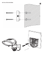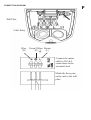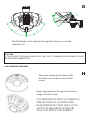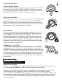
1
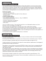
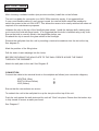
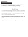
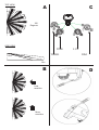
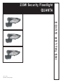
230W Security Floodlight
INSTALLER GUIDE
QUANTA
V4.0 -10/11
IQ-NALP-180-300-D-GR
SECTION ONE
GENERAL INFORMATION
The unit utilises passive infrared technology to detect heat radiation of moving human bodies.
Upon detection, the lamp will illuminate for a user-determined time period. An integral daylight
sensor ensures night-only operation. This unit has a dual light level operation. During darkness
the lamp will illuminate constantly at a user defined light level until it detects movement, then the
unit will switch to full brightness for a user defined time on period.
PARTS INCLUDED
- Luminaire PIR Sensor unit.
- Instruction manual. Please keep safe for future reference.
- Accessory Pack.
- Tungsten halogen bulb
TOOLS & PARTS NEEDED
- 3 core flexible rubber cable (1.0mm² or 1.5mm² "H05RN-F")
- Electric/hand-held drill & bits.
- Terminal or Electrician’s screwdriver
- Large slotted/philips screwdriver
- Wire cutters
Unit is for outdoor use only. Unit must be mounted on a non-flammable surface as a fixed
luminaire, and is not suitable for portable use.
The unit can get very hot during use. Ensure the unit has cooled before handling.
Ensure adequate ventilation space is allowed between the unit and any object above, in front or
to either side of the unit. Suggested space is 0.5m above, 0.3m to either side & 1.0m in front.
Do not attempt to install during wet weather, if you are suffering from nausea or dizzy spells or on
medication with similar side effects.
If in any doubt, consult a qualified tradesperson or electrician.
SECTION TWO
SELECTING THE LOCATION
The motion detector has a number of detection zones, at various vertical and horizontal angles
as shown (see diagram A).
A moving human body needs to cross/enter one of these zones to activate the sensor. The best
all-round coverage is achieved with the unit mounted at the optimum height of 2.5m.
Careful positioning of the sensor will be required to ensure optimum performance. See diagram A
detailing detection range and direction.
The sensor is more sensitive to movement ACROSS its field of vision than to movement directly
TOWARDS (see diagram B). Therefore position the unit so that the sensor looks ACROSS the
likely approach path.
Avoid positioning the sensor where there are any sources of heat in the detection area (extractor
fans, tumble dryer exhausts etc.) including any other light sources such as other security lighting.
Reflective surfaces (ie pools of water or white-painted walls) and overhanging branches may
cause false activation under extreme conditions.
During extreme weather conditions the motion sensor may exhibit unusual behaviour. This
does not indicate a fault with the sensor. Once normal weather conditions return, the sensor will
resume normal operation.
SECTION THREE
INSTALLATION
After choosing a suitable location (see previous section) install the unit as follows:
The unit is suitable for connection to a 240V 50Hz electricity supply. It is suggested that
3-core round flexible cable of 1mm² gauge is used. An internal switch should be installed to
switch the power to the unit ON & OFF. This allows the sensor to be easily switched off when not
required or for maintenance purposes.
Unfasten the clip on the top of the floodlight glass shield. Install the halogen bulb, making sure
not to touch the bulb with bare hands. It is suggested that the bulb is handled using a dry cloth.
Ensure the bulb is correctly fitted in the lampholder before use.
Re-attach the clip to secure the glass shield to the floodlight.
Remove the wall plate from the unit by inserting a terminal screwdriver into the slot at the top,
See diagram D.
Mark the position of the fitting holes.
Drill the holes. Insert wallplugs into the holes.
BEFORE SECURING THE WALLPLATE TO THE WALL PIERCE & PASS THE CABLE
THROUGH THE GROMMET.
Attach the wall plate to the wall. See Diagram E
CONNECTION
Connect the cable to the terminal block on the wallplate as follows (see connection diagram):
NEUTRAL (Blue) EARTH (Green/Yellow) LIVE (Brown) N
L
Ensure that the connections are secure.
To reattach the unit to the wall plate line up the two pins at the top of the unit.
Push the unit against the wall plate and the unit will 'Click' into place. Ensure that the bottom clip
is fully closed to ensure a water proof seal.
See Diagram F.
SECTION FOUR
OPERATION AND TESTING
WALK TESTING PROCEDURE
The sensor will rotate from left to right. Adjust the sensor to point in the desired direction.
See diagram A & H for the different sensor patterns and lens masking.
See diagram C & I for the adjustment controls. Set the Time,Dusk and Dim control as follows :
TIME - Fully anti-clockwise
DUSK - Fully clockwise
Dim - Fully anti clockwise
The unit will now operate during daytime as well as at night, illuminating the lamp for approx.
5 seconds each time. This allows testing to be carried out to establish the best position for the
sensor.
Switch on the mains power. The lamp will immediately illuminate as the unit goes through its
"warm-up" period. After approximately 1 - 2 minutes the lamp will extinguish. Try to remain
outside the detection area during the warm-up period.
Walk across the detection area approx 5 metres from the unit. As you cross a detection "zone"
the lamp will illuminate. Now stand still until the lamp extinguishes (this should take approx. 5
seconds).
Start moving again. As you cross each "zone" the lamp will illuminate.
Repeat the above, walking at various distances and angles to the unit. This will help you to
establish the detection pattern.
A
TOP VIEW
C
180
Degrees
SIDE VIEW
TIME
TIMER
2.5m
LUX
DIM
12m
B
Less
sensitive
More
sensitive
D
INSTALLATION DIAGRAM
E
CONNECTION DIAGRAM
F
Wall Plate
Cable Entry
Blue
(N)
Green/Yellow Brown
(E)
(L)
Connect the mains
cable to N,E & L
connections in the
terminal block
Match the three pins
on the unit to the wall
plate.
G
`8
`8
`8
`8
The floodlight can be adjusted to angle the beam to cover the
required area
CAUTION
IF THE PROTECTIVE GLASS SHIELD FOR THE LIGHT IS DAMAGED OR CRACKED IT MUST
BE REPLACED IMMEDIATELY.
LENS MASKING DIAGRAM
The arrows indicate the front of the
detection area in that section of the
sensor
Engraving indicates the approx detection
range of each section
IT IS IMPORTANT THAT YOU REMOVE
THE SECTIONS TO ACHIEVE THE
REQUIRED DETECTION AREA. IF NO
SECTIONS ARE REMOVE THE PIR
WILL NOT DETECT MOVEMENT
H
ADJUSTMENT KNOBS
TIMER CONTROL MODE
The DUSK TIME setting controls how long the unit remains illuminated
after dusk if the unit is set in TIMER CONTROL MODE. (See section
5). The unit can be set to illuminate between 1 and 8 hours, then it will
SWITCH THE UNIT OFF until Dusk the following evening.
TIME ON ADJUSTMENT
The TIME setting controls how long the unit remains illuminated following
activation & after all motion ceases if the unit is set in AUTOMATIC
MODE. The minimum time (fully anti-clockwise) is approx. 5 seconds,
whilst the maximum time (fully clockwise) is approx. 5 minutes. Set the
control to the desired setting between these limits.
LUX CONTROL
The LUX setting controls the level of darkness required for the unit to
start operating. The setting is best achieved by the procedure below:
Set the DUSK control knob fully anti-clockwise. The unit will now
start operating at dusk. If you require the light to activate earlier, wait
until the ambient light level reaches the level of darkness at which you
wish the lamp to become operative, SLOWLY rotate the control in a
clockwise direction until a point is reached where the lamp illuminates.
Leave the control set at this point.
DIMMER (Hi Lo) CONTROL
The DIMMER setting controls the courtesy light option. The DIMMER
is adjustable from 0% (OFF) to 50% of the light output. When set the
DIMMER will activate the light to the chosen dimmed level at dusk each
evening - it will then stay illuminated at this low level of courtesy lighting
until the sensor is activated. On activation the light will go to full power
for the time period set on the TIME ON adjustment. After the set time
has elapsed the light level will return to the dimmed level until Dawn the
following day.
SECTION FIVE
SPECIAL FUNCTIONS
Manual Override Mode
The light can be switched on for longer time periods by use of the Manual Override Mode. This
can be activated AT NIGHT by using the internal wall switch/circuit breaker.
Switch the internal wall switch/circuit breaker (OFF/ON) within 2 seconds. The unit will now
illuminate continuously until dawn or until is switched back into AUTOMATIC MODE.
To cancel MANUAL OVERRIDE MODE and switch the unit back into AUTOMATIC MODE, flick
the internal wall switch/circuit breaker (OFF/ON) within 1 second. The unit will return to normal
motion sensor operation. Alternatively the MANUAL OVERRIDE MODE will be automatically
cancelled at dawn.
I
SETTING UP FOR AUTOMATIC OPERATION.
When walk tests are complete, the unit can be switched to automatic operation :
The TIME setting controls how long the unit remains illuminated following activation & after
all motion ceases. The minimum time (fully anti-clockwise) is approx. 5 seconds, whilst the
maximum time (fully clockwise) is approx. 5 minutes. Set the control to the desired setting
between these limits.
The Lux control determines the level of darkness required for the unit to start operating. The
setting is best achieved by the procedure below:
Set the Lux control knob fully anti-clockwise. The unit will now start operating at dusk.
If you require the light to activate earlier, wait until the ambient light level reaches the level of
darkness at which you wish the lamp to become operative, SLOWLY rotate the control in a
clockwise direction until a point is reached where the lamp illuminates. Leave the control set at
this point.
At this position, the unit should become operative at approximately the same level of darkness
each evening. Observe the operation of the unit. If the unit is starting to operate too early (ie.
when it is quite light), adjust the control slightly anti-clockwise. If the unit starts to operate too late
(ie. dusk), adjust the control slightly clockwise.
Continue to adjust until the unit operates as desired.
MASKING THE SENSOR LENS
The unit is supplied with a lens mask which allows the option to reduce the range of the sensor.
The lens mask simply clicks over the sensor. When fitting ensure that your chosen option is
facing forwards. The engraved arrow indicates the front of the sensor.
Ensure that the arrow marked on the lens is lined up with the arrow on the sensor. This will then
give an indication of the front of the detection area.
See Diagram H
Engraving on the lens indicates the effect on the detection range each segment will have.
These are 2m, 4m, 8m or 12m.
If no segments are removed then the sensor WILL NOT detect.
The desired range can be achieved by carefully removing the segments then repeating the walk
test after each segment has been removed until the desired detection area is achieved.
SECTION FIVE
TECHNICAL SPECIFICATIONS
Detection Range
Detection Angle
Power Supply
Maximum Switchable Load
Lamp Type
Up to 12 metres
Timer Control
Adjustable 1 to 8 Hrs
Time On Adjustment
5 seconds - 5 minutes
Lux Level Adjustment
Day & night or night only operation
Environmental Protection
IP44 (suitable for outdoor use)
180º
240V ~ 50Hz
300W
118mm Linear Tungsten Halogen 300W max (R7S cap)
Halogen Lamp Replacement
CAUTION
Always handle quartz halogen bulbs with a soft cloth. Do not touch the bulb with your bare hand,
as it will shorten the life of the bulb.
1. Switch off the floodlight. Do not touch the Floodlight while it is in use or still hot. Allow it to cool
(about 5 minutes) before touching it.
2. Replacement bulb type is 240V mains halogen Max 300W R7S cap floodlight bulb.
3. Isolate the mains supply and then unfasten the glass cover.
4. Open the glass cover. The cover is mounted on hinges and will swing open.
5. To remove existing bulb, depress then lift one end of the bulb to remove.
6. Install new bulb by inserting one end first and depressing gently until enough clearance is
gained to seat the other end in the socket. Rotate the bulb to ensure it is properly seated.
7. re-fasten the clip to hold the cover in place.
Warning! In the event of the cover glass shattering, do not replace with normal household glass.
Do not operate without the glass shield in place. If the glass shield is cracked or damaged, it
must be replaced. If the glass is replaced, use only tempered glass of equal thickness
SECTION SIX
TROUBLESHOOTING GUIDE
PROBLEM
SOLUTION
o Lamp stays ON all the time at
night.
The unit may be suffering from false activation. Cover the
sensor lens completely with a thick cloth. This will prevent
the sensor from "seeing" anything. If the unit now switches
off after the set time duration and does not re-activate, this
indicates that the problem was caused by false activation.
The problem may be solved by slightly adjusting the direction/
angle of the sensor head (see previous section).
You may not be allowing the unit time to complete it's
warm-up period. Stand well out of the detection range and
wait (the warm-up period should never exceed 5 minutes).
Occasionally, winds may activate the sensor. Sometimes
passages between buildings etc. can cause a "wind tunnel"
effect.
Ensure the unit is not positioned so as to allow detection
of cars/people using public thoroughfares adjacent to your
property.
o PIR keeps activating for no
reason / at random.
o PIR sensor will not operate
at all.
Check that the power is switched ON at the circuit breaker/
internal wall switch.
Turn OFF the power to the unit and check the wiring
connections as per the diagram (see previous section 3).
Ensure no connections are loose.
Check the lamp. If the lamp has failed, replace. Ensure that
the lamp is seated correctly in the lampholder.
o The PIR sensor will not
operate at night.
o Unit activates during the
daytime
o PIR coverage is poor/sporadic
o Detection range varies from
day to day
The level of ambient light in the area may be too bright to
allow operation at the current DUSK setting. During the
hours of darkness, adjust the DUSK control slowly clockwise
until the lamp illuminates. Refer to previous section for more
details.
The level of ambient light in the area may be too dark for
the current DUSK setting. During daylight, adjust the DUSK
control slightly anti-clockwise. When the lamp extinguishes,
enter the detection area. If the PIR still activates, the setting
is still too high. Repeat the above procedure until the PIR
does not activate when you enter the detection area. Refer to
previous section for more details.
Unit may be poorly located. See previous section - ‘Selecting
The Location’ and re-locate the unit.
PIR sensors are influenced by climatic conditions. The colder
the ambient temperature, the more effective the sensor will
be. You may need to make seasonal adjustments to the
sensor head position to ensure trouble-free operation all year
round.