1
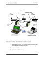
10Mbps SPREAD SPECTRUM
WIRELESS TRANSCEIVERS
M10 Series User’s Manual
Rev. 1
CLARION M10 SERIES
NOTICES
FCC
Models, JX-4000F-A, JX4000F-C, JX4000W-A and JX4000W-C comply with
Part 15 of the FCC Rules. Operation is subject to the following two conditions: (1)
This device may not cause harmful interference, and (2) This device must accept
any interference received, including interference that may cause undesired
operation.
Removing covers from of the radio(s) nullifies the FCC compliance and can be the
cause of spurious transmission, RF noise and out of band transmission levels
above FCC regulations.
Warning
The manufacturer assumes no responsibility for damage caused by interference
due to this equipment.
The information in this document is preliminary. The manufacturer assumes no
responsibility for any errors that may appear in this document.
Ethernet and Ethernet II are trademarks of Xerox.
LANalyzer is a registered trademark of Novell, Inc.
Copyright
Copyright © 1996, Clarion Corporation of America. All rights reserved. No part
of the contents of this document may be transmitted or reproduced in any form or
by any means without the written permission of Clarion Corporation of America.
Patent
United States Patent Number 5,809,060, issued September 15, 1998.
Taiwan Patent Number 073357.
Singapore Patent Number 52170.
South Africa Patent Number 95/1282.
M10 SERIES USER’S MANUAL
PAGE II
CLARION M10 SERIES
TABLE OF CONTENTS
1.
INTRODUCTION __________________________________________________ 1
1.1
Welcome______________________________________________________________ 1
1.1.1 M10 _____________________________________________________________________ 1
1.1.2 M10II ____________________________________________________________________ 1
1.2
Summary of Features ___________________________________________________ 3
1.2.1 FEATURES OF ALL M10 MODEMS __________________________________________ 3
1.2.2 ADDITIONAL FEATURES OF THE M10II _____________________________________ 3
2.
STRUCTURE _____________________________________________________ 4
2.1
Block Diagram_________________________________________________________ 4
2.2
Description of Block Diagram ____________________________________________ 4
2.3
Principles of Operation__________________________________________________ 7
2.3.1 UPLOAD PROCESS ________________________________________________________ 7
2.3.2 DOWNLOAD PROCESS ____________________________________________________ 8
2.3.3 BUFFER MEMORY ________________________________________________________ 9
2.3.4 FORWARD ERROR CORRECTION (FEC) _____________________________________ 9
2.3.5 RE-TRANSMISSION _______________________________________________________ 9
2.3.6 SECURITY ______________________________________________________________ 12
2.3.7 ANTENNA DIVERSITY ___________________________________________________ 12
2.3.8 ANTENNA RECOGNITION (ANTENNA SENSE CIRCUIT) ______________________ 13
2.3.9 ANTENNA POINTING ____________________________________________________ 14
2.3.10 RANGE OF OPERATION________________________________________________ 14
2.3.11 POSITIONING _________________________________________________________ 15
2.3.11.1 Co-Location of M10 Units______________________________________________ 15
2.3.12 CHANNEL ACCESS PROTOCOL _________________________________________ 16
3.
4.
APPEARANCE ___________________________________________________ 17
3.1
Dimensions___________________________________________________________ 17
3.2
Weight ______________________________________________________________ 17
3.3
Front and Rear Panel __________________________________________________ 17
SPECIFICATIONS________________________________________________ 18
4.1
General______________________________________________________________ 18
4.2
Radio _______________________________________________________________ 19
4.3
Network _____________________________________________________________ 20
4.4
Port_________________________________________________________________ 21
4.4.1 MAU PORT______________________________________________________________
4.4.1.1 Pin Assignment ______________________________________________________
4.4.1.2 Absolute Maximum Ratings of the Driver (An7992B) _________________________
4.4.1.3 Transformer (ST7032) _________________________________________________
4.4.2 DC 6.2V PORT ___________________________________________________________
4.4.2.1 Power Requirement ___________________________________________________
4.4.2.2 Power Jack Requirement _______________________________________________
4.5
21
21
22
22
22
22
23
LED Display _________________________________________________________ 24
M10 SERIES USER’S MANUAL
PAGE III
CLARION M10 SERIES
5.
6.
4.6
Emissions ____________________________________________________________ 25
4.7
Environmental________________________________________________________ 25
4.8
Spectrum Mask _______________________________________________________ 26
CONFIGURATION _______________________________________________ 27
5.1
Default Settings _______________________________________________________ 27
5.2
Configuration Commands ______________________________________________ 27
5.3
Configuration Parameters ______________________________________________ 29
COMPLIANCE WITH STANDARDS _________________________________ 33
6.1
MAU________________________________________________________________ 33
6.1.1 BUFFER DELAY _________________________________________________________ 33
6.1.2 FLOW CONTROL ________________________________________________________ 33
7.
RECOMMENDED TEST PROCEDURE ______________________________ 35
7.1
Testing Procedure _____________________________________________________ 35
7.2
SPECIAL FEATURES OF THE M10II___________________________________ 36
7.2.1 INTRODUCTION TO TESTING THE M10II ___________________________________ 36
7.3
Testing Throughput ___________________________________________________ 42
7.3.1 DEFINITION OF THROUGHPUT____________________________________________ 42
7.3.2 SETUP FOR MEASURING THE THROUGHPUT _______________________________ 42
7.3.3 MEASURING PROCEDURE OF THROUGHPUT _______________________________ 43
8.
CUSTOMER ASSISTANCE_________________________________________ 45
9.
GLOSSARY ______________________________________________________ 47
M10 SERIES USER’S MANUAL
PAGE IV
CLARION M10 SERIES
INTRODUCTION
1. INTRODUCTION
1.1 Welcome
Welcome to Clarion’s world of wireless LAN (Local Area Network)
products. The M10 family of products currently include the M10 (Models
JX-4000FA, JX-4000F-C and JX-4000F-S), and the M10II (Models JX4000W-A, JX-4000W-C, and JX4000W-S.
The M10 is a wireless multi-point modem, the M10II is an extension of
this multi-point modem to multi-source address situations, it can
accommodate up to 200 NICs (Network Interface Cards) per network
segment, and maintains its own internal tables.
1.1.1 M10
The M10 is a robust, 10 Mbps (Megabits Per Second) wireless single
address, multi-point modem designed to support wireless connections
across town, across the street or just across the hall for IEEE 802.3 and
Ethernet II (TCP/IP) LANs. It provides all the functionality of a wired
LAN, without the physical constraints of the wire.
The M10 uses state-of-the-art spread spectrum technology, which provides
secure, long-range radio link operations for reliable transmission.
The M10 is compatible with all computer platforms, operating systems and
network protocols. It is pre-configured to operate right out of the box, just
connect the M10 to your existing Ethernet card and use your existing
network software. The M10 functions as an Ethernet Medium Attachment
Unit (MAU) encapsulating the Medium Access Control (MAC) frames
from a standard Auxiliary Unit Interface (AUI) port to form a Radio
Frequency (RF) MAC frame.
The M10 can be connected to a computer, hub or router and can be used to
create innovative LANs by combining existing wired devices with the M10
units without sacrificing speed or accuracy.
1.1.2 M10II
The M10II is the second generation Clarion product in the M10 family.
The M10II offers all the functions and features of the original M10 modem,
as well as providing an important additional advantage to customers. The
M10 SERIES USER’S MANUAL
PAGE 1
CLARION M10 SERIES
INTRODUCTION
upgraded feature of the M10II is the extension of retransmission protocol to
multi-source address situations.
This key new feature of the M10II required substantial development. In
wired communications frames are lost mainly by collisions. However, in
wireless communications frames can be lost by fading, weak signals or
interference. Thus, all radio modems require lower level retransmission of
frames to provide adequate reliability and throughput. The original M10
was designed for connection to a single Ethernet card, either in a
workstation or a router. Both the workstation and the router employ a
single 802.3 source address that the M10 learns and uses for the
retransmission protocol. Thus, when the M10 receives a frame with the
destination address equal to the address of the attached Ethernet card, the
M10 sends the RF acknowledgment frame to the source modem. The
M10II can do this for multiple Ethernet source addresses.
There are two important situations in which the above single-sourceaddress constraint is violated: 802 MAC (media access control) level
bridging and wireless interconnection of 10BaseT hubs. Each of these is
important for general networking, and each presents the modem with
multiple source addresses from the wired side. The M10II maintains a list
of its wired side source addresses, and will acknowledge RF frames
addressed to these. Thus, the key new feature of the M10II is extension of
the retransmission protocol to multi-source-address configurations.
The M10II maintains acknowledgment-address tables, however, it is not a
bridge. For 802-compliant bridging the M10II can be connected to a MAC
bridge, with the MAC bridge providing address tables obtained via the
spanning-tree algorithm.
M10 SERIES USER’S MANUAL
PAGE 2
CLARION M10 SERIES
INTRODUCTION
1.2 Summary of Features
1.2.1 FEATURES OF ALL M10 MODEMS
•
•
•
•
•
•
•
•
•
•
10 Mbps Wireless Multi-Point Modem
Plugs into AUI port of a hub, media converter or router
Simple to install
Adapts immediately without user intervention
High Throughput at the MAC (Media Access Control) layer
Compatible with all IEEE 802.3 and Ethernet II LAN devices, all
operating systems and all protocol stacks
Completely transparent to the network operating system
Secure Direct Sequence Spread Spectrum (DSSS) Technology
Provides all the functionality of wired LANs without the wire
No FCC License is required
1.2.2 ADDITIONAL FEATURES OF THE M10II
• Automatically senses local traffic, builds internal tables and
operates re-transmission and packet filtering protocols
• Accommodates up to 200 NICs per network segment
M10 SERIES USER’S MANUAL
PAGE 3
CLARION M10 SERIES
STRUCTURE
2. STRUCTURE
2.1 Block Diagram
The following is a block diagram of the M10.
Figure 2.1
TX/RX
FIFO
FEC
Encoder/
Decoder
MODEM
RAM
LED
Driver
Main
µP
LED
Front Panel
ROM
Rear Panel
AUI/FIFO
Interface
&
Control
MAU
Driver
MAU
Digital PCB
RF PCB
EXT
ANT
Power
Amp
DC
6.2V
Diversity
SW
TX Lo
Up/
Down
T/R
SW
A/D
Converter
Converter
LNA
Each circuit
Voltage
Regulator
RF
Modulator
Sub
µP
Down
Converter
IF Amp
RF Lo
RX Lo
Local
OSC
SignalFlow of TX & RX signals
Power,C ontrol,D isplay
2.2 Description of Block Diagram
MAU port: The AUI port of an Ethernet device connects to the MAU port
of the M10 through a transceiver cable (AUI cable). The connector type is
physically the same as for a standard MAU.
MAU Driver: Bi-directional driver to the MAU port.
M10 SERIES USER’S MANUAL
PAGE 4
CLARION M10 SERIES
STRUCTURE
AUI/FIFO Interface & Control: provides fast-in-fast-out buffer
management using TX/RX FIFO to minimize the degradation of the
throughput.
TX/RX FIFO: FIFO RAM managed by AUI/FIFO Interface & Control.
FEC Encoder/Decoder: Encoder and a decoder for efficient forward
error correction.
MODEM: generates baseband transmission signals corresponding to the
uploaded data stream or a control data generated by the Main µP. It also
regenerates the received data bit stream corresponding to the output of an
A/D Converter.
RF Modulator: modulates the IF (Intermediate Frequency) carrier by the
output of the MODEM.
Up/Down Converter: up-converts the modulated RF signal of the RF
Modulator to radio transmission signals in the 2.4 GHz band. It also downconverts incoming RF signals of the 2.4 GHz band to IF signals.
Power Amp: amplifies the 2.4 GHz band signals up to transmit power.
RF SW: switches the signal flow from an antenna to a receiver or from the
Power Amp to the antenna.
Diversity SW: switches the antenna to use the internal antenna or the
external antenna, controlled by the Main µP to improve the reception under
the extreme fading environment.
Ext. Ant. port: The external antenna connects to this port. RF signals of
2436 MHz are transmitted or received. The connector type is a SMA
female.
LNA (Low Noise Amplifier): reduces the noise figure of the receiver to
obtain sufficient sensitivity.
Local OSC: provides local signals fed to the Up/Down Converter, to the
RF Modulator and to the Down Converter.
IF Amp: amplifies the IF (Intermediate Frequency) signal of 487 MHz,
enough to be handled by the A/D Converter.
M10 SERIES USER’S MANUAL
PAGE 5
CLARION M10 SERIES
STRUCTURE
Down Converter: regenerates baseband signals from IF signals fed to the
A/D Converter.
A/D Converter: converts analog baseband signals to digital signal stream
for the MODEM.
Main µ P (Microprocessor): controls the signal flow, hardware functions,
and the protocol.
DC 6.2V port: The output of the AC adapter connects to this port. This
voltage is tightly specified. Please contact to Clarion, if you want to use
alternate power sources.
LED: indicates operating situations of the M10. Please refer to
specifications for details.
Sub µ P : controls power fed to each circuit of the M10.
M10 SERIES USER’S MANUAL
PAGE 6
CLARION M10 SERIES
STRUCTURE
2.3 Principles of Operation
2.3.1 UPLOAD PROCESS
The Upload is defined as a data flow from an Ethernet device to the M10.
During Upload, it provides the following:
• Detection of preamble of the Ethernet frame followed by the
frame sync pattern.
• Suppression of the Ethernet preamble and frame sync for RF
transmission. (These portions of the frame are meaningless for
wireless transmission).
• Generation of a Collision signal if an Upload commences
while the AUI interface is busy; generation of the busy
Collision is selected through configuration setup. This enables
the M10 to force the Ethernet card into its exponential back-off
algorithm for flow control. If generation of the Collision is not
selected, then no Collision is generated but Uploads are
ignored.
• Generation, when enabled through the configuration setup, of the
SQE (Signal Quality Error) test signal toward the MAU port.
• FEC-encoding, when FEC is enabled through configuration
setup.
• Generation of header information (RF MAC and RF physical
layer).
• Spread-spectrum carrier sense before transmission, with
preference given to reception. The M10 senses signals after
correlation, meaning that interference, such as microwave ovens
and different kinds of wireless LAN systems, cannot be sensed.
• Data and spread-spectrum modulation onto a carrier of 2.4 GHz
and RF transmission.
M10 SERIES USER’S MANUAL
PAGE 7
CLARION M10 SERIES
STRUCTURE
Figure 2.3.1 shows the encapsulation process described above.
Figure 2.3.1
Standard
802.3 or
Ethernet II
F
Preamble S Dest.
Source
L
or
P
LLC data
CRC
ACROSS MAU INTERFACE
MAC preamble & frame
sync are removed; RF
MAC header is added.
RF MAC Dest.
Header
Source
IN TX FIFO
If FEC coding is
employed, then it
protects everything.
FEC Encoded Frame
OUT OF FEC ENCODER
RF PHY
Header
FROM MODEM
2.3.2 DOWNLOAD PROCESS
The Download is defined as a data flow from the M10 to an Ethernet
device. During Download, it provides the following:
• Detection of and time alignment to received radio signal.
• Demodulation of PHY header and MAC frame.
• FEC decoding when the M10 recognizes that the received frame
is FEC encoded by reading PHY header.
• Checking of 32-bit CRC (generated by an Ethernet card that
Uploaded the frame).
• Conversion of serial stream to bytes for storing in FIFO.
• Regeneration of the Ethernet preamble and frame sync.
M10 SERIES USER’S MANUAL
PAGE 8
CLARION M10 SERIES
STRUCTURE
• Detection of any collision condition for avoiding collision of the
Download to the Upload and signaling of such to the AUI
interface and to the CPU.
2.3.3 BUFFER MEMORY
A data transfer is called an Upload when the Ethernet device conveys a
frame to the buffer memory, and a Download when a frame is conveyed
from the buffer memory to the Ethernet device. The buffer memory is
organized as 16 2-Kbytes FIFOs, each FIFO being independently employed
and capable of storing a maximum-length Ethernet frame of 1518-bytes.
When all buffers are consumed, a Collision signal is generated to force the
Ethernet card into its exponential back-off algorithm for flow control. If
generation of the Collision is not selected, then no Collision is generated
but Upload(s) are ignored.
2.3.4 FORWARD ERROR CORRECTION (FEC)
The nominal transmission mode (uncoded mode) employs modulation
without FEC. The enhanced-robustness mode (coded mode) employs FEC
to overcome irreducible errors due to multi-path propagation condition.
The coded mode and/or selection of a diversity antenna can be selected by
the RF-MAC-level re-transmission protocol.
2.3.5 RE-TRANSMISSION
A re-transmission protocol at the RF MAC layer provides enhanced
reliability. The 32-bit CRC, checked by the 802.3 MAC layer to provide
ultimate data reliability, is also used to support the re-transmission protocol.
Figure 2.3.5 shows a conceptual signal flow diagram of the re-transmission.
The use of MAC-level re-transmission protocol, recommended by 802.11
draft standard, is important for high throughput. Re-transmission via the
level-four transport protocol must be avoided because of the long time-out
typically employed.
M10 SERIES USER’S MANUAL
PAGE 9
CLARION M10 SERIES
STRUCTURE
Prior to the re-transmission, the M10 recognizes and memorizes the source
MAC address of an Ethernet device connected to the M10 through the
MAU port. The Download occurs only when the M10 recognizes complete
matching of the memorized source MAC address and destination MAC
address written in a received radio frame. Once the M10 memorizes the
source MAC address, no update of the source MAC address is performed in
the M10 unless the power turns off. That is, applications that lead to
frequent changing of the source MAC address of the Ethernet frame
coming from plural Ethernet devices through the MAU interface are not
suitable for making the re-transmission effective. In case of such
applications, we recommend the M10 be configured without retransmission.
The re-transmission protocol is based on the recognition of
acknowledgment generated by a M10 that received a radio data frame from
another. A radio frame that carries the acknowledgment is called an Ackframe and effects only the RF MAC level protocol. Contents of the Ackframe never appear at the MAU port. The Ack-frame is transmitted
immediately after the completion of receiving.
The re-transmission is not available for Broadcast-frames because no
Ack-frame can be transmitted for Broadcast-frames (it contains a
destination address of all 1 bits).
Figure 2.3.5 shows two different causes of re-transmission. One is missing
of Ack-frame (Ack #2) and another is missing data-frame (Data #3). In
each case, the M10 #1 recognizes no return of the Ack-frame from M10 #2,
then M10 #1 initiates re-transmission. The M10 #1 recognizes that a
duplicate frame has been received, then M10 #1 filters it out (i.e. download
does not occur). This function is called Duplicate filter.
The duplicate filter is functional only in case a single Ethernet device is
connected to the M10. The function will be updated in the future to make
it available for multiple Ethernet devices.
Duplicate frames that the M10 has not filtered out will be removed by a
function of NOS (Network Operating System). The number of retransmissions is limited to seven (i.e. eight transmission totally).
Accordingly, if no transmission of a frame was successful by the seventh
re-transmission, the successful transmission will depend on the another retransmission function provided by the NOS protocol.
M10 SERIES USER’S MANUAL
PAGE 10
CLARION M10 SERIES
STRUCTURE
The value of the time-out is currently fixed to 300 µ sec. It will be updated
in the future to a user-definable variable to support a range of wireless
links.
Figure 2.3.5
Ethernet Device
#1
M10 #1
M10 #2
Ethernet Device
#2
Data#1
Data#1
Ack
Time-out
Timer
Ack#1
Data#1
Data#2
Data#2
Ack
Time-out
Timer
Ack#2
Data#2
×
Data#2
Data#3
Data#3
Ack
Time-out
Timer
Data#2 (N
ote)
×
Data#3
Data#3
× indicates missing of radio frames.
Note: No duplicate frame is downloaded in case of single Ethernet
device is connected to the M10.
M10 SERIES USER’S MANUAL
PAGE 11
CLARION M10 SERIES
STRUCTURE
2.3.6 SECURITY
Security is a great concern with any data transmission system. Security in
wireless data systems may be of even greater concern because of the
leakage of transmitter waveforms beyond the intended receiver sites. The
M10 offers excellent security without incorporating conventional
cryptography. Of course, the user always has the option to add
conventional data encryption technology to the most critical applications.
Most commercial spread spectrum manufacturers use fixed spreading codes
in their products. The M10 radio, with Direct Sequence Spread Spectrum
(DSSS), uses continuously changing, pseudo-random spreading codes, in
which each symbol is encoded with a different spreading code.
Furthermore, the user may select from 216 (64k) different sequences to
determine the order in which the spreading codes are used; this provides
excellent security against eavesdropping by unintended parties.
The sequences can be selected through configuration procedure provided by
the M10.
2.3.7 ANTENNA DIVERSITY
The M10 also offers additional robustness via the Antenna-selection
diversity upon re-transmission.
The M10 (models JX4000F-A and JX4000W-A) is equipped with an
internal antenna and an external antenna port for the attachment of your
FCC approved antenna for longer distance links. The external antenna port
uses a standard female SMA connector with Antenna Sense Circuit for use
with a FCC approved antenna. The user can purchase FCC approved
antennas kits from HyperLink (see section 8. Customer Assistance for
contact information).
If the user selects Enable of the diversity in the configuration setup, the
M10 selects the antenna for each transmission. The antenna used for the
transmission is memorized and used for the next transmission of a new
uploaded frame.
M10 SERIES USER’S MANUAL
PAGE 12
CLARION M10 SERIES
STRUCTURE
2.3.8 ANTENNA RECOGNITION (ANTENNA SENSE CIRCUIT)
M10 uses a standard SMA connector for the attachment of external
antennas. Although there is a standard SMA connector only
Clarion approved antennas will work due to the Antenna Sense
Circuit.
Antenna Sense Circuit is an electrical verification that the
attached antenna is FCC approved for use with the M10. If another
antenna is attached the M10 will not transmit.
IMPORTANT
Antenna Sense Circuit activates only at POWER UP
The antenna sense circuit electronically senses the attached antenna
when the M10 is first turned on. If an antenna is attached after the
M10 has already powered up the antenna will not be recognized.
You must switch the M10 off and back on to activate the antenna.
WARNING! The external antenna port outputs dc voltage up
!
to +5 Volts for antenna recognition. If using measuring
equipment, please check allowed dc input voltage of the
equipment.
M10 SERIES USER’S MANUAL
PAGE 13
CLARION M10 SERIES
STRUCTURE
2.3.9 ANTENNA POINTING
It is important to properly point external directional antennas at the
time of installation. We suggest that the user employ the Traffic
program (included in the Software Utility Kit Diskette) to assist in
the installation of directional antennas.
We suggest that the installer follow these steps as part the external
directional antenna set-up process:
1. Connect a laptop computer to the MAU port of the M10. An
active IPX/SPX stack is required on the computer.
2. Install the Traffic Program (from Utility Software Kit
Diskette).
3. Point both directional antennas in the general direction of
each other.
4. Initiate network data traffic between the 2 sites.
5. Alternatively at both antenna sites, dither the pointing of the
directional antennas until maximums in network traffic
throughput are observed.
6. As a final step, find the angular range (both horizontally and
vertically) over which the maximum traffic throughput can be
maintained for the first antenna. Once this angular range is
obtained, lock the position of the first antenna in the center of
this range. Then repeat this process at the other antenna site,
and lock that antenna in position.
2.3.10 RANGE OF OPERATION
Using the internal antenna (models JX4000F-A and JX4000W-A
only) the operating range is 100-200 meters of coverage. The range
of operation will decrease if the M10 is positioned behind large
metal objects, such as file cabinets, safes, storage cabinets, metal
walls or walls containing foil-backed insulation.
The outdoor operating range with high gain antennas in line-of-sight
operation is up to 5 miles. With special amplifiers purchased from
HyperLink (see section 8. Customer Assistance for contact
information) the user may reach up to 20 miles in line-of-sight
operation.
M10 SERIES USER’S MANUAL
PAGE 14
CLARION M10 SERIES
STRUCTURE
2.3.11 POSITIONING
Proper positioning of the M10 units will increase the range of
operation and the ability of the units to
communicate. It is important to position the
M10 units out in the open and away from any
large metal objects such as file cabinets, safes,
storage cabinets, metal walls or walls
containing foil-backed insulation.
To reduce the risk of the unit overheating, do not
place the M10 under boxes, papers or anything that
may reduce airflow.
If you are using the units in an office with metal cubicle walls it will
increase operating range if the units are placed above the cubicle
wall height.
The use of microwave ovens during transmission may reduce data
throughput by as much as a factor of two.
2.3.11.1 Co-Location of M10 Units
If two or more M10 units are co-located at one site, maximum traffic
throughput rates to remote sites may be reduced, especially if the
user is relying on the internal antennas.
The M10 units operate on a single frequency channel. If one M10
unit is transmitting to a remote site while a second M10 is
attempting to receive data from a second remote unit, the
transmitting M10 will normally block receipt of messages by the
receiving M10.
Traffic throughput rates can be improved by providing enhanced RF
isolation between the co-located units at a site. This is best
accomplished by using correctly orientated directional antennas at
each site. Further improvement in throughput can be expected if the
external directional antennas can be further isolated to reduce RF
leakage. This can be accomplished by increasing the physical
separation between the antennas or by locating the antennas in such
M10 SERIES USER’S MANUAL
PAGE 15
CLARION M10 SERIES
STRUCTURE
a manner that direct RF leakage between the two antennas is reduced
by an intervening metal object or shielding wall.
2.3.12 CHANNEL ACCESS PROTOCOL
The M10 provides for adaptive P-CSMA1 by using a sequence of P values.
These are loosely tied to the transmission attempts, in that the P values in
the sequence correspond to the attempt number, but any successful receive
resets to P0 for the next attempt; if that attempt fails, the sequence of P
values is resumed according to which attempt is in progress. (P is a power
of two, up to 256.)
1
On Ethernet both carrier sensing and collision detection are simple processes. For any
radio channel the ability to detect collisions is lost; in addition, for a spread-spectrum
system with changing codes (for security) the ability to perform carrier sensing is
limited to acquisition of the preamble portion of a transmission. The channel-access
protocol (CAP) employed in the M10 is called P-persistent CSMA.
M10 SERIES USER’S MANUAL
PAGE 16
CLARION M10 SERIES
APPEARANCE
3. APPEARANCE
3.1 Dimensions
2 inches (W) x 4.7 inches (H) x 6.5 inches (D)
3.2 Weight
14 ounces
3.3 Front and Rear Panel
Figure 3.3
Internal antenna
(inside the top
cover)
MAU port
MAU LED
TX LED
External antenna port
DC 6.2V port
RX LED
Power LED
Power
FCC Certification label
(bottom)
M10 SERIES USER’S MANUAL
PAGE 17
CLARION M10 SERIES
SPECIFICATIONS
4. SPECIFICATIONS
4.1 General
Frequency Range
Carrier Frequency
Type of Emission
Chip Modulation
Processing Gain
Communication Method
Channel Access Method
Type of Interface
Datalink Interface
Network Addressing
RF MAC Protocol
Network Topology
Note 1
2
: 2400-2483.5 MHz ISM band
: 2436.07 MHz
: Direct Sequence Spread Spectrum
: BPSK, 32 Mcps
: 12dB (Nominal)
: Half Duplex
: SS-P-CSMA2
: MAU (driven by AUI)
: IEEE802.3 or Ethernet II MAC
: derived from attached NIC
(Note-1)
: Radio encapsulation of IEEE802.3
or Ethernet II MAC frame.
: Peer to peer
JX-4000F-S has own MAC address for configuration of
operating parameters. JX-4000F-S also memorizes single
MAC address of attached Network Interface Card(s) for retransmission protocol.
Spread Spectrum p-persistent CSMA
M10 SERIES USER’S MANUAL
PAGE 18
CLARION M10 SERIES
SPECIFICATIONS
4.2 Radio
Table 4.2
Parameter
Min.
Carrier Frequency Stability
Max.
-10
Peak Power Density
-6
Unit
Note
+10 PPM
Data Rate
10
+1.0 dBm/
MHz
Mbps
Sensitivity
-85
-81 dBm
2436MHz
1.4
2.3
2436MHz+10MHz
1.9
3.2
2436MHz+20MHz
2.2
3.9
2436MHz+30MHz
2.6
4.1
VSWR
1.
Typ.
-2
V/V
1
2
3
Measured by spectrum analyzer with RBW=1MHz, VBW=10Hz. Total transmit power can be
calculated by adding 16.0±0.6 dB to the Peak Power Density. Accordingly, typical total
transmit power is 14 dBm.
2. Input power at which the throughput without re-transmission degrades to 75% of typical
throughput (See Figure 4.2).
3. For receive and transmission.
Figure 4.2
Throughput (Mbps)
10
H1
H2
H1 : typical throughput
H2 = 0.75 ∗ H1
Pi : Sensitivity
Pi
M10 SERIES USER’S MANUAL
Received input power
PAGE 19
CLARION M10 SERIES
SPECIFICATIONS
4.3 Network
Table 4.3
Parameter
Min.
Typ.
Max.
Unit
Note
Throughput without Re-transmission
7.9
8.8
Mbps
1
Throughput with Re-transmission
6.8
7.6
Mbps
1
Boot up Time
5.5 sec
2
1 10 (Mbps) × Measured Average Utilization (%) under the condition of two units connected by
cable through 60 dB attenuator and uni-directional data flow.
2 Time for self checking and stabilization of radio operating point. If AC power is switched,
additional time must be considered because of its time constant.
M10 SERIES USER’S MANUAL
PAGE 20
CLARION M10 SERIES
SPECIFICATIONS
4.4 Port
4.4.1 MAU PORT
4.4.1.1 Pin Assignment
Table 4.4.1.1
D T E (AUI)
PIN
3 Data out+
10 Data out11 Shield
5 Data in+
12 Data in4 Shield
7 Control out+
15 Control out8 Shield
2 Control in+
9 Control in1 Shield
6 Voltage common
13 Voltage+
14 Shield
Shield Protective Ground
M 10 (M A U )
Data Flow
2
1
2
1
NC
1
2
1
NC
1
PIN
3 Data in+
10 Data in11 Shield
5 Data out+
12 Data out4 Shield
7 Control in+
15 Control in8 Shield
2 Control out+
9 Control out1 Shield
6 Voltage common
13 Voltage+
14 Shield
Shield Protective Ground
1000pF
JX-4000F-A
Chassis Ground
M10 SERIES USER’S MANUAL
PAGE 21
CLARION M10 SERIES
SPECIFICATIONS
4.4.1.2 Absolute Maximum Ratings of the Driver (An7992B)
Table 4.4.1.2
Parameter
Min.
Typ.
Max.
Unit
DC Voltage Applied to Outputs
- 0.5
+ 5.0 V
DC Voltage Applied to Inputs
- 6.0
+ 12.0 V
DC Logic Input Voltage
Note
+ 5.5 V
DC Output Current, into Outputs
100 mA
DC Input Current (Logic)
± 30 mA
4.4.1.3 Transformer (ST7032)
Table 4.4.1.3
Parameter
Min.
Typ.
Common Mode Standoff
Max.
Unit
Note
2000 Vrms
Rise Time
3.0 ns
4.4.2 DC 6.2V PORT
4.4.2.1 Power Requirement
Table 4.4.2.1
Parameter
Supplied DC Voltage
1.
Min.
6.00
Typ.
6.20
Max.
Unit
Note
6.85 Vdc
1
1
Ripple and Spurious
30
100 mVp-p
Current Consumption (TX)
1.6
2.0 A
Current Consumption (RX)
1.1
Measured at current draw of 1.8 A.
M10 SERIES USER’S MANUAL
PAGE 22
CLARION M10 SERIES
SPECIFICATIONS
4.4.2.2 Power Jack Requirement
Ground
Positive pin
Pin length
:
:
:
5.5 mm outer diameter
2.1 mm inner diameter
10 mm
2.1
Positive
5.5
Ground
10
(mm)
Figure 4.4.2.2
Note
Ground is connected to a chassis of the M10.
M10 SERIES USER’S MANUAL
PAGE 23
CLARION M10 SERIES
SPECIFICATIONS
4.5 LED Display
There are four LED indicator lights on the front panel of the M10 (Figure
3.3). These lights help the user to understand the status of the M10. The
Lights are as follows:
MAU -Flickers for Upload or Download of a
Connected AUI.
TX - Flickers whenever a frame is RF transmitted
RX - Flickers whenever a frame is RF received
POWER - Indicates the M10 is turned on
Table 4.5
Label
MAU
Color
Green
Description
Indicates MAU signal (upload or download) is active. (Note-1)
During the power-up cycle, it blinks on and off slowly five
times in approximately one second to indicate that the firmware
has passed its integrity
2. After normal power-up cycle, it indicates radio transmission.
(Note-1)
3. During the firmware-upload cycle ; refer description
attached on the new firmware.
1.
Indicates radio signal detection. (Note-1)
RX
Green
2. Sometimes flashes even if no true signal is received, because of
optimized false alarm rate.
1. It turns on just after applying the power to indicate activation
Power
Red
of the unit.
2. It will not illuminate continuously if there is unsuitable supply
voltage.
Note-1 : The turn-on period is very brief. The intensity of the flickering is proportional to the
throughput of traffic.
TX
Red
1.
M10 SERIES USER’S MANUAL
PAGE 24
CLARION M10 SERIES
SPECIFICATIONS
4.6 Emissions
Non-intentional
:
Intentional
:
FCC part 15 (Radio Frequency Devices)
Subpart B (Unintentional Radiator)
Class A digital devices & peripherals
FCC part 15 (Radio Frequency Devices)
Subpart C (Intentional Radiator)
4.7 Environmental
Operating Temperature Range
Specification Guaranteed
Operation Guaranteed
Storage Temperature Range
:
:
:
Humidity
:
Vibration
:
M10 SERIES USER’S MANUAL
0ºC ~ +40ºC
-10ºC~+50ºC
-20ºC ~ +60ºC
0% ~ 90%
0.4 G (peak to peak)
PAGE 25
CLARION M10 SERIES
SPECIFICATIONS
4.8 Spectrum Mask
Spectrum of transmission signal from external antenna port of JX-4000FS complies with spectrum mask shown in Figure 4.8. The example shows
acceptable spectrum. This specification is applied at room temperature.
Figure 4.8
Measurement conditions of the spectrum:
1.
Using spectrum analyzer connected directly to external port of JX-4000F-S.
2.
Spectrum Analyzer Settings
l
Center Frequency
:
2436.070 MHz
l
Span
:
150 MHz
l
Reference Level
:
20 dBm
l
Detection
:
Sample
l
RBW
:
1MHz
l
VBW
:
10Hz
l
Scale
:
10 dB/div
l
Sweep Time
:
Auto
3.
Using unit of dBm/MHz for power density.
4.
Using continuous spreading transmission with pseudo-random data initiated by
sending special command to the M10 through MAU port3.
3
M10 SERIES USER’S MANUAL
PAGE 26
CLARION M10 SERIES
CONFIGURATION
5. CONFIGURATION
The M10II units are pre-configured to operate right out of the box. There
are also a variety of options that the user can change to adapt the M10II to a
specific situation.
The configuration software is pre-loaded into an internal EEPROM
(Electrically Erasable Programmable Read-Only Memory) in the M10II.
For updates to this software please see section 8. Technical Information.
5.1 Default Settings
The default settings that the M10II is shipped with are as follows:
• Acknowledging is enabled (one ACK per packet)
• Transmit filtering is turned on
• Download filtering is turned on
• Aging time is set to 5 minutes
• Loop Detection is on
• Static Table is uploading is set to off
• Professional Addressing Mode is off
5.2 Configuration Commands
Included with the radio is a diskette that contains MIImqry.exe and
Tmshow.bat. MIImqry is like M10query but includes the M10II settings of
filtering and aging. Tmshow.bat allows the user to read the table that is
stored internally in the M10II at the time of issuing the command. They
both keep log files. Both of these programs can be issued remotely. By
using these the complete configuration and stored table of any radio in the
network can be read from any location in the network. You only need to
know the MAC ID of the radio you are trying to query. Both commands
continue to issue once per second until there is a response or until a key is
hit.
The following utilities will be included on diskette for the M10II. Typing
the name followed by a question mark will show the usage syntax.
• MIImqry.exe allows monitoring of the configuration.
M10 SERIES USER’S MANUAL
PAGE 27
CLARION M10 SERIES
CONFIGURATION
• Tmshow.exe will read out the table that is stored in the M10II at
the time of issue.
The new configuration commands for controlling the M10II are as follows
(can use with the send or sendm10 commands):
CONFigFe1, CONFigFe0 turns M10II mode on/off respectively.
When M10II is off the radio does not operate. This command is
stored in non-volatile memory and takes immediate effect.
CONFigFt1, CONFigFt0 turns transmit filtering on/off. (Default is
on) This command is stored in non-volatile memory and takes
immediate effect.
CONFigFd1, CONFigFd0 turns download filtering on/off. (Default
is on). This command is stored in non-volatile memory and takes
immediate effect.
CONFigFaxx, xx== 0 to 60, sets aging value. xx=0 turns aging off.
(Default is 5 min.) This command is stored in non-volatile memory
and takes immediate effect.
CONFigFr1, CONFigFr0 turns remote commands on/off
respectively (Default is off). This command is stored in non-volatile
memory and takes immediate effect.
CONFigFs1, CONFigFs0 (Static table command) turns table
maintenance on or off respectively; default is on. Table maintenance
is defined as table insertions, deletions, and aging. This command is
used if the OEM is using an 802.1d bridge or other table-building
device that they prefer over our automatic table-building protocol.
The OEM must upload the table into the M10II using the
CONFigFw command followed by packets containing the table in
the format described below. Then the data-link-level
acknowledgment protocol will operate with the microsecond-scale
response that only the radio itself can provide, but based on the
tables provided by the user. All filtering can still be optionally
applied. This command is currently volatile and should be issued
after each power cycle or prior to each table revision. When using
this, the OEM can shut off the M10II loop sense protocol since the
table generation device will have that built in. An ANSII C program
M10 SERIES USER’S MANUAL
PAGE 28
CLARION M10 SERIES
CONFIGURATION
that will convert an ASCII address list to the proper internal format
is available from the web site. Also, the required format is available
if you want to generate your own program to do this. In order to
keep remote commands enabled when the OEM is uploading a table,
the MAC ID of the radio must be included in the uploaded table,
since the remote commands rely on having it there.
CONFigFl1, CONFigFl0 Turn the proprietary loop-sense/blocking
function on or off respectively (Default is on). If the static table
command is used, the loop-sense/blocking feature is not generally
needed because this function is accomplished in the device
generating the table. This command is stored in non-volatile
memory and takes immediate effect. (Even though the static-table
command is volatile and must be re-issued upon power-cycling).
CONFigFw prepares the M10II to receive a table to use in place of
its own. The table maintenance will continue to operate on the
uploaded table, adding to it and deleting from it unless the static
table command is issued. The format used for the packets
containing the table is available from the web site. In order to keep
remote commands enabled when the OEM is uploading a table, the
MAC ID of the radio must be included in the table, since the remote
commands rely on having it there. (The radio MAC ID is normally
entered into the table when the radio is turned on).
CONFigFpXX, where XX is a decimal value 0-32. If 00 is entered,
professional mode is turned off. There are 32 possible addresses.
The default is that this mode is off. This command is stored in nonvolatile memory and takes immediate effect. Example: send
CONFigFp10 00606f01E765.
CONFigFn1, CONFigFn0 selects 802.3/802.2 respectively as the
packet response for configuration frames. CONFigFn1 is the default
as it was in the M10.
5.3 Configuration Parameters
The following is a list of the configurable parameters of the M10:
M10 SERIES USER’S MANUAL
PAGE 29
CLARION M10 SERIES
CONFIGURATION
Table 5.3 Configurable Parameters
Parameters
AUI Busy Collision
Possible Values
1/0 (i.e. On/Off)
Default
On
SQE Test
1/0 (i.e. On/Off)
Off
Download with CRC
error
1/0 (i.e. On/Off)
Off
FEC Sequence on retries
P-CSMA slots
Try #
Available
configuration
FE
1
FEC on or off for
each trial
Off
2
3
4
5
6
7
8
Try #
1
Available
configuration
P-CSMA slotnumber P of 1 to
8 for each trial.
M10 SERIES USER’S MANUAL
On
On
On
On
On
On
On
23456788
Remarks
Used for flow control on wired
side. ON causes assertion of
collision signal if a frame
upload is attempted when all 8
upload buffers are full.
OFF means do not assert
collisions if 8 packet upload
buffers are full.
ON means there is a brief
assertion of collision signal after
frame ends.
OFF means no signal after
frame
If “Download with CRC error”
is ON, M10II downloads all
frames regardless of CRC
check.
OFF means block CRC failures.
The FEC mode is selected as
1/0 (i.e. On/Off) for a particular
transmission attempt. (There are
a maximum of 8 tries per
packet. The first transmission
and up to 7 re-transmissions).
The number of ~15us slots that
are used as the range of the
uniformly distributed wait
interval before transmitting in a
CSMA protocol. This is
commonly known as the
backoff but in actuality, is only
the range of the possible
backoffs. The number set in
config is the binary exponent.
2
PAGE 30
CLARION M10 SERIES
Parameters
P-CSMA slots
(continued)
CONFIGURATION
Possible Values
2
3
4
5
6
7
8
Number of tries of
transmission
Hardware
Address Checking
Security Code Channel
Duplicate Filter
Search Code
Antenna Diversity
4
Default
3
1–8
4
5
6
7
8
8
8
1/0 (On/Off)
Off
00001h ~ FFFFh
2D1Bh
1/0 (On/Off)
On
44BCh, A0DCh, D223h, 0A76h,
425Ch, 23A4h, 245Ch, A243h
1/0 (On/Off)
44BCh
Off
Remarks
For example, a value of 3 means
there are 8 possible slots that a
queued transmission can begin
in as measured from the end of
the previous transmission. The
transmission has a 1/8
probability of occurring in any
of those slots.
“1” means no re-transmission
Acknowledgments are sent for
received frames with matched
destination address only when
this is On, and are not
dependent on the address when
this is Off. The hardware
register is loaded with the
address of either the first source
it sees on the wired side after
connection, or, an address that
can be manually set.
Spreading code changes pseudo
randomly by a sequence defined
by this code channel.
If this switch turns on, received
duplicate frames are discarded4.
If it is Off, duplicate will not
prevent a download.
Search Code is a PN code used
for initial acquisition They are
chosen for good performance
and provide
OFF means that the antenna
first “Antenna Selection” setting
chooses a particular antenna.
ON means that the “Antenna
Selection” setting toggles the
antenna choice or leaves it alone
based on the setting for any
particular transmission attempt
for a packet.
Duplicate filter function is available in case of one to one connection only. It means that if two or
more modems are connected to a modem, duplication cannot be avoided.
M10 SERIES USER’S MANUAL
PAGE 31
CLARION M10 SERIES
Parameters
Antenna Selection
RF Address
Use default MAC ID
Possible Values
1/0 (External/Internal)
Derived from attached NIC
Or set manually with CONFigRf
command.
MAC Address
(00606FXXXXXX)
or
Clarion Null Address
(00606F000000)
ACK time-out
0xx6E to 0xxFE
M10 SERIES USER’S MANUAL
CONFIGURATION
Default
FF
(= External
with
Diversity set
to OFF)
Remarks
This parameter must be set to
‘External’ absolutely because
no internal antenna is provided
with JX-4000. Otherwise it
behaves similar to the FEC
mode where a 1 toggles the
antenna choice and a 0 leaves
the choice for a transmission
attempt.
RF address is used on RF
reception by the JX-4000
determine whether to send
ACK, and at the transmitter to
recognize its ACK. It is not
used if ‘Address Checking’ is
off.
Null Address Upload address is used for
configuration and firmware
upgrade only. Each JX-4000 has
its own unique 12-hex-digit
MAC ID that is used as default
Upload Address. However, one
can select Clarion Null Address
‘00606F000000’ as Upload
Address for convenience.
0xx6E
Can be selected by steps for
(~330us)
various environments of
applications. The longer link
range requires the longer ACK
time-out. Three (3)
microsecond time resolution.
PAGE 32
CLARION M10 SERIES
STANDARDS
6. COMPLIANCE WITH STANDARDS
6.1 MAU
While the M10 has been designed to appear electrically as a standard MAU,
it is executing a medium-access protocol appropriate for the wireless
medium. As a result, some of its behaviors are not reflected in a wiredmedium MAU, and the transparency to the wired-medium MAC in the
attached computer or bridging device cannot be absolute. MAUs for wired
networks have no internal storage; they operate with negligible delay
relative to the signals at the AUI/MAU interface.
Because the MAC software in the attached computer is executing a
protocol appropriate for the wired medium, and the M10 must employ a
protocol appropriate for the wireless medium, the M10 stores frames in
buffers in order to isolate the (wired and wireless) media.
This results in important differences from conventional 802.3 MAUs; these
include buffer delay as well as the need for RF re-transmissions and for
flow control.
6.1.1 BUFFER DELAY
The protocol operating over a M10 link must anticipate a delay of two
frames in each direction. When a frame is offered from the AUI port, first
it is saved in a buffer; subsequently the frame is transferred over the RF
channel to a receive buffer in the destination M10; only then is the frame
downloaded to the destination AUI port.
This need not limit throughput if the transport protocol properly anticipates
the delay. If the protocol waits for each frame to be acknowledged, then
the throughput achieved will be very low due to the excess delay.
However, if a burst mode is used, then the effect of the delay can be made
negligible. This effect can be readily demonstrated using, for example,
Perform 3®.
6.1.2 FLOW CONTROL
When no buffers are available for UPLOAD of AUI frames to the M10,
some action is required. The M10 may:
M10 SERIES USER’S MANUAL
PAGE 33
CLARION M10 SERIES
STANDARDS
1. Invoke flow control (default for the M10 connected to an AUI port),
by using the COLLISION signal to force the Ethernet card into its
exponential back-off algorithm. Because there are eight UPLOAD
buffers, this flow control can always maximize RF throughput even
though the attached device may delay re-offering of frames.
2. Ignore UPLOAD frames when no UPLOAD buffer is available,
this may be required when the M10 is connected to multiple
computers (e.g., via a hub) which might be disrupted by excessive
collision indications. However, ignored frames will incur a large
delay for retransmission by the level-4 transport protocol (TCP,
IPX), or may not be re-offered at all for datagrams (UDP, SPX).
Although using the COLLISION signal for flow control is the
default, the user must make an informed selection between these two
possibilities based upon network topology, acceptable link behavior,
and the requirements of the application software.
M10 SERIES USER’S MANUAL
PAGE 34
CLARION M10 SERIES
TESTING
7. RECOMMENDED TEST PROCEDURE
7.1 Testing Procedure
To test the units connect two M10s (or two M10IIs), one to each of two
previously isolated network segments, leaving all settings at the factory
default values.
1. Make an inter-segment file transfer and observe the LEDs on the M10II
units. The upload (MAU) and transmit (TX) lights on the sending unit
will turn on brightly. The receive (RX) and download (MAU) light on
the receiving unit will also turn on brightly. The transmit light (TX) on
the receiving radio and the receive light (RX) on the sending radio will
turn on dimly due to the acknowledgments. If other combinations of
LEDs occur, there may be something wrong. There should be expected,
bursts of traffic and dead time in any network file transfer and this
should not indicate a problem.
2. Next make a local file transfer between NICs on a single segment. You
will see the upload light (MAU) come on but not the transmit light (TX)
on the sending unit, and you should see no receive lights on the other
unit. You can simultaneously do a local file transfer on each segment
and if you attach LAN analyzers to each, you will see that each unit
simultaneously achieves wired speed.
3. Now attach a third segment with a third M10II. When you do an intersegment file transfer, the LEDs will be the same as before for the
intended receiver, but the third M10II will show only a receive light, not
a download light nor a dim transmit light. In this case, the M10II that
has the intended NIC attached will acknowledge and download the
packets. The other M10II will receive the packets but will not respond
with acknowledgments, and not download. You can also try three
simultaneous local file transfers, and you will see that each achieves
wired speed. You may also wish to try an inter-segment file transfer
between two of the segments and a simultaneous local file transfer on
the third segment.
M10 SERIES USER’S MANUAL
PAGE 35
CLARION M10 SERIES
TESTING
7.2 SPECIAL FEATURES OF THE M10II
7.2.1 INTRODUCTION TO TESTING THE M10II
The standard M10 is a single address wireless modem, the M10II has been
expanded to accommodate multi-address situations. The M10II maintains
internal acknowledgment-address tables. This extension of retransmission
protocol to multi-source address situations requires further information to
understand the operation of the M10II:
1. To test the M10II it is suggested that you connect two M10II units, one
to each of two previously isolated network segments. As the normal
traffic is generated on each segment the internal M10II table is
automatically built up on the packet transmissions of each NIC. Only
one transmission is required to create a table entry for a NIC. The
source addresses of the traffic are used to build and maintain the table
and the tables are referenced by the destination addresses of the traffic
to determine whether or not the intended receiving NICs are attached to
a particular M10II. The M10II units are shipped with the following
defaults: acknowledgment is enabled, transmit filtering is turned on,
download filtering is turned on, aging time is set to 5 minutes, loopsense is on, and professional addressing mode is off. The following is a
brief description of these features.
a) M10II acknowledging enabled. This is the main M10II feature, it
refers to the data-link level re-transmission protocol. It means
that if a destination address of an intended NIC is in the local
table of the M10II, that radio will acknowledge the packet from
within the radio firmware with microsecond response time. This
feature creates a reliable link out of a wireless connection.
Without it, the burden on common transport-level protocols
would be too great to obtain substantial throughput.
b) Transmit filtering on. When this feature is activated local traffic
will remain local. If a packet generated on a segment is
addressed to a NIC on the same segment, the M10II will not
transmit that packet. The result is that local bandwidth is
preserved and the radio must only support the total inter-segment
bandwidth. Therefore many segments, each with 10 Mbps local
M10 SERIES USER’S MANUAL
PAGE 36
CLARION M10 SERIES
TESTING
bandwidth, can be connected with a 10 Mbps backbone since
each packet is not necessarily transmitted. Without it turned on,
the bandwidth of any local segments is shared by the NICs on
other remote segments, since each packet that is generated on
another segment is transferred to the local segment and vice
versa. Transmit filtering also provides added security because
local server traffic is not exposed to other segments.
c) Download filtering on: This feature can be thought of as the
converse of transmit filtering. The M10II with this enabled will
not download to its network segment, a packet that it receives if
the destination is not on its local segment. Of course, all packets
on the same code channel will be received by the M10II, and
their CRC will be checked, prior to the address being examined.
d) Aging = 5 minutes. This default value is the same as in most
bridges. If a NIC is shut down, the aging setting is the time that
it takes to passively decide to remove the entry from the local
table. As long as a packet is sent from a NIC more often than
this setting, the entry will remain in the table. Most network
operating systems will normally send out keep-alive or sense
packets more often than once per minute. The penalty for being
deleted from the table is minimal; it takes about 20 ms
(milliseconds) after a packet is transmitted for the entry to be
placed into the table. Also, if a NIC is moved to another
segment, the transmissions that it generates from another M10II
will force the instant deletion of the NIC address from the table
of the first M10II. If transmissions from the moved NIC are not
received, the aging will cause the NIC to be deleted after the
aging time as measured from the last packet that the NIC
generated while it was still local. The table is volatile and
cycling the power will delete the table.
e) Loop detection. The M10II has an optional capability for
detecting and blocking network loops. A loop is a network
connection that allows a packet to be regenerated, and can occur
with any wired or wireless network device. An example of a
loop is when two radios are inadvertently connected to the same
network segment, and they are on the same code channel, then a
packet that is uploaded and transmitted by one radio, is received
and downloaded by the second radio, which creates a packet to
M10 SERIES USER’S MANUAL
PAGE 37
CLARION M10 SERIES
TESTING
be uploaded by the first one again. If the loop is allowed to
persist, the packet will be regenerated indefinitely. Instead of
allowing this to happen, all M10IIs will first start in the blocking
mode when they are powered on (if loop detection is enabled).
The blocking mode prevents any packets to be transmitted and
only loop-sense packets to be downloaded. If a loop is detected,
the M10II will block traffic until the loop is eliminated. If after
trying for a few seconds, the radio does not sense a loop, it will
exit blocking mode and proceed with a normal boot cycle. After
that, an attempt to sense loops will be made at 3 second intervals,
and steals 2ms of traffic time each 3 seconds in order to operate.
Since a loop can be created while reconfiguring the wired
network the detection process will occur indefinitely. After the
initial boot, there will be 2 one-second intervals, each signaled by
a pair of LED flashes, and then 5 LED flashes if there is no loop
found. If there is a loop, then the radio will enter a blocking state
where no packets will be transmitted or downloaded, and the
radio will continue to sense the loop at 3-second intervals. After
4 intervals without seeing a loop, the blocking state will be
terminated, the LED will indicate this by flashing 5 times. There
may be additional delays in high traffic conditions (i.e. > 65%
wired side utilization, continuously over the 3 second time
periods).
When in the blocking state, a blocking-message packet is
downloaded to the wired side just prior to the loop test packet.
The blocking message is addressed to broadcast (all Fs), and the
source address is the active address. The loop test packet is
addressed to the sensing M10II’s own MAC_ID independent of
the active address. The source address is the active address.
Therefore, it will have the same source and destination address if
the CONFigAs1 command has been issued.
If you power-up with loop-sense turned off, the power-on
blocking state is not entered and the normal LED flash sequence
is observed. If you power-up with it turned on, the blocking state
is entered upon power-up and must be exited for radio operation.
If CONFigFl0 is issued remotely to a radio that is blocking, the
blocking state is not exited. The radio will suspend any check for
loops and will remain in the blocking state. A remote
CONFigFl1 will put the blocking radio back into normal periodic
M10 SERIES USER’S MANUAL
PAGE 38
CLARION M10 SERIES
TESTING
loop-sense operation. To exit a blocking state after issuing
CONFigFl0 to a blocking radio, the radio must be power cycled.
A radio is not forced out of blocking if the loop sensing has
determined that it should be blocking. The user can issue a PN
code change (locally or remotely) that will accomplish this on the
next 4 loop sense cycles.
While blocking, no AUI commands can be issued. The radio
cannot be queried from the AUI. But commands can be issued
remotely, although the responses will NOT be sent back since
transmits are blocked (as are downloads, other than the loopsense packet itself). Acknowledgments are not blocked so retransmission of the remote command will not occur if it is a good
RF link.
If turning on a radio will cause a loop, then the last radio
powered up is guaranteed to go into blocking state. If the loop is
made with a wire connecting two radios already powered up, one
of the radios will enter blocking but there is no telling which one
it will be.
f) Professional Addressing Mode. This mode allows improved
duplicate packet filtering in the case of a poor link. It keeps track
of the last packet sent from each of the other M10IIs in the
network (up to 32 M10IIs can be supported in this version).
Normally, when this mode is not used, duplicate filtering
operates on the last packet received. If there are several radios
with a poor link, there is some probability that the normal
duplicate filtering will be inadequate. In this case the
professional addressing mode can be used. This operation
requires that RF IDs (1-32) be entered for all the M10IIs in a
network. The IDs are entered using configuration frames.
Therefore it is considered the “professional mode” because a
professional installer is more likely to use it.
2. An additional feature is the ability to turn off the AUI-port flow control
if the RF link deteriorates. This way, a bad RF connection (for
example, if someone should shut off the remote M10II) will not reduce
the throughput on the local segment. This setting is a ratio of good
transmissions to bad transmissions that the user sets. If the user sets the
M10 SERIES USER’S MANUAL
PAGE 39
CLARION M10 SERIES
TESTING
ratio to 0.5, then when half of the packets are bad over a specified
averaging interval, as determined by not receiving acknowledgments,
the source radio will no longer use collisions to back off the source
channel. The switching from using flow control to not using flow
control and vice versa is an immediate action. Uploaded packets will be
transmitted even if flow control is off. If a high percentage of these get
through then the flow control is immediately turned back on. If they
start failing again, the flow control is immediately turned off again.
There is no user intervention here once the ratio is set. Setting the ratio
enables this operation. Use the send.exe command to send
CONFigGbxxyyFFFF command where xx is the number of good
packets to be required and yy is the number of bad (unacknowledged)
packets to be tolerated. Whichever threshold is reached first will reset
the count of both good and bad packets and will take an action: either to
turn off collisions, leave them off, turn on collisions or leave them on.
So if the following entry is made: send CONFigGb0F1dFFFF <ret>
then when 15 good packets are reached before 30 bad packets, the
collisions will remain on. If not they are turned off. The ratio is 0.5 and
the absolute numbers used reflects the reaction time. In this example,
15 packets are the minimum time to make a determination. The four
0xFs at the end of the command allow the user to have hysterises.
Unless the user fully understands the use of this part of the command, it
is recommended that these be left as 0xF (they must be entered). In the
case of entering CONFigGbxxyywwzz, xx is only the number of good
packets required to reset the bad-packet count that turns the collisions
off. And yy is the number of bad packets required to turn the collisions
off. ww is the number of good packets required to turn the collisions
back on and zz is the number of bad packets required to reset the goodpacket count that would be used to turn the collisions back on. By
making these four parameters independent, the user can set one ratio for
the collisions to turn off (xx/yy) and another for the collisions to turn
back on (ww/zz) with the absolute values of each setting the
approximate reaction time measured in packets. Resetting the good and
bad values to 0xFF (i.e. CONFigGbFFFFFFFF) turns the function off,
which will leave flow control always on (assuming that the
configuration bit for AUI collisions is set).
3. Another feature of the M10II is the use of remote commands. A M10II
will respond to most configuration commands over the air. Use the
SendM10 utility but address the destination of the command to the
MAC ID of the remote M10II (i.e. 00606Fxxxxxx). Even if the remote
M10 SERIES USER’S MANUAL
PAGE 40
CLARION M10 SERIES
TESTING
radio is set to use the Clarion null address instead of its own MAC ID,
the radio’s MAC ID must be used for remote access. To allow a
broadcast address to be used over the air would require handling
multiple responses, which is not possible. The command will
automatically flow through the sending M10II to the remote M10II and
the response will occur back throughout the sending M10II. The retransmission protocol will also work as in the case of any normal
packet. Remote M10IIs can be queried, and reconfigured. Using
Tmshow, you can view the remote M10II’s table entries. For security
purposes, the remote configuration is disabled by default. If you want it
on, you must enable it locally through the AUI port only. Once enabled,
all activity can be controlled remotely but this way the configuration can
only be changed after someone within the user’s facility has allowed it.
Commands that cannot operate remotely include: firmware upgrade,
enabling M10II mode/licensing, and enabling remote commands.
M10 SERIES USER’S MANUAL
PAGE 41
CLARION M10 SERIES
TESTING
7.3 Testing Throughput
The M10 family of products offers true 10 Mbps RF transmission.
However, the real measure of network performance is the average
throughput. This requires not only high-data-rate modem transmission, but
also efficient utilization of frame buffers and coordination of RF and wiredinterface traffic. The M10’s throughput is greater than or equal to 6.8 Mbps
with the re-transmission and 7.9 Mbps without the re-transmission under
the definition and specified measurement described below.
7.3.1 DEFINITION OF THROUGHPUT
The throughput of the M10 is defined as the average transmitted bits per
second from one M10 to another (as described in the following test
procedure).
7.3.2 SETUP FOR MEASURING THE THROUGHPUT
Figure 7.3.2 shows recommended setup for measuring the throughput. We
recommend characteristics for each device as follows:
• LAN analyzer-1: HP’s J2S22B or equivalent.
• LAN analyzer-2: HP’s J2S22B or equivalent or a PC with a
installed NIC and Novell’s “LANalyzer”.
• Hub: HP’s J2610A or equivalent. This works as a converter of
the interface from which the LAN analyzer has to the AUI. If the
LAN analyzer has an AUI port, then this hub is not required.
• Attenuator: HP’s 8494A (0 - 11dB; 1dB step) and 8496A (0 110dB; 10dB step) or equivalent. Two attenuators are connected
to provide wide variable range and precise adjustment.
M10 SERIES USER’S MANUAL
PAGE 42
CLARION M10 SERIES
TESTING
Figure 7.3.2
Hub
(if required)
Transceiver Cable
Hub
Transceiver Cable
(if required)
Variable
Attenuator
RF Cable
10BaseT
Cable
10BaseT
Cable
M10
Data Flow
LAN Analyzer-1
LAN Analyzer-2
7.3.3 MEASURING PROCEDURE OF THROUGHPUT
1. Setup as shown in Figure 7.3.2. The power sources of the M10s must
also be connected (not shown in the figure).
2. Power on the M10s
3. Initiate hubs and LAN analyzers.
M10 SERIES USER’S MANUAL
PAGE 43
CLARION M10 SERIES
TESTING
4. Transmit frames from LAN analyzer-1 by conditions in the
following table (Table 7.3.3).
Table 7.3.3
Average Utilization (%)
Average Frame Rate (fr/sec)
Inter-frame spacing (ms)
Times to send
Activate message
Message #
Message Type
Frame length (bytes)
Source address
Destination address
FCS type
98
Note-1
Note-1
Continuous
1
802.3 Fox Message
1500
Note-2
Note-3
Good
Note-1: This value is determined indirectly.
Note-2: Source address varies depending on the products. If the
MSB is set to 1, then the re-transmission is suspended.
Note-3: Destination address does nothing with this measurement.
5. Observe average utilization by LAN analyzer-2.
6. The average throughput can be calculated as (average utilization
observed by LAN analyzer-2) * 10 Mbps.
M10 SERIES USER’S MANUAL
PAGE 44
CLARION M10 SERIES
CUSTOMER ASSISTANCE
8. CUSTOMER ASSISTANCE
For more information please refer to any of the following documents:
•
•
•
•
•
M10 Getting Started Guide
M10II Getting Started Guide
JX-4000F-S Specifications
M10 Frame Types – OEM Customer Version
M10 Service Manual
Authorized users can obtain these documents by calling the Clarion Sales
Office (listed below).
A Software Utility Kit Diskette is included with your M10 product, the
software contained in the utility kit is also available from the Clarion Sales
Office or Micrilor’s home page: www.micrilor.com. For access the user
name is M10, and the user password is M10. The kit contains:
•
•
•
•
A software query program
A traffic program
An electronic version of this M10 Series User Manual
The latest software upgrades
Sales & Support:
Phil Van Wettering Jr.
Wireless LAN Business Group
Clarion Corporation of America
115 Franklin Tpke, Suite 242
Mahwah, NJ 07430
Telephone: (201) 818-8889
Mobile: (201) 745-4800
E-mail: [email protected]
Technical Information
Moto Gochi/M10 Product
Telephone: (781) 246-0103
FAX: (781) 246-0157
Website: www.micrilor.com
M10 SERIES USER’S MANUAL
PAGE 45
CLARION M10 SERIES
CUSTOMER ASSISTANCE
Marketing Corporate Support
M10 Product
Wireless LAN Business Group
Clarion Corporation of America
8001 Irvine Center Drive, Suite 800
Irvine, California 92618
Telephone: (714) 790-3500
FAX: (714) 790-3599
Website: www.clarionwireless.com
Antenna Kit Support
Hyperlink Technologies
1201 Clint Moore Road
Boca Raton, Florida 33487
Telephone: (561) 995-2256
FAX: (561) 995-2432
Website: www.hyperlinktech.com
M10 SERIES USER’S MANUAL
PAGE 46
CLARION M10 SERIES
GLOSSARY
9. GLOSSARY
AUI - Auxiliary Unit Interface: The standard hardware interface used to connect
a device to a 10base5 transceiver. It uses a DB-15 connector.
Bridge: A device that connects different networks together allowing them to
communicate with each other.
BPSK - Binary Phase Shift Key
CSMA - Carrier Sense Multiple Access: A method for controlling the transfer
of information on an Ethernet network.
DES - Data Encryption Standard: The standard cryptographic algorithm,
designed by the National Bureau of Standards, used to transform (encrypt and
decrypt) information using a 64-bit key.
DSSS - Direct Sequence Spread Spectrum: A highly secure and reliable
technology which spreads data over a broad frequency range requiring receiving
and sending devices to use specific coding and decoding algorithms
EPROM - Erasable Programmable Read-Only Memory
Ethernet: Trademark of Xerox. A 10 Megabit per second (Mbps) standard for
Local Area Networks (LANs) in which all nodes are connected usually with a
coaxial cable where they contend for network access using Carrier Sense Multiple
Access (CSMA).
FCC - Federal Communications Commission
GHz - gigahertz: A measure of the number of cycles per second of a signal. One
GHz is one billion cycles per second.
Hz - Hertz: A measure of the number of cycles per second of a signal. One Hz is
one cycle per second.
Hub: A network central controlling device.
IEEE - Institute of Electrical and Electronics Engineers
M10 SERIES USER’S MANUAL
PAGE 47
CLARION M10 SERIES
GLOSSARY
IEEE 802.x: The set of Institute of Electrical and Electronic Engineers standards
for the definition of Local Area Network protocols.
LAN - Local Area Network: A data communications system which
interconnects computer systems at various different sites within a few square
kilometers, or less, in order to share resources and communicate with each other.
MAU - Medium Access Unit: A concentrator that allows multiple network nodes
to access a Local Area Network (LAN) through a single device.
MAC - Media Access Control: The lower datalink sublayer defined in IEEE
standards for each particular medium.
Mbps - Megabits per second
NICs - Network Interface Cards: A device that joins a cable to a computer. It is
usually installed inside the computer with an access port for plugging in a network
cable.
Node: Any device that is connected to a network.
PC - Personal Computer
RF - Radio Frequency: The frequency at which electromagnetic energy may be
made to radiate coherently.
TCP/IP - Transmission Control Protocol/Internet Protocol: The suite of
transport and application layer protocols that operate over the Internet Protocol.
Throughput – A way of measuring the speed at which a system or link can
accept, handle and output information. The amount of data that a communications
channel can carry, usually in bits per second.
M10 SERIES USER’S MANUAL
PAGE 48