1
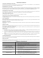
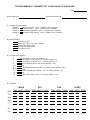
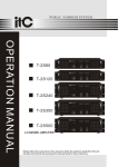
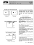
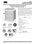
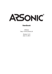
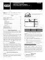
installation and
start-up instructions
TSTAT
PROGRAMMABLE THERMOSTATS
Cancels:
NOTE: Read the entire instruction manual before starting the
installation.
This symbol → indicates a change since the last issue.
II TSTAT-0-11
II TSTAT-0-19
9-98
As an ENERGY STAR Partner, Bryant Heating & Cooling
Systems has determined that this product meets the ENERGY STAR guidelines for energy efficiency.
INDEX
Page
SAFETY CONSIDERATIONS .....................................................1
INTRODUCTION ..........................................................................1
INSTALLATION CONSIDERATIONS .......................................1
INSTALLATION......................................................................1-12
Location .................................................................................1-2
Set DIP Switches ......................................................................2
Install Thermostat ..................................................................2-3
Set Thermostat Configuration ...............................................3-4
Check Thermostat Operation ................................................4-5
Final Settings ............................................................................5
Checklist....................................................................................5
WIRING DIAGRAMS .............................................................6-12
OPERATIONAL OPERATION ..................................................13
TROUBLESHOOTING ...............................................................13
CONFIGURATION RECORD....................................................14
®
A98427
HEIGHT (IN.)
4-1/4
SAFETY CONSIDERATIONS
Read and follow manufacturer instructions carefully. Follow all
local electrical codes during installation. All wiring must conform
to local and national electrical codes. Improper wiring or installation may damage thermostat.
.
Recognize safety information. This is the safety-alert symbol
When you see this symbol on the equipment and in the instruction
manual, be alert to the potential for personal injury.
Understand the signal words DANGER, WARNING, and CAUTION. These words are used with the safety-alert symbol. DANGER identifies the most serious hazards which will result in severe
personal injury or death. WARNING signifies a hazard which
could result in personal injury or death. CAUTION is used to
identify unsafe practices which would result in minor personal
injury or product and property damage.
WIDTH (IN.)
7-1/2
DEPTH (IN.)
1-3/8
→ Fig. 1—Bryant Programmable Thermostat
MODELS
There are 3 different models. The 9th and 10th letters of the part
number indicate the model. These 2 letters appear on the package
and on the circuit board. Be sure to have the proper thermostat for
the intended application. Models are:
AC - 1-stage cool, 1-stage heat - for AC systems only.
HP - 1-stage cool, 2-stage heat - for either HP or AC with 2-stage
heat.
2S - 2-stage cool, 2-stage heat - for 2-speed AC systems, or
2-stage cool, 3-stage heat - for 2-speed HP systems, or
1-stage cool, 4-stage heat - for 1-speed HP with special
3-stage electric heat.
Use each only for its intended purpose. (See Table 1.)
INTRODUCTION
Bryant’s 7-day programmable thermostats are wall-mounted, lowvoltage thermostats which maintain room temperature by controlling the operation of a heating and air conditioning system.
Separate heating and cooling setpoints, plus auto changeover allow
setback programming for maximum energy savings. All of the
thermostats allow up to 4 time/temperature settings to be programmed per 24 hr period and store programs for 7 independent
days. Batteries are not required; during a power interruption, the
internal memory stores programs for an unlimited time and the
clock continues to run for at least 72 hrs.
→ OUTDOOR TEMPERATURE SENSING
All Bryant programmable thermostats may be equipped with an
optional
outdoor
temperature
sensor,
Part
No.
TSTATXXSEN01-B. If it is to be used, plan installation so that 2
wires can be run from the thermostat to an outdoor location,
preferably on the north side of the house OR refer to Installation
Instructions included with the outdoor temperature sensor for
simplified connection. Sensor can be mounted to outdoor unit and
existing control wires used for its connection. Details are provided
to the sensor instructions.
INSTALLATION CONSIDERATIONS
POWER
Note that all TSTAT models require no batteries and are not
"power stealing". They do require 24VAC (R and C terminals) to
be connected for proper operation. Thermostat will not operate
without these 2 connections.
INSTALLATION
I. THERMOSTAT LOCATION
Thermostat should be mounted:
• Approximately 5 ft (1.5m) from floor.
—1—
•
Close to or in a frequently used room, preferably on an inside
partitioning wall.
•
On a section of wall without pipes or duct work.
→ SWITCH D - INTELLIGENT HEAT STAGING SELECT
(ACTIVE ON 2S MODELS ONLY)
This switch converts a 2-speed heat pump thermostat with 1 stage
of auxiliary heat into a 1-speed heat pump thermostat with 3 stages
of auxiliary heat for comfortable leaving air temperature. It
requires selected heaters with 2:1 ratio element sizes plus FK, FV
fan coil. Refer to variable-speed fan coil literature for details.
TO SET:
OFF—for normal 2-speed operation. This is factory default.
ON—for intelligent 3-stage heat with FK, FV fan coil.
Thermostat should NOT be mounted:
•
Close to a window, on an outside wall, or next to a door leading
to the outside.
• Exposed to direct light and heat from a lamp, sun, fireplace, or
other temperature-radiating object which may cause a false
reading.
• Close to or in direct airflow from supply registers and return-air
grilles.
• In areas with poor air circulation, such as behind a door or in
an alcove.
→ II.
III.
INSTALL THERMOSTAT
WARNING: Before installing thermostat, turn off all
power to unit. There may be more than 1 power disconnect. Electrical shock can cause personal injury or death.
SET DIP SWITCHES
There is a 4 section DIP switch within the thermostat which must
be properly set by the installer. It is easiest to set these 4 switches
before the thermostat is mounted to the wall, so STOP and
complete the following steps:
1. Turn OFF all power to unit.
2. If an existing thermostat is being replaced:
a. Remove existing thermostat from wall.
1. Open hinged thermostat cover.
b. Disconnect wires from existing thermostat, 1 at a time.
Be careful not to allow wires to fall back into the wall.
2. Remove cover completely by snapping it apart at hinge.
3. Open thermostat by pressing back half of the right end of
plastic case inward while, at the same time, pulling front
and back halves apart at the right end. The 2 halves will
swing apart.
c. As each wire is disconnected, record wire color and
terminal marking.
d. Discard or recycle old thermostat.
4. Snap hinge apart to completely separate the 2 halves.
NOTE: Mercury is a hazardous waste and MUST be disposed of
properly.
5. Switches are located in upper right corner of circuit board.
To change switch position, use corner of a small screwdriver to slide switch to opposite position.
3. Open thermostat rear door (mounting base) to expose
mounting holes. The base can be removed to simplify
mounting. Snap apart carefully at hinge to separate mounting base from remainder of thermostat.
6. After switches have been set, do not reassemble the 2
halves. The rear plastic will be first mounted to wall.
SWITCH A - ZONING SELECT (ACTIVE ON ALL MODELS)
This switch selects or defeats the 4 cycles per hour limit and a
5-minute compressor timeguard. These timers MUST be enabled
for normal operation and disabled for zoning applications. (In
zoning applications the zone control center performs these timing
functions.)
TO SET:
OFF— for normal operation. This is the factory default.
ON—for zoned installations ONLY.
4. Route thermostat wires through large hole in mounting
base. Level mounting base against wall (for aesthetic value
only—thermostat need not be leveled for proper operation)
and mark wall through 2 mounting holes.
SWITCH B - SETBACK RECOVERY (ACTIVE ON ALL
MODELS)
Selects between normal and smart recovery from setback. Normal
recovery changes to the new setpoint at the programmed time.
Smart recovery, which is active in heating mode only, starts earlier
and adjusts the setpoint slowly so that room temperature will arrive
at the programmed temperature at the programmed time.
TO SET:
OFF—for smart recovery. This is the factory default.
ON—for normal recovery.
7. Adjust length and routing of each wire to reach proper
terminal and connector block on mounting base with 1/4 in.
of extra wire. Strip only 1/4 in. of insulation from each wire
to prevent adjacent wires from shorting together when
connected.
SWITCH C - HP/AC SELECT (ACTIVE ON HP AND 2S
MODELS ONLY)
Use to select between AC and HP installations. HP and 2S models
have an extra relay to control the HP reversing valve. When a HP
thermostat is placed in the AC mode, this extra relay is converted
to a second stage heat output. This allows thermostat control of
2-stage furnaces or 2-stage strip heat with AC systems. (AC mode
also uses W rather than Y for first-stage heat.)
TO SET:
OFF—for HP applications. Extra relay controls reversing valve.
This is factory default.
ON—for AC applications. Extra output can be used for 2-stage
heat.
CAUTION: Improper wiring or installation may damage
the thermostat. Check to make sure wiring is correct
before proceeding with installation or turning on unit.
5. Drill two 3/16-in. mounting holes in wall where marked.
6. Secure mounting base to wall with 2 screws and anchors
provided, (additional anchoring holes available for more
secure mounting if needed) making sure all wires extend
through hole in mounting base.
8. Match and connect equipment wires to proper terminals of
the connector blocks. (See Table 1, and Fig. 2 through 24.)
Both R and C must be connected for proper thermostat
operation.
9. Push any excess wire into wall and against mounting base.
Seal hole in wall to prevent air leaks. Leaks can affect
operation.
10. Snap hinge back together.
11. Close thermostat assembly making sure pins on back of
circuit board align with sockets in connector.
12. Turn ON power to unit.
—2—
→ TABLE 1—MODEL SELECTION AND WIRING DIAGRAM CHART
INDOOR
UNIT
1-Stage
Furnace
2-Stage
Furnace
Typical Fan Coil
Variable-Speed
(FK, FV) Fan Coil
AIR CONDITIONER
1 Speed
Model AC
See Fig. 2
Model AC
Model HP
See Fig. 3
See Fig. 4
Model AC
Model HP
See Fig. 5
See Fig. 6
Model AC
Model HP
See Fig. 15
See Fig. 16
→ On power up, all display segments will light for 5 sec. For the next
2 Speed
Model 2S
See Fig. 8
Model 2S
See Fig. 9
Model 2S
See Fig. 10
Model 2S
See Fig. 17
D.
5 sec, a 2-digit code appears on large display which identifies
thermostat configuration:
HEAT PUMP
1 Speed
Requires Dual Fuel
Thermostat
Requires Dual Fuel
Thermostat
Model HP
See Fig. 7
Model 2S
See Fig. 14
2 Speed
Model 2S
See Fig. 11
Model 2S
See Fig. 12
Model 2S
See Fig. 13
Model 2S
See Fig. 18
Configuration Options — Selection:
OPTION 1—ANTICIPATOR ADJUSTMENT
This adjustment controls sensitivity and cycle rate of thermostat.
Higher numbers decrease sensitivity and slow cycle rate. Lower
numbers increase sensitivity and cycle rate. However, a limiting
feature will not allow more than 4 cycles per hr, regardless of
setting. Anticipator values can range from 1 to 9. Factory default
is 3. This default setting will provide optimum performance in
nearly all installations. Try it first. Do not change setting unless
there is evidence of the need to do so.
Unlike conventional anticipators, this setting is not determined by
current draw. There is no need to measure, know, or compensate
for current draw. There is also no droop with this thermostat.
Regardless of setting and number of stages, both heating and
cooling will control to their respective set points.
TO ADJUST:
1. AC—for 1-speed air conditioner
2. HP—for 1-speed heat pump
3. A2—for 2-speed air conditioner
4. H2—for 2-speed heat pump
5. HS—for intelligent heat staging with FK, FV Fan Coil and
1-speed heat pump
When this identifier disappears, normal operation begins. The
MODE control should be set to OFF and FAN control to AUTO,
so equipment does not start until further configuration and checkout is completed.
→ IV.
SET THERMOSTAT CONFIGURATION
Configuration options, like DIP switch settings, are intended to be
selected at installation and normally are not modified by the
homeowner. These options are not discussed in the Homeowner’s
Manual and therefore must be made as part of the installation. A
special procedure allows entry into the configuration mode. While
in configuration mode, 7 selections can be made. A description of
each of these and how to use the configuration mode follows.
1. Enter configuration mode if not already there. See above.
The upper small (COOL set point) display will be flashing
01. If not, use up and down buttons to move it to 01.
2. Press SET TIME/TEMP button once to flash current
selection of 1, 2, 3, 4, 5, 6, 7, 8, or 9 on large display.
Factory default is 3.
A. Configuration Options — Summary:
Option 01—Anticipator adjustment
Option 02—Clean filter timer adjustment
Option 03—Fahrenheit or Celsius operation
Option 04—Enable fan (G) ON with any heat (W)
Option 05—07—Not applicable
Option 08—Auxiliary heat lockout temperature adjustment
Option 09—12—Not applicable
Option 13—Room temperature offset adjustment
Option 14—Not applicable
Option 15—Enable AUTO mode
3. Use up and down buttons to move between available
choices.
4. Press SET TIME/TEMP button again to flash upper small
display for selection of another option, or press END to exit
configuration mode.
OPTION 2—CLEAN FILTER TIMER
Select hours of blower operation (heating, cooling, or fan) before
CLEAN FILTER icon is displayed. With OFF selected, icon will
never come on, disabling this feature. Time selection can range
from 400 to 3600 hr by selecting numbers 1 through 9. (Time is
400 X number selected.) Factory default is 2 (800 hr). Recommended selections are: disposable filter—400 to 800 hr, media
filter—1200 to 1600 hr, or electronic air cleaner—1600 to 2400 hr
of blower operation.
TO SELECT OR ADJUST:
1. Enter configuration mode if not already there. See above.
Use up and down buttons to make small (now flashing)
display indicate 02.
2. Press SET TIME/TEMP button once to flash the current
selection of OF, 1, 2, 3, 4, 5, 6, 7, 8, or 9 on large display.
Factory default is 2.
3. Use up and down buttons to move between available
choices.
4. Press SET TIME/TEMP button again to flash upper small
display for selection of another option, or press END to exit
configuration mode.
OPTION 3—FAHRENHEIT OR CELSIUS OPERATION
Select between Fahrenheit and Celsius operation. Factory default
is Fahrenheit.
TO SELECT OR ADJUST:
B. To Enter Configuration Mode:
Press and hold FAN button for approximately 10 sec until COOL
set point display indicates a flashing 01. The thermostat is now in
configuration mode. It will automatically exit this mode if no
button is pressed for 3 minutes. Pressing END button will exit
configuration mode immediately.
C. While in Configuration Mode:
The upper small (COOL set point) display indicates selected
option number and large display indicates selection made within
that option. One of these will be flashing. The up and down buttons
are used both to move between available options and to make
selection for each option. When option number (small display) is
flashing, up and down buttons adjust it, moving between available
option numbers. After desired option number has been selected,
press SET TIME/TEMP button once. The large display will now
flash, indicating that up and down buttons now control available
choices within that option. Each press of SET TIME/TEMP button
switches between available option (small display) and available
selections within each option (large display).
—3—
1. Enter configuration mode if not already there. See above.
Use up and down buttons to make small (now flashing)
display indicate 03.
2. Press SET TIME/TEMP button once to flash current
selection of F or C. Factory default is F.
3. Use up and down buttons to move between F and C on large
display.
4. Press SET TIME/TEMP button again to flash upper small
display for selection of another option, or press END to exit
configuration mode.
TO SELECT:
1. Enter configuration mode if not already there. See above.
Use up and down buttons to make small (now flashing)
display indicate 13.
2. Press SET TIME/TEMP button once to flash large display.
3. Use up or down buttons to move between -5, -4, -3, -2, -1,
0, 1, 2, 3, 4, or 5 on large display. Factory default is 0.
4. Press SET TIME/TEMP button again to flash upper small
display for selection of another option, or press END to exit
configuration mode.
OPTION 4—ENABLE FAN (G) ON WITH ANY HEAT (W)
This selection determines whether the G (fan) output is to be on or
off when any W (furnace or strip heat) output is ON. Most fan coils
manage their own blowers and do not require a separate G signal.
For these applications, select OF (off). Some auxiliary heaters
require a separate G signal to turn on the blower. In this case,
select ON. Factory default is OF.
TO SELECT:
1. Enter configuration mode if not already there. See above.
Use up and down buttons to make small (now flashing)
display indicate 04.
2. Press SET TIME/TEMP button once to flash the currect
selection of OF or ON. Factory default is OF.
3. Use up and down buttons to move between OF and ON on
large display.
4. Press SET TIME/TEMP button again to flash upper small
display for selection of another option, or press END to exit
configuration mode.
OPTION 8—AUXILIARY HEAT LOCKOUT TEMPERATURE
Present in heat pump and 2-speed models only when configured as
a heat pump. Outdoor temperature sensor must be attached. This
option allows selection of an outdoor temperature of 5 through
55°F in 5° steps (or equivalent values in C), or OF (off). Auxiliary
heat is prevented from operating for outdoor temperatures above
the selected temperature. If OF (off) is selected, auxiliary heat is
allowed at all outdoor temperatures. If selected, emergency heat
(EHEAT) overrides this feature. Factory default is OF.
TO SELECT:
1. Enter configuration mode if not already there. See above.
Use up and down buttons to make small (now flashing)
display indicate 08.
2. Press SET TIME/TEMP button once to flash large display.
3. Use up or down buttons to move between OF, 5, 10, 15, 20,
25, 30, 35, 40, 45, 50, or 55 on large display. Factory
default is OF.
4. Press SET TIME/TEMP button again to flash upper small
display for selection of another option, or press END to exit
configuration mode.
OPTION 13—ROOM TEMPERATURE OFFSET ADJUST
This option allows calibration (or deliberate miscalibration) of
room temperature sensor. There are various reasons why homeowners may want to have displayed temperature adjusted to a
higher or lower value. The selected number is number of degrees,
plus or minus, which will be added to actual temperature. The
numbers can range between -5 and +5. Factory default is 0. This
adjusted value will be used as actual temperature for both display
and control action. For example, if 2 is selected, 72°F actual will
read 74°F. If set point is 72°F, the room will control to an actual
temperature of 70°F which will be displayed and acted upon as if
it were 72°F. The effect is that a positive number selection will
make the room temperature lower and vice versa. The thermostat
is calibrated within an accuracy of plus or minus 1° when shipped
from the factory, so this adjustment will provide the best accuracy
when set to 0.
OPTION 15—ENABLE AUTO MODE
This option allows the installer to enable or disable AUTO mode
(automatic changeover between heat and cool). When disabled,
AUTO icon does not appear when successive presses of MODE
button are used to move between OFF, HEAT, COOL, and
EHEAT (in heat pump systems). Factory default is ON (AUTO
enabled).
TO SELECT:
1. Enter configuration mode if not already there. See above.
Use up and down buttons to make small (now flashing)
display indicate 15.
2. Press SET TIME/TEMP button once to flash large display.
3. Use up and down buttons to move between OF and ON on
large display. Factory default is ON (AUTO enabled).
4. Press SET TIME/TEMP button again to flash upper small
display for selection of another option, or press END to exit
configuration mode.
→ V.
CHECK THERMOSTAT OPERATION
Before doing the checkout, press HOLD button to turn on HOLD
icon, locking thermostat in hold mode. This will assure set points
don’t change during the checkout. Outputs for each stage of
operation are listed in Table 2. In the table, the actual use of each
terminal is underlined for terminals having double use.
TO TEST THE FAN:
1. Press FAN button. The fan ON icon and the G output will
go on within a few seconds, causing fan to operate.
2. Pressing FAN button again will turn off the G output and
turn off fan AUTO icon.
TO TEST COOLING:
Press MODE button until COOL icon under it turns on. Press
down button until cool set point (upper right 2 digit display with
COOL now flashing under it) is 2° or 3° below room temperature.
This will create a cooling demand. A small triangle to the left of
this COOL icon will flash or come on continually. Flashing means
the equipment is going to turn on but is presently being held off by
a system timer. (See Operational Information for timer descriptions.) Defeat the timer by pressing INCREASE TEMPERATURE
button (up and FAN buttons together). This will make the triangle
stay on and turn Cool Stage 1 on. For actual outputs, refer to Table
2, making sure the correct row from the table is selected. To turn
off, raise cooling set point above the room temperature. Cool Stage
1 and the triangle will turn off within a few seconds.
If system has 2 cooling stages, it will start on Cool Stage 1 and
proceed to Cool Stage 2, 15 minutes later due to a staging timer
which requires 15 minutes between successive stages. The INCREASE TEMPERATURE button (up and FAN buttons) cannot
be used to defeat this timer. This timer can be defeated by reducing
the set point to more than 5° below room temperature, bringing on
a Cool Stage 2 demand within 5 seconds. Remember: 2 stage
cooling units often have a 1 minute off time between lo and high,
so the thermostat’s demand will not show immediately as a change
in the outdoor unit. It will show immediately as an increase in the
indoor fan speed.
—4—
→ VI.
TO TEST HEATING:
Press MODE button until HEAT icon under it turns on. Press up
button until HEAT set point (LOWER right 2 digit display with
HEAT now flashing under it) is 2° or 3° (not more) above room
temperature. This will create a Heat Stage 1 demand. A small
triangle to the left of this HEAT icon will flash or come on
continually. Flashing means the equipment is going to turn on but
is presently being held off by a system timer. (See Operational
Information for timer descriptions.) Defeat timer by pressing
INCREASE TEMPERATURE button (up and FAN buttons together). This will make the triangle stay on and turn on Heat Stage
1. To turn off, reduce heating set point below room temperature.
The heating and the triangle will turn off within a few seconds.
If the system has multiple heat stages, it will start on Heat Stage 1
and proceed to Heat Stage 2, 15 minutes later due to a staging
timer which requires 15 minutes between successive stages. The
INCREASE TEMPERATURE button (up and FAN buttons)
cannot be used to defeat this timer. If set point is raised more than
5° above room temperature, the staging timer is defeated and the
thermostat will call for higher stages within 5 sec. Use this method
if there are only 2 stages of heat. If more than 2 stages of heat are
available, do not use this method because once the demand
exceeds 5°, the thermostat may jump to the highest stage. With
more than 2 stages available, let the timer advance one stage every
15 minutes.
TO TEST EMERGENCY HEAT (heat pump systems only):
To test, press MODE button until EHEAT icon turns on. This will
allow operation of auxiliary heat only. Raising set point above
room temperature will turn on the first stage of auxiliary heating
(W/W1). Raising set point more than 5° above room temperature
will advance to full heat, if it is available (O/W2 or Y1/W2 will
come on—see Table 2). Reducing set point below room temperature will turn all heat off.
FINAL SETTINGS
1. Assuming the system is to be left in operation after the
installation is complete, use MODE button to select between HEAT, COOL, EHEAT, or AUTO to provide the
desired operation of heating, cooling, or both.
2. The default set points and programmed schedule conform to
the Energy Star requirements of the U.S. Department of
Energy for both heating and cooling. These provide energy
saving temperature settings.
3. Turn on HOLD if fixed set points are to be used. If the
programmed schedule is to be used, make sure the HOLD
icon is off.
4. For further information on temperature selection and programming, refer to Homeowner’s Manual.
5. If AUTO mode is to be used, be sure both heat and cool set
points are properly adjusted.
6. The FAN button may be used to select between AUTO (fan
on only with equipment) and FAN (fan on continuously) fan
modes.
→ VII.
CHECKLIST
1. Put away tools and instruments, and clean up debris.
2. Review Homeowner’s Guide with owner.
3. Leave literature packet with owner.
4. Fill out and return survey card.
—5—
—6—
2-Speed HP
*1-Speed HP
2S01-B
2S01-B
OFF
OFF
ON
OFF
ON
EITHER
R
R
R
C
C
C
G
G
G
Y1/W2
Y/Y2
W/W1
†Y1/W2 is on without W/W1
AC = Air conditioner, HP = Heat pump, 2S = 2-speed, N/A = Not applicable, * = Intelligent Heat option
Model Numbers: TSTAT--PAC01-B, TSTAT-PHP01-B, TSTAT--P2S01-B
2-Speed AC
2S01-B
Y/Y2
W/W1
O/W2
W/W1
Y1/W2†
N/A
N/A
W/W1, Y1/W2
N/A
Y1/W2
Y/Y2
Y1/W2
Y/Y2
N/A
Y/Y2
O/W2
O/W2
N/A
THERMOSTAT OUTPUT
AC/HP
Staging
Cool
Heat
Heat
24v
Reversing Valve
Heat Stage 3 Heat Stage 4 Cool Stage 1
Common Fan
TSTAT Model Outdoor Unit Configuration Configuration
Stage 2
Stage 1 Stage 2
Hot
(Switch C)
(Switch D)
AC01-B
AC
EITHER
EITHER
R
C
G
W/W1
N/A
N/A
N/A
Y/Y2
N/A
N/A
HP01-B
HP
OFF
EITHER
R
C
G
Y/Y2
W/W1
N/A
N/A
Y/Y2
N/A
O/W2
W/W1
HP01-B
AC
ON
EITHER
R
C
G
O/W2
N/A
N/A
Y/Y2
N/A
N/A
→ TABLE 2—PROGRAMMABLE THERMOSTAT QUICK REFERENCE
MODEL AC
THERMOSTAT
SINGLE-STAGE
FURNACE
24 VAC HOT
R
R
FAN
G
G
SINGLE-SPEED
AIR CONDITIONER
HEAT STAGE 1 W/W1
W
COOL STAGE 1 Y/Y2
Y
Y
C
C
N/A
O/W2
N/A
Y1/W2
24 VAC COMM
C
N/A
B
OUTDOOR
S1
SENSOR
CONNECTION
S2
See note 1
ON
SUGGESTED DIP
SWITCH SETTINGS
A
B
C
D
OFF OFF OFF OFF
A98485
→ Fig. 2—Single-Speed Air Conditioner with SingleStage Furnace—Model AC Thermostat
MODEL AC
THERMOSTAT
TWO-STAGE OR
VARIABLE-SPEED
FURNACE
24 VAC HOT
R
R
FAN
G
G
HEAT STAGE 1 W/W1
W/W1
COOL STAGE 1 Y/Y2
Y/Y2
N/A
O/W2
N/A
Y1/W2
TWO-STAGE OR
VARIABLE-SPEED
FURNACE
MODEL HP
THERMOSTAT
SINGLE-SPEED
AIR CONDITIONER
Y
W2
24 VAC HOT
R
R
FAN
G
G
HEAT STAGE 1 W/W1
W/W1
COOL STAGE 1 Y/Y2
Y/Y2
HEAT STAGE 2 O/W2
W2
HUM
24 VAC COMM
C
B
N/A
B
S1
OUTDOOR
S1
C
N/A
OUTDOOR
C
Y
Y1/W2
N/A
HUM
24 VAC COMM
SINGLE-SPEED
AIR CONDITIONER
C
C
C
SENSOR
SENSOR
CONNECTION
See notes 1 and 6
S2
CONNECTION
ON
See note 2
S2
ON
SUGGESTED DIP
SWITCH SETTINGS
A
B
C
SUGGESTED DIP
SWITCH SETTINGS
D
A
OFF OFF OFF OFF
B
OFF OFF
C
D
ON OFF
A98486
→ Fig. 3—Single-Speed Air Conditioner
with 2-Stage or Variable-Speed Furnace
—Model AC Thermostat
A98487
→ Fig. 4—Single-Speed Air Conditioner
with 2-Stage or Variable-Speed Furnace
—Model HP Thermostat
—7—
MODEL HP
THERMOSTAT
MODEL AC
THERMOSTAT
TYPICAL
FAN COIL
TYPICAL
FAN COIL
24 VAC HOT
R
R
FAN
G
G
SINGLE-SPEED
AIR CONDITIONER
24 VAC HOT
R
R
HEAT STAGE 1
W/W1
W2
FAN
G
G
COOL STAGE 1
Y/Y2
Y
HEAT STAGE 2
O/W2
W3
N/A
Y1/W2
E
24 VAC COMM
C
C
N/A
B
OUTDOOR
S1
COOL STAGE 1 Y/Y2
Y *
HEAT STAGE 1 W/W1
W2
N/A
O/W2
W3
N/A
Y1/W2
E
24 VAC COMM
C
N/A
B
Y
*
Y
C
C
C
SENSOR
OUTDOOR
SINGLE-SPEED
AIR CONDITIONER
S1
See notes 2, 7, and 8
CONNECTION
S2
SENSOR
CONNECTION
See notes 1, 7, and 8
S2
ON
SUGGESTED DIP
SWITCH SETTINGS
ON
SUGGESTED DIP
SWITCH SETTINGS
A
B
C
A
D
A98488
→ Fig. 5—Single-Speed Air Conditioner
with Typical Fan Coil—Model AC Thermostat
(Single-Stage Heat Control)
TYPICAL
FAN COIL
C
D
ON OFF
A98489
→ Fig. 6—Single-Speed Air Conditioner
with Typical Fan Coil
—Model HP Thermostat
(Dual-Stage Heat Control)
OFF OFF OFF OFF
MODEL HP
THERMOSTAT
B
OFF OFF
MODEL 2S
THERMOSTAT
SINGLE-SPEED
HEAT PUMP
SINGLE-STAGE
FURNACE
TWO-SPEED
AIR CONDITIONER
COOL STAGE 1 Y1/W2
24 VAC HOT
R
R
FAN
G
G
FAN
RVS COOLING O/W2
COOL/HEAT
STAGE 1
Y/Y2
G
G
HEAT STAGE 1 W/W1
W
COOL STAGE 2 Y/Y2
Y
Y2
O
Y
HEAT STAGE 2 W/W1
W2
Y1/W2
W3
N/A
Y1
R
*
Y
W2
N/A
O/W2
24 VAC HOT
R
R
R
24 VAC COMM
C
C
C
N/A
B
OUTDOOR
S1
E
24 VAC COMM
C
N/A
B
OUTDOOR
S1
C
C
SENSOR
SENSOR
CONNECTION
CONNECTION
See notes 3, 7, and 8
S2
S2
See note 2
ON
ON
SUGGESTED DIP
SWITCH SETTINGS
SUGGESTED DIP
SWITCH SETTINGS
A
B
C
A
D
B
OFF OFF
OFF OFF OFF OFF
A98490
→ Fig. 7—Single-Speed Heat Pump
with Typical Fan Coil—Model HP Thermostat
—8—
C
D
ON OFF
→ Fig. 8—Two-Speed Air Conditioner
with Single-Stage Furnace
—Model 2S Thermostat
A98491
MODEL 2S
THERMOSTAT
TWO-STAGE OR
VARIABLE-SPEED
FURNACE
MODEL 2S
THERMOSTAT
TWO-SPEED
AIR CONDITIONER
24 VAC HOT
R
R
FAN
G
G
Y1
G
R
G
HEAT STAGE 1 W/W1
W/W1
COOL STAGE 2 Y/Y2
Y/Y2
HEAT STAGE 2 O/W2
W2
HEAT STAGE 1 W/W1
W2
COOL STAGE 2 Y/Y2
Y
HEAT STAGE 2 O/W2
W3
COOL STAGE 1 Y1/W2
E
*
Y2
Y2
24 VAC HOT
R
R
R
24 VAC COMM
C
C
C
N/A
B
HUM
OUTDOOR
S1
Y1
24 VAC COMM
C
N/A
B
OUTDOOR
S1
C
C
SENSOR
SENSOR
CONNECTION
TWO-SPEED
AIR CONDITIONER
Y1 *
COOL STAGE 1 Y1/W2
FAN
TYPICAL
FAN COIL
CONNECTION
S2
S2
See notes 2, 7, and 8
See notes 2, 5, and 7
ON
ON
SUGGESTED DIP
SWITCH SETTINGS
SUGGESTED DIP
SWITCH SETTINGS
A
B
C
A
D
A98492
D
→ Fig. 10—Two-Speed Air Conditioner
with Typical Fan Coil—Model 2S Thermostat
→ Fig. 9—Two-Speed Air Conditioner
with 2-Stage or Variable-Speed Furnace
—Model 2S Thermostat
COOL/HEAT
STAGE 1
C
A98493
OFF OFF ON OFF
MODEL 2S
THERMOSTAT
B
OFF OFF ON OFF
SINGLE-STAGE
FURNACE
MODEL 2S
THERMOSTAT
TWO-SPEED
HEAT PUMP
Y1/W2
Y1
RVS COOLING O/W2
O
HEAT STAGE 3 W/W1
W
W2
COOL/HEAT
STAGE 2
Y/Y2
Y
Y2
FAN
G
G
W3
24 VAC HOT
R
R
R
TWO-STAGE OR
VARIABLE-SPEED
FURNACE
TWO-SPEED
HEAT PUMP
Y1/W2
Y1 *
Y1
RVS COOLING O/W2
O *
O
HEAT STAGE 3 W/W1
W/W1
W2
COOL/HEAT
STAGE 1
COOL/HEAT
STAGE 2
Y/Y2
Y/Y2
Y2
FAN
G
G
W3
24 VAC HOT
R
R
R
W2
24 VAC COMM
C
C
B
N/A
B
HUM
S1
OUTDOOR
S1
24 VAC COMM
C
N/A
OUTDOOR
C
C
C
SENSOR
SENSOR
CONNECTION
CONNECTION
S2
S2
See notes 3, 9, and 11
See notes 3, 6, 7, 9, and 11
ON
ON
SUGGESTED DIP
SWITCH SETTINGS
SUGGESTED DIP
SWITCH SETTINGS
A
B
C
A
D
OFF OFF OFF OFF
A98494
→ Fig. 11—Two-Speed Heat Pump
with Single-Stage Furnace
—Model 2S Thermostat
B
C
D
OFF OFF OFF OFF
→ Fig. 12—Two-Speed Heat Pump
with 2-Stage or Variable-Speed Furnace
—Model 2S Thermostat
—9—
A98495
MODEL 2S
THERMOSTAT
DH
MODEL 2S
THERMOSTAT
TYPICAL
FAN COIL
24 VAC HOT
R
R
FAN
G
G
W2
W3
Y/Y2
RVS COOLING O/W2
R
FAN
G
G
COOL/HEAT
STAGE 1
Y/Y2
Y/Y2
HEAT STAGE 2 W/W1
W1
HEAT STAGE 3 Y1/W2
W2
RVS COOLING O/W2
O
J1
JUMPER
R
Y
REMOVE
J2 JUMPER
FOR HEAT
STAGING
W2
O
O
Y *
Y1/W2
R
Y2
E
COOL/HEAT
STAGE 1
24 VAC HOT
R
W2
HEAT STAGE 3 W/W1
COOL/HEAT
STAGE 2
TWO-SPEED
HEAT PUMP
SINGLE-SPEED
HEAT PUMP
EASY SELECT
TERMINAL BOARD
Y1
Y1
24 VAC COMM
C
N/A
B
OUTDOOR
S1
C
C
W3
24 VAC COMM
C
C
C
N/A
B
See notes 3, 4, and 8
SENSOR
OUTDOOR
S1
CONNECTION
S2
CONNECTION
SENSOR
S2
ON
See notes 3, 7, 8, 9, and 11
SUGGESTED DIP
SWITCH SETTINGS
ON
A
SUGGESTED DIP
SWITCH SETTINGS
A
B
C
D
OFF OFF OFF OFF
A98496
→ Fig. 13—Two-Speed Heat Pump
with Typical Fan Coil—Model 2S Thermostat
MODEL AC
THERMOSTAT
EASY SELECT
TERMINAL BOARD
DH
R
24 VAC HOT
HEAT STAGE 1 W/W1
C
D
A98497
→ Fig. 14—Single-Speed Heat Pump
with Variable-Speed Fan Coil (FK, FV) and Special 3-Stage
Electric Heat
—Model 2S Thermostat
MODEL HP
THERMOSTAT
SINGLE-SPEED
AIR CONDITIONER
EASY SELECT
TERMINAL BOARD
DH
J1 JUMPER
R
W1
B
OFF OFF OFF ON
24 VAC HOT
R
R
FAN
G
G
J2 JUMPER
N/A
O/W2
W2
HEAT STAGE 1 W/W1
W1
FAN
G
G
HEAT STAGE 2 O/W2
W2
N/A
Y1/W2
Y1
COOL STAGE 1 Y/Y2
Y/Y2
COOL STAGE 1 Y/Y2
Y/Y2
Y1/W2
N/A
Y
O
24 VAC COMM
C
N/A
B
OUTDOOR
S1
C
CONNECTION
J1
JUMPER
REMOVE
J2 JUMPER
FOR HEAT
STAGING
Y
Y1
O
C
See notes 1 and 8
SENSOR
SINGLE-SPEED
AIR CONDITIONER
24 VAC COMM
C
N/A
B
OUTDOOR
S1
C
See notes 2 and 8
SENSOR
CONNECTION
S2
C
S2
ON
ON
SUGGESTED DIP
SWITCH SETTINGS
SUGGESTED DIP
SWITCH SETTINGS
A
B
C
A
D
B
C
D
OFF OFF ON OFF
OFF OFF OFF OFF
A98498
→ Fig. 15—Single-Speed Air Conditioner
with Variable-Speed Fan Coil (FK, FV)
—Model AC Thermostat
A98499
→ Fig. 16—Single-Speed Air Conditioner
with Variable-Speed Fan Coil (FK, FV)
—Model HP Thermostat
—10—
MODEL 2S
THERMOSTAT
MODEL 2S
THERMOSTAT
EASY SELECT
TERMINAL BOARD
TWO-SPEED
HEAT PUMP
EASY SELECT
TERMINAL BLOCK
TWO-SPEED
AIR CONDITIONER
DH
J1 JUMPER
DH
24 VAC HOT
R
R
FAN
G
G
Y1
COOL STAGE 2 Y/Y2
Y/Y2
Y2
HEAT STAGE 1 W/W1
W1
HEAT STAGE 2 O/W2
W2
B
FAN
G
G
REMOVE
J2 JUMPER
FOR HEAT
STAGING
C
R
COOL/HEAT Y1/W2
STAGE 1
Y1
Y1
RVS COOLING O/W2
O
O
Y/Y2
Y2
COOL/HEAT
STAGE 2
Y/Y2
HEAT STAGE 3 W/W1
W1
W2
J2 JUMPER
O
N/A
R
R
Y1
C
R
J1
JUMPER
COOL STAGE 1 Y1/W2
24 VAC COMM
24 VAC HOT
24 VAC COMM
C
N/A
B
OUTDOOR
S1
C
W2
W3
C
C
See notes 3, 8, 9, and 11
SENSOR
OUTDOOR
S1
CONNECTION
SENSOR
S2
See notes 2 and 8
CONNECTION
S2
ON
SUGGESTED DIP
SWITCH SETTINGS
ON
A
SUGGESTED DIP
SWITCH SETTINGS
A
B
C
D
OFF OFF ON OFF
A98500
R
FAN
G
D
A98501
SPLICE
BOX
MODEL AC
THERMOSTAT
SPLICE
BOX
MODEL AC
THERMOSTAT
C
→ Fig. 18—Two-Speed Heat Pump
with Variable-Speed Fan Coil (FK, FV)
—Model 2S Thermostat
→ Fig. 17—Two-Speed Air Conditioner
with Variable-Speed Fan Coil (FK, FV)
—Model 2S Thermostat
24 VAC HOT
B
OFF OFF OFF OFF
RED
N/A
Y1/W2
FAN
G
GRN
GRN
HEAT STAGE 1 W/W1
WHT
HEAT STAGE 1 W/W1
WHT
COOL STAGE 1 Y/Y2
YEL
COOL STAGE 1 Y/Y2
YEL
N/A
O/W2
N/A
Y1/W2
24 VAC COMM
C
N/A
B
OUTDOOR
N/A
O/W2
24 VAC HOT
R
RED
24 VAC COMM
C
BRN
N/A
B
OUTDOOR
S1
BRN
SENSOR
S1
CONNECTION
See notes 1 and 11
SENSOR
CONNECTION
HEATER
CONTROL BOX
WHT
BRN
See notes 1, 11, and 12
S2
S2
ON
SUGGESTED DIP
SWITCH SETTINGS
ON
SUGGESTED DIP
SWITCH SETTINGS
A
B
C
A
B
C
D
OFF OFF OFF OFF
D
A98502
→ Fig. 19—Single-Speed Packaged Air Conditioner
with Single-Stage Gas Furnace (588A, 589A)
—11—
A98503
→ Fig. 20—Single-Speed Packaged Air Conditioner
with Single-Stage Electric Heat
(555A, 557A, 564A)
SPLICE
BOX
MODEL HP
THERMOSTAT
COOL STAGE 1 Y/Y2
FAN
G
HEATER
CONTROL BOX
SPLICE
BOX
MODEL HP
THERMOSTAT
YEL
COOL/HEAT
STAGE 1
GRN
YEL
Y/Y2
ORN
RVS COOLING O/W2
HEAT STAGE 1 W/W1
N/A
Y1/W2
WHT
WHT
RED(TRAN)
N/A
Y1/W2
PNK
WHT
HEAT STAGE 2 W/W1
R
24 VAC COMM
C
WHT
VIO
HEAT STAGE 2 O/W2
24 VAC HOT
HEATER
CONTROL BOX
RED
RED
BRN
BRN
FAN
G
GRN
24 VAC HOT
R
RED
24 VAC COMM
C
BRN
N/A
B
OUTDOOR
S1
BRN
B
N/A
OUTDOOR
S1
SENSOR
CONNECTION
See notes 2, 10, 11, and 12
See notes 3, 11, and 12
SENSOR
S2
CONNECTION
S2
ON
ON
SUGGESTED DIP
SWITCH SETTINGS
A
B
C
SUGGESTED DIP
SWITCH SETTINGS
D
A
OFF OFF ON OFF
A98504
→ Fig. 21—Single-Speed Packaged Air Conditioner
with 2-Stage Electric Heat
(555A, 557A, 564A)
SPLICE
BOX
MODEL HP
THERMOSTAT
RVS COOLING O/W2
N/A
Y1/W2
COOL/HEAT
STAGE 1
Y/Y2
C
D
A98505
→ Fig. 22—Single-Speed Packaged Heat Pump
with Single Stage Electric Heat
(655A, 657A, 664A)
HEATER
CONTROL BOX
COOL/HEAT
STAGE 1
ORN
WHT
N/A
YEL
G
24 VAC HOT
R
RED
24 VAC COMM
C
BRN
N/A
B
OUTDOOR
S1
RED(TRAN)
RED
BRN
ORN
W/W1
WHT
GRN
FAN
G
24 VAC HOT
R
RED
24 VAC COMM
C
BRN
N/A
B
OUTDOOR
S1
PNK
SENSOR
S2
YEL
Y1/W2
HEAT STAGE 2
GRN
FAN
CONNECTION
Y/Y2
RVS COOLING O/W2
WHT
SPLICE
BOX
MODEL HP
THERMOSTAT
VIO
HEAT STAGE 2 W/W1
B
OFF OFF OFF OFF
SENSOR
See notes 3, 10, 11, and 12
CONNECTION
S2
See notes 3, 11, and 12
ON
ON
SUGGESTED DIP
SWITCH SETTINGS
SUGGESTED DIP
SWITCH SETTINGS
A
B
C
A
D
B
C
D
OFF OFF OFF OFF
OFF OFF OFF OFF
A98506
→ Fig. 23—Single-Speed Packaged Heat Pump
with 2-Stage Electric Heat (665A, 657A, 664A)
A98507
→ Fig. 24—Single-Speed Packaged Heat Pump
with Single-Stage Gas Furnace (658A)
—12—
→ WIRING DIAGRAM NOTES
1. The AC model thermostat can only control 1-stage cool and 1-stage heat. Dip Switch-C on has no controlling function and can either be
ON or OFF.
2. HP and 2S model thermostat MUST have Dip Switch-C ON when installed in air conditioner applications. If required, second-stage heat
is controlled by O/W2. Refer to indoor equipment Installation Instructions for proper setup.
3. HP and 2S model thermostat MUST have Dip Switch-C OFF when installed in heat pump applications. The reversing valve is controlled
by O/W2.
4. Intelligent Heat Staging Option: 2S model thermostat with Dip Switch-C OFF and Switch-D ON. This provides single-stage heat pump
operation Y/Y2, with three-stage auxiliary heat via W/W1 and Y1/W2. Refer to variable-speed fan coil Installation Instructions. Proper
’intelligent heat capable’ electric heater package must be used.
5. As an option, lock the furnace into low-fire operation and let O/W2 control high-fire operation. Refer to indoor equipment Installation
Instructions for proper setup.
6. Furnace must control its own second-stage heat operation via furnace control algorithm. Refer to indoor equipment Installation Instructions
for proper setup.
7. Terminals marked with * may not be present on equipment.
8. Refer to fan coil Installation Instructions for proper wiring.
9. Select the "ZONE" position on the 2-speed heat pump control board.
10. Omit red and pink wires from diagram with wiring a 564A or 664A with 2-stage heaters.
11. Refer to outdoor equipment Installation Instructions for proper setup.
12. Program thermostat to bring on G (fan) with any W (heat) selection. See section under "set thermostat configuration."
—13—
→ OPERATIONAL INFORMATION
FIVE-MINUTE COMPRESSOR TIMEGUARD
This timer prevents the compressor from starting unless it has been off for at least 5 minutes. It can be defeated for 1 cycle by simultaneously
pressing the FAN mode button and the INCREASE TEMPERATURE button.
FIFTEEN-MINUTE CYCLE TIMER
This timer prevents the start of a heating or cooling cycle until at least 15 minutes after the last start of the same cycle. Its function is to assure
that equipment is not cycled more than 4 times per hour. This timer is defeated for 1 cycle when the desired temperature is manually changed.
It can also be defeated for 1 cycle by simultaneously pressing the FAN mode button and the INCREASE TEMPERATURE button.
FIFTEEN-MINUTE STAGING TIMER
In multistage heating or cooling, this timer prevents any higher stage from turning on until the preceding stage has been on for 15 minutes. This
timer is defeated if the temperature error is greater than 5˚F (usually due to a large change in desired temperature).
THREE-MINUTE MINIMUM ON TIME
In normal operation, when a stage turns on, it will not turn off for a minimum of 3 minutes.
HEAT/COOL SET POINTS (DESIRED TEMPERATURES)
A minimum difference of 2 degrees is enforced between heating and cooling set points. This is done by allowing one setting to "push" the other,
to maintain this difference.
AUTO CHANGEOVER
When the auto changeover mode is selected, a change from heat to cool (or vice versa) will not occur until an opposite mode demand has existed
for 20 minutes. If the setpoint is changed, the 20 minute requirement is deleted.
EMERGENCY HEAT MODE
When thermostat is configured as a heat pump and emergency heat mode is selected, all Y signals are locked out and W becomes energized upon
a call for heat.
POWER ON CHECK
When AC power is first applied, all segments of the display are turned on for a few seconds. Following this, the temperature display indicates the
model/configuration via the following 2 digit code:
AC—1-speed air conditioner, HP—1-speed heat pump, A2—2-speed air conditioner, H2—2-speed heat pump, HS—1-speed heat pump with
Intelligent Heat staging (3-stage auxiliary heat).
ERROR CODES
-- — If the thermostat cannot properly read room temperature, the display will indicate "--" (2 dashes) and all outputs (except the fan if on) will
turn off. This is to prevent operation of the equipment if the thermostat has failed.
E2 — If the AC line voltage drops below a minimum (brownout) level, all outputs are turned off and the display indicates E2. This condition will
remain for 15 seconds after proper line voltage is restored. If the AC line voltage disappears completely, the display will immediately go
blank.
E3 — If thermostat cannot properly read outdoor temperature, and/or it is needed for proper operation, (i.e. Option 8 is ON with no sensor
attached), E3 will alternate with room temperature on the room temperature display and the outdoor temperature will read "--".
OUTDOOR TEMPERATURE
When an outdoor temperature sensor is attached, outdoor temperature can be read by pressing up and down buttons together. While it is displayed,
the letters "od" also appear in the heat set point display.
SMART RECOVERY
With Smart Recovery selected, the transition out of a heating setback begins 90 minutes early, gradually adjusting room temperature so that the
desired temperature will be achieved at the selected time.
→ THERMOSTAT TROUBLESHOOTING
SYMPTOM
WHAT TO CHECK
"--" on temperature display
Temperature sensor reading out of range. Check sensor for damage. If recycling power
does not clear display, thermostat should be replaced.
"E2" on temperature display
Brownout condition or too low of voltage to thermostat. Double check wiring and check for
24 VAC between R and C. E2 will clear 15 seconds after proper voltage is restored.
"E3" on temperature display
Outdoor temperature reading out of range and needed for Option 8. Check outdoor temperature sensor and its wiring.
"Clean Filter" on temperature display
After the selected number of hours of blower operation "clean filter" will display on LCD.
This is to remind the homeowner to "check" filter. Press "reset filter" button to clear display and reset timer to 0.
Cooling will not come on
Select COOL mode. Decrease cooling setpoint to 10 degrees below room temperature.
Simultaneously press FAN and INCREASE TEMPERATURE buttons to defeat timers.
Check for 24 VAC at Y/Y2 terminal. If present, thermostat is OK and problem is with
equipment or wiring. If not present, replace thermostat.
Heating will not come on
Select HEAT mode. Increase heating setpoint to 10 degrees above room temperature.
Simultaneously press FAN and INCREASE TEMPERATURE buttons to defeat timers.
Check for 24 VAC at Y/Y2 (with HP) or W/W1 (with AC) terminal. If present, thermostat is
OK and problem is with equipment or wiring. If not present, replace thermostat.
—14—
P R OGR A MMA B L E T H E RM OSTAT CONFIGURATION RECORD
Date
Owner/Operator
Thermostat Model No.
A) Hardware Configuration
Switch A
Zoning Selection. (OFF = Disable, ON = Enable)
Switch B
Smart Recovery. (OFF = Enable, ON = Disable)
Switch C
Heat Pump Operation. (OFF = Enable, ON = Disable)
Switch D
Intelligent Heat Staging. (OFF = Disable, ON = Enable)
B) Mode Settings
Hold (On or Off)
Mode (Off, Heat, Cool, Auto, Eheat)
Heating Set Point Value
Cooling Set Point Value
Fan (Auto or On)
C) Configuration Options
1
Anticipator (1-9: factory default = 3)
2
Clean Filter Timer (Off or 1-9: factory default = 2)
3
Fahrenheit or Celsius (F or C: factory default = F)
4
Fan On with W (Off or On: factory default = Off)
5-7
N/A
Auxiliary Heat Lockout (Off or 5-55°F: factory default = Off)
8
9-12
N/A
13
Room Temperature Offset (-5 to +5: factory default = 0)
14
N/A
15
Enable Auto Mode (Off or On: factory default = On)
D) Schedule
WAKE
DAY
EVE
TIME HEAT COOL TIME HEAT COOL
SLEEP
TIME HEAT COOL TIME HEAT COOL
Mon
Tue
Wed
Thu
Fri
Sat
Sun
A98508
—15—
SERVICE TRAINING
Packaged Service Training programs are an excellent way to increase your
knowledge of the equipment discussed in this manual, including:
• Unit Familiarization
• Maintenance
• Installation Overview
• Operating Sequence
A large selection of product, theory, and skills programs is available, using popular
video-based formats and materials. All include video and/or slides, plus companion
book.
Classroom Service Training plus "hands-on" the products in our labs can mean
increased confidence that really pays dividends in faster troubleshooting, fewer
callbacks. Course descriptions and schedules are in our catalog.
CALL FOR FREE CATALOG 1-800-962-9212
[ ] Packaged Service Training
[ ] Classroom Service Training
A94328
© 1998 Bryant Heating & Cooling Systems 7310 W. Morris St. Indianapolis, IN 46231
—16—
Printed in U.S.A.
iitstt19
Catalog No. 13TS-TA4