1
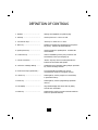
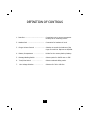
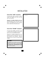
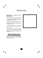
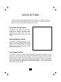
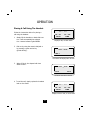
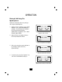
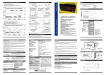
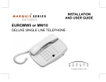
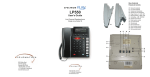
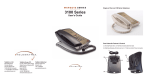
TM
USER GUIDE
MARQUIS 2802CID
2 Line Caller ID
Hotel Telephone
? Copyright TeleMatrix Inc. 2003
INTRODUCTION
Congratulations on the purchase of your TeleMatrix Marquis
2802CID Telephone. The 2802CID includes advanced features
suitable for use in hotel/motel guest room environment.
TeleMatrix has designed the 2802CID to be simple to install and
easy to use.
Advanced features include Type I Caller
Identification. The Caller ID feature requires compatibility with
the telephone PBX system. Check with your system coordinator
to verify that your PBX will deliver Caller ID information to your
guest rooms.
Your 2802CID telephone is a precision electronic device that
requires minimum maintenance. Please be sure to read the
contents set forth in the user’s guide to become familiar with the
wiring and functionality of this product.
1
COMPLIANCE AND SAFETY
As specified by FCC regulation, we are required to inform you of specific
governmental and compliance regulatory requirements, safety notices, safety
instructions and other informative information. TeleMatrix, Inc. provides this
information in a separate manual. We pack the separate Compliance and
Safety Manual within each outer box or product box when shipped.
Prior to reading this operation manual and prior to setting up your telephone,
please refer to the Compliance and Safety Manual.
If the Compliance and Safety Manual is not immediately available. Please
obtain a free copy by calling our Priority Care Department (phone number 1800-462-9446) or by downloading a copy on our Internet (web site address
www.telematrixusa.com).
CONTENTS
Features ..................................................................................
5
Controls .............…..................................................................
5
Installation ..............................................................................
10
Wall Mounting .....….................................................................
11
Battery Preparation ..................................................................
15
Switch Settings ......…...............................................................
16
Programming ..........…..............................................................
17
Operation .................….............................................................
21
Service ......................…...........................................................
32
Warranty .....................….........................................................
33
4
FEATURES
?? Two Line Operation
?? Speakerphone
?? Large, Backlit LCD Display:
? Name/Number Caller Identification Formation*
? Date/Time*
? Guest Service Directory
? Elapsed Call Timer
? Numbers Dialed
?? 10 Guest Service Keys (Speed Dial Locations)
?? TouchLite™ Message Waiting Indicator/Retrieval Feature
?? Convenient Data Port (on line 2)
?? Automatic Line Selection
?? “Soft-key” Line Selectors
?? “Soft-key” Conference Feature With Automatic Reset
?? “Soft-Key” Volume Control (Handset, Speaker– 8 step/ADA Compliant)
?? Microphone Mute Function
?? HI/Low Ringer Volume Controls
?? Line Status Indicators (In-Use/Hold/Ringing)
?? Extended Memory Back-up (Lithium Battery)
?? Desk Or Wall Mountable
?? Operates Behind 24/48 Volt Systems
?? Hearing Aid Compatible
* Caller ID/Date & Time are features require subscription to Caller ID service from
your Local Telephone Company and/or your PBX telephone system. The system
must be equipped to pass Caller ID information to the guest room.
5
CONTROLS
TOP VIEW
6
DEFINITION OF CONTROLS
1. Handset ..........…………...........…...
Hearing aid compatible, low profile styling.
2. Hold Key ................................…...
Used to place line 1 or line 2 on hold.
3. Line Selector Keys ...............……....
“Soft keys” to select line 1 or line 2.
4. Mute Key ................................…..
Disables the handset and speakerphone microphone
for privacy. Includes LED visual indicator.
5. Speakerphone Key ........................
Used to activate the speakerphone. Includes LED
visual indicator.
6. Conference Key ......................…...
Used for establishing a three-party conference call.
Automatically resets upon hanging–up.
7. Volume Control Key ......................
“Rocker” style key used to increase/decrease the
loudness of the handset and speaker.
8. TouchLite™ Message Waiting …..……
Combination visual message waiting lamp & speed-dial
key used for message retrieval.
9. Guest Service Keys (Speed Dial) ....
10 programmable speed dial keys used for
one-touch/easy-access to hotel guest services.
10. Pause Key ..............................…...
Submerged key used to program a 3 second delay
in speed dial memory.
11. Store Key .............….....................
Submerged key used for programming speed dial
memory.
12. LCD Display .................................
Large backlit display that shows caller id, dialing
and call timer information.
13. Flash Key ........………...............…..
Submerged key used to program a 600mS timed line
break in a speed dial memory.
7
CONTROLS
RIGHT SIDE
LEFT SIDE
BOTTOM
8
DEFINITION OF CONTROLS
1. Data Port .........................................…
Convenient port to connect a computer
modem, fax or answering device.
2. Handset Jack .....................................
Connection for handset coil cord.
3. Ringer Volume Controls ...................... Switches to control the loudness of the
ringer for each line. Options are HI/LOW.
4. Battery Compartment ………......…......
Holder for the memory back-up battery.
5. Message Waiting Switch ………………..
Selects option for 90VDC neon or FSK
6. Tone/Pulse Switch ………………………
Selects outbound dialing mode.
7.
Selectors for 24V or 48V line.
Line Voltage Switches ………………….
9
Caution
?? Never install telephone wiring during a lightning storm.
?? Never install telephone jacks in wet locations unless the jack is specifically
designed for wet locations.
?? Never touch uninstalled telephone wires or terminals unless the telephone line
has been disconnected at the network interface.
?? Use caution when installing or modifying telephone lines.
Parts Check List
The following parts are included with the
2802CID:
1. 15’ modular telephone line cord.
2. 3’ modular telephone line cord.
3. 10’ modular coiled handset cord.
4. Power pack.
10
INSTALLATION
Wall Mounting Your 2802CID
The TMX 2802CID was designed to be
conveniently wall mounted. There is no
additional hardware required. Follow these
easy steps:
1. The handset retaining clip must be
engaged to secure the handset when
hanging up.
To engage the clip,
unsnap the clip, rotate the clip 180º and
then snap the clip into place.
2. The bottom of the 2802CID has a
mounting wedge that must be repositioned for wall mount use.
This wedge will allow the telephone to
be at the correct angle when wall
mounted.
To install the wedge for wall mounting,
remove the two (2) screws that secure
the wall mount wedge to the base unit.
Next, press the two release tabs on the
wedge as shown. The wedge will snap
off. Rotate the wedge and snap into
place for wall mounting.
11
INSTALLATION
Connecting The Power Pack
Plugs Into Standard AC Outlet
The power pack is a fully modular device
that provides the power source to the
2802CID telephone.
To install, simply plug the power pack into a
standard 110V AC power outlet. A mounting
hole is provided to secure the power pack to
the AC outlet.
Power Input/Output Jacks
The power pack also includes two (2)
modular jacks labeled “LINE” and “PHONE”.
These jacks allow for a fully modular
installation by providing both the telephone
lines and the power source connections up
the telephone line cord. This avoids the
need for an additional power cord and
neatens the Installation.
12
INSTALLATION
Power Pack “LINE” Connection
Input Connection
The power pack “LINE” connection is used to
connect the telephone lines from the wall
jack to the telephone.
Using the 3’ modular telephone line cord
provided, connect the first end of the cord to
the RJ14 telephone jack on the wall or base
board. The remaining end of the cord plugs
into the “LINE” side of the power pack.
Power Pack “PHONE” Connection
The power pack “PHONE” connection is used
to provide both the telephone lines and the
power source to the 2802CID telephone.
Using the 15’ modular telephone line cord
provided, plug the first end of the line cord
into the back of the 2802CID. Plug the
remaining end to the power pack jack labeled
“PHONE”.
IMPORTANT!
The 2802CID will not function if the line cord
connections are not correct. If the LCD display
does not activate upon installation, make sure that
the telephone line cord connections are not
reversed (“LINE”/”PHONE”).
13
INSTALLATION
Installation Is Completed
Installation Diagram
The installation diagram shown, is the final
installation configuration for the 2802CID
telephone. If the installation is correct, the
following information will be displayed on
the LCD (after off-hook):
12/01
12 - 01
DATE
PM
12:00
12 - 00
TIME
Connecting The Handset Cord
A 10’ modular coil handset cord is provided. To
install, simply plug one end of the handset cord
into the modular jack on the handset. The
remaining end of the handset cord plugs into the
jack labeled “Handset” located on the left side of
the 2802CID base unit.
14
INSTALLATION
Battery
PreparationIMPORTANT!!
The 2802CID utilizes a long-life 3V Lithium type
back-up battery. This battery retains the memory
of the speed dial locations when the 2802CID is
unplugged from the telephone line.
The battery compartment is located underneath the
desk wedge on the bottom of the base unit. An
insulator strip is installed at the factory and must
be removed prior to use.
An insulator strip is installed to insure maximum
shelf life. This insulator strip must be removed to
activate the battery.
The battery will provide 60 days of continuous
back-up power with the telephone unplugged.
Under normal conditions, the battery will not
conduct while the 2802CID is plugged into a
telephone line.
TO REMOVE THE INSULATOR STRIP:
The insulator strip is located on the top back edge
of the base unit. To remove, simply pull the clear
plastic strip. The battery is now activated and
providing back-up power.
15
SWITCH SETTINGS
There are installer selectable switches located on the bottom of the 2802CID base unit.
These switches are hidden behind a plastic cover for security. To locate, remove the
plastic covers using a sharp pointer or paper clip as shown.
Tone/Pulse Dialing Selector
The 2802CID has the option to out -dial either in
“touch-tone” or electronic rotary pulse mode.
Simply slide the switch to the desired position
associated to your dialing service. Note: the
2802CID is factory preset to the “Tone” mode
setting.
Message Waiting Selector
The 2802CID can support 90VDC neon or low voltage LED (FSK compatible) message waiting
systems. Simply slide the switch to the desired
position that is compatible with your PBX
messaging system. Note: the 2802CID is factory
preset to the “Neon” setting.
Line Voltage Selectors
The 2802CID is designed to operate behind PBX telephone systems rated between 24 volts
and 48 volts. There are line voltage selector switches that must be set according to the PBX
system rating that the 2802CID will be installed. There are two (2) switches, the first for Line
1 and the other for Line 2. Each switch has three (3) setting options. They are: “24V/48V/
OFF”. Set the switches by simply sliding to the appropriate setting. The ”OFF” setting is used
to turn off the line if a line appearance is not wired to the telephone. Note: the 2802CID is
factory set to the “24V” setting.
16
PROGRAMMING
Guest Service Keys
(Speed Dial Memory)
The 2802CID has 10 one-touch speed dial
memory locations that are used as a
convenience guests easy-access to hotel
services.
Each speed dial memory location can store up
to 15 digits. The 2802CID also includes a
descriptive text directory that can be
programmed into memory to identify the
guest service. This descriptive text will display
when the speed dial key is pressed. For
example, if a guest service key is programmed
to access the front desk, “FRONT DESK” will
display when the guest service key is pressed.
“Store” Key
The “Store” key is used for programming the
memory into a speed dial key. For security,
the “Store” key is submerged underneath the
faceplate area. To expose the “Store” key
follow these directions:
1. Using a sharp pointer or paper clip,
remove the clear plastic protective
overlay as shown.
2. Lift off the paper faceplate. The “Store”
key is now revealed.
17
Guest Service Directory
(Speed Dial Memory)
The 2802CID includes an advanced feature
where descriptive text can be programmed
into memory to identify the guest service.
This descriptive text will display when the
speed dial key is pressed by the user. For
example, if a guest service key is programmed
to access the front desk, “FRONT DESK” will
display when the guest service key is pressed.
Guest Service Directory Pre-Sets
The guest service directory includes a library of
factory pre-set text word that describe the most
commonly used guest services in a typical hotel
application. During the speed dial rogramming
procedure, the “Volume
“ toggle key is used
to Scroll” up & down
through the
directory. The following are the factory pre-set
text descriptions:
FRONT DESK
RESERVATIONS
MESSAGES
BUSINESS CENTER
EMERGENCY
CONFERENCE CTR
WAKE UP CALLS
HOTEL INFO
HOUSEKEEPING
RESORT INFO
VALET/LAUNDRY
TRAVEL INFO
GUEST SERVICES
TRANSPORTATION
BELL CAPTAIN
AIRPORT
CONCIERGE
GIFT SHOP
OPERATOR
BEAUTY SALON
ROOM SERVICE
BARBER SHOP
RESTAURANT
MAINTENANCE
SNACK BAR
CONNECTING
CASINO
PRIORITY SERVICE
TIME/WEATHER
LUGGAGE
CHECK OUT
IN SUITE DINING
SHOWS/EVENTS
FITNESS CENTER
(BLANK– NO DESPRIPTION)
18
PROGRAMMING
Programming Procedure
Follow the procedure below for programming the memory of the speed dial keys and the
guest service directory features. Each speed dialing/guest service key can be programmed
Step:
1.
Display:
Procedure:
Press the “Store” key.
STORE
2.
3.
4.
Dial the digits of the speed dial
code using the numeric dial pad
(example: 1 2 3 4 5 6).
1 2 3 4 5 6-
To program the guest service
description, press the
“Volume Up/Down” toggle key
until the desired text description
appears (example: FRONT DESK)
1 2 3 4 5 6FRONT DESK
Press the desired speed dial
location key wherein the memory
is to be saved.
If additional numbers/text descriptions are to be
programmed, repeat steps 2 thru 4.
19
PROGRAMMING
To Verify Programming
The memory contents of each speed dial key can be verified or “checked” while the
2802CID unit is in the programming mode. Note: memory verification is accomplished with
the 2802CID on-hook.
Step:
1.
Procedure:
Display:
Press the “Store” key until the
word “Check” is displayed on
the LCD display.
CHECK
2.
3.
Press the memory location
(speed dial) key in which
verification is to be done. The
speed dial code and the descriptive
text programmed for that key will
display.
To exit the memory verification
mode, press the “Store” key
until the 2802CID is back in its
normal/idle state.
1 2 3 4 5 6FRONT DESK
12/01
12 - 01
DATE
20
PM
12:00
12 - 00
TIME
PROGRAMMING
The TouchLite™ Feature
TouchLite™ is a patent -pending new innovation
that integrates the visual message waiting lamp
and a speed dial memory key into one function. It
allows easy-access for guests to retrieve voice mail
or front desk messages. When the red message
waiting lamp lights to notify a guest that a message
is waiting, a simple press of the red TouchLite
connects the guest directly to the message center
or the front desk.
Note: TouchLite ™ adds an additional memory
location to your 2802CID telephone.
Programming The TouchLite™
1.
With the unit “on-hook”, press the
“Store” key.
STORE
2.
Dial the digits using the
numeric dial pad. (example:
1 2 3 4 5 6)
3.
Using the “Volume Up/Down”
toggle key, select the appropriate
descriptive text, (examples:
MESSAGES or MESSAGE CENTER)
3.
Press the red TouchLite key.
1 2 3 4 5 6MESSAGE CENTER
To exit the programming mode, press the “Store” key
until the 2802CID is back to its normal/idle mode, or
simply lift the handset.
Refer to pages 17-19 for programming details.
21
Caller Identification (Caller ID)
The 2802CID is equipped with Type I Caller ID technology that will display the name and telephone
number of an incoming caller. The Caller ID feature will work only if you subscribe with your local
telephone company to Caller ID service and if your PBX telephone system is equipped to pass the
Caller ID information from the telephone line(s) to the guest room. If you are uncertain whether your
PBX telephone system can transfer Caller ID data, contact your telephone system coordinator, your PBX
service company or the PBX
manufacturer.
The 2802CID includes a large backlit display. The LCD displays up to three (3) lines X fifteen (15)
alpha/numeric characters per line. The display is back lit for easy viewing in darker room situations
during the following operational conditions:
1.
2.
Incoming ring
In-use (off-hook on handset or speakerphone)
Note:
Caller ID feature will operate ONLY if you subscribe to
Caller ID features with your local telephone company
and if your PBX telephone system is equipped with
the technology required to pass Caller ID data from
the telephone line to the guest room.
22
OPERATION
Displaying Caller Identification
(Caller ID) Information
The 2802CID Caller ID feature was designed for
use in a hotel guest room environment primarily
for call screening purposes. Caller ID name and
number information will be displayed after the
1st incoming ring signal. There are two (2)
display possibilities for the Caller ID information:
1. Guest Elects To Answer The Call
If the guest elects to answer the incoming call,
the Caller ID name & number information will
immediately clear upon answering the call.
2. Guest Elects To NOT Answer The Call
If the guest is not in the room, available or
elects to have the incoming call go to the
system voice mail, the Caller ID name & number
information will display for 15 MINUTES and
then automatically clear itself.
Note:
If multiple incoming calls are not answered,
the LCD will display the MOST RECENT Caller
ID name and number information that was
received.
The 2802CID does NOT store
multiple Caller ID calls for reviewing at a
later time.
23
NEW
CALL #
01
12/01
PM
12:00
719- 638- 8821
TELEMATRIX
An example of an incoming call
OPERATION
Displaying The Date & Time
The date and time are displayed
The 2802CID displays the date & time.
The date & time functions are NOT user/installer
programmable. The date & time are initialized and
controlled by incoming signals that are received
along with the Caller ID information. Once the
2802CID receives its first incoming call, the time &
date are automatically initialized and refreshed.
The time & date are then maintained by the
2802CID circuitry.
NEW
CALL #
01
12/01
12:00
719- 638- 8821
TELEMATRIX
Note:
The date & time are NOT user/installer
programmable functions. An incoming call
must be received to “initialize” the date and
time functions after installation of the
2802CID.
24
PM
OPERATION
Line Status Indicators
The 2802CID is equipped with visual
indicators that show status of the telephone
line(s). They are:
Ringing Line: The LED above the
corresponding line key
illuminates RED when the line
is ringing.
Line In- Use:
The LED above the
corresponding line key
illuminates GREEN when
off-hook.
Line On- Hold: The LED above the
corresponding line key turns
from green to RED when
pressing the “Hold” key.
(all remote extensions will
light red).
Note:
The GREEN in-use indicators are controlled
by the 24V/48V/OFF switch settings. Refer
to details on page 16 if the in-use indicators
are not functioning properly.
25
OPERATION
Line Selection Keys
The 2802CID feature state-of-the art “soft” key
technology. Soft key technology allows for
advanced features such as automatic line
selection and 3-way conferencing. Line 1 is
designed as the primary line. When calls are
answered or placed, a simple lift of the handset
(or activate the speakerphone) is required to
obtain line 1. Pressing the line 1 key prior to
the numbering pattern is NOT required.
26
OPERATION
Placing A Call Using The Handset
12/01
Follow the instructions below for placing a
call using the handset:
PM
12 - 01
12 - 00
DATE
1. Simply lift the handset to obtain dial tone.
Line 1 will automatically be selected.
Line 1 status indicator lights GREEN.
12:00
TIME
Display is idle, on-hook status
2. Dial out by using the numeric dial pad or
by pressing a guest service key
(speed dial key).
12/01
PM
12:00
LINE 1
Line status will display after off-hook
3. When off-hook, the elapsed call timer
starts to show
12/01
PM
12:00
TALK
00:01
Call timer starts after off-hook
4. To end the call, simply replace the handset
back on the cradle.
12/01
12 - 01
DATE
PM
12:00
12 - 00
TIME
Display returns to Idle, on-hook status
27
OPERATION
Placing A Call Using The
Speakerphone
Follow the instructions below for placing a
call using the speakerphone:
1. Simply press the “Speaker” key to obtain
dial tone. Line 1 will automatically be
selected. The LED above the “speaker”
key will light showing that the
speakerphone is activated. Line 1 status
indicator lights GREEN.
12/01
PM
12 - 01
12:00
12 - 00
DATE
TIME
Display is idle, on-hook
2. When off-hook, the display will show
line and speakerphone status.
12/01
PM
12:00
LINE 1
Line 1 and speaker icon displays
3.
Dial out by using the numeric dial pad or
by pressing a guest service key
(speed dial key).
12/01
PM
12:00
TALK
00:01
Call timer starts after off-hook,
4. To end the call, press the “Speaker” key.
The line will automatically hang-up.
12/01
12 - 01
DATE
PM
12:00
12 - 00
TIME
Display returns to idle, on-hook status.
28
OPERATION
Using The Hold Feature
The “Hold” key is used to place a caller on hold
while off-hook using the handset or
speakerphone. To use, simply press the “Hold”
key. The line status indicator above the line that
is being placed on hold will turn from green to
RED indicating that the line is on hold.
When placing a caller on hold, the handset can
be returned to its cradle (on-hook position). The
line will not be disconnected. To return to the
caller, lift the handset or press the “Speaker” key
for hands-free
operation.
29
Using The Conference Feature
The “Conference” key is used to establish a 3way conversation. The conference feature is
activated by a “soft” key that will automatically
reset when hanging up.
A 3-way “Conference” call can be established
while using either the handset or Speakerphone.
To use the “Conference” feature:
1.
Place the line that is currently in-use on
hold by pressing the “Hold” key. The line
status indicator will turn from Green to
RED.
2.
The second caller can be established by
selecting the idle line key to obtain dial tone
for out bound dialing.
3.
When the second call is established,
activate the 3-way conference call by
pressing the “Conference” key.
Line 1 and Line 2 will automatically
“bridge” together and all the three
parties can now converse.
4.
To end the call, simply hang-up by
replacing the handset back to its cradle
(on-hook) or by pressing the “Speaker” key.
Both callers will drop-off and both
lines will hang-up. The 2802CID is now
back to its on-hook, idle state.
5.
If you wish to continue speaking with one
of the callers and wish to “drop” the
other caller, simply press the line key of
the caller you wish to continue speaking
with. The other caller will automatically
drop-off.
30
OPERATION
Using The Mute Feature
A “Mute” key is provided to allow for privacy
during a conversation. When the “Mute” key
is activated, the microphone in the handset
and the speakerphone become disabled and
the caller will not hear your voice. The light
above the “Mute” key will light to show that
the feature is activated.
To de-activate, press the “Mute” key again.
Note:
The “Mute” function automatically resets
when hanging up.
31
OPERATION
Using The
Control
Master
Volume
A convenient “rocker” volume control is
provided. This volume control will adjust
the loudness of the handset and speaker.
The volume of the handset is adjustable
while using the handset. The volume of
the speaker phone is adjustable when
using the speakerphone. The loudness
can be adjusted in eight (8) steps up or
down.
Note:
The volume of the handset and speakerphone will
automatically reset to a mid-range level when
hanging up.
The volume control for the handset is ADA/FCC
compliant.
32
SERVICE
When problems arise during installation or service that cannot be resolved using this
or related documents, contact the TeleMatrix Technical Service department 8:30a.m. 4:30p.m. MST:
Toll Free: 1-800-462-9446
Direct:
719-638-8821
Fax:
719-638-8815
www.telematrixusa.com
Many times a problem is either installation or user related. Please contact TeleMatrix
PRIOR to sending a telephone to our service center for repair. In the unlikely event
that a factory repair be necessary:
1. Include a brief description of the trouble that you are experiencing.
2. Include a proof of purchase for a repair under warranty.
3. Send the telephone prepaid by UPS or Parcel Post insured to:
TeleMatrix, Inc.
Customer Care Center
5025 Galley Road
Colorado Springs, CO. 80915
TeleMatrix will pay to return the repaired telephone to you. Allow 2-3 weeks for
delivery.
33
WARRANTY
STATEMENT OF LIMITED WARRANTY
TeleMatrix, Inc. and TeleMatrix Equipment, LLC (TMX) warrants to its [original end customer] [purchaser]
that Spectrum, Spectrum Plus and Marquis branded products manufactured by TMX are free from defects in
materials and workmanship for five (5) years after the date of purchase, and Regency branded products
manufactured by TMX are free from defects in materials and workmanship for three (3) years, other than
the following products for which the warranty period shall be one (1) year: handset batteries, either NiCd or
NiMH, used in TMX cordless products. If a product fails this warranty during the warranty period, TMX will,
at its option, either repair or replace the defective product or parts, or deliver replacements for defective
products or parts on an exchange basis at no additional charge to the customer except as set forth below.
Repair parts or replacement products may be either new or reconditioned. Products or parts returned to
TMX under this warranty will become the property of TMX. Warranties on products repaired by TMX expire
at the termination of the original warranty period.
This limited warranty does not cover:
1.
2.
3.
4.
5.
6.
7.
8.
Products or parts which are damaged, abused or misused;
Any damage resulting from improper installation, maintenance or operation of the product;
Damage resulting from unauthorized modification or repair of the product, or from improper
connection of the product to other equipment;
Cords, connectors and replaceable batteries;
Damage in transit to the TMX repair facility;
Any product or part unless proof of date of purchase is submitted with the product when returned
for warranty repair; or
Costs incurred by the customer in removing and shipping the product to TMX for repair or
replacement, and costs of reinstallation of the product.
Products or parts which are not owned and used by the original end user customer.
The cost and risk of loss or damage for sending the product to TMX will be borne by the customer.
TMX EXPRESSLY DISCLAIMS ALL WARRANTIES EXCEPT THE LIMITED WARRANTY SET FORTH HEREIN, WHICH IS THE
SOLE AND EXCLUSIVE WARRANTY OF THE PRODUCT, AND IS IN LIEU OF ALL OTHER WARRANTIES, WHETHER ORAL OR
WRITTEN, EXPRESS OR IMPLIED, OR STATUTORY. THERE ARE NO IMPLIED WARRANTIES OF MERCHANTABILITY OR
FITNESS FOR A PARTICULAR PURPOSE. THE CUSTOMER’S SOLE REMEDY UNDER THE TMX WARRANTY SHALL BE
REPAIR OR REPLACEMENT AS PROVIDED ABOVE. IN NO EVENT WILL TMX BE LIABLE TO CUSTOMER OR ANY OTHER
PARTY FOR ANY INDIRECT, INCIDENTAL OR CONSEQUENTIAL DAMAGES, INCLUDING, WITHOUT LIMITATION,
DAMAGES OF LOST PROFITS, LOST REVENUES, LOSS OF USE OF FACILITIES OR EQUIPMENT, OR COST OF
SUBSTITUTE EQUIPMENT ARISING OUT OF THE USE OR INABILITY TO USE THIS PRODUCT, EVEN IF THE CUSTOMER
HAS ADVISED TMX OF THE POSSIBILITY OF SUCH DAMAGES. TMX LIABILITY FOR DAMAGES SHALL NOT EXCEED THE
PURCHASE PRICE OF THE DEFECTIVE PRODUCT.
This limited warranty is non-transferable without the prior written approval of TMX. It gives the customer
specific legal rights. The customer may have other rights which vary under local law. Some jurisdictions
may not allow limitations on the term of an implied warranty or exclusions or limitations of incidental or
consequential damages.
34
252-03590 (2802CID)
Revision May 1, 2003