1
SERVICE MANUAL
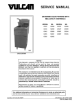
GRA SERIES GAS FRYERS WITH
KLEENSCREEN PLUS®
FILTRATION SYSTEMS
2GR45AF KLEENSCREEN
FRYER BATTERY
MODEL
ML
MODEL
ML
1GR45A
136647
3GR85AF
136655
1GR65A
136648
4GR45AF
136656
1GR85A
136649
4GR65AF
136657
2GR45AF
136650
4GR85AF
136681
2GR65AF
136651
2XGR45AF
136658
2GR85AF
136652
2XGR65AF
136659
3GR45AF
136653
2XGR85AF
136660
3GR65AF
136654
This Manual is prepared for the use of trained Vulcan Service
Technicians and should not be used by those not properly qualified.
This manual is not intended to be all encompassing. If you have not
attended a Vulcan Service School for this product, you should read,
in its entirety, the repair procedure you wish to perform to
determine if you have the necessary tools, instruments and skills
required to perform the procedure. Procedures for which you do not
have the necessary tools, instruments and skills should be
performed by a trained Vulcan Service Technician.
The reproduction, transfer, sale or other use of this Manual, without
the express written consent of Vulcan, is prohibited.
This manual has been provided to you by ITW Food Equipment
Group LLC ("ITW FEG") without charge and remains the property
of ITW FEG, and by accepting this manual you agree that you will
return it to ITW FEG promptly upon its request for such return at
any time in the future.
For additional information on Vulcan-Hart Company or to locate an authorized parts
and service provider in your area, visit our website at www.vulcanhart.com.
A product of VULCAN-HART
LOUISVILLE, KY 40201-0696
F25377 (March 2010)
GRA SERIES GAS FRYERS
TABLE OF CONTENTS
GENERAL . . . . . . . . . . . . . . . . . . . . . . . . . . . . . . . . . . . . . . . . . . . . . . . . . . . . . . . . . . . . . . . . . . . . . . . . . . . . . . . .
Introduction . . . . . . . . . . . . . . . . . . . . . . . . . . . . . . . . . . . . . . . . . . . . . . . . . . . . . . . . . . . . . . . . . . . . . . . . . . . .
Single Floor Model Fryers . . . . . . . . . . . . . . . . . . . . . . . . . . . . . . . . . . . . . . . . . . . . . . . . . . . . . . . . . . . . . . . .
Kleenscreen Filtration System . . . . . . . . . . . . . . . . . . . . . . . . . . . . . . . . . . . . . . . . . . . . . . . . . . . . . . . . . . . . .
Specifications . . . . . . . . . . . . . . . . . . . . . . . . . . . . . . . . . . . . . . . . . . . . . . . . . . . . . . . . . . . . . . . . . . . . . . . . . .
Electrical . . . . . . . . . . . . . . . . . . . . . . . . . . . . . . . . . . . . . . . . . . . . . . . . . . . . . . . . . . . . . . . . . . . . . . . . . .
Gas Pressures . . . . . . . . . . . . . . . . . . . . . . . . . . . . . . . . . . . . . . . . . . . . . . . . . . . . . . . . . . . . . . . . . . . . .
Tools . . . . . . . . . . . . . . . . . . . . . . . . . . . . . . . . . . . . . . . . . . . . . . . . . . . . . . . . . . . . . . . . . . . . . . . . . . . . . . . . .
3
3
3
4
4
4
4
4
REMOVAL AND REPLACEMENT OF PARTS . . . . . . . . . . . . . . . . . . . . . . . . . . . . . . . . . . . . . . . . . . . . . . . . . . . . 5
Splash Guard (Kleenscreen Fryers Only) . . . . . . . . . . . . . . . . . . . . . . . . . . . . . . . . . . . . . . . . . . . . . . . . . . . . . 5
Cooking Controls . . . . . . . . . . . . . . . . . . . . . . . . . . . . . . . . . . . . . . . . . . . . . . . . . . . . . . . . . . . . . . . . . . . . . . . 5
Discard Valve Switch (Kleenscreen Fryers Only) . . . . . . . . . . . . . . . . . . . . . . . . . . . . . . . . . . . . . . . . . . . . . . . 5
Gas Burners . . . . . . . . . . . . . . . . . . . . . . . . . . . . . . . . . . . . . . . . . . . . . . . . . . . . . . . . . . . . . . . . . . . . . . . . . . . 6
Gas Orifice . . . . . . . . . . . . . . . . . . . . . . . . . . . . . . . . . . . . . . . . . . . . . . . . . . . . . . . . . . . . . . . . . . . . . . . . . . . . 7
Gas Combination Valve . . . . . . . . . . . . . . . . . . . . . . . . . . . . . . . . . . . . . . . . . . . . . . . . . . . . . . . . . . . . . . . . . . 7
Gas Pilot . . . . . . . . . . . . . . . . . . . . . . . . . . . . . . . . . . . . . . . . . . . . . . . . . . . . . . . . . . . . . . . . . . . . . . . . . . . . . . 8
Temperature Probe . . . . . . . . . . . . . . . . . . . . . . . . . . . . . . . . . . . . . . . . . . . . . . . . . . . . . . . . . . . . . . . . . . . . . 9
High Limit Thermostat . . . . . . . . . . . . . . . . . . . . . . . . . . . . . . . . . . . . . . . . . . . . . . . . . . . . . . . . . . . . . . . . . . . 9
Power Supply Box Components . . . . . . . . . . . . . . . . . . . . . . . . . . . . . . . . . . . . . . . . . . . . . . . . . . . . . . . . . . . 10
Fill Solenoid Valve (Kleenscreen Fryers Only) . . . . . . . . . . . . . . . . . . . . . . . . . . . . . . . . . . . . . . . . . . . . . . . . 11
Pump and Motor (Kleenscreen Fryers Only) . . . . . . . . . . . . . . . . . . . . . . . . . . . . . . . . . . . . . . . . . . . . . . . . . 11
Fry Tank Assembly . . . . . . . . . . . . . . . . . . . . . . . . . . . . . . . . . . . . . . . . . . . . . . . . . . . . . . . . . . . . . . . . . . . . . 12
SERVICE PROCEDURES AND ADJUSTMENTS . . . . . . . . . . . . . . . . . . . . . . . . . . . . . . . . . . . . . . . . . . . . . . . . .
Temperature Probe Test . . . . . . . . . . . . . . . . . . . . . . . . . . . . . . . . . . . . . . . . . . . . . . . . . . . . . . . . . . . . . . . .
Cooking Control Calibration . . . . . . . . . . . . . . . . . . . . . . . . . . . . . . . . . . . . . . . . . . . . . . . . . . . . . . . . . . . . . .
Electronic Ignition System . . . . . . . . . . . . . . . . . . . . . . . . . . . . . . . . . . . . . . . . . . . . . . . . . . . . . . . . . . . . . . .
Flame Sense Current Check . . . . . . . . . . . . . . . . . . . . . . . . . . . . . . . . . . . . . . . . . . . . . . . . . . . . . . . . . . . . .
Electronic Ignition Control Test . . . . . . . . . . . . . . . . . . . . . . . . . . . . . . . . . . . . . . . . . . . . . . . . . . . . . . . . . . . .
Gas Manifold Pressure Adjustment . . . . . . . . . . . . . . . . . . . . . . . . . . . . . . . . . . . . . . . . . . . . . . . . . . . . . . . .
14
14
15
15
16
16
18
ELECTRICAL OPERATION . . . . . . . . . . . . . . . . . . . . . . . . . . . . . . . . . . . . . . . . . . . . . . . . . . . . . . . . . . . . . . . . . .
Component Function . . . . . . . . . . . . . . . . . . . . . . . . . . . . . . . . . . . . . . . . . . . . . . . . . . . . . . . . . . . . . . . . . . .
Power Supply Box Components . . . . . . . . . . . . . . . . . . . . . . . . . . . . . . . . . . . . . . . . . . . . . . . . . . . . . . . . . . .
Sequence of Operation . . . . . . . . . . . . . . . . . . . . . . . . . . . . . . . . . . . . . . . . . . . . . . . . . . . . . . . . . . . . . . . . .
Kleenscreen Filtering System . . . . . . . . . . . . . . . . . . . . . . . . . . . . . . . . . . . . . . . . . . . . . . . . . . . . . . . . .
Schematic Diagrams . . . . . . . . . . . . . . . . . . . . . . . . . . . . . . . . . . . . . . . . . . . . . . . . . . . . . . . . . . . . . . . . . . .
Fryers Without Kleenscreen Filtration System . . . . . . . . . . . . . . . . . . . . . . . . . . . . . . . . . . . . . . . . . . . .
Fryers with Kleenscreen Filtration System . . . . . . . . . . . . . . . . . . . . . . . . . . . . . . . . . . . . . . . . . . . . . . .
Wiring Diagrams . . . . . . . . . . . . . . . . . . . . . . . . . . . . . . . . . . . . . . . . . . . . . . . . . . . . . . . . . . . . . . . . . . . . . . .
Frymate (Dump Station) . . . . . . . . . . . . . . . . . . . . . . . . . . . . . . . . . . . . . . . . . . . . . . . . . . . . . . . . . . . . .
19
19
21
22
23
24
24
25
26
30
TROUBLESHOOTING . . . . . . . . . . . . . . . . . . . . . . . . . . . . . . . . . . . . . . . . . . . . . . . . . . . . . . . . . . . . . . . . . . . . . .
All Models . . . . . . . . . . . . . . . . . . . . . . . . . . . . . . . . . . . . . . . . . . . . . . . . . . . . . . . . . . . . . . . . . . . . . . . . . . . .
Ignition Module . . . . . . . . . . . . . . . . . . . . . . . . . . . . . . . . . . . . . . . . . . . . . . . . . . . . . . . . . . . . . . . . . . . . . . . .
Frymate (Dump Station) with Optional Heater . . . . . . . . . . . . . . . . . . . . . . . . . . . . . . . . . . . . . . . . . . . . . . . .
Kleenscreen Filtering System . . . . . . . . . . . . . . . . . . . . . . . . . . . . . . . . . . . . . . . . . . . . . . . . . . . . . . . . . . . . .
31
31
32
35
36
© VULCAN 2010
F25377 (March 2010)
Page 2 of 36
GRA SERIES GAS FRYERS - GENERAL
GENERAL
INTRODUCTION
SINGLE FLOOR MODEL FRYERS
This Service Manual covers specific service
information related to the models listed on the front
cover. GRA series gas fryers come equipped with
behind-the-door solid state controls. The features
and operation of the cooking controls are the same
for both single floor model fryers and kleenscreen
battery fryers.
Fryers with the Filter-Ready option installed, use the
Mobile Filter. For service information related to the
Mobile filter refer to F24599 MOBILE FILTERS.
A GRO Frymate (dump station) can be configured in
a battery with fryers 15 1/2 inches or 21 inches in
width.
Model
NO. OF HEAT TUBES
EACH FRY TANK
BTU/HOUR
EACH FRY TANK
FRYER WIDTH
(INCHES)
SHORTENING
CAPACITY (LBS)
EACH FRY TANK
1GR45A
4
120,000
15.5
45-50
1GR65A
5
150,000
21.0
65-70
1GR85A
5
150,000
21.0
85-90
2GR45AF
4
120,000
31.0
45-50
3GR45AF
4
120,000
46.5
45-50
4GR45AF
4
120,000
62.0
45-50
2GR65AF
5
150,000
42.0
65-70
3GR65AF
5
150,000
63.0
65-70
4GR65AF
5
150,000
84.0
65-70
2GR85AF
5
150,000
42.0
85-90
3GR85AF
5
150,000
63.0
85-90
4GR85AF
5
150,000
84.0
85-90
2XGR45AF
4
120,000
31.0
45-50
2XGR65AF
5
150,000
42.0
65-70
2XGR85AF
5
150,000
42.0
85-90
Page 3 of 36
F25377 (March 2010)
GRA SERIES GAS FRYERS - GENERAL
KLEENSCREEN FILTRATION
SYSTEM
TOOLS
Standard
The Kleenscreen filtration system is integrated into
the GRA Series fryer battery. The filter is housed in a
pull-out drawer assembly at the base of the fryer.
The filtering components in the drawer include a
stainless steel filter tank, crumb-catch basket and a
dual element mesh filter screen. With the filter
drawer closed, a self-seating oil return line provides
the path to return the filtered shortening to the fry
tank.
•
Standard set of hand tools.
•
VOM with A/C current tester (any quality VOM
with a sensitivity of at least 20,000 ohms per
volt can be used).
•
Temperature tester (thermocouple type).
•
U-Tube Manometer.
This system is designed to provide a thorough and
easy method to filter the shortening.
•
Field service grounding kit (available locally)
•
OnWatch QuickLook™ 72, checks flame sense
and input voltage to the Honeywell S8600
series ignition control module with an
EnviraCOM™ port.
Some of the benefits include:
•
Self-contained system eliminating the use of
external filter equipment.
•
Paperless filtering system.
•
Easy to clean and low maintenance.
Special
Kleenscreen fryer batteries are available in a
minimum of two and a maximum of four fryer
sections. The fryer size of each section is identical.
A GRO Frymate (dump station) can also be included
as one or more of the sections.
SPECIFICATIONS
Electrical
•
120VAC supply. A 24VAC transformer provides
power for the fryer controls and the filtering
controls on Kleenscreen battery fryers.
You can order the QuickLook™ 72 on line at
www.onwatchinc.com. The OnWatch Combo
Item #721014 includes both the QuickLook™ 72
and a 3 ft. data port extension cable.
Gas Pressures
Manifold (per fryer section):
•
Natural - 4" W.C.
•
Propane - 10" W.C.
•
Building supply pressure (Min):
•
Natural - 5" W.C. (7" W.C. battery units)
•
Propane - 11" W.C. (12" W.C. battery units)
NOTE: Propane or Natural gases -14" W.C. (Max)
F25377 (March 2010)
Page 4 of 36
Burndy pin extraction tool RX2025 GE1;
Newark Electronics Catalog Number 16F6666.
Used for removing pin terminals on Burndy
connectors.
GRA SERIES GAS FRYERS - REMOVAL AND REPLACEMENT OF PARTS
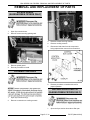
REMOVAL AND REPLACEMENT OF PARTS
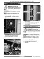
SPLASH GUARD
(KLEENSCREEN FRYERS ONLY)
1.
Open fryer section doors.
2.
Remove screws securing splash guard.
3.
Remove splash guard.
4.
Reverse procedure to install.
3.
Remove screws securing controls.
4.
Remove cooking controls.
5.
Disconnect lead wires from the component
being replaced then remove from control box.
6.
Reverse procedure to install and check for
proper operation.
COOKING CONTROLS
DISCARD VALVE SWITCH
(KLEENSCREEN FRYERS ONLY)
1.
Open fryer section door(s).
2.
Remove connections to cooking controls.
1.
Page 5 of 36
Open the fryer section doors above filter pan.
F25377 (March 2010)
GRA SERIES GAS FRYERS - REMOVAL AND REPLACEMENT OF PARTS
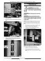
2.
Pull filter drawer out, remove filter tank
assembly and push the tank support arms back
into place under the fryer.
3.
Remove splash guard from base frame.
4.
From underneath the fryer:
5.
A.
Disconnect the discard valve switch lead
wire connector from power supply box.
B.
Remove switch mounting screws.
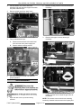
2.
Remove cooking controls to access burner(s) if
necessary.
3.
Remove drain pipe to access burner(s) if
necessary.
4.
Remove gas burner shipping ties (if installed).
5.
Lift gas burner up and tilt the top of burner
toward fryer tank until it clears the gas orifice at
the bottom.
Reverse procedure to install and check for
proper operation.
GAS BURNERS
1.
Open the door to the fryer section being
serviced.
F25377 (March 2010)
NOTE: The burners mount to the burner mounting
bracket by shoulder bolts that rest in the keyway slot.
Page 6 of 36
GRA SERIES GAS FRYERS - REMOVAL AND REPLACEMENT OF PARTS
2.
Reverse procedure to install and check for
proper operation.
GAS COMBINATION VALVE
6.
Remove burner.
7.
Reverse procedure to install and check for
proper operation.
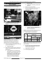
GAS ORIFICE
NOTE: If a gas combination valve is malfunctioning,
do not attempt to disassemble the valve for repair.
Install a replacement gas combination valve.
1.
1.
Remove GAS BURNERS.
2.
Disconnect lead wires from gas combination
valve.
Remove gas orifice spud from orifice extension.
The spud screws into orifice extension.
When installing, do not over tighten the spud or
damage to the threads may occur.
Page 7 of 36
F25377 (March 2010)
GRA SERIES GAS FRYERS - REMOVAL AND REPLACEMENT OF PARTS
3.
Disconnect pilot tube from gas combination
valve.
4.
Disconnect gas line fittings then remove gas
combination valve.
A.
5.
Remove gas line fittings from gas
combination valve and install (in same
orientation) on the replacement valve.
Reverse procedure to install and check for
proper operation.
A.
Clean the pipe threads and apply pipe joint
compound to threads. Any pipe joint
compound used must be resistant to the
action of propane gases.
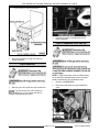
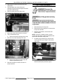
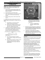
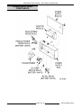
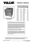
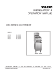
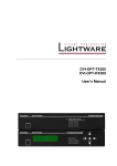
GAS PILOT
1.
Remove GAS BURNERS as necessary.
2.
Remove pilot burner assembly and bracket from
pilot bracket stand-off on the fry tank.
4.
Disconnect pilot tube from gas pilot.
5.
Remove screws (2) securing gas pilot to
mounting bracket.
A.
To remove gas orifice from pilot for
inspection or cleaning, disconnect the gas
orifice fitting from pilot body.
B.
If orifice is clogged with debris, clean with
air or liquid only.
GAS PILOT FOR ELECTRONIC IGNITION SHOWN
6.
Reverse procedure to install and check for
proper operation.
A.
3.
Remove wire tie and disconnect ignitor cable
from ignitor/flame sense electrode on the gas
pilot.
F25377 (March 2010)
Page 8 of 36
Secure ignitor to pilot tube with wire tie.
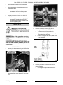
GRA SERIES GAS FRYERS - REMOVAL AND REPLACEMENT OF PARTS
and probe to the fryer heat tube (inside tank)
then remove probe.
TEMPERATURE PROBE
Do not sharply bend and kink, or clamp
down on the capillary tube or damage may occur.
1.
Drain shortening from fryer tank.
2.
Disconnect smaller, 6-pin male connector.
(Temperature probe and drain valve interlock
(DVI) connector)
7.
Reverse procedure to install and check for
proper operation.
8.
Check COOKING CONTROL CALIBRATION
under SERVICE PROCEDURES AND
ADJUSTMENTS.
HIGH LIMIT THERMOSTAT
3.
Remove the temperature probe lead wires from
pins 1 and 3 of the 6-pin male connector.
4.
Remove GAS BURNERS as necessary.
5.
Remove the probe retaining and packing nuts.
6.
Do not sharply bend and kink, or clamp
down on the capillary tube or damage may occur.
1.
Drain shortening from fryer tank.
2.
Remove GAS BURNERS as necessary.
3.
Disconnect lead wires from high limit
thermostat.
Remove screws securing probe mounting clips
Page 9 of 36
F25377 (March 2010)
GRA SERIES GAS FRYERS - REMOVAL AND REPLACEMENT OF PARTS
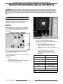
POWER SUPPLY BOX
COMPONENTS
4.
Remove screws securing the high limit to
mounting bracket.
5.
Remove the capillary tube retaining and packing
nuts.
6.
NOTE: The power supply box must be removed to
access the following components: Ignition control
module, transformer, R1 pump motor relay, R2 fill
relay.
1.
Disconnect all wiring harness connectors and
power cords from power supply box.
2.
From rear, remove screw securing power
supply box to mounting bracket.
Remove screws securing mounting clips and
capillary tube to the fryer heat tube (inside tank)
then remove capillary tube.
NOTE: Power supply box is slotted at the front and
secured by a hanging bracket (loose fit).
7.
3.
Remove cover from power supply box.
4.
Disconnect lead wires from the component
being replaced then remove from power supply
box.
Reverse procedure to install.
F25377 (March 2010)
Page 10 of 36
GRA SERIES GAS FRYERS - REMOVAL AND REPLACEMENT OF PARTS
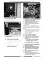
4.
5.
Disconnect swivel pipe fitting at rear of fry tank.
Reverse procedure to install and check for
proper operation.
FILL SOLENOID VALVE
(KLEENSCREEN FRYERS ONLY)
REAR VIEW SHOWN
5.
Disconnect fill solenoid valve lead wire
connector (4 pin) from power supply box.
6.
Remove screws (2) securing the solenoid valve
body flange to pipe tee then remove the
assembly from fryer.
A.
1.
Open the fryer section doors above filter pan.
2.
Pull filter drawer out, remove filter tank
assembly and push the tank support arms back
into place under the fryer.
3.
Remove splash guard.
7.
Remove pipe fittings from solenoid valve
and install on replacement valve.
Reverse procedure to install and check for
proper operation.
PUMP AND MOTOR
(KLEENSCREEN FRYERS ONLY)
1.
Page 11 of 36
Drain filter tank of shortening.
F25377 (March 2010)
GRA SERIES GAS FRYERS - REMOVAL AND REPLACEMENT OF PARTS
2.
Open the fryer section doors above the filter
tank drawer.
3.
Pull filter drawer out, remove filter tank
assembly and push the tank support arms back
into place under the fryer.
4.
Remove splash guard from base frame.
5.
Disconnect pump motor lead wire connector.
6.
From underneath the fryer:
A.
7.
8.
Disconnect flexible line fittings from pump.
Remove pump motor assembly from fryer.
A.
FRY TANK ASSEMBLY
Remove pipe fittings from the pump and
install on replacement pump.
1.
Drain shortening from fryer tank.
2.
Disconnect the gas supply line to allow access
to fryer from all sides.
3.
Remove fryer baskets, crumb screen and
basket hanger.
NOTE: If the fryer is a battery section, remove
grease strip and split the silicone seal between the
fryer section tanks with a utility knife.
4.
On battery fryer sections only, remove bolts
securing the drain pipe flange to the manual
drain valve.
5.
Disconnect temperature probe and drain valve
interlock switch (DVI) connector (6 pin).
Reverse procedure to install and check for
proper operation.
F25377 (March 2010)
Page 12 of 36
GRA SERIES GAS FRYERS - REMOVAL AND REPLACEMENT OF PARTS
6.
Remove POWER SUPPLY BOX.
7.
On battery fryer sections only, remove splash
guard from base frame.
9.
Disconnect swivel fitting from fry tank at the rear
(shortening line inlet to fry tank).
10. Disconnect flexible gas line fitting at manual
shutoff valve (gas supply inlet to valve).
11. Remove screws securing the top of fry tank to
the flue wrap.
NOTE: Remove wire ties securing lead wires and
wiring harnesses as necessary before removing fry
tank; and when removing components from fry tank
for reuse.
12. Grasp the fry tank at the top (by flue) and front
lip, then lift fry tank assembly from the fryer
body. Place the assembly on floor or table for
removal of components.
13. Remove GAS PILOT.
14. Remove TEMPERATURE PROBE.
8.
Remove gas manifold and frame assembly from
the fryer<s base frame:
A.
Remove gas burners as necessary.
B.
For the fryer sections above the filter
drawer assembly on battery fryers or single
floor model fryers, remove mounting nuts
securing gas manifold and frame assembly
to the fryer’s base frame.
C.
For all other fryer sections in a battery only,
remove mounting nuts securing gas
manifold and frame assembly to the V
shaped frame support bracket.
15. Remove HIGH LIMIT THERMOSTAT.
16. On battery fryer sections only, when removing
fry tank from sections with the mechanical
discard valve:
A.
Loosen u-bolt securing discard pipe with
male quick disconnect fitting to the
mounting bracket.
B.
Remove pipe from elbow on mechanical
discard valve.
17. Remove bolts securing gas manifold and frame
assembly to the fry tank.
18. Pull the gas manifold assembly from fry tank.
19. Disconnect drain valve interlock switch (DVI)
connector (2 pin) and remove manual drain
valve.
20. Remove screws securing flue box to fry tank
then remove flue box.
21. Reverse procedure to install all the parts
removed from original fry tank onto replacement
fry tank, then install the assembly.
Page 13 of 36
F25377 (March 2010)
GRA SERIES GAS FRYERS - SERVICE PROCEDURES AND ADJUSTMENTS
SERVICE PROCEDURES AND ADJUSTMENTS
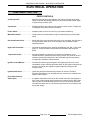
TEMPERATURE PROBE TEST
The temperature probe is an RTD (resistance
temperature detector) of the thermistor type. As
temperature increases the resistance value
decreases.
Probe Fault
If a temperature probe fault occurs, red diagnostic
LED on back of control assembly (inside control box
cover) will flash. The heat demand outputs are
de-activated.
3.
Test the probe using a VOM to measure
resistance. Connect the meter leads to pins 1 &
3 on the male connector.
This will continue until the fault clears, power is
cycled or problem resolved.
A temperature probe fault can be caused by a lead
break or a lead short.
Turn power switch off.
2.
Disconnect the temperature probe & the drain
valve interlock (DVI) connector.
If the measured resistance values are
within the allowable range, the probe is
functioning properly. Reverse procedure to
install.
B.
If the measured resistance values are
outside the allowable range, install a
replacement probe and check for proper
operation.
Temperature (ºF)
Resistance (Ω)
32
315,915 - 386,119
77
90,000 - 110,000
212
5,016 - 6,130
275
1,804 - 2,204
300
1,254 - 1,534
350
604 - 836
460 1
191 - 233
To Check:
1.
A.
NOTE: 1. Shorted probe equivalent temperature.
F25377 (March 2010)
Page 14 of 36
GRA SERIES GAS FRYERS - SERVICE PROCEDURES AND ADJUSTMENTS
COOKING CONTROL
CALIBRATION
NOTE: Verify condition of temperature probe as
outlined under TEMPERATURE PROBE TEST
before proceeding.
1.
Check the level of shortening in fry tank. The
level must be between the MIN & MAX fill lines
before proceeding.
2.
Allow shortening to cool below 300EF.
3.
Place a thermocouple in the geometric center of
the fry tank one inch below the shortening
surface.
4.
Set the cooking control to 350EF and turn the
fryer on.
5.
Monitor the burners as they cycle on and off.
1)
NOTE: Agitate the shortening, to eliminate any cold
zones.
A.
B.
6.
Allow burners to cycle three times to
stabilize shortening temperature.
a.
Record meter reading from thermocouple
when the burners cycle off and on for at
least two complete heating cycles.
Calculate the average temperature by adding
the temperature reading when the burners go
out to the temperature reading when the
burners come on & divide this answer by 2.
Repeat the average temperature calculation for
up to three attempts. Allow the cooking control
to cycle at least two times between adjustments
before performing the calculation.
8.
If calibration is unsuccessful, the cooking
control may be malfunctioning and cannot be
adjusted properly. Install a replacement cooking
control and check calibration.
Example: 360° + 340° ÷ 2 = 350°F.
The average temperature should be
350EF (± 5EF).
B.
If over 25E of adjustment is
necessary, replace cooking
control.
7.
[ Temp. (Burners off) + Temp. (Burners on) ] ÷ 2 = Average
Temp.
A.
Adjust calibration potentiometer
clockwise to increase temperature,
and counterclockwise to decrease
temperature.
ELECTRONIC IGNITION SYSTEM
If the average temperature reading is
within tolerance, cooking control is properly
calibrated.
If the average temperature reading is out of
tolerance, loosen set screw to remove
temperature knob and adjust calibration
potentiometer.
Operation
When the main power switch is turned on the ignition
control module is energized with 24 volts between
terminals 5 and 6.
An output of 24 volts is sent from terminals 2 and 3
to the pilot coil on the combination valve, allowing
gas flow to the pilot; and spark voltage is sent from
SPARK terminal to begin sparking at the
ignitor/flame sense electrode. The sparking will
continue until an adequate pilot flame is sensed or
for a maximum of 90 seconds.
If pilot is not established within the 90 second ignition
trial time, the ignition module locks out power to the
gas valve. Controls will be disabled.
The system remains locked out until the power
switch is cycled to reset the system and re-start the
ignition trial cycle.
Once the pilot flame is confirmed, a 24 volt output
from terminal 1 will provide the ignition status input
signal to the cooking control. When the cooking
Page 15 of 36
F25377 (March 2010)
GRA SERIES GAS FRYERS - SERVICE PROCEDURES AND ADJUSTMENTS
control calls for heat, the heat output is activated and
the main valve coil on the combination valve is then
energized, allowing gas flow to the burners.
Terminal
Description
1
MV (main voltage) - 24VAC output
will be present, providing the
ignitor/flame sense electrode is
sensing an adequate pilot fame.
2
MV/PV (common).
3
PV (pilot voltage) - 24VAC output
will be present after the ignition
module is powered. The voltage will
remain present, providing an
adequate pilot flame is sensed. If the
pilot flame is not sensed within the
ignition trial time, the ignition module
locks out which removes the output
voltage.
4
Burner ground.
5
24VAC ground.
6
24VAC hot (input).
4.
A.
If reading is greater than or equal to the
value given, then flame sense current is
within tolerance.
NOTE: Yellow Flame LED next to port should show
continuous 1/2 second on-1/2 second off heartbeat.
B.
FLAME SENSE CURRENT
CHECK
If reading is less than the value given,
perform ELECTRONIC IGNITION
CONTROL TEST.
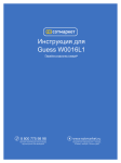
ELECTRONIC IGNITION
CONTROL TEST
1.
Turn the power switch OFF.
2.
Access the ignition control module in the power
supply box and locate the EnviraCom™ port.
3.
Meter reading should be above 1.0 micro amp
(minimum) and steady.
If the ignition control module is not generating a
spark to ignite gas pilot, perform the following
checks.
1.
Access the ignition control module in the power
supply box and locate the EnviraCom™ port.
2.
Connect the QuickLook™ 72 meter to the
EnviraCom™ port.
Connect the QuickLook™ 72 meter to the
EnviraCom™ port. Turn power switch ON.
F25377 (March 2010)
Page 16 of 36
GRA SERIES GAS FRYERS - SERVICE PROCEDURES AND ADJUSTMENTS
3.
4.
Turn the power switch on and verify the ignition
control module is receiving power from the
transformer.
A.
If 24VAC is present, then module is
receiving power. Turn the power switch off
and continue with procedure.
B.
If 24VAC is not present then find the
source of the problem.
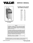
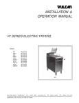
ELECTRONIC IGNITION GAS PILOT SHOWN
D.
Disconnect power to the machine.
5.
Verify all electrical connections on the ignition
control module are secure.
6.
Verify the ground wire connections on the
ignition control module and the gas pilot
mounting bracket are clean and secure. The
gas pilot should have good metal to metal
contact to the pilot mounting bracket on the
fryer.
7.
8.
With gas pilot installed and the ignitor cable
connected, reconnect power and turn the gas
supply on.
9.
Turn power switch on and observe spark from
ignitor.
A.
If spark from ignitor is present and ignites
the gas for the pilot, and burners light, then
the system is working properly.
B.
If gas pilot lights but does not maintain an
adequate flame during the trial for ignition
(90 sec.), check pilot orifice for clogging.
NOTE: If orifice is clogged with debris, clean with air
or water only.
Remove the gas pilot and check the following:
A.
Check the ignitor cable connection for
tightness and damaged insulation. If the
ignitor cable appears to be damaged, then
install a replacement ignitor cable.
C.
Inspect the ceramic insulator on the
ignitor/flame sense electrode for cracks or
evidence of exposure to extreme heat,
which can permit leakage to ground. If
either of these conditions exist, then install
a replacement gas pilot.
B.
Inspect the ignitor electrode and ground
clip for contaminates, or corrosion. Clean
those surfaces as necessary.
C.
The gap between the ignitor/flame sense
electrode and the ground clip should be 1/8
inch. If the gap is outside of this dimension,
bend the ground clip as necessary, to
make the adjustment.
If spark from ignitor is present but does not
ignite pilot gas before the ignition control
module locks out, there may not be enough
gas in the line for ignition.
Turn the power switch off to re-set the
module. Wait 5 minutes between ignition
tries for unburned gas to vent. Turn the
power switch on and sparking should
resume to ignite pilot. The module may
need re-set several times before ignition
takes place.
D.
If ignitor is still not sparking, turn the power
switch off, disconnect power and turn the
gas supply off.
10. Install a replacement ignition control module
and check for proper operation.
Page 17 of 36
F25377 (March 2010)
GRA SERIES GAS FRYERS - SERVICE PROCEDURES AND ADJUSTMENTS
adequate sizing.
GAS MANIFOLD PRESSURE
ADJUSTMENT
1.
2.
B.
Open the door(s) and remove drain pipe.
If adjustment is necessary, continue with
procedure.
5.
Remove burners as necessary.
6.
Remove the adjustment screw cap to access
the pressure adjustment screw on gas
combination valve.
To measure the manifold pressure, remove plug
and attach manometer to pressure tap in
manifold.
A.
To increase pressure, turn the screw
clockwise. To decrease pressure, turn the
screw counterclockwise.
NOTE: Accurate gas pressure adjustments can only
be made with the gas on and the burner lit.
7.
Set the pressure as outlined below:
GAS
TYPE
NOTE: Gas manifold pressure can also be
measured by removing the 1/8 inch NPT plug
(pressure tap) on the outlet side of the gas
combination valve and attaching a manometer.
3.
Turn the gas supply, gas combination valve and
the main power switch to on.
A.
4.
A.
LINE
RECOMMENDED
MIN MAX
4
7
5
Propane
10
11
11
14
NOTE: If the incoming line pressure is less than the
minimum stated, then the manifold pressure can not
be set correctly.
8.
Once the correct pressure has been set, turn
the power switch off, replace the adjustment
screw cap and manifold plug.
9.
Install drain pipe and burners.
10. Check for proper operation.
If other appliances are connected to the
same gas line, turn them all on and check
manometer pressure reading again. If a
pressure drop of 1/2 inch water column or
more is observed, then the gas supply
needs to be checked by the gas line
installer or the local gas company for
F25377 (March 2010)
MANIFOLD
Natural
Verify burners light.
Observe the manometer pressure reading and
compare to the pressure chart near the end of
this procedure.
PRESSURE READINGS
(INCHES W.C.)
Page 18 of 36
GRA SERIES GAS FRYERS - ELECTRICAL OPERATION
ELECTRICAL OPERATION
COMPONENT FUNCTION
FRYER CONTROLS
Cooking Control . . . . . . . . . . . . . . Monitors and evaluates input signals to the control: Activates heat output
signal to maintain shortening temperature; and activates filter output signal
to power the fill solenoid valve.
Transformer . . . . . . . . . . . . . . . . . Supplies 24VAC to the cooking control ignition control module. Transformer
is energized when power switch is turned on.
Power Switch . . . . . . . . . . . . . . . . Supplies power to control circuit for fryer operation and filtering.
Melt Select Switch . . . . . . . . . . . . Controls burner operation based on type of shortening being used (liquid/
solid).
Gas Combination Valve . . . . . . . . Allows gas flow to the pilot when pilot valve coil is energized; and gas flow to
the burners when main valve coil is energized. Also, regulates the gas
manifold pressure.
High Limit Thermostat . . . . . . . . . Prevents the shortening from reaching temperatures over 450EF (auto reset
@ 415°F, normal operation resumes when temperature falls below this
point).
Temperature Probe . . . . . . . . . . . Senses temperature of shortening. Converts the temperature into a
resistance which is monitored by the cooking control. The probe is an RTD
(resistance temperature detector) of the Thermistor type. As temperature
increases the resistance value decreases.
Ignition Control Module . . . . . . . . Controls and monitors gas pilot ignition. Energizes pilot valve coil on the
combination control valve and generates spark for pilot ignition. Monitors the
presence of a flame and supplies an ignition status input signal to the
cooking control.
Ignitor/Flame Sense . . . . . . . . . . . Ignites the gas pilot and senses the presence of a flame. The flame
presence generates a micro-amp flame sense current that is rectified to the
ignition control module.
Drain Valve Interlock
Switch (DVI) . . . . . . . . . . . . . . . . . A magnetic reed switch mounted on the manual drain valve that supplies a
drain valve position signal (open/closed) to the cooking control. When drain
valve is open, the drain interlock input to the control is removed (magnetic
reed switch contacts open). This prevents gas burners from coming on with
the fry tank empty.
Page 19 of 36
F25377 (March 2010)
GRA SERIES GAS FRYERS - ELECTRICAL OPERATION
KLEENSCREEN FILTER CONTROLS
Fill Solenoid Valve . . . . . . . . . . . . When energized by filter switch, the solenoid valve opens to allow the flow of
shortening thru filtering system.
Pump Motor . . . . . . . . . . . . . . . . . Operates pump to circulate shortening through filtering system.
Start Switch . . . . . . . . . . . . . . . . . . Supplies power to temperature control module.
Filter Switch . . . . . . . . . . . . . . . . . Supplies power to pump motor thru R1 and fill solenoid valve thru R2.
Discard Valve Switch . . . . . . . . . . A magnetic reed switch mounted on the mechanical discard valve that
closes when discard valve handle is extended to discard the shortening.
Prevents R2 filter relay N.C. contacts from suppling power to the fill solenoid
valve when filter key is pressed.
R1 Pump Motor Relay . . . . . . . . . When 24VAC relay coil is energized by filter switch, supplies 120VAC to
pump motor; and fill solenoid valve thru R2 fill relay N.C. contacts.
R2 Fill Relay . . . . . . . . . . . . . . . . . When 24VAC relay coil is energized by filter switch, supplies 24VAC to the
fill solenoid valve to open the valve and allow shortening to flow thru filter
system.
F25377 (March 2010)
Page 20 of 36
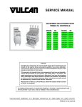
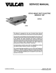
GRA SERIES GAS FRYERS - ELECTRICAL OPERATION
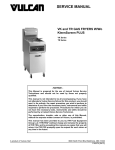
POWER SUPPLY BOX
COMPONENTS
Page 21 of 36
F25377 (March 2010)
GRA SERIES GAS FRYERS - ELECTRICAL OPERATION
SEQUENCE OF OPERATION
Refer to schematic diagram AI 2727 for Cooking Control operation.
NOTE: Make sure melt select switch reflects type of shortening being used (solid/liquid).
1.
2.
Conditions.
A.
Fryer connected to correct supply voltage and properly grounded.
B.
Gas supply is on and gas combination valve is open.
C.
Power switch to the fryer section in the off position.
D.
Shortening at proper level in fry tank and below last set point temperature used.
E.
Manual drain valve closed (drain valve interlock switch N.O. is closed).
F.
High limit thermostat closed.
Turn power switch on.
A.
3.
24VAC transformer energized.
Ignition module is powered (24VAC), initializes and generates spark at ignitor.
A.
B.
Pilot voltage (PV) N.O. contacts close, pilot valve coil energized and valve opens for gas flow to pilot.
1)
Pilot flame established. A micro amp flame sense current is rectified to ignition module through
ignitor cable and sparking stops.
2)
Main voltage (MV) N.O. contacts close and provides ignition status input signal (24VAC) to cooking
control.
If pilot is not established within 90 seconds of the ignition module being energized, the ignition module
locks out power to gas valve.
1)
4.
The system remains locked out until the power switch is cycled to reset the system and re-start the
ignition trial cycle. (wait 5 minutes for gas to dissipate)
Cooking control evaluates input signals from: Ignition status; Drain valve interlock; and temperature probe.
A.
Main valve coil energized and valve opens for gas flow to burners.
1)
Burners light and heat the shortening in fry tank.
NOTE: As long as the ignition control module senses a pilot flame, the internal main voltage (MV)
contacts (N.O.) on the ignition module remain closed, and main gas valve stays on.
5.
Shortening reaches set temperature.
A.
Cooking control de-activates the heat output (24VAC).
1)
Main valve coil de-energized and valve closes.
2)
Gas flow stops and burners go out.
6.
Cooking control cycles heat output on shortening temperature until: power switch is turned off; ignition input
status is removed; drain valve interlock input status is removed; temperature probe input is outside
acceptable limits or a high limit condition occurs.
7.
If shortening reaches 450EF or higher: high limit thermostat opens, power is removed from the pilot valve coil
and valve closes to stop pilot gas flow.
A.
Ignition trial cycle will start but pilot will be unable to light.
B.
Fryer operation can resume when the temperature drops below 415°F.
F25377 (March 2010)
Page 22 of 36
GRA SERIES GAS FRYERS - ELECTRICAL OPERATION
Kleenscreen Filtering System
Refer to schematic diagram AI 2728 for Kleenscreen Filter System operation. Refer to Installation & Operation
manual and Kleenscreen Filtration System Supplement manual for specific instructions on filtering.
NOTE: The discard valve handle is connected to a mechanical valve and magnetic reed switch assembly to route
the flow of shortening in the filtering system and supply power to the pump motor.
1.
Conditions.
A.
Fryer connected to correct supply voltage and is properly grounded .
B.
Power switch to fryer section to filter turned on.
C.
The cooking control should be setup properly and ready to use.
D.
Cooking control temperature setting between 300°F (minimum) and 350°F (maximum).
NOTE: Shortening should not be filtered outside of this temperature range. At lower temperatures the
shortening is thicker which may increase filtering time and place a greater load on the pump. At higher
shortening temperatures, oil seal life is decreased.
E.
Filter drawer assembly installed properly.
F.
Discard valve handle (yellow) retracted.
1)
2.
Discard valve switch N.O. contacts open. Mechanical discard valve closed.
Allow shortening to cycle between 300°F and 350°F for approximately 10 minutes.
NOTE: If using solid shortening, once it has melted, stir the shortening to eliminate any solid shortening in cold
zone of the fry tank.
3.
Open the drain valve to the fryer section in need of filtering and drain the shortening into filter tank.
A.
Drain valve interlock contacts open and the position of the drain valve is indicated to the cooking control.
NOTE: If using solid shortening, allow hot shortening to stand in filter tank for approximately 6 minutes prior to
filtering.
4.
Turn filter switch on cooking controls to ON.
A.
R1 pump motor relay coil (24VAC) is energized and both sets of N.O. contacts close.
NOTE: Jumper wire number 24 connects one set of R1 N.O. contacts to R2 COM.
5.
Fill solenoid valve is energized (120VAC) thru R2 fill relay N.C. contacts and valve opens.
2)
Pump motor is energized (120VAC) and pump circulates shortening through filtering system.
When filtering is completed, close the drain valve and allow the fry tank to refill.
A.
6.
1)
Drain valve interlock contacts close and the position of the drain valve is indicated to the cooking control.
When all filtered shortening is returned to the fry tank, turn filter switch on cooking controls to OFF.
A.
Power is removed from fill solenoid valve and pump motor.
NOTE: If using solid shortening, when all filtered shortening is returned to the fry tank and pump motor is off,
open the filter drawer approximately one inch. Allow the remaining shortening in the line to drain into the filter
tank to prevent possible clogging after the shortening cools and solidifies. Close the filter drawer when
complete.
Page 23 of 36
F25377 (March 2010)
GRA SERIES GAS FRYERS - ELECTRICAL OPERATION
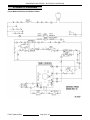
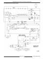
SCHEMATIC DIAGRAMS
Fryers Without KleenScreen Filtration System
F25377 (March 2010)
Page 24 of 36
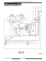
GRA SERIES GAS FRYERS - ELECTRICAL OPERATION
Fryers With KleenScreen Filtration System
Page 25 of 36
F25377 (March 2010)
GRA SERIES GAS FRYERS - ELECTRICAL OPERATION
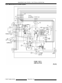
WIRING DIAGRAMS
Fryers Without KleenScreen Filtration System
F25377 (March 2010)
Page 26 of 36
GRA SERIES GAS FRYERS - ELECTRICAL OPERATION
Page 27 of 36
F25377 (March 2010)
GRA SERIES GAS FRYERS - ELECTRICAL OPERATION
Fryers With KleenScreen Filtration System
F25377 (March 2010)
Page 28 of 36
GRA SERIES GAS FRYERS - ELECTRICAL OPERATION
Page 29 of 36
F25377 (March 2010)
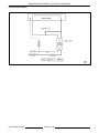
GRA SERIES GAS FRYERS - ELECTRICAL OPERATION
Frymate (Dump Station)
F25377 (March 2010)
Page 30 of 36
GRA SERIES GAS FRYERS - TROUBLESHOOTING
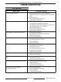
TROUBLESHOOTING
ALL MODELS
SYMPTOMS
No spark to ignite pilot gas.
POSSIBLE CAUSES
1.
2.
3.
4.
5.
Drain valve switch open or switch malfunction.
Shorted electrode or an improper ground on ignitor/flame
sense.
Ignitor cable open.
Interconnecting wiring malfunction.
Ignition Module malfunction.
Sparks but gas does not ignite.
1.
2.
3.
4.
5.
6.
7.
Service gas valve closed.
Gas supply off or insufficient gas pressure.
Gas supply quick disconnect coupling not properly mated.
Gas combination valve off or inoperative.
High limit thermostat open.
Interconnecting wiring malfunction.
Ignition Module malfunction.
Gas pilot ignites but will not maintain flame.
1.
2.
3.
4.
Ignitor ground inoperative.
Ignitor/flame sense misaligned or malfunction.
Insufficient gas pressure.
Ignition module malfunction.
Gas burners ignite but will not maintain flame.
1.
2.
3.
4.
Gas pressure incorrect.
Gas orifice obstructed or incorrect.
Burner malfunction.
Gas pilot malfunction.
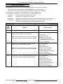
Excessive or low heat.
1.
2.
3.
4.
5.
6.
Cooking controls need calibrated.
Temperature probe malfunction.
Gas pressure incorrect.
Gas orifice obstructed or incorrect.
Cooking control malfunction.
Interface board malfunction.
Intermittent problems.
1.
2.
High ambient temperatures.
Wiring connections loose.
No power to cooking control, fryer does not
heat.
1.
2.
3.
Power switch off or malfunction.
Transformer inoperative.
Interconnecting wiring malfunction.
High limit thermostat shutting off gas burners.
1.
2.
3.
4.
Shortening level below minimum fill line.
Probe malfunction.
Cooking control malfunction.
High limit thermostat malfunction.
Excessive time to melt shortening
(more than 45 minutes).
1.
2.
3.
4.
Insufficient gas pressure.
Gas orifice plugged or obstructed.
Probe malfunction.
Cooking control malfunction.
Page 31 of 36
F25377 (March 2010)
GRA SERIES GAS FRYERS - TROUBLESHOOTING
IGNITION MODULE
The ignition module has two LED's; one for flame sensing and one for ignition system status.
•
Flame LED (Yellow) - Indicates pilot burner flame presence and signal strength.
•
Status LED (Green) - Indicates ignition system operation status and error conditions.
LED Flash Code Descriptions - Flame LED (yellow) or Status LED (green):
•
Fast Flash
- Rapid blinking during startup and self check.
•
Heartbeat
- Cycles bright 1/2 second; dim 1/2 second.
•
Single Flash
- LED flashes X times at 2Hz, remains off for two seconds then repeats flash sequence.
•
Double Flash - LED flashes X times at 2Hz, remains off for two seconds, flashes Y times at 2Hz,
remains off for three seconds then repeats flash sequence (X+Y).
FLAME LED CODES (YELLOW) - PART NO. 857207-1 IGNITION MODULE
LED
Flash
Code
Indicates
Possible Causes
Heartbeat Normal pilot flame signal
2
None
Weak pilot flame signal. Ignition system will operate
reliably but flame signal is less than desired.
NOTE: Code may flash temporarily just after pilot burner
lights then operate normally after flame signal stabilizes.
1
Marginal pilot flame signal (less than 2 µA). Ignition
system may not operate reliably over time.
NOTE: Code may flash temporarily just after pilot burner
lights then operate normally after flame signal stabilizes..
OFF
No pilot flame or flame sense signal below minimum for
ignition system operation. Pilot burner spark is good.
F25377 (March 2010)
Page 32 of 36
Check the following:
1. Gas supply.
2. Pilot burner flame.
3. Spark/flame sense wiring.
4. Flame sense electrode
contaminated or out of position.
5. Pilot burner ground.
Check the following:
1. Gas supply.
2. Pilot burner flame.
3. Spark/flame sense wiring.
4. Flame sense electrode
contaminated or out of position.
5. Pilot burner ground.
6. Ignition module malfunction.
Check the following:
1. Gas supply.
2. Pilot burner flame.
3. Spark/flame sense wiring.
4. Flame sense electrode
contaminated or out of position.
5. Pilot burner ground.
6. Ignition module malfunction.
GRA SERIES GAS FRYERS - TROUBLESHOOTING
IGNITION SYSTEM STATUS LED CODES (GREEN) - PART NO. 857207-1
SINGLE TRY LOCKOUT IGNITION MODULE
LED Flash
Code
OFF
Indicates
System Action
Possible Causes
No Call for Heat
None
None
Fast Flash
Startup
- Pilot flame sense
calibration
Flame sense calibration
automatically occurs immediately
after pilot lights.
None
Heartbeat
Normal operation
None
None
3
Restart ignition trial
- Pilot flame failed
while main burner
on
Trial for ignition auto re-starts. Flash
code will remain through the ignition
trial until pilot flame is proved.
If pilot burner fails to light on
next trial for ignition - check:
1. Gas supply.
2. Pilot burner.
3. Spark/flame sense wiring.
4. Flame sense electrode
contaminated or out of
position.
5. Pilot burner ground.
4
Pilot flame sensed out
of sequence
If ignition system self corrects within
10 seconds, ignition module returns
to normal operation. If flame sense
out of sequence continues, module
changes to Flash Code 6+4.
1. Check pilot burner.
A.
If pilot flame present,
replace gas valve. If
no pilot flame, cycle
Call for Heat, or
power.
B.
If error repeats
(continual or
intermittent), replace
ignition module.
7
Pilot flame sense
leakage to ground
Module will not proceed to trial for
ignition. When fault is corrected,
module resumes trial for ignition,
after a one minute delay.
1. Check spark/flame sense
wiring.
2. Check flame sense
electrode position.
3. Check flame sense
electrode ceramic for
cracks.
Page 33 of 36
F25377 (March 2010)
GRA SERIES GAS FRYERS - TROUBLESHOOTING
IGNITION SYSTEM STATUS LED CODES (GREEN) - PART NO. 857207-1
SINGLE TRY LOCKOUT IGNITION MODULE
LED Flash
Code
8
Indicates
System Action
Possible Causes
Low voltage to ignition
module
- Below 15.5 VAC
Module will not proceed to trial for
ignition. When fault is corrected,
module resumes trial for ignition,
after a one minute delay.
1. Check voltage to ignition
module during trial for
ignition.
2. Check supply voltage to
machine.
6+2
Lockout
- Failed 90 second
trial for ignition
Remains in lockout until power is
cycled.
If pilot burner fails to light on
next trial for ignition - check:
1. Gas supply.
2. Pilot burner.
3. Spark/flame sense wiring.
4. Flame sense electrode
contaminated or out of
position.
5. Pilot burner ground.
6+3
Lockout
- More than 5 pilot
flame failures while
main burner was on
during the same
Call for Heat.
Remains in lockout until power is
cycled.
If pilot burner fails to light on
next trial for ignition - check:
1. Gas supply.
2. Pilot burner.
3. Spark/flame sense wiring.
4. Flame sense electrode
contaminated or out of
position.
5. Pilot burner ground.
6+4
Flame sensed out of
sequence
- longer than 10
seconds
When pilot flame is no longer
sensed (pilot out), the ignition
module enters soft lockout. Flash
code continues. Module auto resets
from soft lockout after one hour and
restarts trail for ignition.
1. Check pilot burner.
A.
If pilot flame present,
replace gas valve. If
no pilot flame, cycle
Call for Heat, or
power.
B.
If error repeats
(continual or
intermittent), replace
ignition module.
ON
Soft lockout due to
error during self check
Ignition module auto resets from soft
lockout after one hour and restarts
trail for ignition.
1. Cycle Call for Heat, or
power to reset. If error
repeats, replace ignition
module.
F25377 (March 2010)
Page 34 of 36
GRA SERIES GAS FRYERS - TROUBLESHOOTING
FRYMATE (DUMP STATION)
WITH OPTIONAL HEATER
SYMPTOM
No heat.
POSSIBLE CAUSES
1.
2.
3.
4.
Unplugged.
Power switch off or inoperative.
Main circuit breaker off or open.
Malfunctioning heater assembly.
Page 35 of 36
F25377 (March 2010)
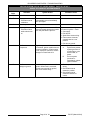
GRA SERIES GAS FRYERS - TROUBLESHOOTING
KLEENSCREEN FILTERING
SYSTEM
SYMPTOM
POSSIBLE CAUSES
Shortening not filtering, pump motor is
energized.
1. Filter screen plugged.
2. Clog in filter system lines.
NOTE: If using solid shortening, when all filtered shortening
is returned to the fry tank and filter power switch is off, open
the filter drawer approximately one inch. Allow the remaining
shortening in the line to drain into the filter tank to prevent
possible clogging after the shortening cools and solidifies.
Close the filter drawer when complete.
3. Shortening below 300°F to thick.
4. R2 fill relay N.C. contacts are open.
5. Fill solenoid valve malfunction.
6. Interconnecting wiring malfunction.
7. Pump is inoperative.
Shortening not discarding, pump motor
energized.
1. Filter screen plugged.
2. Clog in filter system lines.
NOTE: If using solid shortening, when all filtered shortening
is returned to the fry tank and filter power switch is off, open
the filter drawer approximately one inch. Allow the remaining
shortening in the line to drain into the filter tank to prevent
possible clogging after the shortening cools and solidifies.
Close the filter drawer when complete.
3. Shortening below 300°F to thick.
4. Discard valve switch malfunction (N.O. contacts not
closing to energize R2 fill relay coil).
5. R2 fill relay malfunction (contacts remain closed).
NOTE: The fill solenoid valve should not be energized
during discard operation so that shortening will flow thru
manual discard valve only.
6. Discard valve mechanical malfunction.
7. Discard hose connection not fully engaged.
8. Pump is inoperative.
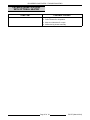
Pump motor is not energized to circulate
shortening thru filtering system.
1.
2.
3.
4.
5.
6.
Filter switch on cooking controls not turned on.
Pump needs reset. (Reset button located on pump)
R1 pump motor relay malfunction.
Cooking control malfunction.
Interconnecting wiring malfunction.
Pump motor inoperative.
Pump motor is not energized to discard
shortening.
1.
2.
3.
4.
5.
6.
7.
Filter switch on cooking controls not turned on.
Pump needs reset. (Reset button located on pump)
Discard handle (yellow) not extended.
R1 pump motor relay malfunction.
Cooking control malfunction.
Interconnecting wiring malfunction.
Pump motor inoperative.
F25377 (March 2010)
Printed in U.S.A.