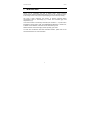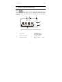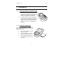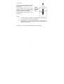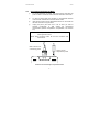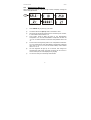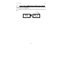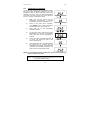
1
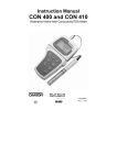
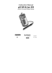
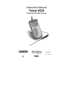
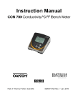
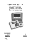
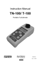
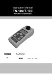
Instruction Manual Salt 6 Hand-held Salinity Meter 68X243619 Technology Made Easy ... ver. 0 051102 Preface This manual serves to explain the use of the Salt 6 salinity meter. It functions in two ways: first as a step by step guide to help you operate the meter; second, it serves as a handy reference guide. This manual is written to cover as many anticipated applications of the Salt 6 salinity meter as possible. If there are doubts in the use of this meter, please do not hesitate to contact the nearest Eutech Instruments/ Oakton Instruments Authorized Distributor. Eutech Instruments/ Oakton Instruments will not accept any responsibility for damage or malfunction to the meter caused by improper use of the instrument. The information presented in this manual is subjected to change without notice as improvements are made, and does not represent a commitment on the part of Eutech Instruments Pte Ltd/ Oakton Instruments. Copyright © 2002 Eutech Instruments Pte Ltd/ Oakton Instruments All rights reserved. Version 0, 051102. TABLE OF CONTENTS 1 2 3 4 5 6 INTRODUCTION 1 DISPLAY & KEYPAD FUNCTIONS 2.1 Display 2.2 Keypad 3 4 3 PREPARATION 3.1 Inserting & Removing Rubber Boot 3.2 Inserting the Batteries 3.3 Battery Replacement 3.4 Conductivity Electrode Information 3.5 Connecting the Probe to Meter 3.6 Switching the Meter On 3.7 Change Salinity ÙTemperature Measurement Mode 5 5 6 6 8 9 10 CALIBRATION 4.1 Important Information on Meter Calibration 4.2 Preparing the Meter for Calibration 4.3 Calibration for Salinity (% or ppt) 4.4 Temperature Calibration 11 12 13 14 MEASUREMENT 5.1 With Automatic Temperature Compensation (ATC) 5.2 Without ATC (Manual Temperature Compensation) 5.3 Taking Measurements 5.4 HOLD Function 15 16 17 18 ADVANCED SETUP FUNCTIONS 6.1 Advanced Setup Overview 6.2 Temperature Coefficient 6.3 Normalization Temperature 6.4 Selection of ppt or PrSn. (Default being PrSn) 6.5 Restore Factory Default Values 19 21 22 23 24 5 11 15 19 7 PROBE CARE AND MAINTENANCE 25 8 TROUBLE-SHOOTING GUIDE 26 9 ERROR MESSAGES 27 10 SPECIFICATIONS 29 11 ACCESSORIES 30 12 ADDENDUM 1: CALIBRATION TIPS 31 13 WARRANTY 32 14 RETURN OF ITEMS 33 Instruction Manual 1 Salt 6 INTRODUCTION Thank you for purchasing the Salt 6 Salinity meter. These economy microprocessor-based handheld meters deliver up to ±0.5% full-scale accuracy. It has a large custom LCD (Liquid Crystal Display) for clear and easy reading. The Salt 6 meter measures the amount of Sodium Chloride (NaCl) concentration either in Percentage (%) or Parts Per Thousand (ppt), and Temperature (°C). Your meter includes a conductivity electrode (cell constant K = 1.0) with built-in temperature sensor (Order Code: EC-CONSEN91B/ 35606-55), a rubber boot, 4 alkaline “AAA” batteries, instruction manual and warranty card. Please read this manual thoroughly before operating your meter. To order other accessories and buffer standard solutions, please refer to the Accessories Section for more information. 1 Instruction Manual Salt 6 Salt 6 % Salinity Meter ON OFF HOLD ENTER CAL MODE 2 Instruction Manual 2 2.1 Salt 6 DISPLAY & KEYPAD FUNCTIONS Display The meter has a large custom LCD that consists of 4-digit segments and operation annunciators for ppt or %, and °C (Temperature). Other annunciators include “HO” (when the HOLD function is activated) and “LO” (low battery condition). 6 4 5 % HO LO °C 3 ppt 2 1 LCD and Customized Annunciators for Salt 6 salinity meter 1. Primary display 4. Percentage indicator for Concentration and Temperature Coefficient. 2. Parts Per Thousand (ppt) 5. Low battery indicator. 3. Temperature indicator 6. Hold (freezed) indicator. 3 reading Instruction Manual 2.2 Salt 6 Keypad The Salt 6 salinity meter has 6 keys on its splash-proof keypad; ON/OFF, HOLD/ENTER CAL, MODE, ▲ and ▼ keys. Some buttons have several functions depending on its mode of operation. ON OFF CAL HOLD ENTER • Powers on and shuts off the meter. Takes you directly into measurement mode when meter is switched on. • Enters into calibration mode for % (or ppt) and Temperature. • To abort calibration or setup mode without confirming any set value. HOLD: Freezes the measured reading. To activate, press HOLD key while in measurement mode. To release, press HOLD key again. ENTER: Press to confirm values in calibration mode, and to confirm selections in SETUP mode. MODE • In Calibration Mode: Press to scroll through calibration values. • In Setup Mode: Press to scroll through the setup sub-group programmes. • Selects measurement mode for salinity and Temperature. • When pressed together with ON/OFF key, it will take you into the SETUP mode. This allows you to customize meter preferences such as selecting electrode’s normalization temperature, temperature coefficient factor, and resetting the meter to factory default. 1) Normalization Temperature 2) Temperature Coefficient Factor 3) Selection of ppt or % measurement mode (ppt or PrSn 4) User reset 4 Instruction Manual 3 Salt 6 PREPARATION 3.1 Inserting & Removing Rubber Boot 1) To remove meter from rubber boot, push out from the bottom edges of meter until it is completely out of boot. Ensure that the cables of Conductivity electrode or temperature probe are not connected. 2) To insert meter into rubber boot, slide in from the top of meter before pushing the bottom edges of meter down to set it into position. Lift up the stand at the back of meter for bench top applications if necessary. 3.2 Inserting the Batteries The battery compartment is found at the back of instrument as shown. To open the battery compartment: 3) Push in the direction of arrow and lift up the cover. 4) Note the polarity of battery before inserting into position. 5) After replacement, place cover back and press down until it locks tight. 5 Instruction Manual 3.3 Salt 6 Battery Replacement A “LO” annunciator in the LCD alerts you when battery power is running low. Replace with the same type as recommended by the manufacturer. LO % "LO" Battery Condition Caution: Power off the meter when changing battery. 3.4 Conductivity Electrode Information The Salt 6 salinity hand-held meter is supplied with a electrode with a BNC connector. This electrode (Order Part Number: EC-CONSEN91B/ 35606-55) comes with Stainless Steel rings, cell constant of K = 1.0, and a builtin temperature sensor for Automatic Temperature Compensation (ATC). Its specially designed Ultem-body housing has good chemical resistant properties. It provides fast temperature response and reduces air entrapment, which makes it easy to obtain accurate, stable readings. The probe materials used which have good chemical durability include: 1. Polyetherimide (Ultem) – protective probe guard 2. Polybutylterphalate (Valox) – sensor housing 3. Stainless Steel (SS 304) – 2 steel bands 6 Instruction Manual Salt 6 Proper use of probe is essential to ensure that the optimum measurement is taken in a short time. The removable protective plastic probe guard is meant for simple periodic maintenance and it must be kept in tact during measurement and calibration. Always immerse the probe beyond upper steel band. NOTE: 1) DO NOT remove the protective probe guard during measurement and calibration as it may affect your readings. 2) We recommend that you do not submerge the probe above the protective guard. You can submerge the cable for brief periods of time, but not continuously. See Section 7 - Probe Care and Maintenance” for more information. 7 Instruction Manual 3.5 Salt 6 Connecting the Probe to Meter 1) To connect electrode into meter, align the connector slots with the posts of meter’s socket and rotate connector clockwise until it locks. 2) To remove, simply rotate the connector in anti-clockwise direction until it unlocks, and slide the connector off the socket. 3) Insert the mini phono jack of temperature sensor into the socket on the meter as shown in Figure below. 4) Unplug the phono jack when not in use or when you want to measure Conductivity or TDS without any temperature compensation (Manual Temperature Compensation, see Section 5.2). CAUTION: Do not pull or force on the probe cord or the probe wires might disconnect. NOTE: Keep connectors clean. Do not touch connector with soiled hands. BNC connector for conductivity probe Phono jack for Temperature probe Connection for Conductivity & Temperature Probes 8 Instruction Manual 3.6 Salt 6 Switching the Meter On When switching the meter on, it will go through a series of displays, showing the various setup parameters. % °C ON OFF ppt JKT HO LO MAX MIN pH % % °C ° F m µS pptmV Measurement Mode (when probe is held in air) 1) Press ON/OFF key to power up your meter. 2) The first screen shows [SAL 6] which is the meter’s name. 3) Second screen shows [C 1.0] which is the conductivity cell constant, k. Cell constant value is fixed, k=1.0. 4) Third screen shows [t 25.0 °C] which is the Normalization Temperature. You can set Normalization Temperature at either 25 °C or 20 °C. Refer to Section on Advance Setup. Default value is 25 °C. 5) Fourth screen shows [t 2.1%] which is the Temperature Coefficient. You can customize the meter with different Temperature Coefficient value from 0.0 to 3.0 %/°C from the Advance Setup mode. Default value is 2.1 %/°C. 6) All LCD segments will light up for 2 seconds, and change into measurement mode. When the probe is held in the air and not in contact with liquid, the value displayed may be [Ur]. 7) You are now ready for conductivity measurement. 9 Instruction Manual 3.7 Salt 6 Change Salinity ÙTemperature Measurement Mode To switch between Salinity measurement mode and Temperature measurement mode, simply press the MODE key. The customized annunciator helps indicate the measurement parameter you are in. Annunciator °C ppt MODE 10 Instruction Manual 4 4.1 Salt 6 CALIBRATION Important Information on Meter Calibration The Salt 6 meter has a special built-in algorithm to linearize for the measurement of Sodium Chloride concentration. Therefore the specified accuracies from a One-point calibration anywhere in the measurement range, specified accuracies can be applied for the entire measurement range. When you recalibrate your meter, the old calibration will be replaced by the new calibration point. For example, if you previously calibrated your conductivity meter at 2.5% and you recalibrate at 1.0, the meter will replace the old calibration data (2.5%). To completely recalibrate your meter, or when you use a replacement probe, it is best to clear all calibration data. To erase all calibration data completely, see Section 6.5 – Restore Factory Default Values. 11 Instruction Manual 4.2 Salt 6 Preparing the Meter for Calibration Before starting calibration, make sure you are in the correct measurement mode. Ensure that you use new Sodium Chloride standard solutions during calibration. Do not reuse standard solutions as it may be contaminated and affect the calibration and accuracy of measurements. Use fresh calibration solution each time you calibrate your meter. Store solutions in a dry and cool environment if possible. Always rinse the probe with either deionized water or rinse solution before and after each calibration/sample measurement to avoid cross-contamination. For details please refer to Section 7 - Probe Care and Maintenance. NOTE: These meters are factory set to a temperature coefficient of 2.1% per °C. The factory default value for normalization temperature is 25 °C. If you need to normalize to a value other than 25 °C, see Section 6.3 – Normalization Temperature. 12 Instruction Manual 4.3 Salt 6 Calibration for Salinity (% or ppt) The following example shows calibration sequence to 2.5% calibration standard. Procedure is similar for both % and ppt measurement mode. 1) If necessary, press MODE key to select temperature mode. 2) Rinse the probe thoroughly with de-ionized water or a rinse solution, then rinse with a small amount of calibration standard. 3) Dip the probe into the calibration standard. Immerse the probe tip beyond the upper steel band (see Section 3.4). Stir the probe gently to create a homogeneous sample. Allow time for the reading to stabilize. 4) Measurement Mode % CAL % Press CAL key to enter salinity calibration mode. The [CA] indicator will appear for 1.5 seconds, and a value will appear flashing. NOTE: To exit calibration without confirmation, press CAL key again to go back to measurement mode. 5) Wait for the value to stabilize and press ▲ or ▼ key and adjust the value to the calibration standard used. 6) Press the ENTER key. The [CO] indicator will appear for 1.5 seconds, and the calibration is successfully performed. The meter returns to measurement mode. 13 % HOLD ENTER % Instruction Manual 4.4 Salt 6 Temperature Calibration The Conductivity electrode (EC-CONSEN91B/ 3560655) has a built-in temperature sensor for ATC. The temperature sensor is factory calibrated to the meter. Calibrate your sensor only if you suspect temperature errors that may have occurred over a long period of time or if you have a replacement probe. 1) Make sure that the phono jack (for temperature measurement) is properly connected to the meter. See Section 3.5. 2) Switch on the meter and if necessary, press MODE key to select temperature measurement mode. See Section 3.7. 3) Press CAL key to start temperature calibration process. 4) Dip the probe into a solution with known temperature (for example, a temperature bath). Allow time for the temperature to stabilize. 5) Wait for the value to stabilize and press ▲ or ▼ key and adjust the value to the solution temperature. 6) Press the ENTER key. The [CO] indicator will appear for 1.5 seconds, and the reading will stop flashing. The temperature calibration is successfully performed. The meter returns to measurement mode. °C CAL °C °C HOLD ENTER °C NOTE: To exit calibration without confirmation, press CAL key again to go back to measurement mode. NOTE: You can offset the temperature reading up to ±5 °C from the original (default) reading. 14 Instruction Manual 5 Salt 6 MEASUREMENT The Salt 6 meter is capable of taking measurements with automatic or manual temperature compensation. 5.1 With Automatic Temperature Compensation (ATC) For ATC, make sure the phono jack of the probe (see Section 3.5) is securely inserted. The % or ppt reading displayed will be compensated for according to the normalization temperature (20 °C or 25 °C) selected. See Section 6.3 – Normalization Temperature. 15 Instruction Manual 5.2 Salt 6 Without ATC (Manual Temperature Compensation) For manual temperature compensation, simply unplug the probe’s phono jack (not BNC) from the meter. To use manual temperature compensation, you need to enter the temperature value of your process into the meter. This is the value at which the reading will manually temperature compensates. You can select any temperature between 0 and 50 °C. Default value is 25 °C. 1) Make sure that the phono jack (for temperature measurement) is disconnected from the meter. See Section 3.5. 2) Switch on the meter and if necessary, press MODE key to select temperature measurement mode. See Section 3.7. 3) Press CAL key to calibration process. 4) The “CA” will appear momentarily and a temperature value will starting flashing. °C 5) Check the temperature of your sample using an accurate thermometer. Wait for the value to stabilize and press ▲ or ▼ key and adjust the value to the reference thermometer used. °C 6) start °C CAL temperature Press the ENTER key. The [CO] indicator will appear for 1.5 seconds, and the reading will stop flashing. The temperature calibration is successfully performed. The meter returns to measurement mode. HOLD ENTER °C 16 Instruction Manual 5.3 Salt 6 Taking Measurements To take readings: 1) Rinse the probe with de-ionized or distilled water before use to remove any impurities adhering to the probe body. Shake or air dry. To avoid contamination or dilution of your sample, rinse probe with a small volume of your sample liquid. 2) Press ON to switch on meter. 3) Dip the probe into the sample. 4) Allow time for the reading to stabilize. Note the reading on the display. NOTE: When dipping the probe into the sample, take care to ensure that the liquid level is above its upper steel band. Stir the probe gently in the sample to create a homogenous sample. See Figure in Section 3.4. 17 Instruction Manual 5.4 Salt 6 HOLD Function This feature lets you freeze the display for a delayed observation. HOLD can be used any time in measurement mode. 1) 2) To hold a measurement, press the HOLD key while in measurement mode. [HO] will appear on the display. % HOLD ENTER HO To release the held value, press the HOLD again. Continue to take measurements. NOTE: This meter shuts off automatically after 20 minutes of non usage. If the meter is shut off either automatically or manually, the HOLD value will be lost. 18 % Instruction Manual 6 Salt 6 ADVANCED SETUP FUNCTIONS 6.1 Advanced Setup Overview The advanced setup mode lets you customize your meter’s preferences and defaults. To enter advanced setup mode: 1) Make sure that the meter is switched-off. 2) Press ON and MODE key simultaneously, holding both keys for 2 seconds. First release ON key first before releasing the MODE key. 3) [StUP] indicator will appear momentarily and [tCo%] will appear next. Enter Setup Page. % Adjust Temperature Coefficient value from 0.0 to 3.0 %/°C. Default value is 2.1 %/°C. °C Select Normalization Temperature. Choice of either 20 °C or 25 °C. Default value is 25 °C. To choose measurement parameter, TDS (ppt) or percentage (%). User re-set to factory defaults. Choice of “Yes” or “No”. Default value is “no”. 19 Instruction Manual Salt 6 Meter Off ON OFF MODE Press ON/OFF and MODE keys simultaneously for 2 seconds, release ON/OFF key first then release MODE key a second later. A "StUP" indicator will appear for 1.5 seconds before showing the first menu % °C Overview of Salt 6 Setup Menu 20 Instruction Manual 6.2 Salt 6 Temperature Coefficient The temperature coefficient is the amount of change in conductivity per degree of temperature; it is expressed in percent per °C. Entering the exact temperature coefficient of your solution lets you accurately compensate temperature for almost any solution. You can adjust 0.0 to 3.0 % per °C. Meter default is 2.1% per °C. 1) Enter the advanced setup as described in Section 6.1. 2) Press ▲ or ▼ key until [t.Co %] appears on the LCD. Press ENTER key. 3) Press ▲ or ▼ key to select a value between 0.0 to 3.0. 4) Press ENTER key to select. The meter will take you back to the menu, [t.Co %]. 5) Press ▲ or ▼ key to move to the next menu or press CAL to exit to measurement mode. 21 % HOLD ENTER % % Instruction Manual 6.3 Salt 6 Normalization Temperature You can set the meter to normalize its conductivity measurements to a standard temperature of either 25 °C or 20 °C. The default value is 25 °C. 1) Enter the advanced setup as described in Section 6.1. 2) Press ▲ or ▼ key until [t.nr °C] appears on the LCD. Press ENTER key. 3) Press ▲ or ▼ key to select either [25.0 °C] or [20.0 °C]. 4) Press ENTER key to select. The meter will take you back to the menu, [t.nr °C]. 5) Press ▲ or ▼ key to move to the next menu or press CAL to exit to measurement mode. 22 °C HOLD ENTER °C °C Instruction Manual 6.4 Salt 6 Selection of ppt or PrSn. (Default being PrSn) Choose to have your measurement reading in ppt or percentage (PrSn). 1) Enter the advanced setup described in Section 6.1. as 2) Press ▲ or ▼ key until [SAlt] appears on the LCD. Press ENTER key. 3) Press ▲ or ▼ key to select either [PrSn] or [PPt]. 4) Press ENTER key to select. The meter will take you back to the menu, [SAlt]. 5) Press ▲ or ▼ key to move to the next menu or press CAL to exit to measurement mode. HOLD ENTER HOLD ENTER CAL 23 Instruction Manual 6.5 Salt 6 Restore Factory Default Values This function allows you to reset all parameters to factory default settings. This clears all calibration data and any other setup functions you might have changed. IMPORTANT: Once activated the meter’s settings and calibration data will be erased and always exercise caution as meter reset is not reversible. 1) Enter the advanced setup as described in Section 6.1. 2) Press ▲ or ▼ key until [UrSt] appears on the LCD. Press ENTER key. 3) Press ▲ or ▼ key to select either [Yes] or [no]. 4) Press ENTER key to select. 5) The meter will go back to measurement mode after the switch-on initialization as shown in figure of Section 3.6. 24 HOLD ENTER Instruction Manual 7 Salt 6 PROBE CARE AND MAINTENANCE Keep the conductivity probe clean. Rinse the probe twice, and gently swirl it while you take readings. For best accuracy, soak a dry probe for at least 5 to 10 minutes or longer before calibration. Rinse the probe with deionized water before storing. Never scratch the bands with a hard substance. Do not strike the probe against any hard surface. Do not make continuous contact with your solutions. Readings will rise over a period of time while you soak your probe. Do not immerse the probe in oily solutions. Clean the electrode thoroughly by stirring it in a mild detergent bath or isopropyl alcohol. Wipe the probe with soft tissue paper. Rinse thoroughly in tap water and then in deionized water. Recalibrate the meter after cleaning the probe. The conductivity probe (Order Part No. ECCONSEN91B/ 35606-55) which is included with your meter features a removable probe guard to make cleaning easy. To remove probe guard: 1) Grip yellow probe guard and twist clockwise. The locking notch will release. 2) Slide probe guard off end of probe. NOTE: Remember to re-attach the probe guard prior to taking readings. Failure to do so could result in erroneous readings. 25 Instruction Manual 8 Salt 6 TROUBLE-SHOOTING GUIDE Problem Cause Solution Power on but no display a) Batteries not in place a) Check that batteries are in place and making good contact. b) Batteries not in correct polarity (+ and – position). Unstable readings c) Weak batteries c) Replace batteries. a) Air bubbles in probe. a) Tap probe to remove bubbles. b) Dirty probe. b) Clean the probe and re-calibrate. c) Probe not deep enough in sample. c) Make sure sample entirely covers the probe sensors. d) Move or switch off interfering motor. e) Broken probe. e) Replace probe. a) Dirty / Oily probe. a) Clean probe. See “Probe Care & Maintenance”. d) External noise pickup or induction caused by nearby electric motor. Slow response b) Re-insert batteries with correct polarity. 26 Instruction Manual 9 Salt 6 ERROR MESSAGES LCD Display Indicates Cause Solution “LO” indicator appears. Low battery level. Need new batteries or battery connection is bad. Clean battery contacts. Replace batteries with fresh ones, noting polarity. Err 1 Salinity calibration error The cal key is pressed during Ur or Or. The value of the solution is out of the 1- 50 ppt range. Make sure that the probe is immersed into the salt solution which is in the range of interest. Err. 2 Temperature calibration error. Auto calibration is performed outside the temperature range (0 – 50 °C). Check the temperature and make sure that it is within the acceptable range. If message persists, return unit*. * See Sections on “Warranty” and “Return of Items”. 27 Instruction Manual Salt 6 If an error message appears, switching off the meter and switching it on again may eliminate the error message. If error persists, or the meter shows incorrect values, return the meter. For a complete diagram of the display see page 3. See sections on “Warranty” and “Return of items”. 28 LO µS Instruction Manual 10 Salt 6 SPECIFICATIONS SPECIFICATIONS DESCRIPTIONS Percentage (%) Range 0.10 to 5.00 % Resolution 0.01 % Accuracy ±1% F.S. TDS Range 1.0 to 50.0 ppt Resolution 0.1 ppt Accuracy ±1% F.S. -10.0 to 110.0 °C Temperature Range 0.1 °C / ± 0.5 for °C Resolution/Accuracy Cell Constant Temperature Compensation 1.0 Automatic / Manual (from 0 to 50 °C) Temperature Coefficient 0.0 to 3.0% / °C Normalization Temperature Saline Conversion Factor 20.0 °C and 25.0 °C (selectable) Non-linear Compensation Number of calibration points 1 point HOLD Function Yes Auto Power off 20 minutes after last key operation Inputs BNC for conductivity and phono jack for temperature Display Single Custom LCD Power Requirements 4 ‘AAA’ Batteries Battery Life > 100 hours Dimension / Weight Meter: 14 x 7 x 3.5 cm; 200 g 29 Instruction Manual 11 Salt 6 ACCESSORIES Replacement Meter and Meter accessories Item Eutech Instruments Oakton Instruments Ordering Code Ordering Code Salt 6 portable salinity meter complete with conductivity probe of k=1.0 (CONSEN91B). ECSALT603K 35606-20 3 ring SS, Ultem body Electrode with ATC & BNC plug (for CON 6), cell constant = 1.0, x110 mm, 1m cable length ECCONSEN91B 35606-55 Carrying kit with calibration standards and rinse bottle. ECECOCONKIT 35632-97 Calibration Solutions Item Item Eutech Instruments Oakton Instruments Ordering Code Ordering Code 5 ppt (0.5%) Sodium Chloride (NaCl) Calibration Solution in 480-ml leak-proof bottle. ECNACL5PPT 4.487 ppt Sodium Chloride (NaCl) Calibration Solution in 500-ml leak-proof bottle. 00653-89 25 ppt (2.5%) Sodium Chloride (NaCl) Calibration Solution in 480-ml leak-proof bottle. ECNACL25PPT 8.532 ppt Sodium Chloride (NaCl) Calibration Solution in 500-ml leak-proof bottle. 00653-50 45 ppt (4%) Sodium Chloride (NaCl) Calibration Solution in 480-ml leak-proof bottle. ECNACL45PPT 48.384 Sodium Chloride (NaCl) Calibration Solution in 500-ml leakproof bottle. 00653-32 30 Instruction Manual 12 Salt 6 ADDENDUM 1: CALIBRATION TIPS You only need one calibration for measurement throughout the entire range of the meter. Wet the probe for 10 minutes before calibrating or taking readings to saturate the probe surface and minimize drift. If you make measurements at extreme temperatures, calibrate the meter at least once a week. You should only use the conductivity probe specified for this meter. These probes have a built-in temperature sensor. If you use a different probe without a temperature sensor, you must measure the solution temperature separately and manually enter the solution temperature. 31 Instruction Manual 13 Salt 6 WARRANTY This meter is supplied with a warranty against significant deviations in material and workmanship for a period of THREE years from date of purchase whereas probe with a SIX-month warranty. If repair or adjustment is necessary and has not been the result of abuse or misuse within the designated period, please return – freight pre-paid – and correction will be made without charge. Eutech Instruments/ Oakton Instruments will determine if the product problem is due to deviations or customer misuse. Out of warranty products will be repaired on a charged basis. Exclusions The warranty on your instrument shall not apply to defects resulting from: Improper or inadequate maintenance by customer Unauthorized modification or misuse Operation outside of the environment specifications of the products 32 Instruction Manual 14 Salt 6 RETURN OF ITEMS Authorization must be obtained from our Customer Service Department or authorized distributor before returning items for any reason. A “Return Goods Authorization” (RGA) form is available through our authorized distributor. Please include data regarding the reason the items are to be returned. For your protection, items must be carefully packed to prevent damage in shipment and insured against possible damage or loss. Eutech Instruments/ Oakton Instruments will not be responsible for damage resulting from careless or insufficient packing. A restocking charge will be made on all unauthorized returns. NOTE: Eutech Instruments Pte Ltd/ Oakton Instruments reserves the right to make improvements in design, construction, and appearance of products without notice. 33 NOTES For more information on Eutech Instruments/ Oakton Instruments’ products, contact your nearest distributor or visit our website listed below: Oakton Instruments P.O Box 5136, Vernon Hills, IL60061, USA Fax: (1) 847-247-2984 www.4oakton.com www.oaktoninstruments.com Eutech Instruments Pte Ltd. Blk 55, Ayer Rajah Crescent, #04-16/24 Singapore 139949 Tel: (65) 6778 6876 Fax: (65) 6773 0836 E-mail: [email protected] Web-site: www.eutechinst.com Distributed by: