1
iR1600/iR2000/
iR1610/iR2010
SERIES
REVISION 0
MAR. 2002
COPYRIGHT© 2002 CANON INC.
FY8-13HS-000
CANON iR1600/iR2000/iR1610/iR2010 SERIES REV.0 MAR. 2002 PRINTED IN JAPAN (IMPRIME AU JAPON)
Application
This manual has been issued by Canon Inc. for qualified persons to learn technical
theory, installation, maintenance, and repair of products. This manual covers all localities
where the products are sold. For this reason, there may be information in this manual
that does not apply to your locality.
Corrections
This manual may contain technical inaccuracies or typographical errors due to
improvements or changes in products. When changes occur in applicable products or in
the contents of this manual, Canon will release technical information as the need arises.
In the event of major changes in the contents of this manual over a long or short period,
Canon will issue a new edition of this manual.
The following paragraph does not apply to any countries where such provisions are
inconsistent with local law.
Trademarks
The product names and company names used in this manual are the registered
trademarks of the individual companies.
Copyright
This manual is copyrighted with all rights reserved. Under the copyright laws, this
manual may not be copied, reproduced or translated into another language, in whole or in
part, without the written consent of Canon Inc.
COPYRIGHT © 2002 CANON INC.
Printed in Japan
Imprimé au Japon
Caution
Use of this manual should be strictly supervised to avoid disclosure of confidential information.
COPYRIGHT© 2002 CANON INC.
CANON iR1600/iR2000/iR1610/iR2010 SERIES REV.0 MAR. 2002 PRINTED IN JAPAN (IMPRIME AU JAPON)
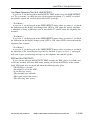
INTRODUCTION
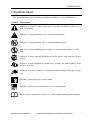
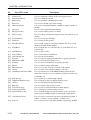
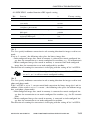
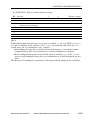
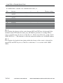
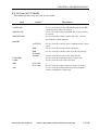
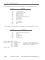
1 Symbols Used
This documentation uses the following symbols to indicate special information:
Symbol
Description
Indicates an item of a non-specific nature, possibly classified as Note, Caution, or Warning.
Indicates an item requiring care to avoid electric shocks.
Indicates an item requiring care to avoid combustion (fire).
Indicates an item prohibiting disassembly to avoid electric shocks or problems.
Indicates an item requiring disconnection of the power plug from the electric
outlet.
Memo
REF.
Indicates an item intended to provide notes assisting the understanding of the
topic in question.
Indicates an item of reference assisting the understanding of the topic in question.
Provides a description of a service mode.
Provides a description of the nature of an error indication.
Refers to the Copier Basics Series for a better understanding of the contents.
COPYRIGHT © 2002 CANON INC. 2001 2001 CANON iR1600/iR2000/iR1610/iR2010 SERIES REV.0 MAR. 2002
i
INTRODUCTION
2 Outline of the Manual
This Service Manual provides basic facts and figures needed to service the iR1600/
iR2000. Of the machine’s accessories, this manual covers the cassette unit and inner 2way tray; for other accessories including the ADF, see its own Service Manual.
In this manual, the 1-Cassette Unit-F1, 2-Cassette Unit-G1 and 3-Cassette Unit-H1 are
collectively called “cassette unit,” and the Inner 2-Way Tray-B1 is referred to as the inner
2-way tray.
This Service Manual consists of the following chapters:
Chapter 1 Introduction:
Chapter 2 Basic Operation:
features, specifications, operation, system construction, routine maintenance by the user, safety,
reproduction processes
basic operation, outline of electrical circuitry, basic sequence
Chapter 3 Image Reading/
Processing System:
principles of operation of the exposure system,
principles of operation of the image processing
system, timing of operation; disassembly/assembly
and adjustment
Chapter 4 Laser Exposure System: principles of operation of the image formation system, timing of operation; disassembly/assembly
Chapter 5 Image formation system: standards, adjustments, troubleshooting tables
Chapter 6 Pickup/Feeding System: principles of operation of the pickup/feeding system, timing of operation; disassembly/assembly
and adjustment
Chapter 7 Fixing System:
principles of operation of the fixing system, timing
of operation; disassembly/assembly and adjustment
Chapter 8 Externals and Auxiliary
Control System:
principles of operation of the externals/auxiliary
control system, timing of operation; disassembly/
assembly and adjustment
Chapter 9 Cassette Unit:
principles of operation of the pickup system; disassembly/assembly and adjustments
Chapter 10 Inner 2-Way Tray:
principles of operation; disassembly/assembly and
adjustment
Chapter 11 Installation:
site requirements and installation procedure
Chapter 12 Maintenance and
Inspection:
table of periodically replaced parts, table of
durables, scheduled servicing chart
Chapter 13 Troubleshooting:
maintenance and inspection, standards/adjustment,
troubleshooting image faults/malfunctions; service
mode, self diagnosis
Chapter 14 Version up:
version up
Appendix:
general timing chart, general circuit diagram
ii
COPYRIGHT © 2002 CANON INC. 2001 2001 CANON iR1600/iR2000/iR1610/iR2010 SERIES REV.0 MAR. 2002
INTRODUCTION
The descriptions are subject to change for product improvement, and major changes
will be communicated in the form of Service Information bulletins.
All service persons are expected to go through the contents of this Service Manual and
Service Information bulletins and have a good understanding of the machine, readying
themselves to promptly respond to the needs of the field (i.e., identifying and correcting
faults).
COPYRIGHT © 2002 CANON INC. 2001 2001 CANON iR1600/iR2000/iR1610/iR2010 SERIES REV.0 MAR. 2002
iii
INTRODUCTION
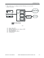
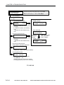
The descriptions in this Service Manual are based on he following rules:
1. In each chapter, the uses of the function in question and its relationship to electrical
and mechanical systems are discussed and the timing of operation of its associated
parts is explained by means of outlines and diagrams.
In the diagrams, the symbol
represents a mechanical path, while the symbol
with a name next to it indicates the flow of an electric signal.
The expression “turn on the power” means turning on the power switch, closing the
front door, and closing the delivery door so that the machine will be supplied with
power.
2. In circuit diagrams (digital), a signal whose level is High is expressed as being ‘1’,
while a single whose level is Low is expressed as being ‘0’; the level of voltage, however, varies from circuit to circuit.
The machine uses CPUs, whose internal mechanisms cannot be checked in the field,
and, therefore, are not explained. In addition, the machine’s PCBs are not intended for
repairs at the user’s and, therefore, are explained by means of block diagrams: two
types are used, i.e., between sensors and inputs of PCBs equipped with a control or
drive function and between outputs equipped with a control or drive function and
loads; in addition, functional block diagrams are used at times.
Changes made to the machine for product improvement are communicated in the form
of a Service Information bulletin as needed. All service persons are expected to go
through all service documentation including the bulletins and be equipped to respond to
the needs of the field (as by being able to identify possible causes of problems).
iv
COPYRIGHT © 2002 CANON INC. 2001 2001 CANON iR1600/iR2000/iR1610/iR2010 SERIES REV.0 MAR. 2002
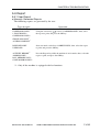
INTRODUCTION
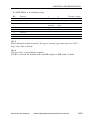
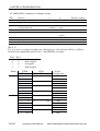
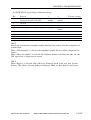
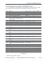
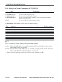
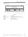
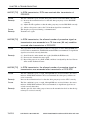
This service manual covers the models shown in the following table. Be sure to have a
good understanding of the difference from model to model before referring to this
manual.
Model
ADF
function
Fax
function
Printer
function
Cassette
Type
Copying speed
(cpm) at Direct
iR1600
*1
1-cassette
16cpm/LTR
iR2000
*1
2-cassette
20cpm/LTR
iR1610F
√
√
1-cassette
16cpm/LTR
iR2010F
√
√
2-cassette
20cpm/LTR
The notation “ √” indicates that the item in question is available.
*1 : Fax function not supported.
COPYRIGHT © 2002 CANON INC. 2001 2001 CANON iR1600/iR2000/iR1610/iR2010 SERIES REV.0 MAR. 2002
v
INTRODUCTION
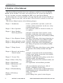
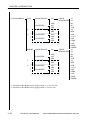
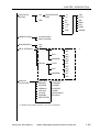
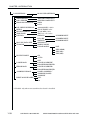
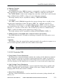
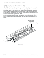
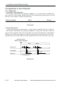
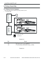
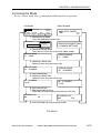
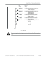
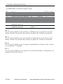
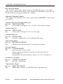
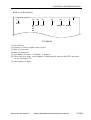
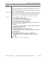
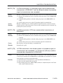
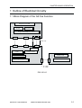
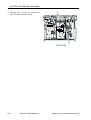
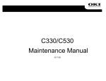
System Configuration
1. The machine may be configured as follows with its accessories (except the printer/fax
device):
[1]
[3]
[2]
[6]
[4]
[7]
[5]
F1
[1]
[2]
[3]
[4]
[5]
[6]
[7]
vi
F2
ADF-J1 (iR1600/iR2000 only)
Finisher-L1 (if PDL output, requires hard disk.)
Inner 2-Way Tray-B1
1-Cassette Unit-F1 (16cpm model only)
2-Cassette Unit-G1 (20cpm model only)
3-Cassette Unit-H1 (16cpm model only)
Card Reader-E1
COPYRIGHT © 2002 CANON INC. 2001 2001 CANON iR1600/iR2000/iR1610/iR2010 SERIES REV.0 MAR. 2002
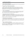
INTRODUCTION
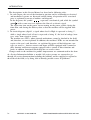
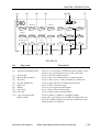
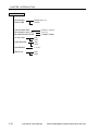
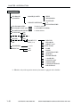
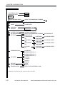
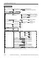
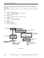
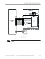
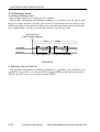
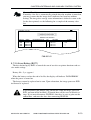
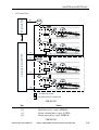
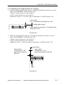
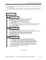
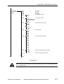
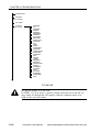
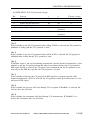
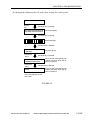
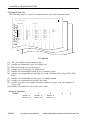
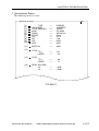
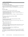
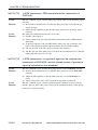
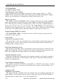
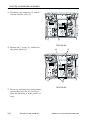
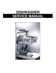
2. The machine may be configured with the following accessory boards:
• Printer accessories
Centronics interface
or USB interface
Hard
Disk
[3]
Printer
Board
[1]
Flash ROM
[4]
[4]
[2]
Ethernet
Board
LAN interface
PS Module
[5]
: Internal interface
: External interface
F3
[1]
[2]
[3]
[4]
[5]
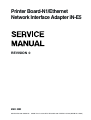
Printer Board-N1
Ethernet Network Interface Adapter iN-E5
Hard Disk HD-65
Flash ROM Module FR-65
PS Module-B1
COPYRIGHT © 2002 CANON INC. 2001 2001 CANON iR1600/iR2000/iR1610/iR2010 SERIES REV.0 MAR. 2002
vii
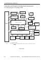
INTRODUCTION
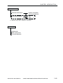
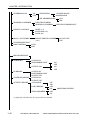
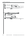
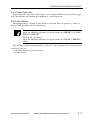
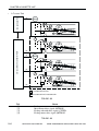
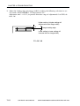
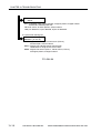
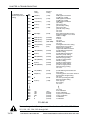
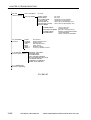
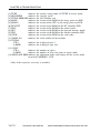
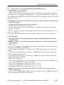
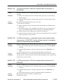
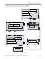
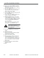
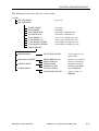
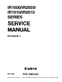
• Fax accessories (iR1610F/iR2010F only)
[1] G3 FAX BOARD
NCU PCB
Modular
PCB
[2] G3 FAX EXPANSION KIT-B1
NCU PCB
G3 multiport PCB
2-line
Modular
PCB
PSTN
: Internal interface
: External interface
F4
[1]
[2]
G3 FAX BAORD*1
G3 FAX EXPANSION KIT-B1*2
*1 : Standard (iR1610F/iR2010F)
*2 : iR1610F/iR2010F 120V only
viii
COPYRIGHT © 2002 CANON INC. 2001 2001 CANON iR1600/iR2000/iR1610/iR2010 SERIES REV.0 MAR. 2002
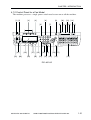
INTRODUCTION
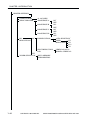
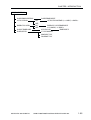
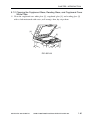
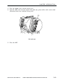
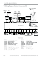
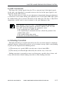
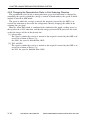
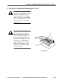
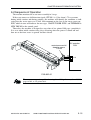
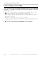
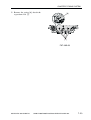
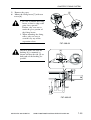
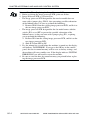
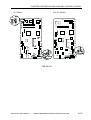
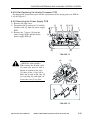
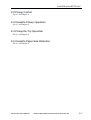
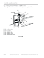
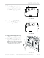
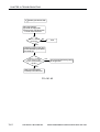
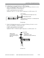
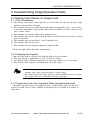
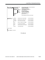
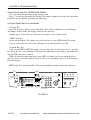
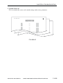
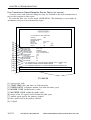
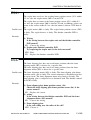
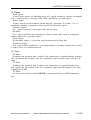
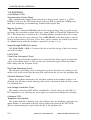
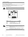
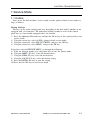
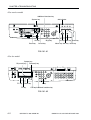
<Points to Note When Turning Off the Power Switch>
Be sure to turn off the power switch and disconnect the power plug before starting disassembly/assembly work; further, keep the following in mind:
1. If you turn off the main power switch while a printer function is in use, the data being
processed can be lost. Check to be sure that the online indicator in the control panel is
OFF before operating the power switch.
2. Do not turn off the power switch while downloading is taking place; otherwise, the
machine may fail to operate.
3. Remember that not all power will be removed in response to the opening of the front
cover as long as the power switch remains ON.
4. Be sure to use SHUT DOWN MENU to shut down the printer if the Hard Disk HD-65
(accessory) has been installed.
[2]
[2]
[1]
[1]
F5
[1]
[2]
Power switch
Online indicator
COPYRIGHT © 2002 CANON INC. 2001 2001 CANON iR1600/iR2000/iR1610/iR2010 SERIES REV.0 MAR. 2002
ix
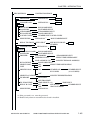
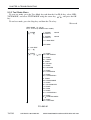
CONTENTS
Contents
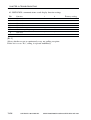
CHAPTER 1 INTRODUCTION
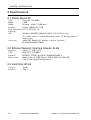
1 Features .............................................. 1-1
1.1 Features ...................................... 1-1
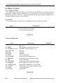
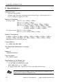
2 Specifications ..................................... 1-3
2.1 Copier ........................................ 1-3
2.1.1 Type ..................................... 1-3
2.1.2 System ................................. 1-3
2.1.3 Functions ............................. 1-4
2.1.4 Others .................................. 1-6
2.2 Cassette Unit ............................. 1-8
2.3 Inner 2-Way Tray ....................... 1-9
3 Names of Parts ................................. 1-10
3.1 External View .......................... 1-10
3.1.1 Copier ................................ 1-10
3.1.2 Cassette Unit ..................... 1-12
3.1.3 Inner 2-Way Tray .............. 1-13
3.2 Cross Section ........................... 1-14
3.2.1 Copier ................................ 1-14
3.2.2 Cassette Unit ..................... 1-16
3.2.3 Inner 2-Way Tray .............. 1-17
4 Control Panel .................................... 1-18
4.1 Control Panel ........................... 1-18
4.1.1 Control Panel for a
Non-Fax Model ................. 1-18
4.1.2 Control Panel for a
Fax Model ......................... 1-21
4.1.3 Master Password ............... 1-25
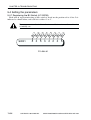
4.2 Basic Operation ....................... 1-26
4.2.1 Basic Operation for a
Non-Fax Model ................. 1-26
4.2.2
Basic Operation for
a Fax Model ....................... 1-26
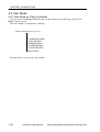
4.3 Extended Operation ................. 1-27
4.3.1 Extended Operation for a
Non-Fax Model ................. 1-27
4.3.2 Extended Operation for a
Fax Model ......................... 1-27
4.4 User Mode ............................... 1-28
4.4.1 User Mode for a
Non-Fax Model ................. 1-28
4.4.2 User Mode for a
Fax Model ......................... 1-36
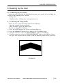
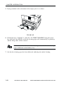
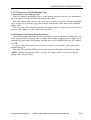
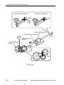
5 Cleaning by the User ........................ 1-59
5.1 Cleaning by the User ............... 1-59
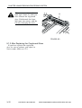
5.1.1 Cleaning the Fixing Roller 1-59
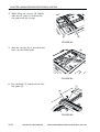
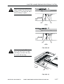
5.1.2 Cleaning the Copyboard Glass,
Reading Glass, and Copyboard
Cover White Plate ............ 1-61
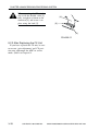
5.1.3 Cleaning the ADF Roller/
Guide Assembly ................ 1-62
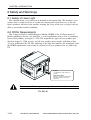
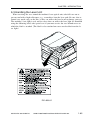
6 Safety and Warnings ........................ 1-64
6.1 Safety of Laser Light .............. 1-64
6.2 CDRH Requirements ............... 1-64
6.3 Handling the Laser Unit .......... 1-65
6.4 Safety of the Toner .................. 1-66
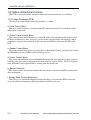
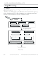
7 Reproduction Processes ................... 1-67
7.1 Outline ..................................... 1-67
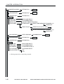
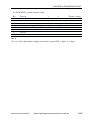
CHAPTER 2 BASIC OPERATION
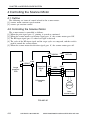
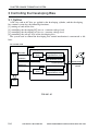
1 Basic Operation .................................. 2-1
1.1 Functional Construction ............ 2-1
1.2 Outline of Electrical Circuitry .. 2-2
1.2.1 Image Processor PCB ......... 2-2
1.2.2 DC Controller PCB ............. 2-3
1.2.3 Power Supply PCB .............. 2-5
x
1.2.4 Analog Processor PCB ........ 2-5
1.3 Inputs to and Outputs from
Electrical Components ................ 2-6
1.3.1 Wiring Diagram of the Major
PCBs .................................... 2-6
COPYRIGHT © 2002 CANON INC. 2001 2001 CANON iR1600/iR2000/iR1610/iR2010 SERIES REV.0 MAR. 2002
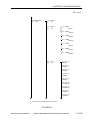
CONTENTS
1.3.2
Wiring Diagram of the Electrical
Components (1/2) ................ 2-7
1.3.3 Wiring Diagram of Electrical
Components (2/2) ................ 2-8
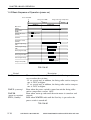
1.4 Basic Sequence of Operation .... 2-9
1.4.1 Outline ................................. 2-9
1.4.2 Basic Sequence of Operation
(power-on) ......................... 2-10
1.4.3
Basic Sequence of Operation
(printing) ........................... 2-11
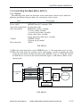
1.5 Controlling the Main Motor
(M101) ..................................... 2-13
1.5.1 Outline ............................... 2-13
CHAPTER 3 IMAGE READING/PROCESSING SYSTEM
1 Outline of Operation .......................... 3-1
1.1 Outline ....................................... 3-1
2 Reader Drive System ......................... 3-2
2.1 Outline ....................................... 3-2
2.2 Controlling the Reader Motor ... 3-3
2.2.1 Moving the Carriage in
Reverse After an
Image Scan .......................... 3-3
3 Detecting the Size of Originals ......... 3-4
3.1 Outline ....................................... 3-4
3.2 Detection by the
Original Size Sensors ................ 3-4
3.3 Detecting the Size of
Originals .................................... 3-6
3.4 Detection by the ADF ............... 3-7
4 Image Processing ............................... 3-8
4.1 Outline ....................................... 3-8
4.2 Contact Sensor ........................... 3-9
4.2.1 Outline of the Contact
Sensor .................................. 3-9
4.2.2 Construction of the Contact
Sensor (CS) ....................... 3-10
4.3 A/D Conversion ....................... 3-11
4.4 Shading Correction .................. 3-11
4.4.1 Black Shading
Correction .......................... 3-12
4.4.2 White Shading
Correction .......................... 3-12
4.5 Re-Ordering ............................. 3-12
4.6 ABC
(auto background control) ....... 3-13
4.7 LED Intensity Adjustment ...... 3-14
4.8 Enlargement/Reduction ........... 3-14
4.8.1 Enlargement/Reduction in
Main Scanning Direction .. 3-14
4.8.2 Changing the Reproduction
Ratio in Sub Scanning
Direction ............................ 3-16
4.9 Edge Emphasis ........................ 3-17
4.10 Editing ..................................... 3-17
4.11 Density Conversion (LUT, i.e.,
look-up table processing) ........ 3-17
4.11.1 Density Adjustment
(F-value conversion) ......... 3-17
4.11.2 Density Correction
(γ correction) ..................... 3-17
4.12 Binary Processing .................... 3-18
4.12.1 Error Diffusion .................. 3-18
4.13 Image Memory Control ........... 3-18
4.13.1 Compression/Expansion,
Rotation, and Enlargement/
Reduction .......................... 3-18
4.13.2 SDRAM ............................. 3-18
4.14 Output Image Processing ........ 3-19
4.14.1 Smoothing ......................... 3-19
5 Disassembly and Assembly ............. 3-20
5.1 Copyboard Glass ..................... 3-21
5.1.1 Removing the
Copyboard Glass ............... 3-21
5.1.2 After Replacing the
Copyboard Glass ............... 3-22
COPYRIGHT © 2002 CANON INC. 2001 2001 CANON iR1600/iR2000/iR1610/iR2010 SERIES REV.0 MAR. 2002
xi
CONTENTS
5.2 CS Unit .................................... 3-23
5.2.1 Removing the CS Unit ...... 3-23
5.2.2 Points to Note When
Mounting the CS Unit ....... 3-26
5.2.3 After Replacing the
CS Unit .............................. 3-28
5.2.4
Points to Note When
Handling the CS Unit ........ 3-29
5.3 Reader Motor ........................... 3-30
5.3.1 Removing the Reader
Motor ................................. 3-30
5.3.2 Points to Note When Mounting
the Reader Motor .............. 3-31
CHAPTER 4 LASER EXPOSURE SYSTEM
1 Outline of Operation .......................... 4-1
1.1 Outline ....................................... 4-1
1.2 Basic Sequence of Operation
(laser exposure system) ............. 4-3
2 Generating the Horizontal Signal ...... 4-4
2.1 Outline ....................................... 4-4
2.2 Signals Used .............................. 4-4
3 Laser Driver Circuit ........................... 4-6
3.1 Laser Control ............................. 4-6
4 Controlling the Scanner Motor .......... 4-8
4.1 Outline ....................................... 4-8
4.2 Controlling the Scanner
Motor ......................................... 4-8
4.3 Scanner Pre-Rotation ................ 4-9
5 Disassembly and Assembly ............. 4-10
5.1 Removing the Laser/
Scanner Unit ............................ 4-11
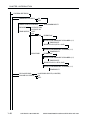
CHAPTER 5 IMAGE FORMATION SYSTEM
1 Outline of Processes ........................... 5-1
1.1 Sequence of Operation
(image formation system) ......... 5-3
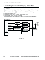
2 1 Controlling the Primary Charging
Roller Bias .......................................... 5-4
2.1 Outline ....................................... 5-4
2.2 Turning On and Off the Bias ..... 5-5
2.2.1 DC Bias ............................... 5-5
2.2.2 AC Bias ............................... 5-5
2.3 Bias Constant Voltage/
Constant Current Control .......... 5-5
2.3.1 DC Bias Constant Voltage
Control ................................. 5-5
2.3.2 AC Bias Constant Current
Control ................................. 5-5
3 Controlling the Developing Bias ....... 5-6
3.1 Outline ....................................... 5-6
3.2 Turning On/Off the Bias ........... 5-7
3.2.1 DC Bias ............................... 5-7
3.2.2 AC Bias ............................... 5-7
xii
3.3 Controlling the Bias to a
Constant Voltage Level .............. 5-7
3.3.1 Controlling the Developing
DC Bias to a Constant
Level .................................... 5-7
3.3.2 Controlling the Developing
AC Bias to a Constant
Voltage Level ....................... 5-7
3.4 Controlling the Voltage Level of
the Developing DC Bias ............ 5-7
4 Controlling the Transfer
Charging Roller Bias .......................... 5-8
4.1 Outline ....................................... 5-8
4.2 Turning On and Off the Bias ..... 5-9
4.2.1 Turning On and Off the
Positive DC Bias ................. 5-9
4.2.2 Turning On and Off the
Negative DC Bias ................ 5-9
4.3 Controlling the Bias to a Constant
Current /Voltage Level .............. 5-9
COPYRIGHT © 2002 CANON INC. 2001 2001 CANON iR1600/iR2000/iR1610/iR2010 SERIES REV.0 MAR. 2002
CONTENTS
4.3.1
Controlling the DC Bias to a
Constant Current Level ....... 5-9
4.3.2 Controlling the DC Bias to a
Constant Level .................... 5-9
4.4 Correcting the Voltage Level
(ATVC control) ........................ 5-10
4.5 Controlling the Output According
to Operation Mode .................. 5-10
4.5.1 Type of Mode .................... 5-10
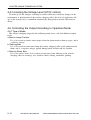
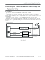
5 Detecting the Presence/Absence of a
Cartridge and the Level of Toner ..... 5-11
5.1 Outline ..................................... 5-11
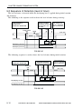
5.2 Sequence of Detection
(level of toner) ......................... 5-12
6 Monitoring the Waste Toner Case ... 5-14
6.1 Outline ..................................... 5-14
6.2 Sequence of Operation ............ 5-15
7 Disassembly and Assembly ............. 5-16
7.1 Photosensitive Drum ............... 5-17
7.1.1 Removing the Drum
Unit .................................... 5-17
7.1.2 Cleaning the
Photosensitive Drum ......... 5-17
7.2 Developing Assembly ............. 5-18
7.2.1 Removing the Developing
Assembly ........................... 5-18
7.3 Transfer Roller ........................ 5-20
7.3.1 Removing the Transfer
Roller ................................. 5-20
CHAPTER 6 PICKUP/FEEDING SYSTEM
1 Outline ................................................ 6-1
1.1 Specifications and
Constructions ............................. 6-1
1.2 Arrangement of
Major Rollers and Sensors ........ 6-2
2 Controlling the Pickup Assembly ...... 6-3
2.1 Controlling the Pickup
from the Cassette ....................... 6-3
2.1.1 Outline ................................. 6-3
2.1.2 Pickup form the Cassette .... 6-4
2.1.3 Pickup Retry ........................ 6-6
2.1.4 Detecting the Size of Paper in
the Cassette ......................... 6-7
2.2 Controlling the Pickup
from the Multifeeder Tray ........ 6-8
2.2.1 Outline ................................. 6-8
2.2.2 Pickup from the
Multifeeder Tray ................. 6-9
2.2.3 Multifeeder Retry
Operation ........................... 6-11
2.2.4 Setting the Paper Size
for the Multifeeder Tray
(user mode) ....................... 6-11
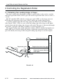
3 Controlling the Registration
Roller ................................................ 6-12
3.1 Detecting the Leading Edge of
Paper ........................................ 6-12
4 Detecting Jams ................................. 6-13
4.1 Outline ..................................... 6-13
4.2 Sequence of Jam Detection ..... 6-14
4.2.1 Delay Jam .......................... 6-14
4.2.2 Stationary Jams ................. 6-16
4.2.3 Cover Open Jam ................ 6-17
4.2.4 Jam History ....................... 6-17
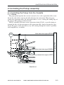
5 Disassembly and Assembly ............. 6-18
5.1 Cassette Pickup Assembly ...... 6-19
5.1.1 Remove the Cassette Pickup
Assembly ........................... 6-19
5.1.2 Removing the Cassette
Pickup Roller ..................... 6-21
5.1.3 Removing the Feeding/
Separation Roller .............. 6-22
5.1.4 Removing the Cassette
Pickup Solenoid ................ 6-22
5.1.5 Removing the Paper Size
Detecting Switch ............... 6-22
5.1.6 Removing the Cassette Paper
Sensor ................................ 6-23
5.1.7 Removing the Retry
Sensor ................................ 6-23
COPYRIGHT © 2002 CANON INC. 2001 2001 CANON iR1600/iR2000/iR1610/iR2010 SERIES REV.0 MAR. 2002
xiii
CONTENTS
5.1.8
Removing the Pickup Motor
(20 cpm model only) ......... 6-23
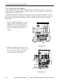
5.2 Multifeeder Tray Assembly .... 6-24
5.2.1 Removing the Multifeeder
Tray .................................... 6-24
5.2.2 Removing the Multifeeder
Pickup Roller ..................... 6-25
5.2.3 Removing the Separation
Pad ..................................... 6-26
5.2.4 Removing the Multifeeder
Paper Sensor ...................... 6-26
5.2.5 Removing the Multifeeder
Pickup Solenoid ................ 6-27
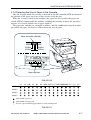
5.3 Drive Assembly ....................... 6-27
5.3.1 Removing the Drive
Assembly ........................... 6-27
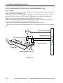
5.4 Registration Roller
Assembly ................................. 6-31
5.4.1 Removing the Registration
Roller ................................. 6-31
5.4.2 Removing the Registration
Paper Sensor ...................... 6-32
5.4.3 Removing the Registration
Clutch ................................ 6-33
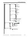
CHAPTER 7 FIXING SYSTEM
1 Outline of Operation .......................... 7-1
1.1 Outline ....................................... 7-1
2 Controlling the Fixing Temperature .. 7-3
2.1 Outline ....................................... 7-3
2.2 Controlling the Temperature ..... 7-4
2.2.1 Control at Time of
Power-On ............................. 7-5
2.2.2 Control According to the
Type of Paper ...................... 7-6
2.2.3 Control at Time of Down
Sequence .............................. 7-6
2.2.4 Control in ESS
(energy save mode) ............. 7-7
2.3 Detecting an Error ..................... 7-8
2.3.1 Outline ................................. 7-8
2.3.2 Control in Response to an
Error ..................................... 7-8
2.3.3
Conditions for Error
Detection ............................. 7-8
2.4 Protective Mechanism ............. 7-10
3 Disassembly and Assembly ............. 7-11
3.1 Removing the Fixing
Assembly ................................. 7-12
3.2 Cleaning the Inside of the
Fixing Assembly or Replacing
Its Parts .................................... 7-15
3.3 Removing the Delivery Sensor 7-15
3.4 Removing the Pressure Roller 7-16
3.5 Removing the Fixing Roller/
Fixing Heater/Separation
Claw ......................................... 7-22
3.6 Mounting the Fixing Roller/
Fixing Heater/Separation
Claw ......................................... 7-24
CHAPTER 8 EXTERNALS AND AUXILIARY
CONTROL SYSTEM
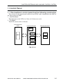
1 Control Panel ...................................... 8-1
1.1 The machine’s control panel has
the following construction ........ 8-1
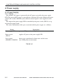
2 Power supply ...................................... 8-2
xiv
2.1 Power Supply ............................. 8-2
2.1.1 Outline ................................. 8-2
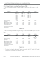
2.1.2 Rated Outputs from the Power
Supply PCB ......................... 8-4
COPYRIGHT © 2002 CANON INC. 2001 2001 CANON iR1600/iR2000/iR1610/iR2010 SERIES REV.0 MAR. 2002
CONTENTS
3
4
5
6
2.2 Protective Mechanisms ............. 8-5
2.3 High-Voltage Power Supply
Circuit ........................................ 8-5
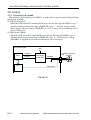
Control at Time of Energy
Save Mode .......................................... 8-6
3.1 Outline ....................................... 8-6
3.2 Control ....................................... 8-6
3.3 Operation ................................... 8-8
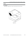
Fan ...................................................... 8-9
4.1 Outline ....................................... 8-9
4.2 Control ..................................... 8-10
4.2.1 Controlling the Speed ....... 8-10
4.2.2 Error Detection .................. 8-11
4.2.3 Sequence of Operation
(fan drive) .......................... 8-11
Back-Up Battery ............................... 8-12
5.1 Back-Up Mechanism ............... 8-12
5.1.1 Outline ............................... 8-12
5.1.2 Vanadium Lithium Secondary
Battery (BAT2) .................. 8-12
5.1.3 Lithium Battery (BAT1) .... 8-13
5.2 Back-Up Data .......................... 8-16
5.2.1 Types of Data .................... 8-16
5.2.2 Printing Out the Back-Up
Data List ............................ 8-18
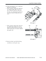
Disassembly and Assembly ............. 8-19
6.1 External Covers ....................... 8-20
6.1.1 Removing the Front
Cover ................................. 8-22
6.1.2 Removing the Control Panel
Lower Cover ...................... 8-22
6.2 Control Panel ........................... 8-23
6.2.1 Removing the Control
Panel .................................. 8-23
6.3 Main Motor .............................. 8-24
6.3.1 Removing the Main
Motor ................................. 8-24
6.4 Fan ........................................... 8-25
6.4.1 Removing the Heat
Discharge fan .................... 8-25
6.5 PCBs ........................................ 8-26
6.5.1 Removing the
DC Controller PCB ........... 8-26
6.5.2 After Replacing the
DC controller PCB ............ 8-26
6.5.3 Removing the
Image Processor PCB ....... 8-27
6.5.4 When Replacing the
Image Processor PCB ....... 8-27
6.5.5 Removing the
RAM DIMM ..................... 8-27
6.5.6 Removing the
ROM DIMM ...................... 8-28
6.5.7 Removing the Analog
Processor PCB ................... 8-28
6.5.8 After Replacing the Analog
Processor PCB ................... 8-31
6.5.9 Removing the
Power Supply PCB ............ 8-31
6.5.10 Removing the Original Detection/Reader Motor PCB .... 8-32
6.5.11 Removing the Printer Board
Unit (if equipped with
printer functions) .............. 8-32
6.5.12 Removing the Cassette
controller PCB
(20 cpm model only) ......... 8-32
CHAPTER 9 CASSETTE UNIT
1 Outline ................................................ 9-1
1.1 Outline ....................................... 9-1
1.2 Specifications and Construction
................................................... 9-1
1.3 Arrangement of Major Rollers
and Sensors ................................ 9-2
2 Pickup Assembly ................................ 9-4
2.1 Pickup Control System ............. 9-4
2.2 Pickup Control ........................... 9-7
2.3 Cassette Pickup Operation ........ 9-7
2.4 Pickup Re-Try Operation .......... 9-7
2.5 Cassette Paper Size Detection .. 9-7
COPYRIGHT © 2002 CANON INC. 2001 2001 CANON iR1600/iR2000/iR1610/iR2010 SERIES REV.0 MAR. 2002
xv
CONTENTS
3 Detecting Jams ................................... 9-8
3.1 Outline ....................................... 9-8
3.2 Sequence of Jam Detection ....... 9-8
3.2.1 Delay Jam ............................ 9-8
3.2.2 Stationary Jam ..................... 9-8
3.2.3 Jam History ......................... 9-8
4 Disassembly and Assembly ............... 9-9
4.1 Removing the Cassette Unit ... 9-10
4.2 Cassette Pickup Assembly ...... 9-12
4.2.1 Removing the Cassette
Pickup Assembly ............... 9-12
4.2.2 Removing the Cassette
Pickup Roller ..................... 9-12
4.2.3
Removing the Cassette
Pickup Solenoid ................ 9-12
4.2.4 Removing the Paper Size
Switch ................................ 9-12
4.2.5 Removing the Cassette
Paper Sensor ...................... 9-12
4.2.6 Removing the Re-Try
Sensor ................................ 9-12
4.3 PCBs ........................................ 9-13
4.3.1 Removing the Cassette Unit
Controller PCB .................. 9-13
4.4 Drive-Related Parts ................. 9-13
4.4.1 Removing the Pickup
Motor ................................. 9-13
CHAPTER 10 INNER 2-WAY TRAY
1 Specifications ................................... 10-1
1.1 System ..................................... 10-1
1.2 Arrangement of Rollers and
Sensors ..................................... 10-2
2 Controlling Delivery Operation ....... 10-3
2.1 Controlling Delivery
Operation ................................. 10-3
2.2 Selecting a Delivery Slot
(user mode) .............................. 10-3
3 Detecting Jams ................................. 10-4
3.1 Outline ..................................... 10-4
3.2 Sequence of Jam Detection ..... 10-4
3.2.1 Delay Jam .......................... 10-4
3.2.2 Stationary Jam ................... 10-4
3.2.3 Jam History ....................... 10-4
4 Disassembly and Assembly ............. 10-5
4.1 Removing the Inner 2-Way
Unit .......................................... 10-6
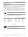
CHAPTER 11 INSTALLATION
1 Selecting the Site of Installation ..... 11-1
2 Unpacking and Installing the
Machine ............................................ 11-3
2.1 Points to Note Before
Starting the Work .................... 11-3
2.2 Installing the Machine ............ 11-4
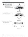
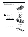
2.3 Unpacking and Removing the
Fixing Members ...................... 11-5
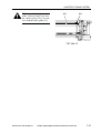
2.4 Removing the Dummy Drum .. 11-7
2.5 Mounting the Drum Unit ........ 11-9
2.6 Mounting the Toner Cartridge
............................................... 11-11
xvi
2.7 Putting Paper in the Cassette
............................................... 11-14
2.8 Placing Paper in the
Multifeeder Tray .................... 11-18
2.9 Checking the Copy Images ... 11-20
2.10 Selecting the Country/Region
through Service Operation .... 11-21
2.11 Setting the Date/Time
(user mode) ............................ 11-22
2.12 Storing the Specifications
Report .................................... 11-23
COPYRIGHT © 2002 CANON INC. 2001 2001 CANON iR1600/iR2000/iR1610/iR2010 SERIES REV.0 MAR. 2002
CONTENTS
2.13 Setting the Fax Functions
(if equipped with fax
functions) ............................... 11-24
2.13.1 Connecting the Line ......... 11-24
2.13.2 Setting the Dialing
Method ............................. 11-24
2.13.3 Communications Test ....... 11-24
2.14 Checking the Printer Functions
(if equipped with printer
functions) ............................... 11-25
3 Relocating the Machine ................... 11-26
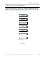
4 Flow of accessory installation ......... 11-27
(if equipped with a fax function) ...... 11-27
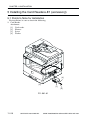
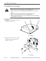
5 Installing the Card Readere-E1
(accessory) ...................................... 11-28
5.1 Points to Note for
Installation .............................. 11-28
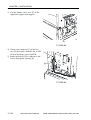
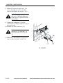
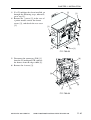
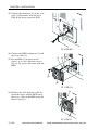
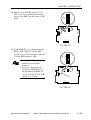
5.2 Installation .............................. 11-29
5.3 Setting and Checking After
Installation ............................. 11-33
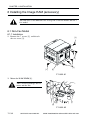
6 Installing the Image RAM
(accessory) ...................................... 11-34
6.1 Non-Fax Model ..................... 11-34
6.1.1 Installation ....................... 11-34
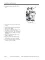
6.2 FAX Model ............................ 11-36
6.2.1 Before Starting the Work 11-36
6.2.2 Mounting the RAM ......... 11-36
7 Installing the Remote Diagnostic
Device II (accessory) ..................... 11-39
7.1 Parts to Procure ..................... 11-39
7.2 Unpacking .............................. 11-39
7.3 Installation to the Copier ...... 11-40
CHAPTER 12 MAINTENANCE AND INSPECTION
1 Periodically Replaced Parts ............. 12-1
1.1 Copier ...................................... 12-1
1.2 Cassette Unit ........................... 12-1
1.3 Inner 2-Way Tray ..................... 12-1
2 Guide to Durables ............................ 12-2
2.1 Checking the Timing of
Replacement ............................. 12-2
2.2 Copier ....................................... 12-2
2.3 Cassette Unit ............................ 12-2
2.4 Inner 2-Way Tray ..................... 12-2
3 Basic Service Work ........................... 12-3
CHAPTER 13
3.1 Basic Service Work .................. 12-3
4 Cleaning During a Visit ..................... 12-4
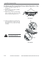
5 Points to Note When Storing/Handling the
Drum Unit ......................................... 12-7
5.1 Outline ...................................... 12-7
5.2 Storage and Handing After Removing the Packaging Seal ............ 12-7
5.2.1 Storage After Removing the
Packaging Seal .................. 12-7
5.2.2 Points to Note When Handling
the Drum Unit ................... 12-8
TROUBLESHOOTING
1 Image Adjustment Basic
Procedure .......................................... 13-1
1.1 Image Adjustment Basic
Procedure ................................. 13-1
2 Standards and Adjustments .............. 13-3
2.1 Image Adjustments .................. 13-3
2.1.1 Standards for Image
Position .............................. 13-3
2.1.2
2.1.3
2.1.4
Adjusting the Image
Position .............................. 13-4
Adjusting the Leading Edge
Margin for the Printer Unit
(if equipped printer
functions) ........................... 13-5
Adjusting the Image
Position for Copying ......... 13-7
COPYRIGHT © 2002 CANON INC. 2001 2001 CANON iR1600/iR2000/iR1610/iR2010 SERIES REV.0 MAR. 2002
xvii
CONTENTS
2.1.5
Adjusting the Image Position
for ADF Copying ............... 13-9
2.2 Fixing System ........................ 13-11
2.2.1 Checking the Fixing
Roller Pressure (nip) ....... 13-11
2.3 Electrical Parts ...................... 13-12
2.3.1 When Replacing the
Major Parts ...................... 13-12
2.3.2 Gain Auto Adjustment .... 13-12
2.3.3 When Replacing the
Contact Sensor ................ 13-12
2.3.4 When Replacing the
Image Processor PCB ..... 13-13
2.3.5 When Replacing the
DC Controller PCB ......... 13-15
2.3.6 When Replacing the
Analog Processor PCB .... 13-15
2.4 Checking the Sensors ............ 13-16
2.4.1 Checking the Sensors ...... 13-16
3 Troubleshooting Image/
Operation Faults ............................. 13-19
3.1 Making Initial Checks on
Image Faults .......................... 13-19
3.1.1 Site of Installation ........... 13-19
3.1.2 Checking the Originals ... 13-19
3.1.3 Copyboard Cover and
Copyboard Glass
(standard white plate) ..... 13-19
3.1.4 Checking the Transfer
Charging Roller/
Static Eliminator ............. 13-20
3.1.5 Checking the Drum Unit .. 13-20
3.1.6 Checking the Paper ......... 13-20
3.1.7 Image Adjustment Basic
Procedure ......................... 13-20
3.1.8 Others .............................. 13-20
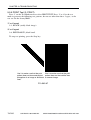
3.2 Image Fault Samples ............. 13-22
3.3 Troubleshooting Image
Faults ..................................... 13-23
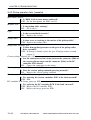
3.3.1 The copy is too light.
(halftone only) ................. 13-23
3.3.2 The copy is too light. (both halftone and solid black) ........ 13-23
3.3.3 The copy is too light. (entire
copy, appreciably) ........... 13-23
xviii
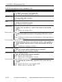
3.3.4
The copy has uneven density.
(darker along front) ......... 13-26
3.3.5 The copy has uneven density.
(lighter along front) ........ 13-26
3.3.6 The copy is foggy.
(entire copy) .................... 13-27
3.3.7 The copy is foggy.
(feeding direction) .......... 13-28
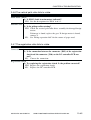
3.3.8 The copy has black lines.
(feeding direction, fuzzy,
thick) ............................... 13-28
3.3.9 The copy has black lines. (feeding direction, fine) ............ 13-28
3.3.10 The copy has white strips.
(feeding direction) ............ 13-29
3.3.11 The copy has white lines.
(feeding direction) ............ 13-29
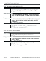
3.3.12 The output has white strips.
(cross-feeding direction) . 13-30
3.3.13 The back of the copy is
soiled ............................... 13-31
3.3.14 The copy has a poor
fixing ................................ 13-32
3.3.15 The copy has displaced registration. (leading edge extremely
excessive margin) ............. 13-33
3.3.16 The copy has displaced registration. (leading edge, excessive
margin) ............................. 13-33
3.3.17 The copy has displaced registration. (leading edge, no
margin) ............................. 13-33
3.3.18 The copy has blurred
images .............................. 13-34
3.3.19 The copy is foggy.
(cross-feeding direction) . 13-35
3.3.20 The copy has poor
sharpness. ........................ 13-36
3.3.21 The copy is blank. ............ 13-37
3.3.22 The copy is solid black. .... 13-38
3.3.23 The copy has a black line
(stream reading). ............. 13-39
3.4 Troubleshooting
Malfunctions .......................... 13-40
3.4.1 AC power is absent. ......... 13-40
COPYRIGHT © 2002 CANON INC. 2001 2001 CANON iR1600/iR2000/iR1610/iR2010 SERIES REV.0 MAR. 2002
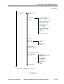
CONTENTS
3.4.2
3.4.3
DC power is absent. ......... 13-41
Pickup operation fails.
(cassette) .......................... 13-42
3.4.4 Pickup operation fails.
(multifeeder tray) ............ 13-43
3.4.5 Pickup operation fails.
(cassette unit) .................. 13-44
3.4.6 The vertical path roller
fails to rotate. .................. 13-45
3.4.7 The registration roller
fails to rotate. .................. 13-45
3.4.8 The contact sensor
fails to go ON. ................. 13-46
3.4.9 The speaker fails to
operate. ............................ 13-46
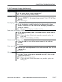
3.4.10 The ‘Add Toner’ message
fails to go OFF. ................ 13-47
3.4.11 The ‘Add Paper’ message
fails to go OFF. (machine and
cassette unit) ................... 13-48
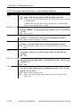
3.4.12 The ‘Add Paper’ message
fails to go OFF.
(multifeeder tray) ............ 13-49
3.4.13 The ‘Jam’ message
fails to go OFF. ................ 13-49
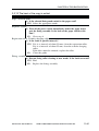
3.4.14 The ‘Waste Toner Full’ message
does not go OFF. .............. 13-50
3.4.15 The ‘Controller Card Set’ message does not go ON. ....... 13-50
3.4.16 The ‘Control Card Set’ message does not go OFF. ..... 13-50
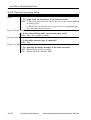
3.5 Troubleshooting Feeding
Faults ..................................... 13-51
3.5.1 Outline ............................. 13-51
3.5.2 Pickup Assembly ............. 13-52
3.5.3 Transfer/
Feeding Assembly ........... 13-53
3.5.4 Fixing/
Delivery Assembly .......... 13-54
3.5.5 Feeding Fault
(double feeding) .............. 13-55
3.5.6 Feeding Faults
(wrinkling) ....................... 13-56
4 Arrangement and Functions of
Electrical Parts ............................... 13-57
4.1 Outline ................................... 13-57
4.1.1 Outline ............................. 13-57
4.1.2 Checking the Sensors ...... 13-57
4.2 Clutches, Solenoids,
Motors, and Fans ................... 13-58
4.3 Sensors ................................... 13-59
4.4 PCBs ...................................... 13-60
4.5 Switches, Others .................... 13-62
4.6 Cassette Unit ......................... 13-64
4.7 Inner 2-Way Tray ................... 13-66
4.8 Variable Resistors (VR),
Light-Emitting Diodes (LED),
and Check Pins ...................... 13-67
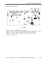
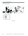
4.8.1 Image Processor PCB ..... 13-68
4.8.2 DC Controller PCB ......... 13-69
4.8.3 Power Supply PCB .......... 13-70
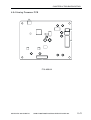
4.8.4 Analog Processor PCB .... 13-71
4.8.5 1-Cassette Unit
Controller PCB ................ 13-72
4.8.6 2/3-Cassette Unit
Controller PCB ................ 13-72
5 Service Mode ................................. 13-73
5.1 Outline ................................... 13-73
5.2 Using the Mode ..................... 13-75
5.3 Service Mode Menus ............ 13-76
5.4 Setting the parameters ........... 13-84
5.4.1 Registering the Bit Switch
(#1 SSSW) ....................... 13-84
5.4.2 Menu Switch Setting
(#2 MENU) ................... 13-111
5.4.3 Setting Numeric Parameters
(#3 NUMERIC Param.) . 13-113
5.4.4 SPECIAL Setting
(#4A SPECIAL) ............ 13-120
5.4.5 NCU Setting
(#4B NCU) .................... 13-120
5.4.6 ISDN Setting
(#4C ISDN) ................... 13-120
5.4.7 Selecting the Country/
Region of Installation
(#5 TYPE) ..................... 13-121
COPYRIGHT © 2002 CANON INC. 2001 2001 CANON iR1600/iR2000/iR1610/iR2010 SERIES REV.0 MAR. 2002
xix
CONTENTS
5.4.8
Setting Original Read
Functions
(#6 SCANNER) ............. 13-121
5.4.9 Setting the Printer Parameters
(#7 PRINTER) ............... 13-126
5.4.10 PDL (#8 PDL) ............... 13-129
5.4.11 Counters
(#9 COUNTER) ............ 13-130
5.4.12 Generating a Report
(#10 REPORT) .............. 13-133
5.4.13 Downloading
(#11 DOWNLOAD) ...... 13-134
5.4.14 Clear (#12 CLEAR) ...... 13-135
5.4.15 ROM Indication
(#13 ROM) .................... 13-136
5.4.16 Resetting the CS Unit
Position (#14 CS SET) .. 13-136
5.5 Test Mode (TEST MODE) .. 13-137
5.5.1 Outline ........................... 13-137
5.5.2 Test Mode Menu ........... 13-138
5.5.3 D-RAM Test
(1: D-RAM) ................... 13-143
5.5.4 CCD Test
(2: CCD TEST) ............. 13-145
5.5.5 PRINT Test
(3: PRINT) ..................... 13-146
5.5.6
MODEM NCU Test
(4: MODEM NCU) ....... 13-147
5.5.7 Faculty Test
(6: FACULTY TEST) .... 13-150
5.5.8 Book Read Test
(8: BOOK TEST) .......... 13-160
5.6 Report .................................. 13-161
5.6.1 User Report ................... 13-161
5.6.2 Service Report ............... 13-164
6 Self Diagnosis .............................. 13-176
6.1 Outline ................................. 13-176
6.2 Error Codes .......................... 13-177
6.2.1 Error Codes Used for
the Machine ................... 13-177
6.2.2 Finisher Error Codes ..... 13-183
6.3 Fax Error Code .................... 13-190
6.3.1 Service Error Code
Output ............................ 13-190
6.3.2 Error Codes ................... 13-190
6.3.3 Causes and Remedies for
User Error Codes ........... 13-194
6.3.4 Causes and Remedies for
Service Error Codes ...... 13-201
CHAPTER 14 VERSION UP
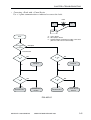
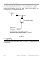
1 Upgrading ......................................... 14-1
1.1 Outline ..................................... 14-1
2 Upgrading by Downloading ............. 14-3
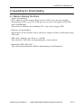
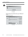
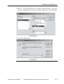
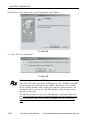
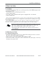
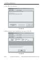
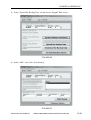
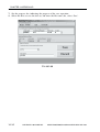
2.1 Before Starting the Work ........ 14-3
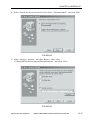
2.2 Installing the USB Driver
(only if Windows 98 or
Windows 98SE) ....................... 14-4
2.3 Installing the Firmware ......... 14-10
2.4 Downloading the System
Software ................................. 14-13
2.5 Downloading for G3 FAX ..... 14-20
2.6 Downloading for the
Finisher-L1 ............................ 14-21
xx
2.6.1 Outline ............................. 14-21
2.6.2 Downloading ................... 14-22
3 Back Up Data ................................. 14-27
3.1 Outline ................................... 14-27
3.2 Backing Up Data ................... 14-27
3.2.1 Making Preparations ....... 14-27
3.2.2 Making Connections ....... 14-28
3.2.3 Backing Up Data ............. 14-29
3.2.4 Downloading Backup
Data .................................. 14-34
3.2.5 Managing Backup Data .... 14-38
COPYRIGHT © 2002 CANON INC. 2001 2001 CANON iR1600/iR2000/iR1610/iR2010 SERIES REV.0 MAR. 2002
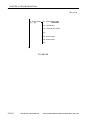
CONTENTS
APPENDIX
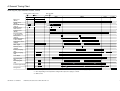
A General Timing Charts ...................... A-1
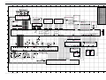
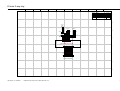
B General Circuit Diagram .................. A-3
C 1-cassette unit .................................... A-5
D 2/3-cassette unit ................................ A-6
E Inner 2-way tray ................................ A-7
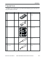
F Special Tools ..................................... A-9
G Solvents and Oils ............................ A-11
COPYRIGHT © 2002 CANON INC. 2001 2001 CANON iR1600/iR2000/iR1610/iR2010 SERIES REV.0 MAR. 2002
xxi
CHAPTER 1
INTRODUCTION
COPYRIGHT © 2002 CANON INC. 2001 2001 CANON iR1600/iR2000/iR1610/iR2010 SERIES REV.0 MAR. 2002
CHAPTER 1 INTRODUCTION
1 Features
1.1 Features
1.High-Speed, High Image Quality
Copying speed
16 copies/min (iR1600/iR1610F ; 1-to-N, from cassette)
20 copies/min (iR2000/iR2010F ; 1-to-No: from cassette)
Reading resolution
: 600 dpi x 600 dpi
Printing resolution
Copying
: 1,200 (equivalent) x 600 dpi
PDL output : 2,400 (equivalent) x 600 dpi
2. Large Paper Source
With the addition of accessories, as many as 1,100 sheets (80 g/m2) may be accommodated.
Multifeeder : 100 sheets (A4R, A4, B5, B5R, A5, A5R; 80 g/m2)
• 16cpm model Cassette
Cassette 1 : 250 sheets
1-cassette unit (accessory) : 250 sheets
3-cassette unit (accessory) : 250 sheets x 3
• 20cpm model Cassette
Cassette 1 : 250 sheets
Cassette 2 : 250 sheets
2-cassette unit (accessory) : 250 sheets x 2
3. Mixed Paper Sizes (of same configuration)
Installation of an ADF will enable mixing of different paper sizes (of the same configuration).
4.Networking
Mounting of a printer board and network interface board will enable the use of the machine as a network printer in an Ethernet environment.
5.Hard Disk
Installation of a hard disk (accessory) will enable storage of image data on the hard
disk. Since the images will be read from the hard disk, multiple sets of copies may be obtained faster (RIP-once function).
COPYRIGHT© 2002 CANON INC. 2000 CANON iR1600/iR2000/iR1610/iR2010 SERIES REV.0 MAR. 2002
1-1
CHAPTER 1 INTRODUCTION
6.Selection of a Delivery Tray
Installation of an inner 2-way tray (accessory) will enable the selection of trays separately for copier and printer output (in user mode).
7.Auto Start/Interrupt Copying
The existing models retains no more than one job. The machine, however, keeps jobs on
queue, thus enabling auto-start/interrupt copying.
1-2
COPYRIGHT© 2002 CANON INC. 2000 CANON iR1600/iR2000/iR1610/iR2010 SERIES REV.0 MAR. 2002
CHAPTER 1 INTRODUCTION
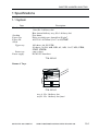
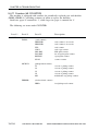
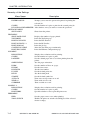
2 Specifications
2.1 Copier
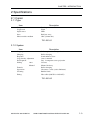
2.1.1 Type
Item
Body
Copyboard
Light source
Lens
Photosensitive medium
Description
Desktop
Fixed
LED
Rod lens array
OPC (30-mm dia.)
T01-201-01
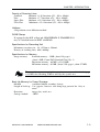
2.1.2 System
Item
Copying
Charging
Exposure
Copy density adjustment
Development
Pickup
Auto
Manual
Transfer
Separation
Cleaning
Fixing
Description
Indirect photoelectric reproduction
Roller charging
Semiconductor laser
Auto or manual
Dry, 1-component toner projection
Cassette
Manual feed tray
Roller charging
Curvature + static (static eliminator)
Rubber blade
Heat roller (800 W for 120/230V)
T01-201-02
COPYRIGHT© 2002 CANON INC. 2000 CANON iR1600/iR2000/iR1610/iR2010 SERIES REV.0 MAR. 2002
1-3
CHAPTER 1 INTRODUCTION
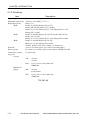
2.1.3 Functions
Item
Description
Original type
Maximum original size
Reproduction ratio
4R4E
4R3E
4R2E
Wait time
First copy time
Continuous copying
Copy size
Cassette
Sheet, book, 3-D (2 kg max.)
A3/279.4 x 431.8mm (11" x 17")
Direct (1:1)
Reduce I (1:0.500), Reduce II (1:0.707)
Reduce III (1:0.816), Reduce IV (1:0.865)
Enlarge I (1:1.154), Enlarge II (1:1.224), Enlarge III (1:1.414)
Enlarge IV (1:2.000)
Reduce I (1:0.500), Reduce II (1:0.647), Reduce III (1:0.733)
Reduce IV (1:0.786)
Enlarge I (1:1.214), Enlarge II (1:1.294), Enlarge III (1:2.000)
Reduce I (1:0.500), Reduce II (1:0.707)
Enlarge I (1:1.414), Enlarge II (1:2.000)
Zoom (1:0.500 to 2.00; 50% to 200%; 1%-increment)
30 sec or less from power-on (at 20°C room temperature)
Less than 8.2 sec (from copier cassette; Direct, A4/LTR, non-AE)
99 copies max.
AB :
Inch :
Multifeeder
pickup
AB :
Inch
A3 max.
A5 min.
11x17 (279.4 x 431.8 mm) max.
STMT min.
A3 max.
Postcard min.
11x17 (279.4 x 431.8 mm) max.
STMT min.
T01-201-03
1-4
COPYRIGHT© 2002 CANON INC. 2000 CANON iR1600/iR2000/iR1610/iR2010 SERIES REV.0 MAR. 2002
CHAPTER 1 INTRODUCTION
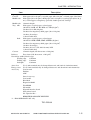
Item
Description
Paper type
Cassette
Multifeeder
Plain paper (60 to 90 g/m2), recycled paper (60 to 90 g/m2), colored paper, label sheet
Plain paper (60 to 90 g/m2), thick paper (90 to 128 g/m2), recycled paper (60 to 90 g/
m2), colored paper, transparency, postcard, double-postcard, envelope
Multifeeder 10 mm in height
Tray AB:
Plain paper, recycled paper, colored paper
100 sheets if A4R, A4, B5, B5R, A5, A5R (80 g/m2)
50 sheets if A3, B4 (80 g/m2)
50 sheets if transparency, thick paper (90 to 128 g/m2)
10 sheets if envelope
1 sheet if label sheet
Inch:
Plain paper, recycled paper, colored paper
100 sheets if LTR, LTRR, STMT, STMTR (80 g/m2)
50 sheets if transparency, thick paper (90 to 128 g/m2)
10 sheets if envelope
50 sheets if 11x17 (279.4x431.8 mm), LGL
1 sheet if label sheet
Cassette
25 mm in depth (250 sheets max. of 80 g/m2)
Delivery
Face-down (250 sheets max. of 80 g/m2)
Non-image width (if book copy)
Leading edge
3.0±2mm
Trailing edge
3.0±2mm
Left/right
3.0±2mm
Auto clear
Yes (2 min standard; may be changed between 0 and 9 min in 1-min increment)
Energy saver
Yes (15 min standard; may be changed between 3 and 30 min in 1-min increment)
Accessory
Cassette unit
Finisher
ADF
Inner 2-way tray
Card reader
Hard disk
Expansion RAM
Flash ROM
PS module
Network interface board
PCL printer board
G3 expansion kit *1
REMOTE DIAGNOSTIC DEVICE II
*1 : iR1610F/iR2010F 120V only
T01-210-04
COPYRIGHT© 2002 CANON INC. 2000 CANON iR1600/iR2000/iR1610/iR2010 SERIES REV.0 MAR. 2002
1-5
CHAPTER 1 INTRODUCTION
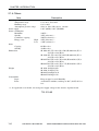
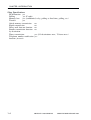
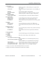
2.1.4 Others
Item
Description
Operating environment
Temperature range
Humidity range
Atmospheric pressure range
Power supply
Power consumption
Maximum
Standby
Continuous copying
Energy saver
High
Low
Noise
Copying
Standby
Dimensions
Weight
Consumables
Paper
Toner
15 to 30°C; 59 to 86°F
10% to 80%
810.6 to 1013.3 hPa (0.8 to 1.0 atm)
120V (60Hz), 230V (50/60Hz)
940W *1
30W (reference) *1
900W (reference) *1
20W (reference) *1
4.8W (reference) *1
66 dB or less
40 dB or less
iR 1600 615 (W) x 631 (D) x 560 (H) mm/24.0 (W) x
24.8 (D) x 22.0 (H) in.
iR 2000 615 (W) x 631 (D) x 645 (H) mm/24.0 (W) x
24.8 (D) x 25.1 (H) in.
iR1610F 615 (W) x 631 (D) x 662 (H) mm/24.0 (W) x
24.8 (D) x 25.9 (H) in.
iR2010F 615 (W) x 631 (D) x 747 (H) mm/24.0 (W) x
24.8 (D) x 29.5 (H) in.
iR 1600 38.0kg/83.8 lb
iR 2000 43.4kg/95.7 lb
iR1610F 44.0kg/97.0 lb
iR2010F 50.5kg/111 lb
Keep wrapped to avoid humidity.
Avoid direct sunshine, and keep at 40°C (104°F) 85% or
less.
*1 : In copyboard cover model; for rated power supply voltage in the absence of printer board.
T01-210-05
1-6
COPYRIGHT© 2002 CANON INC. 2000 CANON iR1600/iR2000/iR1610/iR2010 SERIES REV.0 MAR. 2002
CHAPTER 1 INTRODUCTION
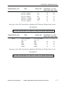
Reproduction ratio
Direct
Size
Paper size
A3 (297 x 420mm)
A4 (297 x 420mm)
B4 (297 x 420mm)
B5 (297 x 420mm)
A4R (297 x 420mm)
B5R (297 x 420mm)
A5 (297 x 420mm)
A3
A4
B4
B5
A4R
B5R
A5
Copies/min (1-to-N)
16cpm model 20cpm model
9
16
10
16
12
13
16
9
20
10
20
15
16
20
Auto paper select ON, Auto density adjustment ON, Non-sort, Pickup from cassette
T01-201-06
The above specifications are subject to change for product improvement.
Reproduction ratio
Size
Paper size
Direct
279.4 x 431.8mm
(11" x 17")
LTR
LGL
LTRR
STMT
279.4 x 431.8mm
(11" x 17")
LTR
LGL
LTRR
STMT
Copies/min (1-to-N)
16cpm model 20cpm model
9
9
16
10
12
16
20
10
16
20
Auto paper select ON, Auto density adjustment ON, Non-sort, Pickup from cassette
T01-201-07
The above specifications are subject to change for product improvement.
COPYRIGHT© 2002 CANON INC. 2000 CANON iR1600/iR2000/iR1610/iR2010 SERIES REV.0 MAR. 2002
1-7
CHAPTER 1 INTRODUCTION
2.2 Cassette Unit
Item
Description
Pickup
Paper type
Cassette
Serial Number
Claw-less (retard) method
Same as host.
25 mm deep (250 sheets of 80 g/m2 paper max.)
1-cassette type : XGQxxxxx
XHVxxxxx
2-cassette type : XGRxxxxx
XHWxxxxx
3-cassette type : XGSxxxxx
XHXxxxxx
Dimensions
1-cassette type
2-cassette type
3-cassette type
560 (W) x 564 (D) x 91 (H) mm
22.0 (W) x 22.0 (D) x 3.54 (H) in.
560 (W) x 564 (D) x 176 (H) mm
22.0 (W) x 22.0 (D) x 6.79 (H) in.
560 (W) x 564 (D) x 261 (H) mm
22.0 (W) x 22.0 (D) x 10.2 (H) in.
Weight
1-cassette type
2-cassette type
3-cassette type
Power supply
Operating environment
Temperature range
Humidity range
Atmospheric pressure
6 kg/13.2 lb (approx.; including cassette)
12 kg/26.5 lb (approx.; including cassette)
18 kg/39.7 lb (approx.; including cassette)
DC power from host
Same as host
T01-202-01
The above specifications are subject to change for product improvement.
1-8
COPYRIGHT© 2002 CANON INC. 2000 CANON iR1600/iR2000/iR1610/iR2010 SERIES REV.0 MAR. 2002
CHAPTER 1 INTRODUCTION
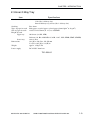
2.3 Inner 2-Way Tray
Item
Number of bins
Stacking
Type of paper in stack
Size of paper in stack
Height of stack
Upper tray
Lower tray
Dimensions
Weight
Power supply
Specifications
2 bins in total
1 bin (No. 2 delivery slot)
Internal delivery tray of host (No. 1 delivery slot)
Face-down
Plain paper, recycled paper, colored paper (from 64g/m2 to 90 g/m2)
A3/279.4 x 431.8mm (11 x 17) to A5/STMT
100 sheets (A4, B5, LTR)
50 sheets (A3, B4, A4R, B5R, A5, A5R, 11x17, LGL, LTRR, STMT, STMTR)
same as host
149 (W) x 420 (D) x 254 (H) mm
5.9 (W) x 16.5 (D) x 9.8 (H) in
approx. 3.5kg/7.7Ib
DC 24V/5V from host
T01-203-01
COPYRIGHT© 2002 CANON INC. 2000 CANON iR1600/iR2000/iR1610/iR2010 SERIES REV.0 MAR. 2002
1-9
CHAPTER 1 INTRODUCTION
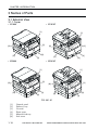
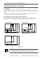
3 Names of Parts
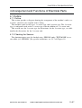
3.1 External View
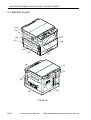
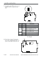
3.1.1 Copier
• iR1600
• iR1610F
[1]
[1]
[2]
[6]
[3]
[5]
[2]
[6]
[3]
[5]
[4]
[4]
• iR2000
• iR2010F
[1]
[1]
[2]
[6]
[2]
[6]
[3]
[5]
[3]
[5]
[4]
[4]
F01-301-01
[1]
[2]
[3]
[4]
[5]
[6]
1-10
Control panel
Delivery tray
Cassette
Front cover
Manual feed tray
Left cover
COPYRIGHT© 2002 CANON INC. 2000 CANON iR1600/iR2000/iR1610/iR2010 SERIES REV.0 MAR. 2002
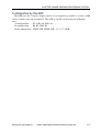
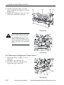
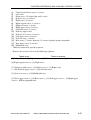
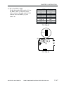
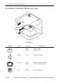
CHAPTER 1 INTRODUCTION
[3]
[4]
[5]
[6]
[2]
[1]
[11]
[10]
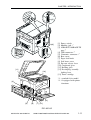
[1] Power switch
[2] Modular jack *1
[3] 10BASE-T/100BASE-TX
port *2
[4] USB connector *2
[5] Centronics connector *2
[6] Rear cover
[7] Paper feed knob
[8] Left lower cover
[9] Pressure release lever
[10] Copyboard glass
[11] Reading glass
[12] Developing assembly
locking lever
[13] Toner cartridge
*1 : standard if fax model
*2 : if equipped with printer
functions
[9]
[13]
[8]
[9]
[7] [12]
F01-301-02
COPYRIGHT© 2002 CANON INC. 2000 CANON iR1600/iR2000/iR1610/iR2010 SERIES REV.0 MAR. 2002
1-11
CHAPTER 1 INTRODUCTION
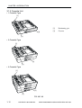
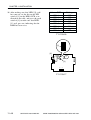
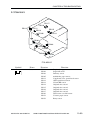
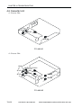
3.1.2 Cassette Unit
• 1-Cassette Type
[1]
[1]
[2]
Positioning pin
Cassette
[2]
[1]
• 2-Cassette Type
[1]
[2]
[1]
• 3-Cassette Type
[1]
[2]
[1]
F01-301-03
1-12
COPYRIGHT© 2002 CANON INC. 2000 CANON iR1600/iR2000/iR1610/iR2010 SERIES REV.0 MAR. 2002
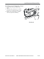
CHAPTER 1 INTRODUCTION
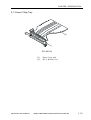
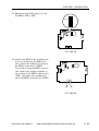
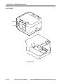
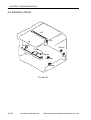
3.1.3 Inner 2-Way Tray
[2]
[1]
F01-301-04
[1]
[2]
Inner 2-way unit
No. 2 delivery tray
COPYRIGHT© 2002 CANON INC. 2000 CANON iR1600/iR2000/iR1610/iR2010 SERIES REV.0 MAR. 2002
1-13
CHAPTER 1 INTRODUCTION
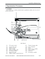
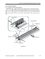
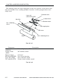
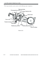
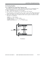
3.2 Cross Section
3.2.1 Copier
[1] [2]
[3]
[25]
[24]
[23]
[22]
[4]
[21]
[20]
[19]
[18]
[17]
[5]
[16]
[15]
[14]
[13]
[6]
[12] [11][10]
[9] [8] [7]
F01-302-01
1-14
COPYRIGHT© 2002 CANON INC. 2000 CANON iR1600/iR2000/iR1610/iR2010 SERIES REV.0 MAR. 2002
CHAPTER 1 INTRODUCTION
[1]
[2]
[3]
[4]
[5]
[6]
[7]
[8]
[9]
[10]
[11]
[12]
[13]
CS unit
ADF reading glass
Copyboard glass
Laser scanner unit
Speaker
Cassette
Toner cartridge
Developing assembly
Pick roller
Feeding roller
Separation roller
Vertical path roller
Registration roller roll
[14]
[15]
[16]
[17]
[18]
[19]
[20]
[21]
[22]
[23]
[24]
[25]
Registration roller
Manual feed separation pad
Manual feed pickup roller
Developing cylinder
Transfer charging roller
Photosensitive drum
Drum unit
Multifeeder tray
Fixing pressure roller
Fixing roller
Fixing assembly
Delivery roller
COPYRIGHT© 2002 CANON INC. 2000 CANON iR1600/iR2000/iR1610/iR2010 SERIES REV.0 MAR. 2002
1-15
CHAPTER 1 INTRODUCTION
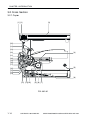
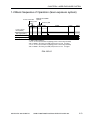
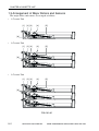
3.2.2 Cassette Unit
• 1-Cassette Type
[1]
[2] [3]
[4]
[5]
[2] [3]
[4]
[5]
[2] [3]
[4]
[5]
• 2-Cassette Type
[1]
• 3-Cassette Type
[1]
F01-302-02
[1]
[2]
[3]
[4]
[5]
1-16
Vertical path roller
Separation roller
Feeding roller
Pickup roller
Cassette
COPYRIGHT© 2002 CANON INC. 2000 CANON iR1600/iR2000/iR1610/iR2010 SERIES REV.0 MAR. 2002
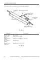
CHAPTER 1 INTRODUCTION
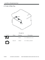
3.2.3 Inner 2-Way Tray
[1] [2]
[3]
F01-302-03
[1]
[2]
[3]
Vertical path roller
Delivery roller
No. 2 delivery tray
COPYRIGHT© 2002 CANON INC. 2000 CANON iR1600/iR2000/iR1610/iR2010 SERIES REV.0 MAR. 2002
1-17
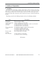
CHAPTER 1 INTRODUCTION
4 Control Panel
4.1 Control Panel
4.1.1 Control Panel for a Non-Fax Model
The machine is equipped with one power switch, and the machine is supplied with
power when the switch is turned on.
[2]
[1]
[6]
[4]
[8]
[5]
[3]
[10]*
[7]
[9]
[12]*
[11]*
[13]*
123
Monitor
Job
HDD
Alarm
Menu
Itern
Value
Enter/Cancel
Special Features
OK
A
1:1
[36]
[37]
Online
[34]
[35]
[32]
[33]
[31]
#
[30]
1
2
3
4
5
6
7
8
9
ID
0
C
[28] [26] [24]
[29] [27] [25]
GO
[22]
[23]
Shift
I
[20]
[21]
[18]*
[19]*
[16]*
[17]*
[14]*
[15]*
* Enabled only if the machine is equipped with a printer function.
F01-401-01
1-18
COPYRIGHT© 2002 CANON INC. 2000 CANON iR1600/iR2000/iR1610/iR2010 SERIES REV.0 MAR. 2002
CHAPTER 1 INTRODUCTION
No.
Key/LED name
[1]
[2]
[3]
[4]
[5]
[6]
Counter key
Paper Select indicator
Jam Location indicator
Jam indicator
LCD display
System key and indicator
[7]
[8]
[9]
[10]
Reset key
Numeric keypad
Energy Saver key
On Line indicator*
[11] Job indicator*
[12] HDD indicator*
[13] Alarm indicator*
[14] Enter/Cancel key*
[15] Value key*
[16] Shift key*
[17] Item key*
[18] Go key*
[19] Menu key*
[20]
[21]
[22]
[23]
[24]
[25]
Stop key
Main Power indicator
Start key
Clear key
ID/#key
Interrrupt key
Description
Press it to indicate the number of prints to make.
Press it to indicate the selected cassette or stack bypass.
Press it to indicate the location of a paper jam.
Check it to see if a paper jam has occurred.
Use it to bring up various settings screens.
Press it to switch over printer functions; it remains ON when a
printer function is in use.
Press it to return the copying mode to default settings.
Use it to set how may copies to make.
Use it to end energy save mode.
Check it to see if the machine is in on-line state; it flashes while
printing takes place.
Check it to see if data reception is under way.
Check it to see if a hard disk is installed; it flashes while the
hard disk is being accessed.
Check it to see if an error has occurred.
Press it to store/set a selected item.
With an item name displayed, press the Value key to step
through the item’ s values. Press Shift and Value keys to step
through the values in reverse order. Some items have a large
range of numbers from which to choose a value.
Press this key to scroll through menu or settings items in reverse order.
With a menu name displayed, press the Item key to scroll
through all the items on the menu and return to the first item.
To scroll back through the items in the opposite direction, press
the Shift and Item keys.
Takes the printer off-line and brings it back on line. When the
On Line indicator is on, the printer is ready to receive data and
print. When the On Line Indicator is off, the printer is off-line,
and you can use the other keys on the printer control panel to
view and change settings.
With the printer off-line, press the Menu key to scroll through
the menu names and return to the first menu name. To scroll
back through the menu names in the opposite directin, press
the Shift and Menu keys.
Press it to stop copying operation.
Check it to see if the machine is ON.
Press it to start copying operation.
Press it to clear registration/setting contents.
Press it when making settings in ID mode.
Use it to select/cancel interrupt mode.
COPYRIGHT© 2002 CANON INC. 2000 CANON iR1600/iR2000/iR1610/iR2010 SERIES REV.0 MAR. 2002
1-19
CHAPTER 1 INTRODUCTION
[26] Additional Function key
[27]
[28]
[29]
[30]
Cursor key
OK key
Zoom key
Back key
[31] Reduce/Direct/Enlarge key
[32] Light/AE/Dark key
[33] Image Quality key
[34] Paper Select key
[35] Finisher key
[36] Special Features key
[37] Monitor key
Use it to bring up the Additional Functions (user mode) Settings screen.
Use it to select an item when using menu settings.
Use it to set a mode or function.
Use it to make zoom settings.
Use it to return to the previous screen when making menu settings.
Use it to set Reduce, Dirt, or Enlarge copy settings.
Use the AE key to register/set automatic exposure settings.
Use the Light/Dark key to manually adjust the copy density.
Use it to select a level of image quality from text, text/photo,
and photo modes.
Use it to select a cassette or stack bypass.
Use it to set a finisher function (collation, stapler).
Use it to set a special copying feature (page separation, frame
erasing, binding margin, reduced page composition).
Use it to check the state of a copy job.
* Enabled only if the machine is equipped with a printer function.
1-20
COPYRIGHT© 2002 CANON INC. 2000 CANON iR1600/iR2000/iR1610/iR2010 SERIES REV.0 MAR. 2002
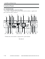
CHAPTER 1 INTRODUCTION
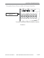
4.1.2 Control Panel for a Fax Model
The machine possesses a single power switch used to turn on or off the machine.
[3]
[1] [2]
[4]
[6]
[8]
[5]
[7]
[10]
[9]
Monitor
COPY
FAX
Directory
[31]
[32]
[30]
F2
[29]
F3
F4
BACK
OK
[27]
[28]
[11]
Coded
Dial
Hook
[14]
[13]
Pause/
Redial
R
[15]
Line/Mail DirectTX
SYSTEM
Special Features
F1
[12]
[25]
[26]
[24]
@.
ABC
1
2
DEF
3
GHI
UKL
MNO
4
5
6
PQRS
TUV
WXYZ
7
8
9
0
#
C
I
ID
[23] [21]
[19] [17]
[22]
[18]
[20]
[16]
F01-401-02
COPYRIGHT© 2002 CANON INC. 2000 CANON iR1600/iR2000/iR1610/iR2010 SERIES REV.0 MAR. 2002
1-21
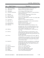
CHAPTER 1 INTRODUCTION
No.
Key/LED name
[1]
[2]
[3]
[4]
[5]
[6]
Counter key
Contrast key
System switch key
Monitor key
Reset key
Numeric keypad
[7]
[8]
[9]
Clear key
Energy Save key
Directory key
[10] Coded Dial key
[11] Hook key
[12] Pause/Redial key
[13] Tone/R key
[14]
[15]
[16]
[17]
[18]
[19]
[20]
[21]
[22]
[23]
Line/Mail key
Direct TX key
One-Touch panel
Stop key
Main Power LED
Start key
ID key
Error indicator
*/# key
Communication Status LED
[24]
[25]
[26]
[27]
[28]
[29]
[30]
Interrupt key
Additional Functions key
OK key
Back key
Screen Select key
Control panel LCD
Special Features key
[31] Copy Short-Cut key
[32] Sort key
1-22
Description
Use it to check the counter status.
Use it to adjust the contrast of the control panel screen.
Use it to switch the system.
Use it to check the communication status.
Use it to use default copy mode settings.
Use it enter a telephone number, number of copies to make, or
the like.
Use it to clear registered items/settings.
Use it to turn off the power save mode.
Use it to call up a destination registered for one-touch or speed
dialing.
Use it to access speed dialing.
Use it to turn on the speaker.
Use it to add a pause in a telephone number. Or, use it to dial
the most recently dialed number.
Use it as the R key on a 230V model; or, as the Tone key on a
120V model.
Use it to select a line.
Use it to start direct transmission.
Use it for one-touch dialing.
Use it to stop an ongoing transmission or copying operation.
Use it to see if the main power is on.
Use it to start a transmission or copying operation.
Use it to make settings in ID mode.
Use it to see if any error has occurred on the printer.
Use it to enter a fax telephone number or F code.
Use it to check access to the HDD (flashing) while the telephone line is in use or to see if memory reception is under way
(remaining on).
Use it to turn on or off interrupt copying.
Use it to bring up the User Mode Settings screen.
Use it to check registered items/settings.
Use it to return to the previous screen.
Use it to select a function indicated on the display.
Use it to bring up various settings screens.
Use it to make settings for special features (page separation,
frame erasing, binding margin, reduced page composition).
Use it to select a registered copy short-cut function (default: 1,
reduce; 2, enlarge; 3, page separate; 4, frame erase).
Use it to turn on sort copy when making copies using an ADF.
COPYRIGHT© 2002 CANON INC. 2000 CANON iR1600/iR2000/iR1610/iR2010 SERIES REV.0 MAR. 2002
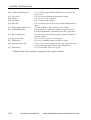
CHAPTER 1 INTRODUCTION
[1]
[2]
[3]
[4]
Delayed
Advanced
Transmission Communication
Memor y
Reception
Transfer
Memor y
Reference
Repor t
TTI Selactor
Stack Bypass
Setting
Stamp
D.T.
Pin Code
[17] [16] [15] [14] [13]
[5] [6]
Tone/+
[7]
Delete
Space
M
+
[12] [11]
OK
Clear
[10]
[9]
[8]
F01-401-03
No.
Key name
[1]
[2]
Delayed Transmission key
Advanced Transmission key
[3]
[4]
[5]
[6]
[7]
[8]
[9]
[10]
[11]
Transfer key
Memory Reception key
Space key
Speaker Volume key
Delete key
OK key
Cursor key
Clear key
+ key (if 120V model);
M key (if UK)
Description
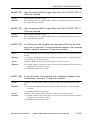
Use it to set a transmission item.
Use it to set an advanced transmission feature (polling, confidential, relay, general-purpose box, F code, password).
Use it to select the transfer function.
Use it to turn on or off the memory reception function.
Use it to add a space to a string of numerals or characters.
Use it to adjust the level of sound from the speaker.
Use it to delete a character input.
Use it to store registered items/settings.
Use it call up or check items/settings.
Use it to delete registered items/settings.
Use it to add the + symbol to a telephone number.
In the U.K., if you wish to use the UK Call, Global Call, and
Day Call, and Day Call Services of Cable and Wireless Communication Ltd., use this key.
COPYRIGHT© 2002 CANON INC. 2000 CANON iR1600/iR2000/iR1610/iR2010 SERIES REV.0 MAR. 2002
1-23
CHAPTER 1 INTRODUCTION
[12] TTI Selector key
Use it to change the name of the sender.
[13] PIN Code key (if 120V model); Use it to select a PIN code.
DTM key (if UK)
Press this key to confirm the dial tone when dialing a number.
(Not used in the UK, Ireland, Hong Kong, Australia, New
Zealand, Singapole, or Malaysia)
[14] Report key
Use it to generate various reports or lists.
[15] Stamp key
Use it to add a stamp to originals to indicate that they have
been read or sent.
[16] Memory Reference key
Use it to check or delete the contents of memory.
[17] Manual Feed Size Select key
Use it to select a manual feed size.
1-24
COPYRIGHT© 2002 CANON INC. 2000 CANON iR1600/iR2000/iR1610/iR2010 SERIES REV.0 MAR. 2002
CHAPTER 1 INTRODUCTION
4.1.3 Master Password
Passwords include those required when changing ore deleting confidential mailboxes,
memory boxes and mailbox settings as well as passwords used for system administrator
information.
The master password, which is used in servicing and when the user has forgotten the
password, is shown below.
The master password is to be used by service engineer only and must not
be disclosed to the user.
Mater password: 0334559769
COPYRIGHT© 2002 CANON INC. 2000 CANON iR1600/iR2000/iR1610/iR2010 SERIES REV.0 MAR. 2002
1-25
CHAPTER 1 INTRODUCTION
4.2 Basic Operation
4.2.1 Basic Operation for a Non-Fax Model
Operate the machine as follows when using its basic functions:
Key to use
Zoom key
Paper Select key
Image Quality key
Light/AE/Dark key
Description
Use it to select a default ratio or a zoom ratio (between 50% an
200%).
Use it to select a cassette as a source of paper.
Use it to select a level of image quality (text, text/photo, photo).
Use it to select a reading density (auto, F1 through F9).
T01-402-01
4.2.2 Basic Operation for a Fax Model
The machine functions as follows in response to a press on the Start key in the control
panel:
Item
Description
ZOOM RATIO
PAPER SELECT
DENSITY
IMAGEQUALITY
Use it to select a default ratio or a zoom ratio (between 50% an
200%).
Use it to select a cassette as a source of paper.
Use it to select a level of image quality (text, text/photo, photo).
Use it to select a reading density (auto, F1 through F9).
T01-402-02
1-26
COPYRIGHT© 2002 CANON INC. 2000 CANON iR1600/iR2000/iR1610/iR2010 SERIES REV.0 MAR. 2002
CHAPTER 1 INTRODUCTION
4.3 Extended Operation
4.3.1 Extended Operation for a Non-Fax Model
Press the Special Features key in the control panel to make use of the following functions:
Items
Description
2PG SET SETTING
Use it to select page separation in book mode (to copy left and right
pages of spread book); specify open on left or right and original
size.
MARGIN SETTING
Use it to create a binding margin on paper. Specify the location of
margin (left, right, top, bottom) and the margin width (1 to 20 mm).
FRAME ERASE SETTING
Use it to specify the location of frame erasing.
DOC. FRAME ERASE Use it to select frame erasing of the original.
BOOK FRAME ERASE Use it to delete images of the sides and middle binding width of the
original (e.g., book).
HOLE PUNCH ERASE Use it to delete the image, if any, of holes in the original (on the left
side) so that the copies will not show them.
2 ON 1 SETTING
Use it to enter an original size and paper size.
T01-403-01
4.3.2 Extended Operation for a Fax Model
Press the Special Features key in the control panel to make use of the following functions:
Items
2-PG SEP
MARGIN
FRAME ERASE
FRAME ERASE
BOOK FR ERS
P/HOLE ERASE
LAYOUT COPY
Description
Use it to select page separation in book mode (to copy left and right
pages of spread book); specify open on left or right and original
size.
Use it to create a binding margin on paper. Specify the location of
margin (left, right, top, bottom) and the margin width (1 to 20 mm).
Use it to specify the location of frame erasing.
Use it to select frame erasing of the original.
Use it to delete images of the sides and middle binding width of the
original (e.g., book).
Use it to delete the image, if any, of holes in the original (on the left
side) so that the copies will not show them.
Use it to enter an original size and paper size; then to select 2-on-1
or 4-on-1 copying mode.
T01-403-02
COPYRIGHT© 2002 CANON INC. 2000 CANON iR1600/iR2000/iR1610/iR2010 SERIES REV.0 MAR. 2002
1-27
CHAPTER 1 INTRODUCTION
4.4 User Mode
4.4.1 User Mode for a Non-Fax Model
A press on the Additional Functions key in the control panel will bring up the User
Mode settings screen.
The user mode is structureed as follows:
Additional Functions key pressed
COMMON SETTING
COPY SETTING
TIMER SETTING
SYSTEM SETTING
ADJUST SETTING
PRINT LISTS
For sub items, see the pages that follow.
1-28
COPYRIGHT© 2002 CANON INC. 2000 CANON iR1600/iR2000/iR1610/iR2010 SERIES REV.0 MAR. 2002
CHAPTER 1 INTRODUCTION
COMMON SETTINGS
VOLUME
CONTROL
*, The notation within brackets <> indicates factory settings.
KEYPAD VOLUME
ALARM VOLUME
PRINTING END
TONE
SACANNING END
TONE
ESS POWER
LEVEL
ON*
(1-3)
OFF
ON*
(1-3)
OFF
ON*
(1-3)
ERROR (1-3)
ONLY*
OFF
ON*
(1-3)
ERROR (1-3)
ONLY*
OFF
LOW*
HIGH
COPYRIGHT© 2002 CANON INC. 2000 CANON iR1600/iR2000/iR1610/iR2010 SERIES REV.0 MAR. 2002
1-29
CHAPTER 1 INTRODUCTION
CASS. ELIGIBLTY
COPY
STACK BYPASS
CASSETTE1
*1
CASSETTE2
*2
CASSETTE3
CASSETTE4
REPORT
STACK BYPASS
CASSETTE1
*1
CASSETTE2
*2
CASSETTE3
CASSETTE4
ON
STACK
BYPASS SIZE
OFF*
ON*
OFF
ON*
OFF
ON*
OFF
ON*
OFF
ON
OFF*
ON*
OFF
ON*
OFF
ON*
OFF
ON*
OFF
STACK
BYPASS SIZE
A3
A4
B4
B5
A4R
A5
B5R
A5R
11 x 17
LTR
LTRR
LGL
STMT
STMTR
A3
A4
B4
B5
A4R
A5
B5R
A5R
11 x 17
LTR
LTRR
LGL
STMT
STMTR
*1 : Enabled for the iR1600 and if equipped with a 1-/3-cassette unit.
*2 : Enabled for the iR2000 and if equipped with a 2-cassette unit.
1-30
COPYRIGHT© 2002 CANON INC. 2000 CANON iR1600/iR2000/iR1610/iR2010 SERIES REV.0 MAR. 2002
CHAPTER 1 INTRODUCTION
USE STACK BYPASS
ON
OFF*
SELECT PAPER
PLAIN PAPER*
HEAVY PAPER
ROTATE PRINT
ON*
OFF
TRAY SETTINGS
TRAYA*
COPY
PRINTER
TRAYB
COPY
PRINTER
DISPLAY
LANGUAGE
ENGLISH
FRENCH
SPANISH
GERMAN
ITALIAN
DUTCH
FINNISH
PORTUGUESE
STACK
BYPASS SIZE
ON*
OFF
ON*
OFF
ON*
OFF
ON*
OFF
A3
A4
B4
B5
A4R
A5
B5R
A5R
11 x 17
LTR
LTRR
LGL
STMT
STMTR
*1
NORWEGINA
SWEDISH
DANISH
SLOVENE
CZECH
HUNGARIAN
RUSSIAN
*1 : Enabled only when an inner 2-way tray is installed.
COPYRIGHT© 2002 CANON INC. 2000 CANON iR1600/iR2000/iR1610/iR2010 SERIES REV.0 MAR. 2002
1-31
CHAPTER 1 INTRODUCTION
COPY SETTINGS
STANDARD
EXPOSURE
MANUAL (1-9)
AUTO
STD ZOOM RATIO
50-200% <100%>
STANDARD COPY QTY
1-99 <1>
FRAME ERASE WIDTH
1-20MM <2MM>
AUTO SORT
ON*
OFF
SORT ROTATE
ON*
OFF
SHARPNESS
1-9 <5>
PRESCAN
1-32
ON*
OFF
COPYRIGHT© 2002 CANON INC. 2000 CANON iR1600/iR2000/iR1610/iR2010 SERIES REV.0 MAR. 2002
CHAPTER 1 INTRODUCTION
TEIMER SETTINGS
DATA / TIME SETTING
AUTO CLEAR
ENERGY SAVER
DAILY TIMER SET
DATE SET UP
00/00 ’ 00 00:00 (INPUT DATE AND TIME)
ON*
AUTO CLEAR TIME (1-9MIN.) <2MIN.>
OFF
ON
ENERGY SVR TIME (03-30MIN.) <15MIN.>
OFF*
SUN to SAT
00:00 (INPUT TIME)
YYYY MM/DD*
MM/DD YYYY
DD/MM YYYY
COPYRIGHT© 2002 CANON INC. 2000 CANON iR1600/iR2000/iR1610/iR2010 SERIES REV.0 MAR. 2002
1-33
CHAPTER 1 INTRODUCTION
SYSTEM SETTINGS
SYS. ADMIN. INFO
SYS. ADMIN. ID
SYSTEM PASSWORD
DEPT. ID
MANAGEMENT
ON
OFF*
DEPT ID ENTRY
INPUT DEPT. ID
(01-99)
COUNT
MANAGEMENT
COUNT INFORMATION
COUNT RESET
ON
OFF
PRINT LIMITS
ON
OFF*
RESTRICTIONS
PRIN WITH NO ID
NETWORK SETTIGS
ON*
OFF
IP ADDRESS
AUTO
INPUT ID
INPUT PASSWORD
PASSWORD
INPUT PASSWORD
COPY LIMITS INPUT COPY LIMITS
PRINT COUNT
DIPLAY PRINT
COUNT
*1
AUTO
FIXED
IP ADDRESS
SUBNET MASK
DEFAULT GATEWAY
DNS SERVER ADD
DNS DYNAMIC SET
HOST NAME
DOMAIN NAME
VIEW IP ADDRESS
DHCP
ON
OFF
BOOTP
ON
OFF
RAAP
ON
OFF
INPUT ADDRESS
INPUT ADDRESS
INPUT ADDRESS
INPUT ADDRESS
ON
OFF
INPUT ADDRESS
INPUT ADDRESS
*1 : Enabled only when a network printer function is used.
1-34
COPYRIGHT© 2002 CANON INC. 2000 CANON iR1600/iR2000/iR1610/iR2010 SERIES REV.0 MAR. 2002
CHAPTER 1 INTRODUCTION
ADJUST/CLEAN
ROLLER CLEANING
USE STAPLE/SHIFT
START CLEANING
CLEAN PAPER PRT
ON
OFF* *1
*1 : Enabled only when a finisher is installed.
PRINT LISTS
USER DATA
DEPT. INFO LIST
CANCEL REPORT
COPYRIGHT© 2002 CANON INC. 2000 CANON iR1600/iR2000/iR1610/iR2010 SERIES REV.0 MAR. 2002
1-35
CHAPTER 1 INTRODUCTION
4.4.2 User Mode for a Fax Model
A press on the Additional Functions key in the control panel will bring up the User
Mode setting screen.
The user mode is structured as followes:
Additional Functions key preesed
COMMON SETTIGS
COPY SETTINGS
FAX SETTINGS
ADD. REGISTRATION
TIMER SETTINGS
SYSETM SETTINGS
ADJUST/CLEAN
PRINT LISTS
For sub items, see the pages that follow.
1-36
COPYRIGHT© 2002 CANON INC. 2000 CANON iR1600/iR2000/iR1610/iR2010 SERIES REV.0 MAR. 2002
CHAPTER 1 INTRODUCTION
COMMON SETTINGS
*,The notation within brackets<> indcates factory settings.
DEFALT SETTINGS
SW AFTER
AUTO CLEAR
VOLUME
CONTROL
COPY*
FAX
RETURN TO DEFAULT*
DO NOT RTN TO DFLT
KEYPAD VOLUME
ALARM VOLUME
TX DONE TONE
RX DONE TONE
PRINTING DONE
TONE
SCANNING DONE
TONE
ESS POWER
LEVEL
ON*
OFF
ON*
OFF
ON
ERROR ONLY*
OFF
ON
ERROR ONLY*
OFF
ON
ERROR ONLY*
OFF
ON
ERROR ONLY*
OFF
(1-3)
(1-3)
(1-3)
(1-3)
(1-3)
(1-3)
(1-3)
(1-3)
(1-3)
(1-3)
LOW*
HIGH
COPYRIGHT© 2002 CANON INC. 2000 CANON iR1600/iR2000/iR1610/iR2010 SERIES REV.0 MAR. 2002
1-37
CHAPTER 1 INTRODUCTION
DRAWER
ELIGIGIBLY
COPY
STACK BYPASS
DRAWER 1
*1
DRAWER 2
*2
DRAWER 3
DRAWER 4
FAX
RECEIVING
STACK BYPASS
DRAWER 1
*1
DRAWER 2
*2
DRAWER 3
DRAWER 4
REPORT
STACK BYPASS
DRAWER 1
*1
DRAWER 2
*2
DRAWER 3
DRAWER 4
ON
STACK BYPASS
SIZE
OFF*
ON*
OFF
ON*
OFF
ON*
OFF
ON*
OFF
ON
STACK BYPASS
SIZE
OFF*
ON*
OFF
ON*
OFF
ON*
OFF
ON*
OFF
ON
STACK BYPASS
SIZE
OFF*
ON*
OFF
ON*
OFF
ON*
OFF
ON*
OFF
A3
A4
B4
B5
A4R
A5
B5R
A5R
11X17
LTR
LTRR
LGL
STMT
STMTR
A3
A4
B4
B5
A4R
A5
B5R
A5R
11X17
LTR
LTRR
LGL
STMT
STMTR
A3
A4
B4
B5
A4R
A5
B5R
A5R
11X17
LTR
LTRR
LGL
STMT
STMTR
*1: Enabled for the 16cpm models if equipped with a 1-/3-cassette unit.
*2: Enabled for the 20cpm models if equipped with a 2-cassette unit.
1-38
COPYRIGHT© 2002 CANON INC. 2000 CANON iR1600/iR2000/iR1610/iR2010 SERIES REV.0 MAR. 2002
CHAPTER 1 INTRODUCTION
USE STACK
BYPASS
ON
STACK BYPASS
SIZE
OFF*
SELECT PAPER
PLAIN PAPER*
HEAVY PAPER
ROTATE PRINT
ON*
OFF
TRAYA*
TRAY SETTINGS
COPY
FAX
PRINTER
TRAYB
COPY
FAX
PRINTER
DISPLAY
LANGUAGE
ENGLISH
FRENCH
SPANISH
GERMAN
ITALIAN
DUTCH
FINNISH
PRTUGUESE
A3
A4
B4
B5
A4R
A5
B5R
A5R
11X17
LTR
LTRR
LGL
STMT
STMTR
ON*
OFF
ON*
OFF
ON*
OFF
ON*
OFF
ON*
OFF
ON*
OFF
*1
NORWEGIAN
SWEDISH
DANISH
SLOVENE
CZECH
HUNGARIAN
RUSSIAN
*1: Enabled only when an inner 2-way tray is installed.
COPYRIGHT© 2002 CANON INC. 2000 CANON iR1600/iR2000/iR1610/iR2010 SERIES REV.0 MAR. 2002
1-39
CHAPTER 1 INTRODUCTION
COPY SETTINGS
STD IMAGE
QUAL/EXP
IMAGE QUALITY
DENSITY SETTINGS
TEXT
TEXT/PHOTO
HALFTONE
1-9
AUTO EXPOSURE
STD ZOOM RATTIO
50-200%<100%>
STANDARD COPY QTY
1-99COPIES<1COPIES>
FRAME ERASE WIDTH
1-20mm<2mm>
AUTO SORT
ON*
OFF
SORT
ON*
*1
ROTATE
OFF
SHORTCUT KEY
SHORT CUT
REDUCE*
SET
KEY (1-4)
ENLARGE*
DIRECT 100%
SHARPNESS
1-9<5>
AUTO ZOOM
PRESCAN
ON*
DARK
OFF
LIGHT
AUTO EXPOSURE
MARGIN
FRAME ERASE*
2-PAGE SEP*
LAYOUT COPY
STAPLE SORT
USE STACK BYPASS
DIF SIZE DOC
*1: FEnables only with expansion memory installed if equipped with a finisher.
1-40
COPYRIGHT© 2002 CANON INC. 2000 CANON iR1600/iR2000/iR1610/iR2010 SERIES REV.0 MAR. 2002
CHAPTER 1 INTRODUCTION
FAX SETTINGS
USER SETTINGS
TEL LINE
SETTINGS
LINE SELECT*1
USER TEL NO.
TEL NO. INPUT
TEL LINE TYPE
TOUCH TONE
ROTARY PULSE*
TX START SPEED
14400bps
9600bps
7200bps
2400bps
33600bps*
14400bps
9600bps
7200bps
2400bps
33600bps*
RX START SPEED
UNIT NAME
NAME INPUT
SENDER NAME
SELECT SENDERS
NAME
SENDER NAME
REG.
PERSONAL
SETTINGS
SENDERE FAX
USER TEL NUMBER*
NUMBER
OTHER FAX NUMBERS
MAIL ACCONUT*2
NAME INPUT
NUMBER INPUT
*1:If the G3 expansion kit is installed, the line1/line2 is dipalyed.
*2:Enabled only when an network inteface board is installed.
COPYRIGHT© 2002 CANON INC. 2000 CANON iR1600/iR2000/iR1610/iR2010 SERIES REV.0 MAR. 2002
1-41
CHAPTER 1 INTRODUCTION
TX TERMINAL ID
SENDER FAX NEMBER
ON
OFF
TTIPOSITION
OUTSIDE IMAGE
INSIDE IMAGE
TEL NEMBER MARK
FAX
TEL
USER TEL NUMBER
OTHER FAX NUMBERS
UNIT TEL NUMBER INPUT
DENSITY CONTROL
LIGHT (1-4)
STANDARD (4-6)
DARK (6-9)
PROG 1-TOUCH KEY
SELECT THE TEL NUMBER
(1-63)
DO NOT USE
USE
TX LINE SELECTION*1
R-KEY SETTING
PSTN
PBX
REPORT SETTINGS
TX REPORT
OUTPUT NO
PRINT ERROR ONLY*
ON
OFF
ON
OFF
OUTPUT YES
PX REPORT
CONFID.RX REPORT
ACTIVITY REPORT
OUTPUT NO*
PRINT ERROR ONLY
OUTPUT YES
OUTPUT NO
OUTPUT YES*
AUTO PRINT
DAILY REPORT
TX/RX SEPARETE
ON*
OFF
OFF*
ON
OFF*
ON
PRINT TIME SETTING
*1:displayed only when the G3 expansion kit is installed.
1-42
COPYRIGHT© 2002 CANON INC. 2000 CANON iR1600/iR2000/iR1610/iR2010 SERIES REV.0 MAR. 2002
CHAPTER 1 INTRODUCTION
TX SETTINGS
ON*
OFF
PAUSE TIME
01-15SEC <02>
*
AUTO REDIAL ON
REDIAL TIMES 01-15TIMES
REDIAL INTERVAL 02-99MIN
TX ERROR RESEND
ECM TX
<02>
<02>
ON*
OFF
ALL PAGES
ERROR & 1ST PAGE*
ERROR PAGE
OFF
ERASE FAILED TX
TIME OUT
STAMP ACTION
TX ROTATION
ON*
OFF
ON*
OFF
DIRECT & MEMORY TX*
DIRECT TX
ON*
OFF
RX SETTINGS
ECM RX
RX PAGE FOOTER
2 ON 1
ON*
OFF
ON
OFF*
ON
OFF*
COPYRIGHT© 2002 CANON INC. 2000 CANON iR1600/iR2000/iR1610/iR2010 SERIES REV.0 MAR. 2002
1-43
CHAPTER 1 INTRODUCTION
PRINTER SETTINGS
# OF RX COPIES
SELECT DRAWER
RX
ON*
REDUCTIUON
OFF
TONER SUPPLYLOW
1-44
01-99COPIES
DRAWER SW A
ON*
OFF
DRAWER SW B
ON*
OFF
DRAWER SW C
ON*
OFF
DRAWER SW D
ON*
OFF
RX REDUCTION
AUTO SELECTION*
FIXED
97%
REDUCTION 95%
90%*
75%
SLECT REDUCTION
VERTICAL ONLY*
DIR
HORIZ & VERTICAL
RX TO MEMORY
KEEP PRINTING*
COPYRIGHT© 2002 CANON INC. 2000 CANON iR1600/iR2000/iR1610/iR2010 SERIES REV.0 MAR. 2002
CHAPTER 1 INTRODUCTION
FILE SETTINGS
CONFIDNT MAILBOX
SETUP FILE
SET BOX NO.
TO A
CHANGE DATA
FROM A
FILE NAME
PASSWORD
SUBADDRESS
RX PASSWORD
# OF RX COPIES
DELETE FILE
SET BOX NO.*1
TO A
BOX NAME INPUT
ID NUMBER INPUT
SUBADDRESS INPUT
PASSWORD INPUT
NUMBER INPUT OF RX COPIES
SET BOX NO.*1
BOX NUMBER INPUT
RELAY TX GROUP SETUP FILE*1
SET RLY TX GROUP
NUMBER
TO B
TO B
CHANGE DATA
SET BOX NO.*1
FROM B
GROUP DIAL NAME
BOX NAME INPUT
PASSWORD
ID NUMBER INPUT
TRIGGER
SUBADDRESS
SUBADDRESS INPUT
SENDER’ FAX NO.
SELECT THE OTHER PARTY
*2
MAIL ADDRESS (To)
SPECIFY THE MAIL ADDRESS
RX PASWORD
PASSWORD INPUT
SELECT ORIG
ON*
SELECT THE DESTINATION
UNIT
OFF
PRINT RX DOC.
ON
NUMBER OF
NUMBER INPUT
RX COPIES
(01-99COPIES)
*
OFF
SELECT LOCATIONS
SPECIFY THE DESTINATION
*
TX REPORT
TRANSMIT
NOT TRANSMIT
TX STRAT TIME
TIME SELECT (1-5)
TIME INPUT
RELAY B’ CAST
ON *
SET RLY TX
NUMBER INPUT
OFF
GROUP NUMBER
DELETE FILE
SET BOX NO.
*1: If the password is set, enter the password.
*2: Enabled only when an network inteface board is installed.
COPYRIGHT© 2002 CANON INC. 2000 CANON iR1600/iR2000/iR1610/iR2010 SERIES REV.0 MAR. 2002
1-45
CHAPTER 1 INTRODUCTION
PRESET POLLING
SET BOX NO.*1
TO A
CHANGE DATA
SET BOX NO.*1
TO A
DELETE DATA
FROM A
FILE NAME
PASSWORD
SELECT LOCATIONS
START TIME
SET BOX NO.*1
BOX NAME INPUT
ID NUMBER INPUT
SPECIFY THE DESTINATION
EVERY BODY
SELECT THE MEMORY NUMABER (1-5)
TIME INPUT
SELECT DAYS
SELECT DAYS (SUN to SAT)
SELECT THE MEMORY NUMABER (1-5)
TIME INPUT
POLLING BOX
SETUP FILEBOX
NUMBER INPUT
CHANGE DATA
SET BOX NO.*1
TO B
DELETE DATA
FROM B
FILE NAME
PASSWORD
SBADDRESS
TA PAAWORD
ERASE AFTER TX
TO B
SET BOX NO.*1
BOX NAME INPUT
ID NUMBER INPUT
SUBADDRESS INPUT
PASSWORD INPUT
ON*
OFF
*1: If the password is set, enter the password.
1-46
COPYRIGHT© 2002 CANON INC. 2000 CANON iR1600/iR2000/iR1610/iR2010 SERIES REV.0 MAR. 2002
CHAPTER 1 INTRODUCTION
POLLING BOX
SET BOX NO.*1
TO A
CHANGE DATA
SET BOX NO.*1
TO A
*1
DELETE DATA
SET BOX NO.
FROM A
FILE NAME
BOX NAME INPUT
PASSWORD
PASSWORD INPUT
SBADDRESS
SUBADDRESS INPUT
TA PAAWORD
PASSWORD INPUT
ERASE AFTER TX
ON*
OFF
TRANSFER
SETUP FILE BOX NUMBER INPUT
TO B
CHANGE DATA SET BOX NO.*1
TO B
*1
DELETE DATA SET BOX NO.
FROM B
FILE NAME
BOX NAME INPUT
SELECT LOCATIONS SPECIFY THE DESTINATION
PASSWORD
ID NUMBER INPUT
SELECT ORIG
ON
SPECIFY THE DESTINATION
*
UNIT
OFF
TIME SETUP
START TIME
TO C
END TIME
TO C
FROM C
EVERYDAY
PRINT RX DOC
SELECT THE MEMORY
NUMABER (1-5)
SELECT DAYS (SUN to SAT)
TIME INPUT
SELECT THE MEMORY
NUMBER (1-5)
ON
RX COPIES
*
OFF
TIME INPUT
COPIES INPUT
(01-99COPIES)
*1: If the password is set, enter the password.
COPYRIGHT© 2002 CANON INC. 2000 CANON iR1600/iR2000/iR1610/iR2010 SERIES REV.0 MAR. 2002
1-47
CHAPTER 1 INTRODUCTION
SYSTEM SETTINGS
MEMORY LOCK RX
ON
OFF*
MEM LOCK PASSWORD
REPORT
OUTPUT YES
OUTPUT NO*
TIME SETUP OFF*
ON
START TIME
ID NUMBER INPUT
EVERYDAY
SELECT THE MEMORY NUMABER (1-5)
TIME INPUT
SELECT DAYS (SUN to SAT)
END TIME
SELECT THE MEMORY NUMBER (1-5)
TIME INPUT
EVERYDAY
SELECT THE MEMORY NUMABER (1-5)
TIME INPUT
SELECT DAYS to SUN (SAT)
SELECT THE MEMORY NUMBER (1-5)
TIME INPUT
RX PASSWORD
PHONE NO CHECK
1-48
PASSWORD INPUT(20 DIGITS)
ON
OFF*
COPYRIGHT© 2002 CANON INC. 2000 CANON iR1600/iR2000/iR1610/iR2010 SERIES REV.0 MAR. 2002
CHAPTER 1 INTRODUCTION
FAX DEFAULT
RESOLUTION
OFF*
STANDARD
FINE
SUPER FINE
ULTRA FINE
SCAN DESITTY
OFF*
LIGHT
STANDARD
DARK
OFF*
TEXT
TEX/PHOTO
PHOTO
IMAGE QUALITY
BOOK TX SCAN
SIZE
TX MODE
TX STAMP
ACCESS CODE
USE
SHEET*
A3
B4
A4
B5
A5
MEMORY SENDING*
DIRECT SENDING
TX STAMP OFF
TX STAMP ON
ACCESS CODE KEY
USING # KEY*
OTHER
NO OF CHARACTERS
(2-5CHARACTER)
DO NOT USE*
RX RESTRICTION
OFF*
ON
WITH SENDER INFO
REGSTERED SENDER
COPYRIGHT© 2002 CANON INC. 2000 CANON iR1600/iR2000/iR1610/iR2010 SERIES REV.0 MAR. 2002
1-49
CHAPTER 1 INTRODUCTION
LAN SETTINGS*1
SMTP SERVER
POP3 SERVER
EMAIL RX PROTOCOL
POP CHECK INTERVAL
RETRY
RETRY INTERVAL
TIME ZONE
PORT NO.
MAX. RX DATA SIZE
TX MODE
RX TEXT PRINT
LARGE MAIL
ERROR MAIL
ADDRESS FORMAT
PRINT MAIL HEADER
MAIL USER SETTINGS
SERVER NAME INPUT
SERVER NAME INPUT
SMTP
POP3*
(000-060 MIN.) <030>
(00-05 TIMES) <02>
(01-60 MIN.) <02>
GMT -12-+12 <+09>
SMTP TX
POP3 RX
SMTP TX
SIZE INPUT
SIMPLE MODE
E-MAIL MODE
NUMBER INPUT
NUMBER INPUT
NUMBER INPUT
PDF*
TIFF (MMR)
TIFF (MR)
TIFF (MH)
ON
AUTO*
OFF
LEAVE ON SERVER*
ERASE FROM SERVER
LEAVE ON SERVER*
ERASE FROM SERVER
NAME<ADDRESS>*
ADDRESS(NAME)
ADDRESS
OFF*
ON
*1:Enabled only when an network inteface board is installed.
1-50
COPYRIGHT© 2002 CANON INC. 2000 CANON iR1600/iR2000/iR1610/iR2010 SERIES REV.0 MAR. 2002
CHAPTER 1 INTRODUCTION
MAIL ADD SETTINGS
SELCT THE MAIL ACCOUNT
MAIL ADD. (From)
NAME INPUT
OPTIONAL
SETTING
E-MAIL ADDRESS INPUT
REPLAY ADDRESS
ADDRESS INPUT
SUBJECT
AUTO LINE
WRAP
AUTO*
FIXED
SUBJECT INPUT
ON
MESSEGE TEXT
*
OFF
INPUT
ON
SIGNATURE
*
OFF
INPUT
HIGH
STANDARD*
LOW
ON
OFF*
ON*
CHARACTERS
OFF
INPUT
POP3 ACCOUNT
POP3 PASSSWORD
ACCOUNT INPUT
PASSWORD INPUT
MESSEGE TEXT
SIGNATURE
PRIORITY
RX CONFIRMATION
POP3 SETTINGS
SMTP SETTINGS
COPYRIGHT© 2002 CANON INC. 2000 CANON iR1600/iR2000/iR1610/iR2010 SERIES REV.0 MAR. 2002
1-51
CHAPTER 1 INTRODUCTION
ADD. REGSTRATION
1-TOUCH SPD DIAL
CODED SPD DIAL
FROM A
TEL# REGISTRATION
TEL NUMBER ENTRY
NAME
OPTIONAL
SETTING
ACCESS CODE
TX TIME SETTING
TX TYPE
INTERNATIONAL
TX SPEED
TX LINE
SELECTION*1
SENDER NAME
TO A
TO A
SELECT THE MEMORY NUMBER
TEL NUMBER INPUT
NAME INPUT
ON
OFF*
ACCESS CODE INPUT
SELECT THE MEMORY NUMBER
REGULAR TX
COFIDENSIAL
PASSWORD
TX
SUBADDRESS
ORIG RELAY
PASSWORD
TX
SUBADDRESS
SBADDRESS
PASSWORD
TX
SUBADDRESS
POLLING
PASSWORD
TX
SUBADDRESS
TX TIME INPUT
PASSWORD INPUT
PASSWORD INPUT
PASSWORD INPUT
PASSWORD INPUT
DOMESTIC*
INTERNATIONAL (1)
INTERNATIONAL (2)
INTERNATIONAL (3)
33600bps*
14400bps
9600bps
4800bps
AUTO*
FIXED
SELECT THE SENDERS NAME
*1:Enables only when the G3 expansion kit is installed.
1-52
COPYRIGHT© 2002 CANON INC. 2000 CANON iR1600/iR2000/iR1610/iR2010 SERIES REV.0 MAR. 2002
CHAPTER 1 INTRODUCTION
E-MAIL ADDRESS
SELECT THE MEMORY NUMBER
ENTER E-MAIL ADD
NAME
E-MAIL ADDRESS INPUT
NAME INPUT
OPTICAL
SETTINGS
ON*
OFF
ACCESS CODE
TX MODE
ACCESS CODE INPUT
SIMPLE MODE
E-MAILMODE
PDF*
TIFF (MMR)
TIFF (MR)
TIFF (MH)
TX TIME SETTING
SENDER NAME
FTPSERVER*1
AUTO*
FIXED
FILE NAME INPUT
SELECT THE MEMORY NUMBER
TX TIME INPUT
SELECT SENDERS NAME
SELECT THE MEMORY NUMBER
FTP SERVER NAME
NAME
SERVER NAME INPUT
NAME INPUT
LOGON NAME
PASSWORD
UPLOAD DEIRECTORY
OPTIONAL
SETTING
LOGIN NAME INPUT
PASSWORD INPUT
DIRECTORY NAME INPUT
ON*
OFF
ACCESS CODE
PUT FILE NAME
ACCESS CODE INPUT
AUTO*
FIXED
FILE NAME INPUT
*
PDF
TIFF (MMR)
TIFF (MR)
TIFF (MH)
TX FILE NAME
REPORT WITH
TX IMAGE
*1:Enables only when an network interface board is installed.
COPYRIGHT© 2002 CANON INC. 2000 CANON iR1600/iR2000/iR1610/iR2010 SERIES REV.0 MAR. 2002
1-53
CHAPTER 1 INTRODUCTION
CONTROL POR NO.
USE CONTROL FILE
TX TIME SETTING
SENDING NAME
GROUP DIAL
1-54
PORY NUMBER INPUT
ON
AUTO
*
FIXED
OFF
FILE NAME INPUT
SELECT THE MEMORY NUMBER
SELECT THE SENDERS NAME
TIME INPUT
SELECT THE MEMORY NUMBER
DESTINATION TEL/ID
NAME
SPECIFY THE DESTINATION
NAME INPUT
OPTIONAL SETTING
ON
OFF*
ACCESS CODE
TX TIME SETTING
ACCESS CODE INPUT
SELECT THE MEMORY NUMBER
TIME INPUT
COPYRIGHT© 2002 CANON INC. 2000 CANON iR1600/iR2000/iR1610/iR2010 SERIES REV.0 MAR. 2002
CHAPTER 1 INTRODUCTION
TIMER SETTINGS
DATE/TIME SETTING
AUTO CLEAR
ENERGY SAVER
DAILY TIMER SET
DATE SETUP
*
ON
OFF
ON*
OFF
DATE/TIME INPUT
AUTO CLEAR TIME (1 to 9MIN.) <2MIN.>
ENERGY SAVE TIMEINPUT
(03-30MIN.) <15MIN.>
SUN TO SAT
TIME INPUT
*
YYYY MM/DD
MM/DD YYYY
DD/MM YYYY
COPYRIGHT© 2002 CANON INC. 2000 CANON iR1600/iR2000/iR1610/iR2010 SERIES REV.0 MAR. 2002
1-55
CHAPTER 1 INTRODUCTION
SYSTEM SETTINGS
SYS. ADMIN. INFO
DEPT. ID
MANAGEMENT
DEPT ID ENTRY
COUNT
MANAGEMENT
RESTRICTIONS
PRIN WITH NO ID
NETWORK SETTIGS
SYS. ADMIN. ID
SYSTEM PASSWORD
ON
OFF*
INPUT DEPT. ID
(01-99)
DEPT ID INPUT
SYSTEM PASSWORD INPUT
PASSWORD
INPUT PASSWORD
COPY LIMITS
INPUT COPY LIMITS
TX LIMITS
INPUT TX LIMITS
SELECT SENDER
COUNT
PRINT COUNT
INFORMATION
COUNT RESET ON TX/RA PAGE
OFF COUNT
PRINT LIMITS ON
OFF*
RESTRICT TX
ON
OFF*
ON*
OFF
*1
IP ADDRESS
AUTO
AUTO
FIXED
IP ADDRESS
SUBNET MASK
DEFAULT GATEWAY
DNS SERVER ADD
DNS DYNAMIC SET
HOST NAME
DMAIN NAME
VIEW IP ADDRESS
DIPLAY PRINT
COUNT
DIPLAY PAGE
COUNT
DHCP
ON
OFF
BOOTP
ON
OFF
RAAP
ON
OFF
INPUT ADDRESS
INPUT ADDRESS
INPUT ADDRESS
INPUT ADDRESS
ON
OFF
INPUT ADDRESS
INPUT ADDRESS
DISPLAY IP ADDRESS
*1:Enabled only when an network inteface board is installed.
1-56
COPYRIGHT© 2002 CANON INC. 2000 CANON iR1600/iR2000/iR1610/iR2010 SERIES REV.0 MAR. 2002
CHAPTER 1 INTRODUCTION
AJUST/CLEAN
ROLLER CLEANING
START CLEANING
CLEAN PAPER PRT
USE STAPLE/SHIFT F
ON
OFF*
*1
*1:Enabled only when an finisher is installed.
COPYRIGHT© 2002 CANON INC. 2000 CANON iR1600/iR2000/iR1610/iR2010 SERIES REV.0 MAR. 2002
1-57
CHAPTER 1 INTRODUCTION
PRINT LISTS
USER DATA
ADDRESS LIST
1-TOUCH LIST1
CODED DIAL LIST1
1-TOUCH LIST12
CODED DIAL LIST2
SORT
NO SORT*
SORT
NO SORT*
SORT
NO SORT*
SORT
NO SORT*
GROUP DIAL LIST
ACCESS CODE LIST
DEPT. INFO LIST
CANCEL LIST
1-58
COPYRIGHT© 2002 CANON INC. 2000 CANON iR1600/iR2000/iR1610/iR2010 SERIES REV.0 MAR. 2002
CHAPTER 1 INTRODUCTION
5 Cleaning by the User
5.1 Cleaning by the User
Instruct the user to provide the following maintenance on a regular basis, including the
cleaning of the following once a month:
· Fixing roller
· Copyboard glass, reading glass, and copyboard cover
5.1.1 Cleaning the Fixing Roller
Advise the user to clean the fixing roller for the following:
· when the cartridge has been replaced.
· when black lines appear on printed paper.
To clean, go through the following:
1) Place A4 or LTR paper in the cassette or manual feed tray.
2) Press the Additional Functions key to bring up the User Mode screen.
3) Using the cursor key, select “5. ADJUST/CLEAN”, and press the OK key.
4) Using the cursor key, select “02 CLEAN PAPER PRT”, and press the OK key so that
the paper will automatically be picked up and the following output will be generated:
F01-501-01
COPYRIGHT© 2002 CANON INC. 2000 CANON iR1600/iR2000/iR1610/iR2010 SERIES REV.0 MAR. 2002
1-59
CHAPTER 1 INTRODUCTION
5) Paying attention to the orientation of the output, place it as shown.
F01-501-02
6) Go though steps 2) through 3), and select “01 START CLEANING” using the cursor
key; then press the OK key so that the cleaning paper will automatically be picked up
and the fixing roller will be cleaned.
Memo
It takes about 3 min between when cleaning starts and when the cleaning
paper is delivered to the delivery tray.
7) See that the cleaning paper has been delivered, indicating the end of cleaning.
1-60
COPYRIGHT© 2002 CANON INC. 2000 CANON iR1600/iR2000/iR1610/iR2010 SERIES REV.0 MAR. 2002
CHAPTER 1 INTRODUCTION
5.1.2 Cleaning the Copyboard Glass, Reading Glass, and Copyboard Cover
White Plate
1) Clean the copyboard over white plate [1], copyboard glass [2], and reading glass [3]
with a cloth moistened with water (well wrung); then, dry wipe them.
[1]
[3]
[2]
F01-501-03
COPYRIGHT© 2002 CANON INC. 2000 CANON iR1600/iR2000/iR1610/iR2010 SERIES REV.0 MAR. 2002
1-61
CHAPTER 1 INTRODUCTION
5.1.3 Cleaning the ADF Roller/Guide Assembly
Advise the user to clean the ADF roller/film assembly for the following in addition to
doing so as part of routine maintenance:
• The cartridge has been replaced.
• The paper printout is soiled.
1) Open the feeder cover of the ADF, and clean the 5 rollers [1] and the separation plate
[2] with a moist cloth (moistened with water and then wrung well).
[1]
[2]
F01-501-04
2) Picking the tab [3] at the front, open the middle cover [4]; then, clean the guide assembly [5] with a moist cloth.
[5]
[3]
[4]
F01-501-05
1-62
COPYRIGHT© 2002 CANON INC. 2000 CANON iR1600/iR2000/iR1610/iR2010 SERIES REV.0 MAR. 2002
CHAPTER 1 INTRODUCTION
3) Close the middle cover and the feeder cover.
4) Open the ADF, and clean the original feed roller [6] (platen roller) with a moist cloth
(moistened with water and then wrung well).
[6]
F01-501-06
5) Close the ADF.
COPYRIGHT© 2002 CANON INC. 2000 CANON iR1600/iR2000/iR1610/iR2010 SERIES REV.0 MAR. 2002
1-63
CHAPTER 1 INTRODUCTION
6 Safety and Warnings
6.1 Safety of Laser Light
The radiation from a laser until can be harmful to the human body. The machine’s laser
scanner unit is sealed by means of a protective housing and external covers, so that the
light it produces will not escape outside, ensuring the safety of the user as long as the machine is used under normal conditions.
6.2 CDRH Requirements
The Center for Devices and Radiological Health (CDRH) of the US Department of
Health and Human Services put into force a set of requirements with a view to regulating
laser-related products on August 2, 1976. The requirements apply to laser products produced on August 1, 1996, or later, and all laser products must comply with them if they
are to be marketed in the US. The following is the label that indicates the compliance with
the CDRH requirements, and it must be attached to all laser products that are sold in the
US.
CANON
30-2, SHIMOMARUKO, 3-CHOME, OHTAKU, TOKYO,
146, JAPAN.
MANUFACTURED:
THIS PRODUCT CONFORMS WITH CQRH RADIATION
PERFORMANCE STANDARD 21CFR CHAPTER 1
SUBCHAPTER J.
The text may differ from product to product or from model to model.
F01-602-01
1-64
COPYRIGHT© 2002 CANON INC. 2000 CANON iR1600/iR2000/iR1610/iR2010 SERIES REV.0 MAR. 2002
CHAPTER 1 INTRODUCTION
6.3 Handling the Laser Unit
When servicing the area around the machine’s laser optical unit, take full care not to
put any tool with a high reflectance (e.g., screwdriver) into the laser path. Be sure also to
remove any watch, ring, or the like, as they can reflect the laser beam to damage your eye.
The machine’s laser light is red, and its covers that can reflect the laser light are identified
using the following label; take special care if you must service the area behind covers to
which the label is attached. (The label is also attached on covers used to block out the laser light.)
F01-603-01
COPYRIGHT© 2002 CANON INC. 2000 CANON iR1600/iR2000/iR1610/iR2010 SERIES REV.0 MAR. 2002
1-65
CHAPTER 1 INTRODUCTION
6.4 Safety of the Toner
The machine’s toner is a non-toxic material consisting of plastic, iron, and small
amounts of dye. If toner came into contact with your skin or clothes, remove as much of it
as possible with dry tissue, and wash with water. Do not use hot water, as it will turn the
toner into a jelly and cause it to permanently fuse with the fibers of the clothes. Also, do
not bring toner into contact with vinyl material, as they are likely to react against each
other.
Do not throw toner into fire. It may explode.
1-66
COPYRIGHT© 2002 CANON INC. 2000 CANON iR1600/iR2000/iR1610/iR2010 SERIES REV.0 MAR. 2002
CHAPTER 1 INTRODUCTION
7 Reproduction Processes
7.1 Outline
The machine uses an indirect photoelectronic reproduction method, and it has the following construction:
[1]
[15]
[14]
[13]
[2]
[12]
[11]
[10]
[9]
[3]
[8]
[7]
[6]
[5]
[4]
F01-701-01
[1]
[2]
[3]
[4]
[5]
[6]
[7]
[8]
CS (contact sensor)
Laser/scanner unit
Pickup (cassette)
Toner cartridge
Primary charging roller
Developing cylinder
Registration roller
Pickup assembly (manual feed tray)
[9]
[10]
[11]
[12]
[13]
[14]
[15]
Transfer charging roller
Static eliminator
Drum
Drum cleaner assembly
Fxing assembly
Drum unit
Developing assembly
COPYRIGHT© 2002 CANON INC. 2000 CANON iR1600/iR2000/iR1610/iR2010 SERIES REV.0 MAR. 2002
1-67
CHAPTER 1 INTRODUCTION
The machine is designed as a cartridge model, in which its drum, toner, primary charging assembly, developing assembly, and drum cleaner assembly are all constructed as a
single entity.
The machine’s image formation processes can be divided into the following 5 blocks (7
steps):
[1] Latent Image Formation Block
Step 1 primary charging (AC + negative DC)
Step 2 laser beam exposure
[2] Developing Block
Step 3 development (AC + negative DC bias)
[3] Transfer Block
Step 4 transfer (positive DC)
Step 5 separation (grounding)
[4] Fixing Block
Step 6 fixing
[5] Drum Cleaning Block
Step 7 drum cleaning
4. Fixing block
6. fixing
Delivery
7.drum cleaning
5. Drum cleaning block
1. Latent image
formation block
1. primary charging
3. Transfer block
5. separation
4. transfer
2. laser beam exposure
3. development
2. Development
block
Registration
Multifeeder
Cassette pickup
Rotation of
photosensitive drum
flow of paper
F01-701-02
1-68
COPYRIGHT© 2002 CANON INC. 2000 CANON iR1600/iR2000/iR1610/iR2010 SERIES REV.0 MAR. 2002
CHAPTER 2
BASIC OPERATION
COPYRIGHT © 2002 CANON INC. 2001 2001 CANON iR1600/iR2000/iR1610/iR2010 SERIES REV.0 MAR. 2002
CHAPTER 2 BASIC OPERATION
1 Basic Operation
1.1 Functional Construction
The machine may be divided into the following 6 functional blocks: pickup/feeding system, original reading/processing system, laser exposure system, image formation system,
communication system, control system.
Image reading/
processing system
Original
Light-emitting/receiving
Contact sensor unit
Image processor PCB
Analog processor PCB
Control panel DC controller PCB
Control system
Pickup/feeding system
Delivery tray
Power supply PCB
Laser exposure
system
Fixing assembly
Image formation
system
Transfer
charging
roller
Laser driver PCB
Cleaner
Aassembly
Drum
Laser scanner
assembly
Developing
assembly
Pickup control block
Multi feeder tray
Cassette pickup
assembly
Cassette
Cassette pickup
assembly
Cassette *1
Cassette pickup
assembly
Cassette
Cassette pickup
Cassette
assembly
Cassette unit (accessory)
*1 : standard if 20cpm model
F02-101-01
COPYRIGHT© 2002 CANON INC. 2000 CANON iR1600/iR2000/iR1610/iR2010 SERIES REV.0 MAR. 2002
2-1
CHAPTER 2 BASIC OPERATION
1.2 Outline of Electrical Circuitry
The PCBs used to control the machine’s major electrical mechanisms are as follows:
1.2.1 Image Processor PCB
The image processor PCB controls the machine as a whole:
a. Drive Control Block
The drive control block uses a motor control IC and motor driver IC to control the reader
motor of the reader unit.
b. Control Panel Control Block
The control panel control block uses a control IC and serial communications of the control
PCB to transmit/receive data, to receive statuses of the control buttons and originals, and to
send display signal to the control IC of the control panel PCB for indication by LEDs and
LCD.
c. Reader Control Block
The reader control block processes image data read from the CS unit, and stores the result in
the SDRAM by means of DMA (direct memory access).
d. Printer Control Block
The printer control block converts 600x600-dpi image data into print data. It then sends the
resulting print data to the printer unit in the form of image signals (VDO*, VDO) in response
to the horizontal synch signal (BDO*) coming from the printer unit.
e. Sensor Detection
The sensor checks mechanism monitors the state of the reader unit and ADF to monitor the
drive mechanism.
f. Energy Save Control Mechanism
The energy save control mechanism controls the energy save function (ESS) used to decrease the power consumption while the machine remains in wait state.
2-2
COPYRIGHT© 2002 CANON INC. 2000 CANON iR1600/iR2000/iR1610/iR2010 SERIES REV.0 MAR. 2002
CHAPTER 2 BASIC OPERATION
g. Memory Function
1. Non-Fax Model
The SDRAM possessing 16MB of memory (as mounted) is capable of storing image
data equivalent of as many as 200 sheets (about 3.2 MB; A4; with print ratio of 4%).
The 128KB SRAM is used to store settings data (user data, service data), and is backed
up by a lithium battery (BAT1; as long as 5 years with power removed).
The image memory may be expanded by adding a 32MB RAM DIMM.
2. Fax Model
The 16MB (actual) SDRAM designed for the storage of image data is capable of storing image data equivalent of about 100 sheets (2MB ; A4 ; with print ratio of 4%).
The memory is backed up by a vanadium lithium battery (BAT2) so that its contents
may remain intact for as long as 1 hr. The 128KB SRAM is used to store various registration data (i.e., user data, service data), and is backed up by means of a lithium battery
(BAT1), capable of backing up the contents for as long as 5 yr.
The image memory may be expanded by adding the RAM DIMM (32MB x 2).
h. SEND Function (if equipped with a network board in fax models)
The SEND function uses a network to send image scanned by the reader unit to an external device.
i. Speaker
The machine allows the control of the sound generated by the speaker in response to an
error or button operation (on/off) and of the volume of the sound.
To control the volume of the sound, change the settings in user mode.
Memo
1.2.2 DC Controller PCB
a.Fixing Heater Control Mechanism
The fixing heater control mechanism monitors the readings of the thermistor mounted
to the fixing heater and the level of direct current from the power supply in relation to
voltage, thereby causing the temperature of the fixing heater to reach a specific level. It
also cuts off power to the fixing heater in response to an error in the heater temperature.
b. High Voltage Control Mechanism
The high voltage control mechanism is used to control the high voltage applied to the
primary charging roller and developing cylinder of the toner cartridge and the transfer
charging roller of the toner transfer assembly.
c. Drive Control Mechanism
The drive control mechanism is used to control the main motor, pickup solenoid, and
delivery fan.
COPYRIGHT© 2002 CANON INC. 2000 CANON iR1600/iR2000/iR1610/iR2010 SERIES REV.0 MAR. 2002
2-3
CHAPTER 2 BASIC OPERATION
d. Sensor Detection Mechanism
The sensor detection mechanism is used to check the sensor state of the printer unit and
pickup assembly to monitor the drive mechanism.
e. Image Processor PCB Interface Mechanism
The image processor PCB interface mechanism sends the horizontal sync signal
(BDO*) to the image processor PCB. Also, it returns status signals in response to the
command signal for serial communications coming from the image processor PCB to
communicate the state of the printer unit to the image processor PCB.
f. Laser Control Mechanism
The laser control mechanism controls the drive of the laser diode of the laser scanner
unit according to the print data from the image processor PCB. Also, it performs laser
power auto control (auto power control) for each line of print data.
g. Horizontal Sync Signal Control Mechanism
When the laser beam reaches a print start point for horizontal direction, the BD input
signal (BDI*) coming from the laser scanner unit is detected, and the horizontal sync signal (BDO*) is sent to the image processor PCB. Also, the output of the scanner motor is
monitored in relation to the horizontal sync signal (BDO*).
e. Scanner Motor Control Mechanism
The scanner motor control mechanism is used to control the drive of the scanner motor
so that the horizontal resolution of print images will be 600 dpi. Also, the BD input signal
(*BDI) from the laser scanner unit is detected to monitor the rotation of the scanner motor.
f. Toner Level Detection Mechanism
The level of toner inside the developing assembly is monitored in relation to the toner
level detection signal (TNRCHKT), which is the result of comparison between the cartridge antenna output and the developing bias when the developing AC bias is applied for
normal rotation during the warm-up time.
2-4
COPYRIGHT© 2002 CANON INC. 2000 CANON iR1600/iR2000/iR1610/iR2010 SERIES REV.0 MAR. 2002
CHAPTER 2 BASIC OPERATION
1.2.3 Power Supply PCB
The following are generated from the common AC power for supply to various loads:
full-time ON system, (DC +12VS, DC +5VS, DC +3VS1, DC +3VS2), remote ON/OFF
system (DC +24VR1, DC +24VR2, DC +5VR, DC +3VR).
1.2.4 Analog Processor PCB
The analog data read of an original by the CS unit is converted into digital data for output to the image processor PCB.
COPYRIGHT© 2002 CANON INC. 2000 CANON iR1600/iR2000/iR1610/iR2010 SERIES REV.0 MAR. 2002
2-5
CHAPTER 2 BASIC OPERATION
1.3 Inputs to and Outputs from Electrical Components
1.3.1 Wiring Diagram of the Major PCBs
J1
CS unit
J2
J3
J2
J21
CN3
J15
J1
J2
J41
J81
J3
J64/J264
A
J63/J263
J1
NCU PCB*1
Original detection/
reader motor drive PCB
J12
J11
J930
Modular PCB*1
ADF (accessory)*1
Analog processor
PCB
J21/
J221
J2
A
CN1
J209
Image processor PCB
Power supply
PCB
J1/J201
J6
J34/J234 J5
J10/J210
J35/J235
J32/J212
J1131
Hard disk drive
(accessory)
J203
J901
/903
Card reader
(accessory)
Printer board
(accessory)
Network interface board
(accessory)
Control panel PCB
J104
J102
CN2
J907
Laser unit
DC controller PCB
J101
J105
J112
J109
J101
J101
J1
J1
J5
J1501
Finisher
(accessory)
1-cassette unit
(accessory)
Inner 2-way tray
(accessory)
2-cassette unit
(accessory)
J908
BD detection PCB
J1501
3-cassette unit
(accessory)
*1: standard if fax model.
Note:
The symbol
in the diagram indicates a major connection, not the nature of a signal
F02-103-01
2-6
COPYRIGHT© 2002 CANON INC. 2000 CANON iR1600/iR2000/iR1610/iR2010 SERIES REV.0 MAR. 2002
CHAPTER 2 BASIC OPERATION
1.3.2 Wiring Diagram of the Electrical Components (1/2)
20cpm model only.
PS111 PS112 PS114 PS115
PS113
PS116 PS117 M103
M
CS unit
J973
J974
J17
J18
J14
J2
Analog processor
PCB
J3
J976
J19
J13
J11
J12
J2
ADF
(accessory)
Control panel
PCB
J1
J901/903
J64/J264
J63/J263 J32/J212
Card reader
(accessory)
Power supply
PCB
J1131
J10/J210
Image processor PCB
J209
J34/
J234
J6
J5
Printer board
(accessory)
J977
Original detecting/reader motor drive PCB
J21
J21/J221
J975
CN3
J1
J971
J3/J203
Network interface board
(accessory)
J41
J81
J1
J2
CN1
J4
J970
J1/J201
J930
J15
J972
NCU PCB*1
J9
J503
J2
Modular PCB*1
Hard disk drive
(accessory)
*1: standard if fax model.
F02-103-02
PS111
PS112
PS113
PS114
:
:
:
:
copyboard cover open/closed sensor
ADF open/closed sensor
CS unit HP sensor
original size sensor 1
PS115
PS116
PS117
M103
:
:
:
:
original size sensor 2
original size sensor 3
original size sensor 4
reader motor
COPYRIGHT© 2002 CANON INC. 2000 CANON iR1600/iR2000/iR1610/iR2010 SERIES REV.0 MAR. 2002
2-7
CHAPTER 2 BASIC OPERATION
1.3.3 Wiring Diagram of Electrical Components (2/2)
MT103 DRUM EARTH
H101
TH101
DOR
SW1
DOR
SW2
PS103 PS102 PS120
Image processor
PCB
Power supply
PCB
J910
J914
J920
J999
J35
Tr
CN2
J105
J108
J107
J103
J104
J113
DC controller PCB
T403
TB405,TB406
TB403,TB404
J106
J909
J110
J903
J904
J905
M
SL
CL
J951
J902
J906
J922
SL
PS101 M101 SL101 CL101 FM101 SW105 SL151 PS151 PS152
TB401,TB402
J101
J102
J921
Pre
PS105
MT104
Ant
CN8
TH101
Dv
THSW101
J907
J908
J911
Laser
unit
BD
detection
PCB
M
J1105/
1501
Cassette unit
M102
F02-103-03
PS101 :
PS102 :
PS103 :
PS105 :
PS151 :
PS120 :
PS152 :
SL101 :
SL151 :
CL101 :
2-8
registration paper sensor
paper full sensor
delivery sensor
multifeeder paper sensor
cassette paper sensor
waste toner case full sensor
re-try sensor
multifeeder pickup solenoid
cassette pickup solenoid
registration clutch
M101
:
M102
:
SW105
:
DORSW1 :
DORSW2 :
TH101
:
THSW101 :
H101
:
FM101
:
main motor
scanner motor
paper size detecting switch
front cover switch
rear cover switch
thermistor
thermal switch
fixing heater
heat discharge fan
COPYRIGHT© 2002 CANON INC. 2000 CANON iR1600/iR2000/iR1610/iR2010 SERIES REV.0 MAR. 2002
CHAPTER 2 BASIC OPERATION
1.4 Basic Sequence of Operation
1.4.1 Outline
The machine stores the image data it collects by scanning an image in memory for
printing (memory copying). The following are the conditions under which scanning or
printing takes place in memory copying:
a. Scanner Start Condition
The Start key is enabled under the following condition so that the machine may start
reading an original. However, the machine will not start printing until the printer start
condition is met:
· The power switch is ON, and all external covers are closed.
b. Printer Start Condition
The machine is ready for printing when there is image data in page memory and the following condition is met:
· The surface temperature of the fixing roller has reached the target temperature
(173°C in plain paper mode).
COPYRIGHT© 2002 CANON INC. 2000 CANON iR1600/iR2000/iR1610/iR2010 SERIES REV.0 MAR. 2002
2-9
CHAPTER 2 BASIC OPERATION
1.4.2 Basic Sequence of Operation (power-on)
Power switch ON
Fixing roller 140 C
Fixing roller target temperature
WAIT
WMUP
STBY
WMUPR
Main motor
(M101)
Reader motor
(M103)
CS unit HP sensor
(PS113)
Reverse
Forward
CS LED
Registration clutch
(CL101)
Primary high voltage
(AC)
Primary high voltage
(DC)
Developing bias (AC)
Developing bias (DC)
Transfer high voltage
Cleaning bias
Fixing heater(H101)
F02-104-01
Period
WAIT (wait)
WMUP (warm-up)
WMUPR
(warm-up rotation)
STBY (standby)
Description
The machine shifts to standby state under the following conditions
so as to reduce the wait time:
· 25 sec passed and, in addition, the fixing roller surface temperature is 150°C or higher.
· 27 sec passed and, in addition, the fixing roller surface temperature is 145°C or higher.
From when the power switch is turned on unit the fixing roller
surface temperature reaches 140°C.
From when warm-up ends until the main motor is turned on and
stopped.
From when WMUPR ends until the Start key is pressed or the
power switch is turned off.
T02-104-01
2-10
COPYRIGHT© 2002 CANON INC. 2000 CANON iR1600/iR2000/iR1610/iR2010 SERIES REV.0 MAR. 2002
CHAPTER 2 BASIC OPERATION
1.4.3 Basic Sequence of Operation (printing)
Start key ON or print signal input
STBY
INTR
PRINT
LSTR
STBY
Main motor
(M101)
Reader motor
(M103)
CS unit HP sensor
(PS113)
Reverse
Forward
CS LED
Scanner motor
(M102)
Cassette pickup
solenoid(SL151)
Re-try sensor
(PS152)
Registration paper
sensor(PS101)
Registration clutch
(CL102)
TOP * signal
Delivery sensor
(PS103)
Primary charging
(AC)
Primary charging
(DC)
Laser diode
Developing bias
(AC)
Developing bias
(DC)
*1
Transfer high voltage
Fixing heater(H101)
*2
Cleaning bias
*1: varies according to density setting. If PDL output, the copying is constant
*2: ATVC control.
F02-104-02
COPYRIGHT© 2002 CANON INC. 2000 CANON iR1600/iR2000/iR1610/iR2010 SERIES REV.0 MAR. 2002
2-11
CHAPTER 2 BASIC OPERATION
Period
STBY (standby)
INTR
(initial rotation)
PRINT (print)
LSTR (last rotation)
Description
From when warm-up rotation ends, or last rotation ends, until
when the start key ON signal or the print signal arrive from the
image processor PCB.
From when the print signal is generated by the image processor
PCB until when paper reaches the registration roller.
From when paper is moved from the registration roller until
toner is transferred to the paper.
From when printing ends until when the main motor stops.
T02-104-01
2-12
COPYRIGHT© 2002 CANON INC. 2000 CANON iR1600/iR2000/iR1610/iR2010 SERIES REV.0 MAR. 2002
CHAPTER 2 BASIC OPERATION
1.5 Controlling the Main Motor (M101)
1.5.1 Outline
The following table shows the functions of the main motor control circuit, while the
following mechanism diagram shows the construction of the circuit:
Item
Power supply
Drive signal
Operation mechanism/
drive mechanism
Control
Error detection
Description
24 V supplied from DC controller PCB
MTRON from DC controller PCB
Registration roller
Multifeeder pickup assembly
Cassette pickup assembly
1-cassette unit pickup assembly
Fixing roller drive assembly
Image formation roller drive assembly
ON/OFF control
Constant speed control
‘E010’
T02-105-01
[1] When the main motor drive signal (MTRON) goes ‘1’, the main motor starts to rotate.
[2] When the main motor has started to rotate and reached a specific revolution, the motor
causes the main motor rotation detection signal (MLOK*) to go ‘0’. If the DC controller PCB detects an error in the rotation detection signal, it will indicate ‘E010’ in the
control panel.
J106
9
DC controller
PCB
8
7
6
5
4
MLOK*
MTRON
GND
GND
+24VS
+24VR
J903
1
2
3
4
5
Rotation speed
detection
Drive control
circuit
Driver
circuit
6
Main motor
Reference signal
generation
F02-105-01
COPYRIGHT© 2002 CANON INC. 2000 CANON iR1600/iR2000/iR1610/iR2010 SERIES REV.0 MAR. 2002
2-13
CHAPTER 3
IMAGE READING/PROCESSING SYSTEM
COPYRIGHT © 2002 CANON INC. 2001 2001 CANON iR1600/iR2000/iR1610/iR2010 SERIES REV.0 MAR. 2002
CHAPTER 3 IMAGE READING/PROCESSING SYSTEM
1 Outline of Operation
1.1 Outline
The image reading/processing system has the following major functions:
Item
Original exposure
Original scanning
Original size detection
Enlargement/
reduction (zoom)
Lens
Contact sensor
Contact sensor unit
drive control
Contact sensor unit
position detection
Shading correction
Description
Indirect exposure by LEDs (LEDs + photo conducting medium)
Book mode: scanning by moving carriage
ADF mode: stream reading by fixed carriage
Book mode: detection by reflection type sensor (in models
equipped with original size sensor)
ADF mode: detection by ADF
Between 50% and 200% (in 1% increments)
Main scanning direction : image processing by image processor
Sub scanning direction :
Book mode : by varying speed of carriage
ADF mode : by varying speed of original
Rod lens array
Number of lines : 1 (7084 pixels)
Maximum original reading width : 299.8 mm
Control by reader motor (M103)
By CS unit HP sensor (PS113)
Reading in units of 10 bits, output in units of 8 bits
Correction on all black/white pixels
Executed at the start of a read job.
Auto density correction By ABC (auto background control)
Executed for every line in main scanning direction
(Executes density correction for every line in main scanning
direction, and consists in a single scan.)
T03-101-01
COPYRIGHT© 2002 CANON INC. 2000 CANON iR1600/iR2000/iR1610/iR2010 SERIES REV.0 MAR. 2002
3-1
CHAPTER 3 IMAGE READING/PROCESSING SYSTEM
2 Reader Drive System
2.1 Outline
The reader drive system consists of the following: reader motor, drive pulley, carriage,
carriage rail, carriage drive belt.
The drive signal from the image processor PCB is sent to the reader motor (M103) by
way of the driver circuit on the original detention/reader motor drive PCB. The drive from
the reader motor is transmitted to the carriage by way of the drive pulley and drive belt to
move the carriage forward or in reverse.
Image processor
PCB
Original detection/reader
motor drive PCB
Drive belt
Drive pulleys
Spacer
Analog
processor Sensor
light-blocking
PCB
plate
Drive pulley
Reader motor
(M103)
(forward)
Contact sensor
unit
Spacer
(reverse)
CS unit HP sensor
(PS113)
Carriage
Carriage rail
Carriage drive belt
Drive pulley
F03-201-01
3-2
COPYRIGHT© 2002 CANON INC. 2000 CANON iR1600/iR2000/iR1610/iR2010 SERIES REV.0 MAR. 2002
CHAPTER 3 IMAGE READING/PROCESSING SYSTEM
2.2 Controlling the Reader Motor
The following shows the circuit used to control the reader motor, and the circuit has the
following functions:
(1) Controlling the direction of rotation of the reader motor
(2) Controlling the speed of rotation of the reader motor
(3) Turning on/off the reader motor
Image processor PCB
5V
5V
Logic circuit
Motor driver
1
3
5
7
4
6
OUTA
COM
OUTAX
OUTB
COM
OUTBX
M103
Original detection/reader motor drive PCB
Reader motor
F03-202-01
2.2.1 Moving the Carriage in Reverse After an Image Scan
The speed at which the carriage is moved in reverse (after an image scan) is constant,
i.e., 50% of the speed used to move it in Reduce mode.
COPYRIGHT© 2002 CANON INC. 2000 CANON iR1600/iR2000/iR1610/iR2010 SERIES REV.0 MAR. 2002
3-3
CHAPTER 3 IMAGE READING/PROCESSING SYSTEM
3 Detecting the Size of Originals
3.1 Outline
The machine detects the size of an original in either of the following two ways, and it
uses the result of detection for auto paper selection (APS) and auto enlargement/reduction
(AMS):
[1] Detection by original size sensors (in models equipped with original size sensor)
[2] Detection by feeder (in models equipped with ADF)
3.2 Detection by the Original Size Sensors
The machine uses the original size sensors to detect the size of an original placed on its
copyboard glass (i.e., based on the combination of the output levels of the sensors).
Light-emitting face
PS117
PS117
PS116
B5R
A4R
PS115
B5
PS114
A4
PS116
Inch-Configuration
A/B-Configuration
LTR-R LGL
PS115
LTR 11"X17" (LDR)
B4
A3
Light-receiving face
PS116
A-Configuration
A4R
PS114
A4
A3
F03-302-01
#5 TYPE> (selecting the country/region)
The paper configuration detected by the original size sensors (A/B, Inch,
A) is set automatically when a country of installation is selected.
3-4
COPYRIGHT© 2002 CANON INC. 2000 CANON iR1600/iR2000/iR1610/iR2010 SERIES REV.0 MAR. 2002
CHAPTER 3 IMAGE READING/PROCESSING SYSTEM
When the copyboard cover is closed to about 30°, the copyboard cover open/closed sensor (PS111) goes ON. The original detection/reader motor drive PCB reads the output levels of the original size sensors at intervals of 0.125 sec for 15 sec after the copyboard
cover open/closed sensor goes ON or between when the copyboard cover open/closed sensor goes ON and when the Start key is pressed. If it detects a change in the level, it identifies the condition as the absence of an original; if there is no change, it will identify the
condition as the presence of an original. This way of identification enables the machine to
detect the size of a black original.
In the case of conditions a and b in the following, the output level of the sensor remains
unchanged, at times causing the machine to make the wrong detection. If, for condition c,
i.e., A3 (11x17) is selected with priority and A3 (11x17) paper is absent, the cassette selected for standard mode will be selected.
a. A3 (11x17) Black Original
b. Book original (The thickness of the original prevents the copyboard cover from closing fully, making it difficult to detect a change in the sensor level.)
c. Copyboard cover (not closed)
Copyboard cover
Copyboard cover
Original
PS111:ON
30˚
PS111:ON
Copyboard
glass
PS111:OFF
Original size sensor2
(PS115)
Change in No change
in level
level
Original size sensor1
(PS114)
F03-302-02
COPYRIGHT© 2002 CANON INC. 2000 CANON iR1600/iR2000/iR1610/iR2010 SERIES REV.0 MAR. 2002
3-5
CHAPTER 3 IMAGE READING/PROCESSING SYSTEM
3.3 Detecting the Size of Originals
The machine uses combinations of states of original size sensors to detect the size of an
original with reference to the following table:
• Unchanged : The machine reads the output levels of the sensors at intervals of 0.125
sec after the copyboard cover open/closed sensor goes ON, and there is
no change in the output level (detecting an original).
• Changed : The machine reads the output levels of the sensors at intervals of 0.125
sec after the copyboard cover open/closed sensor goes ON, and there is
change in the output level (not detecting an original).
A/B-Configuration
Original
size
A3
Original size sensor
PS114
PS115
PS116
PS117
Unchanged Unchanged Unchanged Unchanged
B4
Changed
A4R
Changed
A4
Unchanged Unchanged Unchanged
Changed
Unchanged Unchanged
Unchanged Unchanged
Changed
Changed
B5
Changed
Unchanged
Changed
Changed
B5R
Changed
Changed
Unchanged
Changed
None
Changed
Changed
Changed
Changed
Inch-configuration
Original size sensor
Original
size
PS115
11"X17"
PS116
PS117
Unchanged Unchanged Unchanged
LGL
Changed
Unchanged Unchanged
LTR-R
Changed
Unchanged
Changed
LTR
Unchanged
Changed
Changed
None
Changed
Changed
Changed
A-configuration
Original
size
A3
Original size sensor
PS115
PS116
Unchanged Unchanged
A4R
Changed
Unchanged
A4
Unchanged
Changed
None
Changed
Changed
T03-303-01
3-6
COPYRIGHT© 2002 CANON INC. 2000 CANON iR1600/iR2000/iR1610/iR2010 SERIES REV.0 MAR. 2002
CHAPTER 3 IMAGE READING/PROCESSING SYSTEM
3.4 Detection by the ADF
The ADF uses the 2 sensors (length sensors) in its original tray and the 2 sensors (width
sensor) to detect the size of originals. The ADF is capable of detecting the following
sizes:
A-configuration : A5, A5R, A4, A4R, A3
B-configuration : B6, B5, B5R, B4
Inch-configuration : STMT, LTR, LTRR, LGL, 11" x 17" (LDR)
COPYRIGHT© 2002 CANON INC. 2000 CANON iR1600/iR2000/iR1610/iR2010 SERIES REV.0 MAR. 2002
3-7
CHAPTER 3 IMAGE READING/PROCESSING SYSTEM
4 Image Processing
4.1 Outline
The machine performs image processing and correction in copier mode as shown in the
following block diagram.
The image data (analog signals) read by the contact sensor is converted into digital signals by the analog processor PCB. The resulting image data is subjected to processing/
correction by the analog processor PCB and image processor PCB.
Contact
sensor
Analog image data
(OS1 to 4)
A/D conversion
Shading correction
LED intensity processing
Re-ordering
ABC processing
Analog processor PCB
8-bit digital image data
Binary error diffusion
Enlargement/reduction
edge emphasis/editing
Smoothing
density adjustment
(F-value conversion)
Density correction
(γ conversion)
Density conversion (LUT)
Compression/expansion/rotation
Image memory (SDRAM)
Image processor PCB
To printer control block
F03-401-01
3-8
COPYRIGHT© 2002 CANON INC. 2000 CANON iR1600/iR2000/iR1610/iR2010 SERIES REV.0 MAR. 2002
CHAPTER 3 IMAGE READING/PROCESSING SYSTEM
4.2 Contact Sensor
4.2.1 Outline of the Contact Sensor
The machine uses a contact sensor (CS) for original exposure and original reading.
The CS is a single module consisting of the following, and is used to read images in
lines: 2 sets of LEDs (R, G, B); photo conducting medium used to shine the light of the
LEDs across a single image line of an original; rod lens array used to collected reflected
light by the original; CCD array used to detect reflected light. It reads an image line by
line.
Image read line
Copyboard glass
LED(R/G/B)
Photo conducting
medium
Rod lens array
(scanning direction)
CCD array
LED(R/G/B)
F03-402-01
COPYRIGHT© 2002 CANON INC. 2000 CANON iR1600/iR2000/iR1610/iR2010 SERIES REV.0 MAR. 2002
3-9
CHAPTER 3 IMAGE READING/PROCESSING SYSTEM
4.2.2 Construction of the Contact Sensor (CS)
The CS has the following construction:
The LEDs used to expose an original are grouped in two (R, G, B), and are mounted to
the edge of a photo conducting medium made of transparent glass. When an original is
exposed, the LEDs (all three colors) go ON, and their light is directed to the original by
way of the photo conducting medium. The light reflected by the original is collected by
the rod lens array and detected by the CCD array, which will convert the light into electrical signals (photo-electric conversion) for output.
The CCD array is made up of 11 CCD device units, which are grouped into 4 systems
in terms of control: 3 units x 3 systems and 2 units x 1 system; all systems are used to
read an image or generate image signals at the same time, thus enabling high-speed operation.
Read start signal
Clock signal
ci
rc
ui
t
D
riv
e
ci
rc
ui
t
D
riv
e
ci
rc
ui
t
D
riv
e
C
C
D
1
C
C
D
2
C
C
D
3
C
C
D
4
C
C
D
5
C
C
D
6
C
C
D
7
C
C
D
8
C
C
D
9
Sensor drive voltage
Analog image data
(OS1~OS4)
F03-402-02
3-10
COPYRIGHT© 2002 CANON INC. 2000 CANON iR1600/iR2000/iR1610/iR2010 SERIES REV.0 MAR. 2002
CHAPTER 3 IMAGE READING/PROCESSING SYSTEM
4.3 A/D Conversion
The image data (analog signals) from the CS are converted into 10-bit digital signals.
At this time, gain adjustment is executed to increase the level of the input signals to suit
conversion by the A/D converter.
The size of the increase at time of gain adjustment is determined when gain adjustment
is executed in service mode. During gain adjustment, the CS unit shines LED light against
the standard white plate to measure the density of the white plate. The data is subjected to
computation, and the result is store in memory as the gain adjustment value.
TEST MODE > [2] CCD TEST > [8] (executing gain adjustment)
When adjustment ends normally, the display indicates ‘OK’. If it indicates ‘NG’, check the following take appropriate action:
· Is the copyboard cover (ADF) closed?
· Is the copyboard glass mounted correctly? (Check the position of the
standard white plate.)
· Is the standard white plate soiled
· Is the lens area of the CS lens soiled?
4.4 Shading Correction
The light reflected by an original and read by the CS, even if the original is completely
uniform in density, will not necessarily be even in relation to image signals corresponding
to pixels on the original for the following factors:
[1] The intensity of a specific LED is not the same as that of other LEDs.
[2] The intensity of reflected light collected by the rod lens array is not even.
Shading correction is executed to correct any discrepancy caused by these factors, and
it may take the form of black shading correction or white shading correction.
COPYRIGHT© 2002 CANON INC. 2000 CANON iR1600/iR2000/iR1610/iR2010 SERIES REV.0 MAR. 2002
3-11
CHAPTER 3 IMAGE READING/PROCESSING SYSTEM
4.4.1 Black Shading Correction
The input signal of the CS while the LEDs are kept OFF is read, and is subjected to A/D
conversion (black correction), storing the result (digital signal) in memory.
When an image is read, the black correction value is subtracted from the value of the
image signal read by each pixel of the CS by way of full pixel black shading correction.
4.4.2 White Shading Correction
The light of the LEDs is directed against the standard white plate, and the CS input signal is read. The result is subjected to A/D conversion (white correction), storing the result
(digital signal) in memory.
The image data to which black shading correction was executed is then subjected to
computation using the white correction value, thus executing full pixel white shading correction. As a result, the variation in LED intensify and in the intensity of the rod lens array are corrected, evening out the image density level.
Shading correction is executed as follows:
· When the Start key is pressed.
The image data after shading correction is converted from 10-bit into 8-bit data.
4.5 Re-Ordering
The input signals from the CS consist of image data read simultaneously by each of the
4 systems of CCD device units; thus, they are not in the same sequence as the signals that
represent the original image, re-ordering.
CS unit
a1, a2 ..... b1, b2 ..... c 1, c 2 ..... d1, d2 .....
OS1
Read image
data
OS2
OS3
OS4
a1 b1 c 1 d1 a2 b2 c 2 ..........
Re-ordering
Data items of
a1 a2
correct order
(original image data)
a3 ....... b1 b2 ...........
F03-405-01
3-12
COPYRIGHT© 2002 CANON INC. 2000 CANON iR1600/iR2000/iR1610/iR2010 SERIES REV.0 MAR. 2002
CHAPTER 3 IMAGE READING/PROCESSING SYSTEM
4.6 ABC (auto background control)
The ABC function is used when the original has a dark background, not reproducing the
color of the background while correctly reproducing the text and images of the original.
The machine’s ABC function is enabled when the density adjustment function is set to
‘auto’ in copier mode; if selected, the ABC circuit is used for the work.
The digital image signals which are the result of A/D conversion are subjected to variation of dynamic range to suit the level of the background color of the original so that the
machine will recognize the background to be “white.”
Original with
white background
Back
ground
Original with
colored background
Back
ground
Back
ground
Back
ground
Original surface
FFh (white)
A
Output level
B
00 h (black)
FFh (white)
00 h (black)
A:
B:
dynamic range of a white background original.
dynamic range of a colored background original.
F03-406-01
As shown, range A of a white background original is decreased like range B of a colored background original to remove the color from its background.
COPYRIGHT© 2002 CANON INC. 2000 CANON iR1600/iR2000/iR1610/iR2010 SERIES REV.0 MAR. 2002
3-13
CHAPTER 3 IMAGE READING/PROCESSING SYSTEM
4.7 LED Intensity Adjustment
So that the image data read by the CS unit will always be optimum, the length of time
during which the LEDs are ON when reading a single line is controlled.
In LED intensity adjustment, the light of the LEDs is directed to the standard white
plate during pre-scanning, and the image data thus collected is evaluated to see if it is
within a specific range; if, for instance, it is outside the range, the length of time is decreased.
4.8 Enlargement/Reduction
The machine allows enlargement/reduction between 50% and 200%, set in increments
of 1%.
4.8.1 Enlargement/Reduction in Main Scanning Direction
The ratio in main scanning direction (drum axial direction) is changed as follows: in
book mode and ADF mode, the original is read at 100%; thereafter, the collected data is
subjected to processing by the image processor PCB to suit the selected reproduction ratio.
3-14
COPYRIGHT© 2002 CANON INC. 2000 CANON iR1600/iR2000/iR1610/iR2010 SERIES REV.0 MAR. 2002
CHAPTER 3 IMAGE READING/PROCESSING SYSTEM
The machine varies the ratio based on a linear correction method.
The CCD inside the CS unit is fixed in position so that the position of each pixel within
the image data generated by reading an original is also fixed in position. To vary the reproduction ratio, the position of each pixel, therefore, must be changed. However, since
the CCD is not found at each specific position, the machine relies on computation to generate image data that expresses a selected ratio; specifically, the original image data items
indicating the 2 points before and after a specific pixel are subjected to computation, with
the result indicating pixels enlarged/reduced to a specific ratio.
Enlargement
CCD read position
(in Direct)
Virtual CCD read position
(for enlargement)
Reduction
CCD read position
(in Direct)
Virtual CCD read position
(for reduction)
F03-408-01
COPYRIGHT© 2002 CANON INC. 2000 CANON iR1600/iR2000/iR1610/iR2010 SERIES REV.0 MAR. 2002
3-15
CHAPTER 3 IMAGE READING/PROCESSING SYSTEM
4.8.2 Changing the Reproduction Ratio in Sub Scanning Direction
The reproduction ratio in sub scanning direction (paper feed direction) is changed by
controlling the speed at which the carriage is moved in book mode or the speed at which
original is moved in ADF mode.
The speed at which the carriage is moved (the original is moved by the ADF) is increased for reduction or decreased for enlargement, thereby changing the width of the
scanning line per pixel.
However, when FAX mode is combined with standard or fine mode, reading occurs at
the speed used at 50% reduction, and then the image processor PCB processes the result
so that the image will be of the desired size.
[1] enlargement
The speed at which the carriage is moved or the original is moved by the ADF is decreased in relation to Direct; e.g.,
for 200%, the speed is halved from 100%.
[2] 50% and 99%
The speed at which the carriage is moved or the original is moved by the ADF is increased in relation to Direct; e.g.,
for 50%, the speed is doubled from 100%.
3-16
COPYRIGHT© 2002 CANON INC. 2000 CANON iR1600/iR2000/iR1610/iR2010 SERIES REV.0 MAR. 2002
CHAPTER 3 IMAGE READING/PROCESSING SYSTEM
4.9 Edge Emphasis
Edge emphasis prevents blurred or crushed outlines of images by enhancing the
changes in density, bringing about well defined images and enabling faithful reproduction
of characters in test mode.
4.10 Editing
The machine offers blanking/masking, negative/positive reversal, and the like as editing
functions.
4.11 Density Conversion (LUT, i.e., look-up table processing)
In this block a data conversion table is used to convert intensity signals into density signals or to enable the best output density curve for each mode.
4.11.1 Density Adjustment (F-value conversion)
An F-value conversion table best suited to the copy density selected in the control panel
is used to adjust density.
4.11.2 Density Correction (γ correction)
In γ correction, the contrast and the density of image data are corrected. When an image
is read, the image data is subjected to conversion using a γ conversion table.
COPYRIGHT© 2002 CANON INC. 2000 CANON iR1600/iR2000/iR1610/iR2010 SERIES REV.0 MAR. 2002
3-17
CHAPTER 3 IMAGE READING/PROCESSING SYSTEM
4.12 Binary Processing
The machine uses an error diffusion method to covert 8-bit (256-gradation) image data
into 1-bit (binary) image data.
4.12.1 Error Diffusion
To convert 8-bit (256-gradation) image data into 1-bit (2-gradation) image data, the machine tries to find out whether the level of a specific image signal is higher or lower than a
threshold level: 8-bit image data (0 through 255) into 2-bit image data (0, 1). At this time,
the difference of the signal from the threshold level is “diffused” to its adjacent signals
(pixels) to express the gradation (dark, light) of the original image.
4.13 Image Memory Control
The image memory is used as follows:
4.13.1 Compression/Expansion, Rotation, and Enlargement/Reduction
The machine uses image memory to subject binary image signals to compression/expansion, rotation, and the like.
4.13.2 SDRAM
The machine uses image memory to store image data for image memory functions.
REF.
3-18
The machine is designed for memory copying only (no direct copying).
The machine stores the image data once in its memory before generating
output, at times resulting in inadequate available space when continuous
copying is under way with the ADF in use. In such an event, the machine
will stop reading the original, generate copy output, and resume reading
when adequate space has been created.
The machine generates sometimes a memory full error by the memory
space. If the memory full error, divide the original into some stacks and
scan them one by one.
COPYRIGHT© 2002 CANON INC. 2000 CANON iR1600/iR2000/iR1610/iR2010 SERIES REV.0 MAR. 2002
CHAPTER 3 IMAGE READING/PROCESSING SYSTEM
4.14 Output Image Processing
The output image data sent to the printer unit is subjected to the following processing:
4.14.1 Smoothing
The machine uses smoothing to remove the jaggy edges from diagonal or curved lines
of images, thus producing images consisting of smooth lines. Using smoothing, the machine can make moire associated with photo originals less conspicuous.
a. When Generating Read Images
The machine converts an 600x600-dpi input image into data of 1200 (equivalent) x
600 dpi by smoothing, which is carried out by relocating specific pixels in question.
b. When Generating Printer (PDL) Images
PDL data is subjected to appropriate smoothing, thus converting images of 600 x 600
dpi into images of 2400 (equivalent) x 600 dpi.
COPYRIGHT© 2002 CANON INC. 2000 CANON iR1600/iR2000/iR1610/iR2010 SERIES REV.0 MAR. 2002
3-19
CHAPTER 3 IMAGE READING/PROCESSING SYSTEM
5 Disassembly and Assembly
Here, instructions on how to disassemble/assemble the machine are given together with
explanations of its mechanical characteristics; be sure to keep the following in mind when
going through the work:
1.
2.
3.
4.
5.
Before starting the work, be sure to disconnect the power plug. Moreover, if you
have removed the drum unit, be sure to keep it in a protective bag.
Unless otherwise specially indicated, reverse the steps used to disassemble the machine when assembling it.
Identify the screws by type (length, diameter) and location.
To ensure electrical continuity, the mounting screws used for the grounding wire and
arrestors are equipped with toothed washers. Do not leave them out when assembling
the machine.
As a rule, do not operate the machine with any of its parts removed.
3-20
COPYRIGHT© 2002 CANON INC. 2000 CANON iR1600/iR2000/iR1610/iR2010 SERIES REV.0 MAR. 2002
CHAPTER 3 IMAGE READING/PROCESSING SYSTEM
5.1 Copyboard Glass
5.1.1 Removing the Copyboard Glass
1) Open the copyboard cover or the ADF.
2) Remove the 2 screws [1], and detach
the copyboard glass retainer (right) [2].
[1]
[1]
[2]
F03-501-01
3) Remove the copyboard glass [3].
[3]
F03-501-02
COPYRIGHT© 2002 CANON INC. 2000 CANON iR1600/iR2000/iR1610/iR2010 SERIES REV.0 MAR. 2002
3-21
CHAPTER 3 IMAGE READING/PROCESSING SYSTEM
Take care not to deform the
right upper frame [1] when you
have removed the copyboard
glass. If deformed, the frame
will come into contact with the
CS unit, damaging the latter.
[1]
F03-501-03
5.1.2 After Replacing the Copyboard Glass
If you have replaced the copyboard
glass, be sure to perform ‘gain adjust’ in
service mode. (Refer to 5.1.1)
3-22
COPYRIGHT© 2002 CANON INC. 2000 CANON iR1600/iR2000/iR1610/iR2010 SERIES REV.0 MAR. 2002
CHAPTER 3 IMAGE READING/PROCESSING SYSTEM
5.2 CS Unit
5.2.1 Removing the CS Unit
1) Remove the copyboard glass. (Refer to
5.1.1)
2) Move the belt [1] with your finger to
move the CS unit [2] near the center of
the copyboard.
[2]
[1]
F03-502-01
3) Remove the 3 screws [3].
[3]
[3]
F03-502-02
COPYRIGHT© 2002 CANON INC. 2000 CANON iR1600/iR2000/iR1610/iR2010 SERIES REV.0 MAR. 2002
3-23
CHAPTER 3 IMAGE READING/PROCESSING SYSTEM
4) While lifting the carriage [4] slightly,
slide the rail guide [5] to detach the
rail guide from the carriage.
[4]
[5]
F03-502-03
5) Slant the carriage [6] so that the frame
top is out the frame inside.
[6]
F03-502-04
6) Free the hook [7], and detach the flexible guide [8].
[7]
[8]
F03-502-05
3-24
COPYRIGHT© 2002 CANON INC. 2000 CANON iR1600/iR2000/iR1610/iR2010 SERIES REV.0 MAR. 2002
CHAPTER 3 IMAGE READING/PROCESSING SYSTEM
7) Lift the CS unit [10] from the carriage
[9] to free the lock [11] of the connector; then, detach the flexible cable
[12], and detach the CS unit [10].
[12]
[11]
[11]
[10]
[9]
F03-502-06
[1]
Do not loosen or remove the 3
screws [2] found on the rail
guide [1]. They are adjusted to
high accuracy at the factory.
[2]
[2]
F03-502-07
After mounting the CS unit, do
not turn on the power switch
while the CS unit is at the left
edge. Otherwise, the machine
will not be able to detect home
position normally, causing the
reader motor to go out of sync.
COPYRIGHT© 2002 CANON INC. 2000 CANON iR1600/iR2000/iR1610/iR2010 SERIES REV.0 MAR. 2002
3-25
CHAPTER 3 IMAGE READING/PROCESSING SYSTEM
5.2.2 Points to Note When Mounting the CS Unit
When mounting the belt retainer [1], be sure that the boss
[2] is securely fitted.
[2]
NG
OK
[1]
F03-502-08
3-26
COPYRIGHT© 2002 CANON INC. 2000 CANON iR1600/iR2000/iR1610/iR2010 SERIES REV.0 MAR. 2002
CHAPTER 3 IMAGE READING/PROCESSING SYSTEM
When mounting the CS unit,
check to make sure that the belt
retainer [1] is keeping the drive
belt [2] firmly in place.
[2]
[1]
<OK>
[2]
[1]
<NG>
F03-502-09
After mounting the CS unit,
move the drive belt [2] with
your finger to make sure that
the teeth will not skip.
[2]
F03-502-10
COPYRIGHT© 2002 CANON INC. 2000 CANON iR1600/iR2000/iR1610/iR2010 SERIES REV.0 MAR. 2002
3-27
CHAPTER 3 IMAGE READING/PROCESSING SYSTEM
When mounting the CS unit, be
sure to fit the flexible cable [3]
fully straight in relation to the
connector [4] and secure it in
place using the lock [5].
[3]
[5]
[4]
F03-502-11
5.2.3 After Replacing the CS Unit
If you have replaced the CS unit, be sure
to execute ‘gain adjustment’ and ‘CS position auto adjustment for ADF’ in service
mode. (Refer to Chapter13)
3-28
COPYRIGHT© 2002 CANON INC. 2000 CANON iR1600/iR2000/iR1610/iR2010 SERIES REV.0 MAR. 2002
CHAPTER 3 IMAGE READING/PROCESSING SYSTEM
5.2.4 Points to Note When Handling the CS Unit
The electrical elements in the
CS unit are vulnerable to static
charges. As such, be sure to
free yourself of static charges
before starting the work. Moreover, avoid working in an environment where static charges
tend to occur.
When handling the CS unit,
take care not to leave oils or
dirt from your hands on the
photo conducting medium and
the lens assembly. In the case
of the lens assembly [1], you
may use a dry, soft cloth to
wipe off dirt in gentle strokes.
However, do not wipe or use
alcohol on the photo conducting medium [2].
[1]
[2]
F03-502-12
COPYRIGHT© 2002 CANON INC. 2000 CANON iR1600/iR2000/iR1610/iR2010 SERIES REV.0 MAR. 2002
3-29
CHAPTER 3 IMAGE READING/PROCESSING SYSTEM
5.3 Reader Motor
5.3.1 Removing the Reader Motor
1) Remove the copyboard cover.
2) Remove the copyboard glass retainer
(right).
3) Remove the rear cover.
4) Remove the right lower cover, right
rear cover, and right rear upper cover.
5) Open the manual feed tray, and detach
the left lower cover.
6) Remove the drum unit.
When you have removed the
drum unit, wrap it in several
sheets of copy paper to protect
the drum from light.
7) Remove the left rear cover ant the left
upper cover, and detach the rear upper
cover.
8) Disconnect the connector J13 [2] from
the original detection/reader motor
drive PCB [1].
[2]
[1]
F03-503-01
3-30
COPYRIGHT© 2002 CANON INC. 2000 CANON iR1600/iR2000/iR1610/iR2010 SERIES REV.0 MAR. 2002
CHAPTER 3 IMAGE READING/PROCESSING SYSTEM
9) Remove the tension spring [3] and the
2 screws [4]; then, detach the reader
motor [5].
[4]
[3]
[5]
[4]
F03-503-02
5.3.2 Points to Note When Mounting the Reader Motor
When mounting the reader motor, be sure to hook the tension
spring on the motor and the
machine’s mounting plate;
then, secure it in place with
screws. Otherwise, the belt will
lack correct tension, leading to
malfunction.
When mounting the reader motor, check to be sure that the
connector [1] faces the machine; otherwise, the harness of
the read motor can interfere
with the edge of the plate and
suffer a cut.
[1]
F03-503-03
COPYRIGHT© 2002 CANON INC. 2000 CANON iR1600/iR2000/iR1610/iR2010 SERIES REV.0 MAR. 2002
3-31
CHAPTER 4
LASER EXPOSURE SYSTEM
COPYRIGHT © 2002 CANON INC. 2001 2001 CANON iR1600/iR2000/iR1610/iR2010 SERIES REV.0 MAR. 2002
CHAPTER 4 LASER EXPOSURE SYSTEM
1 Outline of Operation
1.1 Outline
The laser exposure system consists of the following: laser unit, which is the source of
laser light; scanner motor, which is equipped with a 6-facet mirror for scanning; and BD
PCB, which is used to control the laser light.
The video signals coming from the image processor PCB are sent to the laser driver
PCB, which turns on and off the laser diode according to the video signals from the DC
controller PCB to generate a modulated laser beam.
The modulated laser beam is converted into a parallel beam of light by a collimator lens
and cylindrical lens. After conversion, it is directed to the 6-facet mirror, which is rotating
at a specific speed. The laser beam reflected by the lens is then led to the imaging lens
and reflecting mirror (arranged in front of the 6-facet mirror) to reach the photosensitive
drum.
The laser beam scans the surface of the photosensitive drum at a specific speed as the
6-facet mirror rotates at a specific speed, forming an image on the surface of the drum.
The following are major items of control and methods of control used:
Items
Laser intensity
control
Laser scanning
Synchronization
Scanner motor
control
Method
Auto control of the laser power (APC control)
Scanning by a semi-conductor laser
Control by the BD signal (main scanning direction)
Control by the TOP signal (sub scanning direction)
Constant speed rotation control
T04-101-01
COPYRIGHT© 2002 CANON INC. 2000 CANON iR1600/iR2000/iR1610/iR2010 SERIES REV.0 MAR. 2002
4-1
CHAPTER 4 LASER EXPOSURE SYSTEM
The following shows the major components of the laser exposure system and its functions; the machine’s laser scanning method is based on a 6-facet polygon mirror and a
single beam:
Cylindrical lens
Laser unit
(laser driver PCB)
6-facet mirror
BD PCB
Scanner motor
No. 1 reflecting
mirror
Imaging lens
BD mirror
No. 2 reflecting mirror
drum
F04-101-01
Component
Laser semiconductor
Scanner motor
(M102)
Polygon mirror
BD mirror/BD PCB
Laser driver PCB
DC controller PCB
Description
Infrared light (about 785 nm), 1-beam
DC brushless motor
6-faceted
Laser beam detection
Laser emission control
Scanner motor rotation control
T04-101-02
4-2
COPYRIGHT© 2002 CANON INC. 2000 CANON iR1600/iR2000/iR1610/iR2010 SERIES REV.0 MAR. 2002
CHAPTER 4 LASER EXPOSURE SYSTEM
1.2 Basic Sequence of Operation (laser exposure system)
Original placed/ADF
opened
Fixing roller
Start key ON
140˚C
Power switch ON
STBY
WAIT*1
WMUP WMUPR
INTR
PRINT
LSTR
STBY
Laser scanner
motor(M102)
TOP signal(TOP*)
Laser
BD signal(BDI* )
*1: WAIT End Conditions:
: 25 sec or more passed after supplying power to the fixing assembly
and, in addition, the fixing assembly temperature is 150 or higher.
: 27 sec or more passed after supplying power to the fixing assembly
and, in addition, the fixing assembly temperature is 145 or higher.
F04-102-01
COPYRIGHT© 2002 CANON INC. 2000 CANON iR1600/iR2000/iR1610/iR2010 SERIES REV.0 MAR. 2002
4-3
CHAPTER 4 LASER EXPOSURE SYSTEM
2 Generating the Horizontal Signal
2.1 Outline
The laser emission start signal (horizontal sync) is used to direct laser light to the photosensitive drum. The sync signal is generated by the BD PCB based on the laser beam
reflected by the BD mirror mounted in the laser beam path.
2.2 Signals Used
[1] laser emission signal (LONO*). It is generated based on the BD input signal; laser is
emitted when it goes ‘0’.
[2] BD input signal (BDIN*). It goes ‘0’ upon detection of laser light.
[3] horizontal sync signal. It is generated based on the BD input signal.
[4] horizontal synch signal (BDO*). It is used to synchronize the video signals in laser
scanning direction in laser scanning direction.
[5] image data. It is read from image memory with reference to the horizontal sync signal.
[6] video signal (VDO, VDO*). It is used to form an image on the photosensitive drum.
4-4
COPYRIGHT© 2002 CANON INC. 2000 CANON iR1600/iR2000/iR1610/iR2010 SERIES REV.0 MAR. 2002
CHAPTER 4 LASER EXPOSURE SYSTEM
(rear)
(front)
Photosensitive drum
BD PCB
No. 2 mirror
J908
J102
-2 [2]
10
No. 1 mirror
BD mirror
Sync
J104
signal
[4]
18
generation
J907 J102
-5 [1]
4
-3
6
-2
7
Imaging lens
18
J104
J235
[6]
20
[6]
21
20
21
Memory
control
[5]
Laser unit
DC controller
PCB
Polygon mirror (6-faceted)
J235
Image
processor
PCB
Laser scanner unit
F04-201-01
E100
After laser light is turned on, the BD signal cannot be detected within a
specific period of time.
COPYRIGHT© 2002 CANON INC. 2000 CANON iR1600/iR2000/iR1610/iR2010 SERIES REV.0 MAR. 2002
4-5
CHAPTER 4 LASER EXPOSURE SYSTEM
3 Laser Driver Circuit
3.1 Laser Control
The laser driver circuit is used to drive the semiconductor laser according to the video
signals from the image processor PCB.
The following items of control relate to the laser driver circuit:
1. Laser emission control
2. Laser power auto control (APC control)
The signals have the following functions:
[1] laser emission signal. It is generated based on the BD input signal; laser light is emitted when it goes ‘0’.
[2] image formation enable signal. It is used to control the output of the video signals;
emission of laser light is enabled when it goes ‘0’.
[3] video signal: It is a low-amplitude (for noise suppression) drive signal.
[4] video out signal. It is a low voltage drive signal converted from a video signal. When
the mage formation enable signal is ‘0’, it turns on/off the laser light.
[5] registration signal. It generates the TOP signal when paper reaches the registration
sensor (PS102) mounted to the front of the registration roller.
[6] The laser intensify is monitored when laser light is emitted, and a level suited to the
intensity of the light is fed back to the laser drive circuit.
[7] The output is controlled so that the level arriving as feedback and the reference level
from the DC controller are identical.
[8] laser intensity switch signal. It is used to switch the laser intensity between laser startup and printing. During printing, it is fixed to ‘0’.
4-6
COPYRIGHT© 2002 CANON INC. 2000 CANON iR1600/iR2000/iR1610/iR2010 SERIES REV.0 MAR. 2002
CHAPTER 4 LASER EXPOSURE SYSTEM
Laser unit
Intensity
monitor
Laser
[6]
DC controller
PCB
1
2
3
4
5
6
7
8
[7]
J907
J102
+5V
[8]DPICH*
[2]ENBL*
[1]LON*
GND
[3]VDO
[3]VDO*
GND
8
7
6
5
4
3
2
1
[4]VDOUT*
Laser driver
circuit
Laser driver PCB
J106
3
J909
[5]RGSNS*
1
Registration paper
sensor (PS102)
F04-301-01
Memo
The laser power is adjusted automatically whenever the laser unit is replaced.
COPYRIGHT© 2002 CANON INC. 2000 CANON iR1600/iR2000/iR1610/iR2010 SERIES REV.0 MAR. 2002
4-7
CHAPTER 4 LASER EXPOSURE SYSTEM
4 Controlling the Scanner Motor
4.1 Outline
The following are items of control related to the scanner motor:
[1] scanner motor constant speed rotation
[2] scanner pre-rotation control
4.2 Controlling the Scanner Motor
The scanner motor is controlled as follows:
[1] When the print signal goes ‘0’, printing is started or continued.
[2] When the scanner motor acceleration signal goes ‘0’, the scanner motor goes ON.
[3] The BD input signal goes ‘0’ when laser light is detected.
[4] The cycle of the BD input signal and the target cycle are compared, and the result is
used to control the scanner motor.
[5] When the scanner motor deceleration signal goes ‘0’, the scanner motor goes off.
J102
J908
[3]BDIN*
10
2
J106
J235
[1]PRNT*
14
14
Image
processor
PCB
Comparison
circuit
[4]
BD PCB
J102
J911
+24V
12
4
[2]ACCO*
13
3
[5]DECO*
Drive circuit
14
2
GND
15
1
DC controller
PCB
M102
Laser
scanner motor
F03-402-01
4-8
COPYRIGHT© 2002 CANON INC. 2000 CANON iR1600/iR2000/iR1610/iR2010 SERIES REV.0 MAR. 2002
CHAPTER 4 LASER EXPOSURE SYSTEM
E100
E100 is indicated under any of the following conditions:
1. When the scanner motor is started up, the BD input signal does not arrive within a specific period of time.
2. When the scanner motor is started up, the motor rotation is too fast, requiring deceleration; yet, it does not reach a specific revolution within
20 sec.
3. While the scanner motor is rotating at a constant speed, the cumulative
period in which the cycle of the BD input signal exceeds a specific
cycle by ± 2% is found to be 10 mm (equivalent of printing length).
4. While the scanner motor is rotating at a constant speed, the cycle of the
BD input signal deviates from a specific cycle by ± 2% or more.
5. During the WMUPR period after the power switch has been turned on
or the front cover/left cover has been opened/closed, the drum unit is
absent.
4.3 Scanner Pre-Rotation
The machine sends the scanner pre-rotation command to rotate the scanner motor a specific period of time (depending on when image data is received) in advance of the pickup
command (PRINT*) arriving at the DC controller PCB from the image processor PCB,
thereby ensuring the correct image leading edge.
The machine sends the scanner pre-rotation command for the following:
For Copying : The ADF detects an original.
The copyboard cover is found to be opened/closed. However, for the first
detection after copying, removal of an original will be assumed and,
therefore, no scan pre-rotation will be executed.
For Printing : There is no previous image data and, in addition, paper is not being
moved and no page is being delivered.
COPYRIGHT© 2002 CANON INC. 2000 CANON iR1600/iR2000/iR1610/iR2010 SERIES REV.0 MAR. 2002
4-9
CHAPTER 4 LASER EXPOSURE SYSTEM
5 Disassembly and Assembly
Here, instructions on how to disassemble/assemble the machine are given together with
explanations of its mechanical characteristics; be sure to keep the following in mind when
going through the work:
1.
2.
3.
4.
5.
Before starting the work, be sure to disconnect the power plug. Moreover, if you
have removed the durm unit, be sure to keep it in a protective bag.
Unless otherwise specially indicated, reverse the steps used to disassemble the machine when assembling it.
Identify the screws by type (length, diameter) and location.
To ensure electrical continuity, the mounting screws used for the grounding wire and
arrestors are equipped with toothed washers. Do not leave them out when assembling
the machine.
As a rule, do not operate the machine with any of its parts removed.
4-10
COPYRIGHT© 2002 CANON INC. 2000 CANON iR1600/iR2000/iR1610/iR2010 SERIES REV.0 MAR. 2002
CHAPTER 4 LASER EXPOSURE SYSTEM
5.1 Removing the Laser/Scanner Unit
1) Remove the fixing assembly. (3.1 of
Chapter 7)
2) Remove the dust-proof sponge [1].
3) Disconnect the 3 connectors [2].
4) Remove the 4 screws [3], and detach
the laser/scanner assembly [4].
[3]
[4] [1] [2]
[3]
[2]
[2]
[3]
F04-501-01
The inside of heater laser/scanner assembly cannot be adjusted in the
field. Do not disassemble it.
COPYRIGHT© 2002 CANON INC. 2000 CANON iR1600/iR2000/iR1610/iR2010 SERIES REV.0 MAR. 2002
4-11
CHAPTER 5
IMAGE FORMATION SYSTEM
COPYRIGHT © 2002 CANON INC. 2001 2001 CANON iR1600/iR2000/iR1610/iR2010 SERIES REV.0 MAR. 2002
CHAPTER 5 IMAGE FORMATION SYSTEM
1 Outline of Processes
The image formation system has the following functions, and uses the following methods:
Item
Photosensitive drum
Drum cleaning
Developing cylinder
Toner
Toner
Primary charging
roller bias control
Developing bias
control
Transfer charging
roller bias control
Description
OPC (30-mm dia.)
Cleaning blade
20-mm dia.
Dry, 1-component, toner projection
Negative toner
AC constant current control (about 1110 µA; about 860 Hz)
DC constant voltage control (plain paper mode; about -580 to -650 V)
AC constant voltage control (about 1600 Vp-p; about 2200 Hz)
DC constant voltage control (plain paper mode; image area,
about -360 to -485 V; non-image area, about -495 to -570 V)
DC constant voltage control (about 5.76 KV max.; for cleaning
bias, about -2.3 KV)
DC constant current control (about 5 µA)
voltage level correction control (ATVC)
T05-101-01
COPYRIGHT© 2002 CANON INC. 2000 CANON iR1600/iR2000/iR1610/iR2010 SERIES REV.0 MAR. 2002
5-1
CHAPTER 5 IMAGE FORMATION SYSTEM
The image formation system consists of the following major components:
Cleaning blade
Photosensitive drum
Primary charging roller
Laser beam
Drum unit
Transfer charging roller
Paper path
Blade
Developing cylinder
Developing assembly
Toner cartridge
F05-101-01
5-2
COPYRIGHT© 2002 CANON INC. 2000 CANON iR1600/iR2000/iR1610/iR2010 SERIES REV.0 MAR. 2002
CHAPTER 5 IMAGE FORMATION SYSTEM
1.1 Sequence of Operation (image formation system)
• At Power-On
Power switch
ON
Fixing roller at 140 C
(unit: sec)
WAIT
WMUP
STBY
WMUPR
Main motor (M101)
Primary AC bias
Primary DC bias
Developing AC bias
Developing DC bias
Cleaning bias
Transfer bias
F05-102-01a
• During Printing (1 original, 2 copies, continuous)
Start key ON or
print signal input
STBY
INTR
PRINT
PRINT
LSTR
STBY
Main motor (M101)
Scanner motor
(M102)
Primary AC bias
Primary DC bias
Developing AC bias
Developing DC bias
*1
Transfer bias
*2
Cleaning bias
*1 : varies depending on density setting. If PDL output,the copying is constant.
*2 : ATVC control.
F05-102-01b
COPYRIGHT© 2002 CANON INC. 2000 CANON iR1600/iR2000/iR1610/iR2010 SERIES REV.0 MAR. 2002
5-3
CHAPTER 5 IMAGE FORMATION SYSTEM
2 1 Controlling the Primary Charging Roller Bias
2.1 Outline
The machine uses a charging roller for primary charging (direct charging method), and
it applies an AC bias to stabilize the charging in addition to the DC bias.
The following items of control are used in relation to the primary charging control system:
[1] turning on and of the bias.
[2] performing constant voltage control for the DC bias.
[3] performing constant current control for the AC bias.
The primary charging control system is constructed as shown in the following diagram:
DC controller PCB
Primary charging circuit
ASIC
DCPWM*
Comparison
circuit
Primary DC
bias voltage
detection circuit
DC generation
circuit
PRDCFOT*
Pr TB401/TB402
Superimposition
PRACFOT*
PRACON*
CPU
AC generation
circuit
Comparison
circuit
To primary
charging roller
Primary AC
bias voltage
detection circuit
To developing bias circuit
F05-201-01
5-4
COPYRIGHT© 2002 CANON INC. 2000 CANON iR1600/iR2000/iR1610/iR2010 SERIES REV.0 MAR. 2002
CHAPTER 5 IMAGE FORMATION SYSTEM
2.2 Turning On and Off the Bias
The primary charging roller bias is turned on and off as follows:
2.2.1 DC Bias
The DC bias is generated when the primary DC bias drive signal (PRDCFOT*) goes
ON. The level of the DC bias is controlled by the primary/developing DC bias output level
signal (DCPWM*).
2.2.2 AC Bias
The AC bias is applied when the primary AC bias drive signal (PRACFOT*) goes ON
and the primary AC bias ON/OFF signal (PRACON*) goes ‘0’.
2.3 Bias Constant Voltage/Constant Current Control
The output levels of the DC and AC biases applied to the primary charging roller are
controlled as follows:
2.3.1 DC Bias Constant Voltage Control
The output voltage level f the DC bias is detected by the bias voltage detection circuit,
and is fed back to the DC generation circuit by way of the comparison circuit. The ASIC
on the DC controller PCB varies the pulse width of the primary/developing DC bias output level signal as needed to ensure that the voltage of the DC bias remains at a specific
level.
2.3.2 AC Bias Constant Current Control
The output current level of the AC bias is detected by the primary AC bias current circuit, and is fed back to the AC generation circuit by way of a comparison circuit. The AC
generation circuit varies the amplitude of the primary AC bias ON/OFF signal as needed
to ensure that the current of the AC bias remains at a specific level.
COPYRIGHT© 2002 CANON INC. 2000 CANON iR1600/iR2000/iR1610/iR2010 SERIES REV.0 MAR. 2002
5-5
CHAPTER 5 IMAGE FORMATION SYSTEM
3 Controlling the Developing Bias
3.1 Outline
A DC bias and an AC bias are applied to the developing cylinder, and the developing
bias control system has the following functions:
[1] turning on and off the bias.
[2] controlling the developing DC bias to a constant voltage level.
[3] controlling the developing AC bias to a constant voltage level.
[4] controlling the voltage level of the developing bias.
The system used to control the developing bias control mechanism is constructed as follows:
DC controller PCB
To primary bias circuit
Developing bias circuit
ASIC
DCPWM*
Comparison
circuit
DVDCUP*
DVDCFOT*
Developing DC bias
voltage detection circuit
DC generation circuit
Superimposition
DVACFOT*
AC generation circuit
DVACON*
Comparison
circuit
Dv TB403/TB404
To developing
cylinder
Developing AC bias
voltage detection circuit
CPU
F05-301-01
5-6
COPYRIGHT© 2002 CANON INC. 2000 CANON iR1600/iR2000/iR1610/iR2010 SERIES REV.0 MAR. 2002
CHAPTER 5 IMAGE FORMATION SYSTEM
3.2 Turning On/Off the Bias
The developing bias is turned on/off as follows:
3.2.1 DC Bias
When the developing DC bias drive single (DVDCFOT*) goes ON, the DC bias is generated. The output level of the DC bias is controlled by the primary/developing DC bias
output level signal (DCPWM*).
3.2.2 AC Bias
When the primary AC bias drive signal (DVACFOT*) goes ON and the developing AC
bias ON/OFF signal (DVACON*) goes ‘0’, the AC bias is generated.
To prevent stray toner inside the machine, the AC bias is also turned on for image areas
and off for non-image areas.
3.3 Controlling the Bias to a Constant Voltage Level
The output level of the DC bias applied to the developing cylinder is controlled as follows:
3.3.1 Controlling the Developing DC Bias to a Constant Level
The output voltage level of the DC bias is detected by the developing DC bias voltage
detection circuit, and is fed back to the DC generation circuit by way of the comparison
circuit. The ASIC on the DC controller PCB varies the pulse width of the primary/developing bias output level signal as needed to keep the DC bias to a specific voltage level.
3.3.2 Controlling the Developing AC Bias to a Constant Voltage Level
The output voltage level of the AC bias is detected by the developing AC bias voltage
detection circuit, and is fed back to the DC generation circuit by way of the comparison
circuit. The ASIC on the DC controller PCB varies the amplitude of the developing AC
bias ON/OFF signal as needed to ensure that the AC bias is kept to a specific level.
3.4 Controlling the Voltage Level of the Developing DC Bias
The voltage level of the developing DC bias is controlled by varying the pulse width of
the primary/developing DC bias output level signal (DCPWM*) to suit such factors as the
print density setting.
COPYRIGHT© 2002 CANON INC. 2000 CANON iR1600/iR2000/iR1610/iR2010 SERIES REV.0 MAR. 2002
5-7
CHAPTER 5 IMAGE FORMATION SYSTEM
4 Controlling the Transfer Charging Roller Bias
4.1 Outline
The machine uses a charging roller for charging (direct charging method), and it applies
a DC bias to the transfer charging roller.
The machine’s transfer charging mechanism is controlled for the following:
[1] turning on and off the bias.
[2] controlling the DC bias to a specific voltage/current level.
[3] correcting the voltage level (ATVC control)
The following shows the system used to control the transfer charging mechanism:
DC controller PCB
Transfer bias circuit
ASIC
TRPWM*
Comparison
circuit
TRPFOT*
TRCHG
Voltage
detection circuit
Constant current/
voltage switch circuit
Superimposition
Negative voltage
generation circuit
TRNFOT*
CPU
Positive current
detection circuit
Tr T403
To transfer
charging roller
TRCRNT
F05-401-01
5-8
COPYRIGHT© 2002 CANON INC. 2000 CANON iR1600/iR2000/iR1610/iR2010 SERIES REV.0 MAR. 2002
CHAPTER 5 IMAGE FORMATION SYSTEM
4.2 Turning On and Off the Bias
The DC bias applied to the transfer charging roller may be a positive DC bias or a negative DC bias, each turned on or off as follows:
4.2.1 Turning On and Off the Positive DC Bias
When the transfer positive DC bias drive signal (TRPFOT*) goes ON and the constant
current/voltage switch signal (TRCHG) goes ‘1’, the positive DC bias is generated.
The output level of the DC bias is controlled by the transfer DC bias output level signal
(TRPWM*). The positive DC bias is used for image transfer.
4.2.2 Turning On and Off the Negative DC Bias
When the transfer negative DC bias drive signal (TRNFOT*) goes ON, the negative DC
bias is generated. The negative DC bias is used for the cleaning of the transfer charging
roller.
4.3 Controlling the Bias to a Constant Current /Voltage Level
The output level of the DC bias applied to the transfer charging roller is controlled as
follows:
4.3.1 Controlling the DC Bias to a Constant Current Level
The internal resistance of the transfer charging roller changes because of variation
among parts and the changes occurring in the environment. When the positive DC bias
drive signal (TRPFOT*) goes ON and the constant current/voltage switch signal
(TRCHG) goes ‘0’ during initial rotation, a specific level of current is generated, and the
CPU measures the voltage level with reference to the transfer charging roller voltage detection signal (TRCRNT) to find out the changes in the internal resistance. It then corrects
the DC bias based on the result of detection.
4.3.2 Controlling the DC Bias to a Constant Level
The output level of the DC bias is detected by the developing DC bias voltage detection
circuit, and is fed back to the DC generation circuit by way of the comparison circuit. The
ASIC on the DC controller PCB then varies the pulse width of the primary/developing DC
bias output level signal to ensure that the DC bias is kept to a specific level.
COPYRIGHT© 2002 CANON INC. 2000 CANON iR1600/iR2000/iR1610/iR2010 SERIES REV.0 MAR. 2002
5-9
CHAPTER 5 IMAGE FORMATION SYSTEM
4.4 Correcting the Voltage Level (ATVC control)
To make up for the changes occurring in transfer efficiency caused by changes in the
environment or deterioration of the transfer charging roller, the level of application voltage of the transfer bias is controlled automatically during initial rotation and between
sheets.
4.5 Controlling the Output According to Operation Mode
4.5.1 Type of Mode
The transfer charging output has the following mode item, each with different output
levels:
a.Bias for Image Transfer
It is a bias used to transfer toner images from the photosensitive drum to paper, and is
a positive voltage.
b. Cleaning Bias
It is a bias used to return toner from the transfer charging roller to the photosensitive
drum, and is a negative voltage applied during initial rotation and last rotation.
c. Sheet-to-Sheet Bias
It is a bias with a lower level, used to prevent toner from adhering to the transfer
charging roller in no-image area (between sheets) during continuous printing.
5-10
COPYRIGHT© 2002 CANON INC. 2000 CANON iR1600/iR2000/iR1610/iR2010 SERIES REV.0 MAR. 2002
CHAPTER 5 IMAGE FORMATION SYSTEM
5 Detecting the Presence/Absence of a Cartridge and
the Level of Toner
5.1 Outline
A toner level sensor is mounted inside the developing assembly.
The machine uses the output (Ant) of the toner level sensor inside the developing assembly and the output level (Dv) of the developing bias in various detection circuits for A/
D conversion.
The CPU checks the difference in level between the cartridge detection signal
(TNRCHKD) and the toner detection signal (TNRCNKT) after A/D conversion when the
developing bias is applied, thus finding out the presence/absence of cartridge and the level
of toner.
DC controller PCB
ASIC
CPU
Developing bias
generation circuit
TNRCHKD
TNRCHKT
Dv TB403/TB404
To developing
cylinder
Developing bias
detection circuit
Toner level
detection circuit
Ant TB405/TB406
From toner
level sensor
F05-501-01
COPYRIGHT© 2002 CANON INC. 2000 CANON iR1600/iR2000/iR1610/iR2010 SERIES REV.0 MAR. 2002
5-11
CHAPTER 5 IMAGE FORMATION SYSTEM
5.2 Sequence of Detection (level of toner)
The level of toner is detected while the developing bias is applied during initial rotation
and warm-up.
The following is the sequence used to detect the level of toner during warm-up:
A retry is made if
activation continues
for about 0.2 sec
or more.
WMUP
3rd NG
140 C
The absence of
toner is indicated
after a 2nd re-try.
2nd NG
Power switch
ON
1st NG
Level checked by
voltage level
TNRCHKT<TNRCHKD.
1st
re-try
2nd
re-try
(unit: sec)
WAIT
WMUPR
0.1
Level check
Developing AC bias
Developing DC bias
F05-502-01
The following sequence is used to detect the level of toner during initial rotation:
2nd NG
3rd NG
4th NG
1st NG
Start key
ON
STBY
The absence of
toner ins indicated
after a 3rd re-try.
A re-try is made if
activation continues
for about 0.2 se for more.
Level checked by
TNRCHKT<TNRCHKD.
1st
re-try
2nd
re-try
3rd
re-try
INTR
(unit: sec)
PRNT
0.1
Level check
Developing AC bias
Developing DC bias
F05-502-02
5-12
COPYRIGHT© 2002 CANON INC. 2000 CANON iR1600/iR2000/iR1610/iR2010 SERIES REV.0 MAR. 2002
CHAPTER 5 IMAGE FORMATION SYSTEM
If the absence of toner is detected, the machine indicates the following message on its
LCD: “Toner Empty/Replace Cartridge.”
Memo
If detection is executed 3 times to find out the level of toner at power-on,
a wait time of about 40 sec is needed.
COPYRIGHT© 2002 CANON INC. 2000 CANON iR1600/iR2000/iR1610/iR2010 SERIES REV.0 MAR. 2002
5-13
CHAPTER 5 IMAGE FORMATION SYSTEM
6 Monitoring the Waste Toner Case
6.1 Outline
Waste toner is collected by the cleaning blade inside the drum, and is kept in the waste
toner assembly.
The waste toner inside the waste toner assembly is constantly stirred by the stirring rod
driven by the main motor. The tip of the stirring rod is equipped with a torque limiter unit,
which goes ON when the waste toner assembly becomes full and the rod can no longer
stir the waste toner; as a result, the sensor lever of the waste toner case full sensor
(PS120) will be pushed, causing the machine to know that the waste toner case has become full.
Cleaning blade
Waste tonner assembly
PS120
Toner stirring
rod
Drum
torque limiter unit
F05-601-01
5-14
COPYRIGHT© 2002 CANON INC. 2000 CANON iR1600/iR2000/iR1610/iR2010 SERIES REV.0 MAR. 2002
CHAPTER 5 IMAGE FORMATION SYSTEM
6.2 Sequence of Operation
The machine monitors the waste toner assembly in 2 steps.
If the waste toner case full detection signal (CFULL*) is ‘0’ for about 1.75 sec or more
during initial rotation and during printing, the machine will identify the condition as indicating that the waste toner case is full, and communicate the fact to the image processor
PCB, which in turn will indicate the messages ‘WASTE TONER FULL’ and ‘PREPARE A
NEW DRUM’ in the control panel.
Thereafter, the machine is designed to stop when it has printed 200 page (cumulative).
It is reset when initial rotation takes place occurring when the power is turned off and
then on or the front cover is opened and then closed.
waste toner case full
detection sensor
PS120
+5V
0V
CFULL*
DC controller
PCB
3
2
1
J113
F05-602-01
The water toner case is capable of storing about 210 g of toner (about 23,000
pages of A4, at 3% print ratio).
Memo
COPYRIGHT© 2002 CANON INC. 2000 CANON iR1600/iR2000/iR1610/iR2010 SERIES REV.0 MAR. 2002
5-15
CHAPTER 5 IMAGE FORMATION SYSTEM
7 Disassembly and Assembly
Here, instructions on how to disassemble/assemble the machine are given together with
explanations of its mechanical characteristics; be sure to keep the following in mind when
going through the work:
1.
2.
3.
4.
5.
Before starting the work, be sure to disconnect the power plug. Moreover, if you
have removed the drum unit, be sure to keep it in a protective bag.
Unless otherwise specially indicated, reverse the steps used to disassemble the machine when assembling it.
Identify the screws by type (length, diameter) and location.
To ensure electrical continuity, the mounting screws used for the grounding wire and
arrestors are equipped with toothed washers. Do not leave them out when assembling
the machine.
As a rule, do not operate the machine with any of its parts removed.
5-16
COPYRIGHT© 2002 CANON INC. 2000 CANON iR1600/iR2000/iR1610/iR2010 SERIES REV.0 MAR. 2002
CHAPTER 5 IMAGE FORMATION SYSTEM
7.1 Photosensitive Drum
7.1.1 Removing the Drum Unit
1) Open the front cover.
2) Shift down the developing assembly
locking lever [1] to unlock the developing assembly.
[1]
F05-701-01
3) Slide out the left cover.
4) Holding the grips [2], pull out the
drum unit [3].
[2]
[3]
When removing the drum unit,
be sure to hold the grips and
take care not to scratch or soil
it.
Further, the photosensitive
drum is highly sensitive to
light. Whenever you have removed it, be sure to protect it
against light.
[2]
F05-701-02
7.1.2 Cleaning the Photosensitive Drum
If the surface of the photosensitive drum
is soiled, wipe it with a flannel cloth
coated with toner. (Do not use paper, lintfree or otherwise).
Do not dry wipe it or do not
use solvent. Moreover, do not
use drum cleaning powder.
COPYRIGHT© 2002 CANON INC. 2000 CANON iR1600/iR2000/iR1610/iR2010 SERIES REV.0 MAR. 2002
5-17
CHAPTER 5 IMAGE FORMATION SYSTEM
7.2 Developing Assembly
7.2.1 Removing the Developing Assembly
1) Remove the left cover.
2) Open the front cover, and shift down
the developing assembly locking lever
[1]. While pushing on the protrusion of
the toner cartridge, turn the grip fully
clockwise, and pull out the toner cartridge [2].
3) Turn the developing assembly locking
lever [3] clock wise to unlock.
1
[3]
2
[2]
[1]
F05-702-01
4) Take out the drum unit (7.1.1 in Chapter 5)
5) Remove the multifeeder tray. (5.2.1 in
Chapter 6)
6) Remove the two screws [4], and detach
the shaft guide [5].
[5]
[4]
F05-702-02
7) Holding the grips [6], slowly pull out
the developing assembly [7].
[7]
[6]
F05-702-03
5-18
COPYRIGHT© 2002 CANON INC. 2000 CANON iR1600/iR2000/iR1610/iR2010 SERIES REV.0 MAR. 2002
CHAPTER 5 IMAGE FORMATION SYSTEM
1. When you pull out the developing assembly, the lever
[8] at the rear of the developing assembly will come
into contact with the plate
[9] of the fixing assembly.
Be sure to work slowly and
with care. When it comes
into contact, try pushing the
grips down slightly as you
pull on them.
2. When you slide in the developing assembly, push it in
so that it will slide along the
rails. When the lever [8]
comes into contact with the
plate [9] of the fixing assembly, try to lift it slightly
as you push it in.
3. When you are mounting the
developing assembly, check
to make sure that the shaft
[10] of the developing
sleeve is in contact with the
electrode [11].
4. When mounting the developing assembly, be sure to
fit the positioning pin [12]
(at its rear) into the bushing
[13].
[9]
[8]
F05-702-04
[10]
[11]
F05-702-05
[13]
[12]
F05-702-06
COPYRIGHT© 2002 CANON INC. 2000 CANON iR1600/iR2000/iR1610/iR2010 SERIES REV.0 MAR. 2002
5-19
CHAPTER 5 IMAGE FORMATION SYSTEM
7.3 Transfer Roller
[2]
7.3.1 Removing the Transfer Roller
1) Slide out the left cover to detach.
2) Holding the shaft assembly [1], remove the transfer charging roller [2].
[1]
[1]
F05-703-01
1. Do not hold the roller portion of the transfer charging roller. When
cleaning it, take care not to touch the roller surface or leave solvents or
oils.
2. To cleand the transfer charging roller, use lint-free paper (while making sure not to leave paper lint) to dry wipe it. Do not use water or solvent.
3. If white spots occur in the print images or soiling occurs on the back
and, in addition, if the dirt of paper lint or toner cannot be removed using lint-free paper, or the roller is deformed, replace the transfer charging roller.
5-20
COPYRIGHT© 2002 CANON INC. 2000 CANON iR1600/iR2000/iR1610/iR2010 SERIES REV.0 MAR. 2002
CHAPTER 6
PICKUP/FEEDING SYSTEM
COPYRIGHT © 2002 CANON INC. 2001 2001 CANON iR1600/iR2000/iR1610/iR2010 SERIES REV.0 MAR. 2002
CHAPTER 6 PICKUP/FEDING SYSTEM
1 Outline
1.1 Specifications and Constructions
This chapter explains the pickup mechanism using the 1-cassette (built into the machine) type. In the case of the 2-cassette type, refer to “Cassette Unit” in Chapter 9, as it
will basically be a configuration based on the 1-cassette type to which a 1-cassette unit
(accessory) is installed.
The pickup/feeding system has the following functions and uses the following methods:
Item
Paper feed reference
Paper stack
Multifeeder
Tray AB:
Description
Center
10 mm in height
Plain paper, recycled paper, colored paper
100 sheets if A4R, A4, B5, B5R, A5, A5R (80 g/m2)
50 sheets if A3, B4 (80 g/m2)
50 sheets if transparency, thick paper (90 to 128 g/m2)
10 sheets if envelope
1 sheet if label sheet
Inch:
Plain paper, recycled paper, colored paper
100 sheets if LTR, LTRR, STMT, STMTR (80 g/m2)
50 sheets if transparency, thick paper (90 to 128 g/m2)
10 sheets if envelope
50 sheets if 11x17 (279.4x431.8 mm), LGL
1 sheet if label sheet
Cassette
25 mm in depth (250 sheets max. of 80 g/m2)
Paper size settingCassette: by user
Manual feed tray: by user
Related user mode
Paper size settings for manual feed tray
T06-101-01
COPYRIGHT© 2002 CANON INC. 2000 CANON iR1600/iR2000/iR1610/iR2010 SERIES REV.0 MAR. 2002
6-1
CHAPTER 6 PICKUP/FEDING SYSTEM
1.2 Arrangement of Major Rollers and Sensors
The arrangement of the major rollers and sensors of the pickup/feeding system is as follows:
[7]
PS103
PS102
[6]
[5]
PS101
PS105
[4]
PS152
[3]
[2]
[1]
PS151
F06-102-01
Notation
PS101
PS102
PS103
PS105
PS151
PS152
[1]
[2]
[3]
[4]
[5]
[6]
[7]
Name
Registration paper sensor
Paper full sensor
Delivery sensor
Multifeeder paper sensor
Cassette paper sensor
Retry sensor
Pickup roller
Feeding roller
Separation roller
Vertical path roller
Manual feed pickup roller
Registration roller
Delivery roller
T06-102-01
6-2
COPYRIGHT© 2002 CANON INC. 2000 CANON iR1600/iR2000/iR1610/iR2010 SERIES REV.0 MAR. 2002
CHAPTER 6 PICKUP/FEDING SYSTEM
2 Controlling the Pickup Assembly
2.1 Controlling the Pickup from the Cassette
2.1.1 Outline
The paper picked up from the cassette is moved as far as the registration roller assembly by the work of the vertical path roller driven by the main motor. When the paper
reaches the registration roller, the registration roller is at rest, causing the leading edge of
the paper to butt against it to form an arch.
The DC controller PCB turns on the registration clutch (CL101) at specific timing to
transmit the drive of the main motor to the registration roller, thereby moving the paper
ahead. The paper reaches the delivery tray after moving through the transfer, separation,
and fixing/delivery assemblies.
Registration clutch drive signal (RGDRV)
CL101
SL151
DC controller PCB
Main motor drive signal (MTRON)
M101
Cassette pickup solenoid drive signal (CSTFD)
F06-201-01
COPYRIGHT© 2002 CANON INC. 2000 CANON iR1600/iR2000/iR1610/iR2010 SERIES REV.0 MAR. 2002
6-3
CHAPTER 6 PICKUP/FEDING SYSTEM
2.1.2 Pickup form the Cassette
The rotation of the pickup roller is controlled by the pickup roller drive gear used to
transmit the drive of the main motor (M101) to the gear of the pickup drive shaft and the
cassette pickup solenoid (SL101).
When the main motor rotates, the drive relay gear starts to rotate in response. At this
time, the area of the pickup roller gear without a tooth is located at the relay gear; the absence of engagement between both gears prevents the drive from reaching the pickup
roller shaft.
1. The DC controller PCB generates the
cassette pickup solenoid drive signal
(CSTFD) to turn on the solenoid; as a
result, the control arm pushes the cam
to rotate the pickup roller drive gear
slightly.
Pickup roller
drive gear
Arm
Cam
Solenoid
F06-201-02
2. When the pickup roller drive gear and
the pickup roller shaft gear engage, the
drive reaches the pickup roller shaft
gear to rotate the pickup roller.
Pickup roller
Pickup roller
shaft gear
Drive relay gear
Relay gear
F06-201-03
6-4
COPYRIGHT© 2002 CANON INC. 2000 CANON iR1600/iR2000/iR1610/iR2010 SERIES REV.0 MAR. 2002
CHAPTER 6 PICKUP/FEDING SYSTEM
3. When the feeding roller drive gear and
the feeding roller shaft gear engage,
the drive reaches the feeding roller
shaft gear to rotate the feeding roller.
4. When the pickup roller makes a single
rotation, the area of the pickup roller
drive without a tooth will be located at
the relay gear, preventing the drive of
the main motor from reaching the
pickup roller and the feeding roller,
stopping both rollers.
5. After pickup, the paper is moved under
the vertical path roller and then to the
registration roller assembly.
Feeding roller
drive gear
Feeding roller
shaft gear
F06-201-04
COPYRIGHT© 2002 CANON INC. 2000 CANON iR1600/iR2000/iR1610/iR2010 SERIES REV.0 MAR. 2002
6-5
CHAPTER 6 PICKUP/FEDING SYSTEM
2.1.3 Pickup Retry
If paper is not picked up despite the rotation of the pickup roller, the machine will execute a retry operation. The DC controller PCB keeps count of the time starting when the
cassette pickup solenoid (SL151) goes ON. If the retry sensor (PS152) does not detect the
leading edge of paper within a specific period of time, the machine will turn on the cassette pickup solenoid once again for a pickup retry.
If the retry sensor does not detect the leading edge of paper within a specific period of
time after executing a retry pickup twice, the machine will identify the condition as a jam,
and will indicate a jam message on the LCD in the control panel.
• Sequence of Operation for a Pickup Retry
Start key ON or
print signal input
2nd pickup 1st retry 2nd retry
Cassette pickup
solenoid (SL151)
Retry sensor
(PS152)
L
Normal
L
L
L
Error
Main motor
(M101)
(L=specific time)
F06-201-05
6-6
COPYRIGHT© 2002 CANON INC. 2000 CANON iR1600/iR2000/iR1610/iR2010 SERIES REV.0 MAR. 2002
CHAPTER 6 PICKUP/FEDING SYSTEM
2.1.4 Detecting the Size of Paper in the Cassette
The size of paper inside the cassette is detected by the DC controller PCB in relation to
the position of the paper size lever of the cassette set by the user.
When the cassette is fitted to the machine, the paper size lever pushes the paper size
switch (SW105) found inside the machine, enabling the machine to detect the presence/
absence of a cassette and the size of paper inside it.
The paper size switches are arranged as follows, and the combination of push switches
pressed by the paper size lever is used to detect the size of paper.
Paper size switch (SW105)
PSSN4
PSSN1
PSSN3
PSSN2
A4
A3
A5
A4R
B5
B4
LGL
LTR STMT U2
B5R 11x17 LTRR U1
U3
Paper size lever
F06-201-06
A3
A4 A4R A5
B4
B5 B5R LGL 11x17 LTR LTRRSTMT U1* U2* U3*
PSSN 1
PSSN 2
PSSN 3
PSSN 4
: push switch is pressed.
: push switch is not pressed.
* : used as a special default paper (Refer to 5.4.9 in Chapter13)
T06-201-01
COPYRIGHT© 2002 CANON INC. 2000 CANON iR1600/iR2000/iR1610/iR2010 SERIES REV.0 MAR. 2002
6-7
CHAPTER 6 PICKUP/FEDING SYSTEM
2.2 Controlling the Pickup from the Multifeeder Tray
2.2.1 Outline
The manual feed pickup operation is designed to enable continuous pickup of sheets of
paper stacked in the multifeeder tray.
The paper in the tray is held up by the holding plate, and is forced against the manual
feed pickup roller. The drive of the manual pickup roller comes from the main motor
(M101) by way of the manual pickup solenoid (SL101) and a gear.
The manual pickup roller and the manual pickup separation pad make sure that only
one sheet of paper is picked and sent to the registration roller.
This series of operations is performed for each single sheet of paper.
The size of paper placed in the multifeeder tray is as selected by the user in the control
panel.
Main motor drive signal
Manual feed pickup
solenoid drive signal
(MFPD)
Registration clutch drive signal
(RGDRV)
Registration roller
DC controller PCB
(MTRON)
CL101
Manual feed pickup roller
SL101
M101
Holding plate
Manual feed separation pad
F06-202-01
6-8
COPYRIGHT© 2002 CANON INC. 2000 CANON iR1600/iR2000/iR1610/iR2010 SERIES REV.0 MAR. 2002
CHAPTER 6 PICKUP/FEDING SYSTEM
2.2.2 Pickup from the Multifeeder Tray
a. Movement of the Holding Plate
While in standby, the holding plate is at the bottom supported by the cams mounted to
the front and rear of the manual feed pickup roller shaft.
When the pickup roller rotates, the cams start to rotate in response, causing the holding
plate to move up so that the paper placed in the multifeeder comes into contact with the
pickup roller.
The separation pad is mounted opposite the pickup roller, serving to separate one sheet
of paper and sending it to the inside of the machine.
b. Multifeeder Tray Pickup Drive Mechanism
The manual feed pickup roller rotates by the drive of the main motor reaching the gear
of the manual feed tray pickup drive assembly. The timing at which paper is picked up is
controller by the manual feed pickup solenoid drive signal (MFPD) from the DC controller PCB.
As soon as the main motor starts to rotate, its drive is transmitted to the pickup drive
transmission gear.
When the DC controller PCB generates the manual feed pickup solenoid drive signal
(MFPD) and the solenoid goes ON as a result, the stopper will be released so that the
pickup roller stops to rotate.
COPYRIGHT© 2002 CANON INC. 2000 CANON iR1600/iR2000/iR1610/iR2010 SERIES REV.0 MAR. 2002
6-9
CHAPTER 6 PICKUP/FEDING SYSTEM
Lifter plate in down position
Lifter plate in up position
Manual feed pick roller
Manual feed separation pad
M101
Multifeeder pickup
solenoid
Multifeeder pickup
clutch
Cam
Claw
F06-202-02
6-10
COPYRIGHT© 2002 CANON INC. 2000 CANON iR1600/iR2000/iR1610/iR2010 SERIES REV.0 MAR. 2002
CHAPTER 6 PICKUP/FEDING SYSTEM
2.2.3 Multifeeder Retry Operation
If paper is not picked up when the manual pick roller has rotated, the machine will execute a retry pickup operation.
The DC controller PCB keeps count of time starting when the manual feed pickup solenoid goes ON. If the registration paper sensor (PS101) does not detect the leading edge of
paper within a specific period of time, it turns on the pickup solenoid once again for a
pickup operation. If the registration paper sensor still does not detect the leading edge of
paper within a specific period of time after a second retry operation, the machine will execute a retry pickup operation once again. If paper still does not reach the registration paper sensor after a 3rd retry pickup operation, the machine will identify the condition as a
jam, and will indicate a jam message on the LCD in the control panel.
2.2.4 Setting the Paper Size for the Multifeeder Tray (user mode)
The multifeeder tray may be set to a specific paper size, selected according to how it is
used:
1. If a different size is used each time paper is supplied (default),
Choose ‘OFF’ in user mode: 1 COMMON SETTINGS>4 USE STACK BYPASS.
2. If the same size is to be used at all times,
Choose ‘ON’ in user mode, and select a specific size using the cursor key: 1 COMMON SETTINGS>4 USE STACK BYPASS.
If printing is executed while the selected size differs from the size of paper placed in
the multifeeder tray, the machine will indicate a message at the end of printing on the 1st
sheet, and will stop printing operation.
When fax reception data is to be printed on paper from the multifeeder tray, only the
method under 2. above will be effective.
COPYRIGHT© 2002 CANON INC. 2000 CANON iR1600/iR2000/iR1610/iR2010 SERIES REV.0 MAR. 2002
6-11
CHAPTER 6 PICKUP/FEDING SYSTEM
3 Controlling the Registration Roller
3.1 Detecting the Leading Edge of Paper
The paper coming from the pickup assembly is moved farther to the transfer assembly
when the registration clutch (CL101) goes ON and the registration roller starts to rotate as
a result.
The DC controller PCB sends the vertical sync signal (TOP*) to the image processor
PCB when the registration paper sensor (PS101) detects the leading edge of paper.
A specific period of time after the image processor PCB receives the TOP* signal,
video signals (VDO*, VDO) are sent so that the leading edge of the image on the photosensitive drum and the leading edge of paper will match. The paper is then moved through
the transfer, separation, and fixing assemblies to reach the delivery tray.
The original leading edge margin adjustment volume (VR101) mounted on the DC controller PCB may be used to change the timing at which the registration clutch (CL101)
goes ON, thereby increasing or decreasing the leading edge margin to suit the original.
Main motor drive signal
(MTRON)
Registration clutch drive signal
(RGDRV)
Registration paper detection
drive signal
DC controller PCB
Registration roller
CL101
M101
(RGSNS*)
PS101
F06-301-01
6-12
COPYRIGHT© 2002 CANON INC. 2000 CANON iR1600/iR2000/iR1610/iR2010 SERIES REV.0 MAR. 2002
CHAPTER 6 PICKUP/FEDING SYSTEM
4 Detecting Jams
4.1 Outline
The machine is equipped with 3 jam sensors used to motor the movement of paper. In
addition to these sensors, the machine is also provided with sensors to find out the presence/absence of paper in the cassette and manual feed tray (1 pc. each).
The presence/absence of paper or of a jam is checked at such times as programmed in
advance in the CPU of the DC controller PCB and in relation to the presence/absence of
paper over a specific sensor at a given time. If the machine detects a jam, it will turn off
the main motor (M101), and will indicate a jam message in the control panel.
Memo
If a jam occurs while the machine is in copy mode, all images stored in
memory will be lost, requiring the machine to start with the original for
which a jam has occurred.
The following are the sensors used to monitor the movement of paper:
Notation
Name
PS101
PS102
PS103
PS105
PS151
PS152
Registration paper sensor
Paper full sensor
Delivery sensor
Multifeeder paper sensor
Cassette paper sensor
Retry sensor
Delay jam Stationary
jam
Present
Absent
Present
Absent
Absent
Present
Stationary jam
at power-on
Present
Absent
Present
Absent
Absent
Present
Present
Absent
Present
Absent
Absent
Present
T06-401-01
You can check the condition of a sensor (presence/absence of paper or
jam detection) by making the following selections; service mode>test
mode>6: FACULTY TEST>6-3: SENSOR.
COPYRIGHT© 2002 CANON INC. 2000 CANON iR1600/iR2000/iR1610/iR2010 SERIES REV.0 MAR. 2002
6-13
CHAPTER 6 PICKUP/FEDING SYSTEM
4.2 Sequence of Jam Detection
4.2.1 Delay Jam
a. Cassette Pickup Assembly
The machine will identify the following condition as a cassette pickup assembly delay
jam: after the cassette pickup solenoid goes ON, the leading edge of paper does not reach
the retry sensor within a specific period of time.
Pickup assembly
Cassette
Motor
Cassette pickup solenoid (SL151)
Sensor
Retry sensor (PS152)
T05-402-01
b. Other Delay Jams
A check is made for jams other than a cassette pickup assembly delay jam as follows:
The machine will identify the following condition as a delay jam: the time it takes for
paper to move from the sensor N-1 to the delay jam sensor N in question is controlled in
relation to the number of clock pulses from the main motor; the delay jam sensor N in
question does not go ON within a specific period of time after the sensor N-1 goes ON.
Start key ON or
PRINT setting accepted
INTR
Sensor N-1
/
T
PRINT
T
Jam check
Sensor N
Normal
Error
(T = feed period)
F06-402-01
6-14
COPYRIGHT© 2002 CANON INC. 2000 CANON iR1600/iR2000/iR1610/iR2010 SERIES REV.0 MAR. 2002
CHAPTER 6 PICKUP/FEDING SYSTEM
Notation
PS101
PS102
PS103
PS105
PS151
Name
Delay jam
Registration sensor
Paper full sensor
Delivery sensor
Multifeeder paper sensor
Cassette paper sensor
Present
Absent
Present
Absent
Absent
T06-402-02
COPYRIGHT© 2002 CANON INC. 2000 CANON iR1600/iR2000/iR1610/iR2010 SERIES REV.0 MAR. 2002
6-15
CHAPTER 6 PICKUP/FEDING SYSTEM
4.2.2 Stationary Jams
a. Ordinary Stationary Jam
The machine checks for a stationary jam as follows:
The machine will identify the following condition as a stationary jam: the time it takes
for paper to move from the stationary jam sensor N in question to the next sensor is controlled in relation to the number of clock pulses from the main motor; the sensor N does
not go OFF within a specific period of time after the sensor N goes ON.
Start key ON or
PRINT setting accepted
INTR
Jam check
Sensor N
/
PRINT
L+A
L+A
Normal
(L = paper feed length
Error
A = specific feed length)
F06-402-02
b. Stationary Jam at Power-On
The machine will identify the following condition as a stationary jam: the delivery sensor (PS103) goes ON 1.4 sec after the initial rotation (INTR), or the registration sensor
(PS101) goes ON at the start of initial rotation (INTR).
6-16
COPYRIGHT© 2002 CANON INC. 2000 CANON iR1600/iR2000/iR1610/iR2010 SERIES REV.0 MAR. 2002
CHAPTER 6 PICKUP/FEDING SYSTEM
4.2.3 Cover Open Jam
If the front cover, left cover or left lower cover is opened while paper exits in the paper
path, the machine will identify the condition as a cover open jam.
4.2.4 Jam History
The machine keeps a record of jams that have occurred. You can generate a service report to check the history or clear the history.
To indicate jam data,
Make the following selections in service mode: #10 REPORT > 07 JAM/
ERR LOG REPORT
To clear the jam history,
Make the following selections in service mode: #12 CLEAR > REPORT >
JAM.
The machine retains the following data at time of a jam, automatically using them after
removal of the jam:
• remaining number of prints to make
• printing mode
COPYRIGHT© 2002 CANON INC. 2000 CANON iR1600/iR2000/iR1610/iR2010 SERIES REV.0 MAR. 2002
6-17
CHAPTER 6 PICKUP/FEDING SYSTEM
5 Disassembly and Assembly
Here, instructions on how to disassemble/assemble the machine are given together with
explanations of its mechanical characteristics; be sure to keep the following in mind when
going through the work:
1.
2.
3.
4.
5.
Before starting the work, be sure to disconnect the power plug. Moreover, if you
have removed the drum unit, be sure to keep it in a protective bag.
Unless otherwise specially indicated, reverse the steps used to disassemble the machine when assembling it.
Identify the screws by type (length, diameter) and location.
To ensure electrical continuity, the mounting screws used for the grounding wire and
arrestors are equipped with toothed washers. Do not leave them out when assembling
the machine.
As a rule, do not operate the machine with any of its parts removed.
6-18
COPYRIGHT© 2002 CANON INC. 2000 CANON iR1600/iR2000/iR1610/iR2010 SERIES REV.0 MAR. 2002
CHAPTER 6 PICKUP/FEDING SYSTEM
5.1 Cassette Pickup Assembly
5.1.1 Remove the Cassette Pickup Assembly
1) Remove the front cover.
2) Slide out the cassette.
3) Remove the 4 screws [1], and detach
the 2 fixing plate [2].
[1]
[1]
[2]
[2]
[1]
[1]
F06-501-01
4) Remove the rear cover and the cassette
rear cover.
5) Remove the 4 screws [3], and detach
the 2 fixing plate [4].
6) Remove the 2 screws (2/ washer) [5],
and detach the leaf spring [6].
7) Disconnect the connector [7].
[3]
[3]
[4]
[4]
[3]
[3]
[5]
[6]
[7]
F06-501-02
COPYRIGHT© 2002 CANON INC. 2000 CANON iR1600/iR2000/iR1610/iR2010 SERIES REV.0 MAR. 2002
6-19
CHAPTER 6 PICKUP/FEDING SYSTEM
8) Holding the cassette unit [9] as shown,
separate it from the machine [8].
[8]
[9]
F06-501-03
9) Spread the support assembly [10] of
the front/rear of the left lower cover
with a little force, and detach the left
lower cover [11].
[10]
[11]
F06-501-04
10) Remove the 5 screws [12] and the
screw (w/ washer) [13].
11) Disconnect the 3 connectors [14], and
detach the cassette pickup assembly
[15].
[14]
[12]
[13]
[12]
[14]
[15]
F06-501-05
6-20
COPYRIGHT© 2002 CANON INC. 2000 CANON iR1600/iR2000/iR1610/iR2010 SERIES REV.0 MAR. 2002
CHAPTER 6 PICKUP/FEDING SYSTEM
When mounting, make sure
that the grounding plate [15] is
on the outside as shown.
[15]
F06-501-06
5.1.2 Removing the Cassette Pickup Roller
1) Slide out the cassette.
2) Open the left lower cover.
3) Holding the pickup roller assembly [1]
so that it faces downward, insert a
screwdriver [2] or the like from the left
side of the machine.
4) Grab the pickup roller [3], and detach
it.
[1]
[2]
F06-501-07
[3]
F06-501-08
COPYRIGHT© 2002 CANON INC. 2000 CANON iR1600/iR2000/iR1610/iR2010 SERIES REV.0 MAR. 2002
6-21
CHAPTER 6 PICKUP/FEDING SYSTEM
5.1.3 Removing the Feeding/Separation Roller
1) Slide out the cassette.
2) Open the left lower cover.
3) Push down the separation roller [1] as
shown; then, pick the claw [2] of the
roller collar, and detach the separation
roller [1] and the feeding roller [3].
[3]
[2]
[1]
F06-501-09
5.1.4 Removing the Cassette Pickup Solenoid
1) Remove the cassette pickup assembly
(5.1.1 in Chapter6).
2) Free the harness [1] from the harness
guide [2], and remove the screw [3];
then, detach the cassette pickup solenoid [4].
[2]
[1]
[3]
[4]
F06-501-10
5.1.5 Removing the Paper Size Detecting Switch
1) Remove the screw [1], and slide out
the paper size detecting switch [2].
2) Disconnect the connector [3], and remove the paper size detecting switch
[2].
[2]
[3]
[1]
F06-501-11
6-22
COPYRIGHT© 2002 CANON INC. 2000 CANON iR1600/iR2000/iR1610/iR2010 SERIES REV.0 MAR. 2002
CHAPTER 6 PICKUP/FEDING SYSTEM
5.1.6 Removing the Cassette Paper Sensor
1) Remove the cassette pickup assembly
(5.1.1 in Chapter6).
2) Disconnect the connector [1], and detach the cassette paper sensor [2].
[2]
[1]
F06-501-12
5.1.7 Removing the Retry Sensor
[2]
1) Remove the cassette pickup assembly
(5.1.1 in Chapter6).
2) Disconnect the connector [1], and remove the retry sensor [2].
[1]
F06-501-13
5.1.8 Removing the Pickup Motor (20 cpm model only)
See to 4.4.1 Removing the Pickup Motor in Chapter9.
COPYRIGHT© 2002 CANON INC. 2000 CANON iR1600/iR2000/iR1610/iR2010 SERIES REV.0 MAR. 2002
6-23
CHAPTER 6 PICKUP/FEDING SYSTEM
5.2 Multifeeder Tray Assembly
5.2.1 Removing the Multifeeder Tray
[1]
1) Remove the left cover.
2) Free the 2 hooks [1], and detach the
multifeeder tray [2].
[2]
F06-502-01
After mounting the multifeeder
tray, check to make sure that
the holding plate [4] is pushed
down by the manual feed
pickup roller cam [3].
· If the holding plate is up,
push down the holding plate
and, while doing so, rotate the
manual feed pickup roller [5]
using lint-free paper (so as not
to come into direct contact
with its surface) until the holding plate is in low position (by
the manual feed roller cam).
[4]
[5]
[3]
[4]
F06-502-02
6-24
COPYRIGHT© 2002 CANON INC. 2000 CANON iR1600/iR2000/iR1610/iR2010 SERIES REV.0 MAR. 2002
CHAPTER 6 PICKUP/FEDING SYSTEM
5.2.2 Removing the Multifeeder Pickup Roller
1) Remove the durm unit.
2) Remove the developing assembly
(7.2.1 in Chapter5).
3) Remove the multifeeder tray.
4) Remove the 2 stepped screws [1] using
a screwdriver; then, keeping your
hands as shown, detach the pickup
guide assembly [2] by lifting it upward
to the front.
[1]
F06-502-03
5) Remove the manual feed pickup roller
[3].
[4]
When Mounting
After mounting the multifeeder
pickup roller, rotate the
multifeeder pickup roller until
it stops, and check to make
sure that the cam [4] is as
shown.
[3]
F06-502-04
COPYRIGHT© 2002 CANON INC. 2000 CANON iR1600/iR2000/iR1610/iR2010 SERIES REV.0 MAR. 2002
6-25
CHAPTER 6 PICKUP/FEDING SYSTEM
5.2.3 Removing the Separation Pad
1) Remove the multifeeder pickup roller.
2) Remove the separation pad [1].
[1]
F06-502-05
5.2.4 Removing the Multifeeder Paper Sensor
1) Remove the left cover and the
multifeeder tray.
2) Remove the 2 screws [1], and detach
the cover [2].
[1]
[2]
F06-502-06
3) Disconnect the connector [3], and free
the sensor hook [4]; then, detach the
multifeeder paper sensor [5].
[5]
[4]
[3]
F06-502-07
6-26
COPYRIGHT© 2002 CANON INC. 2000 CANON iR1600/iR2000/iR1610/iR2010 SERIES REV.0 MAR. 2002
CHAPTER 6 PICKUP/FEDING SYSTEM
5.2.5 Removing the Multifeeder Pickup Solenoid
1) Remove the rear cover and the left rear
cover.
2) Remove the screw [1], and disconnect
the connector [2].
3) Remove the multifeeder pickup solenoid [3].
[1]
[2]
[3]
F06-502-08
5.3 Drive Assembly
5.3.1 Removing the Drive Assembly
1) Remove the fixing assembly (3.1 in
Chapter7).
2) Remove the multifeeder roller (5.2.2 in
Chapter6).
3) Remove the rear cover.
4) Remove the right rear over.
5) Remove the right upper cover.
6) Remove the left rear cover.
7) Remove the left upper cover.
8) Remove the copyboard cover.
9) Remove the cassette rear cover.
10) Disconnect the connector [1], and remove the 2 screws [2]; then, detach the
delivery fan assembly [3].
[2]
[3]
[2]
[2]
[1]
F06-503-01
COPYRIGHT© 2002 CANON INC. 2000 CANON iR1600/iR2000/iR1610/iR2010 SERIES REV.0 MAR. 2002
6-27
CHAPTER 6 PICKUP/FEDING SYSTEM
11) Remove the 4 screws [4], and disconnect the 2 connectors [5]; then, detach
the copyboard cover open/closed detecting unit [6].
[5]
[5]
[4]
When mounting the copyboard
open/closed detecting unit, be
sure to use the black binding
screw 3 mm in diameter. Take
care not to use the wrong
screw.
[6]
[4]
F06-503-02
12) Remove the 2 screws [7], and detach
the fixing plate [8].
[7]
[8]
[7]
F06-503-03
6-28
COPYRIGHT© 2002 CANON INC. 2000 CANON iR1600/iR2000/iR1610/iR2010 SERIES REV.0 MAR. 2002
CHAPTER 6 PICKUP/FEDING SYSTEM
13) Remove the 8 screws [9], and detach
the support plate [10].
[10]
[9]
[9]
[9]
[9]
[9]
[10]
[9]
[9]
F06-503-04
In the absence of the support,
take care not to impose a load
on the reader unit. Take care
not to use the wrong screw: the
4 screws to be used at the top
are 3 mm in diameter, while
the 4 screws to be used at the
bottom is 4 mm in diameter.
COPYRIGHT© 2002 CANON INC. 2000 CANON iR1600/iR2000/iR1610/iR2010 SERIES REV.0 MAR. 2002
6-29
CHAPTER 6 PICKUP/FEDING SYSTEM
14) Disconnect the connector [11], and remove the 3 screws [12]; then, detach
the main motor [13].
15) Disconnect the connector [14], and
free the harness [15] from the harness
guide.
16) Remove the resin E-ring [16], and detach the registration clutch [17].
17) Remove the screw [18], disconnect the
connector [19]; then, remove the
multifeeder pickup solenoid [20].
[11]
[12]
[13]
[16]
[17]
[19]
[18]
[14]
[15]
[20]
F06-503-05
[21]
18) Remove the 3 screws [21], and detach
the left cover rail [22].
[22]
F06-503-06
19) Remove the shaft [25] and bushing
[24] of the multifeeder pickup roller
gear [23].
[25]
[24]
[23]
F06-503-07
6-30
COPYRIGHT© 2002 CANON INC. 2000 CANON iR1600/iR2000/iR1610/iR2010 SERIES REV.0 MAR. 2002
CHAPTER 6 PICKUP/FEDING SYSTEM
20) Disconnect the connector [26] of the
registration paper sensor.
21) Remove the 4 screws [27], and detach
the drive assembly [28].
[28]
[27]
[27]
[26]
F06-503-08
5.4 Registration Roller Assembly
[2]
[3]
5.4.1 Removing the Registration Roller
1) Remove the drive assembly (5.3.1 in
Chapter6).
2) Remove the 2 screws [1], and detach
the leaf spring [2] from the boss [3].
[1]
F06-504-01
3) Remove the screw [4], and detach the
jam removing knob [5].
[5]
[4]
F06-504-02
COPYRIGHT© 2002 CANON INC. 2000 CANON iR1600/iR2000/iR1610/iR2010 SERIES REV.0 MAR. 2002
6-31
CHAPTER 6 PICKUP/FEDING SYSTEM
4) Pull the registration roller [7] to the
front, and detach the E-ring [7] and the
bushing [8].
5) Remove the busing [9] at the rear, and
detach the registration roller [6].
[9]
[6]
[8]
[7]
F06-504-03
When mounting the registration
roller, check to make sure that
the grounding plate [11] is in
contact with the bushing [12]
of the registration roller and the
shaft [13] under the registration
roller.
[11]
[12]
[13]
F06-504-04
5.4.2 Removing the Registration Paper Sensor
1) Remove the drive assembly (5.3.1 in
Chapter6).
2) Disconnect the connector [1].
3) Free the 4 claws [2], and detach the
registration paper sensor [3].
[3]
[1]
[2]
F06-504-05
6-32
COPYRIGHT© 2002 CANON INC. 2000 CANON iR1600/iR2000/iR1610/iR2010 SERIES REV.0 MAR. 2002
CHAPTER 6 PICKUP/FEDING SYSTEM
5.4.3 Removing the Registration Clutch
[4]
1) Remove the rear cover and left rear
cover.
2) Disconnect the connector [1], and free
the harness [2] from the harness guide.
3) Remove the resin E-ring [3], and detach the registration clutch [4].
[1]
[3]
[2]
F06-504-06
COPYRIGHT© 2002 CANON INC. 2000 CANON iR1600/iR2000/iR1610/iR2010 SERIES REV.0 MAR. 2002
6-33
CHAPTER 7
FIXING SYSTEM
COPYRIGHT © 2002 CANON INC. 2001 2001 CANON iR1600/iR2000/iR1610/iR2010 SERIES REV.0 MAR. 2002
CHAPTER 7 FIXING SYSTEM
1 Outline of Operation
1.1 Outline
The fixing roller of the fixing assembly and the delivery roller are driven by the main
motor. After it is removed from the photosensitive drum, the paper is moved to the inside
of the fixing assembly, where the toner image is fused to the fibers of the paper by the
work of the fixing roller and pressure roller; thereafter, the paper is delivered outside the
machine.
The fixing system has the following functions and uses the following methods:
Item
Fixing method
Fixing drive
Control temperature
Temperature
detection
Fixing temperature
control
Pressure roller
cleaning
Error detection
Description
Roller fixing
From main motor (M101)
Varied according to selected mode
[1] By main thermistor (temperature control, error detection)
[2] Sub thermistor (error detection)
[3] Thermal switch (error detection)
[1] Control in response to power switch operation
[2] Control according to paper type
[3] Control at time of down sequence
[4] Control in ESS (energy save) mode
By cleaning mode in user mode
[1] By thermistor (overheating)
[2] Thermal switch (overheating)
T07-101-01
COPYRIGHT© 2002 CANON INC. 2000 CANON iR1600/iR2000/iR1610/iR2010 SERIES REV.0 MAR. 2002
7-1
CHAPTER 7 FIXING SYSTEM
The fixing system is constructed of the following components:
Fixing roller
Main thermistor(TH101)
Thermal switch
(THSW101)
Sub thermistor
(TH101)
Pressure roller
Fixing heater(H101)
F07-101-01
Component
Fixing roller
Pressure roller
Fixing heater
(H101)
Main thermistor
(TH101)
Sub thermistor
(TH101)
Thermal switch
(THSW101)
Description
31 mm in dia.
25 mm in dia.
Halogen heater (800 W)
Temperature control, error detection
Error detection
Error detection (230 ± 10°C)
T07-101-02
7-2
COPYRIGHT© 2002 CANON INC. 2000 CANON iR1600/iR2000/iR1610/iR2010 SERIES REV.0 MAR. 2002
CHAPTER 7 FIXING SYSTEM
2 Controlling the Fixing Temperature
2.1 Outline
The mechanism related to the control of fixing temperature consists of the following:
[1] Controlling the fixing heater temperature
[2] Detecting a thermistor error
AC
DC
DC controller PCB
Power supply PCB
DORSW1
SW1
J107
F1
CB
NF
2
DORSW2
NF
24VR2 1
P1
Low-voltage power
supply circuit
DC power supply output
J122
Zerocross circuit
J105
ZEROXI*
3
CPU
33
Heater drive circuit
RL1
RLYDRV
FSRDRV*
5
Relay
circuit
4
Fixing heater
detection
circuit
31
32
HEATDT*
1
35
J103
GND
GND
TH2
Heater trigger
circuit
J120
ASIC
6
5
4
1 3
GND
TH1
Fixing
assembly
THCNCT
1 2 3 4 5 6
6 5 4 3 2 1
TH101
3
2
1
J913
Connector
detection
circuit
TH101
J915
1
1
3
3
THSW101
H101
F07-201-01
COPYRIGHT© 2002 CANON INC. 2000 CANON iR1600/iR2000/iR1610/iR2010 SERIES REV.0 MAR. 2002
7-3
CHAPTER 7 FIXING SYSTEM
2.2 Controlling the Temperature
The mechanism related to the control of fixing temperature consists of the following:
[1] Control in response to the operation of the power switch
[2] Control according to the type of paper
[3] Control at time of down sequence
[4] Control in ESS (energy save) mode
The sequence of control is as follows:
Main power
switch ON
Wait indication
Fixing heater
(H101)
Start key ON or
print signal input
STBY
Green
End
PRINT
Red
STBY
Green
Heavy paper
mode
200 C
190 C
180 C
Plain paper
mode
170 C
140 C
F07-202-01
7-4
COPYRIGHT© 2002 CANON INC. 2000 CANON iR1600/iR2000/iR1610/iR2010 SERIES REV.0 MAR. 2002
CHAPTER 7 FIXING SYSTEM
2.2.1 Control at Time of Power-On
a. Conditions Ending the Wait Period
To decrease the length of the Wait period, the machine ends the period if any of the following conditions exits, thus shifting to standby state:
•
25 sec or more passes from the time when the fixing heater (H101) is first supplied
with power and when the fixing temperature reaches 150ºC or higher.
•
27 sec passes from the time when the fixing heater (H101) is first supplied with power
and when the fixing temperature reaches 145ºC or higher.
However, to ensure good fixing immediately after the power switch is turned on, the
fixing heater is continuously kept ON until the target temperature is reached even
when the machine remains in standby state.
b. Controlling to the Target Temperature
To ensure fixing immediately after the power switch is turned on, a target temperature
is used as a reference, as determined in relation to the fixing temperature at time of when
the power switch is turned on and to the state of the printer.
•
If the fixing temperature is lower than 80ºC when the power switch is turned on,
For printing, a temperature higher than the control temperature is used (as determined
by the selected mode). Printing is started when the target temperature is reached, and
the target temperature is decreased in stages in relation to the passage of time (continuous printing) until the control temperature for a specific mode is reached.
•
If the fixing temperature is 80ºC or higher when the power switch is turned on,
For printing, the control temperature is used as the target temperature (as determined
by the selected mode). Printing is started when the target temperature is reached, and
the target temperature is decreased in stages in relation to the passage of time (continuous printing) until the control temperature for a specific mode is reached.
COPYRIGHT© 2002 CANON INC. 2000 CANON iR1600/iR2000/iR1610/iR2010 SERIES REV.0 MAR. 2002
7-5
CHAPTER 7 FIXING SYSTEM
2.2.2 Control According to the Type of Paper
The machine uses the following modes to suit the selected type of paper:
Control temperature Control temperature
Remarks
during printing
in standby
Plain paper
Used when printing on
173ºC
140ºC
mode (default)
plain paper.
Mode
Heavy paper
mode
195ºC
140ºC
Used when printing on paper with a coarse surface or
in a low temperature environment.
To ensure good fixing, the
initial rotation period is extended by 5 sec; for continuous printing, the distance between sheets is increased.
T07-202-01
2.2.3 Control at Time of Down Sequence
In continuous printing, the temperature of the area not in contact with paper as detected
by the sub thermistor can be abnormally high. To prevent overheating, the machine increases the distance between sheets.
• Down sequence is started when the reading of the sub thermistor is 210°C.
• Down sequence is ended when continuous printing ends.
7-6
COPYRIGHT© 2002 CANON INC. 2000 CANON iR1600/iR2000/iR1610/iR2010 SERIES REV.0 MAR. 2002
CHAPTER 7 FIXING SYSTEM
2.2.4 Control in ESS (energy save mode)
In ESS mode, the machine may be in one of two states, depending on the selection of
‘power at time of energy save mode’ (‘high’ or ‘low <default>’); hereafter, the former is
referred to as ESS1 and the latter, ESS2.
Control for ESS1:
When the machine is in ESS1 state, the control temperature of the fixing heater is lowered to 120ºC from 140ºC (standby temperature).
The target temperature at the end of ESS1 is determined in relation to the fixing temperature and the printer state, as in the case of temperature control used at power-on.
Control for ESS2:
When the machine is in ESS2 state, the fixing heater (H101) remains OFF.
The target temperrature at the end of ESS2 is determined in relation to the fixing temperature and the printer state, as in the case of temperature control at power-on.
The power save mode (energy save mode) for user mode at time of shipment from the factory is set to 15 min.
Memo
COPYRIGHT© 2002 CANON INC. 2000 CANON iR1600/iR2000/iR1610/iR2010 SERIES REV.0 MAR. 2002
7-7
CHAPTER 7 FIXING SYSTEM
2.3 Detecting an Error
2.3.1 Outline
The machine checks for an error
trol:
[1] Temperature error detection by
[2] Temperature error detection by
[3] Temperature error detection by
for the following in relation to fixing temperature conmain thermistor
sub thermistor
thermal switch
2.3.2 Control in Response to an Error
•
If the machine detects an error in the fixing assembly, the DC controller PCB operates
as follows:
[1] It causes the FSRDRV* signal to go ‘1’ to cut power to the fixing heater.
[2] It causes the RLYDRV signal to go ‘0’ to turn off RL1, and indicates ‘E000’ through
‘E004’ on the LCD in the control panel.
When ‘E000’ through ‘E004’ is indicated, the NVRAM on the DC controller PCB remembers an error in the fixing assembly even when the
power switch is turned off and then on. After turning on the power, be
sure to execute the following in service mode to remove the error information: #7 PRINTER > #4 PRINTER RESET > YES = (*).
2.3.3 Conditions for Error Detection
The machine will detect an error in response to any of the following:
a. Start-Up Error
A start-up error is identified for the following (reading of the main thermistor):
• It exceeds 40°C, but does not reach 60°C in 10 sec.
• It exceeds 60°C, but does not reach 80°C in 10 sec.
• It exceeds 80°C, but does not reach 100°C in 10 sec.
• It exceeds 100°C, but does not reach 120°C in 10 sec.
• It exceeds 120°C, but does not reach 140°C in 10 sec.
• It exceeds 140°C, but does not reach 160°C in 10 sec.
• It exceeds 180°C, but does no reach 195°C in 10 sec.
b. Low Temperature Error
• The reading of the main thermistor does not reach 40°C within 14 sec after the fixing
heater goes ON.
c. Low Temperature Error at Time of Temperature Control
•
•
After the end of the Wait period, the reading of the main thermistor is 100°C or lower.
At time of standby, the reading of the sub thermistor is 50°C or lower.
7-8
COPYRIGHT© 2002 CANON INC. 2000 CANON iR1600/iR2000/iR1610/iR2010 SERIES REV.0 MAR. 2002
CHAPTER 7 FIXING SYSTEM
d. High Temperature Error
• The reading of the main thermistor is 220°C or higher.
e. Drive Circuit Error
• At time of initialization, the ZEROXI* signal of the power supply cannot be detected.
• The ZEROXI* signal does not arrive for 3 sec during temperature control.
• A triac short is detected (ASIC).
COPYRIGHT© 2002 CANON INC. 2000 CANON iR1600/iR2000/iR1610/iR2010 SERIES REV.0 MAR. 2002
7-9
CHAPTER 7 FIXING SYSTEM
2.4 Protective Mechanism
The machine is equipped with the following protective mechanisms used to prevent
malfunction of the fixing heater:
1.Thermistor High Temperature
The ASIC and the high temperature detection circuit on the DC controller monitor the
voltage readings of the main thermistor and sub thermistor; if the main thermistor detects
a voltage equivalent of the following temperature, the CPU will identify the condition as
indicating overheating.
• 220°C or higher (read by main thermistor TH101)
2. Thermistor Disconnection
The connector detection circuit on the DC controller PCB monitors the THCNCT signal, and the CPU will assume that the connector of the thermistor is disconnected if the
signal is ‘0’.
3. Cutting Off the Power in Response to Overheating (as detected by the thermal
switch)
If the internal temperature of the thermal switch (THSW101) exceeds about 230°C, the
thermal switch will go OFF to cut the power to the fixing heater.
4. Detecting the Activation of the Fixing Heater
The fixing heater detection circuit on the power supply PCB causes the HEATDT* signal to go ‘0’ if the FSRDRV* signal is ‘0’ (fixing heater ON). As such, the ASIC will assume that the fixing heater activation is faulty (triac short circuit) if the HEATDT* signal
goes ‘1’.
7-10
COPYRIGHT© 2002 CANON INC. 2000 CANON iR1600/iR2000/iR1610/iR2010 SERIES REV.0 MAR. 2002
CHAPTER 7 FIXING SYSTEM
3 Disassembly and Assembly
Here, instructions on how to disassemble/assemble the machine are given together with
explanations of its mechanical characteristics; be sure to keep the following in mind when
going through the work:
1.
2.
3.
4.
5.
Before starting the work, be sure to disconnect the power plug. Moreover, if you
have removed the drum unit, be sure to keep it in a protective bag.
Unless otherwise specially indicated, reverse the steps used to disassemble the machine when assembling it.
Identify the screws by type (length, diameter) and location.
To ensure electrical continuity, the mounting screws used for the grounding wire and
arrestors are equipped with toothed washers. Do not leave them out when assembling
the machine.
As a rule, do not operate the machine with any of its parts removed.
COPYRIGHT© 2002 CANON INC. 2000 CANON iR1600/iR2000/iR1610/iR2010 SERIES REV.0 MAR. 2002
7-11
CHAPTER 7 FIXING SYSTEM
3.1 Removing the Fixing Assembly
1) Remove the left cover.
2) Open the front cover.
3) Remove the drum unit (See to 7.1.1 in
Chapter 5).
4) Remove the left front cover and the delivery upper cover.
5) Remove the right cover.
6) Remove the delivery cover.
7) Remove the fixing connector cover
[1]. You will be using the cover once
again; be sure to remove all glue.
[1]
F07-301-01
When mounting the fixing connector cover, match the 2 screw
holes [3] against the 2 holes [2]
in the fixing connector cover
removed previously. And attach
the fixing connector cover [4].
[4]
[3]
[2]
F07-301-02
7-12
COPYRIGHT© 2002 CANON INC. 2000 CANON iR1600/iR2000/iR1610/iR2010 SERIES REV.0 MAR. 2002
CHAPTER 7 FIXING SYSTEM
8) Remove the 2 screws [5]; then, remove
the grounding wire [6] and the fixing
connector fixing plate [7].
[5]
[5]
[7]
[6]
F07-301-03
9) Disconnect the 3 connectors [9] from
the fixing connector fixing plate [8];
then, free the harness from the harness
guide.
[9]
[8]
[9]
F07-301-04
COPYRIGHT© 2002 CANON INC. 2000 CANON iR1600/iR2000/iR1610/iR2010 SERIES REV.0 MAR. 2002
7-13
CHAPTER 7 FIXING SYSTEM
10) Remove the 2 small stepped screws
[10] and the 2 large stepped screws
[11]. When removing the large stepped
screws [12], be sure to insert a hex key
(less than 2 mm in diameter) into the
screw hole [13] and loosen them by
turning the hex wrench.
[12]
[11]
[11]
A
A
[10]
[10]
A
[13]
F07-301-05
1. After mounting the fixing
assembly, check to make
sure that the delivery lower
cover [14] is behind the rear
cover [15] as shown.
2. When mounting the fixing
assembly, you may find it
difficult to engage the fixing
roller gear. If such is the
case, release the locking lever [16], to which the fixing
roller gear is linked.
[15]
[14]
F07-301-06
[16]
F07-301-07
7-14
COPYRIGHT© 2002 CANON INC. 2000 CANON iR1600/iR2000/iR1610/iR2010 SERIES REV.0 MAR. 2002
CHAPTER 7 FIXING SYSTEM
3.2 Cleaning the Inside of the Fixing Assembly or Replacing Its Parts
Do not disassemble or clean the following parts found inside the fixing
assembly in the field; a small inaccuracy in the torque or adjustment, or
deformation by cleaning work, can cause smoking and flaming:
• Thermistor
• Thermal switch
3.3 Removing the Delivery Sensor
1) Remove the fixing assembly[1].
2) Disconnect the connector [2], and free
the 4 claws [3]; then, detach the delivery sensor [4].
[3]
[4]
[2]
[1]
F07-303-01
COPYRIGHT© 2002 CANON INC. 2000 CANON iR1600/iR2000/iR1610/iR2010 SERIES REV.0 MAR. 2002
7-15
CHAPTER 7 FIXING SYSTEM
3.4 Removing the Pressure Roller
1) Remove the fixing assembly. (See 3.1
of Chapter 7.)
2) Remove the screw [1], and detach the
support plate [2].
3) Remove the fixing cover [3].
[3]
[1]
[2]
F07-304-01
4) Remove the screw [4], and detach the
drive gear shaft plate [5] and the gear
[6].
5) Free the claw [7], and detach the gear
[8].
6) Remove the gear [9].
[7]
[8]
[9]
[6]
[5]
[4]
F07-304-02
7-16
COPYRIGHT© 2002 CANON INC. 2000 CANON iR1600/iR2000/iR1610/iR2010 SERIES REV.0 MAR. 2002
CHAPTER 7 FIXING SYSTEM
7) Remove the 3 screws [10], and disconnect the connector [11]; then, detach
the delivery roller unit [12].
[10]
[12]
[10]
[12]
[10]
[11]
F07-304-03
8) Remove the 2 screws [13], and detach
the delivery lower cover [14].
[14]
[13]
F07-304-04
COPYRIGHT© 2002 CANON INC. 2000 CANON iR1600/iR2000/iR1610/iR2010 SERIES REV.0 MAR. 2002
7-17
CHAPTER 7 FIXING SYSTEM
The delivery roll [15] and the
spring [16] tend to come off
easily once the delivery lower
cover has been removed. Take
full care not to lose it.
[15]
[16]
F07-304-05
9) Push down the pressure releasing lever
[17] to remove the pressure.
[17]
F07-304-06
10) Remove the 2 screws [18], and detach
the 2 linking plates [19].
[18]
[19]
[19]
[18]
F07-304-07
7-18
COPYRIGHT© 2002 CANON INC. 2000 CANON iR1600/iR2000/iR1610/iR2010 SERIES REV.0 MAR. 2002
CHAPTER 7 FIXING SYSTEM
11) Remove the 2 screws [20], and open
the pressure roller assembly [21]; then,
remove the D-cut shaft found on the
right side.
[21]
3
2
1
[20]
F07-304-08
1. The static eliminating brush
[22] can come off. Take care
not to lose it.
2. Do not tilt the fixing roller
assembly [23]; otherwise,
the fixing roller can come
off the bushing. Be sure to
place it on a flat surface.
[22]
[23]
F07-304-09
12) Remove the 2 screws [24] for the pressure roller assembly, and detach the
inlet guide [25].
[25]
[24]
F07-304-10
COPYRIGHT© 2002 CANON INC. 2000 CANON iR1600/iR2000/iR1610/iR2010 SERIES REV.0 MAR. 2002
7-19
CHAPTER 7 FIXING SYSTEM
[29]
13) Push down the pressure releasing lever
to lock it in place.
14) Remove the left/right spring [26]; then,
push down the 2 bushings [27] in the
direction of the arrow to detach.
15) Remove the bearings [28] (2 each on
left and right), and detach the pressure
roller [29].
[28]
[27]
[26]
[29]
[28]
[27]
[26]
F07-304-11
If the pressure releasing lever
[30] or the fixing shaft [31] has
come off when the pressure
roller is removed, be sure to
mount them back as shown.
[31]
[30]
F07-304-12
7-20
COPYRIGHT© 2002 CANON INC. 2000 CANON iR1600/iR2000/iR1610/iR2010 SERIES REV.0 MAR. 2002
CHAPTER 7 FIXING SYSTEM
When mounting the pressure
roller, check to make sure that
the contact plate [32] is in contact with the inlet guide [33].
[32]
[33]
F07-304-13
COPYRIGHT© 2002 CANON INC. 2000 CANON iR1600/iR2000/iR1610/iR2010 SERIES REV.0 MAR. 2002
7-21
CHAPTER 7 FIXING SYSTEM
3.5 Removing the Fixing Roller/Fixing Heater/Separation Claw
1) Remove the fixing assembly. (See 3.1
of Chapter 7.)
2) Remove the pressure roller assembly.
(See 3.4 of Chapter 7.)
3) Remove the 2 screws [1] of the fixing
roller assembly; then, detach the fixing
roller [2] and the fixing heater [3].
[1]
[3]
[2]
F07-305-01
4) Check the thermistor [4] and the thermal switch [5] for scratches, dirt, and
deformation. If any, replace the fixing
assembly.
[5]
[4]
Do not clean the thermistor [4]
or the thermal switch [5].
[4]
F07-305-02
7-22
COPYRIGHT© 2002 CANON INC. 2000 CANON iR1600/iR2000/iR1610/iR2010 SERIES REV.0 MAR. 2002
CHAPTER 7 FIXING SYSTEM
5) Remove the spring [6], detach the
separation claw [7].
[6]
[7]
F07-305-03
COPYRIGHT© 2002 CANON INC. 2000 CANON iR1600/iR2000/iR1610/iR2010 SERIES REV.0 MAR. 2002
7-23
CHAPTER 7 FIXING SYSTEM
3.6 Mounting the Fixing Roller/Fixing Heater/Separation Claw
1) Mount the 5 separation claws [1] with
the 5 springs.
[2]
[3]
[3]
Check to make sure that the
contact plate [2] and bushing
[3] is mounted.
[1]
F07-306-01
[4]
2) Open the separation claws [1] to insert
the fixing roller [4]. Obtain a sheet of
A3/11x17 white paper, fold it in 4, and
fit it as shown.
3) With the fixing heater [5] fitted in the
fixing roller [4], hold the fixing roller
[4] in your hand.
4) With attention to the separation claws
[1], force the fixing roller [4] against
the paper and place it on the fixing assembly.
[5]
[1]
F07-306-02
[4]
[5]
[1]
F07-306-03
7-24
COPYRIGHT© 2002 CANON INC. 2000 CANON iR1600/iR2000/iR1610/iR2010 SERIES REV.0 MAR. 2002
CHAPTER 7 FIXING SYSTEM
5)
6)
Remove the paper.
Mount the fixing heater[7] with two
screws[6].
[6]
1. Be sure to mount the fixing
heater so that its edge with
print faces upward.
Further, take care not to
touch the glass portion of
the fixing heater.
2. When mounting the fixing
roller, take care not to
scratch it by any of the
separation claws.
[7]
[7]
F07-306-04
Check to make sure that the
bushing [8] is mounted as
shown and that the side [9] on
both ends of the bushing are
parallel.
[9]
[8]
F07-306-05
COPYRIGHT© 2002 CANON INC. 2000 CANON iR1600/iR2000/iR1610/iR2010 SERIES REV.0 MAR. 2002
7-25
CHAPTER 7 FIXING SYSTEM
Hold the fixing roller gear [10],
and turn the fixing roller [11]
to see if the rotation is smooth
and that the busing [12] does
not move.
[11]
[12]
[10]
F07-306-06
7) Prepare a strip from a transparency
(20cm in length and 20mm in width);
then, attach a coin (about 5g) to the
strip.
8) Insert the strip [14] between the thermistor [13] and the fixing roller [11].
[11]
[13]
[14]
F07-306-07
7-26
COPYRIGHT© 2002 CANON INC. 2000 CANON iR1600/iR2000/iR1610/iR2010 SERIES REV.0 MAR. 2002
CHAPTER 7 FIXING SYSTEM
9) Using lint-free paper or the like, hold
the fixing roller [15] avoiding direct
contact; then, check to make sure that
the strip [16] will not fall when the fixing roller is held as shown.
The delivery roll [17] and the
spring [18] tend to come off
easily once the delivery lower
cover has been removed. Take
full care not to lose it.
[17]
[18]
[15]
[16]
F07-306-08
10) While holding the fixing roller, remove
the paper.
11) After mounting the fixing roller and
the fixing heater, check to make sure
the thermal switch [19] are correctly
mounted by lightly pushing and then
releasing the fixing aluminum core
[20].
[19] [20]
F07-306-09
12) Hereafter, put back the fixing assembly
by reversing the steps.
COPYRIGHT© 2002 CANON INC. 2000 CANON iR1600/iR2000/iR1610/iR2010 SERIES REV.0 MAR. 2002
7-27
CHAPTER 7 FIXING SYSTEM
13) After putting back the fixing assembly,
check the resistance using a meter:
a. between the earth contact [21] and the
fixing roller core [22]
: it must be 350Ω or less
[22]
[21]
350
b. between the earth contact [21] and the
inlet guide [20]
: it must be 10Ω or less
or less
[23]
[21]
10
or less
F07-306-10
7-28
COPYRIGHT© 2002 CANON INC. 2000 CANON iR1600/iR2000/iR1610/iR2010 SERIES REV.0 MAR. 2002
CHAPTER 7 FIXING SYSTEM
14) If the measurement is not as indicated,
perform the following:
• If the resistance between the earth contact and the fixing roller core [22] is
not as indicated, check to make sure
that the static eliminating brush [24] is
in contact with the fixing roller core
[22].
[22]
[24]
F07-306-11
• If the resistance between the earth contact and the inlet guide [23] is not as
indicated, check to make sure that the
contact plate [24] is in contact with the
inlet guide [23].
[23]
[24]
F07-306-12
15) After the checks, put back the fixing
assembly by reversing the steps.
COPYRIGHT© 2002 CANON INC. 2000 CANON iR1600/iR2000/iR1610/iR2010 SERIES REV.0 MAR. 2002
7-29
CHAPTER 8
EXTERNALS AND AUXILIARY
CONTROL SYSTEM
COPYRIGHT © 2002 CANON INC. 2001 2001 CANON iR1600/iR2000/iR1610/iR2010 SERIES REV.0 MAR. 2002
CHAPTER 8 EXTERNALS AND AUXILIARY CONTROL SYSTEM
1 Control Panel
1.1 The machine’s control panel has the following construction
The circuitry of the control panel consists of two PCBs, and is controlled by the ASIC of
the image processor PCB.
1. Non-Fax Model
The indication on the LCD is in 2 lines of 20 characters each.
2. Fax Model
The LCD consists of 80 x 320 dots.
Image processor
PCB
Control panel PCB 1
Control panel PCB 2
CPU
Key SW
Key SW
LED
LED
ASIC
LCD
VR
F08-101-01
COPYRIGHT© 2002 CANON INC. 2000 CANON iR1600/iR2000/iR1610/iR2010 SERIES REV.0 MAR. 2002
8-1
CHAPTER 8 EXTERNALS AND AUXILIARY CONTROL SYSTEM
2 Power supply
2.1 Power Supply
2.1.1 Outline
The machine’s DC power is generated by the AC power received by the power supply
PCB. The generated DC power is converted into a full-time ON system (linked to the power
switch) and a remote ON/OFF system (linked to control signals), and is supplied to each
load.
The output of the power supply PCB is controlled by the power switch (SW101) or signals from the printer board.
The names and functions of the parts associated with the power supply are as follows:
Name
Power supply PCB
Description
generates DC power from AC power
Power switch
(SW101)
supplies AC power to the power supply PCB
Cover switch
detects state (open/closed) of front cover and left cover
(DORSW1, DORSW2) cuts 24VR2 power to main motor
T08-201-01
8-2
COPYRIGHT© 2002 CANON INC. 2000 CANON iR1600/iR2000/iR1610/iR2010 SERIES REV.0 MAR. 2002
CHAPTER 8 EXTERNALS AND AUXILIARY CONTROL SYSTEM
The levels of outputs from the DC power supply of the full-time ON system are as follows:
power supply PCB
P1
3VS1
5VS
Low-voltage power
supply PCB
Power
switch
(SW101)
24VR2
Full-time ON
system
Cassette/
electrical loads
24VR2
ADF*1
3VS1
3VS2
5VS
CB
DC controller
PCB
DORSW1 DORSW2
Printer
boards
NF
3VS1
3VS2
NF
Remote
ON/OFF system
F1
3VR
5VR
12VS
Image
processor PCB
3VR
5VR
12VS
24VR1
24VR2
NCU PCB*1
24VR1
AC
Control panel/
electrical loads
Original detection/
reader motor drive
PCB
Electrical loads
DC
: Accessory
*1: standard if fax model
F08-201-01
COPYRIGHT© 2002 CANON INC. 2000 CANON iR1600/iR2000/iR1610/iR2010 SERIES REV.0 MAR. 2002
8-3
CHAPTER 8 EXTERNALS AND AUXILIARY CONTROL SYSTEM
2.1.2 Rated Outputs from the Power Supply PCB
The levels of outputs form the DC power supply of the full-time ON system are as follows:
Output
Connector
Output voltage
tolerance
Rated output voltage
Rated output current
Activation level of
overcurrent protection
mechanism
3VS1
CN1-11
CN1-13
CN2-8
CN2-9
CN5-5
CN5-6
CN5-8
±3%
3VS2
CN1-15
CN1-17
CN1-19
CN1-20
5VS
CN2-12
CN2-13
CN5-11
CN5-12
CN5-13
12VS
CN1-1
±3%
±5%
±5%
3.45V
4.3A
8.0A
3.45V
4.3A
8.0A
5.05V
1.9A
4.0A
12V
0.6A
3.0A
T08-201-02
The levels of outputs form the DC power supply of the remote ON/OFF system are as follows:
Output
Connector
Output voltage
tolerance
Rated output voltage
Rated output current
Activation level of
overcurrent protection
mechanism
3VR
CN1-7
5VR
CN1-6
24VR1
CN3-1
CN3-2
24VR2
CN2-18
±5%
±5%
±5%
CN2-27
±5%
3.35V
0.3A
4.0A
5.05V
1.0A
3.0A
24V
5.0A
8.0A
24V
5.0A
8.0A
T08-201-03
*
The above levels apply when the AC input is between 85 and 135 V for the 120V model
and between 187 and 264 V for the 230V model.
8-4
COPYRIGHT© 2002 CANON INC. 2000 CANON iR1600/iR2000/iR1610/iR2010 SERIES REV.0 MAR. 2002
CHAPTER 8 EXTERNALS AND AUXILIARY CONTROL SYSTEM
2.2 Protective Mechanisms
The power supply PCB is equipped with overcurrent/over-voltage protective mechanisms
that will automatically cut off the output voltage to prevent faults in the power supply circuitry otherwise caused by a fault in any of the loads (e.g., short-circuit).
When the overcurrent/over-voltage protective mechanism has gone ON, correct the fault
in the load, and turn on the power switch once again to reset the machine.
The circuitry is equipped with a fuse, which will blow to cut off the power in response to
an overcurrent in the AC line.
2.3 High-Voltage Power Supply Circuit
The high-voltage output circuit is built into the DC controller PCB. The ASIC on the DC
controller PCB sends the following commands for the generation of high voltage at such
times as needed:
• primary charging roller application voltage (AC voltage + DC negative voltage)
• developing bias (AC voltage + DC negative voltage)
• transfer charging roller application voltage (DC positive voltage or DC negative voltage)
For the control of biases applied to each load, see “Image Formation System” in Chapter 5.
COPYRIGHT© 2002 CANON INC. 2000 CANON iR1600/iR2000/iR1610/iR2010 SERIES REV.0 MAR. 2002
8-5
CHAPTER 8 EXTERNALS AND AUXILIARY CONTROL SYSTEM
3 Control at Time of Energy Save Mode
3.1 Outline
The machine is equipped with energy save mode (hereafter, ESS) used to save on power
the machine consumes in standby state.
The machine turns on the ESS mechanism for the following:
[1] When the machine has remained in standby for a specific period of time*.
• As determined in user mode. (standby time: 3 to 30 min; 15 min factory default)
[2] When the Energy Save key in the control penal is pressed.
3.2 Control
The ESS mechanism is controlled by the image processor PCB, and is controlled as follows (for ESS1/ESS2 control, see 2.2.4 in Chapter 7):
[1] When the machine has remained in standby state for a specific period of time,
If the machine has remained in standby state for a specific period of time at the end of
which the ESS mechanism is set to go ON (as set in user mode), the ASIC on the image
processor PCB generates the ESS control signal, which is used to cut off the supply voltage sent to the remote ON/OFF system.
In ESS1 control, however, 24VR2 to the DC controller PCB is retained for control of the
fixing heater.
[2] When the Energy Save key in the control panel is pressed,
If the Energy Save key on the control panel is pressed, the ESS input signal will be sent
to the ASIC on the image processor PCB.
Based on the control signal, the ASIC sends the ESS control signal, which in return will
be used to cut off the supply voltage to the remote ON/OFF control system.
In ESS1 control, however, 24VR2 to the DC controller PCB is retained for control of the
fixing heater.
Memo
8-6
Power Consumption in Standby
Normal standby : about 30 W
ESS1 control : about 20 W
ESS2 control : about 4.8 W
COPYRIGHT© 2002 CANON INC. 2000 CANON iR1600/iR2000/iR1610/iR2010 SERIES REV.0 MAR. 2002
CHAPTER 8 EXTERNALS AND AUXILIARY CONTROL SYSTEM
Power supply PCB
Low-voltage power circuit
Remote ON/OFF
system
Full-time ON
system
ESS control signal
DC controller
PCB
Cassette/
electrical loads
Original detection/
reader motor drive
PCB
Electrical loads
Control panel
PCB
ESS control block
ADF*1
Printer board
NCU PCB*1
Image processor PCB
AC
: Accessory
*1: standard if fax model
DC
F08-301-01
COPYRIGHT© 2002 CANON INC. 2000 CANON iR1600/iR2000/iR1610/iR2010 SERIES REV.0 MAR. 2002
8-7
CHAPTER 8 EXTERNALS AND AUXILIARY CONTROL SYSTEM
3.3 Operation
While the machine is in ESS mode, all but the LED indicator of the Energy Save key in
the control panel remain OFF. The machine will not start ESS mode for the following:
[1] absence of paper, jam, absence of toner, service error (i.e., the Error lamp is ON)
[2] presence of original in ADF (accessory)
[3] shift to ESS disabled for printer board, network board (if mounted)
[4] If the image memory contains image data.
[5] If the communication is set to dial-in mode (on a fax model).
The machine ends ESS mode in response to anther press on the Energy Save key in the
control panel; it will also end the mode for the following:
[1] presence of original in ADF (accessory)
[2] copyboard cover open
[3] print command from printer board (if mounted)
[4] print command or start-up command from network interface board (if mounted)
[5] If a fax arrives (on a fax model).
[6] If the machine is in off-hook state (on a fax model).
[7] If the report output time arrives (on a fax model).
[8] If the timer call time arrives (on a fax model).
8-8
COPYRIGHT© 2002 CANON INC. 2000 CANON iR1600/iR2000/iR1610/iR2010 SERIES REV.0 MAR. 2002
CHAPTER 8 EXTERNALS AND AUXILIARY CONTROL SYSTEM
4 Fan
4.1 Outline
The machine is equipped with a single fan for discharge of heat from inside it.
FM101
F08-401-01
COPYRIGHT© 2002 CANON INC. 2000 CANON iR1600/iR2000/iR1610/iR2010 SERIES REV.0 MAR. 2002
8-9
CHAPTER 8 EXTERNALS AND AUXILIARY CONTROL SYSTEM
4.2 Control
4.2.1 Controlling the Speed
The machine’s heat discharge fan (FM101) is subjected to 2-speed control (full-speed and
half-speed) as follows:
[1] Full-Speed Control
When the ASIC on the DC controller PCB causes the fan ON signal (FANON) to go ‘1’
and the fan full-speed rotation signal (FANFULL) to go ‘1’, the drive voltage control
block supplies fan drive voltage (FANDRV) of +24 V to rotate the heat discharge fan to
rotate at full speed.
[2] Half-Speed Control
When the ASIC on the DC control PCB causes the fan ON signal (FANON) to go ‘1’
and the fan full-speed rotation signal (FANFULL) to go ‘0’, +16V fan drive voltage
(FANDRV) is supplied to rotate the heat-discharge fan at half speed.
DC controller PCB
+24V
Heat discharge fan
J106 (FM101)
FANFULL
ASIC
FANON
CPU
Drive voltage
control block
FANDRV
15
16
14
FANLOCK*
F08-402-01
8-10
COPYRIGHT© 2002 CANON INC. 2000 CANON iR1600/iR2000/iR1610/iR2010 SERIES REV.0 MAR. 2002
CHAPTER 8 EXTERNALS AND AUXILIARY CONTROL SYSTEM
4.2.2 Error Detection
As long as the heat discharge fan is rotating, the CPU on the DC controller PCB monitors
the full-time fan lock detection signal (FANLOCK*); if the signal remains ‘0’ for a specific
period of time, it uses error code E805.
4.2.3 Sequence of Operation (fan drive)
Power switch
ON/ESS OFF
Power switch
OFF/ESS ON
Start key ON
WAIT STBY
INTR
PRINT
PRINT
LSTR
STBY
30sec
Heat discharge fan
(FM101)
Registration paper
sensor (PS101)
Delivery sensor
(PS103)
: full-speed (+24 V)
: half-speed (+16 V)
F08-402-02
COPYRIGHT© 2002 CANON INC. 2000 CANON iR1600/iR2000/iR1610/iR2010 SERIES REV.0 MAR. 2002
8-11
CHAPTER 8 EXTERNALS AND AUXILIARY CONTROL SYSTEM
5 Back-Up Battery
5.1 Back-Up Mechanism
5.1.1 Outline
The machine’s image processor is equipped with a lithium battery (BAT1) and a vanadium lithium secondary battery (BAT2) for data back-up, needed in the event of a power
shortage or when the power switch is tuned off.
A : BAT2, however, is used to back up image data related to fax functions, and is used
only in the fax model.
Do not throw the lithium battery and vanadium lithium secondary battery
into fire. It contains lithium and organic solvent (highly combustible), and it
can explode or burn with strong intensity in fire.
Also, do not disassemble it, as its organic solvent can harm your skin upon
contact.
Take full care when handling the battery, and be sure to dispose of it according to appropriate regulations.
5.1.2 Vanadium Lithium Secondary Battery (BAT2)
The fax model is equipped with a vanadium lithium secondary battery (BAT2), mainly
used to back up image data. The period of backing up data and the life of the battery are as
follows:
Backup period : about 1 hr (machine's power switch kept ON for a day or longer under
normal temperature and atmospheric pressure)
Life of battery : about 5 yr or charging/discharging 20 times (w/ 64MB expansion
memory) to 50 times (w/ standard memory)
When the vanadium lithium battery (BAT2) reaches the end of its life, the display will indicate 'DATA ERROR' when the machine is turned on.
The machine does not allow replacement of BAT2 on its own. When it has become exhausted, be sure to replace the image processor PCB as a whole.
The data retained by the battery is image data resulting from fax transmission/reception,
and the image data occurring in memory copying will not be retained.
The data retained in image memory will be lost when the aforementioned
backup period passes. The image data will also be lost if the switch (JP2)
on the image processor PCB is set to OFF. To prevent the loss of data during service work, be sure to print out the contents of the memory before
starting the work.
8-12
COPYRIGHT© 2002 CANON INC. 2000 CANON iR1600/iR2000/iR1610/iR2010 SERIES REV.0 MAR. 2002
CHAPTER 8 EXTERNALS AND AUXILIARY CONTROL SYSTEM
Memo
Memory Clear List
If memory clear list is automatically printed when the machine is turned on,
you may assume that the image data it indicates has been lost without
backup. The image data storage status information is deleted as soon as the
list has been printed; see the following for a sample of the memory clear
list:
07/30/2001 17:52 FAX
001
*** * * * * * * * * * * * * * * * * * * * * * * *
* * * MEMORY CLEAR REPORT * * *
*** * * * * * * * * * * * * * * * * * * * * * * *
MEMORY FILES DELETED
TX/RX NO
MODE
0002
0002
0002
0002
DELAYED TX
DELAYED TX
MEMORY RX
MEMORY RX
DESTINATION TEL/ID
SET TIME
PGS.
1
1
1
1
07/30 13:51
07/30 13:51
07/30 13:53
07/30 13:54
ST. TIME
13:59
13:51
---------
F08-501-01
5.1.3 Lithium Battery (BAT1)
The data backed up by BAT1 is control data on of user data or printer functions and service mode settings.
Battery life : 5 yr (approx.)
When the battery reaches the end of its life, the display will indicate ‘DATA ERROR’
when the power is turned on.
The battery cannot be replaced on its own. Upon exhaustion, the image processor PCB
itself must be replaced.
If you disconnect the jumper plug (JP1/JP201) from the image processor
PCB, and turn off the machine, all control data will be reset to default settings. If you must disconnect JP1/JP201, therefore, be sure to print out the
control data, and enter the data after connecting JP1/JP201.
COPYRIGHT© 2002 CANON INC. 2000 CANON iR1600/iR2000/iR1610/iR2010 SERIES REV.0 MAR. 2002
8-13
CHAPTER 8 EXTERNALS AND AUXILIARY CONTROL SYSTEM
Memo
8-14
Points to Note When Replacing the Image Processor PCB
1. Before replacing the image processor PCB, print out all data.
2. Image Processor PCB as a Service Part
• The image processor PCB designed for the non-fax model does not
come with a jumper plug (JP201), thus preventing possible exhaustion
of the lithium battery; be sure to perform the following:
1) Remove JP201 from the existing image processor PCB, and fit it to
the new image processor PCB.
• The image processor PCB designed for the fax model comes with the
switch (JP2) set to OFF to prevent the possible exhaustion of the
lithium battery; it does not come with a jumper plug (JP1), requiring
you to perform the following:
1) Remove JP1 from the exiting image processor PCB, and fit it to the
new image processor PCB.
2) Shift JP 2 from OFF to ON.
3. If a few minute has passed before the machine is turned on, the display
will indicate ‘DATA ERROR’. If you press the OK key in the control
panel, the data in control memory will be reset to factory settings, and
the machine will enter standby state. If the display indicate “SYSTEM
ERROR E000” you will need to restart the machine.
4. Be sure to enter the data for control memory you printed before replacing the image processor PCB.
COPYRIGHT© 2002 CANON INC. 2000 CANON iR1600/iR2000/iR1610/iR2010 SERIES REV.0 MAR. 2002
CHAPTER 8 EXTERNALS AND AUXILIARY CONTROL SYSTEM
•
•
Fax Model
Non-Fax Model
JP2
J63
BAT2
J21
J221
J263
J32
J212
JP2
J72
J271
J71
J264
J64
J35
J235
J203
J3
J216
J16
J11
J206
J33
J211
J10
J44
J208
J210
J206
J42
J244
J209
J202
J209
J204
J204
J234
J34
J41
JP201
J208
JP1
J81
J1
J202
BAT1
JP1
JP201
BAT1
J204
F08-501-02
COPYRIGHT© 2002 CANON INC. 2000 CANON iR1600/iR2000/iR1610/iR2010 SERIES REV.0 MAR. 2002
8-15
CHAPTER 8 EXTERNALS AND AUXILIARY CONTROL SYSTEM
5.2 Back-Up Data
5.2.1 Types of Data
The lithium battery (BAT1, BAT2) on the image processor PCB serves to back up the following types of data. The items identified as a, b, and c below are data items (backed up by
lithium battery BAT1), while d is a data item retained by the image memory (backed up by
vanadium lithium secondary battery BAT2).
a. User Data
It is the type of data called into use by the Function keys in the control panel.
Item
USER DATA LIST
Description
1. various copy mode settings
2. various printer mode settings
3. various fax mode settings
T08-502-01
b. Service Mode Data
Item
#1. SSSW
#2. MENU
#3. NUMERIC Param.
#4A. SPECIAL
#4B. NCU
#4C. ISDN
#5. TYPE
#6. SCANNER
#7. PRINTER
#8. PDL
#9. COUNTER
#10. REPORT
#11. DOWNLOAD
#12. CLEAR
#13. ROM
#14.CS SET
Description
error control, echo remedy, count size settings, etc.
NL equalizer, transmission level, etc.
FAX/TEL switch parameter, etc.
normally
normally
normally
not used normally
image position adjustment, etc.
reduction/cassette selection settings
not used normally
maintenance/parts replacement guides
report output for various service data
downloading to ROM on various PCBs
initializing various data to default settings
version indication
malfunction
Remarks
T08-502-02
8-16
COPYRIGHT© 2002 CANON INC. 2000 CANON iR1600/iR2000/iR1610/iR2010 SERIES REV.0 MAR. 2002
CHAPTER 8 EXTERNALS AND AUXILIARY CONTROL SYSTEM
c. Control Data
Item
communication control record
system dump record
Description
most recent 40 communications (reception/transmission)
past communications state, error communication history, etc.
T08-502-03
d. Data Backed Up by BAT2
Item
Transmission image
reception image
Description
transmission (memory transmission, broadcast)
timer transmission
timer broadcast
polling transmission
relay broadcast transmission
memory reception
T08-502-04
COPYRIGHT© 2002 CANON INC. 2000 CANON iR1600/iR2000/iR1610/iR2010 SERIES REV.0 MAR. 2002
8-17
CHAPTER 8 EXTERNALS AND AUXILIARY CONTROL SYSTEM
5.2.2 Printing Out the Back-Up Data List
A list of data backed up in control memory may be printed out. Be sure to obtain a list of
data before removing the jumper plug (JP1/JP201) from the image processor before replacing the image processor PCB. (You must turn off the power switch before doing so.)
a. User Data
Item
Settings mode data
Dial register mode
List
User data list
1-touch spd dial list
1-touch spd dial list (detail)
Coded speed dial list
Coded speed dial list (detail)
Group dial list
T08-502-05
b. Service Mode Data
Item
Service mode data
List
System data list or counter report
T08-502-06
Memo
System Data List
service mode #1 through #7, #13, start date output
Counter Report:
maintenance/part counter output
user data list, changes from defaults on system data list, system dump list
(not used) output.
c. Control data
Item
Communication control record
System dump record
List
Activity report
System dump list
T08-502-07
8-18
COPYRIGHT© 2002 CANON INC. 2000 CANON iR1600/iR2000/iR1610/iR2010 SERIES REV.0 MAR. 2002
CHAPTER 8 EXTERNALS AND AUXILIARY CONTROL SYSTEM
6 Disassembly and Assembly
Here, instructions on how to disassemble/assemble the machine are given together with
explanations of its mechanical characteristics; be sure to keep the following in mind when
going through the work:
1.
2.
3.
4.
5.
Before starting the work, be sure to disconnect the power plug. Moreover, if you
have removed the drum unit, be sure to keep it in a protective bag.
Unless otherwise specially indicated, reverse the steps used to disassemble the machine
when assembling it.
Identify the screws by type (length, diameter) and location.
To ensure electrical continuity, the mounting screws used for the grounding wire and arrestors are equipped with toothed washers. Do not leave them out when assembling the
machine.
As a rule, do not operate the machine with any of its parts removed.
COPYRIGHT© 2002 CANON INC. 2000 CANON iR1600/iR2000/iR1610/iR2010 SERIES REV.0 MAR. 2002
8-19
CHAPTER 8 EXTERNALS AND AUXILIARY CONTROL SYSTEM
6.1 External Covers
[12]
[13]
[4]
[10]
[2]
[3]
[16]
[1]
[9]
[8]
[15]
[11]
[6]
[5]
[7]
[14]
F08-601-01
8-20
COPYRIGHT© 2002 CANON INC. 2000 CANON iR1600/iR2000/iR1610/iR2010 SERIES REV.0 MAR. 2002
CHAPTER 8 EXTERNALS AND AUXILIARY CONTROL SYSTEM
[1] Control panel lower cover (3 screws)
[2] Left cover
[3] Front cover (1 L-shaped pin and 1 screw)
[4] Delivery tray (2 screws)*
[5] Right cover (5 screws)
[6] Right support cover (2 screws)*
[7] Right rear cover (1 screw)
[8] Right upper cover (5 screws)
[9] Left front cover (2 screws)
[10] Delivery upper cover
[11] Delivery rear cover (4 screws)*
[12] Left upper cover (4 screws)
[13] Left rear over (3 screws)
[14] Rear cover (7 screws; however, 13 screws if printer board is mounted)
[15] Rear upper cover (3 screws)*
[16] Multifeeder tray
*Must be removed in specific sequence.
Remove the external covers in the following sequence:
Target cover
Cover to remove
[4] Delivery tray ← [5] Right cover ← [10] Delivery upper cover ← [9] Left front cover
[6] Right support cover ← [5] Right cover
[11] Delivery right cover ← [4] Delivery tray ← [2] Right cover
← [10] Delivery upper cover ← [9] Left front cover
[13] Left rear cover ← [16] Multifeeder tray
[15] Rear upper cover ← [14] Rear cover ← [12] Left upper cover ← [8] Right upper
cover ← ADF or copyboard cover
COPYRIGHT© 2002 CANON INC. 2000 CANON iR1600/iR2000/iR1610/iR2010 SERIES REV.0 MAR. 2002
8-21
CHAPTER 8 EXTERNALS AND AUXILIARY CONTROL SYSTEM
6.1.1 Removing the Front Cover
1) Open the front cover [1], and remove
the screw [2]; then, remove the door
tape [3].
2) Remove the 2 L-shaped pins [4], and
detach the front cover [1].
[4]
[2]
[1]
[3]
F08-601-02
6.1.2 Removing the Control Panel Lower Cover
[1]
1) Remove the 3 screws [1].
[1]
F08-601-03
2) Remove the 3 bosses [2] on the left and
right; then, free the 4 claws [3], and detach the control panel lower cover.
[2]
[2]
[3]
[3]
[4]
F08-601-04
8-22
COPYRIGHT© 2002 CANON INC. 2000 CANON iR1600/iR2000/iR1610/iR2010 SERIES REV.0 MAR. 2002
CHAPTER 8 EXTERNALS AND AUXILIARY CONTROL SYSTEM
6.2 Control Panel
6.2.1 Removing the Control Panel
1) Remove the control panel lower cover.
(See to 6.1.2)
2) Remove the 2 screws [1], and detach the
control panel upper cover [2].
[2]
[1]
[1]
F08-602-01
3) Remove the 2 screws [3] each from the
left and right, and 1 screw [4] each from
the grounding wire on the left and right.
[3]
[4]
[3]
[4]
[3]
F08-602-02
COPYRIGHT© 2002 CANON INC. 2000 CANON iR1600/iR2000/iR1610/iR2010 SERIES REV.0 MAR. 2002
8-23
CHAPTER 8 EXTERNALS AND AUXILIARY CONTROL SYSTEM
4) Disconnect the 2 connectors [5] from
behind the control panel, and detach the
control panel [6].
[6]
[5]
F08-602-03
6.3 Main Motor
6.3.1 Removing the Main Motor
1) Remove the rear cover.
2) Remove the printer board unit. (if
equipped with printer functions; see
6.5.11)
3) Disconnect the connector [1].
4) Remove the 3 screws [2], and detach the
main motor [3].
[1]
[3]
[2]
F08-603-01
8-24
COPYRIGHT© 2002 CANON INC. 2000 CANON iR1600/iR2000/iR1610/iR2010 SERIES REV.0 MAR. 2002
CHAPTER 8 EXTERNALS AND AUXILIARY CONTROL SYSTEM
6.4 Fan
6.4.1 Removing the Heat Discharge Fan
1) Remove the rear cover.
2) Remove the printer board unit. (if
equipped with printer functions; see
6.5.11)
3) Disconnect the connector [1].
4) Remove the 4 screws [2], and detach the
heat discharge fan assembly [3].
[2]
[3]
[2]
[2]
[1]
F08-604-01
5) Remove the 2 screws [4], and detach the
heat discharge fan [5].
[5]
[4]
F08-604-02
When mounting the heat discharge fan, be sure to match the
arrow [6] indicating the direction of air current and the arrow
[7] on the hood.
[6]
[7]
F08-604-03
COPYRIGHT© 2002 CANON INC. 2000 CANON iR1600/iR2000/iR1610/iR2010 SERIES REV.0 MAR. 2002
8-25
CHAPTER 8 EXTERNALS AND AUXILIARY CONTROL SYSTEM
6.5 PCBs
6.5.1 Removing the DC Controller PCB
1) Remove the power supply PCB. (6.5.9
in Chapter8)
2) Disconnect all connectors [1] and the
flexible cable [2] from the DC controller PCB.
3) Remove the 3 screws [3], and detach the
DC controller PCB [4].
[4]
[1]
[2]
[3]
F08-605-01
When mounting the PCB, be
sure that the 3 high-voltage contacts [5] are as indicated.
[5]
[5]
[5]
4) If you have replaced the PCB, go
through the instructions given for replacement (See to 2.1.3 in Chapter 13).
F08-605-02
6.5.2 After Replacing the DC Controller PCB
1) After replacing the PCB, go through the
steps given under 2.1.3 of Chapter 13 to
adjust the leading edge margin and to
check if the image leading edge margin
is as indicated.
2) If not, perform the steps so that the margin is as indicated.
8-26
COPYRIGHT© 2002 CANON INC. 2000 CANON iR1600/iR2000/iR1610/iR2010 SERIES REV.0 MAR. 2002
CHAPTER 8 EXTERNALS AND AUXILIARY CONTROL SYSTEM
6.5.3 Removing the Image Processor PCB
1) If you replace the PCB, go through the
instructions given for replacement (See
to 2.3.4 in Chapter13).
2) Remove the rear cover.
3) Disconnect all connectors and the flexible cable [1] from the image processor
PCB.
4) Remove the 6 screws [2], and detach the
image processor PCB [3].
5) If you have replaced the PCB, go
through the instructions given for replacement (See to 2.3.4 in Chapter13).
[2]
[3]
[1]
[1]
[2]
[1]
[1]
[2]
[2]
[1]
[1]
[2]
[2]
[1]
F08-605-03
6.5.4 When Replacing the Image Processor PCB
Go through the steps given for the replacement of the image processor in 2.3.4 of Chapter 13.
6.5.5 Removing the RAM DIMM
1) If equipped with fax functions, change
the jumper plug [1] (JP2) to OFF.
2) Taking care not to touch the elements,
push down the socket lever [2], and detach the RAM DIMM [3].
(The number of slots differs from model
to model.)
[1]
ON
OFF
[2]
[3]
F08-605-04
COPYRIGHT© 2002 CANON INC. 2000 CANON iR1600/iR2000/iR1610/iR2010 SERIES REV.0 MAR. 2002
8-27
CHAPTER 8 EXTERNALS AND AUXILIARY CONTROL SYSTEM
6.5.6 Removing the ROM DIMM
1) Holding the right edge of the ROM
DIMM [1], pull it to the front and slide
it to remove.
[1]
1
2
F08-605-05
6.5.7 Removing the Analog Processor PCB
1) Remove the rear upper cover.
2) Remove the 2 screws [1], and detach the
copyboard glass retainer (right) [2].
3) Remove the copyboard glass [3].
[1]
[3]
[2]
F08-605-06
4) Remove other screw [4], and detach the
flexible cable retainer [5].
5) Remove the flexible cable [6].
6) Remove the 3 screws [7], and detach the
protective panel [8].
[6]
[7]
[8]
[7]
[5]
[4]
F08-605-07
8-28
COPYRIGHT© 2002 CANON INC. 2000 CANON iR1600/iR2000/iR1610/iR2010 SERIES REV.0 MAR. 2002
CHAPTER 8 EXTERNALS AND AUXILIARY CONTROL SYSTEM
7) Disconnect the connector [9], and remove the 3 screws [10].
[9]
[10]
F08-605-08
8) Remove the printer board. (if equipped
with printer functions; see to 6.5.11 in
Chapter8)
9) If the mounting screw [12] of the analog
processor PCB [11] is hidden behind
the humidity preventing plate [13], perform the following:
If the screw [12] is not hidden, go to
step 12).
[12]
[11]
[12]
[13]
F08-605-09
COPYRIGHT© 2002 CANON INC. 2000 CANON iR1600/iR2000/iR1610/iR2010 SERIES REV.0 MAR. 2002
8-29
CHAPTER 8 EXTERNALS AND AUXILIARY CONTROL SYSTEM
10) Remove the 4 screws [13], detach the
copyboard cover open/closed detecting
unit [14].
[13]
[14]
[13]
F08-605-10
When mounting the copyboard
open/closed detecting unit, be
sure to use the black binding
screw 3 mm in diameter. Take
care not to use the wrong screw.
[15]
11) Remove the 2 screws [15], detach the
humidity preventing plate[16].
[16]
F08-605-11
12) Disconnect the 2 connectors [17], and
remove the screw [18] of the grounding
wire; then, free the harness from the 2
clamps [19].
13) Remove the 2 screws [20], and pull the
analog processor PCB [21] to the front
to detach.
14) If you have replaced the PCB, go
through the instructions given for replacement (See to 2.3.6 in Chapter13).
[20]
[21]
[17]
[19]
[20]
[18]
F08-605-12
8-30
COPYRIGHT© 2002 CANON INC. 2000 CANON iR1600/iR2000/iR1610/iR2010 SERIES REV.0 MAR. 2002
CHAPTER 8 EXTERNALS AND AUXILIARY CONTROL SYSTEM
6.5.8 After Replacing the Analog Processor PCB
Go through the instructions given for the replacement of the analog processor PCB in
2.3.6 of Chapter13.
6.5.9 Removing the Power Supply PCB
1) Remove the right cover.
2) Disconnect the 4 connectors [1] and the
flexible cable [2] from the power supply
PCB.
3) Remove the 7 screws [3] from the
power supply PCB, and detach the
power supply PCB [4].
[1]
[4]
[3] [2] [1]
[3]
[3]
[3]
[3]
F08-605-13
[5]
• If equipped with the core [5].
(difference from models)
When fitting the flexible cable
[2], make sure that it is laid as
shown in relation to the core
[5]; then, fit the 2 clips [6] in
front and at back of the core [5]
(by reversing left and right) to
secure the core [5] in place.
[2]
[5]
[6]
[6]
F08-605-14
COPYRIGHT© 2002 CANON INC. 2000 CANON iR1600/iR2000/iR1610/iR2010 SERIES REV.0 MAR. 2002
8-31
CHAPTER 8 EXTERNALS AND AUXILIARY CONTROL SYSTEM
6.5.10 Removing the Original Detection/Reader Motor PCB
1) Remove the rear over.
2) Remove the printer board unit. (if
equipped with printer functions; see to
6.5.11 in this chapter)
3) Disconnect the 7 connectors [1] and the
flexible cable [2].
4) Remove the 4 screws [3], and detach the
original detection/reader motor drive
PCB [4].
[3]
[4]
[1]
[3]
[1]
[2]
[1]
F08-605-15
6.5.11 Removing the Printer Board Unit (if equipped with printer functions)
1) Remove the rear cover.
2) Disconnect the 2 connectors [1] and the
flexible cable [2] from the image processor PCB.
3) Remove the 7 screws [3], and detach the
printer board unit [4].
[3]
[3]
[4]
[1]
[2]
[3]
[3]
F08-605-16
6.5.12 Removing the Cassette controller PCB (20 cpm model only)
See to 4.3.1 in Chapter9.
8-32
COPYRIGHT© 2002 CANON INC. 2000 CANON iR1600/iR2000/iR1610/iR2010 SERIES REV.0 MAR. 2002
CHAPTER 9
CASSETTE UNIT
COPYRIGHT © 2002 CANON INC. 2001 2001 CANON iR1600/iR2000/iR1610/iR2010 SERIES REV.0 MAR. 2002
CHAPTER 9 CASSETTE UNIT
1 Outline
1.1 Outline
The machine may be equipped with a 1-cassette, 3-cassette (for 16cpm model), or 2-cassette (for 20cpm model) feeding unit.
1.2 Specifications and Construction
Item
Pickup
Paper stack
1-cassette unit
2-cassette unit
3-cassette unit
Paper size setting
Paper type
Paper size
Pickup control
1-cassette unit
2-cassette unit
3-cassette unit
Drive source
1-cassette unit
2-cassette unit
3-cassette unit
Description
Retard method
250 sheets (80 g/m2)
250 sheets x 2 (80/m2)
250 cassette x 3 (80 g/m2)
By user
Plain, recycled paper (60 to 90 g/m2)
A5/STMT to A3/11 x 17 (279mm x 432mm)
1-cassette unit controller PCB
2/3-cassette unit controller PCB
2/3-cassette unit controller PCB
From main motor of host
From pickup motor of cassette unit
For cassette 1, from main motor of host; for 2/3 cassette, from cassette pickup motor mounted to 2nd cassette
T09-102-01
COPYRIGHT© 2002 CANON INC. 2000 CANON iR1600/iR2000/iR1610/iR2010 SERIES REV.0 MAR. 2002
9-1
CHAPTER 9 CASSETTE UNIT
1.3 Arrangement of Major Rollers and Sensors
The major rollers and sensors are arranged as follows:
• 1-Cassette Unit
[1]
[2] [3]
[4]
[5]
[2] [3]
[4]
[5]
[2] [3]
[4]
[5]
[6]
•
2-Cassette Unit
[1]
[6]
•
3-Cassette Unit
[1]
[6]
F09-103-01
9-2
COPYRIGHT© 2002 CANON INC. 2000 CANON iR1600/iR2000/iR1610/iR2010 SERIES REV.0 MAR. 2002
CHAPTER 9 CASSETTE UNIT
Ref.
[1]
[2]
[3]
[4]
[5]
[6]
Name
Vertical path roller
Separation roller
Feeding roller
Pickup roller
Cassette paper sensor (PS151)
Re-try sensor (PS152)
T09-103-01
COPYRIGHT© 2002 CANON INC. 2000 CANON iR1600/iR2000/iR1610/iR2010 SERIES REV.0 MAR. 2002
9-3
CHAPTER 9 CASSETTE UNIT
2 Pickup Assembly
2.1 Pickup Control System
DC controller PCB
The following diagram shows the pickup control system:
• 1-Cassette Unit
[2]
M101
SL151
1-cassette unit
controller PCB
[1]
SL151
[3]
: cassette unit of host
: 1-cassette unit
F09-201-01
Ref.
[1]
[2]
[3]
Name
Link gear
Main motor drive signal (MTRON)
Cassette pickup solenoid drive signal (CSTFD)
T09-201-01
9-4
COPYRIGHT© 2002 CANON INC. 2000 CANON iR1600/iR2000/iR1610/iR2010 SERIES REV.0 MAR. 2002
CHAPTER 9 CASSETTE UNIT
2-Cassette Unit
DC controller PCB
•
[2]
M101
SL151
[1]
SL151
2/3-cassette unit controller PCB
[3]
[4]
M104
SL151
[3]
[1]
SL151
[3]
: cassette unit of host
: cassette unit of 2-cassette unit
F09-201-02
Ref.
[1]
[2]
[3]
[4]
Name
Link gear
Main motor drive signal (MTRON)
Pickup solenoid drive signal (CSTFD)
Pickup motor drive signal (MTRON)
T09-201-02
COPYRIGHT© 2002 CANON INC. 2000 CANON iR1600/iR2000/iR1610/iR2010 SERIES REV.0 MAR. 2002
9-5
CHAPTER 9 CASSETTE UNIT
3-Cassette Unit
DC controller PCB
•
[2]
M101
SL151
[1]
SL151
2/3-cassette unit controller PCB
[3]
[4]
M104
SL151
[3]
[1]
SL151
[3]
: cassette unit of host
: cassette unit of 3-cassette unit
F09-201-03
Ref.
[1]
[2]
[3]
[4]
Name
Link gear
Main motor drive signal (MTRON)
Pickup solenoid drive signal (CSTFD)
Pickup motor drive signal (MTRON)
T09-201-03
9-6
COPYRIGHT© 2002 CANON INC. 2000 CANON iR1600/iR2000/iR1610/iR2010 SERIES REV.0 MAR. 2002
CHAPTER 9 CASSETTE UNIT
2.2 Pickup Control
See 2.1 of Chapter 6.
2.3 Cassette Pickup Operation
See 2.1 of Chapter 6.
2.4 Pickup Re-Try Operation
See 2.1 of Chapter 6.
2.5 Cassette Paper Size Detection
See 2.1 of Chapter 6.
COPYRIGHT© 2002 CANON INC. 2000 CANON iR1600/iR2000/iR1610/iR2010 SERIES REV.0 MAR. 2002
9-7
CHAPTER 9 CASSETTE UNIT
3 Detecting Jams
3.1 Outline
The re-try sensor (PS152) mounted to the cassette unit is used to monitor the movement
of paper, and the cassette paper sensor (PS151) is mounted to detect the presence/absence of
paper inside the cassette.
The presence/absence of paper is checked at such times as programmed in the CPU of the
cassette unit controller PCB; when a jam is detected, the CPU will immediately turn off the
main motor (M101) and pickup motor (M104) for the host and indicate the Jam message on
the control panel.
3.2 Sequence of Jam Detection
3.2.1 Delay Jam
See 4.2.1 of Chapter 6.
3.2.2 Stationary Jam
See 4.2.2 of Chapter 6.
3.2.3 Jam History
Se 4.2.4 of Chapter 6.
9-8
COPYRIGHT© 2002 CANON INC. 2000 CANON iR1600/iR2000/iR1610/iR2010 SERIES REV.0 MAR. 2002
CHAPTER 9 CASSETTE UNIT
4 Disassembly and Assembly
Here, instructions on how to disassemble/assemble the machine are given together with
explanations of its mechanical characteristics; be sure to keep the following in mind when
going through the work:
1.
2.
3.
4.
5.
Before starting the work, be sure to disconnect the power plug. Moreover, if you
have removed the durm unit, be sure to keep it in a protective bag.
Unless otherwise specially indicated, reverse the steps used to disassemble the machine
when assembling it.
Identify the screws by type (length, diameter) and location.
To ensure electrical continuity, the mounting screws used for the grounding wire and arrestors are equipped with toothed washers. Do not leave them out when assembling the
machine.
As a rule, do not operate the machine with any of its parts removed.
COPYRIGHT© 2002 CANON INC. 2000 CANON iR1600/iR2000/iR1610/iR2010 SERIES REV.0 MAR. 2002
9-9
CHAPTER 9 CASSETTE UNIT
4.1 Removing the Cassette Unit
1) Remove the host cassette and the cassette under it.
2) Remove the 4 screws [1], and detach the
2 linking plates [2].
[2]
[1]
[1]
[1]
F09-401-01
3) Remove the cassette rear cover.
4) Remove the 4 screws [3] from the rear
of the machine, and detach the 2 link
plates [4].
[4]
[3]
[4]
[3]
F09-401-02
9-10
COPYRIGHT© 2002 CANON INC. 2000 CANON iR1600/iR2000/iR1610/iR2010 SERIES REV.0 MAR. 2002
CHAPTER 9 CASSETTE UNIT
5) Remove the washer screw [5].
[5]
F09-401-03
6) Disconnect the connector [6], and free
the harness from the guide.
[6]
F09-401-04
COPYRIGHT© 2002 CANON INC. 2000 CANON iR1600/iR2000/iR1610/iR2010 SERIES REV.0 MAR. 2002
9-11
CHAPTER 9 CASSETTE UNIT
7) Keeping your hands as indicated, detach the host.
F09-401-05
4.2 Cassette Pickup Assembly
4.2.1 Removing the Cassette Pickup Assembly
See Chapter 6.
4.2.2 Removing the Cassette Pickup Roller
See Chapter 6.
4.2.3 Removing the Cassette Pickup Solenoid
See Chapter 6
4.2.4 Removing the Paper Size Switch
See Chapter 6
4.2.5 Removing the Cassette Paper Sensor
See Chapter 6
4.2.6 Removing the Re-Try Sensor
See Chapter 6.
9-12
COPYRIGHT© 2002 CANON INC. 2000 CANON iR1600/iR2000/iR1610/iR2010 SERIES REV.0 MAR. 2002
CHAPTER 9 CASSETTE UNIT
4.3 PCBs
•
4.3.1 Removing the Cassette Unit
Controller PCB
1-Cassette unit
[2]
[3]
[2]
1) Remove the cassette rear cover.
2) Remove the 2 screws [1], and disconnect all connectors [2] from the PCB;
then, detach the cassette unit controller
PCB [3].
[1]
[1]
F09-403-01
•
2/3-Cassette unit
[2]
[1]
[3]
[1]
F09-403-02
[3]
4.4 Drive-Related Parts
[2]
4.4.1 Removing the Pickup Motor
1) Remove the cassette rear cover.
2) Remove the 4 screws [1], and disconnect the connector [2]; then, detach the
pickup motor [3].
[1]
[2]
F09-404-01
COPYRIGHT© 2002 CANON INC. 2000 CANON iR1600/iR2000/iR1610/iR2010 SERIES REV.0 MAR. 2002
9-13
CHAPTER 10
INNER 2-WAY TRAY
COPYRIGHT © 2002 CANON INC. 2001 2001 CANON iR1600/iR2000/iR1610/iR2010 SERIES REV.0 MAR. 2002
CHAPTER 10 INNER 2-WAY TRAY
1 Specifications
1.1 System
Item
Number of bins
Stacking
Paper type
Paper size
Stack
Upper tray
Lower tray
Power supply
Description
2 in total
1 bin (No. 2 delivery slot)
Host internal delivery tray (No. 1 delivery slot)
Face-down
Plain, recycled paper (from 60 to 90 g/m2)
A3/279.4 x 431.8mm (11x17 to A5/STMT)
100 sheets (A4, B5, LTR)
50 sheets (A3, B4, A4R, B5R, A5, A5R, 11x17, LGL, LTRR,
STMT, STMTR)
same as host
DC24V/5V from host
T10-101-01
Names of Trays
A
B
F10-101-01
tray A : No. 2 delivery slot
tray B : No. 1 delivery slot (host)
COPYRIGHT© 2002 CANON INC. 2000 CANON iR1600/iR2000/iR1610/iR2010 SERIES REV.0 MAR. 2002
10-1
CHAPTER 10 INNER 2-WAY TRAY
1.2 Arrangement of Rollers and Sensors
The major rollers and sensors of the inner 2-way tray are arranged as follows:
[5]
[1]
[6]
[4]
[3]
[2]
[1]
[2]
[3]
[4]
[5]
[6]
No. 2 delivery roller
Delivery flapper
No. 2 delivery tray
No. 2 delivery roller
No. 2 delivery sensor
No. 2 full detection sensor
F10-102-01
10-2
COPYRIGHT© 2002 CANON INC. 2000 CANON iR1600/iR2000/iR1610/iR2010 SERIES REV.0 MAR. 2002
CHAPTER 10 INNER 2-WAY TRAY
2 Controlling Delivery Operation
2.1 Controlling Delivery Operation
Paper is delivered to the No. 2 delivery slot as follows:
When paper is fed from the host’s fixing assembly and its leading edge reaches the delivery sensor (PS103), the 2-way delivery solenoid (SL201) goes ON to switch the paper path
to the No. 2 delivery slot.
The paper being moved is detected by the delivery sensor (PS201).
The volume of paper in the delivery tray is monitored by the No.2 full detection sensor
(PS202).
M101
PS201
PS202
SL201
PS103
F10-201-01
2.2 Selecting a Delivery Slot (user mode)
Delivery tray A or delivery tray B may be selected for a specific type of output (copies,
prints) when installing the inner 2-way tray.
Memo
user mode>01 COMMON SETTINGS>07 TRAY SETTINGS>TRAY A,
TRAY B
COPYRIGHT© 2002 CANON INC. 2000 CANON iR1600/iR2000/iR1610/iR2010 SERIES REV.0 MAR. 2002
10-3
CHAPTER 10 INNER 2-WAY TRAY
3 Detecting Jams
3.1 Outline
The No. 2 delivery sensor mounted to the inner 2-way tray is used to monitor the movement of paper.
The presence/absence of paper is checked in relation to the presence/absence of paper
over a specific sensor at such times as programmed in the CPU of the DC controller PCB. If
a jam is detected, the CPU will immediately turn off the host’s main motor (M101) and indicate the Jam message in the control panel.
3.2 Sequence of Jam Detection
3.2.1 Delay Jam
See 4.2.1 of Chapter 6.
3.2.2 Stationary Jam
See 4.2.2 of Chapter 6.
3.2.3 Jam History
See 4.2.4 of Chapter 6.
10-4
COPYRIGHT© 2002 CANON INC. 2000 CANON iR1600/iR2000/iR1610/iR2010 SERIES REV.0 MAR. 2002
CHAPTER 10 INNER 2-WAY TRAY
4 Disassembly and Assembly
Here, instructions on how to disassemble/assemble the machine are given together with
explanations of its mechanical characteristics; be sure to keep the following in mind when
going through the work:
1.
2.
3.
4.
5.
Before starting the work, be sure to disconnect the power plug. Moreover, if you
have removed the durm unit, be sure to keep it in a protective bag.
Unless otherwise specially indicated, reverse the steps used to disassemble the machine
when assembling it.
Identify the screws by type (length, diameter) and location.
To ensure electrical continuity, the mounting screws used for the grounding wire and arrestors are equipped with toothed washers. Do not leave them out when assembling the
machine.
As a rule, do not operate the machine with any of its parts removed.
COPYRIGHT© 2002 CANON INC. 2000 CANON iR1600/iR2000/iR1610/iR2010 SERIES REV.0 MAR. 2002
10-5
CHAPTER 10 INNER 2-WAY TRAY
4.1 Removing the Inner 2-Way Unit
1) Remove the left cover.
2) Remove the drum unit (See to 7.1.1 in
Chapter 5).
3) Remove the multifeeder tray.
4) Remove the left rear cover.
5) Remove the 2 screws [1], and detach the
left front cover [2]; then, detach the inner deliver upper cover [3].
[2]
[1]
[3]
F10-401-01
10-6
COPYRIGHT© 2002 CANON INC. 2000 CANON iR1600/iR2000/iR1610/iR2010 SERIES REV.0 MAR. 2002
CHAPTER 10 INNER 2-WAY TRAY
6) Open the front cover, and remove the 5
screws [4]; then, detach the right cover
[5].
7) Remove the 2 screws [6], and detach the
delivery tray [7].
[6]
[4]
[7]
[5]
[6]
[4]
F10-401-02
8) Remove the inner delivery tray [8].
[8]
F10-401-03
9) Detach the fixing connector cover [9] as
shown.
[9]
F10-401-04
COPYRIGHT© 2002 CANON INC. 2000 CANON iR1600/iR2000/iR1610/iR2010 SERIES REV.0 MAR. 2002
10-7
CHAPTER 10 INNER 2-WAY TRAY
10) Disconnect the connector [10] of the
inner 2-way tray PCB; then, free the
harness from the harness guide.
[10]
F10-401-05
11) Remove the 2 screws [11], and remove
the fixing connector fixing plate [12]
and the grounding wire [13].
[11]
[12]
[13]
[11]
[14]
F10-401-06
12) Disconnect the 3 connectors [14] from
the fixing connector fixing plate, and
free the harness from the harness guide.
[14]
F10-401-07
10-8
COPYRIGHT© 2002 CANON INC. 2000 CANON iR1600/iR2000/iR1610/iR2010 SERIES REV.0 MAR. 2002
CHAPTER 10 INNER 2-WAY TRAY
13) Open the fixing cover, and remove the
6 screws [15]; then, detach the fixing
unit [16].
[15]
[16]
[15]
[15]
F10-401-08
[17]
1. For the screw inside the
circle, be sure to use a hex
wrench (less than 2 mm).
2. When removing the fixing
assembly, be sure to hold it as
shown. Be sure not to impose
force on the sensor lever [17].
F10-401-09
COPYRIGHT© 2002 CANON INC. 2000 CANON iR1600/iR2000/iR1610/iR2010 SERIES REV.0 MAR. 2002
10-9
CHAPTER 10 INNER 2-WAY TRAY
14) Remove the inner delivery gear [18],
feeding roller drive belt [19], and pulley
flange [20] of the fixing assembly.
[18]
[19]
[20]
F10-401-10
15) Remove the solenoid pin [21] used to
link the solenoid arm and the plunger.
[21]
F10-401-11
10-10
COPYRIGHT© 2002 CANON INC. 2000 CANON iR1600/iR2000/iR1610/iR2010 SERIES REV.0 MAR. 2002
CHAPTER 10 INNER 2-WAY TRAY
16) Remove the 2 screws [22], and detach
the inner 2-way solenoid [23].
A
B
[22]
A
[22]
B
[23]
F10-401-12
COPYRIGHT© 2002 CANON INC. 2000 CANON iR1600/iR2000/iR1610/iR2010 SERIES REV.0 MAR. 2002
10-11
CHAPTER 11
INSTALLATION
COPYRIGHT © 2002 CANON INC. 2001 2001 CANON iR1600/iR2000/iR1610/iR2010 SERIES REV.0 MAR. 2002
CHAPTER 11 INSTALLATION
1 Selecting the Site of Installation
The site must meet the following requirements; if possible, visit the user’s before the delivery of the machine:
1. There must be a power outlet that may be used exclusively for the machine and rated as
indicated (±10%).
Do not use piping used for gas services to connect the grounding wire.
2. The site must be between 15° and 30°C (59° to 86°F) in temperature and between 10%
and 80% in humidity. Avoid areas near a water faucet, water boiler, humidifier, and refrigerator.
3. Avoid areas near a source of fire or areas subject to dust or ammonium gas. If exposed
to direct rays of the sun, provide curtains.
4. The level of ozone generated by the machine in sue should not affect the health of the
individuals around it. Some, nevertheless, find the odor unpleasant, requiring adequate
ventilation of the room.
5. The machine must remain level, its feet fully in contact with the floor.
COPYRIGHT© 2002 CANON INC. 2000 CANON iR1600/iR2000/iR1610/iR2010 SERIES REV.0 MAR. 2002
11-1
CHAPTER 11 INSTALLATION
6. The following are the spatial requirements, determined in view of maintenance work:
100 mm / 3.94 in. min.
1010 mm / 39.8 in.
100 mm / 3.94 in. min.
947 mm / 37 in.
F11-101-01
7. The machine must be installed in a well-ventilated area. Be sure, however, not to install
the machine near any air vent of the room.
11-2
COPYRIGHT© 2002 CANON INC. 2000 CANON iR1600/iR2000/iR1610/iR2010 SERIES REV.0 MAR. 2002
CHAPTER 11 INSTALLATION
2 Unpacking and Installing the Machine
2.1 Points to Note Before Starting the Work
Be sure to keep the following in mind for the work:
1. If machine is moved from a cold to warm place, condensation can develop in its pickup/feeding assembly. If such a possibility exits, leave the
machine alone for 1 hr or longer, and start the work after it has become
used to the temperature of the room.
(The term condensation is used to refer to the development of droplets of
water on the surface of a metal piece, occurring when it is brought from a
cold to warm place because of the rapid cooling of the water vapor
around the metal.)
2. Be sure to work as a group of two.
COPYRIGHT© 2002 CANON INC. 2000 CANON iR1600/iR2000/iR1610/iR2010 SERIES REV.0 MAR. 2002
11-3
CHAPTER 11 INSTALLATION
2.2 Installing the Machine
Install the machine in the following sequence; for details, see the e pages that follow:
1) unpacking and removing of the fixing members
2) removing the dummy drum
3) mounting the drum unit
4) mounting the toner cartridge
5) placing paper in the cassette
6) placing paper in the multifeeder tray
7) checking the copy images
8) selecting the country/region through service operation
9) setting the date/time
10) storing the specifications report
11) setting the fax functions (if equipped with fax functions)
12) checking the printer functions (if equipped with printer functions)
11-4
COPYRIGHT© 2002 CANON INC. 2000 CANON iR1600/iR2000/iR1610/iR2010 SERIES REV.0 MAR. 2002
CHAPTER 11 INSTALLATION
2.3 Unpacking and Removing the Fixing Members
1) Unpack the machine, and take out the
attachments; check to be sure that none
of the following is missing:
• power cord
• cassette size label
• paper size indicating plate
• warnings sheet
• toner cartridge (May be packed separately depending on the destination.)
• drum unit
• User’s Manual
• Modular cord *1
• Stamp *1
• Destination label *1
*1 : if fax model
2) Holding the grips on the left and right
of the machine, take out the machine.
(Be sure to work as a group of two.)
The right side of the machine
may be supported on its top
(bottom of the reader) and on its
bottom (top of the machine
proper). On the left side, be sure
to support it at its top. (Supporting it at the bottom on the left
side can cause damage/deformation of the left lower cover.)
F11-203-01
COPYRIGHT© 2002 CANON INC. 2000 CANON iR1600/iR2000/iR1610/iR2010 SERIES REV.0 MAR. 2002
11-5
CHAPTER 11 INSTALLATION
3) Unpack the machine, and remove the
plastic cover, cushioning material, and
tape.
4) Remove the CS fixing screw [1]. Open
the front cover, and store the removed
screw [2] in the storage area.
[1]
[2]
F11-203-02
11-6
COPYRIGHT© 2002 CANON INC. 2000 CANON iR1600/iR2000/iR1610/iR2010 SERIES REV.0 MAR. 2002
CHAPTER 11 INSTALLATION
2.4 Removing the Dummy Drum
1) Open the front cover, and remove the
tape.
2) Turn the developing assembly locking
lever [1] clockwise to unlock.
[1]
F11-204-01
3) Open the multifeeder tray [2], and pull
the grip [3] to slide out the left cover
[4].
[3]
[2]
[4]
F11-204-02
COPYRIGHT© 2002 CANON INC. 2000 CANON iR1600/iR2000/iR1610/iR2010 SERIES REV.0 MAR. 2002
11-7
CHAPTER 11 INSTALLATION
5) Remove the tape [5] used to keep the
transfer charging roller in place.
[5]
F11-204-03
4) Remove the tape, and remove the
dummy drum [6] fitted to the machine.
[6]
F11-204-04
11-8
COPYRIGHT© 2002 CANON INC. 2000 CANON iR1600/iR2000/iR1610/iR2010 SERIES REV.0 MAR. 2002
CHAPTER 11 INSTALLATION
2.5 Mounting the Drum Unit
1) Remove the 2 fixing members [1] used
to keep the developing assembly in
place.
[1]
F11-205-01
2) Unpack the drum unit, and remove the
air-bubble sheet [2].
[2]
F11-205-02
At this time, do not remove the
packing tape [3] used to protect
the drum.
[3]
F11-205-03
COPYRIGHT© 2002 CANON INC. 2000 CANON iR1600/iR2000/iR1610/iR2010 SERIES REV.0 MAR. 2002
11-9
CHAPTER 11 INSTALLATION
3) Holding the grips [4] of the drum unit
with both hands, fit the drum unit [5]
into the machine.At this time, take the
packing tape outside the machine.
[4]
[5]
[4]
F11-205-04
4) Then, remove the packing tape [6] of
the drum protection sheet, and remove
the drum protective sheet [7].
[6]
[7]
F11-205-05
11-10
COPYRIGHT© 2002 CANON INC. 2000 CANON iR1600/iR2000/iR1610/iR2010 SERIES REV.0 MAR. 2002
CHAPTER 11 INSTALLATION
2.6 Mounting the Toner Cartridge
[1]
1) Remove the fixing tape [1] shown in the
figure.
F11-206-01
2) Unpack the toner cartridge.
3) Holding the grip [2] of the toner cartridge, fit it while holding down the lever [3] and keeping the taped face upward.
[3]
Check to be sure that it has been
fully fitted into the machine.
[2]
F11-206-02
COPYRIGHT© 2002 CANON INC. 2000 CANON iR1600/iR2000/iR1610/iR2010 SERIES REV.0 MAR. 2002
11-11
CHAPTER 11 INSTALLATION
4) Holding the grip [4] of the toner cartridge, pick the tab [5] of the tape, and
pull the tape out horizontally.
[5]
[4]
F11-206-03
5) While holding the grip lever [6], turn it
counterclockwise.
[6]
F11-206-04
11-12
COPYRIGHT© 2002 CANON INC. 2000 CANON iR1600/iR2000/iR1610/iR2010 SERIES REV.0 MAR. 2002
CHAPTER 11 INSTALLATION
6) Turn the developing assembly locking
lever [7] counterclockwise to lock it in
place.
[7]
F11-206-05
7) Mount the left cover, and close the front
cover.
8) Close the multifeeder tray.
COPYRIGHT© 2002 CANON INC. 2000 CANON iR1600/iR2000/iR1610/iR2010 SERIES REV.0 MAR. 2002
11-13
CHAPTER 11 INSTALLATION
2.7 Putting Paper in the Cassette
1) Holding the grip [1] in the center of the
cassette, slide out the cassette [2] until it
stops.
[2]
[1]
F11-207-01
2) Remove tapes and the cable band [3]
used to keep the holding plate of the
cassette in place.
[3]
F11-207-02
11-14
COPYRIGHT© 2002 CANON INC. 2000 CANON iR1600/iR2000/iR1610/iR2010 SERIES REV.0 MAR. 2002
CHAPTER 11 INSTALLATION
3) Lightly press the area indicated with a
marking [4] on the holding plate [5] of
the cassette to lock the holing plate in
place.
[5]
[4]
F11-207-03
4) Turn the tab [6] of the front of the paper
width guide to release the lock; then,
slide the guide [7] to suit the width of
paper to use, and turn other tab once
again to lock it in place.
[7]
[6]
F11-207-04
5) Shift the paper trailing edge guide plate
[9] to detach while referring to the
marking [8] of the guide plate.
[8]
[9]
F11-207-05
COPYRIGHT© 2002 CANON INC. 2000 CANON iR1600/iR2000/iR1610/iR2010 SERIES REV.0 MAR. 2002
11-15
CHAPTER 11 INSTALLATION
6) As if to reverse the steps used for removal, fit the paper trailing edge guide
plate [10] to suit the size of paper to
use.
[10]
F11-207-06
7) Set the paper size detecting lever [11] to
suit the size of paper to use.
[11]
F11-207-07
8) Remove the plastic protective sheet of
the paper size indicating plate [12], and
attach the cassette size label [13] for the
size of paper to use; then, set the indicating plate to the cassette.
[12]
[13]
F11-207-08
11-16
COPYRIGHT© 2002 CANON INC. 2000 CANON iR1600/iR2000/iR1610/iR2010 SERIES REV.0 MAR. 2002
CHAPTER 11 INSTALLATION
9) With the side indicating the language
of choice in view, attach the warnings
sheet [14].
[14]
F11-207-09
10) Keeping the left/right and leading edges
of the sheets [15] flush, place the stack
of paper in the cassette.
Memo
When the cassette is slid into
the machine, the lock will automatically be released if its holding plate locked it. If the lock of
the holding plate is released,
press the marking PUSH
DOWN lightly before placing
paper.
[15]
F11-207-10
COPYRIGHT© 2002 CANON INC. 2000 CANON iR1600/iR2000/iR1610/iR2010 SERIES REV.0 MAR. 2002
11-17
CHAPTER 11 INSTALLATION
11) Check to make sure that the claws [16]
of the cassette are positioned to retain
both edges of the paper.
[16]
F11-207-11
12) Holding the grip in the middle of the
cassette, fit the cassette in the machine
until it sops, while taking care not to
pushing one side of the cassette ahead
of the other.
2.8 Placing Paper in the Multifeeder Tray
1) Open the multifeeder tray [1].
[1]
F11-208-01
11-18
COPYRIGHT© 2002 CANON INC. 2000 CANON iR1600/iR2000/iR1610/iR2010 SERIES REV.0 MAR. 2002
CHAPTER 11 INSTALLATION
2) Set the paper width guide [2] and the
auxiliary guide [3] to suit the width and
the length of paper to use.
[2]
[2]
[3]
F11-208-02
3) Keeping the left and right edges of the
sheets [4] flush, place the stack of paper
in the multifeeder tray. Adjust the paper
width guide to suit the width of paper.
Do not force the paper width
guide against the paper.
[4]
F11-208-03
COPYRIGHT© 2002 CANON INC. 2000 CANON iR1600/iR2000/iR1610/iR2010 SERIES REV.0 MAR. 2002
11-19
CHAPTER 11 INSTALLATION
2.9 Checking the Copy Images
1) Connect the power cord to the AC outlet, and turn on the power.
The power supply must be as
rated. (The voltage may be ±
10% of the rating, but it must
have the rated amperage.)
2) Place an original on the copyboard
glass, and make copies in cassette and
manual feed modes; then, check the
copy images. Also, make sure of the following:
• There is no abnormal noise.
• The image quality of copies made at
each default ratio is normal.
• As many copies as specified are made
normally.
11-20
COPYRIGHT© 2002 CANON INC. 2000 CANON iR1600/iR2000/iR1610/iR2010 SERIES REV.0 MAR. 2002
CHAPTER 11 INSTALLATION
2.10 Selecting the Country/Region through Service Operation
1) Press the Additional functions key and
ID (#) key in sequence to bring up the
Service Mode screen.
2) Using the cursor key, select ‘#5
TYPE’, and press the OK key so that
the #5 TYPE screen will appear.
3) Be sure to ensure that you set the country type to suit the communication standard used in your country/region using
the cursor key.
4) Press the OK key so that the entered
type settings will be stored.
5) Press the clear key to return the copying mode.
COPYRIGHT© 2002 CANON INC. 2000 CANON iR1600/iR2000/iR1610/iR2010 SERIES REV.0 MAR. 2002
11-21
CHAPTER 11 INSTALLATION
2.11 Setting the Date/Time (user mode)
1) Press the Additional Functions key to
bring up the User Mode sceen.
2) Using the cursor key
, select ‘3.
TIMER SETTINGS’, and press the OK
key.
3) Using the cursor key
, select ‘1.
DATE/TIME SETTING’, and press the
OK key so the currently used date/time
is indicated.
4) Enter the current date/time. Move the
cursor key
to the appropriate characters, and enter numerals.
5) Press the OK key so that the entered
date/hour will be stored.
6) Press the clear key to return the copying
mode.
11-22
COPYRIGHT© 2002 CANON INC. 2000 CANON iR1600/iR2000/iR1610/iR2010 SERIES REV.0 MAR. 2002
CHAPTER 11 INSTALLATION
2.12 Storing the Specifications Report
1) Press the Additional Functions key and
the # or ID (#) key in sequence to bring
up the Service Mode screen.
2) Using the cursor key
, select ‘#10
REPORT’, and press the OK key so that
the #10 REPORT screen will appear.
3) Using the cursor key
, select ‘8.
PRINT SPEC REPORT’, and press the
OK key so that a specifications report
will be generated.
4) Open the front cover, and fold the generated report [1]; then, store it away between the front cover and the jam removal instructions sheet. (Free the jam
instructions sheet from the claw before
fitting in the report.)
[1]
F11-212-01
5) Clean up the area around the machine.
COPYRIGHT© 2002 CANON INC. 2000 CANON iR1600/iR2000/iR1610/iR2010 SERIES REV.0 MAR. 2002
11-23
CHAPTER 11 INSTALLATION
2.13 Setting the Fax Functions (if equipped with fax functions)
2.13.1 Connecting the Line
1) Connect the modular cord [2] to the
modular jack (bottommost) for the line
on the back of the machine.
[2]
[1]
F11-213-01
2) Connect the other end of the modular
cord to the modular jack of the line.
2.13.2 Setting the Dialing Method
1)
2)
3)
4)
5)
6)
Press the Additional Functions key to bring up the User Mode screen.
, select FAX SETTINGS, and press the OK key.
Using the cursor keys
, select USER SETTINGS, and press the OK key.
Using the cursor keys
Using the cursor keys
, select TEL LINE SETTINGS, and press the OK key.
, select TEL LINE TYPE, and press the OK key.
Using the cursor keys
, select TOUCH TONE or ROTARY PULSE, and press the
Using the cursor keys
OK key.
2.13.3 Communications Test
1) Press the FAX key in the control panel so that the machine will be in fax mode. Skip this
step if the machine is already in fax mode.
2) Press the On-Hook key in the control panel, and check to make sure that the line tone is
heard. Otherwise, check the connection of the line.
3) Send/receive an original to check the operation and the image quality.
11-24
COPYRIGHT© 2002 CANON INC. 2000 CANON iR1600/iR2000/iR1610/iR2010 SERIES REV.0 MAR. 2002
CHAPTER 11 INSTALLATION
2.14 Checking the Printer Functions (if equipped with printer
functions)
1) Turn on the machine.
2) Press the System key in the control panel, and check to see that the LED of the key has
gone ON. (‘READY’ will be indicated on the display; otherwise, check to be sure that
the printer board has been mounted properly.)
3) Execute the ‘TEST PRINT’ as follows to make sure that printing is normal:
• Non-Fax Model
1. Press the System key in the control panel (so that the LED of the key goes ON).
2. Press the GO key so that the machine will be in off-line state. (‘PAUSE’ will be indicated on the display.)
3. Press the menu key. (‘TEST MENU’ will be indicated on the display.)
4. Select ‘TEST PRINT’ using the Item key, and press the Enter key to start test printing.
• Fax Model
1. Press the Printer key in the control panel (so that the LED of the key goes ON).
2. Press the OK key so that the machine will be in off-line state. (‘PAUSE’ will be indicated on the display.)
3. Press the menu key (F1 key). (‘TEST MENU’ will be indicated on the display.)
4. Select ‘TEST PRINT’ using the Item key (F2 key), and press the Enter key (F4 key)
to start test printing.
4) Check to see that the name and the version of the printer board are indicated on the generated test print.
5) Turn off the machine, and connect the network cable.
6) Turn on the machine.
7) Inform the user’s system administrator that the machine has been installed, and ask him/
her to make network settings.
COPYRIGHT© 2002 CANON INC. 2000 CANON iR1600/iR2000/iR1610/iR2010 SERIES REV.0 MAR. 2002
11-25
CHAPTER 11 INSTALLATION
3 Relocating the Machine
If you must relocate the machine by truck or other means of transportation after the installation of the machine, perform the following:
1. Remove all paper from the cassettes.
2. Turn off the power, and disconnect the power plug from the power outlet.
3. Start service mode, and execute ‘#14 CS SET’ so that the carriage moves to home position. Using the fixing screw stored on the front cover, secure the carriage in place from
under the reader.
• Check to make sure that the carriage will not move.
4. Take out the drum unit. Put the drum unit in a protective bag, and carry it separately.
5. Take out the developing assembly, and carry it separately.
6. The transfer charging roller can become displaced in transit. Be sure to fix it in place
with tape [1] as shown. (At that time, wrap the gear assembly with lint-free paper to
keep it from glue.)
7. Tape the covers and cassette in place.
8. If the machine is equipped with an ADF, place A3 or 11x17 copy paper on the
copyboard glass, and tape the ADF in place.
[1]
F11-301-01
11-26
COPYRIGHT© 2002 CANON INC. 2000 CANON iR1600/iR2000/iR1610/iR2010 SERIES REV.0 MAR. 2002
CHAPTER 11 INSTALLATION
4 Flow of accessory installation
If you are going to install any accessory after installing the machine with a fax function, be sure to follow the following flow of work. (Note that the flow covers only those
accessories that must be installed in a specific sequence.)
host machine
installation
card redaer
installation
expansion RAM/ROM
installation
remote diagnostic
installation
printer board
installation
network interface
board installation
G3 expansion kit
installation*1
*1: iR1610F/iR2010F 120V only
F11-401-01
COPYRIGHT© 2002 CANON INC. 2000 CANON iR1600/iR2000/iR1610/iR2010 SERIES REV.0 MAR. 2002
11-27
CHAPTER 11 INSTALLATION
5 Installing the Card Readere-E1 (accessory)
5.1 Points to Note for Installation
For installation, be sure to obtain the following:
1) Card Reader
Attachment
[1] Card reader
[2] Harness
[3] Screw
[4] Washer
[4]
[2]
[1]
[3]
F11-501-01
11-28
COPYRIGHT© 2002 CANON INC. 2000 CANON iR1600/iR2000/iR1610/iR2010 SERIES REV.0 MAR. 2002
CHAPTER 11 INSTALLATION
5.2 Installation
[1]
1) Remove the 7 screws [1], and detach the
rear cover [2].
[1]
[1]
[1]
[2]
F11-502-01
2) Remove the 5 screws [3], and detach the
right cover [4].
[4]
[3]
F11-502-02
COPYRIGHT© 2002 CANON INC. 2000 CANON iR1600/iR2000/iR1610/iR2010 SERIES REV.0 MAR. 2002
11-29
CHAPTER 11 INSTALLATION
3) Cut the dummy cover area [5] of the
right front support with nippers.
[5]
F11-502-03
4) Connect the connector [7] of the harness [6] that comes with the unit to J10/
J210 of the image processor PCB.
5) Route the harness [6] as indicated, and
lead it through the opening [8].
[7]
[6]
[8]
F11-502-04
11-30
COPYRIGHT© 2002 CANON INC. 2000 CANON iR1600/iR2000/iR1610/iR2010 SERIES REV.0 MAR. 2002
CHAPTER 11 INSTALLATION
6) Pick the harness [6] that comes from
the rear, and lead it through the 3 locking supports [9].
[9]
[6]
F11-502-05
7) Then, route the harness [6] along the
guide rib [10] located second from the
front.
Be sure to keep the connector
[11] for the harness out of the
hole [12] as indicated.
[6]
[10]
[12]
[11]
F11-502-06
COPYRIGHT© 2002 CANON INC. 2000 CANON iR1600/iR2000/iR1610/iR2010 SERIES REV.0 MAR. 2002
11-31
CHAPTER 11 INSTALLATION
8) Mount the removed right cover, rear
cover, and right rear cover. (At this
time, do not tighten the screw at [13].)
When mounting the right cover,
take care so that the connector
of the harness will not be inside
the machine.
9) Connect the connector [11] of the
routed harness and the connector [14] of
the card reader.
10) Remove the short connector [15].
Be sure to remove the shorting
connector [15]; otherwise, an
operation fault or error can occur.
[16]
11) Mount the card reader [17] in place using a washer [16] and a screw [13].
[15]
[14]
[11]
[17]
[13]
F11-502-07
11-32
COPYRIGHT© 2002 CANON INC. 2000 CANON iR1600/iR2000/iR1610/iR2010 SERIES REV.0 MAR. 2002
CHAPTER 11 INSTALLATION
5.3 Setting and Checking After Installation
Memo
At first, explain the user that the setting and checking procedure requires
the control cards the user purchased, to burrow the cards on the assent by
the user.
1) Turn on the power switch on the main body.
2) Insert the maintenance card into the card reader.
3) Enable the department-specific ID control function.
User mode > System Settings > Dept ID Management > ON
4) Register the department ID of the user’s choice.
Department Code Setting > Enter the department code with a number from 00
to 99 > Enter the department ID.
5) Set up the password code, upper limit for printouts, upper limit for pages sent, and
sender name, according to the user’s wish.
6) After setting up all the items, remove the maintenance card from the card reader. Confirm that the operation panel displays the “Insert a control card” message.
7) Insert the department card that matches(*) the department ID you have registered into
the card reader. Confirm that the operation panel restores the waiting status display.
* Every department card for common users is assigned with a fixed department ID,
which is printed on the card.
COPYRIGHT© 2002 CANON INC. 2000 CANON iR1600/iR2000/iR1610/iR2010 SERIES REV.0 MAR. 2002
11-33
CHAPTER 11 INSTALLATION
6 Installing the Image RAM (accessory)
You will have to use different sets of steps for a non-fax model and for a
fax model.
6.1 Non-Fax Model
6.1.1 Installation
1) Remove the 7 screws [1], and detach
the rear cover [2].
[1]
[1]
[1]
[1]
[2]
F11-601-01
2) Mount the RAM DIMM [4].
Take care not to damage the elements and the like.
[4]
F11-601-02
11-34
COPYRIGHT© 2002 CANON INC. 2000 CANON iR1600/iR2000/iR1610/iR2010 SERIES REV.0 MAR. 2002
CHAPTER 11 INSTALLATION
3) Mount the removed rear cover.
4) Press the Additional Functions key and
the # keys in sequence to start service
mode.
, select ‘TEST
5) Using the cursor key
MODE’, and press the OK key to start
test mode.
6) Press ‘1’ on the keypad so that ‘1: DRAM’ is indicated.
7) Check to be sure that the LCD indicates the new RAM size.
8) Press the Stop key and then the Clear
key to end test mode.
COPYRIGHT© 2002 CANON INC. 2000 CANON iR1600/iR2000/iR1610/iR2010 SERIES REV.0 MAR. 2002
11-35
CHAPTER 11 INSTALLATION
6.2 FAX Model
6.2.1 Before Starting the Work
If you are trying to mount a RAM (expansion RAM DIMM) to a fax model, be sure of the
following:
• Check to see that the memory does not contain any reception image before turning off
the power switch. If any image remains, be sure to print it out.
If an expansion RAM DIM is used, you have to turn off the memory backup
function, which will result in the loss of all its contents. Be sure to print
out all image data.
6.2.2 Mounting the RAM
1) Remove the 7 screws [1], and detach the
rear cover [2].
[1]
[1]
[1]
[1]
[2]
F11-602-01
11-36
COPYRIGHT© 2002 CANON INC. 2000 CANON iR1600/iR2000/iR1610/iR2010 SERIES REV.0 MAR. 2002
CHAPTER 11 INSTALLATION
2) Change the jumper plug (JP2) [3] on
the image processor PCB to OFF.
Keep in mind that shifting the jumper
plug (JP2) [3] to OFF will clear all the
contents of the image memory.
[3]
ON
OFF
F11-602-02
3) Mount the RAM DIMM [4]. You may
use either J71 or J72 of the image processor PCB.
Take care not to damage the elements or the like.
[4]
F11-602-03
COPYRIGHT© 2002 CANON INC. 2000 CANON iR1600/iR2000/iR1610/iR2010 SERIES REV.0 MAR. 2002
11-37
CHAPTER 11 INSTALLATION
4) Change the jumper plug (JP2) [5] to
ON.
[5]
OFF
ON
F11-602-04
5) Attach the rear cover you removed previously.
6) While holding down the Stop key, turn
on the power switch.
7) Press the User Mode key and the # key
in sequence to start service mode.
8) Using the cursor keys
, select TEST
MODE: then, press the OK key to start
test mode.
9) Press '1' on the keypad so that '1: DRAM' is indicated.
10 Check to see that the reading on the
LCD indicates the increase in RAM.
11) Press the Stop key and the Clear key in
sequence to end test mode.
11-38
COPYRIGHT© 2002 CANON INC. 2000 CANON iR1600/iR2000/iR1610/iR2010 SERIES REV.0 MAR. 2002
CHAPTER 11 INSTALLATION
7 Installing the Remote Diagnostic Device II (accessory)
7.1 Parts to Procure
Procure the following parts before starting the work:
1. Mounting Kit (accessory)
You will need the kit when installing the RDD to a iR1600/iR2000 series.
7.2 Unpacking
A. RDD
B. Mounting Kit
[1] RDD .............................................. 1 unit [7] Relay cable ..................................... 1 pc.
[2] Screw (M4X6) .............................. 4 pcs.
[3] Harness band ................................ 4 pcs.
[4] Switch setting label ...................... 1 pcs.
[5] Grounding wire ............. 1 pc.(not used)
[6] Modular jack cable ........................ 1 pc.
[7]
[3]
[2]
[1]
[4]
[6]
F11-702-01
COPYRIGHT© 2002 CANON INC. 2000 CANON iR1600/iR2000/iR1610/iR2010 SERIES REV.0 MAR. 2002
11-39
CHAPTER 11 INSTALLATION
7.3 Installation to the Copier
Keep the following in mind when installing the RDD to the copier:
1. This accessory is to be installed by a qualified personal.
2. Make sure the copier has been properly installed before starting the
work.
3. Keep the copier’s power cord disconnected during the work.
4. Be sure to use the appropriate screws (length, diameter).
5. Make sure the computer in the service station has been properly loaded
with the RDD’s settings data.
A. Installation
1) Remove the two screws [1] to detach
the RDD’s top cover [2].
[2]
[1]
[1]
F11-703-01
2) Remove the four screws [2], and detach the face cover [1] from the
copier’s rear cover.
[1]
[2]
F11-703-02
11-40
COPYRIGHT© 2002 CANON INC. 2000 CANON iR1600/iR2000/iR1610/iR2010 SERIES REV.0 MAR. 2002
CHAPTER 11 INSTALLATION
3) If a G3 multiport has been installed, go
through the following steps; otherwise,
go to step 15):
4) Remove the 7 screws [1]; in the case of
a printer model, remove the 6 more
screws [2], and detach the rear cover
[3].
[1]
[1]
[1]
[1]
[2]
[2]
[1]
[3]
F11-703-03
5) Disconnect the connector (J104) [1]
from the G3 multiport PCB, and free
the harness from the edge saddle [2].
6) Remove the 4 screws [3].
[3]
[3]
[3]
[1]
[2]
F11-703-04
COPYRIGHT© 2002 CANON INC. 2000 CANON iR1600/iR2000/iR1610/iR2010 SERIES REV.0 MAR. 2002
11-41
CHAPTER 11 INSTALLATION
7) With the G3 multiport [1] hooked in
place, disconnect the connector (J33)
[2] from the image processor PCB.
[1]
[2]
F11-703-05
8) Remove the multiport unit [1], and disconnect the 2 connectors [2] from the
NCU PCB.
9) Remove the multiport unit [1].
[1]
[2]
[2]
F11-703-06
11-42
COPYRIGHT© 2002 CANON INC. 2000 CANON iR1600/iR2000/iR1610/iR2010 SERIES REV.0 MAR. 2002
CHAPTER 11 INSTALLATION
10) Connect the connector of the relay
cable [1] that comes with the kit to
J208 of the image processor PCB.
11) Secure the relay cable [1] in place using
the edge saddle [3] on the mounting
base [2].
[1]
[2]
[3]
F11-703-07
12) Go through steps 5) through 9) in reverse to mount the multiport unit.
13) Secure two cables [2] in place using
the edge saddle [1] on the multiport
unit. Connect the connector [3] (J104)
to the G3 multiport PCB.
[3]
[1]
[2]
F11-703-08
14) Mount the rear cover; thereafter, go to
step 16).
When installing the rear cover,
take care not to damage the relay cable.
COPYRIGHT© 2002 CANON INC. 2000 CANON iR1600/iR2000/iR1610/iR2010 SERIES REV.0 MAR. 2002
11-43
CHAPTER 11 INSTALLATION
15) Connect the connector [1] of the relay
cable [2] that comes with the kit to
J208 of the image processor PCB.
[1]
[2]
F13-703-09
16) Connect the RDD’s connector [1] and
the relay cable [2].
17) Fix the RDD [3] in place on the
copier’s rear cover with four screws
[4]; use the screws that come with the
RDD.
[1]
[2]
[4]
[3]
F11-703-10
18) Remove the slack from the cable between the copier and the RDD; keep
the excess cable to the RDD using the
harness band [1].
[1]
F11-703-11
11-44
COPYRIGHT© 2002 CANON INC. 2000 CANON iR1600/iR2000/iR1610/iR2010 SERIES REV.0 MAR. 2002
19) Shift bit 4 of the DIP switch 2 [1] to
ON so that the communication mode
between the RDD and the copier is IPC
mode.
1 2 3 4 5 6 7 8
CHAPTER 11 INSTALLATION
[1]
LED1 LED2 LED3
2
6
1
1
BAT1
1
SW3
SW2
LED5
LED6
LED4
SW4
2
IC6
CN4
SW1
CN3
CN2
20) If the ROM IC6 [1] is mounted on the
RDD’s PCB, shift bit 7 of the DIP
switch 2 [2] to ON; otherwise, shift bit
7 of the DIP switch2 to OFF.
Memo
1. If the ROM (IC6; [1]) is not
mounted, you need not
mount it.
2. If you are mounting or replacing the ROM (IC6; [1])
for upgrading the RDD, be
sure to shift bit 7 of the DIP
switch 2 [2] to ON.
1 2 3 4 5 6 7 8
F11-703-12
[2]
LED1 LED2 LED3
2
6
1
1
BAT1
SW3
SW2
LED5
LED6
LED4
1
SW4
2
IC6
CN4
SW1
[1]
CN3
CN2
F11-703-13
COPYRIGHT© 2002 CANON INC. 2000 CANON iR1600/iR2000/iR1610/iR2010 SERIES REV.0 MAR. 2002
11-45
21) Set the bits of the DIP switch 3 [1] on
the RDD’s PCB as indicated in the
table.
1 2 3 4 5 6
CHAPTER 11 INSTALLATION
[1]
LED1 LED2 LED3
2
6
1
1
BAT1
1
SW3
SW2
LED5
LED6
LED4
SW4
2
IC6
CN4
SW1
CN3
CN2
F11-703-14
Switch Setting
Description
SW3-1
All
SW3-2
OFF
SW3-3
ON
ON
selects push pulse for RDD
circuit confihuration
SW3-4
OFF
selects dial pulse for RDD
circuit confihuration
ON
sets dial pulse speed to 20 PPS
SW3-5
OFF
sets dial pulse speed to 10 PPS
SW3-6
reserved
T11-703-01
[1]
22) Fit the Power Supply Unit into the
power plug, and check that LED 1 [1]
(green) on the RDD’s PCB comes on.
LED1 LED2 LED3
2
6
BAT1
1
SW2
LED5
LED6
LED4
1
SW3
1
SW4
2
IC6
CN4
SW1
CN3
CN2
F11-703-15
11-46
COPYRIGHT© 2002 CANON INC. 2000 CANON iR1600/iR2000/iR1610/iR2010 SERIES REV.0 MAR. 2002
CHAPTER 11 INSTALLATION
23) Reset the RDD’s RAM.
Set the bits on the DIP switch 2 [1] on
the RDD’s PCB as indicated in the
table, and press the push switch 4 [2]
to make sure that LED5 [3] (red)
comes on.
bits on SW2
SW2-1
SW2-2
SW2-3
SW2-4
SW2-5
SW2-6
SW2-7
SW2-8
Setting
OFF
OFF
ON
ON
OFF
OFF
See step 20).
OFF
1 2 3 4 5 6 7 8
T11-703-02
[1]
[3]
LED1 LED2 LED3
2
6
1
1
BAT1
SW3
SW2
LED5
LED6
LED4
1
SW4
[2]
IC6
2
CN4
SW1
CN3
CN2
F11-703-16
COPYRIGHT© 2002 CANON INC. 2000 CANON iR1600/iR2000/iR1610/iR2010 SERIES REV.0 MAR. 2002
11-47
CHAPTER 11 INSTALLATION
24) After making sure that LED5 [3] (red)
has come on, set the bits on the DIP
switch 2 [1] on the RDD’s PCB as indicated in the table, and press the push
switch 4 [2] to make sure that LED5
[3] (red) goes out, indicating that the
RAM has been reset.
bits on SW2
SW2-1
SW2-2
SW2-3
SW2-4
SW2-5
SW2-6
SW2-7
SW2-8
Setting
OFF
OFF
OFF
ON
OFF
ON
See step 20).
OFF
1 2 3 4 5 6 7 8
T11-703-03
[1]
[3]
LED1 LED2 LED3
2
6
1
1
BAT1
SW3
SW2
LED5
LED6
LED4
1
SW4
[2]
IC6
2
CN4
SW1
CN3
CN2
F11-703-17
11-48
COPYRIGHT© 2002 CANON INC. 2000 CANON iR1600/iR2000/iR1610/iR2010 SERIES REV.0 MAR. 2002
CHAPTER 11 INSTALLATION
1 2 3 4 5 6 7 8
25) Shift bit 6 of the DIP switch 2 [1] on
the RDD’s PCB to OFF.
[1]
LED1 LED2 LED3
2
6
1
1
BAT1
1
SW3
SW2
LED5
LED6
LED4
SW4
2
IC6
CN4
SW1
CN3
CN2
F11-703-18
26) Connect the RDD to the telephone line.
If you are connecting the RDD on its
own, connect the modular jack cable to
the RDD’s connector [1] (LINE).
If you will be using the RDD’s extra circuit, connect the existing telephone or
fax machine to the RDD’s connector [2]
(TEL), and connect the telephone circuit to the RDD’s connector [1] (LINE).
LED1 LED2 LED3
2
6
BAT1
1
SW2
LED5
LED6
LED4
1
SW3
1
SW4
2
IC6
CN4
SW1
CN3
[2]
CN2
[1]
F11-703-19
COPYRIGHT© 2002 CANON INC. 2000 CANON iR1600/iR2000/iR1610/iR2010 SERIES REV.0 MAR. 2002
11-49
CHAPTER 11 INSTALLATION
27) Call up the service station, and request
the RDD’s initial settings. (LED 4 [1]
(red) starts to flash upon receipt.)
LED1 LED2 LED3
2
6
BAT1
[1]
1
SW2
LED5
LED6
LED4
1
1
SW3
SW4
2
IC6
CN4
SW1
CN3
CN2
F11-703-20
28) Call all up the service station to check
if the initial settings have been successfully made; if the attempt has
failed, reset the RAM once again starting with step 23) through 25).
You must confirm that the
RDD’s settings are correct by
calling the service station.
29) Check that you can place a telephone
call from the RDD to the computer in
the service station. Press the push
switch 4 [1]. LED6 [3] (red) should
come on; it will go out when transmission ends successfully, or will start to
flash if transmission fails.
Retransmission is executed in response
to a press on the push switch 4 [1]
while LED6 [2] is flashing.
Transmission is canceled in response to
a press on the push switch 1 [3] while
LED6 [2] is flashing.
LED1 LED2 LED3
2
6
BAT1
[2]
1
SW2
LED5
LED6
LED4
1
SW3
1
SW4
2
IC6
[1]
CN4
SW1
[3]
CN3
CN2
F11-703-21
11-50
COPYRIGHT© 2002 CANON INC. 2000 CANON iR1600/iR2000/iR1610/iR2010 SERIES REV.0 MAR. 2002
CHAPTER 11 INSTALLATION
30) Check that the communications between the RDD and the copier are executed normally. Connect the copier’s
power plug, and switch it on to make
sure that LED 2 [1] (orange) flashes.
[1]
LED1 LED2 LED3
2
6
BAT1
1
SW2
LED5
LED6
LED4
1
1
SW3
SW4
2
IC6
CN4
SW1
CN3
CN2
F11-703-22
31) Press the copier’ COPY START key to
make sure that LED3 [1] (pink) flashes
each time a copy is delivered.
[1]
LED1 LED2 LED3
2
6
BAT1
1
SW2
LED5
LED6
LED4
1
SW3
1
SW4
2
IC6
CN4
SW1
CN3
CN2
F11-703-23
32) Attach the Switch setting label [1], to
the RDD’s top cover [2]; then, record
the setting of each switch on the label.
33) Fix the RDD’s top cover [2] in place
using two screws [3]. (Make sure that
the Power Unit’s cable is fixed in place
on the cable guide inside the RDD and
is not trapped by the top cover [2].
[1]
[2]
[3]
F11-703-24
COPYRIGHT© 2002 CANON INC. 2000 CANON iR1600/iR2000/iR1610/iR2010 SERIES REV.0 MAR. 2002
11-51
CHAPTER 12
MAINTENANCE AND INSPECTION
COPYRIGHT © 2002 CANON INC. 2001 2001 CANON iR1600/iR2000/iR1610/iR2010 SERIES REV.0 MAR. 2002
CHAPTER 12 MAINTENANCE AND INSPECTION
1 Periodically Replaced Parts
Some parts of the machine require periodical replacement to ensure a specific level of machine performance (i.e., once they fail, the machine performance will be affected significantly).
If possible, plan the replacement to coincide with a scheduled service visit.
The data given is for reference only, and is subject to the site environment
and characteristics of use.
1.1 Copier
The copier does not have parts that require periodical replacement.
1.2 Cassette Unit
The cassette unit does not have parts that require periodical replacement.
1.3 Inner 2-Way Tray
The inner 2-way tray does not have parts that require periodical replacement.
COPYRIGHT© 2002 CANON INC. 2000 CANON iR1600/iR2000/iR1610/iR2010 SERIES REV.0 MAR. 2002
12-1
CHAPTER 12 MAINTENANCE AND INSPECTION
2 Guide to Durables
Some durables of the machine require replacement once or more over the life of the product because of wear or damage. Replace them when they fail.
2.1 Checking the Timing of Replacement
Check the timing of replacement in service mode as follows:
1) Start service mode, and make the following selections: #9 COUNTER>DRBL-1; then,
press the OK key.
2) Select the appropriate item using the cursor key, and press the OK key to check the
counter reading.
2.2 Copier
As of March 2002
No. Parts name
1 Fixing roller
2 Pressure roller
3 Fixing roller bushing
4 Separation claw
5 Develping assembly
6 Transfer charging roller
7 Multifeeder separation pad
8 Multifeeder pickup roller
Parts No.
FB5-8132
FB6-1549
FB6-1548
FB5-8143
FG6-8413
FB5-8019
FB5-8028
FF6-1671
Q’ty
1
1
2
5
1
1
1
1
Life
150,000 copies
150,000 copies
150,000 copies
150,000 copies
150,000 copies
150,000 copies
50,000 copies
50,000 copies
Remarks
Actual copies made.
Actual copies made.
Actual copies made.
Actual copies made.
Actual copies made.
Actual copies made.
Actual copies made.
Actual copies made.
T12-202-01
2.3 Cassette Unit
The cassette unit does not have parts that are referred to as durables.
2.4 Inner 2-Way Tray
The inner 2-way tray does not have parts referred to as durables.
12-2
COPYRIGHT© 2002 CANON INC. 2000 CANON iR1600/iR2000/iR1610/iR2010 SERIES REV.0 MAR. 2002
CHAPTER 12 MAINTENANCE AND INSPECTION
3 Basic Service Work
3.1 Basic Service Work
The machine does not have an item that requires periodical service. Nevertheless, the following work is recommended to ensure a longer product life.
As of March 2002
Work Procedure
1. Report to the person in charge, and check the general condition.
2. Correct any fault.
3. Make test copies, and check the following; if a fault is found, correct it:
1) image density (against standard)
2) background (for soiling)
3) characters (for clarity)
4) fixing, registration (for displacement), back (for soiling)
5) margin (against standards; see the following)
4. Clean the parts (See to 4. of Chapter 12).
5. Make test copies.
6. Clean up the area around the machine.
Memo
Standards for Print Accuracy
Make test copies using plain paper, and check to make sure that the following are true:
image leading edge margin : 3.0 ± 1.5 mm
left margin : 3.0 ± 2.0 mm
right margin : 0.5 mm or more
If not, make adjustments by referring to 2 of Chapter 13.
COPYRIGHT© 2002 CANON INC. 2000 CANON iR1600/iR2000/iR1610/iR2010 SERIES REV.0 MAR. 2002
12-3
CHAPTER 12 MAINTENANCE AND INSPECTION
4 Cleaning During a Visit
Perform the following during a visit to the user’s:
1. Copyboard Glass, Reading Glass, and Back of the Copyboard Cover (retainer)
Open the copyboard cover, and wipe the parts with a cloth moistened with water (well
wrung); then, wipe them with a soft, dry cloth.
2. Contact Sensor
Remove the 2 screws, and detach the copyboard glass; then, remove any dirt from the lens
array of the contact sensor with a soft, dry cloth.
1. The contact sensor is vulnerable to static charges. Be sure to take preventive measures before cleaning it.
2. Do not touch or wipe the glass (photoconductor) around the lens assembly.
3. Do not use water or solvent.
3. Cassette Pickup Roller
1) Slide out the cassette, and open the left lower cover.
2) Turn the pickup roller by hand so that the roller faces downward; then, insert a screwdriver to the pickup roller shaft from the left lower cover side, and keep the roller in
place.
3) Remove the pickup roller, clean it with lint-free paper. If the dirt is excessive, use alcohol.
4. Feeding Roller, Separation Roller, and Vertical Path Roller
1) Open the left lower cover, and clean the roller with lint-free paper while turning the
roller by hand. If the dirt is excessive, use alcohol.
12-4
COPYRIGHT© 2002 CANON INC. 2000 CANON iR1600/iR2000/iR1610/iR2010 SERIES REV.0 MAR. 2002
CHAPTER 12 MAINTENANCE AND INSPECTION
5. Multifeeder Pickup Roller
1) Open the manual feed tray, and remove the left cover.
2) Open the front cover, and release the developing assembly lever; then, detach the drum
unit.
3) Remove the multifeeder tray and the pickup guide (2 screws); then, detach the
multifeeder pickup roller.
4) Clean the roller with lint-free paper. If the dirt is excessive, use alcohol.
6. Multifeeder Separation Pad
1) Open the multifeeder tray, and detach the left cover.
2) Open the front cover, and release the developing assembly lever; then, detach the drum
unit.
3) Remove the multifeeder tray and the pickup guide (2 screws); then, clean the
multifeeder serration pad with lint-free paper.
7. Registration Roller
1) Open the multifeeder tray, and detach the left cover.
2) Open the front cover, and release the developing assembly lever; then, detach the drum
unit.
3) Remove the multifeeder tray and the pickup guide (2 screw); then, clean the roller with
lint-free paper while turning it by hand. If the dirt is excessive, use alcohol.
8. Transfer Charging Roller
1) Open the multifeeder tray, and detach the left cover. While taking care not to touch the
roller, turn the roller by hand while lightly wiping it with lint-free paper (not leaving paper lint).
Do not touch the roller. Or, do not use water or solvent to clean the roller.
9. Static Eliminator
1) Open the multifeeder tray, and detach the left cover. Clean the static eliminator of the
transfer charging roller and the static eliminator of the pickup guide assembly with a
blower brush or lint-free paper.
COPYRIGHT© 2002 CANON INC. 2000 CANON iR1600/iR2000/iR1610/iR2010 SERIES REV.0 MAR. 2002
12-5
CHAPTER 12 MAINTENANCE AND INSPECTION
The following parts must be cleaned during a visit to the user’s:
[1]
[1]
[2]
[9]
[8]
[9]
[5]
[6]
[7]
[4]
[4] [4]
[3]
F12-401-01
[1]
[2]
[3]
[4]
[5]
[6]
[7]
[8]
[9]
Copyboard glass, Reading glass, Copyboard cover back (original retainer)
Contact sensor
Cassette pickup roller
Feeding roller, Separation roller, Vertical path roller
Multifeeder pickup roller
Multifeeder separation pad
Registration roller
Transfer charging roller
Pre-transfer static eliminator, Transfer static eliminator
12-6
COPYRIGHT© 2002 CANON INC. 2000 CANON iR1600/iR2000/iR1610/iR2010 SERIES REV.0 MAR. 2002
CHAPTER 12 MAINTENANCE AND INSPECTION
5 Points to Note When Storing/Handling the Drum Unit
5.1 Outline
Regardless of whether its packaging seal has been removed or not, or of whether or not it
has been mounted inside the machine or not, the drum unit is subject to the effects of the environment and will change over time (independently of the number of pages it has been used
for).
The rate of change is determined by the site or storage conditions, and is not the same for
all cases, requiring full care when storing or handling the unit.
5.2 Storage and Handing After Removing the Packaging Seal
The photosensitive drum is an organic photo conducting (OPC) drum, which will deteriorate if exposed to strong light.
5.2.1 Storage After Removing the Packaging Seal
1) Be sure to store it in a protective bag.
2) Avoid areas subject to direct rays of the sun or bright areas (i.e., near a window). Do not
leave it inside a car for a long time.
3) Avoid areas subject to high/low temperature/humidity or areas where temperature/humidity can change rapidly.
4) Avoid areas subject to a corrosive gas (insecticide) or where the air is briny.
5) Keep the drum unit where the temperature is between 0 and 35°C.
6) Keep the drum unit out of reach of children.
COPYRIGHT© 2002 CANON INC. 2000 CANON iR1600/iR2000/iR1610/iR2010 SERIES REV.0 MAR. 2002
12-7
CHAPTER 12 MAINTENANCE AND INSPECTION
5.2.2 Points to Note When Handling the Drum Unit
1) The drum unit must be transported separately from the machine. Be sure to fix the transfer charging roller in place. (See 3. of Chapter 11.) Also, be sure to keep it in a protective bag, out of light.
2) The photosensitive drum is vulnerable to strong light. Do not subject it to direct rays of
the sun or strong light (1500 lux or higher). If exposed, it can start to produce images
with white spots or black bands.
In the event images with white spots or black bands occur, leave the machine alone for a
while; the faults may disappear. If the exposure is too long, however, the faults may not
disappear.
3) Do not touch the surface of the photosensitive drum of the drum unit. Or, do not clean
the photosensitive drum.
Photosensitive drum
F12-502-01
4) Do not stand the drum unit upright or turn it over. Be sure that the side with the label
faces upward.
5) Do not disassemble the drum unit.
6) Advise the user to send in used drum units to a designated address.
If exposed to light of 1500 lux in intensity (general lighting) for 5 min and
then left alone in the dark for 5 min, the drum unit may recover to a degree
which will not cause any practical problems. Nevertheless, avoid exposing
it to direct sunshine.
The rays of the sun, in passing, is as strong as 10000 to 30000 lux in intensity.
12-8
COPYRIGHT© 2002 CANON INC. 2000 CANON iR1600/iR2000/iR1610/iR2010 SERIES REV.0 MAR. 2002
CHAPTER 13
TROUBLESHOOTING
COPYRIGHT © 2002 CANON INC. 2001 2001 CANON iR1600/iR2000/iR1610/iR2010 SERIES REV.0 MAR. 2002
CHAPTER 13 TROUBLESHOOTING
1 Image Adjustment Basic Procedure
1.1 Image Adjustment Basic Procedure
Go through the following to make basic adjustments:
1 Making Initial Checks
2
Prerequisites
1. Use paper fresh out of package.
(If moist, if makes image quality
evaluation difficult.)
2. Use paper with an appreciably high
degree of whiteness.
3. Whenever possible, use A3/11x17.
By referring to 4. of
Chapter 12, clean the
following: reading system
pickup/feeding system
image formation system
Checking the Scanner Side
Check/clean the following:
1.contact sensor
2.copyboard glass, reading
glass, copyboard cover
Make a copy in test mode.
Is there
NO
a fault in the image?
End
YES
Is the
density setting set to
the middle index?
Output Conditions
F value=7
NO Set the setting
to the middle
index.
YES
1. Using the NA3 Test Chart, make 2
copies in the following mode: text
mode
Ref.: At the optimum setting, gray
scale
No. 0 should barely visible.
2. Make 2 test prints each of the
following: start service mode, and
select 'TEST MODE'; then, press
'3' on the keypad to select 'PRINT
TEST'. Press '2' on the keypad to
execute 'BLACK' (solid black).
Press '6' on the keypad to select
'ENDURANCE' (black band).
Check the print image.
Is the image density optimum?
Is the density the same between front and rear?
Is the white background free of fogging?
If there is a fault in the
copy images,
1 Checking the Scanner Side
Check the scanner side.
If there is a fault in the
print images.
Execute gain auto adjustment.
(Note 1)
Make a copy in text mode
using the copyboard.
Does
the vertical line occur
only when the ADF
is in use?
YES
YES
NO
Clean the reading glass
of the ADF/ADF roller.
Clean the copyboard
glass/contact sensor.
YES
Is there
a fault in the
image?
NO
Is there
NO
a vertical line in the
image?
YES
Execute gain auto adjustment.
(Note 1)
Note 1: Execute the following:
TEST MODE>2 CCD TEST>8
(gain auto adjustment).
'OK' will be indicated at the end of adjustment.
2 Checking the printer side.
Check the printer side.
F13-101-01
COPYRIGHT© 2002 CANON INC. 2000 CANON iR1600/iR2000/iR1610/iR2010 SERIES REV.0 MAR. 2002
13-1
CHAPTER 13 TROUBLESHOOTING
3 Checking the Printer Side
Clean the following:
[1] transfer charging roller
[2] pre-transfer static eliminator/
transfer static eliminator
Is there a fault in
the image?
NO
End
YES
Check the surface of the drum
and the developing cylinder by
the naked eye.
Is there a scratch
on the surface of the
drum or the developing
cylinder?
NO
Go to the troubleshooting tables
for image faults.
YES
Replace the developing
assembly or the drum unit.
F13-101-02
13-2
COPYRIGHT© 2002 CANON INC. 2000 CANON iR1600/iR2000/iR1610/iR2010 SERIES REV.0 MAR. 2002
CHAPTER 13 TROUBLESHOOTING
2 Standards and Adjustments
2.1 Image Adjustments
2.1.1 Standards for Image Position
The image margin/non-image width on prints made in Direct must be as follows:
Image leading edge margin:
Image leading edge margin:
A = 3.0 ± 1.5mm.
Image trailing edge margin:
A = 3.0 ± 2.0mm. < 3.0 ± 1.5mm >
If B4 or larger, 4.0 ± 2.0mm.
< > : with ADF
A
F13-201-01
Left image margin:
B = 3.0 ± 2.0mm.
Right image margin:
B = 0.5mm or more
B
0
2
4
6
8
10
F13-201-02
Leading edge non-image width:
C = 3.0 ± 2.0mm. < 2.5 ± 2.0mm >
Trailing edge non-image width :
C = 3.0 ± 2.0mm. < 2.5 + 1.9 / - 1.8mm >
C
F13-201-03
COPYRIGHT© 2002 CANON INC. 2000 CANON iR1600/iR2000/iR1610/iR2010 SERIES REV.0 MAR. 2002
13-3
CHAPTER 13 TROUBLESHOOTING
2.1.2 Adjusting the Image Position
Make 10 prints each from the following sources of paper, and check to see that the image margin and non-image width are as indicated:
• cassettes
• manual feed tray
If not, go through the following to adjust the image position:
(The machine is not equipped with separate adjustment mechanisms for its cassette
pickup assembly and manual feed tray pickup assembly; be sure to make the following
adjustments so that they both will be as indicated.)
1) Adjusting the Leading Edge Margin for the Printer Assembly (if equipped with printer
functions or fax functions)
This is intended for printing that does not involve reading of an original, while 2 and 3
that follow involve reading an original.
2) Adjusting the Image Position for Copying
1. image leading edge margin adjustment (read start position in main scanning direction)
2. left/right image margin adjustment (read start position in sub scanning direction)
3. leading edge non-image width (read ratio in sub scanning direction)
3) Adjusting the Image Position for ADF copying
1. image leading edge margin adjustment (read start position in main scanning direction)
2. left/right image margin adjustment (read start position in sub scanning direction)
3. leading edge non-image width (read ratio in sub scanning direction)
13-4
COPYRIGHT© 2002 CANON INC. 2000 CANON iR1600/iR2000/iR1610/iR2010 SERIES REV.0 MAR. 2002
CHAPTER 13 TROUBLESHOOTING
2.1.3 Adjusting the Leading Edge Margin for the Printer Unit (if equipped
printer functions)
1) Open the front cover, and detach the right cover.
2) Insert the door switch actuator [1] as shown.
3) Insert a precision screwdriver through the left opening of the inside cover, and press
the test print switch (SW101) on the DC controller PCB to execute test printing.
SW101
[1]
F13-201-04
COPYRIGHT© 2002 CANON INC. 2000 CANON iR1600/iR2000/iR1610/iR2010 SERIES REV.0 MAR. 2002
13-5
CHAPTER 13 TROUBLESHOOTING
4) Check to make sure that the leading edge of the generated image is 2.0 ±0.5 mm.
If not, insert a precision screwdriver, and turn the volume (VR101) so that it is as indicated.
If it is less than indicated, turn the volume counterclockwise.
If it is more than indicated, turn the volume clockwise.
VR101
Leading edge of paper
+
A
–
F13-201-05
13-6
COPYRIGHT© 2002 CANON INC. 2000 CANON iR1600/iR2000/iR1610/iR2010 SERIES REV.0 MAR. 2002
CHAPTER 13 TROUBLESHOOTING
2.1.4 Adjusting the Image Position for Copying
1) Adjust the image leading edge margin by making the following selections in service
mode: #6 SCANNER>7. CCD>parameter 023.
A higher setting will decrease the margin A.
A lower setting will increase the margin A.
Adjustment value of 1 = 0.1 mm (range of adjustment: 0 to 9999; default: 145)
Lower setting
(a of '1' will increase the margin by 0.1 mm)
A
Leading edge of paper
Higher setting (an increase of '1' will decrease the
margin by 0.1 mm)
F13-201-06
2) Adjust the left/right image margin by making the following selections in service
mode: #6 SCANNER>7. CCD>parameter 021.
A higher setting will decrease the margin A.
A lower setting will increase the margin A.
Adjustment value 1 = 0.04 mm (range of adjustment: 0 to 9999; default: 128)
Image edge
Higher setting
(an increase of '1' will
decrease the margin by
0.04 mm)
Lower setting
(a decrease of '1' will
increase the margin by 0.04 mm)
A
0
2
4
6
8
10
F13-201-07
COPYRIGHT© 2002 CANON INC. 2000 CANON iR1600/iR2000/iR1610/iR2010 SERIES REV.0 MAR. 2002
13-7
CHAPTER 13 TROUBLESHOOTING
3) Adjust the leading edge non-image width by making the following selections in service mode: #6 SCANNER>7. CCD>parameter 031.
Adjustment unit 1 = 0.1% (in positive direction; range of adjusmentd: 0 to 9999; default: 16)
Higher setting (a higher setting will
decrease the non-image width)
A
Image leading edge
Lower setting (a lower setting will
increase the non-image width)
F13-201-08
13-8
COPYRIGHT© 2002 CANON INC. 2000 CANON iR1600/iR2000/iR1610/iR2010 SERIES REV.0 MAR. 2002
CHAPTER 13 TROUBLESHOOTING
2.1.5 Adjusting the Image Position for ADF Copying
1) Adjust the image leading edge margin by making the following selections in service
mode: #6 SCANNER>7. CCD>parameter 024.
A higher setting will decrease the margin A.
A lower setting will increase the margin A.
Adjustment value of 1 = 0.1 mm (range of adjustment: 0 to 9999; default: 235)
Lower setting
(a of '1' will increase the margin by 0.1 mm)
A
Leading edge of paper
Higher setting (an increase of '1' will decrease the
margin by 0.1 mm)
F13-201-09
2) Adjust the left/right image margin by making the following selections in service
mode: #6 SCANNER>7. CCD>parameter 022.
A higher setting will decrease the margin A.
A lower setting will increase the margin A.
Adjustment value 1 = 0.04 mm (range of adjustment: 0 to 9999; default: 128)
Image edge
Higher setting
(an increase of '1' will
decrease the margin by
0.04 mm)
Lower setting
(a decrease of '1' will
increase the margin by 0.04 mm)
A
0
2
4
6
8
10
F13-201-10
COPYRIGHT© 2002 CANON INC. 2000 CANON iR1600/iR2000/iR1610/iR2010 SERIES REV.0 MAR. 2002
13-9
CHAPTER 13 TROUBLESHOOTING
3) Adjust the leading edge non-image width by making the following selections in service mode: #6 SCANNER>7. CCD>parameter 032.
Adjustment unit 1 = 0.1% (in positive direction; range of adjusmentd: 0 to 9999; default: 16)
Higher setting (a higher setting will
decrease the non-image width)
A
Image leading edge
Lower setting (a lower setting will
increase the non-image width)
F13-201-11
13-10
COPYRIGHT© 2002 CANON INC. 2000 CANON iR1600/iR2000/iR1610/iR2010 SERIES REV.0 MAR. 2002
CHAPTER 13 TROUBLESHOOTING
2.2 Fixing System
2.2.1 Checking the Fixing Roller Pressure (nip)
The machine is not designed to allow adjustment of the nip, but an inappropriate nip
can cause fixing faults; be sure to check the nip of the fixing assembly as follows:
1) Make a solid black copy on A3 or 11x17 paper.
2) Put the output in the multimeter tray with the black side facing up.
3) Press the Start key, and turn off the power switch as soon as the leading edge of paper
reaches the delivery tray. About 10 sec thereafter, remove the paper from h machine.
4) Measure the width of the area indicated (where toner is glossy), and check to make
sure that it is as indicated:
• middle at a : 2.9 to 4.6 mm
• left/right at b and c : 3.5 mm or more
• left/right difference ( b - c) : 0.5 mm or less
• middle edge difference (b - a, c - a) : 0.5 mm or more
10mm
(middle of
(feed direction) paper)
10mm
c
a
b
F13-202-01
COPYRIGHT© 2002 CANON INC. 2000 CANON iR1600/iR2000/iR1610/iR2010 SERIES REV.0 MAR. 2002
13-11
CHAPTER 13 TROUBLESHOOTING
2.3 Electrical Parts
2.3.1 When Replacing the Major Parts
Major part
Contact sensor
Image processor PCB
DC controller PCB
Analog processor PCB
Work
gain adjustment
user data, service data settings
leading edge margin adjustment
gain auto adjustment
2.3.2 Gain Auto Adjustment
1) Execute gain auto adjustment by making the following selections in service mode:
TEST MODE> 2 CCD TEST> 8.
At the end, ‘OK’ will be indicated. If ‘NG’ is indicated, check the following, and try
once again:
• Is the copyboard cover (ADF) closed properly?
• Is the copyboard glass closed properly? (position of white plate)
• Is the white plate free of dirt?
• Is the lens area of the contact sensor free of dirt?
2.3.3 When Replacing the Contact Sensor
After replacing the PCB, go through the following:
1) Execute gain auto adjustment by making the following selections in service mode:
TEST MODE>2 CCD TEST>8.
13-12
COPYRIGHT© 2002 CANON INC. 2000 CANON iR1600/iR2000/iR1610/iR2010 SERIES REV.0 MAR. 2002
CHAPTER 13 TROUBLESHOOTING
2.3.4 When Replacing the Image Processor PCB
a.Before Starting the Work
1) If the machine is equipped with fax functions, print out a one-touch dial/speed dial/
group address list and communications control report.
2) If the machine is equipped with fax functions, print out all transmission/reception images.
3) Generate a counter report by making the following selections in service mode: #10
REPORT>COUNTER REPORT.
The couther report provides a user data list, changes made to the default settings of
the system data list, and system dump list.
4) Turn off the power switch, and disconnect the jumper plug (JP1/JP201) from the image processor PCB.
5) If the machine is equipped with a non-fax function and an expansion memory, remove
the memory from the image processor PCB.
If the machine is equipped with a fax function and an expansion memory, turn OFF
the jumper plug (JP2) on the image processor PCB and then remove the memory.
6) Remove the ROM DIMM.
7) Remove the screw, and detach the counter PCB [1].
When the jumper plug (JP1/JP201) is removed, all data stored in the control memory will be lost. Be sure to check that the control data has been
printed before removing the plug.
The data in the control memory includes the following:
user data : data set by the user by pressing the Additional function key in
the control panel.
service mode data : service mode settings data
control data : communications control record; of previous 40 communications; system dump record
COPYRIGHT© 2002 CANON INC. 2000 CANON iR1600/iR2000/iR1610/iR2010 SERIES REV.0 MAR. 2002
13-13
CHAPTER 13 TROUBLESHOOTING
JP2
J63
BAT2
J21
J221
J263
J32
J212
JP2
J72
J271
J71
J264
J64
J35
J235
J203
J3
J216
J16
J11
J206
J33
J211
J10
J44
J208
J210
J206
J42
J244
J209
J202
J209
J204
[1]
J204
[1]
J234
J34
J41
JP201
J208
JP1
J81
J1
J202
BAT1
JP201
BAT1
JP1
J204
F13-203-01
13-14
COPYRIGHT© 2002 CANON INC. 2000 CANON iR1600/iR2000/iR1610/iR2010 SERIES REV.0 MAR. 2002
CHAPTER 13 TROUBLESHOOTING
b. After Replacement
1) Mount the counter PCB with a screw.
2) Mount the ROM DIMM.
3) Install the expansion memory. If the machine is equipped with a fax function, check to
be sure that the jumper plug (JP2) on the image processor PCB is in OFF position. After installing the expansion memory, be sure to shift the jumper plug (JP2) to ON position.
4) Connect the jumper plug (JP1/JP201) disconnected from the PCB before replacement.
5) Turn on the power switch; when ‘DATA ERROR’ is indicated, press the OK key in the
control panel.
Memo
After step 5), if the machine indicates ‘system error E000’, perform the
following:
i) Turn OFF and then ON the machine’s power switch.
ii) Make the following selections in service mode, and press the OK key:
#8 CLEAR>COUNTER.
6) If you have replaced the image processor PCB of a machine equipped with an original
detection sensor, make the following selections in service mode, and press the OK key
to turn on the original detection function: #6 SCANNER>10. MODEL>‘TYPE B’.
If the machine is not equipped with an original detection function, select ‘TYPE A’,
and press the OK key to turn off the original detection function.
7) Enter the user data and service mode data.
2.3.5 When Replacing the DC Controller PCB
1) After replacing the PCB, adjust the leading edge margin for the printer unit. (See 2.1.3
in Chapter 13.)
2.3.6 When Replacing the Analog Processor PCB
1) After replacing the PCB, execute gain auto adjustment by making the following selections in service mode: TEST MODE>2 CCD TEST>8.
COPYRIGHT© 2002 CANON INC. 2000 CANON iR1600/iR2000/iR1610/iR2010 SERIES REV.0 MAR. 2002
13-15
CHAPTER 13 TROUBLESHOOTING
2.4 Checking the Sensors
2.4.1 Checking the Sensors
To find out whether a photointerrupter is good or faulty, use ‘SENSOR’ under ‘TEST
MODE’ in service mode as follows:
1) Press the additional function key and the # or ID (#) key in sequence to start service
mode.
2) Using the cursor key, select ‘TEST MODE’.
3) Press ‘6’ on the keypad to select ‘6: FACULTY TEST’.
4) Press ‘3’ on the keypad to start sensor check mode, indicated by the following screen:
6-3:SENOR
[1] - - - [7]
F13-204-01
5) While the above screen is indicated, press ‘1’, ‘2’, ‘3’, ‘4’, and ‘5’ on the keypad so
that the Status screen of each respective sensor will appear; for instance, when ‘1’ is
pressed on the keypad,
Sensor name
Current sensor status
DS of DES of DOC A4
CRG on DCVS on
Current sensor status
Sensor name
F13-204-02
13-16
COPYRIGHT© 2002 CANON INC. 2000 CANON iR1600/iR2000/iR1610/iR2010 SERIES REV.0 MAR. 2002
CHAPTER 13 TROUBLESHOOTING
6) Move the flag of the sensor to see that the indication alternates between ‘of’ and ‘on’,
i.e., OFF and ON.
The following shows what will take place when ‘1’ through ‘4’ are pressed on the keypad, indicating the sensor name and the sensor status while machine is in standby:
6-3:SENOR
[1] - - - [7]
'1' is pressed on the keypad.
DS of DES of DOC A4
CRG on DCVS on
DS: original set sensor* (PI6); on/original present, of/original absent
DES: reader sensor* (PI8); on/original present, of/original absent
DOC: original width sensor* (PI4, PI5); indicates original
width based on ON/OFF combinations of 2 sensors
CRG: developing assembly sensor; on/of developing assembly
present/absent
DCVS: door switch (DORSW1, DORSW2); on/paper not detected (in standby, front cover or
left cover closed), of/paper detected (in standby, front cover or left cover open)
*State of sensors in the ADF.
'2' is pressed on the keypad.
HPS on
BCVS of
NDFS of DLS0 of DLS1 of
HPS: CS sensor HP sensor
(PS113; on/CS unit in home position, of/CS unit not in home position)
BCVS: copyboard cover open/closed sensor (PS111, 112); on/cover open, of/cover closed
NDFS: length sensor 3* (PI3); on/original present, of/original absent
DLS0: length sensor 2* (PI2); on/original present, of/original absent
DLS1: length sensor 1* (PI1); on/original present, of/original absent
*State of sensors in the ADF.
'3' on the keypad pressed.
CT1 on A4 CT2 of
CT3 on A4 CT4 on B4
CT1: cassette paper sensor (PS151); on/paper present, of/paper absent
cassette paper size detecting switch (SW105); indicates paper size
CT2*: 1st cassette unit paper sensor (PS151); on/paper present, of/paper absent
1st cassette unit paper size detecting switch (SW105); indicates paper size
CT3: 2nd cassette unit paper sensor (PS151); on/paper present, of/paper absent
2nd cassette unit paper size detecting switch (SW105); indicates paper size
CT4: 3rd cassette unit paper size (PS151); on/paper present, of/paper absent
3rd cassette unit paper size detecting switch (SW105); indicates paper size
*If 2-cassette standard type, indication the 2nd cassette.
'4' is pressed on the keypad.
F13-204-03
COPYRIGHT© 2002 CANON INC. 2000 CANON iR1600/iR2000/iR1610/iR2010 SERIES REV.0 MAR. 2002
13-17
CHAPTER 13 TROUBLESHOOTING
MLT on A4 TN on
JAM of
MLT: multifeeder paper sensor (PS105); on/paper present, of/paper absent
A4/indicates selected paper size
TN: toner sensor; on/toner present, of/toner absent
JAM: jam detection; on/jam detected, of/jam not detected
'5' is pressed on the keypad.
BSCT on
BDOC[A3 ]
BDSS3-0 [of of of of]
BSCT: copyboard cover open/closed sensor (PS113);
on/cover open, of/cover closed
BDOC: original size; indicates paper size based on
combinations of original size sensor states
BDSS: original size sensors (PS117, PS116, PS115, PS114);
on/original present, of/original absent
F13-204-04
13-18
COPYRIGHT© 2002 CANON INC. 2000 CANON iR1600/iR2000/iR1610/iR2010 SERIES REV.0 MAR. 2002
CHAPTER 13 TROUBLESHOOTING
3 Troubleshooting Image/Operation Faults
3.1 Making Initial Checks on Image Faults
3.1.1 Site of Installation
1) The voltage of the power source must be as rated (±10%). Be sure that the power plug
remains connected day and night.
2) The machine must not be subjected to high temperature/humidity (near a water faucet,
water boiler, humidifier). The machine must not be installed in a cold or dusty area or
near a source of fire.
3) The machine must not be subjected to ammonium gas.
4) The machine must not be subjected to the direct rays of the sun. As necessary, curtains
must be provided.
5) The machine must be installed in a well ventilated area.
6) The machine must be kept level.
7) The machine must be supplied with power night and day.
Check the sight against the above requirements.
3.1.2 Checking the Originals
Find out if the fault is caused by the original used or by the machine:
1) The copy density is optimum if set to 5 ±1 (density setting).
2) An original with a reddish background can cause poor contrast (as in sales slips).
3) The density of the original can significantly affect the output.
Memo
• A diazo copy used as an original or an original with transparency can
produce copies that can be mistaken as being “foggy.”
• An original prepared in light pencil or with greenish characters can produce copies that can be mistaken for being “too light.”
3.1.3 Copyboard Cover and Copyboard Glass (standard white plate)
Check the copyboard cover and copyboard glass (standard white plate) for dirt and a
scratch. If soiled, clean it with a solution of mild detergent or alcohol; if scratched, replace them.
COPYRIGHT© 2002 CANON INC. 2000 CANON iR1600/iR2000/iR1610/iR2010 SERIES REV.0 MAR. 2002
13-19
CHAPTER 13 TROUBLESHOOTING
3.1.4 Checking the Transfer Charging Roller/Static Eliminator
1) Check the transfer roller and the transfer/pre-transfer static eliminator for dirt and a
fault (damage).
2) Check to make sure that the transfer roller and the transfer/pre-transfer static eliminator are mounted correctly.
3.1.5 Checking the Drum Unit
1) Check to be sure that the surface of the photosensitive drum is free of a scratch. Otherwise, replace the durm unit.
3.1.6 Checking the Paper
1) Check to see if paper of a recommended type is used. Advise the user that the use of
paper not of a recommended type may not bring the best results.
2) Check to find out if the paper is moist. Try paper fresh out of package. Advise the user
on the correct method of storing paper; moist paper will adversely affect transfer,
causing poor images, separation faults, jams, or wrinkling.
3.1.7 Image Adjustment Basic Procedure
If the image is uneven in density (different between front and rear), is too light, or is
foggy, go through the Image Adjustment Basic Procedure before referring to the tables
that follow.
3.1.8 Others
In winter, bringing a machine from a cold to warm place can cause condensation inside
the machine, leading to various problems.
Memo
13-20
1) Condensation in the CS unit will generate darker images.
2) Condensation in the charging system will cause electrical leakage.
3) Condensation on the pickup/feed guide can cause paper feeding faults.
If condensation has developed, dry wipe the part, or leave the machine
alone and powered for 60 min.
COPYRIGHT© 2002 CANON INC. 2000 CANON iR1600/iR2000/iR1610/iR2010 SERIES REV.0 MAR. 2002
CHAPTER 13 TROUBLESHOOTING
Blank Page
COPYRIGHT© 2002 CANON INC. 2000 CANON iR1600/iR2000/iR1610/iR2010 SERIES REV.0 MAR. 2002
13-21
3.2 Image Faults Samples
Note: The samples are made artificially to provide an idea of faulty copies, and may not represent actual faults.
(The NA-3 Test Sheet was copied in DIRECT mode on A4 paper, and reduced for printing.)
1. The copy is too light (halftone only).
2. The copy is too light (both halftone and solid black). 3. The copy is too light (entire copy, appreciably).
4. The copy has uneven density (darker along front). 5. The copy has uneven density (lighter along front).
7. The copy is foggy (feeding direction).
8. The copy has black lines
(feeding direction, fuzzy, thick).
9. The copy has black lines (feeding direction, fine).
10. The copy has white strips (feeding direction).✝
11. The copy has white lines (feeding direction).*
12. The copy has white strips (cross-feeding direction).
13. The back of the copy is soiled.
14. The copy has poor fixing.
15. The copy has displaced registration
(leading edge, extremely excessive margin).
16. The copy has displaced registration
(leading edge, excessive margin).
17. The copy has displaced registration
(leading edge, no margin).
18. The copy has blurred images.
19. The copy is foggy (cross-feeding direction).
20. The copy has poor sharpness.
21. The copy is blank.
22. The copy is solid black.
6. The copy is foggy (entire copy).
* Copies made with the copyboard lifted; faults may
also appear on normally made copies.
✝ Strips may vary in width.
13-22
COPYRIGHT© 2002 CANON INC. 2000 CANON iR1600/iR2000/iR1610/iR2010 SERIES REV.0 MAR. 2002
CHAPTER 13 TROUBLESHOOTING
3.3 Troubleshooting Image Faults
3.3.1 The copy is too light. (halftone only)
3.3.2 The copy is too light. (both halftone and solid black)
3.3.3 The copy is too light. (entire copy, appreciably)
Image density
1) Is the image density setting appropriate?
NO: Correct the image density setting.
Paper
2) Try paper fresh out of package. Is the fault corrected?
YES: 1. The paper may be moist. Advise the user on the correct method
of storing paper.
2. Advise the user that the use of paper not of a recommended
type may not bring the best results.
Machine state
3) Execute ‘PRINT’. Is the output image normal? (See 5.5.5 of Chapter 13.)
YES: Go to step 14.
Developing assembly
4) Is the developing assembly firmly locked to the photosensitive
drum? (Check to see that the rolls of the developing assembly are
in firm contact.)
NO: Mount the developing assembly correctly.
Machine state
5) Turn off the power switch in the middle of copying operation, and
open the left cover. At this time, is the toner image on the surface
of the photosensitive drum before transfer more or less normal?
YES: Go to step 12.
High-voltage contact (developing assembly and high-voltage leaf sprint)
6) Is the high-voltage leaf spring used to supply high voltage to the
developing assembly soiled? (Check by removing the developing
assembly.)
YES: Clean the developing assembly.
High-voltage contact (high-voltage leaf spring and DC controller PCB)
7) Is the connector between the high-voltage leaf spring and the DC
controller PCB normal?
NO: Correct the connection. If the fault cannot be corrected, replace
the faulty part.
COPYRIGHT© 2002 CANON INC. 2000 CANON iR1600/iR2000/iR1610/iR2010 SERIES REV.0 MAR. 2002
13-23
CHAPTER 13 TROUBLESHOOTING
Connector
8) Is the connection between the connector (J102) on the DC controller PCB and the connectors (J907, J908) of the laser scanner unit
normal?
NO: Correct the connection.
Drum unit
9) Try replacing the drum unit. Is the fault corrected?
YES: End.
Developing assembly
10) Try replacing the developing assembly. Is the fault corrected?
YES: End.
Laser scanner unit, DC controller PCB
11) Try replacing the laser scanner unit. Is the fault corrected?
YES: End.
NO: Replace the DC controller PCB.
High-voltage contact (transfer charging roller and high-voltage left spring)
12) Is there high-voltage spring used to supply high voltage to the
transfer charging roller soiled?
YES: Clean the leaf spring.
High-voltage contact (high-voltage leaf spring, DC controller PCB), Transfer charging roller
13) Is the connection between the high-voltage leaf spring and the DC
controller PCB normal?
YES: Replace the toner charging roller.
NO: Correct the connection. If the fault cannot be corrected, replace
the faulty part.
Contact sensor (rod lens array)
14) Clean the rod lens array of the contact sensor. Is the problem corrected?
YES: End.
Gain auto adjustment
15) Execute gain auto adjustment. Is the fault corrected? (See 2.3.2 of
Chapter 13.)
YES: End.
CS unit
16) Are the CS unit and the spacers mounted correctly? Also, are the
spacers free of wear?
NO: Correct the mounting. If the fault cannot be corrected, replace the
faulty part.
13-24
COPYRIGHT© 2002 CANON INC. 2000 CANON iR1600/iR2000/iR1610/iR2010 SERIES REV.0 MAR. 2002
CHAPTER 13 TROUBLESHOOTING
Connector
17) Is the connection of the connectors (J1, J3) on the analog processor PCB and the connector (J21/J221) on the image processor
PCB, and the connector (J30) on the contact sensor normal?
NO: Correct the connection. If the flexible cable has a scratch, replace
it.
Contact sensor
18) Try replacing the contact sensor. Is the fault corrected?
YES: End.
Analog processor PCB, Image processor PCB
19) Try replacing the analog processor PCB. Is the problem corrected?
YES: End.
NO: Replace the image processor PCB.
COPYRIGHT© 2002 CANON INC. 2000 CANON iR1600/iR2000/iR1610/iR2010 SERIES REV.0 MAR. 2002
13-25
CHAPTER 13 TROUBLESHOOTING
3.3.4 The copy has uneven density. (darker along front)
3.3.5 The copy has uneven density. (lighter along front)
Image density
1) Is the image density setting appropriate?
NO: Correct the image density setting.
Machine state
2) Execute ‘PRINT’. Is the output image normal? (See 5.5.5 of Chapter 13.)
YES: Go to step 7.
Developing assembly
3) Is the developing assembly locked to the photosensitive drum
firmly? (Check to see if the rolls of the developing assembly are
firmly in contact.)
NO: Mount the developing assembly correctly.
Transfer charging roller
4) Clean the transfer charging roller. Is the fault corrected?
YES: End.
Transfer charging roller
5) Try replacing the transfer charging roller. Is the fault corrected?
YES: End.
Drum unit
6) Try replacing the drum unit. Is the fault corrected?
YES: End.
Contact sensor (rod lens array)
7) Clean the rod les array of the contact sensor. Is the fault corrected?
YES: End.
Gain auto adjustment
8) Execute gain auto adjustment. Is the fault corrected? (See 2.3.2 of
Chapter 13.)
YES: End.
CS unit
9) Are the CS unit an the spacers mounted correctly? Also, are the
spacers free of wear?
YES: Replace the contact sensor.
NO: Correct the fault. If the correction is not possible, replace the
faulty part.
13-26
COPYRIGHT© 2002 CANON INC. 2000 CANON iR1600/iR2000/iR1610/iR2010 SERIES REV.0 MAR. 2002
CHAPTER 13 TROUBLESHOOTING
3.3.6 The copy is foggy. (entire copy)
Image density
1) Is the image density setting appropriate?
NO: Correct the image density setting.
Machine state
2) Execute ‘PRINT’. Is the output image normal? (See 5.5.5 of Chapter 13.)
YES: Go to step 5.
Developing assembly
3) Is the developing assembly locked to the photosensitive drum
firmly? (Check to see if the rolls of the developing assembly are
firmly in contact.)
NO: Mount the developing assembly correctly.
Drum unit, Developing assembly
4) Is the drum grounding shaft of the drum unit free of dirt and deformation?
YES: Correct the fault. If the fault cannot be corrected, replace the
drum unit.
NO: Replace the developing assembly.
Contact sensor (rod lens array)
5) Clean the rod les array of the contact sensor. Is the fault corrected?
YES: End.
Gain auto adjustment
6) Execute gain auto adjustment. Is the fault corrected? (See 2.3.2 of
Chapter 13.)
YES: End.
CS unit
7) Are the CS unit an the spacers mounted correctly? Also, are the
spacers free of wear?
YES: Replace the contact sensor.
NO: Correct the fault. If the correction is not possible, replace the
faulty part.
COPYRIGHT© 2002 CANON INC. 2000 CANON iR1600/iR2000/iR1610/iR2010 SERIES REV.0 MAR. 2002
13-27
CHAPTER 13 TROUBLESHOOTING
3.3.7 The copy is foggy. (feeding direction).
3.3.8 The copy has black lines. (feeding direction, fuzzy, thick)
3.3.9 The copy has black lines. (feeding direction, fine)
Machine state
1) Execute ‘PRINT’. Is the output image normal? (See 5.5.5 of Chapter 13.)
YES: Go to step 5.
Developing assembly
2) Is the coating of toner on the developing cylinder even?
NO: Rotate the developing assembly cylinder to see if the coating becomes even. If not, replace the developing assembly.
Drum unit
3) Is there a scratch or black line in the peripheral direction of the
surface of the photosensitive drum?
YES: Replace the drum unit.
Fixing assembly
4) Execute fixing roller cleaning in user mode. Is the fault corrected?
YES: End.
NO: Replace the fixing assembly.
Contact sensor (rod lens array)
5) Clean the rod lens array of the contact sensor. Is the fault corrected?
YES: End.
Gain auto adjustment
6) Execute gain auto adjustment. Is the fault corrected? (See 2.3.2 of
Chapter 13.)
YES: End.
CS unit
7) Are the CS unit and the spacers mounted correctly? Also, are the
spacers free of wear?
YES: Replace the contact sensor.
NO: Correct the fault. If the fault cannot be corrected, replace the
faulty part.
13-28
COPYRIGHT© 2002 CANON INC. 2000 CANON iR1600/iR2000/iR1610/iR2010 SERIES REV.0 MAR. 2002
CHAPTER 13 TROUBLESHOOTING
3.3.10 The copy has white strips. (feeding direction)
3.3.11 The copy has white lines. (feeding direction)
Machine state
1) Execute ‘PRINT’. Is the output image normal? (See 5.5.5 of Chapter 13.)
YES: Go to step 6.
Developing assembly
2) Is the coating of toner on the developing cylinder even?
NO: Rotate the developing cylinder to see if the coating becomes
even. If not, replace the developing assembly.
Drum unit
3) Is there a scratch or black line in the peripheral direction of the
surface of the photosensitive drum?
YES: Replace the drum unit.
Transfer charging roller, Pre-transfer static eliminator
4) Is the transfer charging roller or the pre-transfer static eliminator
coated with foreign matter?
YES: Clean the transfer roller or the transfer static eliminator. If the
fault is not corrected, replace the transfer charging roller or the
transfer static eliminator.
Fixing assembly
5) Execute fixing roller cleaning in user mode. Is the fault corrected?
YES: End.
NO: Replace the fixing assembly.
Gain auto adjustment
6) Execute gain auto adjustment. Is the problem corrected? (See
2.3.2 of Chapter 13.)
YES: End.
Contact sensor, Standard white plate
7) Clean the rod lens array of the contact sensor and the copyboard
glass (standard white plate). Is the fault corrected?
YES: End.
Shading position correction
8) For shading position correction in service mode, set a level between ‘90’ and ‘72’ for ‘6 SCANNER>7 CCD>parameter ‘19’. Is
the fault corrected?
YES: End.
NO: Replace the copyboard glass. If the fault cannot be corrected, go
to step 9).
CS unit
9) Are the CS unit and the spacers mounted correctly? Also, are the
spacers free of water?
YES: Replace the contact sensor.
NO: Correct the fault. If the fault cannot be corrected, replace the
faulty part.
COPYRIGHT© 2002 CANON INC. 2000 CANON iR1600/iR2000/iR1610/iR2010 SERIES REV.0 MAR. 2002
13-29
CHAPTER 13 TROUBLESHOOTING
3.3.12 The output has white strips. (cross-feeding direction)
Paper
1) Try paper fresh out of package. Is the problem corrected?
YES: 1. The paper may be moist. Advise the user on the correct method
of storing paper.
2. Advise the user that the use of paper not of a recommended
type may not bring the best results.
Machine state
2) Execute ‘PRINT’. Is the output image normal? (See 5.5.5 of Chapter 13.)
YES: Go to step 5.
Developing assembly
3) Is there a scratch on the surface of the developing assembly?
YES: Replace the developing assembly.
Drum unit
4) Is there a scratch in the surface of the photosensitive drum?
YES: Clean the drum. If the fault is not corrected, replace the drum
unit.
Contact sensor
5) Clean the rod lens array of the contact sensor. Is the fault corrected?
YES: End.
Gain auto adjustment
6) Execute gain auto adjustment. Is the fault corrected? (See 2.3.2 of
Chapter 13.)
YES: End.
CS unit
7) Are the CS unit and the spacers mounted correctly? Also, are the
spacers free of wear?
YES: Replace the contact sensor.
NO: Correct the fault. If the fault cannot be corrected, replace the
faulty part.
13-30
COPYRIGHT© 2002 CANON INC. 2000 CANON iR1600/iR2000/iR1610/iR2010 SERIES REV.0 MAR. 2002
CHAPTER 13 TROUBLESHOOTING
3.3.13 The back of the copy is soiled.
Paper, Selected mode
1) Is the selected fixing mode suited to the paper used?
YES: Select the appropriate mode.
Exposure system
2) Turn off the power switch immediately before the paper moves
past the fixing assembly. Is the back of the paper soiled at this
time?
NO: Go to step 4.
Registration roller, Transfer charging roller
3) Is the fault at specific intervals?
YES: If it is at intervals of about 50 mm, clean the registration roller.
If it is at intervals of about 55 mm, clean the transfer charging
roller.
If the dirt cannot be removed, replace the roller.
NO: Clean the guide.
Fixing assembly
4) Execute fixing roller cleaning in user mode. Is the fault corrected?
YES: End.
NO: Replace the fixing assembly.
COPYRIGHT© 2002 CANON INC. 2000 CANON iR1600/iR2000/iR1610/iR2010 SERIES REV.0 MAR. 2002
13-31
CHAPTER 13 TROUBLESHOOTING
3.3.14 The copy has a poor fixing.
Paper
1) Try paper fresh out of package. Is the fault corrected?
YES: 1. The paper may be moist. Advise the user on the correct method
of strong paper.
2. Advise the user that the use of paper not of a recommend type
may not bring the best results.
Paper, Selected mode
2) Is the selected fixing mode suited to the paper used?
YES: Select the appropriate mode.
Pressure roller
3) Is the roller pressure (nip) as indicated?
YES: End.
Fixing assembly
4) Try replacing the fixing assembly. Is the fault corrected?
YES: Replacing the fixing assembly.
NO: Replace the DC controller PCB.
13-32
COPYRIGHT© 2002 CANON INC. 2000 CANON iR1600/iR2000/iR1610/iR2010 SERIES REV.0 MAR. 2002
CHAPTER 13 TROUBLESHOOTING
3.3.15 The copy has displaced registration. (leading edge extremely
excessive margin).
3.3.16 The copy has displaced registration. (leading edge, excessive margin)
3.3.17 The copy has displaced registration. (leading edge, no margin)
Original
1) Is the original placed correctly?
NO: Place the original correctly.
ADF
2) Is an ADF used?
YES: Adjust the leading edge for the ADF as instructed in the ADF
Service Manual.
Pickup roller, Feed roller, Separation roller
3) Try replacing the pickup, feeding, and separation roller of the
source of paper (cassette). Is the problem corrected?
YES: Replace the roller in question.
Image position
4) Try image position adjustment in service mode. Is the fault corrected? (See 2.1.2 of Chapter 13.)
YES: End.
Registration clutch, DC controller PCB
5) Is the registration clutch operating normally?
YES: Replace the DC controller PCB.
NO: Replace the registration clutch.
COPYRIGHT© 2002 CANON INC. 2000 CANON iR1600/iR2000/iR1610/iR2010 SERIES REV.0 MAR. 2002
13-33
CHAPTER 13 TROUBLESHOOTING
3.3.18 The copy has blurred images.
Machine state
1) Execute ‘PRINT’. Is the output image blurry? (See 5.5.5 of Chapter 13.)
YES: Go to step 5.
CS unit drive belt
2) Is the drive belt wound around the drive pulley of the reader unit
too taut or too loose?
YES: Correct the drive belt. If the fault cannot be corrected, replace the
drive belt.
Carriage rail
3) Move the carriage slowly by hand. Does it move smoothly?
NO: Clean the surface of the carriage rail with alcohol; then, apply a
small amount of lubricant.
Rear motor, Original detection/Reader motor drive PCB, Image processor PCB
4) Is the rear motor operating normally?
YES: Replace the original detection/reader motor drive PCB. If the
fault is not corrected, replace the image processor PCB.
NO: Replace the reader motor.
Feeding assembly
5) Is there foreign matter or burrs on the feed guide?
NO: Correct the fault. If the fault cannot be corrected, replace the
faulty part.
Photosensitive drum
6) Does the fault occur at intervals of about 97 mm?
YES: Check the ends of the drum (area in contact with developing
rolls) for a scratch and foreign matter.
Developing assembly, Drum unit
7) Does the fault occur at intervals of about 50 mm?
YES: Check the developing assembly, and mount it correctly. If the
fault cannot be corrected, replace the developing assembly.
NO: Replace the drum unit.
13-34
COPYRIGHT© 2002 CANON INC. 2000 CANON iR1600/iR2000/iR1610/iR2010 SERIES REV.0 MAR. 2002
CHAPTER 13 TROUBLESHOOTING
3.3.19 The copy is foggy. (cross-feeding direction)
Machine state
1) Make a copy in Direct. Does the fault occur in the same location?
YES: Go to step 3.
Wiring
2) Is the wiring of the CS unit, original detection/reader motor drive
PCB, and image processor PCB normal?
NO: Correct the wiring.
Photosensitive drum
3) Does the fault occur at intervals of about 97 mm?
YES: Check the drum unit, and mount it correctly. If the fault is not
corrected, replace the drum unit.
Developing assembly, Drum unit
4) Does the fault occur at intervals of about 50 mm?
YES: Check the developing assembly, and mount it correctly. If the
problem is not corrected, replace the developing assembly.
Reader unit, Feeding system
5) Make a reduced copy (about 50% to 60%), and compare it against
a copy made in Direct. Is the location of the fault different?
YES: Check the rear unit.
NO: Check the feeding system.
COPYRIGHT© 2002 CANON INC. 2000 CANON iR1600/iR2000/iR1610/iR2010 SERIES REV.0 MAR. 2002
13-35
CHAPTER 13 TROUBLESHOOTING
3.3.20 The copy has poor sharpness.
Sharpness setting
1) Is the sharpness setting of user mode correct?
NO: Set sharpness to a correct setting.
Copyboard glass
2) Is the copyboard glass soiled with oil? Is there foreign matter on
the copyboard glass stay?
YES: Clean the copyboard glass.
Contact sensor
3) Clean the rod lens array of the contact sensor. Is the fault corrected?
YES: End.
Gain auto adjustment
4) Execute gain auto adjustment. Is the fault corrected? (See 2.3.2 of
Chapter 13.)
YES: End.
CS unit
5) Are the CS unit and the spacers mounted correctly? Also, are the
spacers free of wear?
NO: Correct the fault. If the fault is not corrected, replace the faulty
part.
Transfer charging roller
6) Try replacing the transfer charging roller. Is the problem corrected?
YES: End.
Developing assembly, Drum unit
7) Try replacing the drum unit. Is the problem corrected?
YES: End.
NO: Replace the developing assembly.
13-36
COPYRIGHT© 2002 CANON INC. 2000 CANON iR1600/iR2000/iR1610/iR2010 SERIES REV.0 MAR. 2002
CHAPTER 13 TROUBLESHOOTING
3.3.21 The copy is blank.
Developing assembly
1) Is the developing assembly firmly locked against the photosensitive drum? (Check to see if the rolls of the developing assembly
are in firm contact.)
NO: Mount the developing assembly correctly.
Laser shutter arm, Laser shutter
2) Are the laser shutter arm and the laser shutter operating normally? Are they damaged?
YES: Replace the faulty part.
High-voltage leaf spring
3) Is the connection between the contact of the high-voltage left
spring and the developing assembly normal?
NO: Clean the contacts. If the fault is not corrected or deformation/
damage is found, replace the faulty part. In the cassette of the
leaf spring of the developing assembly, replace the developing
assembly.
Drum unit
4) Try replacing the drum unit. Is the fault corrected?
YES: End.
Developing assembly
5) Try replacing the developing assembly. Is the fault corrected?
YES: End.
High-voltage leaf spring, DC controller PCB
6) Is the connection between the contact for the developing bias on
the DC controller PCB and the contact of the leaf spring for the
developing bias normal?
YES: Replace the DC controller PCB.
NO: Clean the contact. If the problem is not corrected, or deformation/damage is found, replace the faulty part.
COPYRIGHT© 2002 CANON INC. 2000 CANON iR1600/iR2000/iR1610/iR2010 SERIES REV.0 MAR. 2002
13-37
CHAPTER 13 TROUBLESHOOTING
3.3.22 The copy is solid black.
Machine state
1) Execute ‘PRINT’. is the output image normal? (See 5.5.5 of Chapter 13.)
NO: Go to sep 6.
Contact sensor
2) Is the contact sensor ON during copying?
NO: See “The contact sensor fails to go ON.”
Connector
3) Is the connection of the connectors (J1, J3) on the analog processor PCB, the connector (J21/J221) on the image processor PCB,
and the connector (J30) on the contact sensor normal?
NO: Correct the connection. If the flexible cable has a scratch, replace
it.
Contact sensor
4) Try replacing the contact sensor. Is the problem corrected?
YES: End.
Analog processor PCB, Image processor PCB
5) Try replacing the analog processor PCB. Is the problem corrected?
YES: End.
NO: Replace the image processor PCB.
High-voltage leaf spring
6) Is the connection between the contact of the leaf spring for the
primary charging bias and the contact of the developing assembly
normal?
NO: Clean the contacts. If the problem is not corrected, or if the damage/deformation is found, replace the faulty part.
Drum unit
7) Try replacing the drum unit. Is the problem corrected?
YES: End.
Developing assembly
8) Try replacing the developing assembly. Is the problem corrected?
YES: End.
High-voltage leaf spring
9) Is the connection between the contact for the primary charging
bias on the DC controller PCB and the contact of the developing
assembly normal?
YES: Replace the DC controller PCB.
NO: Clean the contacts. If the fault is not corrected, or deformation/
damage is found, replace the faulty part.
13-38
COPYRIGHT© 2002 CANON INC. 2000 CANON iR1600/iR2000/iR1610/iR2010 SERIES REV.0 MAR. 2002
CHAPTER 13 TROUBLESHOOTING
3.3.23 The copy has a black line (stream reading).
Reading glass, Dirt
1) Does the problem occur on the same position on all copies?
YES: Check the reading glass for dirt and a scratch.
NO: Paper lint (droppings) can be suspected. Clean the ADF roller,
original path, and reading glass.
COPYRIGHT© 2002 CANON INC. 2000 CANON iR1600/iR2000/iR1610/iR2010 SERIES REV.0 MAR. 2002
13-39
CHAPTER 13 TROUBLESHOOTING
3.4 Troubleshooting Malfunctions
3.4.1 AC power is absent.
Initial checks
1) Is the power plug connected to the power outlet?
2) Is the rated AC voltage present at the power outlet?
3) Does the power switch operate normally?
Power supply PCB
4) IS the fuse (F1) on the power supply blown?
YES: Remove the cause, and replace the power supply PCB.
Wring, Connector
5) Is the wiring (continuity) and connection (connector contact) of
the wiring of the connectors (CN1, CN2, CN3) on the power supply PCB normal?
NO: Correct the connection. If the flexible cable or the harness has a
scratch, replace it.
YES: Replace the power supply PCB.
13-40
COPYRIGHT© 2002 CANON INC. 2000 CANON iR1600/iR2000/iR1610/iR2010 SERIES REV.0 MAR. 2002
CHAPTER 13 TROUBLESHOOTING
3.4.2 DC power is absent.
AC power supply
1) Is AC voltage present?
NO: See 3.4.1 “AC power is absent.”
Power supply PCB
2) Is the output voltage of each power supply PCB correct?
Connector
CN-11, 13
CN2-8, 9
CN-15, 17, 19, 20
CN2-12, 13
CN5-12, 13
CN1-1
CN1-7
CN1-6
CN3-1, 2
CN2-18 to CN2-27
Output voltage
3SV1
3SV2
5VS
12VS
3VR
5VR
24VR1
24VR2
YES: Check the wiring from each power supply PCB to each load.
NO: If a fault is found, replace the power supply PCB.
COPYRIGHT© 2002 CANON INC. 2000 CANON iR1600/iR2000/iR1610/iR2010 SERIES REV.0 MAR. 2002
13-41
CHAPTER 13 TROUBLESHOOTING
3.4.3 Pickup operation fails. (cassette)
Main motor (M101)
1) Is ‘E010’ (fault in main motor) indicated?
YES: See the descriptions for ‘E010’ in 6.2.1.
Machine state
2) Is the pickup roller rotating?
NO: Go to step 6.
Paper
3) Is the cassette fitted correctly?
NO: Replace the cassette.
Pickup roller
4) Is there wear or cracking in the surface of the pickup roller?
YES: Replace the pickup roller.
Pickup drive assembly gear
5) Is there damage/foreign matter on the gear of the pickup roller
drive assembly?
YES: If damage is found, replace the gear. If foreign matter is found,
remove it.
Cassette pickup solenoid (SL: 151)
6) Are the connection and the wiring between the connector (J906) of
the cassette pickup sensor and the connector (J106) on the DC
controller PCB normal?
NO: Correct the connection or the wiring.
Cassette pickup solenoid, DC controller PCB
7) Does the cassette pickup solenoid operating normally?
NO: Replace the cassette pickup solenoid.
Cassette controller PCB (if 2-cassette type)
8) Try replacing the cassette controller PCB. Is the fault corrected?
YES: End.
DC controller PCB, Image processor PCB
9) Try replacing the DC controller PCB. Is the fault corrected?
YES: Replace the DC controller PCB.
NO: Replace the image processor PCB.
13-42
COPYRIGHT© 2002 CANON INC. 2000 CANON iR1600/iR2000/iR1610/iR2010 SERIES REV.0 MAR. 2002
CHAPTER 13 TROUBLESHOOTING
3.4.4 Pickup operation fails. (multifeeder tray)
Main motor (M101)
1) Is ‘E010’ (fault in main motor) indicated?
YES: See the descriptions for ‘E010’ in 6.2.1.
User mode setting
2) Is multifeeder tray selected in the control panel?
NO: Select the multifeeder tray.
Paper
3) Is paper placed correctly in the multifeeder tray?
NO: Place the paper correctly.
Holding plate lift mechanism
4) Does the holding plate move up in keeping with pickup timing?
NO: Check the spring used to push up the holding plate.
Pickup roller
5) Is there wear or cracking in the surface of the manual feed pickup
roller?
YES: Replace the pickup roller.
Pickup drive assembly gear
6) Is there damage/foreign matter on the gear of the pickup roller
drive assembly?
YES: If damage is found, replace the gear. If foreign matter is found,
remove it.
Multifeeder pickup solenoid (SL101)
7) Is the connection between the connector (J904) of the multifeeder
pickup solenoid and the connector (J106) on the DC controller
PCB normal?
NO: Correct the connection.
Multifeeder pickup solenoid, DC controller PCB
8) Does the multifeeder pickup solenoid operating normally?
YES: Replace the DC controller PCB.
NO: Replace the multifeeder solenoid.
COPYRIGHT© 2002 CANON INC. 2000 CANON iR1600/iR2000/iR1610/iR2010 SERIES REV.0 MAR. 2002
13-43
CHAPTER 13 TROUBLESHOOTING
3.4.5 Pickup operation fails. (cassette unit)
Main motor (M101)
1) Is ‘E010’ (main motor fault) indicated?
YES: See the descriptions for ‘E010’ in 6.2.1.
Machine state
2) Is the pickup roller rotating?
NO: Go to step 5.
Paper
3) Is the cassette fitted correctly.
NO: Fit the cassette correctly.
Pickup roller
4) Is there wear, scratches, or cracks in the surface of the pickup
roller?
YES: Replace the pickup roller.
Pickup drive assembly gear
5) Is there damage/foreign matter in the pickup roller drive assembly?
YES: If damage is found, replace the damaged gear. If foreign matter is
found, remove it.
Cassette pickup solenoid (SL151)
6) Is the connection between the connector of the cassette pickup solenoid and the connector of the cassette unit controller PCB normal?
NO: Connect the connectors correctly.
Cassette pickup solenoid
7) Does the cassette pickup solenoid operate normally?
NO: Replace the cassette pickup solenoid.
Pickup motor (M104; for 3rd/4th cassette)
8) Does the pickup motor operate normally?
YES: Replace the pickup motor.
NO: Replace the cassette pickup solenoid.
Cassette unit controller PCB/DC controller PCB
9) Try replacing the cassette unit controller PCB. Is the fault corrected?
YES: Replace the cassette unit controller PCB.
NO: Replace the DC controller PCB.
13-44
COPYRIGHT© 2002 CANON INC. 2000 CANON iR1600/iR2000/iR1610/iR2010 SERIES REV.0 MAR. 2002
CHAPTER 13 TROUBLESHOOTING
3.4.6 The vertical path roller fails to rotate.
Main motor (M101)
1) Is ‘E010’ (fault in main motor) indicated?
YES: See the descriptions for ‘E010’ in 6.2.1.
Machine state
2) Is the pickup roller rotating?
YES: Check the vertical path roller drive assembly for damage/foreign
matter.
If damage is found, replace the gear. If foreign matter is found,
remove it.
NO: See “Pickup operation fails” for the source of paper used.
3.4.7 The registration roller fails to rotate.
Connector
1) Is the connection between the connector (J905) of the registration
clutch and the connector (J106) on the DC controller PCB normal?
NO: Correct the connection.
Registration clutch
2) Try replacing the registration clutch. Is the problem corrected?
YES: Replace the registration clutch.
NO: Replace the DC controller PCB.
COPYRIGHT© 2002 CANON INC. 2000 CANON iR1600/iR2000/iR1610/iR2010 SERIES REV.0 MAR. 2002
13-45
CHAPTER 13 TROUBLESHOOTING
3.4.8 The contact sensor fails to go ON.
Contact sensor
1) Turn off the power switch, and disconnect the power plug from
the power outlet. Is the contact sensor mounted corrected?
NO: Mount it correctly.
Analog processor PCB
2) Is the connection between the connector (J10) on the analog processor PCB and the connector (J30) of the contact sensor normal?
NO: Correct the connection.
Image processor PCB
3) Is the connection between the connector (J3) on the analog processor PCB and the connector (J21/J221) on the image processor
PCB normal?
NO: Correct the connection.
Contact sensor, Analog processor PCB
4) Try replacing the contact sensor. Is the problem corrected?
YES: End.
NO: Replace the analog processor PCB.
3.4.9 The speaker fails to operate.
Volume setting
1) Is the speaker volume setting in user mode correct?
YES: End.
Image processor PCB
2) Is the connection of the connector (J44/J244) of the image processor PCB correct?
NO: Correct the correction.
Speaker, Image processor PCB
3) Try replacing the speaker. Is the problem corrected?
YES: End.
NO: Replace the image processor PCB.
13-46
COPYRIGHT© 2002 CANON INC. 2000 CANON iR1600/iR2000/iR1610/iR2010 SERIES REV.0 MAR. 2002
CHAPTER 13 TROUBLESHOOTING
3.4.10 The ‘Add Toner’ message fails to go OFF.
Developing assembly
1) Is the leaf spring of the contacts between the developing assembly
and the machine soiled with toner or the like?
YES: Clean the contacts. If the leaf spring has a scratch or deformation, replace it.
DC controller PCB
2) Is the leaf spring of the high-voltage contact of the DC controller
PCB deformed?
NO: Correct the fault. If the leaf spring has a scratch or deformation,
replace it.
Developing assembly
3) Try replacing the developing assembly. Is the fault corrected?
YES: Replace it.
NO: Replace the DC controller PCB.
COPYRIGHT© 2002 CANON INC. 2000 CANON iR1600/iR2000/iR1610/iR2010 SERIES REV.0 MAR. 2002
13-47
CHAPTER 13 TROUBLESHOOTING
3.4.11 The ‘Add Paper’ message fails to go OFF. (machine and cassette
unit)
Cassette
1) Is the cassette fitted correctly?
NO: Fit the cassette correctly.
Paper size lever
2) Is the paper size lever of the cassette displaced or damaged?
YES: Correct the fault. If damage is found, replace it.
Cassette holding plate lift mechanism
3) Is the holding plate in up position when the cassette is fitted?
NO: Turn over the cassette, and check the holding plate retaining lever
and the spring for damage.
Cassette paper sensor (PS151)
4) Is the flag of the cassette paper sensor displaced or damaged?
YES: Replace the flag.
Connector
5) Check the following for connection:
• If the cassette is of the machine,
J101 of the DC controller PCB
• If the cassette is of the cassette unit,
Is the connector of the cassette unit controller PCB in firm contact?
NO: Correct the connection.
Cassette paper sensor (PS151)
6) Try replacing the paper sensor. Is the fault correct?
YES: End.
Paper detecting switch (SW105), DC controller PCB, Cassette unit controller PCB
7) Try replacing the paper detecting switch. Is the problem corrected?
YES: End.
NO: If the cassette is of the machine, replace the DC controller PCB;
if the cassette is of the cassette unit, replace the cassette unit controller PCB.
13-48
COPYRIGHT© 2002 CANON INC. 2000 CANON iR1600/iR2000/iR1610/iR2010 SERIES REV.0 MAR. 2002
CHAPTER 13 TROUBLESHOOTING
3.4.12 The ‘Add Paper’ message fails to go OFF. (multifeeder tray)
Multifeeder paper sensor (PS105)
1) Is the flag of the multifeeder paper sensor operating normally?
NO: Correct the fault. If damage is found, replace it.
Connector
2) Is the connection of the connector J108 on the DC controller PCB
normal?
NO: Correct the connection.
DC controller PCB
3) Try replacing the multifeeder paper sensor. Is the problem corrected?
YES: Replace the multifeeder paper sensor.
NO: Replace the DC controller PCB.
3.4.13 The ‘Jam’ message fails to go OFF.
Sensor flag
1) Is the flag of the following sensors used to detect a jam damaged
or displaced?
• retry sensor (PS152)
• registration paper sensor (PS101)
• delivery sensor (PS103)
• No. 2 delivery sensor (PS201; if equipped with inter 2-way tray)
YES: Correct the fault. If damage is found, replace it.
Sensor, DC controller PCB, Cassette unit controller PCB
2) Check each sensor in test mode (‘sensor test’). Is each of them
normal?
NO: Replace any fault sensor.
YES: Replace the DC controller PCB or the cassette unit controller
PCB.
COPYRIGHT© 2002 CANON INC. 2000 CANON iR1600/iR2000/iR1610/iR2010 SERIES REV.0 MAR. 2002
13-49
CHAPTER 13 TROUBLESHOOTING
3.4.14 The ‘Waste Toner Full’ message does not go OFF.
Drum unit
1) Is the drum unit full of waste toner?
YES: Replace the drum unit.
Connector connection, Wiring
2) Are the connection and wiring of the connector J113 on the DC
controller PCB and the connector J999 on the waste toner case
full sensor normal?
NO: Correct the connector or wiring.
Waste toner case full sensor
3) Try replacing the waste toner case full sensor. Is the fault corrected?
YES: End.
Drum unit, DC controller PCB
4) Try replacing the drum unit. Is the problem corrected?
YES: End.
NO: Replace the DC controller PCB.
3.4.15 The ‘Controller Card Set’ message does not go ON.
3.4.16 The ‘Control Card Set’ message does not go OFF.
Connector
1) Is the connector (J10/J210) on the image processor PCB normal?
NO: Correct the connection.
Connector
2) Is the dummy connector removed? It is expected to be removed at
time of installation.
NO: Remove the connector.
DC controller PCB
3) Try replacing the control card or the card reader. Is the fault corrected?
YES: Replace the control card or the card reader.
NO: Replace the image processor PCB.
13-50
COPYRIGHT© 2002 CANON INC. 2000 CANON iR1600/iR2000/iR1610/iR2010 SERIES REV.0 MAR. 2002
CHAPTER 13 TROUBLESHOOTING
3.5 Troubleshooting Feeding Faults
3.5.1 Outline
A jam, if it occurs in the machine, tends to occur in any of the following locations:
1. pickup assembly
2. transfer/feeding assembly
3. fixing/delivery assembly
The tables that follow are arranged according to location; you can also find out the nature of any jam by making the following selections in service mode: #10 REPORT>JAM/
ERR LOG REPORT.
[3]
[2]
[1]
F13-305-01
COPYRIGHT© 2002 CANON INC. 2000 CANON iR1600/iR2000/iR1610/iR2010 SERIES REV.0 MAR. 2002
13-51
CHAPTER 13 TROUBLESHOOTING
3.5.2 Pickup Assembly
Machine state
1) Do the pickup roller of the selected paper source (cassette, manual
feed tray) and the feed roller of the cassette rotate during printing?
NO: See “Pickup operation fails” for each source of paper.
Cassette
2) Is the cassette fitted correctly?
Is the paper size lever set correctly?
NO: Correct the fault.
Cassette
3) Try a different cassette. Is the fault correct?
YES: Check the faulty cassette.
Paper
4) Is the paper curled or wavy?
YES: Replace the paper. Advise the user on the correct method of storing paper.
Paper
5) Try paper of a type recommended. Is the fault corrected?
NO: Advise the user to use recommeded paper.
Roller
6) Is the surface of the pickup roller of the cassette and manual feed
tray and the feeding roller of the cassette normal?
YES: Check the sensor lever of the retry sensor (PS152) and registration paper sensor (PS101).
NO: Clean the rollers. If damage/deformation is found, replace it.
13-52
COPYRIGHT© 2002 CANON INC. 2000 CANON iR1600/iR2000/iR1610/iR2010 SERIES REV.0 MAR. 2002
CHAPTER 13 TROUBLESHOOTING
3.5.3 Transfer/Feeding Assembly
Paper
1) Try paper of a recommended type. Is the fault corrected?
YES: Advise the user to use recommended paper.
Paper
2) Is the paper curled or wavy?
YES: Replace the paper. Advise the user on the correct method of storing paper.
Feeding assembly
3) Is there foreign matter/burrs in the feeding assembly?
YES: Remove it. Or, correct the fault.
Sensor
4) Is there paper over any of the sensors used to detect a jam? Or,
are the flag and the wiring of the sensor normal?
• retry sensor (PS152)
• registration paper sensor (PS101)
• delivery sensor (PS103)
YES: Remove it. Or, correct the fault. If the fault cannot be corrected,
replace the sensor.
Registration clutch (CL101)
5) Check the wiring from the connector J106 on the DC controller
PCB to the registration clutch (CL101). Is it normal?
NO: Correct the connection of the connectors.
Registration clutch
6) Try replacing the registration clutch. Is the problem corrected?
YES: End.
NO: Replace the DC controller PCB.
COPYRIGHT© 2002 CANON INC. 2000 CANON iR1600/iR2000/iR1610/iR2010 SERIES REV.0 MAR. 2002
13-53
CHAPTER 13 TROUBLESHOOTING
3.5.4 Fixing/Delivery Assembly
Machine state
1) Is the machine equipped with an inner 2-way tray? Is the jam in
the delivery tray A (No. 2 delivery slot)?
NO: Go to step 3.
2-way solenoid, wiring
2) Are the 2-way solenoid and the wiring to the solenoid normal?
NO: Correct the fault.
Sensor
3) Is there paper over any of the following sensors? Also, are the flag
and wiring for the sensor normal?
• retry- sensor (PS152)
• registration paper sensor (PS101)
• delivery sensor (P103)
• No. 2 delivery sensors (PS201; for inner 2-way tray)
YES: Remove the paper. Or, correct the fault.
Fixing assembly
4) Try replacing the fixing assembly. Is the problem corrected?
YES: End.
NO: Replace the DC controller PCB.
13-54
COPYRIGHT© 2002 CANON INC. 2000 CANON iR1600/iR2000/iR1610/iR2010 SERIES REV.0 MAR. 2002
CHAPTER 13 TROUBLESHOOTING
3.5.5 Feeding Fault (double feeding)
Paper
1) Is there more paper than allowed in the cassette (250 sheets)?
YES: Advise the user not to put more paper than allowed in the cassette.
Paper
2) Is the paper curled or wavy?
YES: Replace the paper. Advise the user on the correct method of storing paper.
Machine state
3) Does the fault occur when the cassette is used as the source of paper?
NO: Go to step 5.
Separation claw, Toque limiter
4) Is the separation claw of the cassette deformed?
YES: Correct the fault. If the fault cannot be corrected, replace the
separation roller.
NO: Replace the torque limiter.
Multifeeder tray
5) Is the manual feed separation pad worn?
YES: Replace the separation pad.
NO: Replace the separation pad pressure spring.
COPYRIGHT© 2002 CANON INC. 2000 CANON iR1600/iR2000/iR1610/iR2010 SERIES REV.0 MAR. 2002
13-55
CHAPTER 13 TROUBLESHOOTING
3.5.6 Feeding Faults (wrinkling)
Pickup assembly
1) Turn off the power while paper is moving through the feeding assembly. At this time, is the paper wrinkled? Or, is it moving
askew?
YES: Check the rollers of the pickup assembly and the registration
roller.
Paper
2) Try paper fresh out of package. Is the fault corrected?
YES: The paper may be moist. Advise the user on the correct method
of storing paper.
Paper
3) Try paper of a recommended type. Is the problem corrected?
NO: Advise the user to use recommended paper.
Fixing assembly
4) Execute fixing roller cleaning in user mode. Is the fault corrected?
YES: End.
NO: Replace the fixing assembly.
13-56
COPYRIGHT© 2002 CANON INC. 2000 CANON iR1600/iR2000/iR1610/iR2010 SERIES REV.0 MAR. 2002
CHAPTER 13 TROUBLESHOOTING
4 Arrangement and Functions of Electrical Parts
4.1 Outline
4.1.1 Outline
This section provides a diagram showing the arrangement of the machine’s and its accessories’ electrical parts together with a listing.
The machine comes in two types: 1-cassette type and 2-cassette type. The 2-cassette
type is configured based on the 1-cassette type with the addition of a 1-cassette unit.
This section uses the 1-cassette type for discussions; for the 2-cassette type, see additionally the discussions for the 1-cassette unit.
4.1.2 Checking the Sensors
The photointerrupters may be checked using ‘SENSOR’ under ‘TEST MODE’ in service mode (6-3: SENSOR). (For specific instructions, see 5.5.7 of Chapter 13.)
COPYRIGHT© 2002 CANON INC. 2000 CANON iR1600/iR2000/iR1610/iR2010 SERIES REV.0 MAR. 2002
13-57
CHAPTER 13 TROUBLESHOOTING
4.2 Clutches, Solenoids, Motors, and Fans
M103
FM101
CL101
M102
M101
SL101
SL151
F13-402-01
Symbol
Name
Notation
Description
Motor
M101
M102
M103
Main motor
Scanner motor
Reader motor
Clutch
CL101
Registration clutch
Solenoid
SL101
SL151
Multifeeder pickup solenoid
Cassette pickup solenoid
Fan
FM101
Heat discharge fan
M
CL
SL
13-58
COPYRIGHT© 2002 CANON INC. 2000 CANON iR1600/iR2000/iR1610/iR2010 SERIES REV.0 MAR. 2002
CHAPTER 13 TROUBLESHOOTING
4.3 Sensors
PS117
PS116
PS112
PS111
PS113
PS115
PS102
PS114
PS101
PS103
PS152
PS151
PS105
PS120
F13-403-01
Symbol
Name
Sensor
Notation
PS101
PS102
PS103
PS105
PS111
PS112
PS113
PS114
PS115
PS116
PS117
PS120
PS151
PS152
Function
Registration paper sensor
Paper full sensor
Delivery sensor
multifeeder paper sensor
Copyboard cover open/closed sensor
ADF open/closed sensor
CS unit HP sensor
Original size sensor 1
Original size sensor 2
Original size sensor 3
Original size sensor 4
Waste toner case full sensor
Cassette paper sensor
Retry sensor
COPYRIGHT© 2002 CANON INC. 2000 CANON iR1600/iR2000/iR1610/iR2010 SERIES REV.0 MAR. 2002
13-59
CHAPTER 13 TROUBLESHOOTING
4.4 PCBs
[5]
[12]
[3]
[1]
[13]
[10]
[11]
[8]
[6]
[9]
[7]
[4]
[2]
F13-404-01
13-60
COPYRIGHT© 2002 CANON INC. 2000 CANON iR1600/iR2000/iR1610/iR2010 SERIES REV.0 MAR. 2002
CHAPTER 13 TROUBLESHOOTING
Symbol
[1]
[2]
[3]
[4]
[5]
[6]
[7]
[8]
[9]
[10]
[11]
[12]
[13]
Name
Image processor PCB
DC controller PCB
Analog processor PCB
Power supply PCB
Original detecting/
reader motor driver PCB
BD detection PCB
Control panel PCB 1
Control panel PCB 2
Laser unit
Printer board*1
Network interface board*1
Modular jack PCB*2
NCU PCB*2
Description
Image processing, sequence control
DC load control, high voltage control
CS unit control, image processing
DC power supply generation
Original detection, motor drive
Laser beam detection
Control panel control
Control panel control
Laser drive
Image processing/interface connection
Network connection
Telephone line connection
Fax communication control
*1: if equipped with printer functions.
*2: if equipped with fax functions.
COPYRIGHT© 2002 CANON INC. 2000 CANON iR1600/iR2000/iR1610/iR2010 SERIES REV.0 MAR. 2002
13-61
CHAPTER 13 TROUBLESHOOTING
4.5 Switches, Others
LED
SW1
DORSW2
SW101
TH101
H101
THSW101
SP1
DORSW1
SW105
F13-405-01
13-62
COPYRIGHT© 2002 CANON INC. 2000 CANON iR1600/iR2000/iR1610/iR2010 SERIES REV.0 MAR. 2002
CHAPTER 13 TROUBLESHOOTING
Symbol
Name
Notation
Function
Switch
SW101
SW105
DORSW1
DORSW2
Power switch
Cassette paper size switch
Front cover switch
Left cover switch
LED
LED
Contact sensor
Thermistor
TH101
Thermistor
Thermal switch THSW101
Thermal switch
Heater
H101
Fixing heater
Speaker
SP1
Speaker
COPYRIGHT© 2002 CANON INC. 2000 CANON iR1600/iR2000/iR1610/iR2010 SERIES REV.0 MAR. 2002
13-63
CHAPTER 13 TROUBLESHOOTING
4.6 Cassette Unit
• 1-Cassette Unit
[1]
SL151
PS152
PS151
SW105
F13-406-01
• 2-Cassette Unit
M104
PS152
SL151
SL151
PS151
PS151
PS152
SW105
SW105
F13-406-02
13-64
COPYRIGHT© 2002 CANON INC. 2000 CANON iR1600/iR2000/iR1610/iR2010 SERIES REV.0 MAR. 2002
CHAPTER 13 TROUBLESHOOTING
• 3-Cassette Unit
[2]
M104
PS152
SL151
PS151
PS151
SL151
PS152
SL151
PS152
SW105
PS151
SW105
SW105
F13-406-03
Symbol
SL
M
Ref.
[1]
[2]
Name
Notation
Description
Sensor
PS151
PS152
Cassette paper sensor
Retry sensor
Switch
SW105
Cassette paper size switch
Solenoid
SL151
Cassette pickup solenoid
Motor
M104
Pickup motor
Name
1-cassette unit controller PCB
2/3-cassette unit controller PCB
Description
Sequence control
Sequence control
COPYRIGHT© 2002 CANON INC. 2000 CANON iR1600/iR2000/iR1610/iR2010 SERIES REV.0 MAR. 2002
13-65
CHAPTER 13 TROUBLESHOOTING
4.7 Inner 2-Way Tray
PS202
PS201
SL201
F13-407-01
Symbol
Name
Notation
Description
Sensor
PS201
PS202
No. 2 delivery sensor
No. 2 full detection sensor
Solenoid
SW105
No. 2 delivery solenoid
SL
13-66
COPYRIGHT© 2002 CANON INC. 2000 CANON iR1600/iR2000/iR1610/iR2010 SERIES REV.0 MAR. 2002
CHAPTER 13 TROUBLESHOOTING
4.8 Variable Resistors (VR), Light-Emitting Diodes (LED), and
Check Pins
Of the VRs, LEDs, and switches found in the machine, those used in the machine are
discussed.
1. Some of the LEDs emit dim light when they are off because of leakage current; this is a normal condition, and must be kept in mind.
2. VRs that may be used in the field
:
VRs that must not be used in the field
:
Those VRs and check pins not discussed herein are for use at the factory
only, and must not be used in the field, as they require special tools and
high precision.
COPYRIGHT© 2002 CANON INC. 2000 CANON iR1600/iR2000/iR1610/iR2010 SERIES REV.0 MAR. 2002
13-67
CHAPTER 13 TROUBLESHOOTING
4.8.1 Image Processor PCB
JP2
J63
BAT2
J21
J221
J263
J32
J212
JP2
J72
J271
J71
J264
J64
J35
J235
J203
J3
J216
J16
J11
J206
J33
J211
J10
J44
J208
J210
J206
J42
J244
J209
J202
J209
J204
J204
JP234
J34
J41
JP201
J208
JP1
J81
J1
J202
BAT1
JP1
JP201
BAT1
J204
F13-408-01
JP1/JP201 : jumper for power to the battery (BAT1) used for memory backup of control
data (user data, service data).
JP2
: jumper plug for power to the battery (BAT1) used for image memory backup.
BAT1
: battery used for memory backup of control data (service mode data, user
mode data).
BAT2
: battery for memory backup of fax communication images.
13-68
COPYRIGHT© 2002 CANON INC. 2000 CANON iR1600/iR2000/iR1610/iR2010 SERIES REV.0 MAR. 2002
CHAPTER 13 TROUBLESHOOTING
4.8.2 DC Controller PCB
VR401
J110
J105
J106
J112
J108 J103
VR402
VR403
J107
SW101
J114
J102 J111 J101
J109
J113
VR101
J104
T401
T404
T405
T408
T403
T402
F13-408-02
VR101 :
VR401 :
VR402 :
VR403 :
SW101 :
volume for adjustment of leading edge
for factory (volume for adjusting high-voltage power supply reference voltage)
for factory (volume for adjusting toner level detection reference)
for factory (volume for adjusting toner level detecting antenna)
test print switch
COPYRIGHT© 2002 CANON INC. 2000 CANON iR1600/iR2000/iR1610/iR2010 SERIES REV.0 MAR. 2002
13-69
CHAPTER 13 TROUBLESHOOTING
4.8.3 Power Supply PCB
CN2
CN3 CN4
CN1
CN8
F1
CN5
F13-408-03
13-70
COPYRIGHT© 2002 CANON INC. 2000 CANON iR1600/iR2000/iR1610/iR2010 SERIES REV.0 MAR. 2002
CHAPTER 13 TROUBLESHOOTING
4.8.4 Analog Processor PCB
J4
J2
J3
J1
F13-408-04
COPYRIGHT© 2002 CANON INC. 2000 CANON iR1600/iR2000/iR1610/iR2010 SERIES REV.0 MAR. 2002
13-71
CHAPTER 13 TROUBLESHOOTING
4.8.5 1-Cassette Unit Controller PCB
FU1
J5
J1101
F13-408-05
4.8.6 2/3-Cassette Unit Controller PCB
J1508
J1509
J1503
J1501
J1510
F13-408-06
13-72
COPYRIGHT© 2002 CANON INC. 2000 CANON iR1600/iR2000/iR1610/iR2010 SERIES REV.0 MAR. 2002
CHAPTER 13 TROUBLESHOOTING
5 Service Mode
5.1 Outline
The items that follow may be checked/set using the machine’s service mode, which is
designed the way the service mode used in fax machines is designed in terms of contents
and operation. The machine’s service mode consists of the following 14 blocks.
As many as 15 items (#1 through #14) are offered, including test mode (TEST MODE).
#1 SSSW: service soft switch
Use it to register/set basic fax functions (e.g., error control, echo remedy, communication error correction).
Use it to make settings related counter functions.
#2 MENU: menu switch settings
Use it to register/set items related to functions needed at time of installation (e.g., NL
equalizer, transmission level).
#3 NUMERIC Param: numerical parameter settings
Use it to enter a numerical parameter for various functions related to the FAX/TEL
switch-over.
#4A SPECIAL: Do not change.
#4B NCU: Do not change.
This item is set in conjunction with the setting of #5 TYPE so that the settings will
comply with the communications standards of a specific country/region.
#5 TYPE : country/region setting
Use it to make collective settings realted to user data and service mode (#1 SSSW, #4
NCU.) to suit the country/region of installation indicated on the display.
#6 SCANNER : (partly available in service mode)
Do not use it except for ‘7: CCD’ at time of adjusting image position; a change to the
setting can adversely affect the read image quality.
#7 PRINTER : printer settings
Use it to make registration/settings related to basic printer functions.
#8 PDL : PDL setting
A service menu is offered for printer function settings and printer board:
#9 COUNTER : counter indication
Use it to check estimates for maintenance/parts replacement.
COPYRIGHT© 2002 CANON INC. 2000 CANON iR1600/iR2000/iR1610/iR2010 SERIES REV.0 MAR. 2002
13-73
CHAPTER 13 TROUBLESHOOTING
#10 REPORT : report output
Use it to generate reports on various service data.
#11 DOWNLOAD : download
Use it to download firmware to the ROM of a PCB in question.
#12 CLEAR : data initialization mode setting
Use it to reset various data to initial settings.
#13 ROM : ROM control
Use it to check the version of the CPU and the ROM DIMM on a PCB in question.
#14 CS SET : CS unit position
Use it to change the CS unit back to its position at time of shipment.
13-74
COPYRIGHT© 2002 CANON INC. 2000 CANON iR1600/iR2000/iR1610/iR2010 SERIES REV.0 MAR. 2002
CHAPTER 13 TROUBLESHOOTING
5.2 Using the Mode
To use a service mode item, go through the following flow of operation:
• Fax Model
• Non-Fax Model
AUTO RX READY TO SEND
12/26 2001
WED 14:02
=
STANDARD STANDARD
TEXT
SHEET
RESOLUTION
DENSITY
IMAGEQUALITY BOOK SENDING
100% AUTO PAPER
TEXT
01
1) Selecting User Mode
Press the Additional function key.
SELECT AN ITEM
REGISTRATION/SETTINGS
01 COMMON SETTINGS
02 COPY SETTINGS
03 FAX SETTINGS
04 ADD. REGISTRATION
REGISTRATION/SETTINGS
1.COMMON SETTINGS
2) Selecting Service Mode
Press the # or ID(#) key on the User Mode screen.
SERVICE MODE
#1 SSSW
SERVICE MODE
#1 SSSW
3) Selecting a Menu Item
Select an item using the cursor key.
SERVICE MODE
#6 SCANNER
SERVICE MODE
#6 SCANNER
4) Press the OK key.
5) Selecting a Menu Item
Select an item using the cursor key.
#6 SCANNER
7.CCD
#6 SCANNER
7.CCD
6) Press the OK key.
7) Registering/Setting Data
Enter data using the keypad, and press the OK key.
SCANNER CCD
001:
128
SCANNER CCD
001:
128
8) Press the Stop key to end service mode.
F13-502-01
COPYRIGHT© 2002 CANON INC. 2000 CANON iR1600/iR2000/iR1610/iR2010 SERIES REV.0 MAR. 2002
13-75
CHAPTER 13 TROUBLESHOOTING
5.3 Service Mode Menus
service data
#1 SSSW
(service soft
switch settings)
SW01
SW02
SW03
SW04
SW05
SW06
SW07
SW08
SW09
SW10
SW11
SW12
SW13
SW14
SW15
SW16
SW17
SW18
SW19
SW20
SW21
SW22
SW23
SW24
SW25
SW26
SW27
SW28
SW29
SW30
SW31
SW32
SW33
00010000
10000000
00000000
10000000
00000000
10001000
00000000
00000000
00000000
00000000
00000000
00000010
00000000
00000000
00000000
00000011
00000000
00000000
00000000
00000000
00000000
00000000
00000000
00000000
00000000
00000000
00000000
00000000
00000001
00000000
00000000
01000000
00000000
SW50 00000000
error/copy control
network connection setting
echo remedy setting
communication fault remedy setting
standard function (DIS signal) setting
read conditions setting
not used
not used
communications result display function settings
remote control operating setting
2-port function settings
1-page timer setting
relay, transfer function settings
by default paper type; metric/inch switch-over
not used
settings for a no paper display
not used
communication fault remedy setting
not used
not used
not used
fault remedy setting
transmission function setting
not used
report indication function setting
transmission function setting
not used
V.8/V.34 protocol settings
not used
not used
not used
not used
counter related
not used
F13-503-01
Do not change the following, reserved for the future; SW7, 8, 13, 15, 17,
19 through 21, 24, 27, 29 through 32, 34 through 50.
13-76
COPYRIGHT© 2002 CANON INC. 2000 CANON iR1600/iR2000/iR1610/iR2010 SERIES REV.0 MAR. 2002
CHAPTER 13 TROUBLESHOOTING
#2 MENU
(menu switch
setting)
001:
002:
003:
004:
005:
not used
not used
not used
not used
NL equalizer setting
ON
OFF
006:
line monitor setting
DIAL
SERVICEMAN [1]
SERVICEMAN [2]
OFF
007:
0dBm
1dBm
2dBm
transmission level setting
14dBm
15dBm
008:
009:
010:
011:
3429
3200
3000
2800
2743
2400
33.6
31.2
28.8
26.4
24.0
21.6
19.2
16.8
14.4
12.0
9.6
7.2
4.8
2.4
17Hz
25Hz
50Hz
V.34 baud rate
V.34 transmission speed
pseudo CI signal frequency setting
items 11 through 20: not used
020:
F13-503-02
Do to change the following, reserved for the future: No. 001 through 004,
011 through 020.
COPYRIGHT© 2002 CANON INC. 2000 CANON iR1600/iR2000/iR1610/iR2010 SERIES REV.0 MAR. 2002
13-77
CHAPTER 13 TROUBLESHOOTING
#3 NUMERIC Param.
(numerical parameter
setting)
Initial
setting
Range of
setting
001:
002:
10 (10%)
(1~99)
003:
15 (15times)
(2~99)
004:
12 (12lines)
(1~99)
005:
4 (4sec)
(1~60)
006:
4 (4sec)
(1~60)
007:
008:
009:
6(6 digits)
(0~20)
010:
011:
012:
013:
014:
015:
016:
5500 (55sec)
3500 (35sec)
(0~9999)
(0~9999)
1300 (13sec)
(500~3000)
120 (1200ms)
4 (4sec)
(0~999)
(0~9)
017:
100 (1000ms)
(0~999)
018:
0 (0ms)
(0~999)
019:
200 (2000ms)
(0~999)
020:
100 (1000ms)
(0~999)
021:
0 (0ms)
(0~999)
022:
200 (2000ms)
(0~999)
024:
20 (-20dBm)
(0~20)
025:
60 (60sec)
(0~999)
026:
027:
0
(0~20)
028:
3 (3sec)
(1~60)
101
103
201
203
0
0
(101)
(0~999)
(0~999)
(0~999)
(0~999)
(0~999)
023:
029:
055 :
056 :
057 :
058 :
059 :
060 :
061 :
not used
RTM signal transmission
condition (1) setting
RTM signal transmission
condition (2) setting
RTM signal transmission
(3) setting
NCC pause time
(pre-ID code) setting
NCC pause time
(post-ID code) setting
not used
not used
direct mail prevention function:
telephone number cross-check,
number of digits
T0 timer
T1 timer
not used
T30 EOL timer
not used
hooking detection time setting
fax/tel switch-over function:
between line acquisition
and pseudo RBTtransmission
pseudo RBT signal pattern:
ON time setting
pseudo RBT signal pattern:
OFF time (short) setting
pseudo RBT signal pattern:
OFF time (long) setting
pseudo CI signal pattern:
ON time setting
pseudo CI signal pattern:
OFF time (short) setting
pseudo CI signal pattern:
OFF time (long) setting
not used
pseudo RBT signal transmission
level setting
answering phone connection function:
signal monitor length setting
not used
V21 low-speed flag preamble
detection length setting
menu pop-up
time setting
not used
not used
total 1 indication
total (L) indication
copy (total 1) indication
copy (L) indication
no indication
no indication
F13-503-03
Do not change the following, reserved for the future; No. 001, 007, 008,
012, 014, 023, 026, 029 through 061.
13-78
COPYRIGHT© 2002 CANON INC. 2000 CANON iR1600/iR2000/iR1610/iR2010 SERIES REV.0 MAR. 2002
CHAPTER 13 TROUBLESHOOTING
Initial
setting
Range of
setting
062:
300 (300sec)
063:
300 (300sec)
064:
300 (300sec)
065:
300 (300sec)
066:
60 (60min)
067:
60 (60min)
068:
60 (60min)
069:
60 (60min)
070:
300
(0~65535) wait time for reply from the server
(SMTP transmission)
(0~65535) wait time for reply from the server
(SMTP reception)
(0~65535) wait time for reply from the server
(POP transmission)
(0~65535) wait time for reply from the server
(FTP transmission)
(0~65535) communication time-out length
(SMTP transmission)
(0~65535) communication time-out length
(SMTP reception)
(0~65535) communication time-out length
(POP reception)
(0~65535) communication time-out length
(FTP transmission)
(0~65535) number of text lines possible for mail
reception
not used
071:
080:
not used
F13-503-04
Do not change the following, reserved for the future; No. 071 through
080.
COPYRIGHT© 2002 CANON INC. 2000 CANON iR1600/iR2000/iR1610/iR2010 SERIES REV.0 MAR. 2002
13-79
CHAPTER 13 TROUBLESHOOTING
#4A SPECIAL
#4B NCU
(NCU setting)
#4C ISDN
#5 TYPE
(type setting)
EUROPE
U.K.
SWEDEN
SWISS
AUSTRIA
DENMARK
NORWAY
HOLLAND
BELGUIM
AUSTRALIA
FINLAND
N.Z.
ITALY
SPAIN
PORTUGAL
IRELAND
HONG KONG
MALAYSIA
HUNGARY
SAF
KOREA
CHINA
GERMAN
FRANCE
SINGAPORE
CZECH
SLOVENIA
CANADA
ASIA
POLAND
EUROPE2
STANDARD
USA
F13-503-05
#4 : do not change; it is not used.
#5 TYPE : Use it to select a specific country from the list so that the settings under #1 through #4 will comply with the communications standards of the selected country.
13-80
COPYRIGHT© 2002 CANON INC. 2000 CANON iR1600/iR2000/iR1610/iR2010 SERIES REV.0 MAR. 2002
CHAPTER 13 TROUBLESHOOTING
#6 SCANNER
(SCANNER function setting)
#7 PRINTER
(printer function setting)
1.
2.
3.
4.
5.
6.
7.
8.
9.
Bit SW
SLICE
GAMMA
Numeric
LUT 1 fno
LUT 2 adj
CCD
MODEL
ADF
#1 SSSW
SW01 000000000 SW01 through 04:not used
SW05 100000000 vertical scanning priority
print setting
SW06 000000100 reduction setting
SW07 000000000 SW07 through 20:not used
SW20 000000000
#2 NUMERIC Param
01:
02:
03:
04:
05:
not used
not used
not used
30 leading edge margin
70 trailing edge margin
NO. 06 through 30: not used
30:
#3 PRINT COUNT
#4 PRINTER RESET
TES = (*)
NO = (#)
#5 MPT CLEANING (not used)
settings
U1
0,31
#6 CST
22
(setting the code of
0,24
paper used for specific U2
26
paper size group U1,
27
U2,U3,LTR)
28
36
33
37
U3
0,34
23
32
35
25
LTR
0,18
29
paper size
Government LETTER
Korean Government
FOOLSCAP
OFFICIO
Ecuadorian OFFICIO
Bolivian OFFICIO
Argentine OFFICIO
Argentine LEGAL
Mexican OFFICIO
Government LEGAL
Korean Government R
Government LETTERR
FOLIO
Australian FOOLSCAP
LETTR
Argentine LETTER
F13-503-06
#6 SCANNER (scanner function settings)
The setting of this item can adversely affect the read image quality. ‘7.
CCD’ is changed when adjusting the image position and ‘8. MODEL’ is
changed when replacing the image processor PCB; otherwise, this item
must not be changed.
Do not change the settings, as they are not in use: #7 PRINTER (printer
function setting); #1 SSSW: SW01 through 04, 07 through 20 and #2 NUMERIC Param: No.01 through 03, 06 through 30.
COPYRIGHT© 2002 CANON INC. 2000 CANON iR1600/iR2000/iR1610/iR2010 SERIES REV.0 MAR. 2002
13-81
CHAPTER 13 TROUBLESHOOTING
#8 PDL
(Printer related)
PDL-LIPS MENU
not used
PDL-PCL MENU
PANEL CHECK
FLASH MENU
PPG CHECK SUM
PS CHCK SUM
COLD RESET A4
COLD RESET LETTER
SERVICE MENU
not used
not used
checksum for PCL firmware
checksum for PS firmware
selects A4 as default paper size
selects LTR as default paper size
FEEDER MENU
selects paper size
for manual feed
ERR/JAM LOG MENU generates error/jam history
FORMAT MENU
initializes hard disk/flash ROM
NVRAM MENU
checks EEPROM
copies contents of EEPROM
#9 COUNTER
(counter)
TOTAL
PICK-UP
FEEDER
JAM
MISC
DRBL-1
DRBL-2
#10 REPORT
(service report output )
total counter
pickup-related counter
feeder counter
jam-related counter
other counter
durables counter
accessory durables counter
SERVICE & SYSTEM
SERVICE DATA
SYSTEM DUMP
KEY HYSTORY REPORT
BCH LOG REPORT (Not used)
COUNTER REPORT
JAM/ERR LOG REPORT
PRINT SPEC REPORT
#11 DOWNLOAD
(firmware upgrading)
F13-503-07
13-82
COPYRIGHT© 2002 CANON INC. 2000 CANON iR1600/iR2000/iR1610/iR2010 SERIES REV.0 MAR. 2002
CHAPTER 13 TROUBLESHOOTING
#12 CLEAR
(data initialization
mode setting)
TEL & USER DATA
USER DATA
SERVICE SW
SERVICE DATA
ACTIVITY
REPORT
JAM
ERR
ALARM
COUNTER
CARD
ERR
ALL
#13 ROM
(ROM control)
dial registration mode,user data initialization
user data initialization
SSSW data initialization
system dump list initialization
communications control
report initialization
jam history initialization
error history initialization
alarm history initialization
print count clear
card reader error clear
--data initialization (except counter data)
MAIN1
:
image processor PCB ROM
version No.display
MAIN2
:
image processor PCB CPU
version No.display
ECONT :
DC controller PCB ROM
version No.display
FIN
:
finisher controller PCB ROM
version No.display
PDL
:
PCL printer board ROM
version No.display
NIC
:
network interface board ROM
version No.display
NCR
:
card reader ROM
version No.display
#14 CS SET
TEST MODE [1] - [6], [8]
F13-503-08
COPYRIGHT© 2002 CANON INC. 2000 CANON iR1600/iR2000/iR1610/iR2010 SERIES REV.0 MAR. 2002
13-83
CHAPTER 13 TROUBLESHOOTING
5.4 Setting the parameters
5.4.1 Registering the Bit Switch (#1 SSSW)
Each item of registration/setting of this switch is based on the position of its 8 bits. It is
indicated as shown below, and each bit is either ‘0’ or ‘1’.
Bi
t7
Bi
t6
Bi
t5
Bi
t4
Bi
t3
Bi
t2
Bi
t1
Bi
t0
Do not use service data indicated as ‘not used’, since it must be used as it
is initially set.
SW01
0
0
0
0
0
0
0
0
F13-504-01
13-84
COPYRIGHT© 2002 CANON INC. 2000 CANON iR1600/iR2000/iR1610/iR2010 SERIES REV.0 MAR. 2002
CHAPTER 13 TROUBLESHOOTING
#1 SSSW-SW01 (service soft switch 01: error/copy control)
Bit
0
1
2
3
4
5
6
7
Function
Service error code
Error dump list
Enter password at confidential
Rx image data transfer
Not used
Not used
Not used
Not used
User setting restriction
1
Output
Output
No
0
Not output
Not output
Yes
do not
impose
impose
Factory setting
0
0
0
0
[Bit 0]
Selects whether or not service error codes are output. When “Output” is selected, service
error codes are displayed and in reports.
[Bit 1]
Selects whether or not error dump lists are output. When set to ‘1’, an error dump list will
be attached to an error TX report or a RX report generated in the event of an error.
[Bit 2]
Allows selection of whether to enter password at confidential Rx image data transfer.
[Bit 7]
Use it to impose or not impose restrictions on user settings. If set to ‘0’, certain items
cannot be set by the user, depending on the country setting. If set to ‘1’, on the other
hand, all items may be set by the user, regardless of the country setting.
COPYRIGHT© 2002 CANON INC. 2000 CANON iR1600/iR2000/iR1610/iR2010 SERIES REV.0 MAR. 2002
13-85
CHAPTER 13 TROUBLESHOOTING
# SSSW-SW02: network connection setting
Bit
0
1
2
3
4
5
6
7
Function
start-up at memory clear list output
fault
not used
not used
not used
not used
not used
not used
not used
1
prohibit
-
0
do not
prohibit
-
Factory setting
0
[Bit 0]
Use it to specify whether or not to put the machine in standby state if the memory clear
list is not generated when the power is turned on after an error has occurred (e.g., running
out of paper).
If set to ‘1’, the machine will generate a memory clear list and enters standby state when
the image data is cleared and the power is turned on.
If set to ‘1’, moreover, the following takes place:
1. The alarm sounds, and the machine waits for correction; specifically,
a. The LCD indicates ‘CHECK PRINTER’.
b. The machine will not start reception operation in response to arrival of data.
2. When an appropriate correction is made, the machine will automatically generate a
memory clear list. If an error (e.g., jam) occurs during output, the machine goes back
to 1.above.
If set to ‘0’, on the other hand, the machine will sound the alarm and enters standby state.
13-86
COPYRIGHT© 2002 CANON INC. 2000 CANON iR1600/iR2000/iR1610/iR2010 SERIES REV.0 MAR. 2002
CHAPTER 13 TROUBLESHOOTING
# SSSW-SW03: echo solution setting
Bit
Function
not used
Echo protect tone for high-speed
transmission
not used
not used
Transmission mode; long distance (1)
Transmission mode; long distance (2)
or long distance (3)
Transmission mode
0
1
2
3
4
5
6
7
Tonal signal before CED signal
transmission
1
0
Transmitted Not
transmitted
Yes
No
Yes
No
Factory setting
Long
Long
distance (3) distance (2)
Transmitted Not
transmitted
0
0
0
0
0
0
0
0
[Bit 1]
Selects whether or not the echo protect tone is transmitted for high-speed transmission
(9600 or 7200 bps).
If errors due to line conditions occur frequently during fax transmission, select “Transmitted”.
When “Transmitted” is selected, a non-modulated carrier is transmitted as a synchronization signal before the image transmission.
Memo
Codes for errors that can occur during transmission because of line conditions:
##100, ##104, ##281, ##282, ##283, ##750, ##755, ##760, ##765
[Bit 7]
Selects whether or not a 1080-Hz tone signal is transmitted before the CED signal is
transmitted. If errors due to echoes occur frequently during reception, select “Transmitted” to transmit the tonal signal before transmitting the CED signal.
Codes for errors that can occur during reception because of echo:
##005, ##101, ##106, ##107, ##114, ##200, ##201, ##790
Memo
COPYRIGHT© 2002 CANON INC. 2000 CANON iR1600/iR2000/iR1610/iR2010 SERIES REV.0 MAR. 2002
13-87
CHAPTER 13 TROUBLESHOOTING
[Bit 4, 5, 6]
Select the transmission mode, long distance (1), long distance (2), or long distance (3). If
errors due to echo occur frequently in transmission to overseas, set the transmission mode
with the dial registration or service soft switch.
Memo
Codes for errors that can occur during transmission because of echo:
##005, ##100, ##101, ##102, ##104, ##201, ##280, ##281, ##283, ##284,
##750, ##760, ##765, ##774, #779, #784, ##794
TEL registration:
Set “Long distance (1)” when registering the one-touch speed dialing and coded speed dialing transmission mode. If errors do not disappear, try “Long distance (2)” and “Long
distance (3)”.
The transmission mode set in one-touch speed dialing and coded speed dialing registration takes priority over the one set with the service soft switch.
These bit switches are applicable to manually dialed numbers only. Look at the following
table and set “Long distance (1)”. If errors persist, try “Long distance (2)” or “Long distance (3)”.
Bit
TX mode
7
6
5
4
3
2
1
0
Long distance (1)
Long distance (2)
Long distance (3)
*
*
*
0
0
1
0
1
1
1
0
0
0
0
0
0
0
0
*
*
*
0
0
0
* : 0 or 1 (depending on the respective setting)
Long distance (1) ignores the first DIS signal sent by the other fax.
Long distance (2) sends an 1850-Hz tonal signal when the DIS signal is transmitted.
Long distance (3) sends a 1650-Hz tonal signal when the DIS signal is transmitted.
13-88
COPYRIGHT© 2002 CANON INC. 2000 CANON iR1600/iR2000/iR1610/iR2010 SERIES REV.0 MAR. 2002
CHAPTER 13 TROUBLESHOOTING
#1 SSSW-SW04: communication fault remedy setting
Bit
5
6
Function
Monitor loop current
Check CI frequency
number of last flag sequence for
procedure signal
reception mode after transmission
of CFR signal
length of time during which to ignore
low-speed signal after transmission of
CFR signal
not used
CNG signal for manual transmission
7
CED signal for manual reception
0
1
2
3
4
Factory setting
1
Yes
Yes
2
0
No
No
1
high-speed
high-speed/
low-speed
700ms
0
transmit
0
0
transmit
1
1500ms
do not
transmit
do not
transmit
0
0
0
0
[Bit 0]
Selects whether or not to monitor loop current. When ‘Yes’ is selected, if loop current
cannot be detected before dialing, or if the loop current is cut during or transmission, the
line is released.
[Bit 1]
In automatic recieving, CI frequency check can be selected. If ‘Yes’ is selected, the upper
and lower limits of the CI frequency are checked, and automatic recieving can only go
ahead if both values meet German regulations.
[Bit 2]
Use it to specify the number of last flag sequences for the procedure signal (300 bps).
Select ‘2’ if the other party fails to receive the procedure signal transmitted by the machine normally.
Memo
The following
##100, ##280,
##763, ##764,
##783, ##785,
error code are associated with transmission:
##281, ##750, ##753, ##754, ##755, ##758, ##759, ##760,
##765, ##768, ##769, ##770, ##773, ##775, ##778, ##780,
##788
COPYRIGHT© 2002 CANON INC. 2000 CANON iR1600/iR2000/iR1610/iR2010 SERIES REV.0 MAR. 2002
13-89
CHAPTER 13 TROUBLESHOOTING
[Bit 3]
Use it to select reception to use after transmission of the CFR signal.
If an error occurs often because of the line condition at time of reception, set it to ‘1’ and,
at the same time, set ‘ECM RX’ to ‘OFF’ for user data.
Memo
Codes for errors that can occur during reception because of line conditions:
##106, ##107, ##114, ##201
When “High speed” is selected, this fax only receives high-speed (image)
signals after transmitting the CFR signal.
[Bit 4]
The length of the period of ignoring low speed signals after CFR output can be selected.
In cases where poor line conditions (echo, etc) mean that the fax cannot easily go into image signal reception, set the length of the period of ignoring low speed signals is “1500
ms”.
[Bit 6]
Selects whether or not to transmit CNG signal during manual transmission.
In manual transmitting to a fax with the FAX/TEL switching mode, if there are frequent
errors due to failure to switch to fax mode, select “Transmitted” for the CNG signal.
[Bit 7]
Selects whether or not to transmit CED signals during manual reception.
If the other fax does not transmit even when you start manual reception, select “Transmitted” for the CED signal.
13-90
COPYRIGHT© 2002 CANON INC. 2000 CANON iR1600/iR2000/iR1610/iR2010 SERIES REV.0 MAR. 2002
CHAPTER 13 TROUBLESHOOTING
#1 SSSW-SW05: standard function <DIS signal> setting
Bit
5
Function
not used
execute inch/metric conversion
(text mode)
execute inch/meter conversion
(text/photo, photo mode)
transmit bit 33 and thereafter for
DIS signal
Recording paper length availability
declared in DIS signal
LTR/LGL declaration for DIS
6
7
not used
not used
0
1
2
3
4
1
execute
execute
prohibit
A4 size
do not
declare
-
0
do not
execute
do not
execute
do not
prohibit
Arbitrary
size
declare
Factory setting
0
0
0
0
0
-
[Bit 1]
Use it to specify inch/meter conversion in sub scanning direction for images read in text
mode.
If set to ‘1: execute’, the following takes place for binary image data:
• Inch-configured image data stored in memory is converted to metric-configured image data for transmission to a metric-configured fax machine (e.g., G3 transmission).
• Metric-configured image data stored in memory is converted into inch-configured
image data for transmission to an inch-configured fax machine.
The direction of scanning for conversion is in keeping with the setting of bit 2 of SW14.
The machine uses inch-configured reading; however, if bit 4 of SSW14 is
set to ‘1: yes’, it will use metric-configured reading.
Memo
[Bit 2]
Use it to specify inch/meter conversion in sub scanning direction for images read in text/
photo and photo mode.
If bit 1 of SW5 is set to ‘1: execute metric/inch conversion for binary image data’ and, in
addition, if this switch is set to ‘1: execute ‘, the following takes place for halftone image
data (text/photo, photo mode):
• Inch-configured image data stored in memory is converted to metric-configured image data for transmission to an metric-configured fax machine (e.g., for G3 transmission).
• Metric-configured image data stored in memory is converted to inch-configured image data for transmission to an inch-configured fax machine.
The direction of scanning for conversion is in keeping with the setting of bit 2 of SW14.
COPYRIGHT© 2002 CANON INC. 2000 CANON iR1600/iR2000/iR1610/iR2010 SERIES REV.0 MAR. 2002
13-91
CHAPTER 13 TROUBLESHOOTING
[Bit 3]
Use it specify whether or not to transmit bit 33 and thereafter for the DIS signal.
If ‘prohibit’ is selected, Super Fine reception from a non-Canon machine can no longer be
used.
If ‘prohibit’ is selected, Super Fine reception from a non-Canon machine
can no longer be used.
[Bit 4]
Selects whether or not the recording paper length declared in the DIS signal is A4 size.
When receiving documents made up of long pages, to have the document divided into two
pages at the transmitting fax, select “A4 size”.
Memo
When “A4 size” is selected, this fax uses the DIS signal to tell the transmitting fax that it is equipped with A4 size recording paper.
The transmitting fax that receives this DIS signal divides long pages into
A4 size pages before transmitting it to the receiving fax.
Some fax models do not so divide long documents.
[Bit 5]
Use it to disable LT/LGL declaring as a remedy against a communication fault when the
LTR/LGL cassette is used. If ‘declare’ is selected, the use of LTR or LGL is declared for
the DIS signal when the LTR/LGL cassette is fitted.
13-92
COPYRIGHT© 2002 CANON INC. 2000 CANON iR1600/iR2000/iR1610/iR2010 SERIES REV.0 MAR. 2002
CHAPTER 13 TROUBLESHOOTING
#1 SSSW-SW06: read condition setting
Bit
0
1
2
Function
not used
not used
Document length restriction
3
4
5
6
7
not used
original read width
not used
not used
not used
1
Not
restricted
LTR
-
0
1m (39.37")
max.
A4
-
Factory setting
0
0
[Bit 2]
Selects document length restriction. To copy or transmit pages more than 1m (39.37")
long, select “Not restricted”.
[Bit 4]
Use it to select a read width for originals.
If ‘LTR’ is selected, the machine will read LTR originals at LTR width (214mm).
COPYRIGHT© 2002 CANON INC. 2000 CANON iR1600/iR2000/iR1610/iR2010 SERIES REV.0 MAR. 2002
13-93
CHAPTER 13 TROUBLESHOOTING
#1 SSSW-SW09: communications result display function settings
Bit
0
1
2
3
4
5
6
7
Function
Not used
Not used
Not used
Not used
Not used
Continuous polling reception
Not used
Not used
1
Yes
-
0
No
-
Factory setting
0
[Bit 5]
Selects whether or not to continuously carry out polling reception.
If this bit is set to “Yes”, calling is repeated indefinitely.
13-94
COPYRIGHT© 2002 CANON INC. 2000 CANON iR1600/iR2000/iR1610/iR2010 SERIES REV.0 MAR. 2002
CHAPTER 13 TROUBLESHOOTING
#1 SSSW-SW10: remote control setting
Bit
0
1
2
3
4
5
6
7
Function
not used
not used
not used
No. of remote reception ID digits
not used
not used
not used
not used
1
3digits
-
0
2digits
-
Factory setting
0
[Bit 3]
Use it to select the number of digits for remote reception IDs; 2 digits or 3 digits.
COPYRIGHT© 2002 CANON INC. 2000 CANON iR1600/iR2000/iR1610/iR2010 SERIES REV.0 MAR. 2002
13-95
CHAPTER 13 TROUBLESHOOTING
#1 SSSW-SW11: 2-port function settings
Bit
0
1
2
3
4
5
6
7
Function
Enable Access Codes
not used
not used
not used
not used
not used
not used
not used
1
Yes
-
0
No
-
Factory setting
0
[Bit 0]
When two lines are connected, you can select whether to specify the lines used for calling.
When “Yes” is selected, ACCES CODE SETING is displayed in User Data.
13-96
COPYRIGHT© 2002 CANON INC. 2000 CANON iR1600/iR2000/iR1610/iR2010 SERIES REV.0 MAR. 2002
CHAPTER 13 TROUBLESHOOTING
#1 SSSW-SW12: page timer setting
Bit
0
1
2
3
4
5
6
7
Function
1-page time-out length for
transmission
1-page time-out length for
transmission (HT transmission)
1-page time-out length for reception
not used
page timer setting by transmission/
reception
1
1
1
1
1
1
1
set
0
0
0
0
0
0
0
do not set
Factory setting
0
1
0
0
0
0
0
0
The machine is designed to stop communication when transmission/reception of a single
page takes 32 min or more. To set a time-out length, refer to the next page.
If ‘1’ is selected for bit 7, the 1-page time-out length will be as set by bit 0 and bit 1.
COPYRIGHT© 2002 CANON INC. 2000 CANON iR1600/iR2000/iR1610/iR2010 SERIES REV.0 MAR. 2002
13-97
CHAPTER 13 TROUBLESHOOTING
Time-Out Length for Transmission/reception
Bit
Time-out time
7
6
5
4
3
2
1
0
8 min.
16 min.
32 min.
64 min.
0
0
0
0
*
*
*
*
*
*
*
*
*
*
*
*
*
*
*
*
*
*
*
*
0
0
1
1
0
1
0
1
Time-Out Length for Transmission (text mode)
Bit
Time-out time
7
6
5
4
3
2
1
0
8 min.
16 min.
32 min.
64 min.
1
1
1
1
*
*
*
*
*
*
*
*
*
*
*
*
*
*
*
*
*
*
*
*
0
0
1
1
0
1
0
1
Time-Out Length for Transmission (image mode other than text mode)
Bit
Time-out time
7
6
5
4
3
2
1
0
8 min.
16 min.
32 min.
64 min.
1
1
1
1
*
*
*
*
*
*
*
*
*
*
*
*
0
0
1
1
0
1
0
1
*
*
*
*
*
*
*
*
Time-out time
7
6
5
4
3
2
1
0
8 min.
16 min.
32 min.
64 min.
1
1
1
1
*
*
*
*
0
0
1
1
0
1
0
1
*
*
*
*
*
*
*
*
*
*
*
*
*
*
*
*
Time-Out Length for Reception
Bit
13-98
COPYRIGHT© 2002 CANON INC. 2000 CANON iR1600/iR2000/iR1610/iR2010 SERIES REV.0 MAR. 2002
CHAPTER 13 TROUBLESHOOTING
#1 SSSW-SW13: Frelay, transfer function settings
Bit Function
0
1
2
3
4
5
6
7
use metric/inch conversion for transmission of received image
-
1
Yes
0
No
-
-
Factory setting
0
[Bit 2]
If metric/inch conversion of binary image data is enabled, i.e., bit 1 of SW05 is set to ‘1:
yes’ and, in addition, if this switch is set to ‘1: yes’, the following takes place for a received image for its transmission (relay, transfer):
• Inch-configured image data received and stored in memory is converted to metricconfigured image data for transmission to a metric-configured fax machine.
• Metric-configured image data received and stored in memory (e.g., in G3), is converted to inch-configured image data for transmission to an inch-configured fax machine.
The direction of scanning for conversion is in keeping with the setting of bit 2 of SW14.
COPYRIGHT© 2002 CANON INC. 2000 CANON iR1600/iR2000/iR1610/iR2010 SERIES REV.0 MAR. 2002
13-99
CHAPTER 13 TROUBLESHOOTING
#1 SSSW-SW14: inch/meter resolution setting
Bit
3
4
Function
paper size identification
paper size identification
inch/meter resolution conversion
scanning direction
not used
declare inch resolution
1
1
1
main/sub
scanning
declare
5
6
7
not used
not used
not used
-
0
1
2
0
0
0
sub scanning
only
do not
declare
-
Factory setting
0
0
1
0
[Bit 0, 1]
Use it to select an original reading size (default paper); the selection will be as follows
based on the combination of bit 0, bit 1, and SW06 bit 4 settings:
Bit 0 Bit 1
0
0
0
1
1
0
1
1
Mode
Copy
FAX
13-100
A/B original
inch original
A original
A/B original
SW06
BIT4
0
1
0
1
0
1
0
1
0
1
0
1
0
1
0
1
A4
Letter
A4
Letter
A4
Letter
A4
Letter
A4
Letter
A4
Letter
A4
Letter
A4
Letter
SW14
BIT1 BIT0
Paper
configuration
0
0
AB
0
1
inch
1
0
A
1
1
AB
0
0
AB
0
1
inch
1
0
A
1
1
AB
AB
AB
inch
inch
A
A
AB
AB
AB
inch
AB
inch
A
inch
AB
inch
COPYRIGHT© 2002 CANON INC. 2000 CANON iR1600/iR2000/iR1610/iR2010 SERIES REV.0 MAR. 2002
CHAPTER 13 TROUBLESHOOTING
[Bit 2]
The direction of scanning may be set for binary image data if bit 1 of SW05 is set to ‘1:
yes’ for the use of metric/inch conversion. This switch also affects halftone images if bit 2
of SW05 is set to ‘1: yes’ for inch/metric conversion of halftone images (text/photo, photo
mode).
If ‘0: only for main scanning or sub scanning direction’ is selected, the following will take
pale:
• Conversion will take place only in sub scanning direction in the case of conversion
from inch to metric (e.g., for G3 transmission).
• Conversion will take place only in main scanning direction in the case of conversion
from metric to inch.
[Bit 4]
Use it to specify whether or not to declare an inch resolution to the other party at time of
G3 communication.
If set to ‘1’, a declaration will be made using the DIS, DCS, or DTC signal to the effect
that the machine is designed to read and record images at an inch resolution.
Memo
The type of image and the direction of scanning for inch/meter resolution
conversion are determined by combinations of bits 1 and 2 of SW05 and
bit 2 of SW14 of #1 SSSW as well as the type of dialing used.
COPYRIGHT© 2002 CANON INC. 2000 CANON iR1600/iR2000/iR1610/iR2010 SERIES REV.0 MAR. 2002
13-101
CHAPTER 13 TROUBLESHOOTING
#1 SSSW-SW15: dial-in fax/tel switch-over function
Bit
0
1
Function
Not used
timing for storing polarity in memory
1
telephone
line
0
after CI
detection
2
3
4
5
6
7
Not used
Not used
Not used
Not used
Not used
Not used
-
-
Factory setting
0
[Bit 1]
When a dial-in fax/tel switch-cover takes place, the polarity of the telephone line is stored
in memory for detection of reversal of the polarity of the telephone line. The timing may
be set so that it is either after detection of CI or after release of the telephone line.
Some switchboards are known to wrongly store the polarity, which can further cause the
machine to enter standby state when the telephone line is released, thus disabling communication with the other party. If such is the case, be sure to select ‘after release of telephone line’.
If the switch is set to ‘after release of telephone line’, the reversal of the
polarity cannot be detected from when CI is detected to when the telephone line is released.
13-102
COPYRIGHT© 2002 CANON INC. 2000 CANON iR1600/iR2000/iR1610/iR2010 SERIES REV.0 MAR. 2002
CHAPTER 13 TROUBLESHOOTING
#1 SSSW-SW16: settings for a No Paper display
Bit
0
1
2
3
4
5
6
7
Function
No Paper display conditions
Check side cassette paper
at No Paper display
not used
not used
not used
not used
not used
not used
1
Same size
fax paper
Do not
check
-
0
Either one
All fax paper
Check
Factory setting
1
1
-
[Bit 0]
Selects a No Paper display for when; either the fax paper cassette or multitray is empty, or
for when the same size paper is all used up.
[Bit 1]
Selects whether to check the side cassette when checking if the same size paper is all used
up.
COPYRIGHT© 2002 CANON INC. 2000 CANON iR1600/iR2000/iR1610/iR2010 SERIES REV.0 MAR. 2002
13-103
CHAPTER 13 TROUBLESHOOTING
#1 SSSW-SW18: remedies for communication faults (2)
Bit
0
1
2
3
4
5
6
7
Function
detection of carrier between DCS
and TCF
wait time for carrier between DCS
and TCF
not used
not used
not used
not used
not used
not used
1
detect
0
do not detect
600msec
300msec
-
-
Factory setting
0
0
[Bit 0]
For reception, the absence of the carrier between DCS and TCF may be detected. If the
machine returns FTT while the other party (PC-FAX in particular) is sending TCF to
cause a reception error, be sure to set the bit to ‘1’. If the error still occurs, set bit 1 of #1
SSSW SW18 to ‘1’. This function is valid only when the machine uses an R288F modem.
[Bit 1]
For reception, the length of time during which the absence of the carrier is detected between DCS and TCF may be set. This bit is valid when ‘1’ is set to bit 0 of #1 SSSW
SW18.
13-104
COPYRIGHT© 2002 CANON INC. 2000 CANON iR1600/iR2000/iR1610/iR2010 SERIES REV.0 MAR. 2002
CHAPTER 13 TROUBLESHOOTING
#1 SSSW-SW22: fault remedy setting
Bit
0
1
2
3
4
5
6
7
Function
not used
not used
not used
Prohibit manual polling
not used
not used
not used
not used
1
Yes
-
0
No
-
Factory setting
0
[Bit 3]
Selects whether to prohibit by manual polling (off hook key + start key).
COPYRIGHT© 2002 CANON INC. 2000 CANON iR1600/iR2000/iR1610/iR2010 SERIES REV.0 MAR. 2002
13-105
CHAPTER 13 TROUBLESHOOTING
#1 SSSW-SW23: transmission functions
Bit
0
Function
A5R original rotation transmission
1
transmit
1
B5R original rotation transmission
transmit
2
3
4
5
6
7
not used
not used
not used
not used
not used
not used
-
0
do not
transmit
do not
transmit
-
Factory setting
0
0
[Bit 0]
Normally, A5R originals are excluded from rotation transmission regardless of the setting
made in user data. If ‘transmit’ is selected here, however, rotation transmission will also
be enabled for A5R originals.
[Bit 1]
Normally, B5R originals are excluded from rotation transmission regardless of the setting
made in user data. If ‘transmit’ is selected here, however, rotation transmission will also
be enabled for A5R originals.
13-106
COPYRIGHT© 2002 CANON INC. 2000 CANON iR1600/iR2000/iR1610/iR2010 SERIES REV.0 MAR. 2002
CHAPTER 13 TROUBLESHOOTING
#1 SSSW-SW25: report display function settings
Bit
1
2
3
Function
Transmission telephone numbers
displayed on reports from CSI
not used
not used
Menu display of message language
1
Other fax
number
Display
4
5
6
7
not used
not used
not used
not used
-
0
0
Called
number
Do not
display
-
Factory setting
0
0
[Bit 0]
Selects the transmission telephone number displayed on reports after the completion of
transmission.
When “Called number” is selected, the telephone number the fax called is displayed on
reports.
When “Other fax number” is selected, the telephone number sent from the other fax (the
CSI signal data) is displayed on reports.
[Bit 3]
When “Display” is selected, adds a Message Language menu to the user data “System
Setting”. This allows selecting different languages which to show displays and reports.
COPYRIGHT© 2002 CANON INC. 2000 CANON iR1600/iR2000/iR1610/iR2010 SERIES REV.0 MAR. 2002
13-107
CHAPTER 13 TROUBLESHOOTING
#1 SSSW-SW26: transmission function setting
Bit
0
1
2
3
4
5
6
7
Function
not used
not used
broadcast transmission confirmation
broadcast transmission prohibition
not used
not used
other party at time of broadcast
transmission suspension
error TX report at time of
transmission suspension
1
ask
ask
single party
0
do not ask
do not ask
all parties
do not
generate
generate
Factory setting
0
0
0
0
[Bit 2]
Use it to specify whether or not to indicate a confirm message to prevent the user from
making a broadcast by mistake when entering an address for a broadcast transmission.
[Bit 3]
Use it to specify whether or not to use broadcast transmission to prevent the user from
making a broadcast by mistake when entering an address for a broadcast transmission.
[Bit 6]
Use it to specify whether or not to suspend a communication to all parties when a broadcast transmission is suspended.
[Bit 7]
Use it to specify whether or not to generate an error TX report when a transmission is suspended by pressing the Stop key.
13-108
COPYRIGHT© 2002 CANON INC. 2000 CANON iR1600/iR2000/iR1610/iR2010 SERIES REV.0 MAR. 2002
CHAPTER 13 TROUBLESHOOTING
#1 SSSW-SW28: V.8/ V.34 protocol settings
Bit
0
1
2
3
4
Function
Caller V.8 protocol
Called party V.8 protocol
Caller V.8 protocol late start
Called party V.8 protocol late start
V.34 reception fallback
1
No
No
No
No
Prohibited
5
V.34 transmission fallback
Prohibited
6
7
not used
not used
-
0
Yes
Yes
Yes
Yes
Not
prohibited
Not
prohibited
-
Factory setting
0
0
0
0
0
0
[Bit 0]
Select whether to use the V.8 protocol when calling. If NO is selected, the V.8 protocol is
inhibited at calling and the V.21 protocol is used.
[Bit 1]
Select whether to use the V.8 protocol when called. If NO is selected, the V8 protocol is
inhibited when called and the V.21 protocol is used.
[Bit 2]
If ANSam signal is not received during transmission (mainly manual transmission), select
whether to use the V.8 protocol when the other fax machine declares the V.8 protocol in
DIS signal. If NO is selected, the CI signal is not transmitted and the V.8 protocol is not
used even if the DIS that specifies the V.8 protocol is received.
[Bit 3]
Select whether to declare the V.8 protocol in DIS signal for reception (mainly caller
manual transmission). If NO is selected, the V.8 protocol cannot be used because it is not
declared in DIS signal.
[Bit 4]
Select whether the receiver falls back during V.34 reception. If “Prohibit” is selected, the
receiver does not fall back.
[Bit 5]
Select whether the transmitter falls beck during V.34 transmission. If “Prohibit” is selected, the transmitter does not fall back.
COPYRIGHT© 2002 CANON INC. 2000 CANON iR1600/iR2000/iR1610/iR2010 SERIES REV.0 MAR. 2002
13-109
CHAPTER 13 TROUBLESHOOTING
#1 SSSW-SW33:counter-related
Bit
0
1
2
3
4
5
6
7
Function
count B4 as large size
indicate serial No. on counter check screen
no used
no used
no used
no used
no used
not used
1
Yes
Yes
-
0
No
No
-
Factory setting
0
0
[Bit 0]
Use it to specify whether B4 paper should be counted as large-size paper.
If ‘yes’ is selected, B4 paper will be counted as large-size paper. If ‘no’ is selected, on the
other hand, B4 paper will be counted as small-size paper.
[Bit 1]
Use it to specific whether to indicate the machine serial No. on the Counter Check screen,
appearing when the Counter key is pressed.
If ‘yes’ is selected, the serial No. will be indicated. If ‘no’ is selected, on the other hand,
the serial No. will not be indicated.
13-110
COPYRIGHT© 2002 CANON INC. 2000 CANON iR1600/iR2000/iR1610/iR2010 SERIES REV.0 MAR. 2002
CHAPTER 13 TROUBLESHOOTING
5.4.2 Menu Switch Setting (#2 MENU)
No.
Function
NL equalizer
telephone line monitor
transmission level (ATT)
V.34 modulation speed upper limit
V.34 data speed upper limit
Frequency of pseudo signal
005
006
007
008
009
010
Range of settings
ON/OFF
DIAL/SERVICEMAN [1]/ SERVICEMAN [2]/OFF
from 8 to 15
3429, 3200, 3000, 2800, 2743, 2400
from 2.4 to 33.6 kbps
50Hz, 25Hz, 17Hz
T05-504-01
[No.005] NL equalizer
Use it to enable-disable the NL equalizer.
If errors occur often during communication because of the condition of the line, enable
(ON) the NL equalizer.
Memo
Any of the following error codes may be indicated at time of transmission
because of the line condition:
##100, ##101, ##102, ##104, ##201, ##281, ##282, ##283, ##750, ##755,
##765, ##774, ##779, ##784, ##789
Any of the following error codes may be indicated at time of transmission
because of the line condition:
##103, ##107, ##114, ##201, ##790, ##793
[No.006] telephone line monitor
Use it to s the telephone line monitor function:
DIAL: generate the monitor sound of the telephone line using the speaker from the start
of transmission to DIS.
SERVICEMAN [1]: generate the monitor sound of the telephone line using the speaker
from the start of communication to the end of it.
SERVICEMAN [2]: generate the monitor sound of the telephone line2 (Option).
OFF: do not generate the monitor sound of the telephone line using the speaker.
COPYRIGHT© 2002 CANON INC. 2000 CANON iR1600/iR2000/iR1610/iR2010 SERIES REV.0 MAR. 2002
13-111
CHAPTER 13 TROUBLESHOOTING
[No.007] ATT transmission level
Use it to set the transmission level (ATT).
Raise the transmission level if errors occur frequently at time of communication because
of the condition of the line. (It means close to 8)
Memo
Any of the following error codes may be indicated at time of transmission
because of the line condition:
##100, ##101, ##102, ##104, ##201, ##280, ##281, ##282, ##283, ##284,
##750, ##752, ##754, ##755, ##757, ##759, ##760, ##762, ##764, ##765,
##767, ##769, ##770, ##772, ##774, ##775, ##777, ##779, ##780, ##782,
##784, ##785, ##787, ##789
Any of the following error codes may be indicated at time of reception
because of the line condition:
##103, ##106, ##107, ##201, ##793
[No.008] V.34 modulation speed upper limit
Use it to set an upper limit to the modulation speed (baud rate) for the V.34 primary channel.
[No.009] V.34 data speed upper limit
Use it to set an upper limit to the data transmission speed for the V.34 primary channel
between 2.4K and 33.6K bps in increments of 2400 bps. (0: 2.4K to 13: 33.6K bps).
[No.010] Frequency of the pseudo CI signal
You may select a frequency for the pseudo CI signal.
Some types of external telephones do not ring when the fax/tel switch-over function is
ON. To sound the ring, change the pseudo CI signal.
13-112
COPYRIGHT© 2002 CANON INC. 2000 CANON iR1600/iR2000/iR1610/iR2010 SERIES REV.0 MAR. 2002
CHAPTER 13 TROUBLESHOOTING
5.4.3 Setting Numeric Parameters (#3 NUMERIC Param.)
Use it to change the contents/settings of the display items of the soft counters, which
may be checked in the control panel by pressing the Counter key (by the user).
No.
02
03
04
05
06
09
10
11
13
15
16
17
18
19
20
21
22
24
25
27
28
56
57
58
59
60
61
Function
RTN transmission condition (1)
RTN transmission condition (2)
RTN transmission condition (3)
NCC pause length (pre-ID code)
NCC pause length (post-ID code)
number of digits of telephone numbers in
comparison between transmitting and receiving machine
line connection identification time length
T.30 T1 timer (for reception)
T30.EOL timer
hooking detection time length
time to tentative response at time of fax/tel
switch-over
pseudo RBT signal pattern ON length
pseudo RBT signal pattern OFF time length
(short)
pseudo RBT signal pattern OFF time length
(long)
pseudo CI signal pattern ON time length
pseudo CI signal pattern OFF time length
(short)
pseudo CI signal pattern OFF time length
(long)
fax/tel switch-over pseudo RBT transmission level
answer telephone CNG motor time length
V21 low-speed flag preamble detection time
length
menu selection screen display time length
count type select 1
count type select 2
count type select 3
count type select 4
count type select 5
count type select 6
Range of settings
1 to 99%
2 to 99 times
1 to 99 lines
1 to 60 sec
1 to 60 sec
0 to 20 digits
Initial
10
15
12
4
4
6
0 to 9999 (10ms)
0 to 9999 (10ms)
500 to 3000 (10ms)
0 to 999 (10ms)
0 to 9 sec
5500
3500
1300
120
4
0 to 999 (10ms)
0 to 999 (10ms)
100
0
0 to 999 (10ms)
200
0 to 999 (10ms)
0 to 999 (10ms)
100
0
0 to 999 (10ms)
200
0 to 20 dBm
20
0 to 999 sec
1 to 99 (*10ms)
60
3
1 to 60 sec
101
0 to 999
0 to 999
0 to 999
0 to 999
0 to 999
3
101
103
201
203
0
0
Remarks
total 1
total (L)*
copy (total 1)
copy (L)*
-
T05-504-02
*indicates large size (B4 or larger).
COPYRIGHT© 2002 CANON INC. 2000 CANON iR1600/iR2000/iR1610/iR2010 SERIES REV.0 MAR. 2002
13-113
CHAPTER 13 TROUBLESHOOTING
No. Function
62
wait time for reply from the server
(SMTP transmission)
wait time for reply from the server
(SMTP transmission)
wait time for reply from the server
(POP reception)
wait time for reply from the server
(FTP transmission)
communication time-out length
(SMTP transmission)
communication time-out length
(SMTP reception)
communication time-out length
(POP transmission)
communication time-out length
(FTP transmission)
number of text lines possible for
mail reception
63
64
65
66
67
68
69
70
Range of settings
0 to 65535 sec
Initial
300
0 to 65535 sec
300
0 to 65535 sec
300
0 to 65535 sec
300
0 to 65535 min
60
0 to 65535 min
60
0 to 65535 min
60
0 to 65535 min
60
0 to 65535 lines
300
Remarks
T05-504-03
[No. 02. 03, 04]
Use it to set conditions for RTN signal transmission. If an error occurs often when the
RTN signal is transmitted at time of reception, increase the parameters to loosen the RTN
signal transmission conditions.
Memo
13-114
The following error codes are associated with the transmission of the RTN
signal at time of reception:
##104, ##107, ##114, ##201
The RTN signal transmission condition (1) is the ratio of the number of
error lines in relation to the total number of lines per page of reception
images.
The RTN signal transmission condition (2) is the reference value*2 for
burst errors*1.
The RTN signal transmission condition (3) is the number of errors not
reaching the reference value for burst errors.
*1: transmission errors spanning several lines.
*2: If set to ‘15’, a transmission error spanning 5 consecutive lines is
identified as a burst error.
If any of these conditions is detected while an image signal is being revised, the RTN signal will be transmitted after receiving the procedure
signal from the transmitting machine. A higher parameter will make the
transmission of the RTN signal more difficult.
COPYRIGHT© 2002 CANON INC. 2000 CANON iR1600/iR2000/iR1610/iR2010 SERIES REV.0 MAR. 2002
CHAPTER 13 TROUBLESHOOTING
[No. 05]
Use it to set the length of item (pause) automatically put between the access code an the
ID code when a number is dialed on an NCC (new common carrier) line.
[No. 06]
Use it to set the length of time (pause) automatically put between the ID code and the
telephone number of the other party when a number is dialed on an NCC (new common
carrier) line.
[No. 09]
Use it to set the number of TSI comparison digits (last XX digits) for a telephone number
cross check.
[No. 10]
Use it to set the length of time for line connection identification. If an error occurs often
because of the line condition at time of a communication, increase the parameter.
Memo
The line condition detection time length refers to the length between
when the dial signal is transmitted and when the line condition is cut in
relation to the transmitting side, while it is the length between when the
DIS signal is transmitted and when the line is cut in relation to the receiving side.
[No. 11]
The setting of the T1 timer varies from country to country (PTT). The T1 timer is variable.
[No. 13]
If the length of data for a single line is too long (e.g., computer fax), increase the 1-line
transmission time for possible reception to prevent a reception error.
[No. 15]
Use it to set the hooking detection time.
[No. 16]
Use it to set the time length between when the line is acquired and when the pseudo RBT
is transmitted when making a fax/tel switch-over.
[No. 17, 18, 19]
Use it to set a pattern of the pseudo RBT signal transmitted when making a fax/tel switchover.
[NO. 20, 21, 22]
Use it to set the pattern of the pseudo CI signal transmitted when making a fax/tel switchover.
COPYRIGHT© 2002 CANON INC. 2000 CANON iR1600/iR2000/iR1610/iR2010 SERIES REV.0 MAR. 2002
13-115
CHAPTER 13 TROUBLESHOOTING
[No. 24]
Use it to set the pseudo RBT transmission level used when making a fax/tel switch-over.
[No. 25]
Use it to set the length of time during which the absence of sound on the line, 2nd NSS
signal, or CNG signal transmitted by the other party is monitored after the answering
phone acquires the telephone line when answering machine mode is selected.
[No. 27]
Use it to change the detection evaluation time. (Command analysis is started when the
V.21 low-speed command preamble is detected continuously for a specific period of
time.)
[No. 28]
Use it to set the length of time during which the Menu Select screen is indicated on the
LCD.
[No. 56 through 61]
Use it to confirm the count type indicated on the Counter Check screen, which appears in
response to a press on the Counter key.
When ‘0’ is selected, count type will not be indicated.
No. 56 : fix to total 1 (101) for the counter 1 reading.
No. 57 : use it to select a count type for the counter 2 reading.
No. 58 : use it to select a count type for the counter 3 reading.
No. 59 : use it to select a count type for the counter 4 reading.
No. 60 : use it to select a count type for the counter 5 reading.
No. 61 : use it to select a count type for the counter 6 reading.
If above selections have been made, the counters will be displayed in order of counter
numbers.
<Soft Counter Specifications>
The soft counters are classified as follows according to input numbers:
100s : total
200s : copy
300s : print
500s : scan
700s : received print
800s : report print
13-116
COPYRIGHT© 2002 CANON INC. 2000 CANON iR1600/iR2000/iR1610/iR2010 SERIES REV.0 MAR. 2002
CHAPTER 13 TROUBLESHOOTING
Guide to the Table
√ : available for the machine.
large size (B4 or larger)
small size (smaller than B4)
total 1 (all sizes as 1)
total 2 (large sizes as 2)
1 or 2 under “Counter” : count increments for large-size paper
To make a change so that B4 and larger papers will be counted as large-size, use service
mode: make the following selections, and change bit 0 to ‘1’: #1SSSW>SW33.
COPYRIGHT© 2002 CANON INC. 2000 CANON iR1600/iR2000/iR1610/iR2010 SERIES REV.0 MAR. 2002
13-117
CHAPTER 13 TROUBLESHOOTING
Setting
total
total 1
total 2
large
small
copy total 1
total 2
large
small
print total 1
total 2
large
small
PDL total 1
total 2
large
small
received print
total 1
total 2
large
small
report print
total 1
total 2
large
small
scan total 1
total 2
large
small
13-118
101
102
103
104
201
202
203
204
301
302
303
304
331
332
333
334
701
702
703
704
801
802
803
804
505
506
507
508
Basic counter
Copy
Scan
PDL print
Received print
Report print
Large Small Large Small Large Small Large Small Large Small
√
√
√
√
√
√
√
√
√
√
√
√
√
√
√
√
√
√
√
√
√
√
√
√
√
√
√
√
√
√
√
√
√
√
√
√
√
√
√
√
√
√
√
√
√
√
√
√
√
√
√
√
√
√
√
√
√
√
√
√
√
√
√
√
√
√
COPYRIGHT© 2002 CANON INC. 2000 CANON iR1600/iR2000/iR1610/iR2010 SERIES REV.0 MAR. 2002
CHAPTER 13 TROUBLESHOOTING
[No. 062]
For SMTP transmission, the length of time during which the machine waits for a reply
from the server may be changed. If a communication error occurs because the wait time is
too long, be sure to raise the parameter.
[No. 063]
For SMTP reception, the length of time during which the machine waits for a reply from
the server may be changed. If a communication error occurs because the wait time is too
long, be sure to raise the parameter.
[No. 064]
If a communication error occurs because the time for the reply to arrive is too long, be
sure to raise the parameter.
[No. 065]
For FTP transmission, you can change the length of time during which the machine waits
for a reply from the server. If a communication error occurs because the wait time is too
long, be sure to raise the parameter.
[No. 066]
You can change the communication time for SMTP transmission.
[No. 067]
You can change the communication time for SMTP reception.
[No. 068]
You can change the communication time for POP reception.
[No. 069]
You can change the communication time for FTP transmission.
[No. 070]
You can change the number of text lines that may be received for mail reception. If a mail
containing excess lines arrives, the machine will stop communication on account of error
#835.
COPYRIGHT© 2002 CANON INC. 2000 CANON iR1600/iR2000/iR1610/iR2010 SERIES REV.0 MAR. 2002
13-119
CHAPTER 13 TROUBLESHOOTING
5.4.4 SPECIAL Setting (#4A SPECIAL)
Do not change the setting; otherwise, the machine may malfunction.
5.4.5 NCU Setting (#4B NCU)
The settings of this item are collectively set in relation to the setting of #5
TYPE so that all values will comply with the communications standards
of a specific country.
5.4.6 ISDN Setting (#4C ISDN)
Not used.
13-120
COPYRIGHT© 2002 CANON INC. 2000 CANON iR1600/iR2000/iR1610/iR2010 SERIES REV.0 MAR. 2002
CHAPTER 13 TROUBLESHOOTING
5.4.7 Selecting the Country/Region of Installation (#5 TYPE)
When you select a country of installation from the list indicated on the display, the appropriate service mode settings (#1 SSSW, #4 NCU) and the user data standard settings
will collectively be selected.
5.4.8 Setting Original Read Functions (#6 SCANNER)
Item
1. Bit SW
2. SLICE
3. GAMMA
4. Numeric
5. LUT 1 fno
6. LUT 2 adj
7. CCD
8. MODEL
9. ADF
Description
Do not change. A change to the setting can adversely affect the read image quality.
Some settings may be changed.
Used to turn on/off the original detection function.
Used to set the size of a special paper type not recognized by ADF.
COPYRIGHT© 2002 CANON INC. 2000 CANON iR1600/iR2000/iR1610/iR2010 SERIES REV.0 MAR. 2002
13-121
CHAPTER 13 TROUBLESHOOTING
#6 SCANNER-7
No.
0 to 17
18
19
20
21
22
23
24
25
26
27
28
29
30
31
32
34
13-122
Function
Do not change.
CS read start adjustment (for ADF read)
Range Unit
0 to 9999
unit : 0.1mm
shading position adjustment
0 to 9999
unit : 0.1mm
CS wobble correction distance (for ADF read)
0 to 9999
unit : 0.1mm
main scanning direction image read start position ad0 to 9999
justment (for book read)
unit : 0.04mm
main scanning direction image read start position ad0 to 9999
justment (for ADF read)
unit : 0.04mm
sub scanning direction image read start position adjust- 0 to 9999
ment (for book read)
unit : 0.1mm
sub scanning direction read start position adjustment
0 to 9999
(for ADF read)
unit : 0.1mm
sub scanning direction image read end position correc- 0 to 9999
tion (for copy)
unit : 0.1mm
read end position correction for sub scanning image
0 to 9999
(for Super Fine)
unit : 0.1mm
read end position correction for sub scanning image
0 to 9999
(for Fine)
unit : 0.1mm
read end position correction for sub scanning image
0 to 9999
(for Standard)
unit : 0.1mm
main scanning direction image read ratio correction
0 to 9999
(for book read)
unit : 0.1%
main scanning direction image read ratio correction
0 to 9999
(for ADF reading)
unit : 0.1%
sub scanning direction image read ratio correction (for 0 to 9999
book read)
unit : 0.1%
sub scanning direction image read ratio correction (for 0 to 9999
ADF read)
unit : 0.1%
feed motor speed adjustment (for ADF read)
0 to 9999
unit : 0.1%
Default
470
90
40
128
128
145
235
52
60
68
68
16
16
16
16
50
COPYRIGHT© 2002 CANON INC. 2000 CANON iR1600/iR2000/iR1610/iR2010 SERIES REV.0 MAR. 2002
CHAPTER 13 TROUBLESHOOTING
[No. 18, 20, 34]
Do to use in the field. However, if you are replacing the image processor PCB, be sure to
enter the value used at the factory.
[No. 19]
Use it to adjust the shading position correction to set a level between ‘90’ and ‘72’when
the output has white lines (vertical).
[No. 21]
Use it to adjust the image read start position in main scanning direction for book read
mode. A higher setting will decrease the margin on the left.
[No. 22]
Use it to adjust the image read start position in main scanning direction for ADF read
mode. A higher setting will decrease the margin on the left.
[No. 23]
Use it to adjust the image read start position in sub scanning directing for book read
mode. A higher setting will decrease the margin along the image leading edge.
[No. 24]
Use it to adjust the image read start position in sub scanning direction for ADF read
mode. A higher setting will decrease the margin along the image leading edge.
[No. 25]
Use it to correct the image read end position in sub scanning direction for copy mode. A
higher setting will decrease the margin along the image trailing edge.
[No. 26]
If Super Fine is selected for resolution when reading a fax original, the read end position
for sub scanning images is corrected. A higher setting will decrease the margin along the
trailing edge of the images.
[No. 27]
If Fine is selected for resolution when reading a fax original, the read end position for sub
scanning images is corrected. A higher setting will decrease the margin along the trailing
edge of images.
[No. 28]
If Standard is selected for resolution when reading fax originals, the read end position for
sub scanning images is corrected. A higher setting will decrease the margin along the
trailing edge of images.
[No. 29]
Use it to correct the image read ratio in main scanning direction for book mode. A higher
setting will lengthen the image in main scanning direction.
COPYRIGHT© 2002 CANON INC. 2000 CANON iR1600/iR2000/iR1610/iR2010 SERIES REV.0 MAR. 2002
13-123
CHAPTER 13 TROUBLESHOOTING
[No. 30]
Use it to correct the image read ratio in main scanning direction for ADF mode. A higher
setting will lengthen the image in main scanning direction.
[No. 31]
Use it to correct the image read ratio in sub scanning direction for book mode. A higher
setting will lengthen the image in sub scanning direction.
[No. 32]
Use it to correct the image read ratio in sub scanning direction for ADF mode. A higher
setting will lengthen the image in sub scanning direction.
#6 SCANNER-8 MODEL
If you select ‘TYPE A’ for ‘8. MODEL’, the original size detecting function will note be
used; if you select ‘TYPE B’ on the other hand, the original size detection function will be
used.
Memo
13-124
If you replaced the image processor PCB of a model equipped with an
original detection function, be sure to select ‘TYPE B’ for ’10. MODEL’.
Otherwise, you will not be able to use the original size detection function
when the machine is in book mode. If the machine is not equipped with
an original detection function, on the other hand, check to make sure that
the selection is ‘TYPE A’.
COPYRIGHT© 2002 CANON INC. 2000 CANON iR1600/iR2000/iR1610/iR2010 SERIES REV.0 MAR. 2002
CHAPTER 13 TROUBLESHOOTING
#6 SCANNER-9 ADF
Use it to set the size of a special paper type not recognized by ADF.
• ORG-LGL
Use it to set the size of a special paper type not recognized by the ADF.
(when LEGAL is recognized incorrectly in Inch system)
Settings
0: LEGAL (default) 5: G_LEGAL
1: FOOLSCAP
6: A_OFFICIO
2: M_OFFICIO
7: B_OFFICIO
3: A_FOOLSCAP
8: A_LEGAL
4: FOLIO
• ORG-B5
Use it to set the size of a special paper type not recognized by the ADF.
(when B5 is recognized incorrectly in AB-Inch system)
Settings
0: B5 (default)
1: K_LEAGAL
• ORG-LTRR
Use it to set the size of a special paper type not recognized by the ADF.
(when LTR-R is recognized incorrectly in Inch system)
Settings
0: LTRR (default)
2: OFFICIO
1: FOOLSCAP
3: E_OFFICIO
• ORG-LTR
Use it to set the size of a special paper type not recognized by the ADF.
(when LTR is recognized incorrectly in Inch system)
Settings
0: LTR (default)
2: EXECUTIVE
1: G_LTR
3: A_LTR
COPYRIGHT© 2002 CANON INC. 2000 CANON iR1600/iR2000/iR1610/iR2010 SERIES REV.0 MAR. 2002
13-125
CHAPTER 13 TROUBLESHOOTING
5.4.9 Setting the Printer Parameters (#7 PRINTER)
Item
Description
#1 SSSW
#2 NUMERIC Param
#3 PRINT COUNT
#4 PRINTER RESET
#6 CST
Use it to select a cassette and make reduction settings.
Use it to set the margin for paper.
Use it to indicate the number of prints.
Use it to reset the machine at time of an error in the fixing assembly,
thereby claring the error.
Use it to set the special default paper settings
#7 PRINTER-#1 SSSW-SW05 (cassette selection, reduction settings)
Bit
0
1
2
3
4
5
6
7
Function
not used
not used
not used
not used
not used
not used
not used
print with sub scanning priority
1
do not print
0
print
Factory setting
1
[Bit 7]
Use it to enable or disable printing with sub scanning priority.
‘enable’: if B4 and A4R sheets are available, printing will be on B4 sheets when an A4
extra-length* image is received.
‘disable’: if B5 horiz ontal and A4R sheets are available, printing will be on B5 horizontal
sheets (after division) when B4 images are received.
* : Shorter than B4 and when reduction will not enable printing on A4R.
13-126
COPYRIGHT© 2002 CANON INC. 2000 CANON iR1600/iR2000/iR1610/iR2010 SERIES REV.0 MAR. 2002
CHAPTER 13 TROUBLESHOOTING
#7 PRINTER-#1 SSSW-SW06 (reduction setting)
Bit
0
1
2
3
4
5
6
7
Function
reduce in image division
1
prohibit
Drop outs for printed image when
long image received
not used
priority selection of B5
Drop out
priority selection of B5 for image
reduction
not used
not used
not used
enable
enable
-
0
do not
prohibit
Do not drop
out
do not
enable
do not
enable
-
Factory setting
0
0
0
0
[Bit 0]
You can decide whether the received extra-length image should be reduced if it may be
printed after reduction to the maximum reduction ratio (70%) and division.
‘prohibit’:
di vide and print on the next page (Direct). For instance, if an extralength original (2.5 times the length of A4R) is received, it will be
printed after being divided it into 3 A4R sheets. The images will be in
Direct.
‘do not prohibit’: reduce for division for printing within the page. For instance, if an extralength original (2.5 times the length of A4R) is received, it will be
printed on 2 A4R sheets after reduction to 70%.
[Bit 1]
You can select whether or not to drop out the trailing edge when printing copied or received long images. If you do not want to drop out the trailing edge of copied or received
images that are longer than the effective printing length, select ‘Do not drop out’.
When you select ‘Do not drop out’, this machine does not use automatic reduction.
[Bit 3]
You can decide whether B5 sheets (of A4R, B5, B4) should be given priority for printing
when A5 images are received.
[Bit 4]
You can decide whether B5 sheets (of B5 and A5) should be given priority for printing by
division when an extra-length original (of A configuration) is received.
COPYRIGHT© 2002 CANON INC. 2000 CANON iR1600/iR2000/iR1610/iR2010 SERIES REV.0 MAR. 2002
13-127
CHAPTER 13 TROUBLESHOOTING
#7 PRINTER-#2 NUMERIC Param. (setting numerical parameters)
No.
Function
0 to 3
4
not used
leading edge margin
5
trailing edge margin
6 to 30
not used
Range Unit
0 to 9999
unit : 0.1mm
0 to 9999
unit : 0.1mm
-
Factory
-
30
70
-
[No. 4]
Use it to set the margin along the leading edge of paper.
[No. 5]
Use it to set the margin along the trailing edge of paper.
#7 PRINTER-#3 PRINT COUNT
Use it to indicate the number of prints and the total number of prints.
#7 PRINTER-#4 PRINT RESET
Use it to reset the machine if ‘E000’ through ‘E004’ (error in fixing assembly) is indicated, thus clearing the error.
13-128
COPYRIGHT© 2002 CANON INC. 2000 CANON iR1600/iR2000/iR1610/iR2010 SERIES REV.0 MAR. 2002
CHAPTER 13 TROUBLESHOOTING
#7 PRINTER-#6 CST special default paper
If this setting is enabled, the following functions become available for use:
• Copier Mode
The auto enlarge/reduce mode may be used in combination with the ADF (except in
book copy mode).
• Fax Mode
A specific type of paper may be selected for reception.
Reading may occur in combination with the ADF.
1. If paper of a special configuration is used as a default paper, be sure
to make the appropriate settings.
2. To enable the settings, be sure to turn OFF and then ON the power
switch after making a change.
The settings, names, and display notations for paper size groups (U1 through U3; LTR)
are as follows; for U1 through U3 and LTR, the default settings are ‘0’.
Group settings
U1
U2
U3
LTR
31
22
24
26
27
28
33
36
37
34
23
32
35
25
18
29
Paper name
Government LETTER
Koran LEGAL
FOOLSCAP
OFFICIO
Ecuadorian OFFICIO
Bolivian OFFICIO
Argentine LEGAL
Argentine OFFICIO
Mexican OFFICIO
Government LEGAL
Korean LEGAL R
Government LETTERR
FOLIO
Australian FOOLSCAP
Argentine LETTER
Argentine LETTER-R
LCD notation
LTR
LGL
FLSC
OFI
OFI
OFI
LGL
OFI
OFI
LGL
LGL
LTR
FOLI
FLSC
LTR
LTR
5.4.10 PDL (#8 PDL)
See to PCL printer board service manual.
COPYRIGHT© 2002 CANON INC. 2000 CANON iR1600/iR2000/iR1610/iR2010 SERIES REV.0 MAR. 2002
13-129
CHAPTER 13 TROUBLESHOOTING
5.4.11 Counters (#9 COUNTER)
The machine is equipped with counters for periodically replaced parts and durables
(DRBL-1/DRBL-2), providing estimates of when to replace the durables.
Small-size paper is counted for ‘1’, while large-size paper is counted for ‘2’.
The following are items under COUNTER:
Level 1
Level 2
Level 3
Description
TOTAL
(total counter)
SERVICE1
SERVICE2
TTL
COPY
PDL-PRT
FAX-PRT
RPT-PRT
SCAN
total counter 1 for service
total counter 2 for service
total counter
total copy counter
PDL print counter
fax reception print counter
report print counter
scanner counter
(pickup-related counter)
C1
C2
C3
C4
MF
cassette 1 pickup counter
cassette 2 pickup counter
cassette 3 pickup counter
cassette 4 pickup counter
multifeeder tray pickup counter
(feeder-related counter)
FEED
feed pickup total counter
COUNETR
PICK-UP
FEEDER
13-130
COPYRIGHT© 2002 CANON INC. 2000 CANON iR1600/iR2000/iR1610/iR2010 SERIES REV.0 MAR. 2002
CHAPTER 13 TROUBLESHOOTING
Level 1
Level 2
Level 3
Description
JAM
(jam counter)
TTL
FEEDER
SORTER
MF
C1
C2
C3
C4
total jam counter for machine
jam counter for feeder (ADF)
jam counter for sorter (finisher)
multifeeder tray jam counter
cassette 1 jam counter
cassette 2 jam counter
cassette 3 jam counter
cassette 4 jam counter
(waste toner counter)
WST-TNR
waste toner counter
COUNETR
MISC
DRBL-1
(machine durables)
FX-UNIT
TR-ROLL
DV-UNT-C
M-SP-RL
M-SP-PD
DRBL-2
(accessories durables)
FIN-STPR
fixing assembly paper passage counter
transfer charging roller paper passage
counter
developing assembly paper passage
counter
multifeeder pickup roller paper passage
counter
multifeeder separation pad paper passage counter
finisher operation counter
COPYRIGHT© 2002 CANON INC. 2000 CANON iR1600/iR2000/iR1610/iR2010 SERIES REV.0 MAR. 2002
13-131
CHAPTER 13 TROUBLESHOOTING
a.Clearing the Counter
• All Clear of Maintenance/Parts Counter
Execute the following in service mode to clear all maintenance/parts counter readings:
#12 CLEAR>COUNTER.
• Clearing Counter Readings When Replacing Parts
Indicate the counter reading of the part you have replaced, and press the Clear key (individual clearing).
Generating a Counter Report
You can generate a counter report by executing the following in service
mode: #10 REPORT>COUNTER REPORT.
13-132
COPYRIGHT© 2002 CANON INC. 2000 CANON iR1600/iR2000/iR1610/iR2010 SERIES REV.0 MAR. 2002
CHAPTER 13 TROUBLESHOOTING
5.4.12 Generating a Report (#10 REPORT)
Any of the following report may be generated:
Report
SERVICE & SYSTEM
SERVICE DATA
SYSTEM DUMP
KEY HISTORY REPORT
BCH LOG REPORT
COUNTER REPORT
JAM/ERR LOG REPORT
PRINT SPEC REPORT
Description
service data list, system dump list
service mode #1 through #7, #13, start data.
number of communications, number of receptions, number of recording sheets, number of errors
1800 key presses since most recent report.
Not used.
maintenance/parts counter readings.
changes to user data/service data defaults.
system dump list
jam, error, alarm histories
TYPE settings, memory size, ROM indications, adjustment data
COPYRIGHT© 2002 CANON INC. 2000 CANON iR1600/iR2000/iR1610/iR2010 SERIES REV.0 MAR. 2002
13-133
CHAPTER 13 TROUBLESHOOTING
5.4.13 Downloading (#11 DOWNLOAD)
The machine allows upgrading of the following parts using the Service Support Tool
(SST) for downloading; for details, see Chapter 14.
Machine:
• ROM DIMM and CPU on image processor PCB
Accessories:
• ROM on finisher controller PCB
• ROM DIMM on G3 multiport PCB
13-134
COPYRIGHT© 2002 CANON INC. 2000 CANON iR1600/iR2000/iR1610/iR2010 SERIES REV.0 MAR. 2002
CHAPTER 13 TROUBLESHOOTING
5.4.14 Clear (#12 CLEAR)
The following items may be used in clear mode:
Item
Level 2
TEL & USER DATA
USER DATA
Description
Use it to clear all areas under user registration/setting.
Use it to clear the user data. The SSSW settings and TEL
registration data will not be cleared.
Use it to clear the settings of SSSW. The usr data will not
be cleared.
Use it to clear the counters (numerator), date, and start
data form the system dump list.
SERVICE SW
SERVICE DATA
REPORT
ACTIVITY
JAM
ERR
(E-CODE)
ALARM
COUNTER
CARD
ERR
ALL
E355-CLR
E717-CLR
Use it to clear the contents of the communications control
report.
Use it to clear the contents of the jam history.
Use it to clear the contents of the error (E code) history.
Use it to clear the contents of the alarm history.
Use it to clear the maintenance/parts counter data.
Use it to clear the card reader error data.
--Use it to clear the remote diagnostic device error data.
Use it to clear all settings/registration data except the
counter (denominator, numerator).
COPYRIGHT© 2002 CANON INC. 2000 CANON iR1600/iR2000/iR1610/iR2010 SERIES REV.0 MAR. 2002
13-135
CHAPTER 13 TROUBLESHOOTING
5.4.15 ROM Indication (#13 ROM)
The following items/settings may be sued in ROM indication mode:
Item
MAIN
MAIN2
ECONT
OPT
PDL
NIC
FIN
NCR
Description
Use it to indicate the version of the ROM on the image processor PCB.
Use it to indicate the version of the CPU on the image processor PCB.
Use it to indicate the version of the ROM on the DC controller PCB.
Use it to indicate the version of the ROM on the G3 multiport PCB.
Use it to indicate the version of the printer board.
Use it to indicate the version of the ROM on the network interface board.
Use it to indicate the version of the ROM on the finisher controller PCB.
Use it to indicate the version of the ROM on the card reader.
5.4.16 Resetting the CS Unit Position (#14 CS SET)
When you execute this mode, the CS unit moves to its position used at time of shipment. You may move the CS unit to a position where it is to be secured (right side) with
the CS fixing screw.
13-136
COPYRIGHT© 2002 CANON INC. 2000 CANON iR1600/iR2000/iR1610/iR2010 SERIES REV.0 MAR. 2002
CHAPTER 13 TROUBLESHOOTING
5.5 Test Mode (TEST MODE)
5.5.1 Outline
Be sure to follow how menu items are indicated on the display when making use of test
mode; the test mode menu items are grouped into 5 blocks:
1.D-RAM Test (1: DRAM)
Use it to find out whether data may be written to or read from the D-RAM normally.
2.CCD Test (2: CCD TEST)
Use it to correct variation in sensitivity among photo cells of the CCD.
3.PRINT Test (3: PRINT)
Use it to print 8 types of patterns within the print area in Fine mode.
4.MODEM NCU Test (4: MODEM NCU)
Use it to execute a relay operation test or modem DTMF and total signal transmission/
reception tests.
5.AGING Test (5: AGING TEST)
Not used.
6.FACULTY Test (6: FACULTY TEST)
Use it to check the operation of the micro switches, sensors, speakers, and ADF functions.
7.BOOK Test (8: BOOK TEST)
Use it to turn on the contact sensor or to initialize the book reading position parameter.
COPYRIGHT© 2002 CANON INC. 2000 CANON iR1600/iR2000/iR1610/iR2010 SERIES REV.0 MAR. 2002
13-137
CHAPTER 13 TROUBLESHOOTING
5.5.2 Test Mode Menu
To start test mode, press the User Mode key and then the # or ID(#) key; select ‘SER/ , and press the OK
VICE MODE’, and select ‘TEST MODE’ using the cursor key
key.
To end test mode, press the Stop key and then the Clear key.
*Not used.
TEST MODE [1] - [6], [8]
E11x : xx-xx-xx (x : different from models)
1 : D-RAM
1 : D-RAM
[1] - - - [4]
13312K
******
1 : D-RAM
13312K
******
1-3 : IRAM TEST
OPT MEM
2 : CCD TEST
[1] - - - [8]
3 : PRINT
[0] - - - [9] , [ ], [#]
*
*3 : PRINT
3-0 : AMI PATERN
*3 : PRINT
3-1 : WHITE
3 : PRINT
3-2 : BLACK
*3 : PRINT
3-3 : STRIPES
*3 : PRINT
3-4 : CHECKERS
*3 : PRINT
3-5 : CHECKERS-2
3 : PRINT
3-6 : ENDURANCE
*3 : PRINT
3-7 : BLACK/WHITE
*3 : PRINT
3-8 : BIAS
*3 : PRINT
3-9 : CHECKERS-3
*3 : PRINT
3- : PRINTING AREA
*
*3 : PRINT
3-# : CRG TEST
F13-505-01
13-138
COPYRIGHT© 2002 CANON INC. 2000 CANON iR1600/iR2000/iR1610/iR2010 SERIES REV.0 MAR. 2002
CHAPTER 13 TROUBLESHOOTING
*Not used.
*1
4: MODEM NCU
[1] - - - [8]
*4-1. RELAY
[1] - - - [2]
4-2: FREQ
[1] - - - [7]
4-2: FREQ
462 Hz
4-2: FREQ
1100 Hz
4-2: FREQ
1300 Hz
4-2: FREQ
1500 Hz
4-2: FREQ
1650 Hz
4-2: FREQ
1850 Hz
4-2: FREQ
2100 Hz
4-4: G3 Tx
[0] - - - [8]
4-4: G3 Tx
300 bps
4-4: G3 Tx
2400 bps
4-4: G3 Tx
4800 bps
4-4: G3 Tx
7200 bps
4-4: G3 Tx
9600 bps
4-4: G3 Tx
TC7200 bps
4-4: G3 Tx
TC9600 bps
4-4: G3 Tx
12000 bps
4-4: G3 Tx
14400 bps
*1: if the machine is equipped with a fax function.
F13-505-02
COPYRIGHT© 2002 CANON INC. 2000 CANON iR1600/iR2000/iR1610/iR2010 SERIES REV.0 MAR. 2002
13-139
CHAPTER 13 TROUBLESHOOTING
*Not used.
*4-5: DTMF Tx TEST
[0] - - - [9],[*] , [#]
4-6. TONE Rx 000
4-8: V.34 G3 Tx TEST
[0] --- [5] UP-DOWN
4-8: V.34 G3 Tx TEST
Baud: 3429 Speed: 33.6
4-8: V.34 G3 Tx TEST
Baud: 3200 Speed: 31.2
4-8: V.34 G3 Tx TEST
Baud: 3000 Speed: 28.8
4-8: V.34 G3 Tx TEST
Baud: 2800 Speed: 26.4
4-8: V.34 G3 Tx TEST
Baud: 2743 Speed: 24.0
4-8: V.34 G3 Tx TEST
Baud: 2400 Speed: 21.6
*5: AGING TEST
F13-505-03
13-140
COPYRIGHT© 2002 CANON INC. 2000 CANON iR1600/iR2000/iR1610/iR2010 SERIES REV.0 MAR. 2002
CHAPTER 13 TROUBLESHOOTING
*Not used.
6: FACULTY TEST
[1] - - - [9], [#]
*1
6-1: G3 4800 bps Tx
4800 bps
6-3: SENSOR
[1]---[7]
DS of DES on DOC A4
CRG on DCVS on
HPS on
BCVS of
NDFS of DLS0 of DLS1 of
CT1 on A4 CT2 of B4
CT3 on A4 CT4 on B4
MLT on A4 TN on
JAM of
BSCT of BDOC [NONE]
BDSC3-0 [of of of of]
Panel1
NCR Sts : NCR None
*6-4:ADF
*1
6-5: STAMP
[1] - - - [2]
6-5: STAMP
5 point
6-5: STAMP
endless
*6-6: SPEAKER
FREQ : [1] VOL : [2]
6-7: OPERATION PANEL
*1
6-9: LINE DETECT
[1] - - - [4]
C1=OFF 0 Hz
HOOK=ON/ON FC=OFF
CNG DETECT
CNG=OFF OFF
CNG DETECT
CNG=OFF OFF
VOICE Tx
VOICE=
6-#: ESS TEST
*1: if the machine is equipped with a fax function.
F13-505-04
COPYRIGHT© 2002 CANON INC. 2000 CANON iR1600/iR2000/iR1610/iR2010 SERIES REV.0 MAR. 2002
13-141
CHAPTER 13 TROUBLESHOOTING
*Not used.
8 : BOOK TEST
[1] --- [6]
8-1 : BOOK FEED TEST
P.0000/0000
8-2 : *BOOK ADJ
8-3 : *CS POS ADJ (ADF)
8-4 :
8-5 : BOOK TEST
8-6 : BOOK TEST
8-7 :
F13-505-05
13-142
COPYRIGHT© 2002 CANON INC. 2000 CANON iR1600/iR2000/iR1610/iR2010 SERIES REV.0 MAR. 2002
CHAPTER 13 TROUBLESHOOTING
5.5.3 D-RAM Test (1: D-RAM)
Press ‘1’ on the keypad while the Test Mode menu is indicated to select D-RAM Test
mode. Press ‘1’ through ‘4’ on the keypad in D-RAM Test mode for the following:
‘1’ on Keypad
Use it to check data write/read operations for the entire area of the D-RAM.
If an expansion memory (option) is mounted, its area will also be checked. If an error
occurs during a check, the testing will be suspended, and an error will be indicated on the
display.
‘2’ on Keypad
Use it to check data read operations for the entire area of the D-RAM.
If an expansion memory (option) is mounted, its area will also be checked. If an error
occurs during a check, the testing will be suspended, and an error will be indicated on the
display.
‘3’ on Keypad
Use it to check data read/write operations for the built-in RAM of the CPU.
‘4’ on Keypad
Use it to check data write/read operations for the expansion memory in the expansion
slot (J71/J72 or J271); memory size indication, for RAM area.
COPYRIGHT© 2002 CANON INC. 2000 CANON iR1600/iR2000/iR1610/iR2010 SERIES REV.0 MAR. 2002
13-143
CHAPTER 13 TROUBLESHOOTING
Indicated only when image data exists in the D-RAM.
OK: press the Set key to clear the image data in the D-RAM.
NO: press the Stop key to return to TEST MODE.
PIX RECORD CLEAR ?
OK<OK>, NO<STOP>
Press the OK key.
1:D-RAM
[1] - - - [4]
13312K
'1' on the keypad pressed.
1:D-RAM
*******
Ended normally.
1:D-RAM
complete
13312K
......
13312K: D-RAM total memory size
(in bytes)
: indicates the data write memory
size.
.: indicates the data read memory
size.
13312K
(no error)
*
Error indicated.
WRT= 33CC RD= 33EC
ADR= BF840201
'2' on the keypad pressed.
1:D-RAM
......
Press the
Start key to
resume.
13312K
13312K: D-RAM total memory size
(in bytes)
.: indicates the data read memory
size.
WRT : data written.
RD : data read.
ADR : address
Ended in error.
1:D-RAM
complete
13312K
(error)
'3' on the key pad pressed.
(takes about 5 sec before indication)
1-3:IRAM TEST
RAM TEST: checks CPU built-in memory.
'4' on keypad pressed.
OPT MEM 32 32
OP1:OK OP2:OK
Indicates expansion memory size.
OPT MEM 32
32:
Indicates the size of expansion memory
on image processor (J71 or 271 and J72).
F13-505-06
13-144
COPYRIGHT© 2002 CANON INC. 2000 CANON iR1600/iR2000/iR1610/iR2010 SERIES REV.0 MAR. 2002
CHAPTER 13 TROUBLESHOOTING
5.5.4 CCD Test (2: CCD TEST)
A press on ‘2’ on the keypad while the Test Mode menu is indicated will select CCD
Test mode. Press ‘4’, ‘7’, or ‘8’ on the keypad in test mode for the following; do not use
other mode items, as they are for the factory/R&D:
‘4’ on Keypad
Use it to initialize the ADF read position parameter.
The settings will affect the following: service mode>#6 SCANNER>7. CCD>parameter
20, 22, 24 through 28, 30, 32, 34.
‘7’ on Keypad
Use it to initialize CS-related parameters.
The setting will affect the following: service mode>#6 SCANNER>7. CCD> parameters 1 through 8, 12.
‘8’ Keypad
Use it to execute gain auto adjustment, automatically correcting the CS output and setting the CS parameters. (For details, see 2.4.2 of Chapter 13.)
COPYRIGHT© 2002 CANON INC. 2000 CANON iR1600/iR2000/iR1610/iR2010 SERIES REV.0 MAR. 2002
13-145
CHAPTER 13 TROUBLESHOOTING
5.5.5 PRINT Test (3: PRINT)
Press ‘3’ on the Test Mode menu to select PRINT TEST. Press ‘2’ or ‘6’ in the test
mode to generate the following test patterns; do not use other than these 2 types, as the
rest are for the factory/R&D:
‘2’ on Keypad
3-2: BLACK (totally black image)
‘6’ on Keypad
3-6: ENDURANCE (black band)
To stop test printing, press the Stop key.
Use it to make sure that the print
Use it to make sure that the print
pattern does not have contraction/ pattern does not have white lines
elongation of an image or dirt/black or uneven image.
lines.
F13-505-07
13-146
COPYRIGHT© 2002 CANON INC. 2000 CANON iR1600/iR2000/iR1610/iR2010 SERIES REV.0 MAR. 2002
CHAPTER 13 TROUBLESHOOTING
5.5.6
MODEM NCU Test (4: MODEM NCU)
Use it to execute a transmission test for MODEM NCU. In a modem test, you can make
sure that the signals from the modem are transmitted normally by listening to the sound
of signals from the speaker.
You can also use it to make sure that the received total signal and DTMF signal are correctly detected by the modem. To end the test, press the Stop key.
Type
Frequency test
G3 signal transmission test
Tonal signal reception test
V.34 G3 signal transmission test
Description
The modem sends tone signals from the modular jack and the
speaker.
Use it to generate the G3 signal coming from the modem using the
telephone line terminal and the speaker.
Use it to monitor a specific frequency and the DTMF signal received from the telephone line terminal by causing them to be indicated on the LCD (i.e., the presence/absence as detected). The
reception signal is generated by the speaker.
The modem sends V.34 G3 signals from the modular jack and the
speaker.
a.Frequency Test
A press on ‘2’ on the keypad from the MODEM NCU Test menu selects the frequency
test. In this test, signals of the following frequencies from the modem are transmitted using the telephone line terminal and the speaker. To select a different frequency, use the
keypad.
Keypad
Frequency
1
2
3
4
5
6
7
462 Hz
1100 Hz
1300 Hz
1500 Hz
1650 Hz
1850 Hz
2100 Hz
Memo
The frequency and the output level of individual frequencies are in keeping with the output level set in service mode.
COPYRIGHT© 2002 CANON INC. 2000 CANON iR1600/iR2000/iR1610/iR2010 SERIES REV.0 MAR. 2002
13-147
CHAPTER 13 TROUBLESHOOTING
b. G3 Signal Transmission Test
A press on ‘4’ on the keypad from the MODEM NCU Test menu selects the G3 signal
transmission test. In this test, the following G3 signals from the modem are transmitted
using the telephone line terminal and the speaker. To select a different transmission speed,
use the keypad.
Keypad
Transmission speed
0
1
2
3
4
5
6
7
8
300 bps
2400 bps
4800 bps
7200 bps
9600 bps
TC7200 bps
TC9600 bps
12000 bps
14400 bps
The output level of individual signals is in keeping with the setting made
in service mode.
Memo
c. Tonal/DTMF Signal Reception Test
A press on ‘6’ on the keypad from the MODEM NCU Test menu selects the tonal signal/DTMF signal reception 0 test. In this signal, the tonal signal/DTMF signal received
from the telephone line terminal can be checked to find out if it was detected by the modem.
Tonal signal reception test
4-6 : TONE Rx
0
000
0 0
changes from '0' to '1' in response to detection of a signal of 462 ± 25 Hz.
changes from '0' to '1' in response to detection of a signal of 1100 ± 30 Hz.
changes from '0' to '1' in response to detection of a signal of 2100 ± 25 Hz.
DTMF signal reception test
4-6 : TONE Rx
000
1234567890
The received DTMF signals are indicated
starting from the right using the 2nd
character of the display.
F13-505-08
13-148
COPYRIGHT© 2002 CANON INC. 2000 CANON iR1600/iR2000/iR1610/iR2010 SERIES REV.0 MAR. 2002
CHAPTER 13 TROUBLESHOOTING
d. V.34 G3 signal transmission test
The V.34 G3 signal transmission test menu is selected by pressing the 8 key from the
MODEM NCU test menu. The V.34 G3 signals below are sent from the modem using the
modular jack and the speaker by pressing the start key.
The Baud rate can be changed with the numeric keys, and the Speed can be changed
.
with the cursor key
Numeric key
0
1
2
3
4
5
Cursor key
Baud rate
3429
3200
3000
2800
2743
2400
baud
baud
baud
baud
baud
baud
Speed
2400 bps
4800 bps
7200 bps
9600 bps
12000 pbs
14400 bps
16800 bps
19200 bps
21600 bps
24000 bps
26400 bps
28800 pbs
31200 bps
33600 bps
COPYRIGHT© 2002 CANON INC. 2000 CANON iR1600/iR2000/iR1610/iR2010 SERIES REV.0 MAR. 2002
13-149
CHAPTER 13 TROUBLESHOOTING
5.5.7 Faculty Test (6: FACULTY TEST)
Press ‘6’ on the keypad while the Test Mode menu is indicated to select Faculty Test.
Press ‘3’, ‘5’, ‘7’, ‘9’, or ‘C’ in test mode to select the following menu:
Keypad
3
5
7
9
Item
sensor test
Stamp test
control panel test
Live Connection
Reception Test
C (clear key) ESS test
Description
sensor operation test
Tests whether the stamp function is operatingcorrectly.
control panel key operation test
Executes an operation test on the signal sensor on the NCU
board and the frequency counter.
ESS (energy save mode) operation test
Sensor Test (6-3: SENSOR)
Use it to check the state of the machine’s sensor by referring to the display. Press ‘3’ on
the keypad while the Faculty test menu is indicated to select this mode; the display indication changes as each sensor is turned off/on.
13-150
COPYRIGHT© 2002 CANON INC. 2000 CANON iR1600/iR2000/iR1610/iR2010 SERIES REV.0 MAR. 2002
CHAPTER 13 TROUBLESHOOTING
6-3 : SENOR
[1] - - - [7]
'1' on the keypad pressed.
DS of DES of DOC A4
CRG on DCVS on
DS:
original set sensor* (PI6); on/original present, of/original absent.
DES: read sensor* (PI8); on/original present, of/original absent.
DOC: original width sensor* (PI4, PI5); original width indicated
based on ON/OFF combinations of 2 sensor states.
CRG: developing assembly sensor; on/of, developing assembly present/absent.
DCVS: door switch (DORSW1, DORSW2); on/paper not detected
(front cover or left cover closed during standby), of/paper detected
(front cover or left cover open during standby).
*ADF sensor state indicated.
'2' on the keypad pressed.
HPS on
BCVS of
NDFS of DLS0 of DLS1 of
HPS: CS sensor HP sensor (PS113); on/CS unit in home position,
of/CS unit not in home position.
BCVS: copyboard cover open/closed sensor (PS111, PS112);
on/cover open, of/cover closed.
NDFS: length sensor 3* (PI3); on/original present, of/original absent.
DLS0: length sensor 2* (PI2); on/original present, of/original absent.
DLS1: length sensor 1* (PI1); on/original present, of/original absent.
'3' on the keypad pressed.
CT1 on A4 CT2 of
CT3 on A4 CT4 on B4
CT1: machine cassette paper sensor (PS151); on/paper present, of/paper absent.
machine cassette paper size detecting switch (PS151); on/paper present, of/paper absent.
CT2: 1st cassette paper unit paper sensor (PS151); on/paper present, of/paper absent.
1st cassette unit paper size detection switch (SW105); indicates paper size.
CT3: 2nd cassette unit paper sensor (PS151); on/paper present, of/paper absent.
2nd cassette unit paper size detecting switch (SW105); indicates paper size.
CT4: 3rd cassette unit paper sensor (PS151); on/paper present, of/paper absent.
3rd cassette unit paper size detecting switch (SW105); indicates paper size
'4' on the keypad pressed.
MLT on A4 TN on
JAM of
MLT: multifeeder paper sensor (PS105); on/paper present, of/paper absent.
indicates A4 or selected size.
TN: toner sensor; on/toner present, of/toner absent.
JAM: jam sensor; on/jam detected, of/jam not detected.
F13-505-09
COPYRIGHT© 2002 CANON INC. 2000 CANON iR1600/iR2000/iR1610/iR2010 SERIES REV.0 MAR. 2002
13-151
CHAPTER 13 TROUBLESHOOTING
'5' on the keypad pressed.
BSCT on
BDOC[A3]
BDSS3-0 [of of of of]
BSCT: copyboard cover open/closed sensor (PS113);
on/cover open, of/cover closed.
BDOC: original size; indicates paper size based on
combinations oforiginal size detecting sensor states.
BDSS: original size sensor (PS117, PS116, PS115, PS114);
on/original present, of/original absent.
'6' on the keypad pressed.
Panel1
Indicates the state of the one-touch panel:
panel1: all one-touch panels are closed.
panel2: 1st one-touch panel is opened.
panel3: 2nd one-touch panel is opened.
panel4: 3rd one-touch panel is opened.
'7' not the keypad pressed. [1]
NCR Sts : 12345678
SRV OPT OK RDY 1234
[2]
[3]
[4] [5]
[6]
[1] Indicates the presence/absence of the card reader/card.
if a card is present, the 8-digit card ID.
if no card is present, 'Card None'.
If the card reader is absent, 'NCR None'.
[2] Indicates the type of card and the state of the card reader.
DPT : group card.
PRC : unit price setting card.
MAX : upper limit setting card.
ERS : erase card.
SRV : service card.
(no indication): card absent.
[3] Indicates the type of card.
MGN : magnetic card.
OPT : optical card.
[4] Indicates the status of reading.
OK : normal reading.
ERR : error reading.
NG : non-standard card.
[5] Indicates the state of mode.
INI : in initialization.
RDY : ready.
[6] Indicates the version of the card reader.
4-digit number.
F13-505-10
13-152
COPYRIGHT© 2002 CANON INC. 2000 CANON iR1600/iR2000/iR1610/iR2010 SERIES REV.0 MAR. 2002
CHAPTER 13 TROUBLESHOOTING
Stamp Test (6-05: STAMP)
Use this mode to check the operation of the stamping mechanism.
A press on ‘5’ in the FACULTY TEST menu selects stamp testing, which consists of the
following two modes:
• Test Menu 1
A press on ‘1’ on the keypad in the stamp test menu selects test menu 1. If an original is
set in the ADF in this condition, the machine feeds it 20 mm form the read position,
stamps it 5 times at intervals of 10 mm starting at that position, and delivers the original.
• Test Menu 2
A press on ‘2’ on the keypad in the stamp test menu selects test menu 2. If an original is
set in the ADF in this condition, the machine feeds it 20 mm from the read position, and
stamps it continuously at intervals of 10 mm starting at that position until the original set
sensor (DS) goes off.
COPYRIGHT© 2002 CANON INC. 2000 CANON iR1600/iR2000/iR1610/iR2010 SERIES REV.0 MAR. 2002
13-153
CHAPTER 13 TROUBLESHOOTING
Control Panel Test (6-7: OPERATION PANEL)
Use it to check the operation of the control panel.
Press ‘7’ on the keypad while the Faculty Test menu is indicated to select the Operation
Panel Test menu, thereby executing the following:
a.Control Panel Test for a Fax Model
• Display Test
Press the Start key while the operation Panel Test menu is indicated to select Display
Test Mode. In this mode, the display indicates the character.
Another press on the Start key will cause the display to be entirely black.
• LED Lamp Test
At the end of Display Test mode, press the Start key to select LED Lamp Test mode.
A press on the Start key will cause all lamps in the control panel to go ON.
• Control Key Test
At the end of LED LAMP Test mode, press the Start key to select the test for a specific
key. Press the key corresponding to the character indicating on the display; the indication
will go OFF if the key is normal.
When all character indications have gone OFF, test mode for the one-touch dial keys
will start. Press each one-touch dial key so that its corresponding character will disappear
from the display.
LED Lamp Test and Control Key Test (correspondence between characters and keys)
[T]
[H]
123
[U]
Monitor
[I] [C]
Special Features
[P]
[R]
[Q] [N]
[L]
A
[F]
[J] [E] [B]
OK
#
1:1
[S] [O] [M] [K] [G]
Job
HDD
Alarm
Menu
Itern
Value
Enter/Cancel
[D]
[V]
[W]
Online
1
2
3
4
5
6
7
8
9
ID
0
C
[#]
[*]
[a] [d] [e] [f]
GO
Shift
I
[A]
[b]
[c]
F13-505-11
13-154
COPYRIGHT© 2002 CANON INC. 2000 CANON iR1600/iR2000/iR1610/iR2010 SERIES REV.0 MAR. 2002
CHAPTER 13 TROUBLESHOOTING
Go through the following flow of work when testing the control panel:
6-7:OPERATION PANEL
Display
test
The Start key is pressed.
HHHHHHHHHHHHHHHHH
HHHHHHHHHHHHHHHHH
Character display.
The Start key is pressed.
All black display.
The Start key is pressed.
6-7:OPERATION PANEL
LED TEST
Control key
Test 1
All LEDs go ON.
The Start key is pressed.
0123456789*#ABCDEFGH
IJKLMNOPQRSTUVW
Control key
Test 2
Press the key corresponding to a
specific character, which will go
OFF in response.
The Start key is pressed.
Press the key corresponding to a
specific character, which will go
OFF in response.
abcdef
Press the Stop key to end
test mode.
F13-505-12
COPYRIGHT© 2002 CANON INC. 2000 CANON iR1600/iR2000/iR1610/iR2010 SERIES REV.0 MAR. 2002
13-155
CHAPTER 13 TROUBLESHOOTING
b. Control Panel Test for a Non-Fax Model
• Display Test
A press on the Start key in the OPERATION PANEL test menu selects the display test,
in which the notation 'ADJUST LCD CONTRAST' is indicated on the display. Another
press on the Start key will cause the display to turn full black and full white and then to
show the outside frame and a checker.
• LED Lamp Test
When the Start key is pressed after the display test, the LED lamp test will be selected.
A press on the Start key will turn off all lamps in the control panel.
• Control Key Test
When the Start key is pressed following the LED lamp test, the key test will be selected. The operation is normal if the corresponding characters go off when keys are
pressed on the display. When a one-touch dial key is pressed, its corresponding character
will go off on the display.
Correspondence Between the Characters and the Keys in the LED Lamp Test
Character
Operation key
Character
0 ~ 9, #, *
B
C
D
E
F
G
I
J
K
L
M
Keypad
Sort key
Reduce key
Page separate key
Special features key
Enlarge key
Frame erase key
Copy key
Fax key
System key
Monitor key
F1 key
N
O
P
Q
R
S
T
U
V
W
X
Y
13-156
Operation key
F2 key
F3 key
F4 key
Back key
OK key
Reset key
Additional functions key
Interrupt key
Clear key
ID key
Energy save key
Counter key
COPYRIGHT© 2002 CANON INC. 2000 CANON iR1600/iR2000/iR1610/iR2010 SERIES REV.0 MAR. 2002
CHAPTER 13 TROUBLESHOOTING
Correspondence Between Characters and Keys for Testing the Control Keys
Coded
Directory Dial
A
12345678901234567890
1
ABCDEFG
Hook
B
C
Pause/
Redial R
D
Line/Mail
E
Direct TX
F
G
1(1)
2(1)
3(1) 4(1)
5(1)
6(1)
7(1)
8(1)
9(1)
0(1) 1(2)
2(2)
3(2)
4(2)
5(2)
6(2)
7(2) 8(2)
9(2)
0(2)
1(3)
The numbers in parentheses indicate the sequence of indication.
F13-505-13
COPYRIGHT© 2002 CANON INC. 2000 CANON iR1600/iR2000/iR1610/iR2010 SERIES REV.0 MAR. 2002
13-157
CHAPTER 13 TROUBLESHOOTING
The following is a diagram of the flow of operation used when testing the control panel:
6-7:OPERATION PANEL
Display test
Press the Start key.
ADJUST LCD CONTRAST
Text is indicated.
Press the Start key.
The display turns fully black.
Press the Start key.
The display turns fully white.
Press the Start key.
The outside frame is indicated.
Press the Start key.
The checkers are indicated.
Press the Start key.
6-7:OPERATION PANEL
LED TEST
LED lamp test
Press the Start key.
0123456789*# BCDEFG
IJKLMNOPQRSTUVWXY
Control key test
All LED lamps go ON.
A press on a key will turn off
its corresponding character.
Press the Start key.
12345678901234567890
1
ABCDEFG
A press on a one-touch dial key will
turn off its corresponding character.
Press the Stop key to end the test.
F13-505-14
13-158
COPYRIGHT© 2002 CANON INC. 2000 CANON iR1600/iR2000/iR1610/iR2010 SERIES REV.0 MAR. 2002
CHAPTER 13 TROUBLESHOOTING
Line Signal Reception Test (6-9: LINE DETECT)
A press on ‘9’ on the keypad in the FACULTY TEST menu selects the LINE DETECT
test. Use test menu 1 to check the state of the external telephone, C1, and FC or to find
out whether signals are correctly detected in NCU packages.
• Test Menu 1
A press on ‘1’ on the keypad in the LINE DETECT menu selects test menu 1, in which
the indication on the display will change from ‘OFF’ to ‘ON’ when the eternal telephone
is identified as being in off-hook state. It also checks C1 and FC from the telephone line
terminal.
• Test Menu 3
A press on ‘3’ on the keypad in the LINE DETECT menu selects test menu 3, in which
the indication on the display changes from ‘OFF’ to ‘ON’ when CNG is detected from the
telephone line terminal.
• Test Menu 4
A press on ‘4’ on the keypad in the LINE DETECT menu selects test menu 4, in which
the operation of the answering message may be checked. A press on ‘0’ or ‘1’ on keypad
will send 2 types of answering messages to the telephone line and the speaker.
ESS test (6-#: ESS TEST)
A press on the # key in the FACULTY TEST executes the ESS (power save mode) test
so that the machine will enter ESS mode, turning off all but the ESS key in the control
panel. ESS mode may be turned off when the following takes place:
• The ESS key is pressed.
• An original is set in the ADF.
• A fax message arrives.
• The machine goes off-hook.
• The report output time arrives.
• The timer ring time arrives.
COPYRIGHT© 2002 CANON INC. 2000 CANON iR1600/iR2000/iR1610/iR2010 SERIES REV.0 MAR. 2002
13-159
CHAPTER 13 TROUBLESHOOTING
5.5.8 Book Read Test (8: BOOK TEST)
Press ‘8’ on the keypad while the Test Mode menu is indicated to select book test mode.
Press on ‘4’, ‘5’, or ‘6’ in test mode for the following:
‘4’ on Keypad
Press it to initialize the book read position parameter. The setting will affect the following in service mode: #6 SCANNER>7. CCD>parameters 21, 23.
‘5’ on Keypad
Press it to find out whether the contact sensor goes ON.
‘6’ on Keypad
Press it to initialize the book read position parameter. The setting will affect the following in service mode: #6 SCANNER>7. CCD> parameters 19 through 21, 23, 29, 31.
13-160
COPYRIGHT© 2002 CANON INC. 2000 CANON iR1600/iR2000/iR1610/iR2010 SERIES REV.0 MAR. 2002
CHAPTER 13 TROUBLESHOOTING
5.6 Report
5.6.1 User Report
a.Manually Generated Reports
The following reports are generated by the user:
Type of report
*1
Operation
1-TOUCH LIST1
CODED DIAL LIST1*1
1-TOUCH LIST2*1
CODED DIAL LIST2*1
GROUP DIAL LIST*1
ACCESS CODE LIST*1
Start user mode, and select ‘08 PRINT LISTS’.
Using the cursor keys
, select ‘02 ADDRESS LIST’; then, select
the report to print, and press the OK key.
DEPT. INFO LIST
USER DATA
Start user mode, and select ‘08 PRINT LISTS’; then, select the report
to print, and press the OK key.
ACTIVITY REPORT*1
ADDRESS LIST*1
DOC. MEMORY LIST*1
CONF. MAILBOX LIST*1
Press the Report key while the machine is in fax mode; then, select the
report to print, and press the OK key.
*1 : Only if the machine is equipped with fax functions.
COPYRIGHT© 2002 CANON INC. 2000 CANON iR1600/iR2000/iR1610/iR2010 SERIES REV.0 MAR. 2002
13-161
CHAPTER 13 TROUBLESHOOTING
b. Automatically Generate Reports (if equipped with fax functions)
The following reports are automatically generated according to the settings made in
user mode:
Type of report
Operation
ACTIVITY REPORT
TX REPORT
RX REPORT
ACTIVITY REPORT
ERROR TX REPORT
Enable the generation of the report in user mode (report setting menu).
MULTIPLE ACTIVITY
REPORT
Set the report settings menu in user mode so that the transmission results report will be generated. Thereafter, if broadcasting is used, the
report will be generated in place of the transmission results report.
RELAY BROADCAST
RESULTS REPORT
Set the report settings menu in user mode so that the transmission results report will be generated. Thereafter, it will be generated in place
of the transmission results report when a relay broadcast transmission
is used.
MEMORY CLEAR LIST
As when images remain in memory and the machine is turned off, the
images will be generated automatically as soon as the battery BAT1 is
exhausted (i.e., if the machine remains turned OFF for about 1 hr or
more).
13-162
COPYRIGHT© 2002 CANON INC. 2000 CANON iR1600/iR2000/iR1610/iR2010 SERIES REV.0 MAR. 2002
CHAPTER 13 TROUBLESHOOTING
• Memory Clear List
07/30/2001 17:52 FAX
001
*** * * * * * * * * * * * * * * * * * * * * * * *
* * * MEMORY CLEAR REPORT * * *
*** * * * * * * * * * * * * * * * * * * * * * * *
MEMORY FILES DELETED
TX/RX NO
MODE
0002
0002
0002
0002
DELAYED TX
DELAYED TX
MEMORY RX
MEMORY RX
DESTINATION TEL/ID
SET TIME
PGS.
1
1
1
1
07/30 13:51
07/30 13:51
07/30 13:53
07/30 13:54
ST. TIME
13:59
13:51
---------
F13-506-01
TX/RX NO :
MODE :
DESTINATION TEL/ID :
PGS. :
SET TIME :
ST. TIME :
4-digit indication
transmission, delayed transmission, or reception
one-touch dial/speed dial number, abbreviation of other party
number of pages stored
date/time (in 24-hr notation)
start of storage (in 24-hr notation)
COPYRIGHT© 2002 CANON INC. 2000 CANON iR1600/iR2000/iR1610/iR2010 SERIES REV.0 MAR. 2002
13-163
CHAPTER 13 TROUBLESHOOTING
5.6.2 Service Report
You can make service mode settings to generate the following reports: service mode
settings report, communications history report, detailed error information report. The type
of reports used for servicing the machine are as follows:
a.Manually Generated Reports
The notations and particulars of the various reports under #10 REPORT in service mode
are as follows:
1.System Data List and System Dump List
Indication : SERVICE&SYSTEM
Type
: service mode #1 through #7 , #13, start date, system dump list output
2.System Data List
Indication : SERVICE DATA
Type
: service mode #1 through #7, #13, start date output
3.System Dump List
Indication : SYSTEM DUMP
Type
: record of communications, error communications output
4.Key History Report
Indication : KEY HISTORY REPORT
Type
: 1800 key press made since most recent generation of history
5.Counter Report
Indication : COUNTER REPORT
Type
: maintenance/parts counter output
changes made to the defaults of user data list and system data list;
system dump list
(for particulars of maintenance/parts counters, see 5.4.11 of Chapter 13)
6.Jam/Error Log Report
Indication : JAM/ERR LOG REPORT
Type
: jam, error, alarm history
7.Specifications Report
Indication : PRINT SPEC REPORT
Type
: TYPE settings, memory size, ROM indication, adjustment data
13-164
COPYRIGHT© 2002 CANON INC. 2000 CANON iR1600/iR2000/iR1610/iR2010 SERIES REV.0 MAR. 2002
CHAPTER 13 TROUBLESHOOTING
2. System Data List
Use it to check the service soft switch settings and service parameters.
2001 07/18 19:18
001
SYSTEM DATA LIST
SW01
SW02
SW03
SW04
SW05
SW06
SW07
SW08
SW09
---------------------------------------------
00010000
10000000
00000000
10000000
00000000
10000000
00000000
00000000
00000000
00000000
00000000
00000010
00000000
F13-506-02
COPYRIGHT© 2002 CANON INC. 2000 CANON iR1600/iR2000/iR1610/iR2010 SERIES REV.0 MAR. 2002
13-165
CHAPTER 13 TROUBLESHOOTING
3.System Dump List
The following shows a record of communications and error communications:
2001 07/18 19:18 FAX
001
CLEAR DATE
[1]
[2]
[3]
[4]
[5]
[6]
[7]
[8]
[9]
[10]
TX
A4
RX
A4
33600
21600
9600
14400
14400
9600
STD
MH
G3
PRINT
#000
=
=
=
=
=
=
=
=
=
=
=
=
=
=
2001 07/18
7
0
0
7
0
0
0
0
0
7
2
0
0
74 /
B4
=
0
A3
=
0
B4
31200
19200
7200
12000
12000
7200
FINE
MR
ECM
162
=
=
=
=
=
=
=
=
=
=
0
0
0
0
0
0
0
5
0
7
A3
=
28800 =
16800 =
4800 =
TC9600=
0
0
0
0
0
LTR
=
26400 =
14400 =
2400 =
TC7200=
0
0
0
0
0
4800 =
SUPER =
MMR =
0
0
7
2400 =
ULTRA =
JBIG =
0
0
0
READ =
6 /
215
0
0
0
0
0
0
0
0
0
0
0
0
0
0
0
0
0
0
0
0
0
0
0
0
0
0
0
0
0
0
0
0
0
0
0
LGL
=
24000 =
12000 =
0
0
0
0
0
0
0
0
0
F13-506-03
[1]
[2]
[3]
[4]
[5]
[6]
TX; total number of transmitted pages.
number of transmitted pages by original size.
RX; total number of received pages.
number of received pages by original size.
number of transmitted/received pages by modem speed.
number of transmitted/received pages by mode (Standard, Fine, Super Fine, Ultra
Fine).
[7] number of transmitted/received pages by coding method.
[8] number of transmissions/receptions by mode.
[9] number of prints, total number of prints; number of pages read, total number of
pages read.
[10] number of occurrences of specific error codes.
Guide to Indication
##000
1
Number of
##000 errors
13-166
7
Number of
##001 errors
3
0
0
Number of
##002 errors
COPYRIGHT© 2002 CANON INC. 2000 CANON iR1600/iR2000/iR1610/iR2010 SERIES REV.0 MAR. 2002
CHAPTER 13 TROUBLESHOOTING
6. Jam/Error Log Report
Guide to a Jam History
2001 07/18 19:18 FAX
[1]
001
[2]
[3]
[4]
[5] [6] [7]
[8]
[9] [10] [11]
JAM
01 04/12 12:17 20:03 4 1
02
03
04
0012
00026 1 A4
F13-506-04
[1]
[2]
[3]
[4]
[5]
[6]
[7]
[8]
jam history
sequence of jams (higher, more recent)
date of occurrence
time of occurrence
recovery time
approximate location (3: machine; 4: ADF; 5: finisher)
location block (0: machine; 1: ADF; 5: finisher)
jam code
The following is a list of codes and the types of jams corresponding to them:
Code
0101
0202
0105
0206
1020
1121
010a
0207
020d
Jam type
pickup assembly delay jam
pickup assembly stationary jam
delivery assembly delay jam
delivery assembly stationary jam
stationary jam
front cover/left cover open jam
No. 2 delivery slot delivery delay jam
No. 2 delivery slot delivery stationary jam
fixing assembly wrap jam
COPYRIGHT© 2002 CANON INC. 2000 CANON iR1600/iR2000/iR1610/iR2010 SERIES REV.0 MAR. 2002
13-167
CHAPTER 13 TROUBLESHOOTING
The following is a list of ADF codes and the types of jams corresponding to them:
Code
Jam type
0001
0003
0004
0007
0009
000a
000b
pickup jam
read sensor delay jam
read sensor stationary jam
small sheet-to-sheet jam
book over open error
ADF cover open error
residual original at start (registration sensor or read sensor)
jam at memory full
original pull-out
jam at suspension
jam at initialization
other
000c
0011
0012
0013
0016
The following is a list of finisher codes and the types of jams corresponding to them:
Code
0021
0022
0023
0024
0025
0026
0027
Jam type
delivery (finisher inlet) delay jam
delivery (finisher inlet) stationary jam
staple jam
power-on jam
stack delivery jam
return jam
stack retainer jam
[9] total counter reading (6 digits)
[10] paper source <1> 0 : manual feed tray
<2> 1 : cassette 1
<3> 2 : cassette 2
<4> 3 : cassette 3
<5> 4 : cassette 4
[11] paper size
13-168
If the version of the ROM on the image processor PCB is previous to ‘EC30-01’, intended
for EC, the indication is within brackets.
COPYRIGHT© 2002 CANON INC. 2000 CANON iR1600/iR2000/iR1610/iR2010 SERIES REV.0 MAR. 2002
CHAPTER 13 TROUBLESHOOTING
Guide to an Error History
2001 07/18 19:18 FAX
[1]
001
[2]
[3]
[4]
[5]
[6]
[7]
3
00000719
00026
ERR
01 04/12 12:17
02
03
04
F13-506-05
[1]
[2]
[3]
[4]
[5]
[6]
error history
sequence of errors (higher, more recent)
date of occurrence
time of occurrence
approximate location (3: machine; 5: finisher)
error code (in 8 digits, with rightmost 3 indicating the code on the LCD; for codes,
see 6.2 of Chapter 13)
[7] total counter (6 digits)
COPYRIGHT© 2002 CANON INC. 2000 CANON iR1600/iR2000/iR1610/iR2010 SERIES REV.0 MAR. 2002
13-169
CHAPTER 13 TROUBLESHOOTING
Guide to an Alarm History
2001 07/18 19:18 FAX
001
[2]
[1]
[3]
[4]
[5]
[6]
3
103
[7]
[8]
[9]
ALM
01 04/12 12:17
02
03
04
2 040011
00026
F13-506-06
[1]
[2]
[3]
[4]
[5]
[6]
alarm history
sequence of alarms (higher, the more recent)
date of occurrence
time of occurrence
approximate location (3: machine; 5: pickup assembly)
location
103 : cassette 1
104 : cassette 2
105 : cassette 3
106 : cassette 4
113 : multifeeder tray
[7] alarm bell (for machine, ‘2’ only)
[8] alarm code (6 digits)
The following is a list of alarm codes and the type of alarms corresponding to them:
Code
040011
040012
040013
040014
040017
Alarm type
cassette 1 retry alarm
cassette 2 retry alarm
cassette 3 retry alarm
cassette 4 retry alarm
multifeeder retry alarm
[9] total counter (6 digits)
13-170
COPYRIGHT© 2002 CANON INC. 2000 CANON iR1600/iR2000/iR1610/iR2010 SERIES REV.0 MAR. 2002
CHAPTER 13 TROUBLESHOOTING
7. Specifications Report
The following items are used:
2001 07/18 19:18 FAX
001
[1]
[2]
[3]
[4]
[5]
[6]
[7]
[8]
[9]
[10]
TYPE
LBP SPEED
TOTAL MEMORY
MAIN
MAIN2
ECONT
PDL
NIC
FIN
NCR
-----------------------------------------
EUROPE
20SHEETS
13312K
EC-30-04
WLD-01-01
0019
V1.72
1.00
0203
0301
[11]
BODY No.
-----
0301
[12]
TOTAL
TTL1
LARGE
---------
191
28
TTL1
LARGE
---------
80
27
---------
0407
0090
[13]
[14]
COPY
READ ADJ PRM
18 :
19 :
F13-506-07
COPYRIGHT© 2002 CANON INC. 2000 CANON iR1600/iR2000/iR1610/iR2010 SERIES REV.0 MAR. 2002
13-171
CHAPTER 13 TROUBLESHOOTING
[1] TYPE
indicates the country setting under ‘#5 TYPE’ in service mode.
[2] LBP SPEED
indicates the copying speed.
[3] TOTAL MEMORY indicates the total memory size.
[4] MAIN
indicates the version of the ROM on the image processor PCB.
[5] MAIN2
indicates the version of the CPU on the image processor PCB.
[6] ECOUNT
indicates the version of the ROM on the DC controller PCB.
[7] PDL*
indicates the version of the ROM on the printer board.
[8] NIC*
indicates the version of the ROM on the network interface board.
[9] FIN*
indicates the version of the ROM on the finisher controller PCB.
[10] NCR*
indicates the version of the ROM on the card reader.
[11] BODY No.
indicates the serial number of the machine.
[12] TOTAL
TTL1
indicates the reading of total 1.
LARGE
indicates the reading of large size.
[13] COPY
TTL1
indicates the number of copies.
LARGE
indicates the number of large-size prints in copier mode.
[14] READ ADJ PRM indicates the adjustment items and settings for the service mode
item #6 SCANNER>7. CCD.
*Only if the respective accessory is installed.
13-172
COPYRIGHT© 2002 CANON INC. 2000 CANON iR1600/iR2000/iR1610/iR2010 SERIES REV.0 MAR. 2002
CHAPTER 13 TROUBLESHOOTING
b. Automatically Generated Reports
The following reports are generated automatically:
Type of report
Operation
Error TX report
(w/ error code list, dump list)
Enable automatic generation on the report settings
menu in user mode menu (i.e., use bits 0 and 1 of
SW01 of service data #1 SSSW).
RX report
(w/ error code list, dump list)
Enable automatic generation on the report settings
menu in user mode menu (i.e., use bits 0 and 1 of
SW01 of service data #1 SSSW).
COPYRIGHT© 2002 CANON INC. 2000 CANON iR1600/iR2000/iR1610/iR2010 SERIES REV.0 MAR. 2002
13-173
CHAPTER 13 TROUBLESHOOTING
Error Transmission Report/Reception Results Report (for service)
A service error code and error dump lists may be attached to the error transmission report or the reception results report.
To attach the lists, user service mode (SSSW-SW01). The following is an example of
attachment using an error transmission report:
2064 04/12 13:07 FAX
001
**************************
*** ERROR RX REPORT ***
**************************
TX FUNCTION WAS NOT COMPLETED
[2]
[3]
[4]
[5]
[6]
[7]
[8]
[9]
[10]
[11]
[12]
[13]
[14]
[15]
TX/RX NO
RECIPIENT ADDRESS
DESTINATION ID
ST. TIME
TIME USE
PAGES SENT
RESULT
START TIME
OTHER PARTY
MAKER CODE
MACHINE CODE
RCV V.8 FRAME
SYMBOL RATE
DATA RATE
TX LVL REDUCATION
ERR ABCODE
ERR SECTXB
ERR SECRXB
0004
04/12 03:07
00`42
[1]
0
NG
##0765
04/12 13:07
10001000
01101110 00000000
E0 81 85 D4 90 7E 00 00
3429
28.8
0
92
8A
80
Rx : (bit 1) 00000100 01110111 01010001 00100011 00000001 10101011 11000001 (bit56)
(bit57) 00000001 00000001 00000100 00000000 00000000
(bit56)
Tx : (bit 1) 00000000 01000000 00011111 00100010 00000000 00000000 00000000 (bit56)
Rx : NSF DIS
Tx :
CFR
NSS DCS
PIX-288 PPS-EOP PPS-E0P PPS-E0P DCN
F13-506-09
[1]
[2]
[3]
[4]
[5]
[6]
[7]
[8]
[9]
service error code
START TIME (data and time; in 24-hr notation)
OTHER PARTY (telephone number sent from the other party)
MAKER CODE (manufacturer's code)
MACHINE CODE (model-by-model code)
nature of the V.8 signal received from the other party
symbol speed used in the primary channel
data speed used in the primary channel
0 (fixed)
13-174
COPYRIGHT© 2002 CANON INC. 2000 CANON iR1600/iR2000/iR1610/iR2010 SERIES REV.0 MAR. 2002
CHAPTER 13 TROUBLESHOOTING
[10] code generated by the modem in the event that the communication ends in error (not
used in service)
[11] transmission status of the modem in the event that the communication ends in error
(not used in service)
[12] reception status of the modem in the even that the communication ends in error (not
used in service)
[13] bits 1 through 56 or 96 of received DIS, DCS, or DTC.
[14] bits 1 through 56 or 96 of transmitted DIS, DCS, or DTC
[15] RX = procedure signal received
TX = procedure signal transmitted
COPYRIGHT© 2002 CANON INC. 2000 CANON iR1600/iR2000/iR1610/iR2010 SERIES REV.0 MAR. 2002
13-175
CHAPTER 13 TROUBLESHOOTING
6 Self Diagnosis
6.1 Outline
The machine is equipped with a mechanism to check its own condition, issuing an error
code on the LCD of the control panel upon detection of a fault.
Each of the error codes of the machine is indicated in any of the following two ways:
• copier-related error code: EXXX
• fax-related error code: #XXXX or ##XXXX (only if equipped with fax functions)
The history of copier-related error cedes may be checked by generating a report by
making the following selections in service mode: #10 REPORT>JAM/ERR LOG REPORT.
The history of fax-related error codes may be checked by setting ‘1’ to bit 0 under #1
SSSW SW01 of service mode; if the communication ends in error, the appropriate service
error code will be indicated in the communications control report, reception result report,
and error transmission report.
13-176
COPYRIGHT© 2002 CANON INC. 2000 CANON iR1600/iR2000/iR1610/iR2010 SERIES REV.0 MAR. 2002
CHAPTER 13 TROUBLESHOOTING
6.2 Error Codes
The following are the possible error codes and causes of errors that can occur in the
machine:
6.2.1 Error Codes Used for the Machine
E000
The main thermistor reading does not reach 40ºC 14 sec after the fixing
heater goes ON. (fixing low temperature error)
E001
The main thermistor reading reaches 220ºC or higher. (fixing high temperature error)
E002
A start-up fault is detected under any of the following conditions of the
main thermistor (start-up detection fault):
after exceeding 40ºC, it fails to reach 60ºC within 10 sec.
after exceeding 60ºC, it fails to reach 80ºC within 10 sec.
after exceeding 80ºC, it fails to reach 100ºC within 10 sec.
after exceeding 100ºC, it fails to reach 120ºC within 10 sec.
after exceeding 120ºC, it fails to reach 140ºC within 10 sec.
after exceeding 140ºC, it fails to reach 160ºC within 10 sec.
after exceeding 160ºC, it fails to reach 180ºC within 10 sec.
after exceeding 180ºC, it fails to reach 195ºC within 10 sec.
E003
After the end of the WAIT period, the main thermistor reading is 100ºC or
lower.
In standby, the sub thermistor reading is 50ºC or lower. (low temperature
error in fixing temperature control)
COPYRIGHT© 2002 CANON INC. 2000 CANON iR1600/iR2000/iR1610/iR2010 SERIES REV.0 MAR. 2002
13-177
CHAPTER 13 TROUBLESHOOTING
E004
At time of initialization, the ZEROXI* signal of the power supply is not
detected.
During temperature control, the ZEROXI* signal does not arrive for 3 sec
continuously.
A short circuit is detected in the triac (ASIC; fixing temperature control
drive circuit error).
Possible cause Fixing assembly is faulty. (The main thermistor has an open circuit. The
sub thermistor has an open circuit. The fixing heater has an open circuit.
The power supply PCB is faulty. The DC controller PCB is faulty.)
Note
To reset the error, execute the following in service mode, and turn off the
and then on the power switch.
#7 PRINTER>#4 PRINTER RESET>YES=(*)
Remedy
1) Wiring
Is the connection of the connector (CN8) on the power supply PCB
and the connector (J103) on the DC controller PCB and the wiring
to the fixing assembly normal?
NO : Correct the connection and wiring.
2) Fixing assembly
Try replacing the fixing assembly. Is the fault corrected?
YES :
End.
3) Power supply PCB, DC controller PCB
Try repacking the power supply PCB. Is the fault corrected?
YES : End.
NO : Replace the DC controller PCB.
4) Error
With the power switch ON, clear E000 through E004; then, turn
off and then on the power switch.
If E000 through E004 is indicated, the RAM on the image processor will
retain the error memory of the fixing assembly after the power switch has
been turned off an then on. Execute the following in service mode, and
turn off and then on the power switch to clear the memory: #7
PRINTER>#4 PRINTER RESET>YES=(*).
13-178
COPYRIGHT© 2002 CANON INC. 2000 CANON iR1600/iR2000/iR1610/iR2010 SERIES REV.0 MAR. 2002
CHAPTER 13 TROUBLESHOOTING
E010
A specific revolution is not detected from the main motor rotation detection signal (MLOK*), causing the signal to go ‘1’. (main motor fault)
Possible cause The main motor (M101) is faulty. The controller PCB is faulty.
Remedy
1) Connector
Is the connection of the connector (J903) of the main motor and
the connector (J106) on the DC controller PCB normal?
NO : Correct the connection.
2) Main motor (M101), DC controller PCB
Try replacing the main motor. Is the fault corrected?
YES : Replace the main motor.
NO : Check the wiring; if normal, replace the DC controller PCB.
E100
When the scanner motor is started up, the BD input signal does not arrive
within a specific period of time.
When the scanner motor is started up, the motor rotation is too fast, and
fails to reach a specific revolution within 20 sec at time of deceleration.
While the scanner motor is rotating at a specific speed, the BD input signal cycle is not within a specific range (±2%) for an equivalent of 10 mm
(print distance).
While the scanner motor is rotating at a specific speed, the BD input signal cycle is not as indicated (±2%).
During the WMUPR period after the power switch has been turned on or
the front cover/left cover has been opened/closed, the drum unit is absent.
Possible cause The wiring is faulty (short circuit, open circuit). The laser scanner unit is
faulty. The DC controller PCB is faulty. The drum unit is not installed.
Remedy
1) Drum unit
Is the drum unit installed in host machine?
NO : Install the drum unit.
2) Connection
Is the connection of the connector (J908) on the BD detection
PCB, connector (J907) of the laser unit, and connector (J102) on
the DC controller PCB normal?
NO : Correct the connection.
3) Laser/scanner unit, DC controller PCB
Try replacing the laser/scanner unit. Is the fault corrected?
YES : End.
NO : Replace the DC controller PCB.
COPYRIGHT© 2002 CANON INC. 2000 CANON iR1600/iR2000/iR1610/iR2010 SERIES REV.0 MAR. 2002
13-179
CHAPTER 13 TROUBLESHOOTING
E716
The communication between the cassette unit and the DC controller PCB
is disrupted.
Possible cause The wiring is faulty (short circuit, open circuit). The cassette unit controller PCB is faulty.
The DC controller PCB is faulty.
Remedy
1) Connector
Is the connection and the wiring for the connector on the cassette
unit controller PCB and the connector on the DC controller PCB
normal?
NO : Correct the connection.
2) Cassette unit controller PCB
Try replacing the cassette unit controller PCB. Is the fault corrected?
YES : End.
NO : Replace the DC controller PCB.
E717
The communication between the RDD (Remote diagnostic device) and
the image processor PCB is disrupted.
Possible cause The wiring is faulty (short circuit, open circuit). The RDD is faulty.
The image processor PCB is faulty.
Note
Be sure to clear the error in service mode : #12 CLEAR>ERR>E717-CL.
Remedy
1) Connector
Is the connection and the wiring for the RDD’s connector and the
connector (J208) on the image processor PCB normal?
NO : Correct the connection.
2) Image processor PCB
Try replacing the image processor PCB. Is the fault corrected?
YES : End.
NO : Replace the RDD.
If E717 is indicated, the fault in communication is retained by the RAM
on the image processor even when the power switch has been turned off
and then on; be sure to execute #12 CLEAR>ERR>E717-CLR in service
mode before making corrections.
13-180
COPYRIGHT© 2002 CANON INC. 2000 CANON iR1600/iR2000/iR1610/iR2010 SERIES REV.0 MAR. 2002
CHAPTER 13 TROUBLESHOOTING
E719
The communication between the card reader and the image processor
PCB is disrupted.
Possible cause The wiring is faulty (short circuit, open circuit). The card reader is faulty.
The image processor PCB is faulty.
Note
Be sure to clear the error in service mode : #12 CLEAR>CARD.
Remedy
1) Connector
Is the connection and the wiring for the connector (J1131) of the
card reader and the connector (J10/J210) on the image processor
PCB normal?
NO : Correct the connection.
2) Image processor PCB
Try replacing the card reader. Is the fault corrected?
YES : End.
NO : Replace the image processor PCB.
If E719 is indicated, the fault in communication is retained by the RAM
on the image processor even when the power switch has been turned off
and then on; be sure to execute #12 CLEAR>CARD in service mode before making corrections.
E733
The communication between the DC controller PCB and the image processor PCB is disrupted.
Possible cause The flexible cable is faulty (short circuit, open circuit). The DC controller
PCB is faulty.
The image processor PCB is faulty.
Remedy
1) Connector
Is the connection and the flexible cable for the connector (J104) on
the DC controller PCB and the connector (J35/J235) on the image
processor PCB normal?
NO : Correct the connection
2) DC controller PCB
Try replacing the DC controller PCB. Is the fault corrected?
YES : End.
NO : Replace the image processor PCB.
COPYRIGHT© 2002 CANON INC. 2000 CANON iR1600/iR2000/iR1610/iR2010 SERIES REV.0 MAR. 2002
13-181
CHAPTER 13 TROUBLESHOOTING
E805
After the heat discharge fan drive signal is generated, the fan lock detection signal does not arrive for a specific period of time.
Possible cause The fan wiring is faulty (short circuit, open circuit). The heat discharge
fan (FM101) is fautly. The DC controller PCB is faulty.
Remedy
1) Foreign matter
Is there foreign matter that prevents the rotation of the fan?
YES : Remove the foreign matter.
2) Wiring, Connector
Is the connection and wiring of the connector (J951) of the heat
discharge fan (FM101) and the connector (J106) on the DC controller PCB normal?
NO : Correct the wiring.
3) Heat discharge fan (FM101), DC controller PCB
Try replacing the heat discharge fan (FM101). Is the fault corrected?
YES : End.
NO : Replace the DC controller PCB.
13-182
COPYRIGHT© 2002 CANON INC. 2000 CANON iR1600/iR2000/iR1610/iR2010 SERIES REV.0 MAR. 2002
CHAPTER 13 TROUBLESHOOTING
6.2.2 Finisher Error Codes
E500
An error has occurred in the communication between the machine and the
finisher twice continuously.
Possible cause The harness to the finisher is faulty (disconnected connector, open circuit). The finisher controller PCB or the DC controller PCB is faulty.
Remedy
1) Power switch
Try turning off and then on the power switch. Is the fault corrected?
YES : End.
2) Wiring
Is the wiring from the finisher controller PCB to the DC controller PCB normal?
NO : Corrected the wiring.
3) Finisher controller PCB, DC controller PCB
Try replacing the finisher controller PCB. Is the fault corrected?
YES : End.
NO : Replace the DC controller PCB.
E514
The stack delivery belt does not reach home position when the stack handling motor (M2) is driven for a specific time (CW; if the same condition
occurs during stack delivery, a jam will be identified).
Possible cause The stack handling motor (M2) is faulty. The stack delivery home position sensor (S8) is faulty. The connector is disconnected or has an operation circuit. The stack handling motor relay harness is faulty. The stack
delivery belt is faulty. The finisher controller PCB is faulty.
Remedy
1) Stack handling motor drive belt
Is the tension of the drive belt appropriate?
NO : Loosen the screw on the tension to correct the tension.
2) Wiring
Is the wiring between the finisher controller PCB and the harness
handling motor (M2) normal?
NO : Correct the wiring.
3) Sensor flag
Are the sensor flag spring and the flag normal?
NO : Correct the spring or the flag.
COPYRIGHT© 2002 CANON INC. 2000 CANON iR1600/iR2000/iR1610/iR2010 SERIES REV.0 MAR. 2002
13-183
CHAPTER 13 TROUBLESHOOTING
4) Stack delivery lever home position sensor (S8)
Check the stack delivery lever home position sensor (S8). Is the
sensor normal?
NO : Replace the sensor.
5) Stack handling motor (M2), Finisher controller PCB
Try replacing the stack handling motor (M2). Is the fault corrected?
YES : End.
NO : Replace the finisher controller PCB.
E530
The rear aligning plate does not reach home position when the rear alignment motor (M4) has been driven for a specific time.
The rear aligning plate does not reach home position when the rear alignment motor (M4) has been driven for a specific time.
Possible cause The rear alignment motor (M4) is faulty. The rear aligning plate home position sensor (S7) is faulty. The sensor connector is disconnected or has an
open circuit. The rear alignment motor relay harness is faulty. The rear
aligning plate is subjected to an abnormal load. The finisher controller
PCB is faulty.
Remedy
1) Rear aligning plate home position sensor (S7)
Check the rear aligning plate home position sensor (S7). Is the
sensor normal?
NO : Replace the sensor.
2) Wiring
List the wiring between the finisher controller PCB and the rear
alignment motor (M4).
NO : Correct the wiring.
3) Rear aligning plate
Is the rack riding cover the collar of the roll?
YES : Correct it.
4) Rear alignment motor (M4), Finisher controller PCB
Try replacing the rear alignment motor (M4). Is the fault corrected?
YES : End.
NO : Replace the finisher controller PCB.
13-184
COPYRIGHT© 2002 CANON INC. 2000 CANON iR1600/iR2000/iR1610/iR2010 SERIES REV.0 MAR. 2002
CHAPTER 13 TROUBLESHOOTING
E531
The stapler does not leave the stapling home position sensor (S13) within
0.5 sec after the stapler motor (M6) is rotated CW.
The stapler does to return to the home position sensor (S13) within 0.5
sec after the stapler motor (M6) is driven CW and, in addition, it does not
return to the sensor within 0.5 sec after the motor is driven CCW thereafter.
Possible cause The stapler motor (M6) is faulty. The stapler home position sensor (SW1)
is faulty. The stapler harness is faulty. The finisher controller PCB is
faulty.
Remedy
1) Wiring
It the wiring between the stapler unit and the finisher controller
PCB normal?
NO : Correct the wiring.
2) Stapler unit, Finisher controller PCB
Try replacing the stapler unit. Is the fault corrected?
YES : End.
NO : Replace the finisher controller PCB.
E537
The front aligning plate does not reach home position when the front
aligning motor (M3) is driven for a specific time.
The front aligning plate does not leave home position when the front
alignment motor (M3) is driven for a specific time.
Possible cause The front alignment motor (M3) is faulty. The front aligning plate home
position sensor (S6) is faulty. The sensor connector is disconnected or has
an open circuit. The front alignment motor relay harness if faulty. The
front aligning plate is subjected to an abnormal load. The finisher controller PCB is faulty.
Remedy
1) Front aligning plate home position sensor (S6)
Check the front aligning plate home position sensor (S6). Is the
sensor normal?
NO : Replace the sensor.
2) wiring
Is the wiring between the finisher controller PCB and the front
alignment motor (M3) normal?
NO : Correct the wiring.
3) Front aligning plate
Is the rack riding over the collar of the roll?
YES : Correct it.
COPYRIGHT© 2002 CANON INC. 2000 CANON iR1600/iR2000/iR1610/iR2010 SERIES REV.0 MAR. 2002
13-185
CHAPTER 13 TROUBLESHOOTING
4) Front alignment motor (M3), Finisher controller PCB
Try replacing the front alignment motor (M3). Is the problem corrected?
YES : End.
NO : Replace the finisher controller PCB.
E551
The delivery fan rotation signal (FNALCOK) does not arrive within 1 sec
when the heat discharge fan drive signal (FANON) is sent.
Possible cause The heat discharge fan (FM1) is faulty. The heat discharge fan relay harness is faulty. The heat discharge fan is subjected to an abnormal load.
The finisher controller PCB is faulty.
Remedy
1) Wiring
Is the wiring between the heat discharge fan and the finisher controller PCB normal?
NO : Correct the wiring.
2) Heat discharge fan (FM1), Finisher controller PCB
Try replacing the heat discharge fan (FM1). Is the fault corrected?
YES : End.
NO : Replace the finisher controller PCB.
13-186
COPYRIGHT© 2002 CANON INC. 2000 CANON iR1600/iR2000/iR1610/iR2010 SERIES REV.0 MAR. 2002
CHAPTER 13 TROUBLESHOOTING
E577
The return roller does not reach home position when the delivery motor
(M1) is driven for a specific time. (If the same condition is detected while
alignment takes place in the direction of feed, a jam will be identified.)
Possible cause The delivery motor (M1) on the finisher controller PCB is faulty. The return roller home position sensor (S3) is faulty. The connector is discontented or has an open circuit. The delivery motor relay harness is faulty.
The return roller is faulty. The finisher controller PCB is faulty.
Remedy
1) Delivery motor (drive mechanism)
Is the return roller rotation when the motor is rotating CCW?
NO : Correcting the drive mechanism.
Is the return roller displaced?
NO : Correct the return roller spring.
Is the tension of the delivery motor drive belt appropriate?
NO : Loosen the screw, and correct the tension.
2) Return roller home position sensor (S3)
Check the return roller home position sensor (S3). Is the sensor
normal?
NO : Replace the sensor.
3) Delivery motor (M1), Finisher controller PCB
Try replacing the delivery motor (M1). Is the fault corrected?
YES : End.
NO : Replace the finisher controller PCB.
E580
The stack tray upper limit sensor (S1) goes ON while the stack tray up/
down motor (M5) is in operation.
The clock signal of the stack tray up/down clock sensor (S9) is not detected 15 times or more within 0.8 sec while the stack tray up/down motor
(M5) is in operation.
It does not reach the stack tray paper height sensor (S10) 2 sec after the
stack tray up/down motor (M5) rotates for ascent.
It does not leave the stack tray power height sensor (S10) 2 sec after the
stack tray up/down motor (M5) starts to rotate for descent.
Possible cause The stack tray up/down motor (M5) is faulty. The stack tray paper height
sensor (S10) is faulty. The sensor connector is disconnected or has an
open circuit. The stack tray up/down clock sensor (SW9) is faulty. The
sensor connector is disconnected or has an open circuit. The stack tray up/
down motor is subjected to an abnormal load. The finisher controller PCB
is faulty.
COPYRIGHT© 2002 CANON INC. 2000 CANON iR1600/iR2000/iR1610/iR2010 SERIES REV.0 MAR. 2002
13-187
CHAPTER 13 TROUBLESHOOTING
Remedy
1) Stack tray up/down motor (encoder)
Try turning the encoder of the stack tray up/down motor by hand.
Does it rotate smoothly?
NO : Correct the mechanical mechanism.
2) Wiring
Is the wiring between the finisher controller PCB and the stack
tray up/down motor (M5) normal?
NO : Correct the wiring.
3) Tray phase
Is the left/right phase of the stack tray normal?
NO : Correct the phase.
4) Stack tray up/down lock sensor (S9)
Check the stack tray up/down clock sensor (S9). Is the sensor normal?
NO : Replace the sensor.
5) Stack tray paper height sensor (S10)
Check the stack tray paper height sensor (S10). Is the sensor normal?
NO : Replace the sensor.
6) Stack tray paper limited sensor (S1), Stack tray lower limit sensor
(S12)
Check the stack tray upper limit sensor (S1) and the stack tray
lower limit sensor (S12). Are the sensors normal?
NO : Replace the sensors.
7) Stack tray up/down motor (M5), Finisher controller PCB
Try replacing the stack tray up/down motor (M5). Is the fault corrected?
YES : End.
NO : Replace the finisher controller PCB.
13-188
COPYRIGHT© 2002 CANON INC. 2000 CANON iR1600/iR2000/iR1610/iR2010 SERIES REV.0 MAR. 2002
CHAPTER 13 TROUBLESHOOTING
E585
The stack retaining lever does not reach home position when the stack
handling motor (M2) has been driven for a specific time (at the start of
motor CCW rotation). (If the same condition is detected during stack delivery, a jam will be identified.)
Possible cause The stack handling motor (M2) is faulty. The stack delivery lever home
position sensor (S8) is faulty. The sensor connector is disconnected or has
an open circuit. The stack handling motor relay harness is faulty. The
stack retaining lever is faulty. The finisher controller PCB is faulty.
Remedy
1) Stack holding motor drive belt.
Is the tension of the drive belt appropriate?
NO : Loosen the screw, and correct the tension.
2) Stack handling motor (drive mechanism)
Is the return roller rotating while the motor is rotating CCW?
NO : Correct that drive mechanism.
3) Wiring
Is the wiring between the finisher controller PCB and the stack
handling motor (M2) normal?
NO : Correct the wiring.
4) Stack retaining lever home position sensor (S4)
Check the stack retaining lever home position sensor (S4). Is the
sensor normal?
NO : Replace the sensor.
5) Stack handling motor (M2), Finisher controller PCB
Try replacing the stack handling motor (M2). Is the fault corrected?
YES : End.
NO : Replace the finisher controller PCB.
COPYRIGHT© 2002 CANON INC. 2000 CANON iR1600/iR2000/iR1610/iR2010 SERIES REV.0 MAR. 2002
13-189
CHAPTER 13 TROUBLESHOOTING
6.3 Fax Error Code
6.3.1 Service Error Code Output
If ‘1’ is set to service data #1 SSSW SW01 bit 0, an appropriate service error code will
be indicated on the following reports if a communication ends in error: communication
control report, reception result report, error transmission report.
When an error occurs, you can generate a system dump list in service mode to check
the code.
6.3.2 Error Codes
The error codes used in the machine are defined as follows:
1.Transmission Level (ATT): No.07 of Service Soft Switch #2 MENU
• Increase the transmission level:
Increase the setting so that it is closer to -8 dBm. (At -8 dBm, the LCD indicates ‘8’.)
• Decrease the transmission level:
Decrease the setting so that it is closer to -15 dBm. (At -15 dBm, the LCD indicates
‘15’.)
2.NL Equalizer: No.05 of Service Soft Switch #2 MENU
• Adjust the NL equalizer:
Select ‘ON’.
3.Transmission Page Timer: SW12 of Service Soft Switch #1 SSSW
• Increase the page timer setting:
To set both transmission and reception to the same time-out length, set SW12 as follows:
8 min: bit 7, bit 1, bit 0 = 0, 0, 0
16 min: bit 7, bit 1, bit 0 = 0, 0, 1
32 min: bit 7, bit 1, bit 0 = 0, 1, 0
64 min: bit 7, bit 1, bit 0 = 0, 1, 1
If you want to set transmission and reception to different time-out lengths, or use different time-out lengths according to different image modes, you will have to set all bits
(from 7 through 0) accordingly.
4.T0 Timer: No.10 of Service Soft Switch #3 NUMERIC param.
• Increase the T0 timer setting:
Increase the setting of No.10.
The T0 timer is used to set the period of time in which a line connection is recognized
for transmission, i.e., in which the machine waits for a significant signal from the other
party after dialing. The line will be disconnected if no significant signal is received during
the period.
13-190
COPYRIGHT© 2002 CANON INC. 2000 CANON iR1600/iR2000/iR1610/iR2010 SERIES REV.0 MAR. 2002
CHAPTER 13 TROUBLESHOOTING
5.T1 Timer: No.11 of Service Soft Switch #3 NUMERIC param.
• Increase the T1 timer setting:
Increase the setting of No.11.
The T1 timer is used to set the period of time in which a line connection is recognized
for reception, i.e., in which the machine waits for a significant signal from the other party
after transmission of DIS. The line will be disconnected if no significant signal is received
during the period.
6.RTN Signal Transmission Condition: No. 02, 03, and 04 of Service Soft Switch #3
NUMERIC param.
• Loosen the RTN signal transmission condition:
Increase the settings of No.02, 03, and 04.
No.02 is used to set the ratio of the number of error lines to the total number of lines
per page (1% to 99%).
No.03 is used to set the burst error (number of successive error lines identified as an errors) ; (2 to 99 lines).
No.04 is used to set the number of errors falling short of a burst error (1 to 99 times).
7.Echo Remedy
• A remedy against echoes may be implemented on the transmission side or the
reception side
Remedy 1 for Echo (on the transmission side; relates to international communications settings)
By the User:
Choose the appropriate international transmission settings when setting auto-dial numbers (one-touch dialing, speed dialing).
If international transmission 1 is selected, the 1st DIS from the other party will be ignored.
If international transmission 2 is selected, a 1850Hz tonal signal will be transmitted
when the other party sends DIS.
If international transmission 3 is selected, a 1650Hz tonal signal will be transmitted
when the other party sends DIS.
By the Service Person:
All transmissions may be e set to accommodate international transmission using bits 6,
5, and 4 of #1 SSSW SW03 (service soft switch):
international transmission 1: (bit 6, bit 5, bit 4) = (0, 0, 1)
international transmission 2: (bit 6, bit 5, bit 4) = (0, 1, 0)
international transmission 3: (bit 6, bit 5, bit 4) = (1, 1, 0)
Remedy 2 for Echo (on reception side; addition of 1080-Hz tonal signal before
CED transmission)
Set ‘1’ to bit 7 of SW03 of #1 SSSW (service soft switch) so that a 1080Hz tonal signal
will be transmitted before CED transmission.
COPYRIGHT© 2002 CANON INC. 2000 CANON iR1600/iR2000/iR1610/iR2010 SERIES REV.0 MAR. 2002
13-191
CHAPTER 13 TROUBLESHOOTING
Remedy 3 for Echo (on reception side; change made to the time during which lowspeed signals are ignored after CFR transmission)
Set ‘1’ to bit 4 of SW04 of #1 SSSW (service soft switch) so that the time during which
low-speed signals are ignored after CFR transmission will be longer (instead of 700 msec,
it will be 1500 msec).
8.Echo Protect Tone: SW03 bit 1 of Service Soft Switch #1 SSSW
• Add an echo protect tone to the V.29 modem signal for transmission:
When SW03 bit 1 is set to ‘1’, an echo protect tone will be added to high-speed transmission V.29 (at 9600 or 7200 bps) for transmission.
9.Number of Final Flag Sequences: SW04 bit 2 of Service Soft Switch #1 SSSW
• Increase the number of final flag sequences:
When SW04 bit 2 is set to ‘1’, the number of final flag sequences will be increased
from 1 to 2 for a procedure signal (transmitted at 300 bps).
10. Subaddress
A subaddress is used to indicate the location of a memory box in the other party (e.g.,
confidential mailbox, polling box), and it consists of 20 or fewer characters (numerals, *,
#, space). As log as the other party complies with the International Standards of ITU-T,
the machine can communicate with it by means of subaddresses.
At times, an ID number (referred to as a “password”) is used to restrict access to a location indicated by a subaddress.
With some models, polling based on subaddresses is called “selective polling”, and a
subaddress used at time of polling is called a “selective polling address”.
11. Password
A password used by a Canon facsimile machine may be any of the following:
Password for Subaddress Communications:
This is an ID number used for a subaddress communication and, as in the case of a
subaddress, it consists of 20 or fewer characters (numerals, *, #, space).
Communication Password:
This is an ID number used for a password communication. Some models use 4 decimal
characters (0000 through 9999), while some use 3 decimal characters (000 through 255).
Memo
13-192
Password Used When Making Settings:
A password may also be used for memory lock Rx, call restriction, and
other functions. Such a password consists of 4 decimal characters (0000
through 9999), and it is important to remember that these passwords are
used inside the machine and are not intended for communication procedures.
COPYRIGHT© 2002 CANON INC. 2000 CANON iR1600/iR2000/iR1610/iR2010 SERIES REV.0 MAR. 2002
CHAPTER 13 TROUBLESHOOTING
12. Signals
Tonal Signal:
A tonal signal consists of sinusoidal waves of a specific frequency, and may be thought
of as a sound carrying a meaning. CNG, CED, and ANSam are tonal signals.
Binary Signal:
A binary signal is used to indicate the meaning of a procedure. It is either ‘1’ or ‘0’,
modulated according to frequency, and is used as G3 procedure signals.
Procedure Signal:
It is a generic term for a tonal signal and a binary signal.
Preamble:
It is a signal attached to the beginning of a binary signal, and is used to synchronize
modem signals for a procedure signal.
Image Signal:
Of procedure signals, it is used for actual transmission of image data.
Significant Signal:
It is a signal whose significance can be understood by a facsimile machine that receives
it, and it is free of a transmission error.
13. Timer
T0 Timer:
It indicates the period of time in which a line connection is recognized during transmission; specifically, the machine waits for a significant signal from the other party after dialing.
T1 Timer:
It indicates the period of time in which a line connection is recognized during reception; specifically, the machine waits for a significant signal from the together party after
transmission of DIS.
T5 Timer:
It is the period of time in which RR/RNR is transmitted during an ECM communication.
COPYRIGHT© 2002 CANON INC. 2000 CANON iR1600/iR2000/iR1610/iR2010 SERIES REV.0 MAR. 2002
13-193
CHAPTER 13 TROUBLESHOOTING
6.3.3 Causes and Remedies for User Error Codes
The causes and remedies for individual user error codes are as follows:
#0001 [TX]
Cause:
Remedy:
Cause:
Remedy:
Cause:
Remedy:
Document has jammed
The original is trapped in the feeder
Remove the document, and try again.
The original is not of a standard size or thickness.
(1) Make a copy on A4/LTR paper in book mode, and transmit the output.
(2) If the original is too thin or too small, transmit it in book mode.
Internal Fault
(1) Check the connection of the DS sensor (original paper sensor; PI6), DES sensor (read sensor; PI8), and ADF driver PCB (J5).
(2) Check the connection of the ADF driver PCB (J1) and image processor PCB
(J64/J264).
(3) Check the following to see if they operate normally: DS sensor (original sensor), DES senor (registration sensor). (See 5.5.7 “Faculty Test (6:FACULTY
TEST)” in Chapter 13.)
(4) Replace the DS sensor (original paper sensor; PI6) and the DES sensor (read
sensor; PI8).
(5) Check the connection between the ADF motor and ADF driver PCB (J4).
(6) Make copies to find out if the ADF motor is operating normally.
(7) Replace the ADF motor.
(8) Replace the ADF driver PCB.
(9) Replace the image processor PCB.
#0003 [TX/RX] Document is too long, or page time-over
Cause:
Remedy:
Cause:
Remedy:
Cause:
Remedy:
13-194
The length of a single page is too long.
(1) Make copies in book mode, and transmit the original in several divisions.
(2) In case of a copy, make a copy in copy mode.
The data of a single page is too large, exceeding the time allowed for transmission.
(1) Decrease the reading resolution when transmitting.
(2) If the original is too long and, thus, results in a large amount of data, make copies in book mode, and transmit the original in several divisions.
(3) If halftone transmission is used, the original is of a default size, and the data is
too large, increase the setting of the page timer.
The data of a single page is too large, exceeding the time allowed for reception.
(1) Ask the operator of the other party to decrease the reading resolution and transmit.
(2) Ask the operator of the other party to divide the original and transmit.
(3) Increase the setting of the page timer.
(4) Ask the operator of the other party to find out the cause.
COPYRIGHT© 2002 CANON INC. 2000 CANON iR1600/iR2000/iR1610/iR2010 SERIES REV.0 MAR. 2002
CHAPTER 13 TROUBLESHOOTING
Cause:
Remedy:
An internal mechanism is faulty.
(1) Check the connection of the DS sensor (original paper sensor; PI6), DES sensor
(read sensor; PI8), and ADF driver PCB (J5).
(2) Check the following to see if they operate normally: DS sensor (original sensor), DES senor (registration sensor). (See 5.5.7 “Faculty Test (6:FACULTY
TEST)” in Chapter 13.)
(3) Replace the DS sensor (original paper sensor; PI6) and the DES sensor (read
sensor; PI8).
(4) Check the connection between the ADF motor and ADF driver PCB (J4).
(5) Make copies to find out if the ADF motor is operating normally.
(6) Replace the ADF motor.
(7) Replace the ADF driver PCB.
(8) Replace the image processor PCB.
#0005 [TX/RX] Initial identification (T0/T1) time-over
Cause:
Remedy:
Cause:
Remedy:
Cause:
Remedy:
Cause:
Remedy:
Cause:
Remedy:
Cause:
Remedy:
The tone/pulse setting is wrong.
Make the correct tone/pulse setting.
The time it takes to connect to the other party’s line is too long.
(1) When registering an auto-dial number, put a relatively long pause after the telephone number to delay the T0 timer start mechanism.
(2) In service mode, increase the T0 timer length using ‘10’ of #3 Numeric param.
so that a time-cover condition will not occur. (for transmission)
(3) In service mode, increase the T1 timer length using ‘11’ of #3 Numeric param.
so that a time-over condition will not occur. (for reception)
The other party does not respond.
Contact the operator of the other party, and find out the cause.
The other party’s communication mode (G2, G3, etc.) does not match.
The communication mode depends on each specific model, and no remedy can be
offered.
During transmission, the other party malfunctioned because of an echo.
(1) Provide echo remedy 1.
(2) Using a manual call, press the Start button after hearing the 1st DIS from the
other party.
(3) To prevent response to the 1st DIS from the other party, put a relatively long
pause to the telephone number when registering an auto-dial number.
(4) Ask the operator of the other party to provide echo remedy 2.
(5) Ask the operator of the other party to decrease the transmission level.
During reception, the machine malfunctioned because of an echo.
Provide echo remedy 2.
COPYRIGHT© 2002 CANON INC. 2000 CANON iR1600/iR2000/iR1610/iR2010 SERIES REV.0 MAR. 2002
13-195
CHAPTER 13 TROUBLESHOOTING
#0008 [ TX ]
Cause:
Remedy:
#0009 [RX]
Cause:
Remedy:
Cause:
Remedy:
Cause:
Remedy:
Cause:
Remedy:
#0011 [RX]
Cause:
Remedy:
Cause:
Remedy:
#0012 [TX]
Cause:
Remedy:
#0018 [TX]
Cause:
Remedy:
Cause:
Remedy:
Cause:
Remedy:
Cause:
Remedy:
Cause:
Remedy:
13-196
Password does not match for polling transmission
During polling that uses a subaddress, the password of the machine and that of the
other machine do not match.
Match the password of the machine and that of the other party.
Paper has jammed or the paper has run out
The paper is trapped.
Remove the trapped paper.
The paper has run out.
Set new paper.
The paper cassette is not set correctly.
Set the paper cassette.
An internal mechanism is faulty.
Correct it. (See 3.5 “Troubleshooting Feeding Faults” in Chapter 13.)
Polling reception error
There is no document in the other party.
Ask the operator of the other party to set the document correctly.
Transmission was attempted, and polling reception was started because the doc
ment was not set correctly.
Set the document correctly to transmit.
The other party has run out of paper
The other party has run out of recordingpaper.
Ask the operator of the other party to set paper.
Auto dialing transmission error
The tone/pulse setting is wrong.
Make the correct tone/pulse setting.
The connection time for the line is too long.
(1) When registering an auto-dial number, put a relatively long pause at the end of
the telephone number to delay the start of the T0 timer.
(2) Increase the T0 timer setting to prevent a time-over condition.
The line of the other party was engaged.
Start a call once again.
The other party is not connected to the line, or is not turned on so that the transmission did not arrive.
Ask the operator of the other party to find out the cause.
The other party is not a facsimile machine.
Check the number of the other party, and start a call once again.
COPYRIGHT© 2002 CANON INC. 2000 CANON iR1600/iR2000/iR1610/iR2010 SERIES REV.0 MAR. 2002
CHAPTER 13 TROUBLESHOOTING
Cause:
Remedy:
Cause:
Remedy:
Cause:
Remedy:
#0021 [RX]
Cause:
Remedy:
#0022 [TX]
Cause:
Remedy:
The other party ran out of paper so that the line was disconnected during the preprocedure.
Ask the operator of the other machine to set paper.
The machine was disconnected from the line using an unidentified reason code.
(1) Wait for a while, and start a call once again.
(2) Check to make sure that the other party is tuned on.
(1) The other party did not respond.
(2) The other party is out of order.
(3) The other party is out of use for some reason.
(4) The exchange is congested.
(5) There is no line/channel that is available at present.
(6) The requested line/channel cannot be used on the side of the other party.
(7) Calls crashed.
(8) Communication is not possible at present by reason of terminal management.
Ask the operator of the other party to find out the cause.
The other party has rejected the machine during polling reception
When starting a call, a subaddress, or a subaddress and a password, was not specified.
Specify a subaddress, or a subaddress and a password, when starting a call.
Call fails
The data for an auto-dial number used when selecting a party was deleted.
Register the telephone number of the other party as an auto-dial number, and transmit once again.
#0025 [TX/RX] Auto-dial setting is wrong
Cause:
Remedy:
Cause:
Remedy:
#0033 [TX]
Cause:
Remedy:
The settings require registration of a subaddress for auto-dialing; however, a call
was attempted without registering a subaddress.
If auto-dialing is of a type requiring registration of a subaddress, register a
subaddress.
A confidential setting and a relay setting were combined for auto-dialing, and an
attempt was made for transmission.
Make correct auto-dial settings.
Confidential transmission cannot be used
The other party does not have a function that supports subaddress mode.
Confidential transmission is not possible.
Try a direct mode of transmission.
COPYRIGHT© 2002 CANON INC. 2000 CANON iR1600/iR2000/iR1610/iR2010 SERIES REV.0 MAR. 2002
13-197
CHAPTER 13 TROUBLESHOOTING
#0034 [TX]
Cause:
Remedy:
Cause:
Remedy:
#0035 [TX]
Cause:
Remedy:
#0036 [TX]
Cause:
Remedy:
Cause:
Remedy:
Cause:
Remedy:
Cause:
Remedy:
#0037 [RX]
Cause:
Remedy:
#0059 [TX]
Cause:
Remedy:
Cause:
Remedy:
13-198
Transmission to the confidential mailbox of the other party cannot
be made in confidential transmission
The other party does not have the selected confidential mailbox.
Check the number of the confidential mail-box of the other party, and try again.
The memory of the other party is full.
Ask the operator of the other party to delete image data that is no longer needed.
Relay control transmission cannot be used
The other party does not have a function that supports subaddress mode.
Relay control transmission cannot be made. Transmit directly to the final destination.
Relay control transmission cannot be made
The relay control source has not been registered as part of auto-dialing of the relay
machine.
Ask the operator of the relay machine to register the telephone number of the relay
control source as part of auto-dialing.
The relay control source is wrongly registered as part of auto-dialing of the relay
machine.
Ask the operator of the relay machine to correct the telephone number of the relay
control source as part of auto-dialing.
The relay switch of the relay station is OFF.
Ask the operator of the relay station to turn on the relay switch.
The memory of the relay station is full.
Ask the operator of the relay station to delete image data that is no longer needed.
Memory has overflowed when receiving images
The image memory overflowed during reception.
Delete image data that is no longer needed, and ask the operator of the other party
to transmit once again.
Dialed number and the connected number (CSI) do not match
The user telephone number is not registered correctly on the receiving side.
(1) Ask the operator of the receiving side to register the user telephone number
correctly.
(2) Use manual transmission; then, after making sure that a connection has been
made, transmit once again.
The exchange malfunctioned, and the machine is not connected to the dialed party.
Have the exchange checked.
COPYRIGHT© 2002 CANON INC. 2000 CANON iR1600/iR2000/iR1610/iR2010 SERIES REV.0 MAR. 2002
CHAPTER 13 TROUBLESHOOTING
#0080 [TX]
Cause:
Remedy:
#0081 [TX]
Cause:
Remedy:
#0082 [RX]
Cause:
Remedy:
#0083 [RX]
Cause:
Remedy:
#0084 [RX]
Cause:
Remedy:
The other party is not equipped with an ITU-T-compliant
subaddress reception function
Bit 49 of DIS received from the other party is ‘0’.
(1) Transmit to a fax machine equipped with a subaddress function.
(2) Use normal G3 transmission.
The other party is not equipped with an ITU-T-compliant password
reception function
Bit 50 of DIS received from the other party is ‘0’.
(1) Transmit to a fax machine equipped with a password function.
(2) Use subaddress transmission that does not use a password.
(3) Use normal G3 transmission.
The other party is not equipped with an ITU-T-compliant selective
polling transmission function
Bit 47 of DIS received from the other party is ‘0’.
Ask the operator to set normal polling transmission, and use polling reception.
Selective polling address or the password does not match during
ITU-T-compliant selective polling reception
The selective polling address or the password of the machine does not match that of
the other machine.
Match the selective polling address and the password of the machine with that of
the other party.
The other party is not equipped with a password function for ITU-Tcompliant selective polling reception
Bit 50 of DIS received from the other party is ‘0’.
Use selective polling that does not use a password.
COPYRIGHT© 2002 CANON INC. 2000 CANON iR1600/iR2000/iR1610/iR2010 SERIES REV.0 MAR. 2002
13-199
CHAPTER 13 TROUBLESHOOTING
#0102 [TX/RX] Subaddress or password does not match during an ITU-T-compliant subaddress communication
Cause:
Remedy:
Cause:
Remedy:
Cause:
Remedy:
The subaddress and the password of the machine do not match that of the other
party.
Match the subaddress and password of the machine with those of the other party.
An appropriate subaddress and password are not set on the other party.
Ask the operator of the other party to set an appropriate subaddress and password.
In the case of transmission, the image memory of the party is full.
Ask the operator of the other party to delete image data that is no longer needed,
and transmit once again.
#0995 [TX/RX] Memory transmission reservation clear/memory reception image
clear
Cause:
Remedy:
Cause:
Remedy:
13-200
In the case of transmission, the user canceled the memory transmission reservation.
Transmit once again.
In the case of reception, the user deleted the image that had been received in
memory reception.
Ask the operator of the other party to transmit once again.
COPYRIGHT© 2002 CANON INC. 2000 CANON iR1600/iR2000/iR1610/iR2010 SERIES REV.0 MAR. 2002
CHAPTER 13 TROUBLESHOOTING
6.3.4 Causes and Remedies for Service Error Codes
The causes and remedies for service error codes are as follows:
##0100 [TX]
Cause :
Remedy :
Cause :
Remedy :
Cause :
Remedy :
The number allowed for retransmission of the procedure signal was
exceeded during transmission
The transmission level is too low, and the other party cannot receive NSS, TSI,
DCS, TCF, or the training signal correctly.
Increase the transmission level so that the other party may receive the signal correctly.
After transmission of TCF immediately before the image signal, the other party
malfunctioned because of an echo.
(1) Ask the operator of the other party to provide echo remedy 3.
(2) Using a manual call, press the Start button after hearing the 1st DIS from the
other party.
(3) To prevent response to the 1st DIS from the other party, put a relatively long
pause to the telephone number when registering an auto-dialing number.
After transmission of the Q signal following the image signal, the line condition
became poor so that the other party cannot receive the image signal or the Q signal
correctly.
(1) Increase the transmission level so that the other party may service the image
signal or the Q signal correctly.
(2) crease the transmission start speed.
(3) Adjust the NL equalizer so that the other party may receive the image signal or
the Q signal correctly.
(4) Add an echo protect tone to the V.29 modem signal for transmission.
(5) Increase the number of final flag sequences for the procedure signal so that the
other party may receive the procedure signal correctly.
COPYRIGHT© 2002 CANON INC. 2000 CANON iR1600/iR2000/iR1610/iR2010 SERIES REV.0 MAR. 2002
13-201
CHAPTER 13 TROUBLESHOOTING
##0101 [TX/RX] The modem speed of the machine does not match that of the
other party
Cause :
Remedy :
Cause :
Remedy :
##0102 [TX]
Cause :
Remedy :
Cause :
Remedy :
##0103 [RX]
Cause :
Remedy :
Cause :
Remedy :
13-202
The modem speed of the machine does not match that of the other machine.
The modem speed is part of machine specifications, and there is no remedy.
In the case of transmission, the speed for fallback does not match that of the other
party.
(1) Increase the transmission level so that the other party may receive TCF correctly.
(2) Adjust the NL equalizer so that the other party may receive TCF correctly.
(3) Provide echo remedy 1 or 2.
(4) Using a manual call, press the Start button after hearing the 1st DIS from the
other party.
(5) To prevent response to the 1st DIS from the other party, put a relatively long
pause to the telephone number when registering an auto-dialing number.
(6) Ask the operator of the other party to decrease the transmission level so that the
other party will not receive an echo.
Fallback is not possible
The line condition is poor, and the other party cannot receive TCF correctly.
(1) Increase the transmission level so that the other party may receive TCF correctly.
(2) Adjust the NL equalizer so that the other party may receive TCF correctly.
An echo has caused a malfunction.
(1) Provide echo remedy 1.
(2) Using a manual call, press the Start button after hearing the 1st DIS from the
other party.
(3) To prevent response to the 1st DIS from the other party, put a relatively long
pause to the telephone number when registering an auto-dialing number.
(4) Ask the operator of the other party to provide echo remedy 2.
(5) Ask the operator of the other party to decrease the transmission level so that the
other party will not receive an echo.
EOL cannot be detected for 5 sec (15 sec if CBT)
The line condition is poor, and the image signal cannot be received correctly.
(1) Ask the operator of the other party to increase the transmission level so that the
image signal may be received correctly.
(2) Ask the operator of the other party to decrease the transmission start speed.
(3) Adjust the NL equalizer so that the image signal may be received correctly.
The machine malfunctioned because of an echo of CFR.
(1) Provide echo remedy 3.
(2) Decrease the transmission level so that an echo of transmitted CFR will not be
received.
COPYRIGHT© 2002 CANON INC. 2000 CANON iR1600/iR2000/iR1610/iR2010 SERIES REV.0 MAR. 2002
CHAPTER 13 TROUBLESHOOTING
##0104 [TX]
Cause :
Remedy :
Cause :
Remedy :
##0106 [RX]
Cause :
Remedy :
Cause :
Remedy :
Cause :
Remedy :
RTN or PIN has been received
The line condition is poor so that the other party cannot receive the image signal
correctly.
(1) Increase the transmission level so that the other party may receive the image
signal correctly.
(2) Decrease the transmission start speed.
(3) Adjust the NL equalizer so that the other party may receive the image signal
correctly.
(4) Add an echo protect tone to the V.29 modem signal for transmission.
(5) Ask the operator of the other party to loosen the RTN transmission conditions
so that the other party will not transmit RTN.
The machine malfunctioned because of an echo.
(1) Provide echo remedy 1.
(2) Using a manual call, press the Start button after hearing the 1st DIS from the
other party.
(3) To prevent response to the 1st DIS from the other party, put a relatively long
pause to the telephone number when registering an auto-dialing number.
(4) Ask the operator of the other party to provide echo remedy 2.
(5) Ask the operator of the other party to decrease the transmission level so that the
other party will not receive an echo.
The procedure signal cannot be received for 6 sec while in wait
The line condition is poor, and the procedure signal from the other party cannot be
received correctly.
(1) Ask the operator of the other party to increase the transmission level so that the
procedure signal may be received correctly.
(2) Adjust the NL equalizer so that the procedure signal may be received correctly.
The line condition is poor, and the other party cannot receive the signal.
(1) Increase the transmission level so that the other party may receive the signal
correctly.
(2) Adjust the NL equalizer so that the other party may receive the signal correctly.
The machine malfunctioned because of an echo.
(1) Provide echo remedy 2.
(2) Decrease the transmission level so that an echo of transmitted signal will not be
received.
COPYRIGHT© 2002 CANON INC. 2000 CANON iR1600/iR2000/iR1610/iR2010 SERIES REV.0 MAR. 2002
13-203
CHAPTER 13 TROUBLESHOOTING
##0107 [RX]
Cause :
Remedy :
Cause :
Remedy :
##0109 [TX]
Cause :
Remedy :
The transmitting machine cannot use fallback
The line condition is poor, and the signal from the other party cannot be received
correctly even at 2400 bps.
(1) Ask the operator of the other party to increase the transmission level so that the
signal may be received correctly.
(2) Adjust the NL equalizer so that the signal may be received correctly.
(3) Loosen the RTN transmission conditions so that RTN will not be transmitted.
The machine malfunctioned because of an echo.
(1) Provide echo remedy 2.
(2) Decrease the transmission level so that an echo of the transmitted signal will
not be received.
After transmitting DCS, a signal other than DIS, DTC, FTT, CFR,
and CRP was received, exceeding the permitted number of transmissions of the procedure signal
The procedure signal is faulty.
Record the protocol on a DAT or MD, and have it analyzed by the local Canon office
and/or Technical Center.
##0111 [TX/RX] Memory error
Cause :
Remedy :
Cause :
Remedy :
##0114 [RX]
Cause :
Remedy :
Cause :
Remedy :
13-204
While printing data stored in the image memory, the effects of noise caused a data
error.
Print out all image data and system data, and execute all-clear; then, store the system data once again.
Noise started wrong dialing.
Replace the image processor PCB.
RTN was transmitted
The line condition is poor, and the image signal from the other party cannot be received correctly.
(1) Ask the operator of the other party to increase the transmission level so that the
image signal may be received correctly.
(2) Ask the operator of the other party to decrease the transmission start speed.
(3) Adjust the NL equalizer so that the image signal may be received correctly.
(4) Loosen the RTN transmission conditions so that RTN will not be transmitted.
The machine malfunctioned because of an echo of CFR.
(1) Provide echo remedy 3.
(2) Decrease the transmission level so that an echo of transmitted CFR will not be
received.
COPYRIGHT© 2002 CANON INC. 2000 CANON iR1600/iR2000/iR1610/iR2010 SERIES REV.0 MAR. 2002
CHAPTER 13 TROUBLESHOOTING
##0200 [RX]
Cause :
Remedy :
Cause :
Remedy :
During image reception, a carrier is not detected for 5 sec
The line condition is poor, and the image signal cannot be received.
(1) Ask the operator of the other party to increase the transmission level so that the
image signal may be received correctly.
(2) Ask the operator of the other party to decrease the transmission start speed.
The training signal cannot be received because of an echo of CFR, causing a
timeover condition.
(1) Provide echo remedy 3.
(2) Decrease the transmission level so that an echo of transmitted CFR will not be
received.
COPYRIGHT© 2002 CANON INC. 2000 CANON iR1600/iR2000/iR1610/iR2010 SERIES REV.0 MAR. 2002
13-205
CHAPTER 13 TROUBLESHOOTING
##0201 [TX/RX] DCN was received through a non-normal procedure
Cause :
Remedy :
Cause :
Remedy :
Cause :
Remedy :
Cause :
Remedy :
Cause :
Remedy :
Cause :
Remedy :
Cause :
Remedy :
Cause :
Remedy :
Cause :
Remedy :
13-206
The other party is not ready for reception (e.g., out of paper).
Ask the operator of the other party to set the machine for reception (as by setting
paper).
The user telephone number has not been registered (if the receiving machine is a
RICOH 3000L).
Register the user telephone number.
During reception, a talk reservation was made; however, a call was not answered.
Contact the other party by telephone.
In polling transmission, document is not placed.
Place a document, and ask the operator of the other party to make a call once again.
The other party transmitted, but there is no paper.
Set the paper.
The line condition is poor, and the other party cannot receive the procedure signal
correctly.
(1) Increase the transmission level so that the other party may receive the procedure signal correctly.
(2) Adjust the NL equalizer so that the other party may receive the procedure signal correctly.
The machine malfunctioned because of an echo.
(1) Provide echo remedies 1, 2, or 3.
(2) Decrease the transmission level so that an echo will not be received.
The image signal or the Q signal cannot be received, and the other party suffered an
excess number of re-transmissions of the procedure signal.
(1) Ask the operator of the other party to increase the transmission level so that the
signal may be received correctly.
(2) Adjust the NL equalizer so that the signal may be received correctly.
(3) Ask the operator of the other party to decrease the transmission start speed.
The line condition is poor, anad the other party (transmitting machine) cannot use
fall-back.
(1) Ask the operator of the other party to increase the transmission level so that the
signal may be received correctly.
(2) Adjust the NL equalizer so that the signal may be received correctly.
(3) Loosen the RTN transmission conditions so that RTN will not be transmitted.
COPYRIGHT© 2002 CANON INC. 2000 CANON iR1600/iR2000/iR1610/iR2010 SERIES REV.0 MAR. 2002
CHAPTER 13 TROUBLESHOOTING
##0220 [TX/RX] System error (main program may have gone away)
Cause :
Remedy :
##0223 [TX]
Cause :
Remedy :
Noise caused the CPU to malfunction.
Turn off and then on the power.
The line was disconnected during communication
The Stop key was pressed during image transmission.
Transmit once gain.
##0224 [TX/RX] Fault occurred in the communication procedure signal
Cause :
Remedy :
Cause :
Remedy :
Cause :
Remedy :
##0229 [RX]
Cause :
Remedy :
##0232 [TX]
Cause :
Remedy :
##0237 [RX]
Cause :
Remedy :
##0238 [RX]
Cause :
Remedy :
The document on the transmitting party is not correctly fed, forcing polling mode
to start (i.e., DCN was received in response to DIS).
(1) Check to make user that the document is placed correctly.
(2) If the feeding roller is worn, replace it.
In a memory full condition, a call arrived when a document was set (i.e., DCN was
received in response to DIS).
If any image received in memory reception remains in the memory, print out the
image and empty the memory. Also, avoid leaving a document in the document tray
unless the machine is in transmission mode.
The procedure signal is faulty.
Record the protocol on a DAT or MD, and have it analyzed by the local Canon office and/or Technical Center.
The recording system became locked for 1 min
Not identified.
Correct the locking, and press the Start key to print out the image.
The unit used to control the encoder is faulty
The operation of the IC used to control the encoder did not end normally.
Replace the unit (image processor PCB) used to control the encoder.
The IC used to control the decoder malfunctioned
The operation of the IC used to control the decoder did not end normally.
Replace the unit (image processor PCB) used to control the decoder.
The unit used to control recording malfunctioned
The operation of the IC used to control recording did not end normally.
Replace the unit (DC controller PCB) used to control recoding.
COPYRIGHT© 2002 CANON INC. 2000 CANON iR1600/iR2000/iR1610/iR2010 SERIES REV.0 MAR. 2002
13-207
CHAPTER 13 TROUBLESHOOTING
##0261 [TX/RX]
Cause :
Remedy :
##0280 [TX]
Cause :
Remedy :
Cause :
Remedy :
Cause :
Remedy :
Cause :
Remedy :
##0281 [TX]
Cause :
Remedy :
13-208
System error occurred between the modem and system control
board
An internal unit is faulty (when RS is set to ‘1’, CS fails to go ‘1’).
Replace the image processor PCB (modem faulty).
The number of re-transmissions of the procedure signal has been
exceeded
The line condition is poor, and the appropriate signal from the other party cannot be
received correctly after transmission of TCF.
(1) Increase the transmission level so that the other party may receive TCF correctly.
(2) Ask the other party to increase the transmission level so that the appropriate
signal may be received correctly.
The other party malfunctioned because of an echo.
(1) Using a manual call, press the Start button after hearing the 1st DIS from the
other party.
(2) To prevent response to the 1st DIS from the other party, put a relatively long
pause to the telephone number when registering an auto-dialing number.
(3) Ask the operator of the other party to provide echo remedy 2.
(4) Ask the operator of the other party to decrease the transmission level so that the
other party will not receive an echo.
The telephone line has a faulty connection.
Check to see that the telephone line is connected correctly.
During a communication, the telephone line was disconnected.
Avoid disconnecting the telephone line while a communication is under way.
The number of re-transmissions of the procedure signal has been
exceeded
The line condition is poor, and the appropriate signal from the other party cannot be
received correctly after transmission of EOP.
(1) Increase the transmission level so that the other party may receive EOP correctly.
(2) Decrease the transmission start speed.
(3) Adjust the NL equalizer so that the other party may receive EOP correctly.
(4) Add an echo protect tone to the V.29 modem signal for transmission.
(5) Ask the operator of the other party to increase the transmission level so that the
appropriate signal may be received correctly.
COPYRIGHT© 2002 CANON INC. 2000 CANON iR1600/iR2000/iR1610/iR2010 SERIES REV.0 MAR. 2002
CHAPTER 13 TROUBLESHOOTING
##0282 [TX]
Cause :
Remedy :
##0283 [TX]
Cause :
Remedy :
The number of re-transmissions of the procedure signal has been
exceeded
The line condition is poor, and the appropriate signal from the other party cannot be
received correctly after transmission of EOM.
(1) Increase the transmission level so that the other party may receive EOM correctly.
(2) Decrease the transmission start speed.
(3) Adjust the NL equalizer so that the other party may receive EOM correctly.
(4) Add an echo protect tone to the V.29 modem signal for transmission.
(5) Ask the operator of the other party to increase the transmission level so that the
appropriate signal may be received correctly.
The number of re-transmissions of the procedure signal has been
exceeded
The line condition is poor, and the appropriate signal from the other party cannot be
received correctly after transmission of MPS.
(1) Increase the transmission level so that the other party may receive MPS correctly.
(2) Decrease the transmission start speed.
(3) Adjust the NL equalizer so that the other party may receive MPS correctly.
(4) Add an echo protect tone to the V.29 modem signal for transmission.
(5) Ask the operator of the other party to increase the transmission level so that the
appropriate signal may be received correctly.
COPYRIGHT© 2002 CANON INC. 2000 CANON iR1600/iR2000/iR1610/iR2010 SERIES REV.0 MAR. 2002
13-209
CHAPTER 13 TROUBLESHOOTING
##0284 [TX]
Cause :
Remedy :
Cause :
Remedy :
Cause :
Remedy :
Cause :
Remedy :
Cause :
Remedy :
##0285 [TX]
Cause :
Remedy :
##0286 [TX]
Cause :
Remedy :
##287 [TX]
Cause :
Remedy :
##288 [TX]
Cause :
Remedy :
13-210
DCN has been received after transmission of TCF
The other party is not ready for reception (e.g., out of paper).
Ask the operator of the other party to set the machine for reception (as by setting
paper).
The user telephone number has not been registered (if the receiving machine is a
RICOH 3000L).
Register the user telephone number.
The other party cannot receive TCF correctly.
Increase the transmission level so that the other party may receive TCF correctly.
The other party malfunctioned because of an echo.
(1) Using a manual call, press the Start button after hearing the 1st DIS from the
other party.
(2) To prevent response to the 1st DIS from the other party, put a relatively long
pause to the telephone number when registering an auto-dialing number.
(3) Ask the operator of the other party to provide echo remedy 2.
(4) Ask the operator of the other party to decrease the transmission level so that the
other party will not receive an echo.
Relay control was sent to the other party, but the other party is in the middle of relay broadcasting.
Start communication once again after a while.
DCN has been received after transmitting EOP
The Stop key was pressed during a communication.
Transmit once again.
DCN has been received after transmitting EOM
The Stop key was pressed during a communication.
Transmit once again.
DCN has been received after transmitting MPS
The Stop key was pressed during a communication.
Transmit once again.
After transmitting EOP, a signal other than PIN, PIP, MCF, RTP, or
RTN was received
The procedure signal has a fault.
Record the protocol on a DAT or MD, and have it analyzed by the local Canon office and/or Technical Center.
COPYRIGHT© 2002 CANON INC. 2000 CANON iR1600/iR2000/iR1610/iR2010 SERIES REV.0 MAR. 2002
CHAPTER 13 TROUBLESHOOTING
##0289 [TX]
Cause :
Remedy :
##0290 [TX]
Cause :
Remedy :
##0670 [TX]
Cause :
Remedy :
Cause :
Remedy :
##0671 [RX]
Cause :
Remedy :
Cause :
Remedy :
After transmitting EOM, a signal other than PIN, PIP, MCF, RTP, or
RTN was received
The procedure signal has a fault.
Record the protocol on a DAT or MD, and have it analyzed by the local Canon office and/or Technical Center.
After transmitting MPS, a signal other than PIN, PIP, MCF, RTP, or
RTN was received
The procedure signal has a fault.
Record the protocol on a DAT or MD, and have it analyzed by the local Canon office and/or Technical Center.
In V.8 late start, the V.8 ability was detected in DIS from the other
party and, in response, CI was transmitted; however, the procedure
failed to advance, causing a T1 time-over condition
CI was transmitted, but the other party failed to receive it correctly and disconnect
the line.
(1) Increase the transmission level so that the other party may receive CI correctly.
(2) Prohibit the V.8/V.34 procedure.
ANSam or DIS from the other party cannot be received correctly.
(1) Ask the operator of the other party to increase the transmission level so that the
signal may be received correctly.
(2) Prohibit the V.8/V.34 procedure.
In V.8 call arrives, the procedure fails to advance to phase 2 after
CM detection, causing a T1 time-over condition
In phase 1, the other party cannot receive the signal correctly and disconnect the
line.
(1) Increase the transmission level so that the other party may receive the signal
correctly.
(2) Prohibit the V.8/V.34 procedure.
In phase 1, the signal from the other party cannot be received correctly.
(1) Ask the operator of the other party to increase the transmission level so that the
signal may be received correctly.
(2) Prohibit the V.8/V.34 procedure.
COPYRIGHT© 2002 CANON INC. 2000 CANON iR1600/iR2000/iR1610/iR2010 SERIES REV.0 MAR. 2002
13-211
CHAPTER 13 TROUBLESHOOTING
##0672 [TX]
Cause :
Remedy :
Cause :
Remedy :
##0673 [RX]
Cause :
Remedy :
Cause :
Remedy :
##0674 [TX]
Cause :
Remedy :
Cause :
Remedy :
13-212
In V.34 transmission, the procedure fails to move from phase 2 to
phase 3 and later, causing a T1 time-over condition
In phase 2, the other party cannot receive the signal correctly, and disconnect the
line.
(1) Increase the transmission level so that the other party may receive the signal
correctly.
(2) Prohibit the V8./V.34 procedure.
In phase 2, the signal from the other party cannot be received correctly.
(1) Ask the operator of the other party to increase the transmission level so that the
signal may be received correctly.
(2) Prohibit the V.8/V.34 procedure.
In V.34 reception, the procedure fails to move from phase 2 to
phase 3 and later, causing a T1 time-over condition
In phase 2, the other party cannot receive the signal correctly, and disconnect the
line.
(1) Increase the transmission level so that the other party may receive the signal
correctly.
(2) Prohibit the V.8/V.34 procedure.
In phase 2, the signal from the other party cannot be received correctly.
(1) Ask the operator of the other party to increase the transmission level so that the
signal may be received correctly.
(2) Prohibit the V.8/V.34 procedure.
In V.34 transmission, the procedure fails to move from phase 3 or
phase 4 to a control channel or later, causing a T1 time-over condition
In phase 3 or phase 4, the other party cannot receive the signal correctly, and disconnect the line.
(1) Increase the transmission level so that the other party may receive the signal
correctly.
(2) Prohibit the V.8/V.34 procedure.
In phase 3 or phase 4, the signal from the other party cannot be received correctly.
(1) Ask the operator of the other party to increase the transmission level so that the
signal may be received correctly.
(2) Prohibit the V.8/V.34 procedure.
COPYRIGHT© 2002 CANON INC. 2000 CANON iR1600/iR2000/iR1610/iR2010 SERIES REV.0 MAR. 2002
CHAPTER 13 TROUBLESHOOTING
##0675 [RX]
Cause:
Remedy:
Cause:
Remedy:
##0750 [TX]
Cause:
Remedy:
Cause:
Remedy:
##0752 [TX]
Cause:
Remedy:
Cause:
Remedy:
In V.34 reception, the procedure fails to move from phase 3 or
phase 4 to a control channel or later, causing a T1 time-over condition
In phase 3 or phase 4, the other party cannot receive the signal correctly, and disconnect the line.
(1) Increase the transmission level so that the other party may receive the signal
correctly.
(2) Prohibit the V.8/V.34 procedure.
In phase 3 or phase 4, the signal from the other party cannot be received correctly.
(1) Ask the operator of the other party to increase the transmission level so that the
signal may be received correctly.
(2) Prohibit the V.8/V.34 procedure.
In ECM transmission, no significant signal can be received after
transmission of PPS-NULL, and the allowed number of procedure
signal re-transmissions was exceeded
The line condition is poor, and the other party cannot receive PPS-NULL correctly.
(1) Increase the transmission level so that the other party may receive PPS-NULL
correctly.
(2) Adjust the NL equalizer so that the other party may receive PPS-NULL correctly.
(3) Add an echo protect tone to the V.29 modem signal for transmission.
The line condition is poor, and the significant signal cannot be received correctly.
Ask the operator of the other party to increase the transmission level so that the signal may be received correctly.
In ECM transmission, DCN was received after transmission of
PPS-NULL
The line condition is poor, and the other party cannot receive PPS-NULL correctly.
(1) Increase the transmission level so that the other party may receive PPS-NULL
correctly.
(2) Adjust the NL equalizer so that the other party may receive PPS-NULL correctly.
(3) Add an echo protect tone to the V.29 modem signal for transmission.
The Stop key was pressed during a communication.
Transmit once again.
COPYRIGHT© 2002 CANON INC. 2000 CANON iR1600/iR2000/iR1610/iR2010 SERIES REV.0 MAR. 2002
13-213
CHAPTER 13 TROUBLESHOOTING
##0753 [TX]
Cause:
Remedy:
##0754 [TX]
Cause:
Remedy:
Cause:
Remedy:
##0755 [TX]
Cause:
Remedy:
Cause:
Remedy:
13-214
In ECM transmission, the allowed number of procedure signal retransmissions was exceeded or a T5 time-over (60 sec) condition
occurred after transmission of PPS-NULL
The page buffer of the other party is full or is engaged; as such, although RNR was
received after transmission of PPS-NULL and then RR was transmitted, no significant signal was received correctly thereafter.
(1) Start G3 mode, and transmit once again (Prohibit the ECM mode).
(2) Decrease the transmission start speed.
(3) Record the protocol on a DAT or MD, and have it analyzed by the local Canon
office and/or Technical Center.
In ECM transmission, the allowed numberb of procedure signal retransmissions was exceeded after transmission of PPS-NULL
The line condition is poor; as such, although PPR was received 4 times after transmission of PPS-NULL and then CTC was transmitted, the other party could not receive it correctly.
Increase the transmission level so that the other party may receive CTC correctly.
The line condition is poor; as such, although PPR was received 4 times after transmission of PPS-NULL and then CTC was transmitted, no significant signal was received correctly thereafter.
Ask the operator of the other party to increase the transmission level so that the signal may be received correctly.
In ECM transmission, no significant signal can be received after
transmission of PPS-MPS, and the allowed number of procedure
signal re-transmissions was exceeded
The line condition is poor, and the other party cannot receive PPS-MPS correctly.
(1) Increase the transmission level so that the other party may receive PPS-MPS
correctly.
(2) Adjust the NL equalizer so that the other party may receive PPS-MPS correctly.
(3) Add an echo protect tone to the V.29 modem signal for transmission.
The line condition is poor, and the significant signal cannot be received correctly.
Ask the operator of the other party to increase the transmission level so that the signal may be received correctly.
COPYRIGHT© 2002 CANON INC. 2000 CANON iR1600/iR2000/iR1610/iR2010 SERIES REV.0 MAR. 2002
CHAPTER 13 TROUBLESHOOTING
##0757 [TX]
Cause:
Remedy:
Cause:
Remedy:
##0758 [TX]
Cause:
Remedy:
##0759 [TX]
Cause:
Remedy:
Cause:
Remedy:
In ECM transmission, DCN was received after transmission of
PPS-MPS
The line condition is poor, and the other party cannot receive PPS-MPS correctly.
(1) Increase the transmission level so that the other party may receive PPS-MPS
correctly.
(2) Adjust the NL equalizer so that the other party may receive PPS-MPS correctly.
(3) Add an echo protect tone to the V.29 modem signal for transmission.
The Stop key was pressed during a communication.
Transmit once again.
In ECM transmission, the allowed number of procedure signal retransmissions was exceeded or a T5 time-over (60 sec) condition
occurred after transmission of PPS-MPS
The page buffer of the other party is full or is engaged; as such, although RNR was
received after transmission of PPS-MPS and then RR was transmitted, no significant signal was received correctly thereafter.
(1) Start G3 mode, and transmit once again (Prohibit the ECM mode).
(2) Decrease the transmission start speed.
(3) Record the protocol on a DAT or MD, and have it analyzed by the local Canon
office and/or Technical Center.
In ECM transmission, the allowed number of procedure signal retransmissions was exceeded after transmission of PPS-MPS
The line condition is poor; as such, although PPR was received 4 times after transmission of PPS-MPS and then CTC was transmitted, the other party could not receive it correctly.
Increase the transmission level so that the other party may receive CTC correctly.
The line condition is poor; as such, although PPR was received 4 times after transmission of PPS-MPS and then CTC was transmitted, no significant signal was received correctly thereafter.
Ask the operator of the other party to increase the transmission level so that the signal may be received correctly.
COPYRIGHT© 2002 CANON INC. 2000 CANON iR1600/iR2000/iR1610/iR2010 SERIES REV.0 MAR. 2002
13-215
CHAPTER 13 TROUBLESHOOTING
##0760 [TX]
Cause:
Remedy:
Cause:
Remedy:
##0762 [TX]
Cause:
Remedy:
Cause:
Remedy:
##0763 [TX]
Cause:
Remedy:
13-216
In ECM transmission, no significant signal can be received after
transmission of PPS-EOM, and the allowed number of procedure
signal re-transmissions was exceeded
The line condition is poor, and the other party cannot receive PPS-EOM correctly.
(1) Increase the transmission level so that the other party may receive PPS-EOM
correctly.
(2) Adjust the NL equalizer so that the other party may receive PPS-EOM correctly.
(3) Add an echo protect tone to the V.29 modem signal for transmission.
The line condition is poor, and the significant signal cannot be received correctly.
Ask the operator of the other party to increase the transmission level so that the signal may be received correctly.
In ECM transmission, DCN was received after transmission of
PPS-EOM
The line condition is poor, and the other party cannot receive PPS-EOM correctly.
(1) Increase the transmission level so that the other party may receive PPS-EOM
correctly.
(2) Adjust the NL equalizer so that the other party may receive PPS-EOM correctly.
(3) Add an echo protect tone to the V.29 modem signal for transmission.
The Stop key was pressed during a communication.
Transmit once again.
In ECM transmission, the allowed number of procedure signal retransmissions was exceeded or a T5 time-over (60 sec) condition
occurred after transmission of PPS-EOM
The page buffer of the other party is full or is engaged; as such, although RNR was
received after transmission of PPS-EOM and then RR was transmitted, no significant signal was received correctly thereafter.
(1) Start G3 mode, and transmit once again (Prohibit the ECM mode).
(2) Decrease the transmission start speed.
(3) Record the protocol on a DAT or MD, and have it analyzed by the local Canon
office and/or Technical Center.
COPYRIGHT© 2002 CANON INC. 2000 CANON iR1600/iR2000/iR1610/iR2010 SERIES REV.0 MAR. 2002
CHAPTER 13 TROUBLESHOOTING
##0764 [TX]
Cause:
Remedy:
Cause:
Remedy:
##0765 [TX]
Cause:
Remedy:
Cause:
Remedy:
In ECM transmission, the allowed number of procedure signal retransmissions was exceeded after transmission of PPS-EOM
The line condition is poor; as such, although PPR was received 4 times after transmission of PPS-EOM and then CTC was transmitted, the other party could not receive it correctly.
Increase the transmission level so that the other party may receive CTC correctly.
The line condition is poor; as such, although PPR was received 4 times after transmission of PPS-EOM and then CTC was transmitted, no significant signal was received correctly thereafter.
Ask the operator of the other party to increase the transmission level so that the signal may be received correctly.
In ECM transmission, no significant signal can be received after
transmission of PPS-EOP, and the allowed number of procedure
signal re-transmissions was exceeded
The line condition is poor, and the other party cannot receive PPS-EOP correctly.
(1) Increase the transmission level so that the other party may receive PPS-EOP
correctly.
(2) Adjust the NL equalizer so that the other party may receive PPS-EOP correctly.
(3) Add an echo protect tone to the V.29 modem signal for transmission.
The line condition is poor, and the significant signal cannot be received correctly.
Ask the operator of the other party to increase the transmission level so that the signal may be received correctly.
COPYRIGHT© 2002 CANON INC. 2000 CANON iR1600/iR2000/iR1610/iR2010 SERIES REV.0 MAR. 2002
13-217
CHAPTER 13 TROUBLESHOOTING
##0767 [TX]
Cause:
Remedy:
Cause:
Remedy:
##0768 [TX]
Cause:
Remedy:
##0769 [TX]
Cause:
Remedy:
Cause:
Remedy:
13-218
In ECM transmission, DCN was received after transmission of
PPS-EOP
The line condition is poor, and the other party cannot receive PPS-EOP correctly.
(1) Increase the transmission level so that the other party may receive PPS-EOP
correctly.
(2) Adjust the NL equalizer so that the other party may receive PPS-EOP correctly.
(3) Add an echo protect tone to the V.29 modem signal for transmission.
The Stop key was pressed during a communication.
Transmit once again.
In ECM transmission, the allowed number of procedure signal retransmissions was exceeded or a T5 time-over (60 sec) condition
occurred after transmission of PPS-EOP
The page buffer of the other party is full or is engaged; as such, although RNR was
received after transmission of PPS-EOP and then RR was transmitted, no significant
signal was received correctly thereafter.
(1) Start G3 mode, and transmit once again (Prohibit the ECM mode).
(2) Decrease the transmission start speed.
(3) Record the protocol on a DAT or MD, and have it analyzed by the local Canon
office and/or Technical Center.
In ECM transmission, the allowed number of procedure signal retransmissions was exceeded after transmission of PPS-EOP
The line condition is poor; as such, although PPR was received 4 times after transmission of PPS-EOP and then CTC was transmitted, the other party could not receive it correctly.
Increase the transmission level so that the other party may receive CTC correctly.
The line condition is poor; as such, although PPR was received 4 times after transmission of PPS-EOP and then CTC was transmitted, no significant signal was received correctly thereafter.
Ask the operator of the other party to increase the transmission level so that the signal may be received correctly.
COPYRIGHT© 2002 CANON INC. 2000 CANON iR1600/iR2000/iR1610/iR2010 SERIES REV.0 MAR. 2002
CHAPTER 13 TROUBLESHOOTING
##0770 [TX]
Cause:
Remedy:
Cause:
Remedy:
##0772 [TX]
Cause:
Remedy:
Cause:
Remedy:
##0773 [TX]
Cause:
Remedy:
In ECM transmission, no significant signal can be received after
transmission of EOR-NULL, and the allowed number of procedure
signal re-transmissions was exceeded
The line condition is poor, and the other party cannot receive EOR-NULL correctly.
(1) Increase the transmission level so that the other party may receive EOR-NULL
correctly.
(2) Adjust the NL equalizer so that the other party may receive EOR-NULL correctly.
(3) Add an echo protect tone to the V.29 modem signal for transmission.
The line condition is poor, and the significant signal cannot be received correctly.
Ask the operator of the other party to increase the transmission level so that the signal may be received correctly.
In ECM transmission, DCN was received after transmission of
EOR-NULL
The line condition is poor, and the other party cannot receive EOR-NULL correctly.
(1) Increase the transmission level so that the other party may receive EOR-NULL
correctly.
(2) Adjust the NL equalizer so that the other party may receive EOR-NULL correctly.
(3) Add an echo protect tone to the V.29 modem signal for transmission.
The Stop key was pressed during a communication.
Transmit once again.
In ECM transmission, the allowed number of procedure signal retransmissions was exceeded or a T5 time-over (60 sec) condition
occurred after transmission of EOR-NULL
The page buffer of the other party is full or is engaged; as such, although RNR was
received after transmission of EOR-NULL and then RR was transmitted, no significant signal was received correctly thereafter.
(1) Start G3 mode, and transmit once again (Prohibit the ECM mode).
(2) Decrease the transmission start speed.
(3) Record the protocol on a DAT or MD, and have it analyzed by the local Canon
office and/or Technical Center.
COPYRIGHT© 2002 CANON INC. 2000 CANON iR1600/iR2000/iR1610/iR2010 SERIES REV.0 MAR. 2002
13-219
CHAPTER 13 TROUBLESHOOTING
##0774 [TX]
Cause:
Remedy:
Cause:
Remedy:
##0775 [TX]
Cause:
Remedy:
Cause:
Remedy:
13-220
In ECM transmission, ERR was received after transmission of
EOR-NULL
The line condition is poor, and the other party cannot often receive the image signal
correctly.
(1) Increase the transmission level so that the other party may receive the image
signal correctly.
(2) Adjust the NL equalizer so that the other party may receive the image signal
correctly.
The other party malfunctioned because of an echo.
(1) Provide echo remedy 1.
(2) Using a manual call, press the Start button after hearing the 1st DIS from the
other party.
(3) To prevent response to the 1st DIS from the other party, put a relatively long
pause to the telephone number when registering an auto-dialing number.
(4) Ask the operator of the other party to provide echo remedy 2.
(5) Ask the operator of the other party to decrease the transmission level so that the
other party will not receive an echo.
In ECM transmission, no significant signal can be received after
transmission of EOR-MPS, and the allowed number of procedure
signal re-transmissions was exceeded
The line condition is poor, and the other party cannot receive EOR-MPS correctly.
(1) Increase the transmission level so that the other party may receive EOR-MPS
correctly.
(2) Adjust the NL equalizer so that the other party may receive EOR-MPS correctly.
(3) Add an echo protect tone to the V.29 modem signal for transmission.
The line condition is poor, and the significant signal cannot be received correctly.
Ask the operator of the other party to increase the transmission level so that the signal may be received correctly.
COPYRIGHT© 2002 CANON INC. 2000 CANON iR1600/iR2000/iR1610/iR2010 SERIES REV.0 MAR. 2002
CHAPTER 13 TROUBLESHOOTING
##0777 [TX]
Cause:
Remedy:
Cause:
Remedy:
##778 [TX]
Cause:
Remedy:
##0779 [TX]
Cause:
Remedy:
Cause:
Remedy:
In ECM transmission, DCN was received after transmission of
EOR-MPS
The line condition is poor, and the other party cannot receive EOR-MPS correctly.
(1) Increase the transmission level so that the other party may receive EOR-MPS
correctly.
(2) Adjust the NL equalizer so that the other party may receive EOR-MPS correctly.
(3) Add an echo protect tone to the V.29 modem signal for transmission.
The Stop key was pressed during a communication.
Transmit once again.
In ECM transmission, the allowed number of procedure signal retransmissions was exceeded or a T5 time-over (60 sec) condition
occurred after transmission of EOR-MPS
The page buffer of the other party is full or is engaged; as such, although RNR was
received after transmission of EOR-MPS and then RR was transmitted, no significant signal was received correctly thereafter.
(1) Start G3 mode, and transmit once again (Prohibit the ECM mode).
(2) Decrease the transmission start speed.
(3) Record the protocol on a DAT or MD, and have it analyzed by the local Canon
office and/or Technical Center.
In ECM transmission, ERR was received after transmission of
EOR-MPS
The line condition is poor, and the other party cannot often receive the image signal
correctly.
(1) Increase the transmission level so that the other party may receive the image
signal correctly.
(2) Adjust the NL equalizer so that the other party may receive the image signal
correctly.
The other party malfunctioned because of an echo.
(1) Provide echo remedy 1.
(2) Using a manual call, press the Start button after hearing the 1st DIS from the
other party.
(3) To prevent response to the 1st DIS from the other party, put a relatively long
pause to the telephone number when registering an auto-dialing number.
(4) Ask the operator of the other party to provide echo remedy 2.
(5) Ask the operator of the other party to decrease the transmission level so that the
other party will not receive an echo.
COPYRIGHT© 2002 CANON INC. 2000 CANON iR1600/iR2000/iR1610/iR2010 SERIES REV.0 MAR. 2002
13-221
CHAPTER 13 TROUBLESHOOTING
##0780 [TX]
Cause:
Remedy:
Cause:
Remedy:
##0782 [TX]
Cause:
Remedy:
Cause:
Remedy:
##0783 [TX]
Cause:
Remedy:
13-222
In ECM transmission, no significant signal can be received after
transmission of EOR-EOM, and the allowed number of procedure
signal re-transmissions was exceeded
The line condition is poor, and the other party cannot receive EOR-EOM correctly.
(1) Increase the transmission level so that the other party may receive EOR-EOM
correctly.
(2) Adjust the NL equalizer so that the other party may receive EOR-EOM correctly.
(3) Add an echo protect tone to the V.29 modem signal for transmission.
The line condition is poor, and the significant signal cannot be received correctly.
Ask the operator of the other party to increase the transmission level so that the signal may be received correctly.
In ECM transmission, DCN was received after transmission of
EOR-EOM
The line condition is poor, and the other party cannot receive EOR-EOM correctly.
(1) Increase the transmission level so that the other party may receive EOR-EOM
correctly.
(2) Adjust the NL equalizer so that the other party may receive EOR-EOM correctly.
(3) Add an echo protect tone to the V.29 modem signal for transmission.
The Stop key was pressed during a communication.
Transmit once again.
In ECM transmission, the allowed number of procedure signal retransmissions was exceeded or a T5 time-over (60 sec) condition
occurred after transmission of EOR-EOM
The page buffer of the other party is full or is engaged; as such, although RNR was
received after transmission of EOR-EOM and then RR was transmitted, no significant signal was received correctly thereafter.
(1) Start G3 mode, and transmit once again (Prohibit the ECM mode).
(2) Decrease the transmission start speed.
(3) Record the protocol on a DAT or MD, and have it analyzed by the local Canon
office and/or Technical Center.
COPYRIGHT© 2002 CANON INC. 2000 CANON iR1600/iR2000/iR1610/iR2010 SERIES REV.0 MAR. 2002
CHAPTER 13 TROUBLESHOOTING
##0784 [TX]
Cause:
Remedy:
Cause:
Remedy:
##0785 [TX]
Cause:
Remedy:
Cause:
Remedy:
##0787 [TX]
Cause:
Remedy:
Cause:
Remedy:
In ECM transmission, ERR was received after transmission of
EOR-EOM
The line condition is poor, and the other party cannot often receive the image signal
correctly.
(1) Increase the transmission level so that the other party may receive the image
signal correctly.
(2) Adjust the NL equalizer so that the other party may receive the image signal
correctly.
The other party malfunctioned because of an echo.
(1) Provide echo remedy 1.
(2) Using a manual call, press the Start button after hearing the 1st DIS from the
other party.
(3) To prevent response to the 1st DIS from the other party, put a relatively long
pause to the telephone number when registering an auto-dialing number.
(4) Ask the operator of the other party to provide echo remedy 2.
(5) Ask the operator of the other party to decrease the transmission level so that the
other party will not receive an echo.
In ECM transmission, no significant signal can be received after
transmission of EOR-EOP, and the allowed number of procedure
signal re-transmissions was exceeded
The line condition is poor, and the other party cannot receive EOR-EOP correctly.
(1) Increase the transmission level so that the other party may receive EOR-EOP
correctly.
(2) Adjust the NL equalizer so that the other party may receive EOR-EOP correctly.
(3) Add an echo protect tone to the V.29 modem signal for transmission.
The line condition is poor, and the significant signal cannot be received correctly.
Ask the operator of the other party to increase the transmission level so that the signal may be received correctly.
In ECM transmission, DCN was received after transmission of
EOR-EOP
The line condition is poor, and the other party cannot receive EOR-EOP correctly.
(1) Increase the transmission level so that the other party may receive EOR-EOP
correctly.
(2) Adjust the NL equalizer so that the other party may receive EOR-EOP correctly.
(3) Add an echo protect tone to the V.29 modem signal for transmission.
The Stop key was pressed during a communication.
Transmit once again.
COPYRIGHT© 2002 CANON INC. 2000 CANON iR1600/iR2000/iR1610/iR2010 SERIES REV.0 MAR. 2002
13-223
CHAPTER 13 TROUBLESHOOTING
##0788 [TX]
Cause:
Remedy:
##0789 [TX]
Cause:
Remedy:
Cause:
Remedy:
##0790 [RX]
Cause:
Remedy:
Cause:
Remedy:
13-224
In ECM transmission, the allowed number of procedure signal retransmissions was exceeded or a T5 time-over (60 sec) condition
occurred after transmission of EOR-EOP
The page buffer of the other party is full or is engaged; as such, although RNR was
received after transmission of EOR-EOP and then RR was transmitted, no significant signal was received correctly thereafter.
(1) Start G3 mode, and transmit once again (Prohibit the ECM mode).
(2) Decrease the transmission start speed.
(3) Record the protocol on a DAT or MD, and have it analyzed by the local Canon
office and/or Technical Center.
In ECM transmission, ERR was received after transmission of
EOR-EOP
The line condition is poor, and the other party cannot often receive the image signal
correctly.
(1) Increase the transmission level so that the other party may receive the image
signal correctly.
(2) Adjust the NL equalizer so that the other party may receive the image signal
correctly.
The other party malfunctioned because of an echo.
(1) Provide echo remedy 1.
(2) Using a manual call, press the Start button after hearing the 1st DIS from the
other party.
(3) To prevent response to the 1st DIS from the other party, put a relatively long
pause to the telephone number when registering an auto-dialing number.
(4) Ask the operator of the other party to provide echo remedy 2.
(5) Ask the operator of the other party to decrease the transmission level so that the
other party will not receive an echo.
In ECM reception, ERR was transmitted after reception of EOR-Q
The line condition is poor, and the image signal cannot often be received correctly.
(1) Ask the operator of the other party to increase the transmission level so that the
image signal may be received correctly.
(2) Adjust the NL equalizer so that the image signal may be received correctly.
The mac hine malfunctioned because of an echo.
(1) Provide echo remedy 2.
(2) Decrease the transmission level so that an echo is not received.
COPYRIGHT© 2002 CANON INC. 2000 CANON iR1600/iR2000/iR1610/iR2010 SERIES REV.0 MAR. 2002
CHAPTER 13 TROUBLESHOOTING
##0791 [TX/RX] During an ECM mode procedure, a signal other than a significant signal was received
Cause:
Remedy:
##0792 [RX]
Cause:
Remedy:
##0793 [RX]
Cause:
Remedy:
Cause:
Remedy:
Cause:
Remedy:
The procedure signal is faulty.
Record the protocol on a DAT or MD, and have it analyzed by the local Canon office and/or Technical Center.
In ECM reception, PPS-NULL between partial pages cannot be detected
The line condition is poor, and PPS-NULL cannot be received.
(1) Ask the operator of the other party to increase the transmission level so that
PPS-NULL may be received correctly.
(2) Adjust the NL equalizer so that PPS-NULL may be received correctly.
In ECM reception, no effective frame was detected while signals
were received at high speed, and a time-over condition occurred
The line condition is poor, and the other party cannot receive CFR correctly.
(1) Increase the transmission level so that the other party may receive CFR correctly.
(2) Adjust the NL equalizer so that the other party may receive CFR correctly.
The line condition is poor, and the image signal cannot be received correctly.
(1) Ask the operator of the other party to increase the transmission level so that the
image signal may be received correctly.
(2) Ask the operator of the other party to decrease the transmission start speed.
An echo of CFR prevents reception of the training signal.
(1) Provide echo remedy 3.
(2) Decrease the transmission level so that an echo of the transmitted CFR will not
be received.
##0795 [TX/RX]
Cause:
Remedy:
A fault occurred in decoding process during a communication
The communication CODEC is busy.
(1) Turn off and then on the power.
(2) Replace the image processor PCB.
COPYRIGHT© 2002 CANON INC. 2000 CANON iR1600/iR2000/iR1610/iR2010 SERIES REV.0 MAR. 2002
13-225
CHAPTER 14
VERSION UP
COPYRIGHT © 2002 CANON INC. 2001 2001 CANON iR1600/iR2000/iR1610/iR2010 SERIES REV.0 MAR. 2002
CHAPTER 14 VERSION UP
1 Upgrading
1.1 Outline
The machine or its accessory is upgraded by downloading firmware from a PC or by replacing the ROM DIMM.
The firmware that may be upgraded is either of the following 3 types:
• System software (machine; ROM DIMM on image processor PCB)
• G3 multiport firmware (accessory; ROM DIMM on G3 multiport PCB)
• Finisher-L1 (accessory; ROM DIMM on finisher controller PCB)
Downloading of the system software and the G3 multiport firmware are done by way of
the USB port of the image processor PCB.
The ROM DIMM is made available as a service part, and upgrading may take place by
replacing the ROM DIMM.
Downloading of the Finisher-L1 is done by connecting a PC to the finisher controller
PCB by way of downloader PCB.
The ROM is built into the CPU, which is directly soldered to the finisher controller, and
cannot be replaced in the filed.
COPYRIGHT© 2002 CANON INC. 2000 CANON iR1600/iR2000/iR1610/iR2010 SERIES REV.0 MAR. 2002
14-1
CHAPTER 14 VERSION UP
Upgrading by downloading
Upgrading by replacing the ROM DIMM
Machine
PC
Image processor PCB
ROM DIMM
Series B
Series A
USB cable
ROM DIMM
CPU
J3/203
3m or less
J11/211
G3 multiport PCB
ROM DIMM
CPU
RS232C
straight cable
ROM DIMM
J11
Finisher-L1
Finisher controller PCB
CPU
J2
ROM
downloader
PCB
FY9-2034
F14-101-01
14-2
COPYRIGHT© 2002 CANON INC. 2000 CANON iR1600/iR2000/iR1610/iR2010 SERIES REV.0 MAR. 2002
CHAPTER 14 VERSION UP
2 Upgrading by Downloading
2.1 Before Starting the Work
Prepare the following:
• PC to which the Service Support Tool (version 1.31E or later) has been installed.
Downloading will be by way of a USB port; be sure that its OS supports SUB (Windows 98/98SE/2000).
You cannot use Windows 95 or Windows NT, as they do not support USB.
• Firmware for downloading
The firmware for the machine will be offered in compressed form (self-decompressing).
USB cable
• USB cable (connector type: Series A - SeriesB)
You will need a USB cable for downloading the system software.
• Downloader PCB (FY9-2034)
You will need the downloader PCB for downloading for the Finisher-L1.
COPYRIGHT© 2002 CANON INC. 2000 CANON iR1600/iR2000/iR1610/iR2010 SERIES REV.0 MAR. 2002
14-3
CHAPTER 14 VERSION UP
2.2 Installing the USB Driver (only if Windows 98 or Windows 98SE)
To connect the machine to a PC, you must install a USB driver to the PC. (This is required when you first connect the machine to a PC running on Windows 98 or 98SE. Once
done, it need not be done for a second time. You may also skip it if Windows 2000 is
used.)
1) Connect the PC to which the Service Support Tool (Ver. 1.31E or later) has been installed to the machine using a USB cable.
2) Turn on the PC and the machine in sequence.
3) When [Add New Hardware Wizard] has started up, click ‘Next’.
F14-202-01
14-4
COPYRIGHT© 2002 CANON INC. 2000 CANON iR1600/iR2000/iR1610/iR2010 SERIES REV.0 MAR. 2002
CHAPTER 14 VERSION UP
4) Select ‘Search for the best driver for your device. (Recommended)’, and click ‘Next’.
F14-202-02
5) Select ‘Specify a location’, and click ‘Browse’; then, select
‘C:\ProgramFiles\ServiceSupportTool\inf\usbprint’, and click ‘Next’.
F14-202-03
COPYRIGHT© 2002 CANON INC. 2000 CANON iR1600/iR2000/iR1610/iR2010 SERIES REV.0 MAR. 2002
14-5
CHAPTER 14 VERSION UP
After step 5), the following message box may appear.
F14-202-04
If the box appears, click the OK button; then, be sure to perform steps i)
through iii). Otherwise, you may not be able to register a USB driver in
the future.
i) Click the ‘Browse’ button.
F14-202-05
14-6
COPYRIGHT© 2002 CANON INC. 2000 CANON iR1600/iR2000/iR1610/iR2010 SERIES REV.0 MAR. 2002
CHAPTER 14 VERSION UP
ii) Move to 'C:\Program Files\service support tool\inf\usbprint', and check
that the ‘usbmon.dll’ file has been selected. Then, press the OK button.
F14-202-06
iii) Click the OK button.
F14-202-07
COPYRIGHT© 2002 CANON INC. 2000 CANON iR1600/iR2000/iR1610/iR2010 SERIES REV.0 MAR. 2002
14-7
CHAPTER 14 VERSION UP
6) When the screen indicates the end of installation, click ‘Finish’.
F14-202-08
7) Click ‘Yes’ to re-start the PC.
F14-202-09
Memo
14-8
If You Cannot Install the USB Driver
You will not be able to install the USB driver to a PC (Windows 98/98SE)
if you stopped the installation in the middle. (Thereafter, if you connect
the PC and the machine with a USB cable and turn on the machine, you
will not be able to start up the “Add New Hardware Wizard, thus not being able to move on.)
To avoid the problem, be sure to go through steps 1 through 5 shown below. If you deleted the registry information other than the information indicated, you may not be able to start up Windows. Be sure to take full
care.
COPYRIGHT© 2002 CANON INC. 2000 CANON iR1600/iR2000/iR1610/iR2010 SERIES REV.0 MAR. 2002
CHAPTER 14 VERSION UP
1. Perform the following to back up the registry information.
1) From the Start menu, select ‘Run…’, and type “regedit”; then, click
the OK button.
2) When the Registry Editor has started up, execute ‘Export Registry
File…’ from the File menu, and store all registry files.
To return the registry files, execute ‘ Import Registry File…’ from the
File menu.
2. Delete the registry information.
If any of the following registry keys exist, delete it; some PCs may
not have some of these registry keys:
• ‘HKEY_LOCAL_MACHINE\Enum\USB\VID_04A9&PID_0000’
• ‘HKEY_LOCAL_MACHINE\Enum\USBPRINT\CanonCFYSA’
• all registry keys located in layers under
‘HKEY_LOCAL_MACHINE\SYSTEM\CurrentControlSet\Control\DeviceClasses\
{28d78fad-5a12-11d1-ae5b-0000f803a8c2}’
• all registry keys located in layers under
‘HKEY_LOCAL_MACHINE\SYSTEM\CurrentControlSet\Control\DeviceClasses\
{a5dcbf10-6530-11d2-901f-00c04fb951ed}’
• all registry keys named “USBXXX” located in layers under
‘HKEY_LOCAL_MACHINE\SYSTEM\CurrentControlSet\Control\Print\Ports’
(The notation “XXX” stands for any 3 numerals.)
• of the registry keys referring to printer names located in layers under
‘HKEY_LOCAL_MACHINE\SYSTEM\CurrentControlSet\Control\Print\Printers’,
those whose port variable is “USBXXX.”
3. Delete the files.
If any of the following files exist on the PC, delete them; some PCs
many not have some of these files:
• ‘C:\Windows\INF\OTHER\Canonusbprint.inf’
• ‘C:\Windows\INF\DrvData.bin’
• ‘C:\Windows\INF\Drvidx.bin’
4. Re-start the PC.
5. Connect the PC and the machine using a USB cable, and turn on the
machine’s power switch. When the “Add New Hardware Wizard” has
started up, start installing the USB driver.
COPYRIGHT© 2002 CANON INC. 2000 CANON iR1600/iR2000/iR1610/iR2010 SERIES REV.0 MAR. 2002
14-9
CHAPTER 14 VERSION UP
2.3 Installing the Firmware
To start downloading, you need to install the firmware in question to the Service Support Tool; the individual pieces of firmware will be installed under the following names:
Firmware Built into the Machine
Model name:
iR1600 (if iR1600/iR2000)
iR1600US (iR1600/iR2000 120V for USA)
iR1610 (if iR1610E//iR2010)
iR1610US (iR1610F/iR2010F 120V for USA)
Unit name
Image processor PCB : System
G3 multiport PCB : G3FAX
Finisher-L1
Model name : Fin-L1
Unit name
Finisher controller PCB : CPU
The iR1600 group (iR1600/iR2000) and the iR1610 group (iR1610F/iR2010F) use different firmware items.
When downloading firmware, select the model name for Service Support Tool as follows.
For iR1600/iR2000, select iR1600.
For iR1600/iR2000 (120V for USA), select iR1600US.
For iR1610F/iR2010F, select iR1610.
For iR1610F/iR2010F (120V for USA), select iR1610US.
14-10
COPYRIGHT© 2002 CANON INC. 2000 CANON iR1600/iR2000/iR1610/iR2010 SERIES REV.0 MAR. 2002
CHAPTER 14 VERSION UP
To install the system software, for example, go through the following:
1) Decompress the firmware, and store it in the NewROM folder.
The firmware is offered in self-decompression form. Click the file (obtained using Explorer) so that it will decompress on its own.
Its destination will be the following folder, which is created when the Service Support
Tool is installed using default settings:
C:\ServTool\NewROM
2) Start up the Service Support Tool.
3) Click ‘To Next’ under [Controlling Data].
4) Click ‘Registering Firmware’.
F14-203-01
COPYRIGHT© 2002 CANON INC. 2000 CANON iR1600/iR2000/iR1610/iR2010 SERIES REV.0 MAR. 2002
14-11
CHAPTER 14 VERSION UP
5) Click ‘Register from NewROM folder’.
F14-203-02
6) Check to see that the firmware in question has been added to the list of firmware.
14-12
COPYRIGHT© 2002 CANON INC. 2000 CANON iR1600/iR2000/iR1610/iR2010 SERIES REV.0 MAR. 2002
CHAPTER 14 VERSION UP
2.4 Downloading the System Software
a.Before Mounting
If you are upgrading the machine (i.e., replacing the ROM DIMM or downloading from
a PC), you will have to execute ‘ALL CLEAR’ after mounting. Be sure to print out the
stored data before you start installation or upgrading.
· Printing Out the Stored Data
1) If the machine is equipped with fax functions, print out a one-touch dial/speed dial/
group address list and communications control report.
2) If the machine is equipped with fax functions, print out all transmission/reception images.
3) Generating a Counter Report
In service mode, make the following selections: #10 REPORT>COUNTER REPORT.
The Counter Report provides the following contents:
1. various counter data
2. data produced as the result of changes made to factory settings (user data/service data)
3. system dump list
b. Making Connections
To download using a USB connection, go through the following:
1) Turn off the machine.
2) Remove the rear cover, and connect the USB connector (J3/J203) on the image processor PCB and the PC using a USB cable. If a network interface board is mounted,
disconnect the USB cable from the board.
[1]
J3/J203
F14-204-01
3) Turn on the PC, and start up the Service Support Tool.
4) Turn on the machine.
COPYRIGHT© 2002 CANON INC. 2000 CANON iR1600/iR2000/iR1610/iR2010 SERIES REV.0 MAR. 2002
14-13
CHAPTER 14 VERSION UP
c. Downloading
The procedure of upgrading iR1600 is explained below. Note that different files must
be selected for different models.
1) Turn on the power switch so that [Add New Hardware Wizard] appears; click ‘Cancel’.
F14-204-02
2) Click ‘To Next’ under [Downloading/Uploading].
F14-204-03
14-14
COPYRIGHT© 2002 CANON INC. 2000 CANON iR1600/iR2000/iR1610/iR2010 SERIES REV.0 MAR. 2002
CHAPTER 14 VERSION UP
3) Press the User Mode key and the # key in the control panel to start service mode.
/ , select ‘#11 DOWNLOAD’.
4) Using the cursor key
5) Click ‘OK’ so that the machine will be in download standby mode (indicating
‘DOWNLOAD CONNECTED’).
6) Select ‘iR1600 SYSTEM’ on the PC’s screen, and click ‘Connect’. The discussions
that follow assume the use of ‘iR1600 SYSTEM’ as a model.
F14-204-04
COPYRIGHT© 2002 CANON INC. 2000 CANON iR1600/iR2000/iR1610/iR2010 SERIES REV.0 MAR. 2002
14-15
CHAPTER 14 VERSION UP
7) Click ‘OK’ to start the connection.
F14-204-05
8) When the connection is made, the following screen will appear; click ‘OK’.
F14-204-06
14-16
COPYRIGHT© 2002 CANON INC. 2000 CANON iR1600/iR2000/iR1610/iR2010 SERIES REV.0 MAR. 2002
CHAPTER 14 VERSION UP
9) Click ‘System Software Download’.
F14-204-07
10) Select the system software to download from the list, and click ‘Start’ so that downloading will start.
F14-204-08
COPYRIGHT© 2002 CANON INC. 2000 CANON iR1600/iR2000/iR1610/iR2010 SERIES REV.0 MAR. 2002
14-17
CHAPTER 14 VERSION UP
11) See that some LEDs of the machine remain ON while downloading is taking place.
Do not turn off the power or disconnect the cable while downloading from
the PC is taking place. Otherwise, the ROM DIMM will no longer be usable, requiring replacement.
12) See that the machine re-starts automatically at the end of downloading. When [Add
New Hardware Wizard] has started up, click ‘Cancel’.
Memo
Do not turn off the power even when the transfer of firmware has ended
from the PC to the machine, as the machine is likely to be deleting/writing ROM DIMM programs. If done at the wrong timing, the programs
will be incomplete, preventing the machine from starting up.
13) Wait for a couple of minutes until 'OK' is displayed the display as judgment, then
click the OK button.
Memo
This model urges caution to keep the power switch on while erasing or
writing ROM data, by the following functions. (The indication changes
depending on which of the system or G3fax firmware downloaded.)
SYSTEM: LEDs on the operator panel lights.
G3FAX: The LCD on the operator panel displays 'Don't turn off SW'.
14-18
COPYRIGHT© 2002 CANON INC. 2000 CANON iR1600/iR2000/iR1610/iR2010 SERIES REV.0 MAR. 2002
CHAPTER 14 VERSION UP
c. After Finishing Downloading
1) Turn off the power switch of the machine.
2) Turn off the PC.
3) Disconnect the USB cable from the PC and the machine.
4) (If a network interface board is mounted, connect the USB cable to the network interface able.) Mount the rear cover.
5) Turn on the power switch of the machine.
6) Press the User Mode key and the # key in the control panel to start service mode.
7) Using the cursor key select ‘#13 ROM’, and click ‘OK’.
8) Using the cursor key check the version indicated under ‘MAIN’.
9) Execute the following in service mode: #12 CLEAR>ALL.
10) Enter the following in service mode: #5 TYPE.
11) Be sure to ensure that you set the country type to suit the communication
standard used in your country/region using the cursor key.
12) Press the OK key so that the entered type settings will be stored.
13) Press clear key to return the copying mode.
14) Store the data that has been cleared and data which has been returned to factory settings.
Memo
Executing ‘ALL CLEAR’ will not clear the various counter data and the
data stored under #6 SCANNER>7 CCD in service mode; i.e., you need
not store them newly.
COPYRIGHT© 2002 CANON INC. 2000 CANON iR1600/iR2000/iR1610/iR2010 SERIES REV.0 MAR. 2002
14-19
CHAPTER 14 VERSION UP
2.5 Downloading for G3 FAX
To download G3 multiport firmware, use the steps given for downloading the system
software; however, you must select the following on the Unit Select screen:
G3 multiport: G3FAX
Do not turn off the power switch before the machine automatically restarts at the end of downloading. Otherwise, the machine will fail to start
up, requiring you to replace its ROM DIMM.
Memo
As soon as the firmware has been transferred from the PC to the machine,
the Result column of the Service Support Tool screen will indicate ‘OK’;
thereafter, the machine will start deleting/writing the programs in the
ROM DIMM. Do not turn off the machine while it deletes/writes programs; otherwise, the machine will not be able to start up because of the
incomplete programs.
The machine indicates the following while it deletes/writes the data in
ROM to alert the operator (with the message varying depending on the
firmware being downloaded):
G3FAX : “Don’t Turn Off SW” (in the control panel)
When the download ends, check the version in service mode: ‘OPT’ under ‘#13 ROM’.
14-20
COPYRIGHT© 2002 CANON INC. 2000 CANON iR1600/iR2000/iR1610/iR2010 SERIES REV.0 MAR. 2002
CHAPTER 14 VERSION UP
2.6 Downloading for the Finisher-L1
2.6.1 Outline
To upgrade the Finisher-L1 (accessory) by upgrading the ROM on the controller PCB,
use a downloader PCB (FY9-2034).
Names and Functions
[5] [8] [1] [2] [3] [4]
[7]
[6]
F14-206-01
Component names and functions
Ref.
Name
[1]
[2]
Start/Stop button
Load LED
[3]
CPU type indicator Not used.
LED
Power LED
Remains ON when the downloader PCB is supplied with
power by the accessory.
RS-232C cable
Used to connect the downloader PC and a PC. Be sure to
(straight, full-wire; connect it so that its ferrite core is on the PC side.
9-pin)
Cable A (9-pin;
Not used in the machine.
about 70 cm long)
Cable B (7-pin;
Used to connect the downloader PCB and the controller
about 50 cm long) PCB of the accessory.
RS-232C connector Used to connect the RS-232C cable to the downloader PCB.
[4]
[5]
[6]
[7]
[8]
Description
Press it to start/end downloading.
Remains ON while downloading is possible.
T14-206-01
COPYRIGHT© 2002 CANON INC. 2000 CANON iR1600/iR2000/iR1610/iR2010 SERIES REV.0 MAR. 2002
14-21
CHAPTER 14 VERSION UP
2.6.2 Downloading
a.Connecting to the Finisher
1) Turn off the power switch of the machine.
2) Remove the left front cover of the machine and the front cover of the finisher.
3) Connect the 7-pin connector [2] of the cable B [1] to the connector J2 [3] of the finisher controller PCB.
[3]
[2]
[1]
F14-206-02
4) Connect the RS-232C cable to the downloader PCB and the RS-232C connector of the
PC. At this time, be sure that the ferrite core of the cable is on the PC side.
5) Turn on the PC and the machine in sequence.
6) When [Add New Hardware Wizard] has started up, click ‘Cancel’.
7) Press the User Mode key and then the # key in the control panel to start service mode.
8) Using the cursor key
/ , select ‘#11 DOWNLOAD’.
9) Click ‘OK’ so that the machine will be in download standby mode (indicating
‘DOWNLOAD CONNECTED’).
14-22
COPYRIGHT© 2002 CANON INC. 2000 CANON iR1600/iR2000/iR1610/iR2010 SERIES REV.0 MAR. 2002
CHAPTER 14 VERSION UP
b. Downloading for the Finisher
1) Start up the Service Support Tool.
2) Click ‘Next’ under [Downloading/Uploading].
F14-206-03
3) Shift the ‘Start/Stop’ button on the download PCB to ON position so that the download indicator LED goes ON.
4) Select ‘CPU’ under ‘Fin-L1’ to highlight, and click ‘Connect’.
F14-206-04
COPYRIGHT© 2002 CANON INC. 2000 CANON iR1600/iR2000/iR1610/iR2010 SERIES REV.0 MAR. 2002
14-23
CHAPTER 14 VERSION UP
5) Follow the instructions on the screen to prepare for downloading.
Check that the download indicator LED is ON, and click ‘OK’ to move to the next
screen.
F14-206-05
6) Click the ROM version to download.
F14-206-06
14-24
COPYRIGHT© 2002 CANON INC. 2000 CANON iR1600/iR2000/iR1610/iR2010 SERIES REV.0 MAR. 2002
CHAPTER 14 VERSION UP
7) Click ‘Start’ so that the PC will start downloading programs through the downloader
PCB.
8) When downloading ends, click ‘OK’.
F14-206-07
COPYRIGHT© 2002 CANON INC. 2000 CANON iR1600/iR2000/iR1610/iR2010 SERIES REV.0 MAR. 2002
14-25
CHAPTER 14 VERSION UP
9) Go through the instructions on the screen to end the work.
F14-206-08
c. Making Checks After Downloading
1) Press the ‘Start/Stop’ button on the downloader PCB so that the download indicator
LED goes OFF.
2) Turn off the power switch of the machine.
3) Disconnect the cable B (7-pin connector) form the connector J2 of the finisher controller PCB.
4) Mount the front cover of the finisher and the left front cover of the machine.
5) Turn on the power switch of the machine.
6) Press the Additional function key and the ID (#) key in the control panel to start service mode.
7) Using the cursor
/ ,select ‘#13 ROM’.
/ ,check the version indicated under [FIN].
8) Using the cursor
14-26
COPYRIGHT© 2002 CANON INC. 2000 CANON iR1600/iR2000/iR1610/iR2010 SERIES REV.0 MAR. 2002
CHAPTER 14 VERSION UP
3 Back Up Data
3.1 Outline
Using the Service Support Tool, you can back up the data of the SRAM mounted to the
image processor PCB.
The SRAM contains the following items of data:
• Service mode settings
• User mode settings (include the dial register if equipped with a fax function)
• Various machine data
Once you have backed up the data, you may write it to the main image processor PCB
after replacing the PCB; or, you can simplify the work involved in entering service mode
or user mode settings.
It is recommended to back up the data whenever possible using the Service Support
Tool when you have updated the service mode settings or the user mode settings.
Memo
Conditions for Using the Backup Data Upload/Download Function
• The Service Support Tool installed to the PC must be 1.41E or later.
• The version of the machine system is XX-34-YY* or later.
* The notation “XX” stands for EC or US, while the notation “YY” are
any 2 numerals.
3.2 Backing Up Data
3.2.1 Making Preparations
• Install the system software to the Service Support Tool, making sure that its version is
the same as that of the machine in question.
• Check to make sure that the machine’s online indicator is OFF.
• Turn off the machine’s main power switch, and disconnect the power plug; as necessary,
disconnect the network cable.
COPYRIGHT© 2002 CANON INC. 2000 CANON iR1600/iR2000/iR1610/iR2010 SERIES REV.0 MAR. 2002
14-27
CHAPTER 14 VERSION UP
3.2.2 Making Connections
To download using a USB connection, go through the following:
1) Turn off the machine.
2) Remove the rear cover, and connect the USB connector (J3/J203) on the image processor PCB and the PC using a USB cable. If a network interface board is mounted,
disconnect the USB cable from the board.
[1]
J3/J203
F14-302-01
3) Turn on the PC, and start up the Service Support Tool.
4) Turn on the machine.
5) Press the Additional Functions key and the #/ID(#) key in the control panel to start
service mode.
6) Using the cursor key, select ‘#11 DOWNLOAD’.
7) The machine will be in download standby mode (indicating ‘DOWNLOAD CONNECTED’).
14-28
COPYRIGHT© 2002 CANON INC. 2000 CANON iR1600/iR2000/iR1610/iR2010 SERIES REV.0 MAR. 2002
CHAPTER 14 VERSION UP
3.2.3 Backing Up Data
1) Under ‘Downloading/Uploading’, select ‘To Next’.
F14-302-02
2) Select ‘SYSTEM’, and select ‘Connect’.
F14-302-03
COPYRIGHT© 2002 CANON INC. 2000 CANON iR1600/iR2000/iR1610/iR2010 SERIES REV.0 MAR. 2002
14-29
CHAPTER 14 VERSION UP
3) Click ‘OK’ to start connection.
F14-302-04
4) When connection is done, the following screen appears. Click ‘OK’.
F14-302-05
14-30
COPYRIGHT© 2002 CANON INC. 2000 CANON iR1600/iR2000/iR1610/iR2010 SERIES REV.0 MAR. 2002
CHAPTER 14 VERSION UP
5) Select ‘Upload the Backup Data’ on the Service Support Tool screen.
F14-302-06
6) Select ‘ALL’, and select ‘Start Storing’.
F14-302-07
COPYRIGHT© 2002 CANON INC. 2000 CANON iR1600/iR2000/iR1610/iR2010 SERIES REV.0 MAR. 2002
14-31
CHAPTER 14 VERSION UP
7) See the progress bar, indicating the progress of the save operation.
8) Select the drive to save the data to, and enter the file name; the, select ‘Save’.
F14-302-08
14-32
COPYRIGHT© 2002 CANON INC. 2000 CANON iR1600/iR2000/iR1610/iR2010 SERIES REV.0 MAR. 2002
CHAPTER 14 VERSION UP
9) When the selected file has been stored on the selected drive, the following screen will
appear; make the following selections to end the Service Support Tool:
OK>To Unit Selection Screen>OK>To Main Menu>Ending the Service Support
Tool>End.
F14-302-09
10) Press the stop key or the reset key to start standby mode.
COPYRIGHT© 2002 CANON INC. 2000 CANON iR1600/iR2000/iR1610/iR2010 SERIES REV.0 MAR. 2002
14-33
CHAPTER 14 VERSION UP
3.2.4 Downloading Backup Data
1) Under ‘Downloading/Uploading’, select ‘To Next’.
F14-302-10
2) Select ‘SYSTEM’, and select ‘Connect’.
F14-302-11
14-34
COPYRIGHT© 2002 CANON INC. 2000 CANON iR1600/iR2000/iR1610/iR2010 SERIES REV.0 MAR. 2002
CHAPTER 14 VERSION UP
3) Select ‘OK’, and start connection.
F14-302-12
4) When connection is done, the following screen appears. Click ‘OK’.
F14-302-13
COPYRIGHT© 2002 CANON INC. 2000 CANON iR1600/iR2000/iR1610/iR2010 SERIES REV.0 MAR. 2002
14-35
CHAPTER 14 VERSION UP
5) Select ‘Download the backup Data’.
F14-302-14
6) Select the file to download, and select ‘Start Writing’.
F14-302-15
14-36
COPYRIGHT© 2002 CANON INC. 2000 CANON iR1600/iR2000/iR1610/iR2010 SERIES REV.0 MAR. 2002
CHAPTER 14 VERSION UP
7) See the progress bar, indicating the progress of the downloading operation. At the end,
the following screen will appear. Select ‘OK’.
F14-302-16
8) Make the following selections to end the Service Support Tool:
To Unit Selection Screen>OK>To Main Menu>Ending the Service Support Tool>End.
9) Press the stop key or the reset key to start standby mode.
COPYRIGHT© 2002 CANON INC. 2000 CANON iR1600/iR2000/iR1610/iR2010 SERIES REV.0 MAR. 2002
14-37
CHAPTER 14 VERSION UP
3.2.5 Managing Backup Data
You can delete backup data that has become obsolete as follows:
You need not connect a PC to the machine to do so.
1) Under ‘Controlling Data’, select ‘To Next’.
F14-302-17
14-38
COPYRIGHT© 2002 CANON INC. 2000 CANON iR1600/iR2000/iR1610/iR2010 SERIES REV.0 MAR. 2002
CHAPTER 14 VERSION UP
2) Select ‘Controlling Backup Data’.
F14-302-18
3) Select the file to delete from the list of ‘Backup Data Stored on Computer’; then select ‘Remove’.
F14-302-19
COPYRIGHT© 2002 CANON INC. 2000 CANON iR1600/iR2000/iR1610/iR2010 SERIES REV.0 MAR. 2002
14-39
CHAPTER 14 VERSION UP
4) When the Delete Check screen appears, check the description for the selected file, and
select ‘Remove’.
F14-302-20
5) When the Delete Finish screen appears, click ‘OK’. Make the following selections to
end the Service Support Tool: Return to Previous Screen>Return to Main
Menu>Ending the Service Support Tool>End.
F14-302-21
14-40
COPYRIGHT© 2002 CANON INC. 2000 CANON iR1600/iR2000/iR1610/iR2010 SERIES REV.0 MAR. 2002
APPENDIX
COPYRIGHT © 2002 CANON INC. 2001 2001 CANON iR1600/iR2000/iR1610/iR2010 SERIES REV.0 MAR. 2002
A General Timing Chart
Book copy, A4 paper, Machine cassette, 2 Prints
Power switch Fixing roller
WAIT
WMUP
Main motor
(M101)
Reader motor
(M103)
CS unit HP sensor
(PS113)
Contact sensor
LED emission
Scanner motor
(M102)
Cassette pickup
solenoid (SL151)
Retry sensor
(PS152)
Registration paper
sensor (PS101)
Registration clutch
(CL102)
Start key ON
STBY
INTR
PRINT
LSTR
STBY
WMUPR
Reverse Forward
Reverse
Forward
TOP* signal
Delivery sensor
(PS103)
Primary charging
(AC)
Primary charging
(DC)
Laser diode
Developing bias
(AC)
Developing bias
(DC)
Fixing heater
*1
*1
Transfer high voltage
Cleaning bias
*2
*2
Depends on save rate.
Cleaning bias
Temperature control by paper type
*1 : varies depending on the temperature setting. If PDL output, the copying is constant.
*2 : ATVC control.
COPYRIGHT© 2002 CANON INC. 2000 CANON iR1600/iR2000/iR1610/iR2010 SERIES REV.0 MAR. 2002
A-1
B General Circuit Diagram
21
20
19
18
N
17
16
15
14
13
12
10
11
9
8
7
6
5
4
3
20cpm model only
PS116
PS117
3 2 1
3 2 1
3 2 1
M
6 5 4 3 2 1
6 5 4 3 2 1
J805L
J806L
1 2 3 4 5 6
J805H
Position
13-J
16-D
Notation
CB
BD
Name
Circuit breaker
BD: BD sensor
CL101
Registration clutch
19-C
DORSW1
DORSW2
Front cover switch
Rear cover switch
17-G
17-G
FM101
Heat discharge fan
19-C
H101
Fixing heater
15-C
M101
M102
M103
Main motor
Scanner motor
Reader motor
20-C
16-D
17-M
PS101
PS102
PS103
PS105
PS111
PS112
PS113
PS114
PS115
PS116
PS117
PS120
PS151
PS152
Registration paper sensor
Paper full sensor
Delivery sensor
Multifeeder paper sensor
Copyboard cover open/closed sensor
ADF open/closed sensor
CS unit HP sensor
Original size sensor 1
Original size sensor 2
Original size sensor 3
Original size sensor 4
Waste toner case full sensor
Cassette paper sensor
Re-try sensor
21-C
15-H
15-G
18-G
20-M
19-M
14-L
19-N
19-N
18-N
18-N
20-F
17-C
17-C
SL101
SL151
Multifeeder pickup solenoid
Cassette pickup solenoid
20-C
18-C
SP1
Speaker
12-F
SW101
SW105
Power supply switch
Paper size detecting switch
4-C
18-C
TH101
THSW101
Thermistor
Thermal switch
16-G
15-C
N
J977
1 2 3 4 5 6
J806H
M
1
M103
J976
3 2 1
J975
1 2 3
PS115
J974
1 2 3
J973
PS112
J971
J970
PS114
PS111
2
6 5 4 3 2 1
J805D
6 5 4 3 2 1
M
OUTA
OUTB
COM
COM
OUTAX
OUTBX
1 2 3 4
1 2 3 4 5 6
1 2 3 4 5 6
J14
J17
J18
J19
J13
*2: standard if equipped with fax functions
accessory*2
J15
1 2 3
HPS
Original detection/reader motor PCB
L
GND
DFF3VS
PS113
CS unit
J21
22
23
4 3 2 1
20
21
18
19
16
17
14
15
12
13
10
11
8
6
9
7
4
2
2
5
1
3
4
3
6
5
8
7
10
9
12
11
14
13
16
15
18
17
J972
J930
J11
20
19
Network interface board
1
1 2 3 4
Control panel
for iR1600/iR2000
*1: standard if equipped with fax functions
ADF (accessory*1)
1
3
J1
5
4
7
6
9
8
11
10
13
12
15
17
14
16
J901
20
J941
J903
13 12 11 10 9 8 7 6 5 4 3 2 1
1 2 3
19
18
CENTRO
Board to Board
J5
J942
1 2 3 4 5 6 7 8 9 10 11 12 13
12 11 10 9 8 7 6 5 4 3 2 1
USB
1
2
3
4
J7
J9
Board to Board
Printer board
1 2 3 4 5 6 7 8 9 10 11 12
J4
J5
J606
Analog processor PCB
accessory
2
13 12 11 10 9 8 7 6 5 4 3 2 1
1
4
3
6
5
8
7
10
9
12
11
14
13
16
15
18
17
20
19
22
21
24
23
26
25
28
27
30
29
32
Card reader
34
31
33
J3WH
J1B
15
14
13
12
11
10
9
8
7
6
5
4
3
2
1
DGND
DFF3V
3V5
DGND
DFF5V
DF-CV5
DF-DF5
DF-DV50
DF-RCL
DFRTPBPMN
DFRTPBX
DFRTPAX
DF-DE51
DF-DE52
DF-DE50
15
14
13
12
11
10
9
8
7
6
5
4
3
2
1
15
14
13
12
11
10
9
8
7
6
5
4
3
2
1
DGND
DF-DL51
DF-DVRHT
DFRTPA
DFRTPB
DFRTPAPVM
STAMP
J3A
J1131
J64/J264B
A15 B15
1
3
5
2
4
7
6
9
8
11
10
13
12
15
14
17
16
19
18
21
20
DGND
DGND
IM_DT6
IM_DT4
IM_DT3
IM_DT1
DGND
N.C.
SICLK
SICLK
RST-READER*
ESSRST*
N.C.
3VS1
12R
J21/J221A
23
VBUS 1 3 D+
D- 2 4 DGND
J3/J203
J32B
A12 B12
J32
J212
J
J21/J221WH
1 2 3 4 5 6 7 8 9 10 11 12 13
1
J209
3
2
5
4
7
6
9
8
11
10
13
12
15
14
17
16
19
18
21
20
23
22
25
24
27
26
29
28
31
30
33
32
CR-RXD
CR-TXD
1 2 3 4 5
DGND
DFF5V
3VS2
3VS2
3VS2
3VS2
3VS2
DGND
DGND
DGND
DGND
FPPRDY*
FCCRT*
FSBSY*
N.C.
FSTS*
FRDY*
FTDP*
FCBSY*
FCCLK*
FCMD*
INTFPRNT
FPRFD*
FCPRDY*
DGND
DGND
DGND
5VS
5VS
5VS
DGND
FBD*
FVDO*
FVDO
PDLSLEEP*
MFPSLEEP*
FUARTRX
FUARTTX
RST-OPT2
DGND
DGND
FSO
FSI
FDATENB
FCOMWR
FSCLK
N.C.
DGND
N.C.
12
11
10
9
8
7
6
5
4
3
2
1
12
11
10
9
8
7
6
5
4
3
2
1
J32A
J212B
A12 B12
J810D
LCDYD
LCDWF
LCDLP
DGND
LCDCLK
DGND
LCDEN
LCDD0
LCDD1
LCDD2
LCDD3
PRST*
DGND
OFF5V
OFF5V
5VS
PNLTX
PNLRST
PNLRX
DGND
PNLCLK
DGND
ESSLED
ESSKEY
HD_LED
DGND
DTKEY7
DGND
DTKEY6
DTKEY5
DTKEY4
DTKEY3
DTKEY2
DTKEY1
DGND
DTKEY0
DGND
OFF5V
OFF5V
5VS
PNLTX
PNLRST
PNLRX
DGND
PNLCLK
DGND
ESSLED
ESSKEY
1
2
3
4
5
6
7
8
9
10
11
12
J212A
1
2
3
4
5
6
7
8
9
10
11
12
12R
3VS1
N.C.
DGND
DGND
HSYNCO*
SIDATO
SILOAD
HSYNCI*
IM_DT0
IM_DT2
DGND
IM_DT5
IM_DT7
SVCLK
1
2
3
4
5
6
7
8
9
10
11
12
13
14
15
J21/J221B
A15 B15
22
J63/J263
J64/264
J810L
J810DH
1
2
3
4
5
6
7
8
9
10
11
12
13
14
15
BCVS
HPS
PHA
PHXA
PHB
PHXB
RTPAPWM
RTPBPWM
SOVRHT
BKSZ0
BKSZ1
BKSZ2
BKSZ3
DFF5V
DFF5V
DGND
DGND
3VS1
DFF3VS1
DFF3VS1
DGND
DGND
N.C.
1
2
3
4
5
6
7
8
9
10
11
12
13
14
15
DF-DV51
E55-D5DFDETDTT5V
DGND
DFF3V
DGND
1
2
3
4
5
6
7
8
9
10
11
12
13
14
15
J64/J264A
5 4 3 2 1
34
J10/J210
J34/J234
1 2 3 4 5 6 7 8 9 10 11
iR1610F/iR2010F only
J16/J216
1 2 3 4 5 6 7 8 9
ROM-DIMM
Image processor PCB
J71/J271
144P
J72
SO-DIMM
144P
SO-DIMM
J211
6
5
8
7
10
9
12
11
14
13
16
15
18
17
20
19
22
21
SO-DIMM
J44/J244
24
J1/J201
1 2 3 4 5 6 7 8 9 10 11 12 13 14 15 16 17 18 19 20
2 1
23
H
20
19
18
17
16
15
14
13
12
11
10
9
8
7
6
5
4
3
2
1
PS102
iR1610F/iR2010F 230V only
J41
J81
A20 B20
J33A
J33B
6 5 4 3 2 1
RX
TX
ANLGIN
12VS
12VS
AGND
4
3
20
19
18
17
16
15
14
13
12
11
10
9
8
7
6
5
4
3
2
1
2
1
72P
J33WH
J35/J235
RGV5
DGND
SIDCS
SIDCLK
DGND
SIDDIN
SIDDOUT
DGND
SIDCNCTN
DGND
DGND
22
23
20
21
18
19
16
17
14
15
12
13
10
11
8
9
6
7
4
5
J42
2
3
I
1
1 2 3 4 5 6 7 8 9 10 11 12 13 14
OUT
IPSEL1
IPSEL2
IPSEL3
DCSEL
DCLIM
RRD
NOR
C1
C2
CIST1
CIST2
AST
NZ
RAM-DIMM
STBT3YS
GND
OFF3YS
GND
STBT3YS
GND
OFF3YS
GND
GND
RAM-DIMM
DGND
DFF3V
3VS1
N.C.
N.C.
N.C.
SRD
PRD
MRD
CMLD
DCD
LPRD
CL1
CL2
N.C.
HOOK1
HOOK2
LPL1
LPL2
BIT0
BIT1
BIT2
DGND
I
H
3 2 1
J808DH
3 2 1
A
1
SOLD3
1 2 3 4 5 6 7
3 2 1
3 2 1
1 2 3 4 5 6
MT111
J115
J113
1
3
2
5
4
7
6
9
8
11
10
13
12
15
14
17
16
19
18
21
20
23
22
24
2
J1112DH
1 2
J108
J107
3
2
J2
5
4
7
6
9
8
11
10
13
12
15
14
17
16
19
18
21
20
23
22
14 13 12 11 10 9 8 7 6 5 4 3 2 1
J6
J1
J31WH
MT110
G3 multiport PCB
2 1
11 10 9 8 7 6 5 4 3 2 1
J102
J103
SP1
T403
1 2 3 4 5 6 7 8 9 10 11 12 13 14
JP403,JP404
DC Controller PCB
6 5 4 3 2 1
23
20
21
18
19
16
17
14
15
12
13
10
11
8
9
6
4
7
5
J3
2
3
1
J13
5 4 3 2 1
5 4 3 2 1
J7
6 5 4 3 2 1
J112
SOLD8
JP405,JP406
22
F
1 2 3 4 5 6 7 8 9 10 11
SOLD7
J104
J101
J104
24VS
PGND
5VS
DGND
TBPFUL
TBOUT
EXIST
TBPD
TBPLED
TBFSL
/SNSON
SOLD10
1 2 3 4 5 6 7 8 9 10 11 12
NCU PCB
J943L
J1112D
1 2 3
G
1
1
J943DH
MT104
SOLD9
FSRTMP1
TH1
GND
FSRTMP2
TH2
GND
5VS
SNSON
POSNS*
5VS
SNSON
PAFUL1*
DDR24VIN
DDR24VOUT
5VS
SNSON
NPSNS*
DGND
PPRDY*
CCRT*
SBSY*
PCLK*
STS*
RDY*
TOP*
CBSY*
DGND
CCLK*
DGND
CMD*
PRNT*
PRFD*
CPRDY*
DGND
PBD*
DGND
VDD*
VDD
DGND
DWAKEUP*
DCNTSLEEP*
CFULL
SENON
+5V
1 2 3
A20 B20
To Inner 2-way tray
7 6 5 4 3 2 1
J801D
J913D
1 2
accessory
J801DH
J913DH
6 5 4 3 2 1
J31B
6 5 4 3 2 1
J943D
J801L
J913L
J807M
J910
F
J31A
MT103 DRUM EATH
RX
TX
ANLGIN
12VS
12VS
AGND
3 2 1
SOLD1
PS105
3 2 1
To G3 multiport PCB FAX MULTIPORT
iaccesory;iR1610F/iR2010F 120V onlyj
2
L2
L1
2
J807F
PS120
A
TH101
1
J31B
To image processor PCB
J808D
DGND
DFF3V
3VS1
N.C.
N.C.
N.C.
SRD
PRD
MRD
CMLD
DCD
LPRD
CI1
CI2
N.C.
HDDK1
HDDK2
LPL1
LPL2
BIT0
BIT1
BIT2
DGND
SOLD809
SOLD808
DORSW1
J31A
3 2 1
J914
G
1
2
3
4
5
6
7
8
9
10
11
12
13
14
15
16
17
18
19
20
PS103
1
2
3
4
5
6
7
8
9
10
11
12
13
14
15
16
17
18
19
20
J808L
1 2 3
PWCTL1
G4-PCI*
N.C.
ESSACT*
ESPDUT
DGND
DPFC
FDFFHK
BUSDIR
N,C,
N.C.
N.C.
DGND
DGND
DGND
DGND
HSELIN*
HINIT*
H F A LT *
H AU T D F D *
HSTRDBE*
HPD0
HPD1
HPD2
HPD3
HPD4
HPD5
HPD6
HPD7
HACK*
HBUSY
HPERRDR*
HSELECT
R S T- D P I 1
FDPIIDN0
N.C.
N.C.
DGND
SPKBSY2*
N.C.
J920
DORSW2
K
J3B
5 4 3 2 1
J
L
4 3 2 1
A15 B15
15
14
13
12
11
10
9
8
7
6
5
4
3
2
1
A15 B15
J1A
*2: standard if equipped with fax functions
accessory*2
SOLD107
J1
J2
1 2 3
2
DFF3VS
GND
HPS
AGND
VOUT3
AGND
VOUT2
AGND
VOUT1
AGND
VOUT0
AGND
5R
AGND
5VS
AGND
XCSCLK
AGND
FRS
XCSSP
12R
LEDONB
LEDONR
LEDONG
K
Control panel
for iR1610F/iR2010F
J9
4 3 2 1
J2
Hard disk
3 2 1
Software ID PCB
1 2 3
11 10 9 8 7 6 5 4 3 2 1
DFF3VS
GND
BKSZ2
DFF3VS
GND
BKSZ3
DFF3VS
GND
BKSZ1
DFF3VS
GND
BKSZ0
accessory
1 2 3 4 5 6
J12
1 2 3 4
SYBY3VS
GND
BCVS0
DFF3VS
GND
BCVS1
J806D
JP401,JP402
1 2 3 4 5 6
1
3
2
J2
TEST_SW
5
4
7
6
9
8
11
10
13
12
15
14
17
16
19
18
21
20
23
22
J1
SW101
NCU PCB
J105
J110
J106
1 2 3 4 5 6 7 8 9 10 11 12 13 14 15 16
J102
J109
J101
1 2 3 4 5 6 7 8 9 10 11 12 13 14 15
1 2 3 4 5 6 7 8 9 10 11 12 13
1 2 3 4 5 6 7 8 9 10 11
34
1 2 3 4 5 6 7 8 9 10 11 12 13 14
35
32
33
30
31
28
29
26
27
24
25
22
23
20
21
18
19
16
17
14
15
12
13
10
11
8
9
6
7
4
5
2
3
1
1 2 3 4 5
J800DH
BD
J905DH
1 2
1 2
M101
SL101
L2
L1
G3 2-line
Modular PCB
24VS
ACC*
DEC*
GND
M102
iFor 120Vj
Modular
PCB
iFor 230Vj
standard if equipped
with fax functions
2 1
J906DH
1 2
123
CL101
FM101
SW105
J921
J922
3 2 1
3 2 1
PS151
PS152
D
J907
8 7 6 5 4 3 2 1
J906L
5 4 3 2 1
CL
J6
J2
J906D
2 1
J902
1 2
SL
Modular
PCB
1 2 3 4
J1109
J951L
J905L
1 2
(accessory)
E
L1
L2
J904DH
6 5 4 3 2 1
M
To Finisher
accessory
1 2 3
2 1
J980
6 5 4 3 2 1
14 13 12 11 10 9 8 7 6 5 4 3 2 1
1-cassette unit or
3-cassette unit
1 2 3 4 5 6
J2
1 2
Laser unit
SL
SL151
MT102
ROLLER EATH
C
MT101
1
3
2
5
4
7
6
9
8
11
10
13
12
15
14
17
16
19
18
21
20
23
22
25
24
27
26
29
28
31
30
33
32
1 2 3 4 5 6 7 8 9 10 11 12 13 14 15 16 17 18 19 20
35
34
CN1
3 2 1
J915M
CN8
J915F
Power Supply PCB
4 3 2 1
MT107
C
CN3
MT106
2 1
2 1
1
THSW101
1
2
TP
1 2 3 4 5 6 7 8 9 10 11 12 13 14
CN5
CN2
H101
2
N.C.
N.C.
DGND
DGND
3VS1
3VS1
DGND
N.C.
DGND
DGND
N.C.
N.C.
5VS
DGND
J909
3 2 1
11 10 9 8 7 6 5 4 3 2 1
J911
M
J905D
2 1
J904L
4 3 2 1
4 3 2 1
12VS
AGND
5VS
AGND
PWCTL1
DFF5V
DFF3V
DGND
PCI*
DGND
3VS1
DGND
3VS1
DGND
3VS2
DGND
3VS2
DGND
3VS2
3VS2
J916L
J908
5VS
DPICHG
ENBL*
LON*
GND
VDO
VDO*
GND
J904D
1 2 3
PS101
3 2 1
J800L
J951DH
J916DH
D
1 2 3 4 5 6 7 8 9 10 11 12 13
3 2 1
3 2 1
3VS
BD1*
GND
J800D
J916D
J2
5 4 3 2 1
J9010D
13 12 11 10 9 8 7 6 5 4 3 2 1
J951D
J3
FSRCHK1*
100V/200V*
ZERDX*
FSRDRV1
ALYDRV
GND
GND
3VS
3VS
GND
GND
5VS
5VS
GND
GND
GND
GND
24VS
24VS
24VS
24VS
24VS
24VS
24VS
24VS
24VS
24VS
GND
GND
GND
GND
GND
GND
GND
GND
RXDO*
STB*
SCLK*
GND
TXDO*
STERM*
5VS
24VS
24VS
GND
GND
PSIZE4*
PSIZE3*
GND
PSIZE2*
PSIZE1*
24VS
CSTFD
5VS
SNSON
CSTSNS*
5VS
SNSON
RETRY*
5VS
SNSON
RGSNS*
24R
24VS
GND
GND
MTRON
MRDYI*
24VS
MPDF
24VS
RGDRV
FANLOCK*
GND
FANDRV
E
B
B
A
A
21
20
COPYRIGHT© 2002 CANON INC. 2000 CANON iR1600/iR2000/iR1610/iR2010 SERIES REV.0 MAR. 2002
19
18
17
16
15
14
13
12
11
10
9
8
7
6
5
4
3
2
1
A-3
C 1-cassette unit
12
11
10
9
8
7
6
5
4
3
2
Notation NAME
M104
Pickup motor
To host machine
1
Position
H
PS151
PS152
Cassette paper sensor
Re-try sensor
6-B
6-B
SL151
Cassette pickup solenoid
7-A
SW105
Paper size detecting switch
8-B
G
11 10 9 8 7 6 5 4 3 2 1
J9010LH
GND
GND
P24V
P24V
P5V
SRERMU
TXDOU
GND
SCLK
STB
RXDOU
J9010L
F
1 2 3 4 5 6 7 8 9 10 11
J5
1-cassette unit controller PCB
E
J109
SW14
SW13
GND
SW12
SW11
24V5
SLON1
CSPLED1
GND
CSPSENS1
FEEDLED1
GND
FEEDSEN1
1 2 3 4 5 6 7 8 9 10 11 12 13
D
J8000D
13 12 11 10 9 8 7 6 5 4 3 2 1
J8000DH
1 2 3 4 5 6 7 8 9 10 11 12 13
C
J800L
J906D
B
2 1
J906DH
J902
5 4 3 2 1
SW105
1 2
J906L
1 2
J921
J922
3 2 1
3 2 1
PS151
PS152
SL
SL151
COPYRIGHT© 2002 CANON INC. 2000 CANON iR1600/iR2000/iR1610/iR2010 SERIES REV.0 MAR. 2002
A
A-5
D 2/3-cassette unit
12
11
10
9
8
7
6
5
4
3
M104
1 2 3 4
11 10 9 8 7 6 5 4 3 2 1
1
Notation NAME
M104
Pickup motor
Position
5-H
PS151
PS152
Cassette paper sensor
Re-try sensor
3-A, 7-A, 10-A
3-A, 6-A, 9-A
SL151
Cassette pickup solenoid
4-A, 7-A, 11-A
SW105
Paper size detecting switch
5-A, 8-A, 11-A
H
M
To host machine
2
J9010LH
J806L
J9010L
4 3 2 1
G
J806DH
1 2 3 4
GND
GND
P24V
P24V
P5V
SRERMU
TXDOU
GND
SCLK
STB
RXDOU
J806D
1 2 3 4 5 6 7 8 9 10 11
F
4 3 2 1
J1503
J1501
2/3-cassette unit controller PCB
E
J1508
J1509
1 2 3 4 5 6 7 8 9 10 11 12 13 14
J8001D
1 2 3 4 5 6 7 8 9 10 11 12 13 14 15
D
SW34
SW33
GND
SW32
SW31
24V5
SLON3
CSPLED3
GND3
CSPSENS3
FEEDLED3
GND
FEEDSEN3
SW24
SW23
GNDSW21
SW22
SW21
24V522
SLON2
CSPLED2
GNDFEEDLED
CSPSENS2
FEEDLED2
GND
FEEDSEN2
SW14
SW13
GND
SW12
SW11
24V5
SLON1
CSPLED1
GND
CSPSENS1
FEEDLED1
GND
FEEDSEN1
1 2 3 4 5 6 7 8 9 10 11 12 13
J1510
J8002D
13 12 11 10 9 8 7 6 5 4 3 2 1
13 12 11 10 9 8 7 6 5 4 3 2 1
13 12 11 10 9 8 7 6 5 4 3 2 1
J8001DH
J8002DH
J8003DH
J8003D
C
1 2 3 4 5 6 7 8 9 10 11 12 13
1 2 3 4 5 6 7 8 9 10 11 12 13
J800L
J800L
J906D
J906D
2 1
5 4 3 2 1
SW105
A-6
1 2
J906L
1 2
J921
J922
2 1
J906DH
J902
3 2 1
3 2 1
5 4 3 2 1
PS151
PS152
SW105
B
J906D
2 1
J906DH
J902
1 2 3 4 5 6 7 8 9 10 11 12 13
J800L
1 2
J906L
1 2
J921
J922
J906DH
J902
3 2 1
3 2 1
5 4 3 2 1
PS151
PS152
SW105
J921
1 2
1 2
SL
SL
SL
SL151
SL151
SL151
1-cassette unit
2-cassette unit
J922
3 2 1
3 2 1
PS151
PS152
J906L
A
3-cassette unit
COPYRIGHT© 2002 CANON INC. 2000 CANON iR1600/iR2000/iR1610/iR2010 SERIES REV.0 MAR. 2002
E Inner 2-way tray
12
11
10
9
8
7
6
5
4
3
2
1
Notation NAME
Position
PS201 No.2 delivery sensor
6-F
PS202 No.2 full detection sensor
5-F
SL201
No.2 delivery solenoid
H
7-G
G
SL201
PIKUPCL*
24V5
SL
J811L
PS201
PS202
1 2 3
1 2 3
J980
2 1
F
J981
J811DH
TBOUT*
/SNSON
5VS2
TBPFUL*
/SNSON
5VS1
1 2
J811D
E
8 7 6 5 4 3 2 1
J2
No.2 delivery PCB
J1
24VS
PGND
5VS
DGNDBFSL
TBPFUL
TBOUT
EXIST
TBPD
TBPLED
TBFSL
/SNSON
11 10 9 8 7 6 5 4 3 2 1
D
C
1 2 3 4 5 6 7 8 9 10 11
J112
To host machine
B
A
COPYRIGHT© 2002 CANON INC. 2000 CANON iR1600/iR2000/iR1610/iR2010 SERIES REV.0 MAR. 2002
A-7
APPENDIX
F Special Tools
In addition to the standard tools set, you will need the following special tools when servicing the machine in the field:
No.
Tool name
Tool No.
Appearance
Rank
Uses/remarks
1 Digital multimeter
FY9-2002
A
2 Door switch
TKN-0093
A
3 NA-3 Test Sheet
FY9-9196
A
For making image adjustments/checks.
4 Meter extension pin FY9-3038
A
For making electrical
checks.
5 Meter extension pin FY9-3039
(L-shaped)
A
For making electrical
checks.
For making electrical
checks.
COPYRIGHT© 2002 CANON INC. 2000 CANON iR1600/iR2000/iR1610/iR2010 SERIES REV.0 MAR. 2002
A-9
APPENDIX
No.
Tool name
6 Downloader PCB
Tool No.
FY9-2034
Appearance
Rank
C
Uses/remarks
For Finisher-J1.
Ranking:
A : Each service person is expected to carry one.
B : Each group of about 5 service persons is expected to carry one.
C : Each workshop is expected to carry one.
A-10
COPYRIGHT© 2002 CANON INC. 2000 CANON iR1600/iR2000/iR1610/iR2010 SERIES REV.0 MAR. 2002
APPENDIX
G Solvents and Oils
No.
Name
1 Alcohol
2 Solvent
Uses
Remarks
Cleaning: e.g., glass, Alcohol, Surface actiplastic, rubber; exvating agent, Water
ternal cover.
Cleaning: e.g.,
metal; oil, toner.
3 Lubricant
4 Lubricant
Composition
Drive parts, friction
parts; carriage rail.
Do to bring near fire.
Procure locally.
IPA (isopropyl alcohol) may
be substituted.
Fluorine-family hydro- Do not bring near fire.
carbon, Chlorine-family Procure locally.
hydrocarbon, Alcohol
MEK
Mineral oil (paraffinTool No.: CK-0524 (100 cc)
family)
Silicone oil
Tool No.: CK-0551 (20 g)
COPYRIGHT© 2002 CANON INC. 2000 CANON iR1600/iR2000/iR1610/iR2010 SERIES REV.0 MAR. 2002
A-11
FAX BOARD
REVISION 0
COPYRIGHT© 2002 CANON INC. 2CANON FAX BOARD REV.0 MAR. 2002 PRINTED IN JAPAN (IMPRIME AU JAPON)
Application
This manual has been issued by Canon Inc. for qualified persons to learn technical
theory, installation, maintenance, and repair of products. This manual covers all localities
where the products are sold. For this reason, there may be information in this manual
that does not apply to your locality.
Corrections
This manual may contain technical inaccuracies or typographical errors due to
improvements or changes in products. When changes occur in applicable products or in
the contents of this manual, Canon will release technical information as the need arises.
In the event of major changes in the contents of this manual over a long or short period,
Canon will issue a new edition of this manual.
The following paragraph does not apply to any countries where such provisions are
inconsistent with local law.
Trademarks
The product names and company names used in this manual are the registered
trademarks of the individual companies.
Copyright
This manual is copyrighted with all rights reserved. Under the copyright laws, this
manual may not be copied, reproduced or translated into another language, in whole or in
part, without the written consent of Canon Inc.
COPYRIGHT © 2002 CANON INC.
Printed in Japan
Imprimé au Japon
Caution
Use of this manual should be strictly supervised to avoid disclosure of confidential information.
COPYRIGHT© 2002 CANON INC. 2CANON FAX BOARD REV.0 MAR. 2002 PRINTED IN JAPAN (IMPRIME AU JAPON)
INTRODUCTION
1 Outline of the Manual
This Service Manual contains basic facts and figures used in the field when servicing
the G3 FAX Board designed for installation to the iR1610F/iR2010F/iR2010E. For operation, see the Service Manual for the host machine.
This Service Manual consists of the following chapters:
Chapter 1 Introduction
outline, specifications
Chapter 2 Basic Operation functional construction, outline of electrical circuitry
Chapter 3 Troubleshooting troubleshooting procedures
The descriptions in this Service Manual are subject to change for product improvements
or the like, and major changes will be communicated in the form of a Service Information
bulletin.
All service persons are encouraged to go through the contents of this Service Manual
and Service Information bulletins for a good, full understanding of the machine, thus
equipping themselves with the knowledge and skill to maintain the quality and performance of the machine by promptly identifying any faults.
REF.
This Service Manual does not offer detailed information on how to operate the Board or how to generate user reports. See the separately available
Guide as necessary. For detailed information on SSSWs or error codes,
see the Service Manual of the host machine.
COPYRIGHT © 2002 CANON INC.
CANON FAX BOARD REV.0 MAR. 2002
i
CONTENTS
Contents
CHAPTER 1 INTRODUCTION
1 Introduction ........................................ 1-1
2 Specifications ..................................... 1-2
CHAPTER 2 BASIC OPERATION
1 Outline of Electrical Circuitry ........... 2-1
1.1 Block Diagram of the G3 Fax
Function ..................................... 2-1
1.2 Functions ................................... 2-2
1.3 Functional Diagram of the G3
Multiport .................................... 2-3
1.4 Functions ................................... 2-4
2 Communication System ..................... 2-5
2.1 Line Selection (if equipped with
G3 multiport) ............................. 2-5
2.1.1 Line Selection Number ....... 2-5
2.1.2 List of Functions ................. 2-6
CHAPTER 3 TROUBLESHOOTING
1 Points to Note When
Troubleshooting ................................. 3-1
1.1 When Turning Off the
Main Power ............................... 3-1
2 Faults at Time of Installation ............. 3-2
3 General Faults .................................... 3-2
4 Correcting Communication Faults .... 3-3
4.1 Initial Identification of a Fault .. 3-3
ii
4.2 Correcting Communication
Faults ......................................... 3-4
4.2.1 Correcting Faults ................. 3-4
4.3 Recording the Sound of the
Communications Procedure ...... 3-6
5 Upgrading ........................................... 3-6
6 Service Switch .................................... 3-7
6.1 Hardware Switch
(230V model) ............................ 3-7
COPYRIGHT © 2002 CANON INC.
CANON FAX BOARD REV.0 MAR. 2002
CHAPTER 1
INTRODUCTION
COPYRIGHT © 2002 CANON INC.
CANON FAX BOARD REV.0 MAR. 2002
CHAPTER 1 INTRODUCTION
1 Introduction
The Board is designed to enable a digital copier to serve as a high-performance fax
copier (G3; 2 lines) and, thus, is equipped with various image processing functions and
communication functions (for telephone lines).
It communicates at 33.6 kbps, and it allows connection of 2 telephone lines when a G3
multiport is mounted.
[1]
[2]
[2]
[1] G3 FAX BOARD (built in)
[2] FAX MULTIPORT-B1 (for 120V)
F01-101-01
COPYRIGHT © 2002 CANON INC.
CANON FAX BOARD REV.0 MAR. 2002
1-1
CHAPTER 1 INTRODUCTION
2 Specifications
Supported Lines
• Subscriber line (PSTN)
• Terminal under Facsimile Communications Network Type 1 Subscription Class 2
may be connected (support of 16 Hz)
Method of Modulation
G3 image signal ITU-T V. 27ter (2.4Kbps, 4.8Kbps)
ITU-T V. 29 (7.2Kbps, 9.6Kbps)
ITU-T V. 17 (TC 7.2Kbps, TC 9.6Kbps, 12Kbps, 14.4Kbps)
ITU-T V. 34 (2.4Kbps, 4.8Kbps, 7.2Kbps, 9.6Kbps, 12Kbps,
14.4Kbps, 16.8Kbps, 19.2Kbps, 21.6Kbps, 24Kbps,
26.4Kbps, 28.8Kbps, 31.2Kbps, 33.6Kbps)
G3 protocol signal ITU-T V. 21 No.2 (300bps)
ITU-T V. 8, V34 (300bps, 600bps, 1200bps)
Speed of Transmission
33.6Kbps, 31.2Kbps, 28.8Kbps, 26.4Kbps, 24Kbps, 21.6Kbps, 19.2Kbps, 16.8Kbps,
14.4Kbps, 12Kbps, TC9.6Kbps, TC7.2Kbps, 9.6Kbps, 7.2Kbps, 4.8Kbps, 2.4Kbps,
Equipped with auto fall-back function
Coding Method
G3 : MMR, MR, MH, JBIG
G3 Independent Abbreviation Procedure
None
Modem IC
CONEXANT FM336
Error Correction
ITU-T ECM method
Specifications for the Reader Unit
Size of Original for Transmission
A3, A4, A4R, A5, A5R, B4, B5, B5R
LTR, LTRR, LGL, 11 x 17, STMT
If equipped with ADF : original of 297 mm wide and 1000 mm long
Memo
1-2
For each transmission method, you may not change the resolution of the
original or use originals of different sizes.
COPYRIGHT © 2002 CANON INC.
CANON FAX BOARD REV.0 MAR. 2002
CHAPTER 1 INTRODUCTION
Density of Scanning Lines
Standard
8dot/mm x 3.85 lines/mm (G3 : 200 x 100dpi)
Fine
8dot/mm x 7.7 lines/mm (G3 : 200 x 200dpi)
Super Fine
8dot/mm x 15.4 lines/mm (G3 : 200 x 400dpi)
Ultra Fine
16dot/mm x 15.4 lines/mm (G3 : 400 x 400dpi)
Halftone
256-gradation error diffusion method
DONE Stamp
If equipped with ADF, yellow ink (SHACHIHATA X STAMPER Y30)
may be switched between SENT and READ
Specifications for Recording Unit
Maximum reception size A3 (297mm x 420mm)
Density of scanning lines 600 x 600dpi
Specifications for Memory
Image memory
Standard memory : 2 MB (about 100 pages)
(about 2 MB; Canon FAX Standard Chart No. 1)
Expansion memory : 64 MB (+32+32 MB)
Maximum memory : 80 MB (about 1500 pages) (about 57 MB)
The area of image memory in the expansion memory used for the 1st page
is 23 MB; the remaining 9 MB is used by the system area.
Memo
Back-Up Memory for Power Shortage
Method
vanadium lithium secondary battery
Length of back-up 1 hr (approx.; however, after being kept powered for 1 day or
more)
Retention
image data, work area
Storage method
: JBIG
COPYRIGHT © 2002 CANON INC.
CANON FAX BOARD REV.0 MAR. 2002
1-3
CHAPTER 1 INTRODUCTION
Other Specifications
ECM function yes
Polling
yes (F code)
Memory box
yes (confidential, relay, polling at fixed time, polling, etc.)
Transfer
yes
Quick memory transmission
no
Rapid transmission
no
Direct mail shut-out function no
Bundle transmission function no
by destination
Timer transmission
yes (210 destinations max.; 70 items max.)
Telephone number notification yes
function (its own)
1-4
COPYRIGHT © 2002 CANON INC.
CANON FAX BOARD REV.0 MAR. 2002
CHAPTER 2
BASIC OPERATION
COPYRIGHT © 2002 CANON INC.
CANON FAX BOARD REV.0 MAR. 2002
CHAPTER 2 BASIC OPERATION
1 Outline of Electrical Circuitry
1.1 Block Diagram of the G3 Fax Function
Image processor PCB
Memory
function
Communication
control block
Image storage DIMM slot (option)
J41
J42
J81
230V only
J1
J2
J6
NCU PCB
2-line/4-line switching
circuit
Line voltage
conversion circuit
Modular PCB
Off-hook detection circuit
J2
Dial pulse generating circuit
J3/J7
*1
Telephone line interface
*1 : J3 : 120V
J7 : 230V
F02-101-01
COPYRIGHT © 2002 CANON INC.
CANON FAX BOARD REV.0 MAR. 2002
2-1
CHAPTER 2 BASIC OPERATION
1.2 Functions
a. Image Processor PCB
Communication Control Block
The communication control block is designed to detect circuit signals (e.g., CNG,
DTMF). It also uses the main CPU on the image processor PCB to control the 33.6kbps
modem, thus modulating or demodulating transmission/reception data.
Memory Function
The 16MB (as mounted) SDRAM used for storage of image data is capable of holding
image data equivalent to about 100 pages (about 2 MB) of Canon FAX Standard Chart
No. 1. The image data will also be backed up for about 1 hr by the vanadium lithium secondary battery in the event of a power shortage. The 128KB SRAM, on the other hand, is
designed to store registered data (e.g., user data, service data), and the data will be backed
up by means of a lithium battery when the machine is turned off (for about 5 yr).
Image Storage DIMM Slot (option)
The RAM-DIMM (32MB x 2) fitted to the slot is used for storage of image data for
transmission and reception.
b. NCU PCB
2-line/4-line Conversion Circuit
The signal from a 2-line type telephone line is converted into transmission signals and
reception signals (4 lines). It also prevents transmission signals from the modem from
coming into the reception circuit.
Dial Pulse Generating Circuit
The dial pulse generating circuit is designed to generate dial pulses by turning on and
off the relay inside the circuit in response to the control signal from the image processor
PCB, thus sending the dial signals from the fax using the telephone line.
Off-Hook Detection Circuit
When the telephone line connected to the telephone terminal or the handset (option) is
in off-hook state, the direct current flowing to the circuit is detected to find out that the
system is in off-hook state.
Line Voltage Conversion Circuit
The primary side of the NCU PCB is controlled by a +48V DC circuit voltage; its direct
component is cut using a capacitor so that only the voice signal is connected into a modem-level voltage.
c. Modular PCB
Telephone Line Interface
The signals from the 3 modular jacks (for telephone line, for telephone connection, for
option handset) is forwarded to the line voltage conversion circuit of the NCU PCB for
communication of signals from a fax to the telephone line.
2-2
COPYRIGHT © 2002 CANON INC.
CANON FAX BOARD REV.0 MAR. 2002
CHAPTER 2 BASIC OPERATION
1.3 Functional Diagram of the G3 Multiport
2-line NCU PCB
Circuit voltage
conversion circuit
2-line/4-line
conversion circuit
Off-hook detection circuit
J3
Dial pulse generating circuit
J2
J1
J101
J102
Memory
function
J31
J33
Image processor PCB
Communication
control block
G3 multiport PCB
Communication
control block
J41
J81
J1
J2
J104
Image storage DIMM slot (option)
NCU PCB
Line voltage
conversion circuit
Off--hook detection circuit
J3
Dial pulse generating circuit
J2
Modular PCB
J5
2-line-4-line
conversion circuit
Telephone line interface
Power supply PCB
CN5
J5
F02-103-01
COPYRIGHT © 2002 CANON INC.
CANON FAX BOARD REV.0 MAR. 2002
2-3
CHAPTER 2 BASIC OPERATION
1.4 Functions
a.G3 Multiport PCB
Communication Control Block
The communication control block is designed to detect circuit signals (e.g., CNG,
DTMF). It also uses the CPU on the image processor PCB to control the 33.6Kbps modem, thus modulating or demodulating transmission/reception data.
Memory Function
The 16MB (as mounted) SDRAM used for the storage of image data is capable of storing image data equivalent of about 100 pages (about 2 MB) of Canon FAX Standard Chart
No. 1. The image data is backed up by a vanadium lithium secondary battery for as long
as 1 hr in the event of a power shortage. The 128KB SRAM, on the other hand, is used to
back up registered data (user data, service data), and its contents are backed up by means
of a lithium battery when the machine is turned off (as long as 5 yr).
Image Storage DIMM Slot (option)
The RAM-DIMM (32MB x 2) fitted to the slot is used for storage of data for transmission and reception.
b. NCU PCB
2-line/4-line Conversion Circuit
The 2-line signal from the telephone line is converted into 4-line signals (transmission
signal and reception signal): it also prevents the transmission signals from the modem
from coming into the reception circuit.
Dial Pulse Generating Circuit
The dial pulse generating circuit is designed to generate dial pulses by turning on and
off the relay in the circuit, thus detecting dial signals from the fax over the telephone line.
Off-Hook Detection Circuit
When the telephone connected to the telephone terminal or the handset (option) is in
off-hook state, the direct circuit flowing to the circuit is detected to find out if the system
is in off-hook state.
Line Voltage Conversion Circuit
The primary side of the NCU PCB is controlled by a circuit voltage of +48 VDC; its
DC component is cut, and only the voice signals are converted to modem-level voltages.
c. Modular PCB
Telephone Line Interface
The signals from the 3 modular jacks (for telephone line, for telephone connection, for
option handset) is forwarded to the line voltage conversion circuit of the NCU PCB,
thereby communicating the signals from the fax to the telephone line.
2-4
COPYRIGHT © 2002 CANON INC.
CANON FAX BOARD REV.0 MAR. 2002
CHAPTER 2 BASIC OPERATION
2 Communication System
2.1 Line Selection (if equipped with G3 multiport)
The line for calling is selected according to the settings made when the transmission
line is selected as part of 2-line settings:
• If transmission is
• If transmission is
• If transmission is
fro calling.
• If transmission is
for calling.
with priority on line 1, the line connected to line 1 will be used.
with priority on line 2, the line connected to line 2 will be used.
prohibited on line 1, the line connected to line 1 will not be used
prohibited on line 2, the line connected to line 1 will not be used
2.1.1 Line Selection Number
If the first numerals of the calling number fully match any of the 5 line selection numbers that have been selected, the call will be made on the selected line.
Memo
• If bit 0 of SSSW SW11 is set to ‘1’, the line selection number will be
indicated to the user mode.
• A calling number made up of a non-numerical character will be excluded from matching.
• Regardless of the settings made for the selection of a transmission line
(priority/prohibition), a line that has been registered as part of line selection number settings will be selected.
• A call in response to the On-Hook button/telephone receiver will not
activate this function.
• If the same number or a number that holds the same numerals is registered, the lower of the numbers will be used (01 > 05).
Registered Settings
01 line selection number
number of calls
line selection number transmission
02 line selection number
number of calls
line selection number transmission
0041
line 2
yes
004
line 1
yes
Call Number (one-touch/abbreviated dialing)
0041p123456 → sent by line 2
Likewise, a calling number made up of 0p0p4p1123456 will also be sent on line 2.
COPYRIGHT © 2002 CANON INC.
CANON FAX BOARD REV.0 MAR. 2002
2-5
CHAPTER 2 BASIC OPERATION
2.1.2 List of Functions
Memory transmission
Manual transmission
Manual reception
Telephone
FAX/TEL switching
Dial-in FAX/TEL switching
Answering mode
Remote reception
Fax communication network
2-6
Line 1
Line 2
yes
yes
yes
yes
yes
yes
yes
yes
16Hz
yes
no
no
no
no
no
no
no
16Hz
COPYRIGHT © 2002 CANON INC.
CANON FAX BOARD REV.0 MAR. 2002
CHAPTER 3
TROUBLESHOOTING
COPYRIGHT © 2002 CANON INC.
CANON FAX BOARD REV.0 MAR. 2002
CHAPTER 3 TROUBLESHOOTING
REF.
If an error code is indicated in the event of a fault, refer to the appropriate
section of Chapter 13 in the Service Manual for the host machine. Likewise, to check error codes, refer to the same section (generating a report
on error codes).
1 Points to Note When Troubleshooting
Keep the following in mind when troubleshooting the Board:
1.1 When Turning Off the Main Power
The Board is equipped with a back-up function so that no data will be erased in the
event of a power shortage or when the main power is tuned off (for a specific period of
time).
The back up battery is either a lithium battery or a vanadium lithium secondary battery,
the latter of which can back up the image data for about 1 hr (provided that the main
power has been kept ON for 1 day or more continuously in a normal temperature/humidity environment). If the data cannot be retained for more than half of this period of time,
suspect that the battery has come to the end of its life.
The secondary battery exhaust itself when it has been charged and discharged (100%)
40 times or more (at 25°). The image date will be lost when the indicated period passes.
The lithium battery lasts for about 5 yr. Also, keep in mind that the image data backed
up by the secondary battery will be lost if the jumper plug (JP2) is shifted from ON to
OFF position on the image processor PCB.
Both lithium battery and vanadium lithium secondary battery contain
combustible materials (e.g., lithium, organic solvent), and are likely to
start explosion or combustion when thrown into fire. Moreover, disassembling the batteries can lead to inflammation of the skin upon contact with
the organic solvent. Be sure to take appropriate measures when disposing
of the batteries, as by treating them separately from other waste matter.
COPYRIGHT © 2002 CANON INC.
CANON FAX BOARD REV.0 MAR. 2002
3-1
CHAPTER 3 TROUBLESHOOTING
2 Faults at Time of Installation
The G3 FAX Board is not recognized (i.e., data registration cannot be performed).
Cause
Measures
The image processor PCB automatically recognizes by communicating
with the G3 fax control PCB when the power is turned on. The cable may
not be connected.
Check to make sure that the cable is correctly connected between the image processor PCB and the G3 fax control PCB.
3 General Faults
No communication can be made.
Cause
Measures
The telephone line is not connected to the modular jack for line connection.
Connect the telephone line to the modular jack for line connection.
No call can be made.
Cause
Measures
The type of line selected (tone or dial) is not the type of line connected.
Make sure that the type of line selected is the type of line connected.
No sound is generated by the speaker.
Cause
Measures
3-2
The speaker is not correctly connected.
Check the connection between the image processor PCB and the speaker
cable.
Replace the speaker.
Replace the image processor PCB.
COPYRIGHT © 2002 CANON INC.
CANON FAX BOARD REV.0 MAR. 2002
CHAPTER 3 TROUBLESHOOTING
4 Correcting Communication Faults
4.1 Initial Identification of a Fault
A fax mechanism is a means of transmitting image data, and requires a transmitting device, receiving device, and a telephone line. A fault in any of these 3 devices can prevent
normal transmission of an image.
Communication fault
FAX
FAX
User's device
Other party's device
F03-401-01
To correct a communication fault, it is important first to narrow down on the cause. To
that end, make checks according to the following flow chart:
Start
Is an error
indicated on
the display?
YES
The error indicated on the display
may take the form of the following:
error message
error code
NO
Can copies
be made?
NG
Is the copy
image good?
NG
General error
Make a
test print.
NG
The fault is
with printing.
OK
The fault is with
communication; take
action as shown on the
pages that follow.
The fault is
with reading.
F03-401-02
COPYRIGHT © 2002 CANON INC.
CANON FAX BOARD REV.0 MAR. 2002
3-3
CHAPTER 3 TROUBLESHOOTING
4.2 Correcting Communication Faults
If you found out that the fault is with communication after going through the flow chart
on the preceding page, go through the following:
4.2.1 Correcting Faults
1) Obtain the details of the fault.
a. operation preceding the fault
number of originals, transmission mode, timing of error (e.g., before transmission),
use of auto dialing.
b. faulty image sample (if in reception)
c. LCD indications at time of the fault
d. communications control report at time of the fault
e. user’s abbreviation, telephone number, fax number, model name
f. other party’s user name, telephone number, fax number, model name
g. frequency and type of error for the fault
h. other party’s fax condition
number of pages transmitted/received, auto or manual, error or successful, reception condition
REF.
If you are visiting the user in response to a call, generate a system dump
list for a. and g.
2) Perform communications testing according to the flow chart shown on the next page.
• Perform the testing several times using the actual line for each item; then, check
the symptoms, and record them.
3) Evaluate the fault based on the details you have obtained, and take appropriate action.
REF.
3-4
If the other party is a non-Canon device, and the use’s machine is free of
indefinable faults, have the device of the other party checked by informing the user as such.
COPYRIGHT © 2002 CANON INC.
CANON FAX BOARD REV.0 MAR. 2002
CHAPTER 3 TROUBLESHOOTING
•
Correcting a Fault with a Canon Device
Use a 3-point communication as indicated to correct the fault:
Fault
FAX : A
FAX : B
FAX : C
A : user's device
B : other party's device
C : communication testing device within same area
(best if C and A are of same model)
Start
Transmission
or
reception?
Reception
Transmission
A
C
NG
Check A.
OK
C
B
C
NG
Check A.
OK
NG
B
C
NG
OK
OK
Check the line.
A
Check B and
the line.
Check the line
Check B and
the line.
F03-402-01
COPYRIGHT © 2002 CANON INC.
CANON FAX BOARD REV.0 MAR. 2002
3-5
CHAPTER 3 TROUBLESHOOTING
4.3 Recording the Sound of the Communications Procedure
If the Service Manual for the host machine instructs you to “record the sound of the
communications procedure on a DAT or MD, ask the Technical Center for analysis,” refer
to the following (for a common way of connection):
FAX
Telephone line
FAX TELLINE
G3 Recording Adaptor
LINE
DAT recorder
or
MD recorder
LINE IN
Use standard mode (SP) as the recoding mode.
Set the recoding level so that the sound of
communication may be clearly heard while it is free of noise.
F03-403-01
5 Upgrading
For descriptions of how to upgrade the board, see Chapter 14 of the Service Manual for
the host machine.
3-6
COPYRIGHT © 2002 CANON INC.
CANON FAX BOARD REV.0 MAR. 2002
CHAPTER 3 TROUBLESHOOTING
6 Service Switch
6.1 Hardware Switch (230V model)
The NCU PCB for the 230V model of the iR1610F/iR2010F is equipped with a switching mechanism to enable compliance with the communications standards of various countries. The following is a list of settings:
J7
J5
J9
SW1
J8
J4
SW3
J6
J1
J2
F03-601-01
Destination
General
U.K., FRN
SW1
A
B
SW3
A
B
T03-601-01
COPYRIGHT © 2002 CANON INC.
CANON FAX BOARD REV.0 MAR. 2002
3-7
Printer Board-N1/Ethernet
Network Interface Adapter iN-E5
REVISION 0
MAR. 2002
COPYRIGHT© 2002 CANON INC. 2CANON Printer Board-N1/iN-E5 REV.0 MAR. 2002 PRINTED IN JAPAN (IMPRIME AU JAPON)
Application
This manual has been issued by Canon Inc. for qualified persons to learn technical
theory, installation, maintenance, and repair of products. This manual covers all localities
where the products are sold. For this reason, there may be information in this manual
that does not apply to your locality.
Corrections
This manual may contain technical inaccuracies or typographical errors due to
improvements or changes in products. When changes occur in applicable products or in
the contents of this manual, Canon will release technical information as the need arises.
In the event of major changes in the contents of this manual over a long or short period,
Canon will issue a new edition of this manual.
The following paragraph does not apply to any countries where such provisions are
inconsistent with local law.
Trademarks
The product names and company names used in this manual are the registered
trademarks of the individual companies.
Copyright
This manual is copyrighted with all rights reserved. Under the copyright laws, this
manual may not be copied, reproduced or translated into another language, in whole or in
part, without the written consent of Canon Inc.
COPYRIGHT © 2002 CANON INC.
Printed in Japan
Imprimé au Japon
Caution
Use of this manual should be strictly supervised to avoid disclosure of confidential information.
COPYRIGHT© 2002 CANON INC. 2CANON Printer Board-N1/iN-E5 REV.0 MAR. 2002 PRINTED IN JAPAN (IMPRIME AU JAPON)
INTRODUCTION
1 Symbols Used
This documentation uses the following symbols to indicate special information:
Symbol
Description
Indicates an item of a non-specific nature, possibly classified as Note, Caution, or Warning.
Indicates an item requiring care to avoid electric shocks.
Indicates an item requiring care to avoid combustion (fire).
Indicates an item prohibiting disassembly to avoid electric shocks or problems.
Indicates an item requiring disconnection of the power plug from the electric
outlet.
Memo
REF.
Indicates an item intended to provide notes assisting the understanding of the
topic in question.
Indicates an item of reference assisting the understanding of the topic in question.
Provides a description of a service mode.
Provides a description of the nature of an error indication.
Refers to the Copier Basics Series for a better understanding of the contents.
COPYRIGHT © 2002 CANON INC. 2001 2001 2001 2001 CANON Printer Board-N1/iN-E5 REV.0 MAR. 2002
i
INTRODUCTION
2 Outline of the Manual
This Service Manual provides basic facts and figures about the Printer Board-N1/Network Interface Board iN-E5 that may be used when servicing the Board in the field.
This Service Manual consists of the following:
Chapter 1 Introduction:
Chapter 2 Operation:
Chapter 3 Disassembly/Assembly:
Chapter 4 Troubleshooting:
Appendix:
product outline, features, specifications, operation
functional blocks of the board, upgrading
disassembly/assembly procedure
service mode, self diagnosis
list of special tools
The descriptions in this manual are subject to change, and major changes will be communicated in the form of Service Information bulletins.
The service persons are expected to be fully familiar with the contents of this manual
and the service information bulletins so as to equipped themselves with the ability to respond to the needs of the field, i.e., isolating and correcting faults.
ii
COPYRIGHT © 2002 CANON INC. 2001 2001 2001 2001 CANON Printer Board-N1/iN-E5 REV.0 MAR. 2002
CONTENTS
Contents
CHAPTER 1 INTRODUCTION
1 Outline ................................................ 1-1
1.1 Outline ....................................... 1-1
2 Specifications ..................................... 1-2
2.1 Printer Board-N1 ....................... 1-2
2.2 Ethernet Network Interface
Adapter iN-E5 ........................... 1-2
2.3 Hard Disk HD-65 ...................... 1-2
3 Operation ............................................ 1-3
3.1 Making Network Settings ......... 1-3
3.2 Making Printer Settings ............ 1-3
CHAPTER 2 OPERATION
1 Construction ...................................... 2-1
1.1 Outline ....................................... 2-1
1.2 Function of the Printer Board ... 2-1
1.2.1 Functional Blocks of the
Printer Board ....................... 2-1
1.2.2 Upgrading ............................ 2-4
1.3 Functional Block
(network interface board) .......... 2-5
CHAPTER 3 DISASSEMBLY/ASSEMBLY
1 Disassembly and Assembly ............... 3-1
1.1 Removing the Hard Disk ........... 3-2
1.2 Removing the Network
Interface Board ........................... 3-3
1.3 Removing the Printer Board ....... 3-5
1.3.1 Before Starting the Work ...... 3-5
1.3.2 Removing the Printer Board . 3-5
1.3.3 After Replacement ................ 3-7
CHAPTER 4 TROUBLESHOOTING
1 Service Mode ..................................... 4-1
1.1 Outline ....................................... 4-1
1.2 Functions of Service Mode ....... 4-4
2 Self
2.1
2.2
2.3
2.4
Diagnosis .................................... 4-6
Outline ....................................... 4-6
Warning Messages ..................... 4-7
Normal Error ............................. 4-8
Service Call Error ...................... 4-9
APPENDIX
1 Special Tools ...................................... A-1
COPYRIGHT © 2002 CANON INC. 2001 2001 2001 2001 CANON Printer Board-N1/iN-E5 REV.0 MAR. 2002
iii
CHAPTER 1
INTRODUCTION
COPYRIGHT © 2002 CANON INC. 2001 2001 2001 2001 CANON Printer Board-N1/iN-E5 REV.0 MAR. 2002
CHAPTER 1 INTRODUCTION
1 Outline
1.1 Outline
The names and the functions of the accessories configured in a system are as follows:
Printer Board-N1
When built inside the host machine, it enables the host to function as a printer.
With an Adobe PS3 Module-B1 mounted to the expansion ROM slot of the printer
board, the host can serve as a PS printer.
Addition of a Flash ROM Module FR-65, moreover, will enable downloading of fonts
and macros.
Ethernet Network Interface Adapter iN-E5
Built into the host machine together with a Printer Board-N1, it enables the host to
function as a network printer.
Hard Disk HD-65
Built into the host machine together with a Printer Board-N1, it will enable PDL data or
data that has undergone RIP processing.
COPYRIGHT © 2002 CANON INC. 2001 2001 2001 2001 CANON Printer Board-N1/iN-E5 REV.0 MAR. 2002
1-1
CHAPTER 1 INTRODUCTION
2 Specifications
2.1 Printer Board-N1
CPU
ROM
RAM
Interface
Page description
language
OS
Accessory
Power PC (200 MHz)
8 MB
Standard : 8 MB (72 MB max.)
Parallel (IEEE1284), USB
PCL 5e, PCL-XL 2.0
Windows 2000/NT4.0/Me/98/95 MAC OS (8.5/8.6 or later)
45 scalable fonts as standard (MicroType fonts); 32 TrueType fonts, 9
bitmap fonts
Adobe PS3 Module-B1 (includes a total of 136 fonts)
Flash ROM Module FR-65
2.2 Ethernet Network Interface Adapter iN-E5
Interface
CPU
Protocol
Print service
10Base-T, 100Base-TX
RISC CPU (100 MHz)
IPX/SPX, TCP/IP, AppleTalk, NetBIOS/NetBEUI
Bindery PServer, NDS PServer, NDPS, LPD, Port9100, IPP,
CAP (Canon AppleTalk PrintServer)
2.3 Hard Disk HD-65
Capacity
Interface
1-2
10 GB
ATA-3
COPYRIGHT © 2002 CANON INC. 2001 2001 2001 2001 CANON Printer Board-N1/iN-E5 REV.0 MAR. 2002
CHAPTER 1 INTRODUCTION
3 Operation
3.1 Making Network Settings
The Board’s network settings are made in user mode, and the settings are layered as
shown in the following diagram; for details, see the Network Guide.
USER MODE
SYSTEM SETTINGS
NETWORK SETTINGS
IP ADDRESS AUTO
IP ADDRESS
SUBNET MASK
DEFAULT GATEWAY
DNS SERVER ADD
DNS DYNAMIC SET
HOST NAME
DOMAIN NAME
VIEW IP ADDRESS
3.2 Making Printer Settings
The Board’s printer settings are made from a PC or the host’s control panel. The following shows how settings may be made from the control panel and the layers into which the
settings are grouped; for details on making settings from a driver, see the Printer Guide:
Making Settings
The keys to use on the control panel vary depending on the host model (whether or not
equipped with a fax function). The indications within parentheses refer to the control
panel keys of a host model equipped with a fax function.
1) Press the System key (Printer key) so that ‘READY’ appears and the machine enters
printer mode.
2) Press the Go key (OK key) so that ‘PAUSED’ appears and the machine goes off-line.
3) Press the Menu key (F1 key) to select the desired menu.
4) Press the Item key (F2 key) to select the desired item.
5) Press the Value key (F3 key), select a setting, and press the Enter key (F4 key) to
store.
COPYRIGHT © 2002 CANON INC. 2001 2001 2001 2001 CANON Printer Board-N1/iN-E5 REV.0 MAR. 2002
1-3
CHAPTER 1 INTRODUCTION
Hierarchy of the Settings
Menu Name
Description
SECURED JOB MENU
ENTER PASSWD
Prompts you to enter the password required for printing the
selected job.
COPIES
Sets the number of copies to print for the secured print job.
INVALID PASSWD REENTER Asks whether or not you want to reenter the password.
SHUTDOWN MENU
SHUT DOWN
Shuts down the printer.
TEST MENU
SHOW PAGE CONT
Displays the number of pages printed.
TEST PRINT
Prints the Test Print page.
PRINT PCL FONTS
Prints the PCL Font list.
PRINT PS FONTS *1
Prints the PS Font list.
PRINT JOB LOG
Prints the job log.
CONTINUOUS TEST
Prints the Test Print page continuously.
PRINT EN CONFIG
Prints the Ethernet configuration page.
PCL MENU
RESOLUTION
Displays the resolution used for printing.
COPIES
Sets the number of copies to print.
PAGESIZE
Sets the default paper size to use when printing from the
printer.
ORIENTATION
Sets the paper orientation.
FORM
Sets the number of lines on a page.
FNTSRC
Sets the font source.
FONTNUM
Sets the font number.
PT. SIZE
Sets the default point size.
PITCH
Sets the default pitch.
SYMSET
Sets the default symbol set.
AUTO CR
Turns auto carriage return on or off.
WIDE A4
Turns wide A4 on or off.
OVERRIDE
Turns override on or off.
PS MENU *1
RESOLUTION
Displays the resolution used for printing.
COPIES
Sets the number of copies to print.
PRINT ERRS
Specifies whether or not to print PS print errors.
FEED MENU
FEED
Sets the paper source to use when printing.
TRAY SWITCH
Enables the printer to switch to Stack Bypass if the selected
drawer is empty.
1-4
COPYRIGHT © 2002 CANON INC. 2001 2001 2001 2001 CANON Printer Board-N1/iN-E5 REV.0 MAR. 2002
CHAPTER 1 INTRODUCTION
CONFIG MENU
JAM RECOVERY
AUTOCONT
DENSITY
ECONOMY MODE
REFINE
JOB CONTROL MENU
JOB SECURING TIME
PARALLEL MENU
PERSONALITY
BIDIRECTION
I/O TIMEOUT
USB MENU
PERSONALITY
I/O TIMEOUT
ETHERNET MENU *2
PERSONALITY
I/O TIMEOUT
Enables the printer to resume printing once a paper jam has
been cleared.
Turns the Automatic Continue function, for error handling, on
or off.
Sets the relative darkness of the printouts.
Turns Economy Mode, for reducing toner usage, on or off.
Enables the printer to enhance the quality of the printouts.
Sets the length of time a secured job is held on the printer.
Set the default print personality for the parallel interface.
Specifies whether or not to use bidirectional control.
Sets the timeout interval for print jobs received via the parallel
interface.
Sets the default print personality for the USB interface.
Sets the timeout interval for print jobs received via the USB
port.
Sets the default print personality for the optional network interface board.
Sets the timeout interval for the optional network interface
board.
LANGUAGE MENU
LANG
Sets the default language for the LCD display on the printer.
REST MENU
RESET
Resets the selected settings to their default values.
JOB LOG MENU
AUTO PRINT LOG PER 50/30 JOBS
Specifies whether or not to automatically print the job log.
AUTO CLEAR LOG EVERY 50/30 JOBS
Specifies whether or not to automatically clear the job log.
JOB LOG FULL
Sets the default action for when the job log becomes full.
GMT DIFFERENTIAL TIME Displays the time difference from Greewich Mean time.
DAYLIGHT SAVING TIME
Displays whether or not to use daylight saving time.
*1: displays only after the Adobe PS3 Module-B1 has been installed.
*2: displays only after the network interface board has been installed.
COPYRIGHT © 2002 CANON INC. 2001 2001 2001 2001 CANON Printer Board-N1/iN-E5 REV.0 MAR. 2002
1-5
CHAPTER 2
OPERATION
COPYRIGHT © 2002 CANON INC. 2001 2001 2001 2001 CANON Printer Board-N1/iN-E5 REV.0 MAR. 2002
CHAPTER 2 OPERATION
1 Construction
1.1 Outline
The three Boards described in this manual are designed for the following functions:
· Printer Board
Develops print data written in PCL.
· Network Interface Board
Connects the host machine with a network.
· Hard Disk (HDD)
Stores print data and log data.
1.2 Function of the Printer Board
1.2.1 Functional Blocks of the Printer Board
The printer board is divided into the following functional blocks:
a.CPU
It is equipped with a Power PC (200 MHz), and it processes data as instructed by the
program contained in the built-in RAM in the CPU.
[1]
[2]
[3]
[4]
[5]
[6]
Controls the SDRAM.
Controls the ROM.
Controls the printer board interface, hard disk interface, and network board interface.
Communicates with the host machine.
Controls the IEEE1284 parallel port interface.
Controls compression/expansion of image data.
b. ASIC
The ASIC controls the workings of the printer board as instructed by the control program stored in the ROM. Its main functions are as follows:
[1] Performs image smoothing.
[2] Performs EEPROM control.
c. DRAM
The DRAM possesses 8 M bytes of memory as standard, and functions as follows:
[1] Stores print data entered from an external device (reception buffer).
[2] Stores code data or pattern data resulting from conversion of image data.
[3] Stores fonts processed by the printer board.
The Board is equipped with a single slot, and addition of a 32 MB or 64 MB expansion
RAM DIMM will enable storage of up to 72 M bytes of data.
COPYRIGHT © 2002 CANON INC. 2001 2001 2001 2001 CANON Printer Board-N1/iN-E5 REV.0 MAR. 2002
2-1
CHAPTER 2 OPERATION
d.Built-In Program ROM
The built-in program ROM offers 8 MB of memory, and holds a translator used to
translate PCL into an internal processing language and then into image data; it also is
used to control the printer board and stores fonts.
e. Expansions ROM DIMM (J1, J2, J3)
The expansion ROM DIMM may be a ROM DIMM for upgrading, accessory PS module, and flash ROM DIMM (3 pc. max.; any slots may be used).
f. EEPROM (IC4, IC5)
The EEPROM is a memory capable of electrically deleting or writing data. It offers 32
K bits of memory, and is used to retain data in the absence of power (data including printing environment, number of prints).
g.Interface
As its interface, a USB connector (Series B; J7) comes as standard, and a parallel connector (J10) comes as standard for printing.
h.Image Processing
At a resolution of 600 dpi, processing is executed so that multivalue (2-bit) output image data is converted into binary image data, thereby generating data at 2400 dpi in main
scanning direction and at 600 dpi in sub scanning direction.
2-2
COPYRIGHT © 2002 CANON INC. 2001 2001 2001 2001 CANON Printer Board-N1/iN-E5 REV.0 MAR. 2002
CHAPTER 2 OPERATION
50
25
26
1
4
J3
4
69
72
1
Expansion ROM DIMM slot
143
3
J2
J7
4
72
19
4
1
1
J1
2
72
69
1
1
1
69
2
J9
J4
144
Expansion RAM DIMM Slot
J8
B20
A20
B1
A1
J10
36
33
1
1
34
3
2
18
CPU
JP3
ASIC
J5
IC5
IC4
F02-102-01
JP3 : Do not use. (Be sure to keep 1 and 2 shorted.)
COPYRIGHT © 2002 CANON INC. 2001 2001 2001 2001 CANON Printer Board-N1/iN-E5 REV.0 MAR. 2002
2-3
CHAPTER 2 OPERATION
1.2.2 Upgrading
Mount the ROM DIMM designed for upgrading to a slot (J1, J2, or J3) so that the functions of the existing built-in program ROM will be stopped, and its contents will be replaced with the contents of the newly mounted ROM DIMM. At this time, you need not
remove the existing built-in program ROM.
When you have removed the ROM DIMM from the slot, the contents of the built-in
program ROM will take over.
2-4
COPYRIGHT © 2002 CANON INC. 2001 2001 2001 2001 CANON Printer Board-N1/iN-E5 REV.0 MAR. 2002
CHAPTER 2 OPERATION
1.3 Functional Block (network interface board)
The following is a functional block of the network interface.
a.Interface
A RJ-45 connector for 10/100Base-T comes as standard for an Ethernet configuration.
(The board uses 100Base-TX as standards it supports for 100Base.) The network interface
board is equipped with an automatic function to switch between 10Base-T and 100BaseTX, so that it supports a network on which these 2 different speeds exist by automatic detection and switching.
b. Transmission Function (if equipped with fax functions)
When the network interface board is mounted, images scanned by the reader unit of the
host machine may be transmitted to an external device over a network.
• E-mail/i FAX
An image that has been scanned may be sent as an attached file of an e-mail to a PC
or an i-fax connected to the same network.
An e-mail may be in simple mode or in e-mail mode.
In the case of simple mode, the format of the attached image will always be TIFF
(MH).
In the case of e-mail mode, on the other hand, the format of the attached image may be
any of 4: TIFF (MMR, MR, MH), PDF.
• FTP
An image that has been scanned may be transmitted to an FTP server for uploading.
COPYRIGHT © 2002 CANON INC. 2001 2001 2001 2001 CANON Printer Board-N1/iN-E5 REV.0 MAR. 2002
2-5
CHAPTER 2 OPERATION
Setting the Network Interface Board
At time of shipment, the network interface board is set so that the speed of transmission
and transfer of 10BASE/100BASE is detected automatically.
If a fault occurs frequently in communication with the host machine on the LAN,
change the setting of the DIP switch.
Be sure to turn off the machine before changing the settings of the DIP
switch.
SW
1
2
ON
3
4
F02-103-01
DIP SW
SW1
SW2
SW3
SW4
Memo
2-6
Item
fixed to OFF
auto (ON)/fixed (OFF)
100 Mbps (ON)/10 Mbps (OFF)
full duplex (ON)/half-duplex (OFF)
Default
OFF
ON
OFF
OFF
Full-Duplex Using a conversion hub, 2 points are selected for connection
(nodes of the LAN) for simultaneous transmission and reception of data packets.
Half-Duplex At any time, data may only be transmitted in one direction
for transmission or reception of data packets, i.e., transmission and reception cannot take place at the same time.
COPYRIGHT © 2002 CANON INC. 2001 2001 2001 2001 CANON Printer Board-N1/iN-E5 REV.0 MAR. 2002
CHAPTER 3
DISASSEMBLY/ASSEMBLY
COPYRIGHT © 2002 CANON INC. 2001 2001 2001 2001 CANON Printer Board-N1/iN-E5 REV.0 MAR. 2002
CHAPTER 3 DISASSEMBLY/ASSEMBLY
1 Disassembly and Assembly
Here, instructions on how to disassemble/assemble the machine are given together with
explanations of its mechanical characteristics; be sure to keep the following in mind when
going through the work:
1.
Before starting the work, be sure to disconnect the power plug.
2. Unless otherwise specially indicated, reverse the steps used to disassemble the machine when assembling it.
3. Identify the screws by types (length, diameter) and location.
4. To ensure electrical continuity, the mounting screws used for the grounding wire and
arrestors are equipped with toothed washers. Do not leave them out when assembling
the machine.
5.
As a rule, do not operate the machine with any of its parts removed.
6. Be sure to use SHUT DOWN MENU to shut down the printer if the Hard Disk HD-65
(accessory) has been installed.
COPYRIGHT © 2002 CANON INC. 2001 2001 2001 2001 CANON Printer Board-N1/iN-E5 REV.0 MAR. 2002
3-1
CHAPTER 3 DISASSEMBLY/ASSEMBLY
1.1 Removing the Hard Disk
1) Remove the 2 screws [1], and detach
the hard disk [2].
[1]
[2]
F03-101-01
3-2
COPYRIGHT © 2002 CANON INC. 2001 2001 2001 2001 CANON Printer Board-N1/iN-E5 REV.0 MAR. 2002
CHAPTER 3 DISASSEMBLY/ASSEMBLY
1.2 Removing the Network Interface Board
If a hard disk exists, be sure to
remove it in advance.
1) Remove the 13 screws [1], and detach
the rear cover [2].
[1]
[1]
[1]
[1]
[1]
[1]
[2]
[1]
F03-102-01
2) Remove the USB cable [1] from the
image processor PCB [2].
[2]
[1]
F03-102-02
COPYRIGHT © 2002 CANON INC. 2001 2001 2001 2001 CANON Printer Board-N1/iN-E5 REV.0 MAR. 2002
3-3
CHAPTER 3 DISASSEMBLY/ASSEMBLY
3) Remove the 4 screws [1], and detach
the network interface board.
[1]
[1]
F03-102-03
3-4
COPYRIGHT © 2002 CANON INC. 2001 2001 2001 2001 CANON Printer Board-N1/iN-E5 REV.0 MAR. 2002
CHAPTER 3 DISASSEMBLY/ASSEMBLY
1.3 Removing the Printer Board
1.3.1 Before Starting the Work
If you have replaced the Printer
Board with a new one, execute
the following steps.
1) Go to User Menu to TEST MENU, run
TEST PRINT to output a test print.
2) If the machine has the network interface board, go to User Menu to TEST
MENU, run PRINT EN CONFIG to
output the Ethernet configuration page.
1.3.2 Removing the Printer Board
1) Turn off the power switch.
If a hard disk or a network interface board exists, be sure to
remove it in advance.
2) Remove the 13 screws [1], and detach
the rear over [2].
[1]
[1]
[1]
[1]
[1]
[1]
[1]
[2]
F03-103-01
COPYRIGHT © 2002 CANON INC. 2001 2001 2001 2001 CANON Printer Board-N1/iN-E5 REV.0 MAR. 2002
3-5
CHAPTER 3 DISASSEMBLY/ASSEMBLY
3) Disconnect the connector [1], and detach the flexible cable [2].
[1]
[2]
F03-103-02
4) Remove the 7 screws [1], and detach
the printer board [2].
[2]
[1]
[1]
[1]
F03-103-03
5) If you are replacing the existing printer
board with a new one, be sure to perform the following to make printer settings.
3-6
COPYRIGHT © 2002 CANON INC. 2001 2001 2001 2001 CANON Printer Board-N1/iN-E5 REV.0 MAR. 2002
CHAPTER 3 DISASSEMBLY/ASSEMBLY
1.3.3 After Replacement
a. Transfer the Printer Settings
1) Remove the RAM DIMM/ROM
DIMM/EEPROM (IC4, 5) from the existing printer board, and mount them to
the same locations on the new printer
board.
If a ROM DIMM designed for
upgrading exists on the old
printer board, be sure that the
built-in ROM or the upgrading
ROM on the new printer board
are of the latest version.
FEEDER MENU
Press the Menu key.
NVRAM MENU
2) Press the Additional Functions key and
then the #/ID (#) key in the control
panel to start service mode.
3) Using the cursor key, select #8 PDL
(printer-related service mode).
4) Using the cursor key, select PDL-PCL
MENU, and press the OK key.
5) Using the cursor key, select SERVICE
MENU, and Press the OK key.
6) If equipped with fax functions, press
the printer key to enter the printer service menu.
7) Go through the steps in F03-103-04.
Press the Item key.
NVRAM MENU
NVRAM =CHECK
Press the Value key.
NVRAM MENU
N V R A M = D U P L IC A T E
Press the Enter key.
+ R E A L L Y /-IG N O R E
2,3-> 1
Press the Enter key.
DONE
END
F03-103-04
8) Press the Go/OK key to end service
menu.
COPYRIGHT © 2002 CANON INC. 2001 2001 2001 2001 CANON Printer Board-N1/iN-E5 REV.0 MAR. 2002
3-7
CHAPTER 3 DISASSEMBLY/ASSEMBLY
b. Setting the COLD RESET A4/LTR
Execute the following steps to register
the default paper size.
1) Press the additional functions key and
then the #/ID (#) key to set the machine to the service mode.
2) Select #8 PDL with the cursor key and
press the OK key.
3) Select PDL-PCL MENU with the cursor key and press the OK key.
4) When the default paper is A4, select
COLD RESET A4 with the cursor key
and press the OK key. When it’s Letter,
select COLD RESET LETTER and
press the OK key.
After about 45 sec, the printer mode
will return to the READY status.
If the setting is incorrect, it
will be impossible to generate
the test print etc.
5) Press the Go/OK key to end service
mode.
6) Turn off the power.
7) Mount the hard disk (option) and the
network board (option).
8) Turn on the power switch.
9) Enter necessary settings referring to
the TEST PRINT output in Steps 1)
and 2) and the Ethernet configuration
page (for machines with the network
board only).
10) Turn off the power switch with the
shutdown menu.
11) End.
3-8
COPYRIGHT © 2002 CANON INC. 2001 2001 2001 2001 CANON Printer Board-N1/iN-E5 REV.0 MAR. 2002
CHAPTER 4
TROUBLESHOOTING
COPYRIGHT © 2002 CANON INC. 2001 2001 2001 2001 CANON Printer Board-N1/iN-E5 REV.0 MAR. 2002
CHAPTER 4 TROUBLESHOOTING
1 Service Mode
1.1 Outline
You can use the host machine’s service mode to make printer-related service mode settings as follows:
Making Settings
The keys to use on the control panel vary depending on the host model (whether or not
equipped with a fax function). The indications within parentheses refer to the control
panel keys of a host model equipped with a fax function.
1) Press the Additional Functions key and then the ID (#) key in the control panel to start
service mode.
2) Using the cursor key, select #8 PDL (printer-related service mode).
3) Using the cursor key, select PDL-PCL MENU, and press the OK key.
4) Using the cursor key, select MENU, and press the OK key.
If you have selected SERVICE MENU, go through the following:
5) If the fax function model, press the printer key to enter the printer mode.
6) Using the MENU (F1) key, select the desired menu.
7) Using the ITEM (F2) key, select the desired item.
8) Using the VALUE (F3) key, select the desired setting.
9) Press the ENTER (F4) key to store the setting.
10) Press the Go (OK) key to end service mode.
COPYRIGHT © 2002 CANON INC. 2001 2001 2001 2001 CANON Printer Board-N1/iN-E5 REV.0 MAR. 2002
4-1
CHAPTER 4 TROUBLESHOOTING
• For non-fax model
Additional functions key
System key
Job indicator
123
Monitor
Online
Job
HDD
Alarm
Menu
Itern
Value
Enter/Cancel
Special Features
OK
A
1:1
#
1
2
3
4
5
6
7
8
9
ID
0
C
OK key
Back key
GO
Go key Shift key Enter key
ID(#) key
Cursol key
Shift
I
Menu key Item key Value key
F05-101-01
• For fax model
System key
F3(cursol) key
F4(cursol) key
Monitor
COPY
FAX
Directory
@.
Special Features
F2
F1 key
F3
F4
BACK
OK
Back key
F2 key
ABC
Hook
Pause/
Redial
R
Line/Mail DirectTX
DEF
1
2
3
GHI
UKL
MNO
4
F1
Coded
Dial
SYSTEM
5
6
PQRS
TUV
WXYZ
7
8
9
0
#
C
I
ID
# key
OK key Additional functions key
F05-101-02
4-2
COPYRIGHT © 2002 CANON INC. 2001 2001 2001 2001 CANON Printer Board-N1/iN-E5 REV.0 MAR. 2002
CHAPTER 4 TROUBLESHOOTING
The following is the menu items for service mode:
#8 PDL
PDL-LIPS MENU
PDL-PCL MENU
(not used)
PANEL CHECK
FLASH MENU
PPG CHECK SUM
PS CHECK SUM
COLD RESET A4
COLD RESET A4+
COLD RESET LETTER
COLD RESET LETTER+
SERVICE MENU
(not used)
(for R&D)
checksum for PCL firmware
checksum for PS firmware
selects A4 as default paper size
selects A4 as default paper size
selects LTR as default paper size
selects LTR as default paper size
FEEDER MENU
STACK BYPASS SIZE
ERR/JAM LOG MENU
PRINT=ERROR LOG
PRINT=JAM LOG
FORMAT DISK
FORMAT FLASH
NVRAM=CHECK
NVRAM=DUPLICATE
FORMAT MENU
NVRAM MENU
selects paper size for
manual feed
generates error history
generates jam history
initializes hard disk
initializes flash ROM
checks EEPROM
copies contents of
EEPROM
COPYRIGHT © 2002 CANON INC. 2001 2001 2001 2001 CANON Printer Board-N1/iN-E5 REV.0 MAR. 2002
4-3
CHAPTER 4 TROUBLESHOOTING
1.2 Functions of Service Mode
The functions of each service mode item are as follows:
PPG CHECK SUM/PS CHECK SUM
The host machine performs a check sum operation on the requested ROM bank. The
calculated Check Sum is displayed on the LCD.
COLD RESET A4/LETTER
The host machine sets the default to the selected paper size (A4/LTR), and resets it to
zero, if the page count is less than 50.
COLD RESET A4+/LETTER+
The host machine sets the default to the selected paper size (A4/LTR), and resets its to
zero, if the page count is less than 50, and then feeds the paper without the paper size
for manual feed.
FEEDER MENU
You may select any of the following paper sizes for manual feed:
ANY*1, A4, LETTER, LEGAL, A5, B5-JIS, COM10, MONARCH, C5, DL, A3, B4,
11x17, CUSTOM, STATEMENT, B5-ISO.
*1: displayed only if the host machine is set COLD RESET A4+ or COLD RESET
LETTER+
4-4
COPYRIGHT © 2002 CANON INC. 2001 2001 2001 2001 CANON Printer Board-N1/iN-E5 REV.0 MAR. 2002
CHAPTER 4 TROUBLESHOOTING
SERVICE MENU
ERR/JAM LOG MENU
· PRINT=ERROR LOG
Indicates the times, codes, and locations of the most recent 20 errors.
· PRINT=JAM LOG (jam history output)
Indicates the times, codes, and locations of the most recent 20 jams.
FORMAT MENU
· FORMAT DISK (displayed only if equipped with a hard disk.)
Initializes the hard disk.
· FORMAT FLASH (displayed only if equipped with a flash ROM.)
Initializes the flash ROM.
NVRAM MENU
· NVRAM=CHECK
Indicates the counter readings of the 3 NVRAMs on the printer board.
NVRAM1=built-in NVRAM, NVRAM2=IC4, NVRAM3=IC5
· NVRAM=DUPLICATE
Copies the contents of the existing NVRAM (EEPROM) at time of printer board
replacement.
The NVRAM contains the following data: page counter readings of the printer,
panel settings of the printer, error/jam history, serial number.
COPYRIGHT © 2002 CANON INC. 2001 2001 2001 2001 CANON Printer Board-N1/iN-E5 REV.0 MAR. 2002
4-5
CHAPTER 4 TROUBLESHOOTING
2 Self Diagnosis
2.1 Outline
When the host machine is turned on, the printer unit runs its self diagnostic program for
hardware, thereby checking the Board, expansion ROM, expansion RAM, and expansion
I/O port. If a fault is detected as a result, the host will indicate the following in its control
panel: warming message, NORMAL ERROR, or SERVICE CALL ERROR.
4-6
COPYRIGHT © 2002 CANON INC. 2001 2001 2001 2001 CANON Printer Board-N1/iN-E5 REV.0 MAR. 2002
CHAPTER 4 TROUBLESHOOTING
2.2 Warning Messages
A warning message may be may be any of the following; take the action given to suit
each message:
Message
Meaning
Action
MEMORY OVERFLOW A memory overflow has occurred.
The printer has received more data than
it can hold in the available memory on
the printer board.
If AUTOCONT is ON (CONFIG
MENU), the print job will be put back
online after 10 sec. If AUTOCONT is
OFF, the printer will go offline.
Press the Go key and the print job will
continue printing, although data may be
lost.
Simplify the print job by deleting unnecessary fonts or macros from the
printer memory, or add additional
memory to the printer.
FLASH OVERFLOW
A memory overflow has occurred in the optional Flash
ROM.
The printer has received more font and
macro data than it can hold in the available memory of the Flash ROM. The
printer will go offline. Press the Go button to put the printer back online.
Format the Flash ROM or delete font
and macro data to create more space.
MRT COMPRESSION
The printer is processing complex data.
The printer is using MRT Compression
because the page is too complex.
Wait a moment for the operation to
complete.
DISK ALMOST FULL
The optional hard disk is 70% or
more full.
Delete any font or macro files that are
no longer needed to increase the amount
available disk space.
DISK FULL
The optional hard disk is 95%
full, and the printer will go
offline.
The printer will be put back online after
10 sec, if AUTOCONT is ON (CONFIG
MENU).
Delete any fonts or macro files that are
no longer needed to increase the amount
of available disk space.
READY JOB LOG
FULL
The amount of stored job logs
will exceed the maximum limit.
Delete unnecessary job logs from the
hard disk.
READY NEAR STORE The number of stored print jobs
LIMIT
will exceed the maximum of
9500.
Delete unnecessary print jobs from the
hard disk.
COPYRIGHT © 2002 CANON INC. 2001 2001 2001 2001 CANON Printer Board-N1/iN-E5 REV.0 MAR. 2002
4-7
CHAPTER 4 TROUBLESHOOTING
2.3 Normal Error
A normal error indication may be any of the following; take the action given to suit
each indication:
Message
Meaning
Action
AUTHENTICATION
ERROR
Invalid password
Enter the correct password.
EXCEEDS STORE
LIMIT
Unable to save a print job on the
printer hard disk.
There is not enough available free space
on the hard disk. Delete unnecessary
print jobs from the hard disk, and then,
press the Go key on the printer.
PS OPTION ERROR
An option PS module error occurred.
An option ROM has failed the startup
checksum. Replace the option ROM.
OPTION RAM ERROR
An option RAM error occurred.
An option RAM has failed the startup
diagnostic. Replace the option RAM.
OPTION ROM ERROR
An option ROM error occurred.
An option ROM has failed the startup
checksum. Replace the option ROM.
FLASH ERROR
The Flash ROM error occurred.
Replace the Flash ROM.
WRITING DISK ERROR Unable to write to the printer
hard disk.
Make sure that the hard disk is installed
correctly.
Turn off the printer, and the turn it on
again.
If the warning persists, format the hard
disk.
READING DISK ERROR Unable to read the printer hard
disk.
Make sure that the hard disk is installed
correctly.
Turn off the printer, and then turn it on
again.
If the warning persists, format the hard
disk.
MEM ALLOC ERROR
4-8
Not enough memory to process
the data and print the page.
If AUTOCONT is ON (CONFIG
MENU), the printer will be put back
online after 10 sec.
If AUTOCONT is OFF, press the GO
key to put the printer back online.
Check the printed page to ensure that
the print job is complete.
COPYRIGHT © 2002 CANON INC. 2001 2001 2001 2001 CANON Printer Board-N1/iN-E5 REV.0 MAR. 2002
CHAPTER 4 TROUBLESHOOTING
PARALLEL INTERFACE ERROR
A parallel port error occurred.
Correct the connection after checking
the connector. Then, restart the printer.
If the warning persists, replace the
printer board.
USB INTERFACE ERROR
A USB port error occurred.
Correct the connection after checking
the connector. Then, restart the printer.
If the error persists, replace the printer
board.
ETHERNET OPTION
ERROR
A network interface board error
occurred.
Restart the printer after checking the
installation of the network interface
board.
If the error persists, replace the network
interface board.
JOB STORING REJECTED
The receiving print job will stop.
The mount of the stored job logs will
exceed the maximum limit.
Delete unnecessary job logs from the
hard disk.
2.4 Service Call Error
A service call error may be any of the following; take the action given to suit each indication:
Message
Meaning
Action
E676 CALL FOR SERVICE
A communication error occurred Restart the printer. If the error persists,
between the host machine and
replace the printer board.
the printer board.
If the error persists, replace the image
processor PCB.
E677/6F-7A CALL
FOR SERVICE
An SRAM error occurred in the
ASIC.
E677/6F-61 CALL FOR An internal ROM check error
SERVICE
occurred.
Restart the printer. If the error persists,
replace the printer board.
Restart the printer. If the error persists,
replace the printer board.
E677/6F-63 CALL FOR An internal RAM error occurred. Restart the printer. If the error persists,
SERVICE
replace the printer board.
COPYRIGHT © 2002 CANON INC. 2001 2001 2001 2001 CANON Printer Board-N1/iN-E5 REV.0 MAR. 2002
4-9
APPENDIX
COPYRIGHT © 2002 CANON INC. 2001 2001 2001 2001 CANON Printer Board-N1/iN-E5 REV.0 MAR. 2002
APPENDIX
1 Special Tools
You will need the following tools in addition to the standard tools set to service the
Board:
No.
Tool name
Tool No.
1
Wrist strap
CK-0534-000
REF.
Appearance
Rank
Remarks
A
Rank
A : Each service person is expected to carry one.
B : Each group of 5 service persons is expected to carry one.
C : Each workshop is expected to carry one.
COPYRIGHT © 2002 CANON INC. 2001 2001 2001 2001 CANON Printer Board-N1/iN-E5 REV.0 MAR. 2002
A-1
Prepared by
Office Imaging Products Quality Assurance Center
CANON INC.
Printed in Japan
REVISION 0 (MAR. 2002) (30359/29685)
5-1, Hakusan 7-chome, Toride-shi, Ibaraki 302-8501 Japan
COPYRIGHT© 2002 CANON INC.
CANON iR1600/iR2000/iR1610/iR2010 SERIES REV.0 MAR. 2002 PRINTED IN JAPAN (IMPRIME AU JAPON)
This publication is printed on
100% reprocessed paper.
PRINTED IN JAPAN (IMPRIME AU JAPON)
xxxxGRx.x-x