1
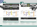
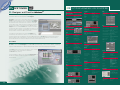
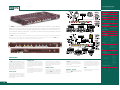
ALLEN&HEATH
ALL RANGES
ALLEN&HEATH
Kernick Industrial Estate
Penryn · Cornwall
TR10 9LU · UK
+44 (0)1326 372070
fax: +44 (0)1326 377097
tel:
email:
[email protected]
website:
www.allen-heath.com
www.idrseries.com
Allen & Heath reserve the right to alter any
information supplied in this document or any
other documentation supplied hereafter.
Training courses for iDR system building are
available worldwide.
Check www.idrseries.com for details or email
[email protected]
AP5909
ALLEN&HEATH
ALLEN&HEATH SOUND MANAGEMENT
ALLEN&HEATH is trusted by hundreds of thousands of audio professionals to
provide outstanding audio to venues around the world. For over 35 years,
we’ve produced great mixers for recording, broadcast, live sound, installed
systems and DJ’s, and our hands-on experience is
second to none in the industry.
ALLEN&HEATH SOUND MANAGEMENT SYSTEMS IN ACTION
Worldwide venues
using A&H Sound Management Products
Maritime Rescue Centre
Helsinki, Finland
Apeldorm Cultural Centre
Speyer, Germany
Natural History Museum
We’ve always been at the forefront of audio
engineering innovation: the first computer-controlled
mixer on the market in 1984 (CMC); the first dual function
live desk (GL3) in 1992; the first digital live sound console (Icon)
in 1998; the first affordable VCA console for live sound (ML5000) in 1999 and first
high-quality DJ mixers (Xone) for clubs and DJs in 2000. Our sound management
products benefit from not only years of software and digital audio development, but
also from years of crafting fine audio performance - to produce the best of both worlds!
London, UK
European Parliament
Strasbourg, France
OneWorld Sports Bar
Sydney, Australia
Montsouris Hospital
France
Bristol Dental School
UK
Hempfield United Methodist Church
PA, USA
Rennes Ice Rink
We developed our first truly ‘contractor’ product in 1994, when the GR1 zone mixer was
introduced. It was welcomed as a high-audio-quality zoner, which not only offered a
large number of inputs and outputs, but lots of user configuration
options so that the installer or engineer could create
exactly the system he wanted. This flexibility
proved to be the key characteristic which drove
the development of the DR series of DSP zone
mixing systems in 1997 - the software offered the user a
huge number of features and options for using the processing
power of the unit to create the ideal setup. Into the 2000’s, the iDR Series
followed this lead and offered a vast array of control and processing options whether over the internet, via networks or our proprietary PL-Anet system - and is
now growing into many contractors’ preferred system of choice for managing sound
systems in venues the world over.
Now, ALLEN&HEATH has a solution for any audio installation, of whatever size
or complexity:
✱ The GR05 offers 5 input, 4 output analogue zoning,
flexible architecture and numerous configuration
options for venue sound distribution.
✱ DR66 is a 6 in, 6 out DSP matrix mixing solution,
which allows the installer to program a huge number of
parameters of the system by software before installing hardware
✱ iDR is a range of hardware units and remote controllers which offer multiple
options for configuration and control of high quality live sound and fixed installations.
Since the early 1990’s, ALLEN&HEATH products have been at the heart of venues’
audio systems in auditoria, bars, conference centres, cruise ships, shopping
malls, clubs, theatres, lecture theatres, theme parks,
stadiums, houses of worship and a whole host of
unlikely places such as search and rescue centres,
funeral parlours and roller coaster rides!
Berjaya Times Square
London, UK
Lighthouse Evangelist Church
Singapore
Bogani Cafe
Oporto, Portugal
MI5 Building
London, UK
The Terrace Hotel
Macherafelt, N.Ireland
Tours,Cathedral
France
Sports Café chain
UK
Drugstore Publicis
Paris, France
Barry’s Douglas
Speicherstadt No.10
Ireland
Muenster, Germany
Fire & Ice Club
Ipswich, UK
Hornsby RSL
Sydney, Australia
Ministry of Sound
Taipei, Taiwan
Cock and Bull live music pub
Auckland, NZ
Intermarché Hypermarkets
France
Millennium Centre
Martin, Slovakia
Alton Towers
UK
BBC Outside Broadcast
UK
Lockheed Martin
USA
Aquadisiac Club
Singapore
Aruba Bar
UK
Tottenham Hotspur F.C. Ticket Office
UK
MLP Finance Group
Jockey Club
Aberdeen University
EDSA Shangri-La Hotel
2
Kuala Lumpur, Malaysia
Bloomberg Studios
Ferrari Store
What’s your
application?
France
Germany
Rome, Italy
Hong Kong, China
Scotland
Manila, Philippines
iDR SERIES WHAT IS IT?
iDR SERIES WHY IS IT SO USEFUL?
Network control
Automatic Level Management
Audio Quality
The main iDR units can be
easily controlled and
programmed with an
Ethernet connection to a PC
[or MAC running OSX & PC
simulator]. All iDR units on a network can
be ‘seen’‚ by more than one computer,
with optional password protection so that
operators can be observed by a technician
running iDR System Manager software - or
PL Client software - anywhere on the
network or World Wide Web. iDR can
even output a log of its activities to an
email address!
iDR is equipped with several
powerful modules to
manage a distributed sound
system, so an operator or
technician doesn’t always
need to be present. For instance:
Low latency [2.23ms from
input to output] and a fixed
DSP architecture ensures
that the iDR system will
distribute coherent audio
no matter how many modules of DSP are
used in the system.
Proprietary TCP/IP devices such as ‘WiFi’‚
can be used for cost effective and practical
uses; for example, a ‘wireless laptop’‚
can be used to commission or update
the sound system from exactly where the
technician needs to monitor it.
Preset System
The iDR is a 16 x 16 matrix mixer
with an extensive array of audio
management tools designed to
reduce the need for additional
devices to be specified for an
installation, or carried in the hire
inventory. Pedigree ALLEN&HEATH
preamps, 24bit converters and
fixed DSP architecture ensure
that concert-quality low-latency
sound is delivered efficiently to
where it is needed.
Anyone with a basic knowledge of traditional console and outboard equipment
will be able to design a distributed audio system on their PC using the ‘mixer’
based iDR System Manager software - download it free from www.idrseries.com.
iDR comes loaded with flexible DSP tools, essential in sound system configuration
and installation. Input & output delays, 4- and 8-band parametric EQ, automatic
microphone mixing, frequency conscious dynamics, look-ahead limiter, ambient
noise compensator, crossfader and much more are available at your fingertips
without having to worry about running out of DSP. Its system of presets allow for
full recall of the whole system or individual parameters at the touch of a button.
After programming, the iDR unit operates as a stand-alone system controller,
with a host of remote control devices available for day-to-day operation. The PL
Series complements the powerful features of iDR and comprises wall plates,
infra-red hand-held or desk mount controllers connecting to the main unit using
CAT5 cable over the RS485-based proprietary PL-Anet bus, while all the major
third party devices may also be used to control iDR.
For complex systems, the iDR system can be driven in real time by a PC via an
Ethernet port, allowing the iDR to be used in hire/live audio situations such as
matrix distribution in theatres, or clean feed system for an outside broadcast.
Why not connect a WiFi card to your laptop, connect to the internet, set up your
system and save your settings on the move? Stay in control from anywhere in
the world!
4
iDR provides a system of
up to 250 presets for total
recall of system settings. A
preset can contain the
settings for all system
devices, e.g. a default preset to set the
entire system on power-up, or individual
devices can be selected for exclusive
change in a preset, e.g. a single EQ or
fader gain level. A recall crossfader is
provided to fade between different preset
levels. Sheduled preset recalls are available,
timed from the iDR internal clock. Preset
recalls can be triggered from ALLEN&HEATH
equipment (PL controllers other iDR's or
iDR-Switch) or via the serial, MIDI and
Telnet ports using third party equipment.
PL-Anet
The PL Series
is the perfect
interface
between the
iDR and the operators on site, providing
simple, non-technical switch, indicator
display, fader, IR and encoder control
options. Furthermore, as the requirements
grow at an installation, the control system
can too.
PL remotes can simply daisy chain or
use the ‘PL-Anet’ hub for star wiring
applications, and all cabling is CAT5. You
as the designer can customize these
‘plug-n-play’ remotes to do exactly what
the customer needs. Each PL has its own
simulator in iDR System Manager software,
so you can design and demo the system
offline as it will appear when the hardware
is in place.
✱
Microphones in a conference situation
can be controlled by any one of the
four on-board AMM’s, so that as more
open microphones join in, the gain
of the sum is reduced to prevent
feedback occurring.
✱
A comprehensive Ducking system is
provided with adjustable priorities.
✱
Ambient Noise Compensator (ANC)
enables the output level in a zone to
be automatically managed in relation
to the signal level of the changing
background noise level
✱
Level Sensing provides a logic or
soft LED output when a pre-set signal
threshold is reached, which triggers
indicators and other hardware to
respond; this allows operations such
as camera following.
✱
2 independent paging systems are
provided, with paging to selectable
outputs. Paging switches and indicators
can be triggered via A&H controllers;
alternatively, custom paging panels
can be created and interfaced with
the system.
Expandability
As the system requirements
grow, additional iDR units
or expanders can be added
to suit the budget and
application. iDR-8 and iDR4 have 8-buss digital expansion ports
(RJ45) to allow units to be daisy-chained
together, or to add an iDR-In or iDR-Out
8-channel expander.
The CAT5 cables allow the units to be
placed at distances up to 250m apart,
allowing, for example, the iDR-In to provide
8 XLR mic/line inputs in a function room
on a different floor to the control room
containing the main iDR unit, or, similarly,
the iDR-Out could be configured as a
four-way-stereo XLR output to an amp rack
located at the side of a theatre stage.
Furthermore, the 8-buss link can be used
to distribute signals around a complex
network where iDR units communicate via
TCP/IP - here, interbox paging and routing
is possible.
Mic preamp gain is controlled in analogue
under software control so levels can be
optimised in real time if needed. iDR-8
has a hardware limiter before the A-D
converter so that the contractor can have
confidence in the signal integrity, even if
input levels exceed what was expected.
Signal Processing
The iDR-4 & iDR-8 signal
processing architectures
provide 16 channels of
input processing and 16
channels of output
processing, centred around the 16x16
mix matrix. Using the DSP patchbays, the
user can configure these channels to either
analogue inputs/outputs or to channels
on the digital audio expansion port.
DSP
Because of the fixed architecture, you do
not need to assign DSP into the signal
path, or worry about having enough DSP
available to do the job. In iDR, we have
given you the tools you need such as noise
gates, compressors, delays, parametric
EQ and look-ahead limiters, to start working
with live audio straight away.
Adjustments are made in real time as there
is no compiling to do, and our unique
monitor buss allows you to listen to any
point in the signal path. Copy and paste
any DSP settings to quickly build up a
design, save it as a configuration file, and
use it as a template for other systems.
MIDI
iDR-8 is equipped with MIDI
in/out/thru and custom MIDI
commands can be output
as presets and recalled on
the iDR. This allows other
audio devices such as samplers and
processors to be controlled from the
main unit.
For example, dynamic MIDI control from
faders, rotary controls and keys in the iDR
system could interface with a DMX controller,
so that basic lighting control can be
programmed into iDR and run from the
PL series remote controllers.
iDR -8
iDR -4
Features of iDR-8
Features of iDR-4
✱
iDR DSP system - 16 processing
channels (inputs and outputs)
✱
8 analogue mic/line inputs on XLR
✱
✱
2 line outputs on TRS jack
✱
Digital audio expansion port
with 48V phantom power
✱
8 analogue line outputs on XLR
2 line inputs on TRS jack
✱
Hot Plug‘n’Play PL Series
High Quality Audio Signal Path and
✱
DSP processing
✱
Headphone monitor with mouse and
✱
MIDI in/out/through connections
iDR DSP system - 16 processing
channels (inputs and outputs)
✱
ripple-through compatibility
(8 channels in, 8 channels out)
Remote controllers
6
✱
2 analogue mic/line inputs on XLR
with 20V phantom power
✱
4 analogue line inputs on TRS jack
✱
4 line outputs on XLR
✱
2 line outputs on TRS jack
✱
Digital audio expansion port
✱
Hot Plug‘n’Play PL Series
Remote controllers
✱
High quality audio signal path and
DSP processing
(8 channels in, 8 channels out)
✱
Monitor with mouse and ripplethrough compatibility
iDR -In & -Out EXPANDERS
iDR CONTROL
iDR-In
A glance at the iDR back panel reveals the scope of iDR’s control capabilities. iDR can communicate with
many forms of equipment utilising industry standard communication protocols. For example, iDR-switch
units, iDR-in and iDR-out expanders, third party controllers, PL Series ‘intelligent’ wall plates, MIDI show
controllers, PCs, networks and modems. Up to 4 communications ports can be used at once - network
and DR-link ports are always available, with two more selected from RS232, Sys-Net, MIDI and PL-Anet.
Rear panel LEDs clearly indicate active ports for rapid communication status checking.
COMMUNICATIONS PORTS - iDR System
permanent protocols
connections
Network
protocol type
uses
Network control and communication between computers,
connection of iDR System Manager, PL-Designer and
PL-Client. Connection to the internet for remote
iDR-Out
management and control purposes
DR-Link
iDR-Switch to the iDR units for logic control.
iDR-8 and iDR-4 can happily manage many complete systems with their existing input/output architecture
standing alone. However, for larger systems, iDR-In and iDR-Out audio expander units are available, providing
an additional 8 mic/line inputs on XLR and 8 line outputs (also on XLR) respectively. One or both
expanders may be connected to a single iDR main unit.
These audio expanders convert the analogue audio to an 8 channel wide digital bus which feeds the main iDR unit,
which can be up to 250 metres away, via CAT5 STP cable. iDR-In features high grade mic/line preamps with PC
configured gain, pad and phantom power switching via DR-Link, and a built-in soft clip, while iDR-Out provides
electronically balanced differential outputs. Both units have 8 front panel LEDs in addition to the 3 status indicators;
these are 3-colour soft LEDs which can be assigned as audio meters, mute indicators or presets related indicators
and are programmed in the usual way using the iDR System Manager software.
Example Combinations:
2 of 4 protocols selectable from software
Sys-Net
For third party controllers such as: AMX, Crestron, Cue,
Audace and many more. Touch screens, Infr-red devices
etc can be utilised with iDR.
RS232
For connecting iDR to a phoneline for remote connection,
management and operation
(PPP = Point to Point Protocol).
RS232 Front
Used to update the system code in the unit
6x6
8 Inputs
Links the iDR-In and iDR-Out audio expanders and
10x10
Local
Inputs
Many iDR Units can be inserted on the digital audio bus
Local
Outputs
6x14
(iDR-8 only)
10
Outputs
10 Inputs
16x10
Local
Inputs
Many iDR Units can be inserted on the digital audio bus
Local
Outputs
8
Outputs
8
MIDI
6
Outputs
6 Inputs
(iDR-8 only)
16x16
PL-Anet
For Remote Control using standard MIDI interfacing
equipment. Custom remote controllers, show control,
MIDI conversion equipment (e.g. MIDI to DMX) to
control external equipment (e.g. lighting)
PL-Anet is an RS485-based protocol incorporating 20V
phantom powering for the ALLEN&HEATH self detecting
and self powered PL Range of remote controllers.
iDR System Technical Specifications
Audio Specifications
Performance
Frequency Response
Inter-channel Crosstalk
THD + noise
Residual output noise
Input to Output noise
20Hz to 20kHz +0/- 0.5dB
<-80dB @ 1kHz, 0dB gain
<0.01% @ 1kHz, 0dBu
<93dBu (22Hz to 22kHz)
<87dBu @ 0dB (22Hz to 22kHz)
iDR-8 - number
iDR-4 - number
Connections
Type
Impedance (pad out)
Impedance (pad in)
Gain
Sensitivity (pad out)
Sensitivity (pad in)
Max Input
Limiter
8 (expandable to 16)
2 (expandable to 10)
Female XLR 3 Pin
Electronically Balanced, pin2+
2k ohm
>10k ohm
Control in 3dB steps, 20dB pad
-50 to -5dBu
-30 to +15dBu
+33dBu
Pre-ADC opto - 6dBFS, switchable
Phantom Power
+48V switched (iDR-8)
+20V switched (iDR-4)
Headphone Output (iDR-8 only)
Front Panel (face plate fitted)
Connections
Type
Impedance
Control
Display Type
Display content
2 x 16 Character Backlit LCD
Day/Time, unit name, user defined text,
Menu/operating control data
Keys
iDR-8: 16 user programmable, 2 scroll
iDR-4: 8 user programmable, 2 scroll
iDR-8: 32 user programmable, tri-colour
iDR-4: 16 user programmable, tri-colour
iDR-8 only: Recessed Socket and
Level Trim
TRS Jack, Tip L Ring R
1/4" Stereo Jack
For Headphones >30ohms
Front Panel Trim Control
DSP
Processing
Sampling Rate
Audio matrix (48kHz)
Latency XLR in to
XLR out with Processing
LEDs
2x Motorola
56bit mix accumulator
48kHz
16 x 16 channel processing
<2.3ms
Headphones
Front Panel (face plate removed)
Menu Keys
Menu Items
Menu item select using: scroll, esc, enter
Preset Recall, Monitor Select, date/time,
unit name, network, diagnostics
24bit
109dB A-weighted, 106dB unweighted
Status LEDs
RS232 Connector
iDR-8 only: Slave, Ext. Sync Lock, 96kHz
iDR-8 only: 9 pin D Connector Mirrors Port A protocol setting, front/rear
selection switch
24bit
115dB A-weighted, 112dB unweighted
Code Update
Label Strip
Updates iDR operating system code
Behind widow user label/markup strip
A/D Converters
Resolution
Dynamic Range
D/A Converters
Resolution
Dynamic range
TRS Jack Line Inputs
Expander Input Port
Power Supply
iDR-8 - number
iDR-4 - number
Connections
Type
Impedance
Sensitivity
Max Input
Application
Type
Connector
Power Lead Supplied
Power Switch
AC mains input
2
4
TRS Jack (balanced/stereo Jack)
Electronically balanced, tip+
>30k ohm
0dBu
+18dBu
Connection
Protocol
Cable
XLR Line Outputs
8 (expandable to 16)
4 (expandable to 12)
Male XLR 3 Pin
Electronically balanced, pin2+
<75 ohm
+18dBu
adding remote inputs (iDR-in) and linking
iDR units on 8 channel digital bus
RJ45
Propietary 8 Channel Digital Audio
CAT5 STP upto 250m (825 feet)
Expander Output Port
Application
iDR-8 - number
iDR-4 - number
Connections
Type
Impedance
Max Output
iDR -Switch
Technical Specifications
DSP
XLR Mic/Line Inputs
for iDR-8 & iDR-4
Connection
Protocol
Cable
adding remote Outputs (iDR-out) and
linking iDR units on 8 channel digital bus
RJ45
Propietary 8 Channel Digital Audio
CAT5 STP upto 250m (825 feet)
Universal Input Switched Mode
IEC 3pin
Country Dependent
Rear panel mains on/off
100-240V AC 50/60Hz
Power Consumption (Max) iDR-8: 80VA
iDR-4: 75VA
Internal Fuse
iDR-8: T1.6A 20mm
iDR-4: T1A 20mm
iDR-switch extends the capability of the iDR-8 and iDR-4 by enabling
custom wall plate and remote equipment control. It provides 24 switch
closure inputs and 16 logic control outputs which can be custom wired
by the installer to suit the application. Up to 3 units can be networked,
so providing an iDR unit with 72 switch and 48 logic outputs. The
controls are easily programmed using the System Manager software.
Control Functions
Software
When a switch contact closure status is
ACTION ON (Pressed) or ACTION OFF
(released) various parameters can be
controlled within the iDR system:
iDR System Manager has a simulation of
iDR-Switch units connected to the iDR
unit (maximum of 3 per unit). The Switch
can be setup online or offline and has
the ability to show Logic outputs as green
LEDs. Setting up the contact closures
and logic outputs is done in the Soft Keys
and Soft LEDs setup windows. Many
external devices can be integrated into a
system using the iDR-Switch units and
custom paging panels and remote
triggering can be realised.
✱
Levels [Up/Down]
(Input, Output, Crosspoint, Monitor)
✱
Group Levels [Up/Down]
(Input, Output, Crosspoint)
Dimensions
iDR-8
iDR-4
✱
Desktop
Width
Height
Depth
440mm (17")
92mm (3.5")
350mm (14")
440mm (17")
48mm (2")
350mm (14")
Mutes [Toggle/On/Off]
(Input, Output, Crosspoint, Monitor)
✱
Preset Recall
[offers all associated functions]
Rackmount
Width
Height
Depth
(2U)
486mm (19")
88mm (3.5") = 2U
350mm (14")
(1U)
486mm (19")
44mm (2") = 1U
350mm (14")
TRS Jack Line Outputs
Quantity
Connections
Type
Impedance
Max Output
2
TRS Jack (balanced/stereo Jack)
Electronically balanced, tip+
<75ohm
+18dBu
Max depth with connectors
Depth
430mm (17")
✱
Monitor Select [Inputs/Outputs]
✱
MIDI Strings - iDR-8 only
(a custom MIDI string is sent from
the iDR Unit)
A range of different modes of operation
for each switch closure and logic output
can be achieved. Many systems can be
integrated with the iDR-Switch, e.g. -
430mm (17")
Operating Modes
Control & Communications
Control Ports
Network (TCP/IP)
offering the following combinations
Application
PORT A
RS232
PORT B
Sys-Net
Connection
RS232
RS232
RS232
Sys-Net
MIDI (iDR-8 only)
PL-Anet
Custom Serial
PL-Anet
Settings
PPP Setup
Cable
Sys-Net
MIDI (iDR-8 only)
Custom Serial
Custom Serial
MIDI (iDR-8 only)
PL-Anet
MIDI (iDR-8 only)
PL-Anet
Front Panel Connector
Rear Panel Connector
Baud
Cable Length
Front panel switch to select either front
or rear RS232 connector
9pin D Female
(Modem) 9 Pin D male
115200, 8N1
<3 Metres (10feet)
MIDI (iDR-8 only)
Application
Connection
Protocol
Applications
Connection
Protocol
Cable
Network for ALLEN&HEATH PL Series
intelligent remote controllers
RJ45
Application
Remote Parameter Control via MIDI
sequencer/Interfaces, Show Automation
Opto isolated MIDI IN, OUT,
THRU 5 pin DIN
Note on/off, program change,
NRPN, Custom Strings
Connection
Protocol
Cable
Proprietary ALLEN&HEATH
CAT5 STP up to 250 metres (825 feet)
Theme Park Triggering
✱
Room Dividing
✱
Latched Action
✱
Custom Paging Panels
✱
Press Action
✱
Custom Switches for Level control
✱
Release Action
✱
External Equipment interfacing (e.g.
Start/Stop for a motor unit utilising a
suitable relay interface)
Proprietary ALLEN&HEATH - RS485
with +20VDC Phantom Power
CAT5 STP (Refer to REN table lengths)
iDR-Switch and iDR audio expander
logic control
RJ45
Fire Alarm Interface
✱
Front Panel
Status LEDs
Link, power
Switch Inputs x 24
Connector
3x 10pin Phoenix, 8 switches
per connector
Plug
Mating screw terminal plugs supplied
Type
Opto-isolated via 2k2 ohm from +10V
Operation
Switch closure to connect pin to
ground (5mA)
Cable
1k ohm max resistance
Logic Outputs x 16
Connector
4x 10pin Phoenix, 4 outputs
per connector
Plug
Mating screw terminal plugs supplied
Logic Outputs x 16 (continued)
Type
Opto-isolated open collector
Terminals
Floating collector (+) and emitter (-) pins
Internal DC source
+10V, 500mA total max. External DC
source. Up to +24V 200mA sink per
output max
DR-Link
Application
Connection
Protocol
Cable
Logic control from iDR-4/8
RJ45 x2 (in, out to next unit)
Proprietary Allen & Heath
CAT5 STP up to 250 metres (700 feet)
Power Supply
Type
Connector
Power lead supplied
AC mains input
Power consumption
Fuse
Power switch
Universal input switched mode
IEC 3pin
Country dependent
100-240V AC 50/60Hz
15VA max
T500mA 20mm
Rear panel mains on/off
Mechanical specifications (in mm)
Removeable ears for desk or rack mount
Width
iDR-switch
Desktop
Rack
Unpacked weight
Packed weight
440mm
(17.3")
486mm
(19")
Height
Depth
48mm
(1.9")
44mm
(1.75")(1U)
148mm
(5.8")
148mm
(5.8")
3.5kg, 7.7lb
4kg, 9lb
PL-2
OUTPUTS
INPUTS
The PL-2 is a purposebuilt custom interface
for iDR-Switch available
from A&H for those who
do not wish to make
their own custom
panels.
Sys-Net
Application
Connection
Protocol
Baud Rate
Cable
10
iDR System Manager, PL Designer/
Client, Telnet
RJ45 Ethernet MDI/X Switch
For Hub or Direct connection
DHCP, IP address, Net mask, Gateway
Host IP, client IP, user name, password
CAT5 UTP up to 100metres (330 feet)
DR-Link
RS232
Port Select
PL-Anet
✱
Technical Specifications
Remote Parameter Control,
Third Party Controllers (e.g. AMX)
RS232 9pin D Female
ALLEN&HEATH Sys-Net,
Custom Serial Strings
Custom settings available
<3 Metres (10 feet)
The wallplate has 4 user-programmable
switches and 4 tricolour programmable
LEDs providing many local control options
such as multiple source selection for
output zones.
PL -Series
The PL series is the perfect interface between the iDR and the operators on site who don’t need to
understand the sound system - just control it. As the requirements grow at an installation, the control system
PL-7
can too! Start off with just the controls and display on the iDR unit then add wall mounted plates and handheld remotes wherever they are needed using our CAT5 PL-Anet cabling system. PL remotes can simply
daisy chain or use the PL-Anet hub for star wiring applications. LEDs in the system can be tri-colour status
indicators [to indicate selected sources, or mutes] or they can become meters for any point in the signal
flow. The LCD windows can easily be programmed to relay text information about the state of the system.
You, as the designer, can customise these plug and play remotes to do exactly what the customer has been
PL-7 is a stand-alone or surface mounted LCD
panel, which enables remote display of status
information and text messages which can be
stored in the recallable memory settings. The
PL-7 can be embedded with PL-3 or PL-4 wall
plates, allowing programmable control from a
single unit. It can also be used for remote
alarm/supervisor display.
looking for. Each PL has its own simulator in iDR system manager software so you can design and demo the
system offline as it will appear when the hardware is in place.
PL-8
PL-3 & PL-4
PL-8 is a 4 input, 4 output logic control panel mounted on a wall plate which can be
connected to PL-Anet. It is designed to interface external systems such as alarm systems,
juke boxes, room dividers, fader starts and lights at a convenient location.
PL-3 and PL-4 wall plates have 4 or 2
programmable switches and 4 programmable
tri-colour LEDs and are ideal for local
operator control of the iDR-based audio
system. They may be used, for example,
for source selection for an output zone,
or local volume control. The PL-4 has, in
addition, a rotary control with LED ladder
and a built-in infra-red receiver - it can be
operated at a distance using the PL-5
handheld remote controller, allowing the
operator to quickly and conveniently adjust
the system from anywhere in the room.
The control options can be different to
those set on the PL-4.
PL-6
The PL-6 is ideal as a remote mix controller - e.g. as a simple
operator-controlled fader panel in an installed sound system, or
as a personal musician’s on-stage mix controller with in-ear
monitors. It has 8 faders, 24 tri-colour LEDs and 16 soft switches
which are all programmable via iDR System Manager. Other
examples for use include as a basic lighting controller via
MIDI/DMX, and the unit can be wall-mounted or flange-mounted
into a table or wall.
PL-5
Examples of use: multiple source selection
for an output zone. Local volume level,
home cinema & AV system control
(projector / lighting / amplifier control),
and tamper-proof control.
PL-9
PL-9 is a 1U rack or desk mount hub which provides up to 7 individual connections to chains of PL devices, offering ‘star wiring’, simplifying
wiring and eliminating the need for complex daisy-chaining. This also provides the benefit of longer cable runs and allows easier ‘plug and
play’ of devices such as the PL-6 and PL-10, and allows a larger number of PL controllers to be connected to a single iDR unit.
As the PL-9 is the ‘end of chain’ on a PL-Anet branch, it offers greater flexibility by allowing PL wallplates to be plugged in and out easily –
for example, a PL-6 could just be plugged into a PL-9 onstage, allowing local performer control, then removed after the event.
PL-10
The PL-10 is similar to the PL-6 - i.e. is a compact mixer interface,
but has 8 rotary encoders, with LED ladder displays instead of faders,
making it possible to mix live events within the iDR system. It’s
ideal for creating and controlling an output mix of cross-point
groups. The PL-10 can be assigned to read and adjust different
mixes, as the LED bars indicate the levels managed by the iDR
unit. The unit can be hand-held, or flange-mounted into a table or
wall. As the PL-10 has encoders rather than faders, it can respond
to changes in levels made from other controllers.
PL-Calculator
PL-Calculator is an Excel-based program which enables the installer
to verify that a planned system with specified PL devices and interconnect distances over
PL-Anet conforms to the
system specification. The
program is bundled together
with the iDR System
Manager software.
PL-Anet Specification
Application
Connection
Protocol
Cable
12
Network for ALLEN&HEATH
intelligent remote controllers
RJ45, RS485 with +20V DC
phantom power - terminator supplied
Proprietary ALLEN&HEATH
CAT5 STP (Length table available
from ALLEN&HEATH)
PL SOFTWARE
PL Designer and Client for WindowsTM
iDR SYSTEM MANAGER SPECIFICATIONS
Operating System
iDR Unit Software, Internal
Compressor (x16)
Update using TCP/IP via system
manager, RS232 via Hyperterminal
System Configuration
As well as being controlled by iDR System Manager, iDR systems can be controlled via a PC using ‘PL Client’,
an interface which can be designed in ‘PL Designer’.
iDR System Manager software PC compatible running online or
offline session. Includes all iDR
and PL unit simulators for
complete setup and test
PL Designer is used to create a custom interface which is opened using
Threshold
Ratio
Knee
Makeup Gain
Attack
Release
Auto Modes
Display
Controls
PL Client. The system architect can create a custom wall plate in PL Designer,
AMM (x4)
-48 to +18dBu
Variable 1:1 to 1:infinite
Hard, Soft
0 to +18dB
300_s to 300ms, auto mode
100ms to 2s, auto mode
Live, Music AGC, Vocal, Speech
Response curve, gain reduction,
in/out/sidechain meters
Compressor in/out,
Sidechain in/out, auto on/off
Automatic Mic Mixing
Ambient Level Sensing
Mic open threshold
Hold time
NOM Attenuation
NOM and ambient level
average of all selected mics
4 to 20dB above ambient level
0 to 5 seconds
1 to 6dB
providing system control taliored to the user’s requirements. PL Designer
lets the architect create a control layout from a selection of control types,
such as switches, faders, mutes and meters, and positioned over a bitmap
background. The architect can map functions from the iDR units into the
Designer interface. The resulting PL Client panel, designed and customised
according to the client’s preference, can be installed on the client’s PC. The
result is the creation of customised, virtual wall plates. The PC can then be
directly or network connected to the iDR for system control.
Virtual Controllers
PL-Designer
PL-Client
for installer configured GUI
for restricted operator control
Source Patchbay System
Selectable physical source for
each input and output channel
Eliminates the need for a physical
patchbay and signal splitters
For example, the system architect could specify in PL Designer that: a
and levels of different zones on multiple floors using many iDR systems through one PL Client interface from the client’s passwordprotected computer system. Further levels of access may also be added: for example, assistant managers of the venue may be
Input (x16) (iDR-8 only)
Time
Units
Temperature
provided with restricted access offering the ability for level control of their designated area only.
Output (x16)
Time
Units
Temperature
PL Client
PEQ
PL Client, created with PL Designer, a tool within iDR System Manager, is the end user software, containing
only the control elements in a .drd file with the design devices removed for tamperproof operation.
Input (x16)
PEQ Type
Band Type
Range
Width, Q variable
The PL Client software is demo-ware and time limited to 10 days. After that
Display
Controls
Linear fader range
Controls
0 to 340ms per channel
ms, metres, feet
Global Adjust Coefficient for
-20 to +40 degrees C
Fader Range
Number of Input Fader Groups
Number of Output Fader Groups
Number of Crosspoint Fader Groups
Group naming
the online documentation and help file contained in the iDR system
manager software.
Range
Crossover filter
Width, Q variable
Display
Controls
Metering
Input
Metering Points Input
8 band fully parametric including
crossover filter type
HF shelf, LF shelf, Bell, HPF,
LPF, notch, crossover filters
+/-15dB cut/boost,
+/-12dB makeup gain
upto 24dB/oct, Butterworth,
Linkwitz-Riley, first order
0.5 to 6, constant Q on/off
(notch width 10Hz to 100Hz)
frequency response curve, meter
in/out, reset
Gate (x16)
Threshold
Depth
Attack
Hold
Release
Display
Controls
automatic controlled gain element
in step with changes in background
noise levels
Ambient Level Metering Point I/P Source/Post-EQ/Post-Fade, O/P
Post-Matrix/Pre-Fade/Post-Limiter,
Channels 1-16
Ambient Level Gain Differential -18dB to +40dB
Controlled Gain Element
selects fader for control, I/P, O/P, I/P
Group, O/P Group, Routing Gain,
stereo operation
Controlled Gain Operating Range min -59 to 5dB, max
Controlled Gain Response Time rate dB per Second from 0.1
to 30dB
Program Gap Metering Point
I/P Source/Post-EQ/Post-Fade, O/P
Post-Matrix/Pre-Fade/Post-Limiter,
Channels 1-16
Program Gap Threshold
-62dB to -20dB
Program Gap Time
0s to 5s
Display
Level meters, Ambient Level
Sampling Active LED
Controls
Enable On/Off
Adjacent channels can be linked for stereo operation
Presents single channel strip
Processing Linked
Matrix routing Linked
Stereo Metering
Output
Band Type
Ambient Noise Compensator
Stereo Linking
4 band fully parametric
HF shelf, LF shelf, Bell, HPF,
LPF, notch
+/-15dB cut/boost,
+/-12dB makeup gain
0.5 to 6, constant Q on/off
(notch width 10Hz to 100Hz)
frequency response curve, meter
in/out, reset
www.idrseries.com/pl_client.asp
Output (x16)
PEQ Type
Off to 0dB in 51 Steps
8
8
16
up to 8 characters
0 to 340ms per channel
ms, metres, feet
Global Adjust Coefficient for
-20 to +40 degrees C
a key is required to run the software which is available from
For more information on setting up and configuring PL Designer/Client view
Off to +5dB in 51 steps
Level, Mute, polarity reverse
Fader Grouping
Channel Faders can be assigned to be master faders (DCA)
Delay
venue manager could control source selects (e.g. CD, SAT-TV, DVD, etc),
ANC (x4)
Level Control
Input channels, output channels, monitor bus, signal generator
-72 to +18dBu
0 to -80dB
20_s to 300ms
50ms to 5s
50ms to 1s
Level response curve, gate active,
in, out, sidechain meters
Gate in/out, sidechain in/out
Metering Points Outputs
Assignable LEDs
Metering
Meter styling
Input Meters selectable source,
post-EQ, post-dynamics,
post-fade
Output Meters selectable post
matrix, pre-fade, post-fade,
post-limiter
Source, Delay, EQ, Sidechain,
Gate, Compressor, Fader
Delay, EQ, Fader, Limiter
(can act as meters) green from
24dBu, yellow from 0dBu,
red from +14dBu
(4dB below clipping)
Extensive on-screen display for all
signal points in the signal path
Select 1 of 4 meter bar display types
Mix Matrix
Input / Output channel crosspoint (X/P) matrix
Switch/gain matrix
Matrix size
Fader range
Controls
Matrix Groups
Controls
Type
Priorities
Threshold
Depth
Release
Controls
16 channel multi priority selectable
1 (max) to 16 (min)
-48 to +18dBu
0 to -60dB
1 to 100dB/s
Ducker Enable On/Off
Pager (x2)
Type
Paging
Zone Select
Indicators
16 x 16
-38 to 0dB (-inf shutoff)
set, clear, mute, individual,
row, column, all
16 freely assignable groups
Output Limiter (x16)
Threshold
Attack
Release
Display
Ducking
Ducker Depth
Controls
2 independent configurable pagers
Activated from Front Panel,
PL-Anet, MIDI, Sys-Net,
iDR-Switch, networked iDR
Activated from Front Panel,
PL-Anet, MIDI, Sys-Net,
iDR-Switch, networked iDR
Front Panel, PL-Anet, MIDI,
Sys-Net, iDR-Switch,
networked iDR
0 to -40dB
page mic select, zone select,
latching, press to talk, auto cancel
Audio Monitor
-20 to +18dBu
40us to 400ms
50ms to 1s
level response curve, gain reduction,
in, out, meters, time versus
reduction histogram
in/out, fader
Ripple through stereo audio monitor
Source Select
I/P 1-16 source, Delay, EQ,
Sidechain, Gate, Compressor, Fader
O/P 1-16 Delay, EQ,
Fader, Limiter. Channel Outputs
1-16 (routed via output patchbay)
Follows Mouse / Active Window
Sidechain Filter (x16)
Source
EQ
Switch into either compressor
and/or gate
1 Band, type and parameter
control as PEQ
Signal Generator
Source variable frequency
Range (sine/band)
Controls
14
sine wave, white noise, pink noise,
band pass pink noise
20Hz to 20 kHz
Fader, Mute
DR 66
Technical Specifications
0 dBu = 0.775 Volts rms
The DR66 is a Digital Signal Processing Matrix Mixer which can be used for a huge number of sound installation
applications. Built around two Processing Engines supplied as standard, this compact 1U rack unit offers digital
mixing with EQs, dynamics and automatic mic mixing, and provides routing for signals from the 6 analogue
mic or line inputs to be fed to 6 matrix outputs on XLR connectors - a system which can be expanded with
additional processing engines and delay options.
Internal Headroom
DR66
+12dB
Maximum Output Level
+16dBu
into 600 ohms
Frequency Response
20Hz to 20kHz
+/-1dB
Distortion
THD better than
0.004% @ 1kHz
Crosstalk
Interchannel
> -80dB at 1kHz
Noise 22Hz - 22kHz
Mic Ein
Line preamp at
Mix noise (all routed)
-128dB (150 ohms source)
0dB gain -90dBu
-80dBu
Panel Meters 2 colour
Red:
Green:
Peak -6dB dBFS
Signal -42dB dBFS
Phantom Power
+18V, internal jumper links
Power Requirements
Mains voltage set for local requirements 50/60Hz 25W max
Power Supply
Internal regulated hybrid Switch Mode/Linear
The DR66 is simple to set up using ALLEN&HEATH WinDR System Manager software and can be controlled either by front panel keys
on the unit standing alone, or by many other methods, such as wall plates, touchscreens and the front panel keys. Programmed presets
can store parameters of several processing elements and the settings of input, crosspoint and output faders, which can then be recalled
manually, or by the timed events processor. The DR66 boasts rear connectors which allow input from a single 24V backup power supply.
Power Consumption
25VA Max
AC power requirements
Factory wired for 100, 120, 220, 230V AC,
50/60Hz mains input
Fuse
T315mA
(220V - 240V AC)
T630mA
(100 - 120V AC)
The DR66 is designed to provide low latency architecture in Digital Signal Processing mixing, and it’s built to the same exacting standards
as ALLEN&HEATH live sound desks. Bringing well-featured, high quality audio to every sort of sound installation, this audio zoner offers a
low-cost DSP solution for installations such as hotels, conference centres, stadia, retail outlets, restaurants, houses of worship and pubs.
DC Power Backup External DC Power Supply Input
Nominal +24V DC (+/- 15%)
DR66
Fuse 2A
(internal)
1 Amp max
Mechanical specifications - Dimensions in mm
Desktop
Width
Height
Depth
486 (19")
44 (1.7")
350 (14")
Sizes do not include feet
Weight
7kg (15.4lb)
20-bit Fs x 64
DAC
:
:
20-bit Fs x 128
Digital Signal Processing
LCD Display
SysNet
Delay Option
WinDR Software
DR66 is supplied with two Digital Signal
Processing Engines (PE’s) as standard, and each
has a different contribution to make towards the
functionality of the unit. The first PE has a fixed
configuration and powers the matrix processor,
input and outputs, signal meters, crosspoint
matrix, output protection limiters multiple priority
ducker, AMM and ‘soft’ insert points for signal
processing.
The LCD displays active patch number, name, day,
time and other information. A real time clock is
included for scheduled patch events.
SysNet is the ALLEN&HEATH communication
protocol used to control the DR unit from external
third party remote controllers, such as AMX, Crestron
or Audace. Patch recall, input and output levels,
mutes and crosspoint levels can all be controlled
from such devices via the RS232 port.
The DSPd Delay Option provides up to 680mS of
signal delay on each output channel.
WinDR is a WindowsTM application which runs
on PC or networked system. It is supplied with
the DR66 for the installer to configure the
internal routing and signal processing for the
installation. Three main windows are available:
✱ Offline DR Unit simulation window, with
front panel controls for remote functions and
display options
✱ Input and output channel windows, with
show controls for each channel including
faders, mute, polarity, naming and
crosspoint levels
✱ The resource toolbar which shows the
available DSP in resource racks, which can
be assigned by dragging onto channels.
✱ WinDR can be investigated before real
system setup by downloading it free from
the ALLEN&HEATH website.
Patches
Each DR unit can store up to 99 patches depending
on the resources involved. Full patches [affecting
all parameters] or partial patches [affecting selected
parameters] can be edited using the PC then named
and saved to the DR. Sets of programmed patches
with channel names, scheduled events details and
processor rack details can be saved in configuration
files on PC.for system recall.
Setup Keys
The DR66 has five soft keys on the front panel
which can be used to navigate and select available
menu parameters.
16
Packed
6.5kg (14.3lb)
ADC
FEATURES
The second PE allows indivitual assignment of
signal processing and allows the installer to load
‘resource racks’ of DSP with, for example,
parametric EQ’s, graphic EQ’s, noise gates and
compressors which may be applied to inputs and
outputs. Further DSP may be added with extra
‘DSPx’ expander cards.
Unpacked
DR Gateway
This is an ALLEN&HEATH WindowsTM software
utility which allows the DR66 to be controlled
via an IP network. This lets the installer access
the unit remotely using the WinDR System
Manager software via a computer network, through
an Ethernet port or dial-up connection. It runs on
a host computer via RS232 and its Ethernet port
to access the network.
iDR Switch
The DR66 can be connected via DR Link on
CAT5 cable to the iDR-Switch, a 24-in, 16-out
switch controller (see page 11). The addition of
the switch unit allows extensive use of wall plate
and remote equipment control, and provides an
additional 24 switch closure inputs and 16 logic
control outputs which can be custom wired by the
installer to suit the application. Up to 3 units can
be networked, providing an extra 72 switch and
48 logic outputs and are programmed using the
WinDR System Manager software.
External PSU Backup
Rear connectors provide input from a single 24V
external battery
Processing
2 x Motorola 56002
24-bit fixed point
Sampling Frequency
48kHz
Compatible with BS5839 installation requirements for Alarm systems,
plus IEC65, EN60065, UL6500 and CSAE65/94 safety standards
PL-1
The PL-1 wallplate has
4 user-programmable
switches and 4 tricolour
user-programmable
LEDs providing many
local control options
such as multiple
source selection for
output zones.
Technical Specifications
GR 05
0dBu = 0.775 Volts rms, +4dBu = 1.23V rms,
0dBV = 1 Volt rms, -10dBV = 316mV rms
Maximum output level
Impedance balanced
+20dBu into 2k ohm
Frequency response
20Hz to 30kHz
0/-1dB
Distortion - measured at +12dBu 1kHz Line in to Output
< 0.005%
Crosstalk measured at 1kHz
Channel shutoff
Interchannel
Channel pan
< -90dB
< -80dB
< -75dB
Noise 22Hz - 22kHz referred to 150 ohm source
Mic EIN
Line preamp at 0dB gain
Mix noise (all routed)
-128dB
-91dBu
< -86dB
Inputs + Output Meters
3 colour LED
Red:
Yellow:
Signal:
The GR05 is an affordable yet high quality ‘plug and play’ analogue 1U rack solution for sound installations,
mixing up to 2 mic and 3 stereo sources for up to 4 output zones. It presents a very simple interface for the
operator, but has amazing installer configurable flexibility protected ‘under the hood’. It provides tools such
as level matching, metering, routing matrix , EQ, ducking, VCA remote control and expandability to satisfy the
many demands of each installation.
Peak: on 5dB before clipping
0dB
dynamic indication from -12dB
Internal headroom
+20dB
Routing
Assignable 9 in,
4 (x2) Out
Crosspoint Matrix
Output Levels Control
Routed Direct
The GR05 is at home in small but high quality professional sound installations providing zoned background music and announcements,
with sources such as microphones, CD, 2-track players, retail radio feeds, video sound, jukeboxes, etc. Venues where GR05 can be
Routed via VCA
found include bars, shops, sports centres, restaurants, public galleries and venue foyers.
Ducking options
High performance VCA system
Internal trimmer
-10dBV to +4dBu
Front panel level control or
External remote level control
Switch operated zone mute
option link
Internal Trimmer
-10dBu to +4dBu
Ducking - Release fast or slow links
Depth
-10dB, -20dB or Mute links
Internal & External Ducking circuits.
Internal Trigger from mic 1
and mic 2 by option links.
External Trigger from opto
isolated input
EQ
Mic Inputs
HF/MF Swept
Peak/Dip, LF Shelf
HF Shelf, LF Shelf
Outputs
Power Supply Internally regulated +/- 15V
Mains Power Internal unit
AC mains input
FEATURES
:
2 Microphone Inputs
Outputs XLR
Routing Matrix
Ducking
Lock Out System
The GR05 is furnished with 2 balanced mic inputs
on XLR, both of which have rear panel gain controls.
Removal of the top panel allows access to internal
jumper links, providing a 30dB attenuator pad, +15V
phantom power and a high pass filter at 200Hz.
Internal trimmers also provide 2-band EQ, hi-mid
frequency with sweep and LF shelving. The front
panel has 3-colour LED meters, and level controls
for all routed outputs.
4 XLR connectors are provided for the outputs,
which are internally configured by the jumper links
for -10dBV to +4dBu. The outputs can be grouped
and front panel level controls can be disabled using
the internal. Internal trimmers also provide shelving
EQ for HF and LF.
All inputs can be routed to any combination of
outputs direct, or via VCA control, so that the direct
path is not affected by output level controls and
ducking. Matrix assigment is achieved using
internal jumper links.
The GR05 allows ducking and muting of
channels, and is configured either internally on
jumpers or externally via an opto-isolated input
for external trigger.
Input controls are always active; output levels
controls may be disabled. All level controls may
be set in 3 ways: 1) Knob fitted for operator control
2) knob removed for screwdriver preset 3) hole
plugs (provided) fitted to lock out control.
Stereo Inputs
3 RCA sockets are provided for stereo inputs, and
internal jumper links allow access to -10dBV to
+4dBu level matching. 3-colour LED meters and
level controls are also provided for the stereo inputs
on the front panel.
18
Power consumption
Mains fuse rating
:
Other configurable functions include VCA control
and outputs which can be assigned to front panel
controls or alternatively, remote control operation.
Zone muting is possible via a front panel switch
and LED indicator.
A status LED on the front panel is provided.
Remote Control
VCA path remote control can be configured by the
installer on internal jumpers. The expander option
(using another GR05 acting as slave to the main
unit and connected by a 25-pin D connector)
includes a remote DC input for each of the 4 outputs.
Expander / Remote
Additional mic & line inputs can be provided via
another ‘slave’ GR05 using the 25-pin D-type
female connector.
DC Power Backup
100 to 230V a.c.
@ 47-63Hz
Internally wired to
country voltage
18VA max
100-120V a.c. use
T630mA 20mm
220-240V a.c. use
T315mA 20mm
External d.c. power
supply or batteries
+/-12V to 16V d.c.
@ 300mA
Mechanical specifications - Dimensions in mm
Width
Height
Depth
PSU
Desktop
483
(19")
44
(1.7")
260
(10.2")
Internal mains voltage PSU. DC backup input is
provided. Status indicator.
Weight
4kg
(9lb)