1
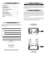
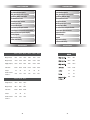
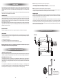
BMF200.2 | BMF300.2 | BMF400.2 | BMF600.2 | BMF400.4 | BMF600.4
BMF800.5 | BMF250M | BMF500M | BMF1000D | BMF1700D
TABLE OF CONTENTS
IMPORTANT MESSAGE . . . . . . . . . . . . . . . . . . . . . . . . . . . . . . . . . . . .
1
FEATURES & SPECIFICATIONS . . . . . . . . . . . . . . . . . . . . . . . . . . . . .
2-3
POWER, GROUND, REMOTE . . . . . . . . . . . . . . . . . . . . . . . . . . . . . . . .
4
SPEAKER OUTPUT & CONNECTING WIRES . . . . . . . . . . . . . . . . . . .
5
WIRING CONFIGURATIONS . . . . . . . . . . . . . . . . . . . . . . . . . . . . . . . .
6-7
SINGLE INPUTS & STRAPPING . . . . . . . . . . . . . . . . . . . . . . . . . . . . .
8-9
LOW LEVEL INPUT CONFIGURATIONS . . . . . . . . . . . . . . . . . . . . . . .
10-11
IMPORTANT PRODUCT MESSAGE (MUST READ) . . . . . . . . . . . . . . .
12
WARRANTY . . . . . . . . . . . . . . . . . . . . . . . . . . . . . . . . . . . . . . . . . . . . .
13
IMPORTANT
PLEASE READ ALL INSTRUCTIONS BEFORE INSTALLING!
The quality of installation may affect the performance and reliability of your Crossfire product. If you have any doubts or questions regarding installation, we recommend that you contact your authorized Crossfire dealer. Remember to follow all wire and
fuse requirements suggested in this manual. Warranty may void if proper installation technique is not used (refer to the warranty
section in the rear of this manual).
MOUNTING
Appropriate mounting is very important for prolonged life expectancy of any amplifier. Select a location with ample space that
allows sufficient airflow and provides protection from moisture. Keep in mind that an amplifier should never be mounted upside
down. Upside down mounting will compromise heat dissipation through the heat sink and will engage the thermal protection circuit
much sooner. Excessive heat can shorten your amplifier’s life. To maximize heat dissipation, be sure to leave at least 2.5 inches
of clearance around the amplifier. Fans should be used in correspondence with an escape duct for heat when mounting the amplifier in an enclosed or restricted area.
Avoid slipping and scratching your new Crossfire amplifier by pre-drilling the mounting holes with either an 1/8” or 3mm diameter
drill bit when using the screws supplied in the accessory kit. Always investigate the mounting area thoroughly for electrical wires,
vacuum lines, and brake or fuel lines before you start, as to prevent any potentially expensive mistakes.
PERSONAL RECORDS / CONTACT INFORMATION
For your records, Crossfire recommends keeping the model and serial number of your new Crossfire amplifier. This could
possibly help you recover your amplifier in the event of theft. Use the following spaces to do so and make sure to keep
your manual in a safe and dry place.
Incorrect Mounting
Heat is trapped inside the amplifier, shortening the life
of the electronic components.
Model:
-
L
+
50Hz 250Hz 0dB 12dB
Date of Purchase:
6V 0.15V
BRIDGED
SPEAKERS
Serial Number:
R
INPUT OUTPUT LEVEL
BASS
FREQ. BOOST
PWR
Place of Purchase:
Notes:
E-mail Contacts:
tech@crossfirecaraudio.com (technical support)
Address and Phone numbers:
3247 Story Rd. West, Irving, TX 75038
PH: (972) 570-0800 FX: (972) 570-2200
www.crossfirecaraudio.com
INPUT OUTPUT LEVEL
BASS
FREQ. BOOST
PWR
R
6V 0.15V
50Hz 250Hz 0dB 12dB
L
-
BRIDGED
SPEAKERS
+
Thank You for choosing Crossfire! Enjoy the music!
Correct Mounting
Heat is lifted from the amplifier heat sink.
-I-
CLASS A/B FEATURES
CLASS D FEATURES
Fully 2 Ohm Stable Stereo Operation
Military Spec. Audiophile Grade Components
High Efficiency MOSFET Power Supplies
Multi-Stranded Power Torroid
Efficient Bipolar Output Transistors
Oversized Capacitor Bank
Wire Free PC Board Layouts
Nickel Plated Input and Output Connectors
Variable Highpass and Lowpass Electronic Crossovers
Simultaneous Mono/Stereo Operation Capability
Internally Bridgeable
5 Way Protection Circuitry
Soft Start, On/Off Circuitry
1 Ohm Stable Mono Operation
Military Spec Audiophile Grade Components
High Efficiency PWM Power Supply
Multi-Stranded Power Torroid
Oversized Torroidial Core
MOSFET Input and Output Transistors
Oversized Capacitor Banks
Discrete Mount Power and Speaker Terminals
Variable Lowpass Electronic Crossover
Variable Subsonic Filter
RCA Preamp Output
Strappable
5 Way Protection Circuitry
Soft Remote On/Off Circuitry
SPECIFICATIONS
SPECIFICATIONS
BMF1700D
BMF 200.2
BMF300.2
BMF400.2
BMF600.2
BMF400.4
BMF600.4
RMS @ 4 ohms (12.5v)
50W X2
75W X2
100W X2
150W X2
50W X4
75W X4
250W x1
425W x1
RMS @ 2 ohms (12.5v)
100W X2
150W X2
200W X2
300W X2
100W X4
150W X4
500W x1
850W x1
Bridged @ 4 ohms(12.5v)
200W X1
300W X1
400W X1
600W X1
200W X2
300W X2
1000W x1
1700W x1
LP/HP Crossover
50-250Hz
50-250Hz
50-250Hz
50-250Hz
50-250Hz
50-250Hz
50-150hz
50-150hz
YES
YES
YES
YES
YES
YES
YES
YES
220mm
270mm
330mm
370mm
310mm
370mm
YES
YES
330mm
465mm
BMF 250M
BMF 500M
BMF800.5
RMS @ 4 ohms (12.5v)
160W x 1
330W x 1
100W x 4
RMS @ 2 ohms (12.5v)
250W x 1
500W x 1
400W x 1
LP/HP Crossover
50-250Hz
50-250Hz
50-250Hz
YES
YES
NO
270mm
370mm
550mm
Line Output
Dimensions: H = 60.5mm
W = 202mm, L =
Line Output
Dimensions: H = 60.5mm
W = 202mm, L =
-2-
-3-
POWER - GROUND - REMOTE
SPEAKER OUTPUT
All Crossfire amplifiers are optimized to work within 12.00 to 14.5 volts DC. Therefore, as a precaution, the vehicle’s electrical
system should be checked for correct voltage supply with the help of a voltmeter. First, connect the test leads of the voltmeter to
the battery terminals with the ignition of the vehicle in the off position. The voltmeter should read no less than 12 volts. Next, check
voltage of the battery with the engine running between 1500 and 2000 rpms. The voltmeter should now read between 13.5 and
14.5 volts. If your vehicle’s electrical system is not up to these specifications, we recommend having it checked by an automotive
mechanic before you further the installation.
LOAD
Please be aware of the minimum impedance you may apply to your particular model amplifier. See chart below for more information. Any lower impedance than the minimum can send the amplifier into current protection or possibly damage the circuitry. To
prevent damage, use the following formulas to help you figure out the load you are placing on your amplifier. If you have any difficulties, please contact your local Crossfire dealer or Crossfire’s Technical Assistance at tech@crossfirecaraudio.com
POWER WIRE AND FUSE
The proper wire size is very important for an amplifier capable of these power levels. The following are the minimum recommended fuse values and wire gauge for lengths up to 20ft.
POWER
Power wires need to be connected directly to the battery using the wire requirements listed above. Never use the fuse box or any
other wire as a source for the power for an amplifier. Before you start, choose the easiest and safest path to run the wire from
the battery to the amplifier. Generally, try to keep the power wire on the driver’s side of the vehicle (See Signal Inputs & Outputs
for explanation). Follow the rules below for running the power cable through the vehicle:
1. Use grommets when passing the power wire through any metal wall of the vehicle.
2. Avoid sharp corners or sharp body parts that may easily cut through the insulation on the wire.
3. Avoid running the power wire over engine components and near heater cores.
4. Avoid the gas, brake and clutch pedals and their mechanisms.
5. Use an inline fuse at the battery to eliminate the risk of a fire caused by a short in your power wire.
6. Connect the fuse holder as close to the battery positive terminal as possible.
GROUND
The wire used for ground should be of the same gauge as the power wire. Make sure to choose a different color (generally black)
so that you do not reverse the polarity at the amplifier terminals. Follow the rules below for connecting the ground wire properly:
1. Avoid using seat bolts, seatbelt bolts, and fender wells for ground.
2. Choose a metal area close to the amplifier that appears to be a good source of ground, such as the floor.
3. Investigate the area you wish to use for electrical wires, vacuum lines, and brake or fuel lines.
Directions for connecting the ground wire to the vehicle:
1. Find a nut and bolt to fit the ring terminal you have chosen.
2. Drill a hole just large enough for the bolt to fit through at the source of ground.
3. Use either a wire brush or sandpaper to eliminate unwanted paint around the hole you have drilled as to supply a better contact
for your ground.
4. Terminate the ground wire to the ring terminal and attach it to the bare metal using the nut and bolt. It is very important for this
connection to be solid.
5. Spread silicon over the screw and bare metal to prevent rust and possible water leaks.
REMOTE TURN-ON
Between the power and ground of the amplifier is a remote turn-on terminal. This terminal must be connected to a switched +12
volt source to make the amplifier operational. Typically, remote turn-on leads are provided at the head unit that will turn on and
off the amplifier in correspondence with the source. This means you will most likely have to remove the head unit from the dash
to find the source +12V output wire.
Once the head unit is pulled from the dash, find the remote turn-on located in the wiring harness of the head unit. The majority of
vehicles will be using an after market head unit when installing an after market amplifier. These after market head units generally
use a blue or blue/white colored wire as the remote turn-on lead. In most cases the blue/white lead is usually the remote turn on
lead. However, when using a factory radio, the power antenna wire may be used as a turn-on lead. You must first test this lead to
make sure that it remains energized regardless of the source the head unit is switched to. The antenna lead will energize when
switched to the tuner mode, but turn off when the unit is switched to tape/CD player. Only if a lead is not available at the source,
a switched +12 volt supply, such as a toggle switch should be applied. Use a minimum of 18-awg wire to connect the amplifier to
this lead. Connect this lead to the head unit using a mating terminal or by soldering the three points together, but be sure to heat
shrink the connection. If possible run this wire along side of the power wire using the same precautions.
WIRING
Always choose speaker wire wisely. Make sure that the wire is appropriate for the speaker you are applying it to. It is highly recommended not to use anything smaller than 16awg. Consult your dealer. As with the power wires, use caution around sharp corners
or body parts that may easily cut through the insulation on the wire. If running into the doors, it is important to use a protective
boot in the door jam to protect the wire from being pinched as well as keeping water or moisture from entering the vehicle. Use the
factory boots whenever possible. And always make sure the wire is out of the way of the window track. To connect the wire to the
speaker, strip off approximately 1/2” inch (12mm) of the insulation and terminate the wires using insulated speaker terminals (not
supplied) or by soldering the connection to the loudspeaker. Be sure that the polarity at the loudspeaker is correct.
CONNECTING THE WIRES
At this point, the power, ground, remote, and speaker wires should be run to the general location of where the amplifier is to be
mounted. If the wires are to be hidden under the carpet, you now need to cut a slit for them to come through. To do this, place
the amplifier in the location it is to be mounted to verify where the slits need to be. Make sure that there will not be a conflict
with the mounting of the amplifier and the wires. Pull the wires through the slit to the terminals leaving approximately 6” (150mm)
of slack and cut the wires to an equal length. Locate the spade connectors supplied with the amplifier. Strip approximately 1/2”
inch (12mm) of insulation from the end of each wire. Crimp the spade connectors onto the stripped end of the wire. Loosen the
terminal screws on the amplifier. Insert the wires into the proper terminals and tighten the screws securely. Check your connections by giving the wires a slight tug.
NOTE: Not all models have screw type connectors. Other models use “Discrete Mount” connectors which require bare wire installation (no connector needed).
-4-
-5-
2 CHANNEL WIRING CONFIGURATIONS
SINGLE CHANNEL
OPERATION (BRIDGED)
TWO CHANNEL
OPERATION (STEREO)
BASS
FREQ. BOOST
PWR
INPUT OUTPUT LEVEL
CLASS D WIRING CONFIGURATIONS
INPUT OUTPUT LEVEL
The Class D amplifiers are single channel amplifiers. Unlike Crossfire Class A/B amplifiers, these operate as single channel,
therefore one amplifier cannot be bridged by itself. Please see diagram below.
BASS
FREQ. BOOST
PWR
R
R
6V 0.15V
6V 0.15V
WIRING USING (1) TERMINAL
50Hz 250Hz 0dB 12dB
50Hz 250Hz 0dB 12dB
L
L
-
+
BRIDGED
SPEAKERS
-
BRIDGED
SPEAKERS
+
Each subwoofer has a single 2
ohm voice coil and are connected
in parallel to one terminal, the amplifier will see a 1 ohm.
THREE CHANNEL
OPERATION (STEREO / MONO)
INPUT OUTPUT LEVEL
BASS
FREQ. BOOST
PWR
R
6V 0.15V
50Hz 250Hz 0dB 12dB
L
-
+
BRIDGED
SPEAKERS
FRONT
LPF
INPUT
OUTPUT
INPUT
LEVEL
FLAT
HPF
LPF
6v 0.15V
50Hz 250Hz
L
REAR
LEVEL
HPF
FREQ.
FREQ.
FLAT
6v 0.15V
50Hz 250Hz
L
R
R
FOUR CHANNEL
OPERATION (STEREO)
POWER
PREAMP FEATURES
CROSSOVER
On the side panel of your amplifier is a potentiometer marked 50Hz-250Hz. This controls the relative crossover point for the
amplifier. To apply the crossover feature, locate the switch on the same side panel that’s labeled HPF/FULL/LPF. For highpass
applications, such as componet sets or coaxials, choose HPF. For lowpass applications, such as woofers, choose LPF. If you are
looking for full range application, place switch on FULL. Note that full will override the crossover completly
FRONT
HPF
FREQ.
LPF
LEVEL
INPUT
OUTPUT
INPUT
LEVEL
FLAT
HPF
LPF
6v 0.15V
50Hz 250Hz
L
Listed below are recommended crossover points for various size speakers. These are only guidelines. Actual crossover points
recommended by the speaker manufacturers may vary and we suggest you follow those recomendations.
REAR
6v 0.15V
Speaker size
50Hz 250Hz
L
R
FREQ.
FLAT
R
THREE CHANNEL
OPERATION (STEREO & MONO)
POWER
-6-
4”
5.25
6’
8”
10”
12”
15”
Crossover recommendation:
(100mm) Component/ coaxial
(130mm) Component/ coaxial
(160mm) Component/ coaxial
(200mm) woofer
(250mm) subwoofer
(300mm) subwoofer
(380mm) subwoofer
HPF 130Hz - 150Hz
HPF 80Hz - 110Hz
HPF 70Hz - 100Hz
LPF 90Hz - 120Hz
LPF 70Hz - 100Hz
LPF 70Hz - 100Hz
LPF 50Hz - 80Hz
BASS BOOST
If your system is lacking low bass response locate the
BASS BOOST dial on the amplifier. A boost from 0-12dB
centered around 45Hz can be added by turning the dial
clockwise. With the dial turned all the way counter clockwise 0 boost will be added. This boost function is available
on specific models only. Please see specification chart for
verification. Crossfire highly recommends using this feature only on amplifiers powering subwoofers.
-7-
SINGLE INPUTS
Getting a clear signal from the head unit to the amplifier is very important. To achieve this, the proper signal cables (RCA style)
must be used. Estimate the length of the cables necessary. Take note that signal cable manufacturers will probably not have the
exact length necessary for your vehicle. If you are between sizes, purchase the slightly longer cable. You can always hide the
extra wire.
Be aware of the differences in cable. Better RCA’s usually have multiple layers of shielding and/or twisted pair wiring for better
noise rejection. Ask your local dealer for his recommendation.
LINE LEVEL INPUTS
Car environments are notorious for poorly insulated wires. This means that hiss, engine noise, and electrical noise can easily be
picked up through RCA cables if ran incorrectly. To avoid inducing noise into the system, run the RCA’s away from large wire
looms and electric fans if possible. Always make sure to position your signal cables away from the power wire, preferably on the
opposite side of the vehicle or at least 18” apart. When routing the power wire, use caution around sharp corners or body parts
that may easily cut through the cables.
When connecting the signal cables, check the balance to the source unit and the amplifier. The cables should be marked: red is
right and black or white is usually left. Once you have connected the signal cables to the head unit, slide the unit back into the
dash. Make sure the unit is in securely.
Master: this setting will maintain the same phase as the signal applied to it.
1. Use this setting if the amplifier is not bridged with another amplifier.
2. When strapping the amplifiers, use this setting only on the amplifier that is connected to the head unit.
Slave: this setting limits the controls of the secondary amplifier in a strapped pair.
1. Use this setting only on the second amplifier in a strapped pair. All crossover, subsonic and level controls of this amplifier will
be bypassed. The amplifier set on Master will then control all the preamp functions for both amplifiers.
SUBSONIC FILTER
The subsonic filter is used to reduce the amount of low frequency harmonics and/or subsonic noise picked up in audio systems.
Both of these can be damaging to subwoofers and possibly the amplifier(s). As well, harmonics and subsonic noise can cause
the amplifier(s) to pull excess power from your electrical system.
This filter is switchable, ON/OFF on BMF250M, and BMF500M. All Class D series amplifiers, the subsonic filter is on at all times
and is variable from 15Hz to 40Hz. So what frequency should you set the subsonic filter at? For most applications it is desirable
to leave this between 15Hz and 30Hz. If you are using a ported enclosure designed for SPL, yet you are using the system on a
daily basis, a higher filter frequency may be desired. This will allow the enclosure to be tuned higher and reduce the chance of the
woofer to become non-linear and destroy itself.
HIGH LEVEL INPUTS
Please use a high quality line level convertor to convert the high level outputs from your headunit to low level signals
LEVEL CONTROL
Next to the preamp inputs on the side panel of the amplifier is the level control, commonly referred to as the gain. The gain allows
you to match the output level of your source unit or signal processor to the input level of the amplifier. Matching the input can be
accomplished in three simple steps:
1. Turn gain (level) control to minimum.
2. Turn on the source unit and adjust to 2/3 of max volume while playing music.
3. Adjust the gain control until desired, maximum volume is achieved without audible distortion.
BRIDGE SETTINGS AND WIRING
From Source
PHASE
BOOST
SUBSONIC
INPUT OUTPUT LEVEL
REMOTE
MAS/SVL
LPF
PWR
SYNC
R
SPEAKER
Remember that the gain control is not a volume knob. Ignoring the three steps above may leave you
with damaged speakers and possibly damaged amplifier(s).
L
STRAPPING TWO AMPLIFIERS TOGETHER
“Strapping” Two amplifiers together
Strapping two like amplifiers together is fairly easy. Study the following instructions as well as the diagrams below to assure proper
connections. If you experience any difficulties, please contact Crossfire’s Technical Assistance at tech@crossfirecaraudio.com
PHASE
BOOST
SUBSONIC
INPUT OUTPUT LEVEL
REMOTE
MAS/SVL
LPF
PWR
SYNC
R
SPEAKER
L
STRAPPING CIRCUIT (Invert output)
The internal strapping module can only be used when a pair of either BMF1000D or BMF1700D are used. Strapping allows for
the two amplifiers to be run in series and achieve double the output into one load. However, this does change the minimum impedance stability to 2 ohms. Strapping the amplifiers should only be done if the proper impedance cannot be achieved with the
amplifiers separated.
It is very important to set the Master/Slave control on the amplifier whether you are strapping or not. If the settings are in the
wrong position, the amplifier(s) may not work. There are two settings for this control: Master and Slave. Use the following to determine what position to set your amplifier(s) in. For further reference, please review the drawings following.
It is very important that
a negative of each amplifier
is connected as shown
-8-
-9-
LOW LEVEL INPUT CONFIGURATIONS CLASS A/B
LOW LEVEL INPUT CONFIGURATIONS CLASS D
Please note that your amplifier may differ from those shown on this page. The following page has additional model amplifiers and connection diagrams and configurations.
Please note that your amplifier may differ from those shown on this page.
2 CH. CONFIGURATION
SINGLE AMPLIFIER CONFIGURATION
BASS
FREQ. BOOST
PWR
INPUT OUTPUT LEVEL
R
6V 0.15V
PHASE
BOOST
SUBSONIC
50Hz 250Hz 0dB 12dB
L
-
BRIDGED
SPEAKERS
INPUT OUTPUT LEVEL
+
REMOTE
MAS/SVL
LPF
PWR
SYNC
SPEAKER
4 CH. WITH (1) RCA INPUT CONFIGURATION
FRONT
HPF
FREQ.
LPF
REAR
LEVEL
INPUT
OUTPUT
INPUT
LEVEL
FLAT
50Hz 250Hz
HPF
LPF
6v 0.15V
FLAT
6v 0.15V
FREQ.
50Hz 250Hz
DUAL AMPLIFIER CONFIGURATION (Using 2 Amplifiers)
This example shows how to use 1 single pre-amp output to run dual amplifiers by
using the RCA output provided by the Crossfire Class D amplifiers.
POWER
Use an RCA Y adapter or you can connect
the RCA to the Rear input and connect
another RCA to the Rear output and into
the Front input
From Source
PHASE
BOOST
SUBSONIC
4 CH. WITH (2) RCA INPUTS CONFIGURATION
INPUT OUTPUT LEVEL
MAS/SVL
LPF
PWR
SYNC
SPEAKER
FRONT
FREQ.
HPF
LPF
50Hz 250Hz
REAR
LEVEL
INPUT
OUTPUT
INPUT
LEVEL
FLAT
HPF
LPF
6v 0.15V
6v 0.15V
FLAT
FREQ.
50Hz 250Hz
PHASE
BOOST
SUBSONIC
INPUT OUTPUT LEVEL
POWER
MAS/SVL
LPF
PWR
SYNC
SPEAKER
- 10 -
- 11 -
IMPORTANT!!
CROSSFIRE LIMITED WARRANTY
The majority of failures seen with Class D amplifiers are due to people using them in vehicles without the proper electrical considerations. The common misconception about Class D amplifiers contributes to this problem, since the BMF1000D is Class D
amplifier and very efficient, the misconception is that it doesn’t pull amounts of current. This is partly true. A BMF1000D is capable
of drawing 120 amps of current at max draw. At 120 amps of current to produce over 1000 watts is very efficient, while some class
A/B amplifiers need over 200 amps to produce the same power. A normal stock automobile sees it difficultly, 120 amperes is a
very high amount of current and posses a very high strain on it’s electrical system.
This warranty gives you specific legal rights, and you may also have other rights, which vary from state to state. This warranty
is only valid on Crossfire products purchased in the U.S.A. from an authorized Crossfire dealer. All Crossfire amplifiers
are warranted to be free from defects in materials and workmanship under normal use and service for a period of (3) years when
the unit is installed by an authorized Crossfire dealer. Non-authorized dealer installed products carry a (1) year parts and labor
limited warranty. The extent and conditions of Crossfire’s limited warranty are as follows:
We at Crossfire strongly suggest using one dedicated, high quality, battery per BMF1000D or per two BMF500M amplifiers. We
also recommend upgrading the vehicles alternator whenever possible.
It is very important to keep your battery voltage above 11 volts and as close to 14.4 volts as possible. Not only do you get more
power at 14.4 volts but you are risking serious damage to your amplifier below 11 volts. Ohms law states that current equals power
(watts) divided by voltage. This means that current and voltage are inversely proportional, in other words as your battery voltage
falls your amplifier has to draw more current to make the same amount of power. At a certain point the amp draws so much current
that damages components in the input section. This is very common in all Class D amplifiers. The solution is to keep your battery
voltage between 12 volts and 14.4 volts. If you follow the tips below you will get the best of most reliable performance from your
BMF amplifiers.
REMEMBER !!
1. Make sure the automobile has an electrical system that will support the audio systems current draw.
2. Upgrading your alternator for multiple amplifiers is recommended
3. Use at least one (1) high quality battery per BMF1000D or per two BMF500M, Two (2) batteries per BMF1700D.
4. For runs of 20ft or less use at least one 4 awg power wire and one 4 awg ground wire per BMF1000D, 4 awg for the BMF500M,
1/0 awg for BMF1700D. If you are using one wire with a distribution block for multiple amps, make sure to use a larger gauge wire
for the main feed.
Be sure to test battery voltage at the amplifier terminals white the system is playing at high volume. Make sure this reading stays
as close to 14.4 volts as possible, if this measure is below 12 volts see above tips or email
Crossfire Technical Support at tech@crossfirecaraudio.com.
i. Crossfire will either repair or replace (as its option) any unit which Crossfire has examined and found to be defective
and under warranty, to the original purchaser, provided the defect occurs within (3) years of the date of purchase when
installed by an authorized Crossfire dealer. This warranty includes both parts and labor and applies to the original pur
chaser only.
ii. Crossfire will either repair or replace (at its option) any unit which Crossfire has examined and found to be defective
and under warranty, to the original purchaser, provided the defect occurs within (1) year of the date of purchase when
the unit is installed by a non-authorized Crossfire dealer. This (1) year warranty includes both parts and labor and
applies to the original purchaser only.
iii. This warranty will be void to any unit found with the original serial number removed, altered or defaced. All units re
ceived by Crossfire for warranty with their original serial numbers removed will not be repaired and
will be returned to the sender Freight Collect.
iv. The provisions of this warranty shall not apply to products used for any industrial, professional or commercial pur
poses or any other uses for which it was not designed or intended.
v. This warranty does not cover cost for removal of product for repair or reinstallation of product after repair, nor does it
cover the cost of returning the product to Crossfire’s service center for repair.
vi. This warranty does not apply to repairs or replacements necessitated by any cause beyond the control of Crossfire
Including, but not limited to, any malfunction, defect or failure caused by or resulting from unauthorized service or parts,
improper maintenance, operation contrary to furnished instructions, shipping or transit accidents, incorrect power line
voltages, fire, flood or any other acts of nature, or normal wear and tear.
vii. The foregoing is in lieu of other expressed warranties and Crossfire does not assume or authorize any party to as
sume for it any other obligation or liability. The durations of any warranties, which may be implied by law (including the
warranties of merchantability and fitness), is limited to the term of this warranty. In no event shall Crossfire be liable for
special, incidental or consequential damages arising from obligations under this warranty due to cause beyond its con
trol. Some states do not allow limitations on how long an implied warranty lasts and/or do not allow the exclusions or
limitation of consequential damages, so the above limitations and exclusions may not apply to you.
viii. Return policy.
Your unit will be serviced free of charge on an in-warranty basis only. If improper operation occurs, contact your authorized
Crossfire dealer for assistance with the return and factory repair of your Crossfire product. If an authorized Crossfire dealer is
not available, the following procedure must be followed: phone us at (972) 570-0800 or fax in your name, address, telephone
number and the model number of the item(s) to be returned to receive a Return Authorization Number to (972) 570-2200. Your
return authorization number must be clearly written on the outside of the packing box returned to Crossfire. All returned products
must be accompanied with a DATED proof of purchase invoice or the product may be subject to costs of parts and labor. Return
the unit in the original protective carton or a carton with ample protection. Please include a brief description of the problem and
send your repair to:
- 12 -
- 13 -
Telephone: (972) 5 7 0 - 0 8 0 0 | Fa x : ( 9 7 2 ) 5 7 0 - 2 2 0 0
www.cr o s s f i r e c a r a u d i o. c o m