1
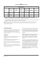
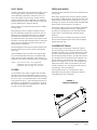
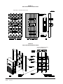
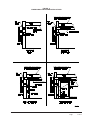
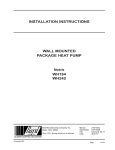
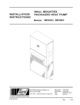
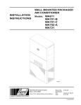
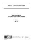
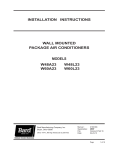
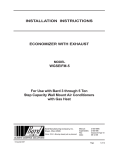
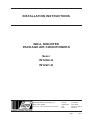
INSTALLATION INSTRUCTIONS WALL MOUNTED PACKAGE AIR CONDITIONERS Model: W12A2-A W12A1-K Bard Manufacturing Company, Inc. Bryan, Ohio 43506 Since 1914....Moving ahead just as planned. Manual:2100-509E Supersedes:2100-509D File: Volume III Tab 16 Date:08-20-12 Manual2100-509E Page 1 of 17 CONTENTS Getting Other Informations and Publications 3 Wall Mount General Information Air Conditioner Wall Mount Model Nomenclature.......4 Shipping Damage.......................................................6 General.......................................................................6 Duct Work...................................................................7 Filters..........................................................................7 Fresh Air Intake...........................................................7 Condensate Drain.......................................................7 Installation Instructions Wall Mounting Information..........................................8 Mounting the Unit........................................................8 Wiring – Main Power.................................................12 Wiring – Low Voltage Wiring.....................................12 Figures Figure 1 Figure 2 Figure 3 Figure 4 Figure 5 Figure 6 Figure 7 Start Up Requirements: R-410A..............................................13 Important Installer Note.............................................14 Service Hints.............................................................14 High & Low Pressure Switch.....................................14 Sequence of Operation.............................................14 Compressor Control Module.....................................14 Adjustments..............................................................15 Pressure Service Ports.............................................15 Troubleshooting Fan Blade Setting Dimension...................................16 Refrigerant Charge...................................................16 Pressure Table..........................................................17 Optional Field Installed Accessories.........................17 Tables Unit Dimensions........................................ 5 Fresh Air Damper...................................... 7 Mounting Instructions................................ 9 Wall Mounting Instructions...................... 10 Wall Mounting Instructions...................... 10 Common Wall Mounting Instructions.............................................. 11 Fan Blade Setting Dimensions................ 16 Manual2100-509E Page 2 of 17 Table 1 Table 2 Table 3 Table 4 Table 5 Table 6 Table 7 Table 8 Electric Heat Table.................................... 4 Electrical Specifications............................ 6 Fan Blade Dimensions............................ 16 Recommended Operating Ranges......... 16 Indoor Blower Performance.................... 16 Maximum ESP of Operation Electric Heat Only................................... 16 Pressure Table - Cooling......................... 17 Optional Accessories.............................. 17 GETTING OTHER INFORMATION and PUBLICATIONS These publications can help you install the air conditioner or heat pump. You can usually find these at your local library or purchase them directly from the publisher. Be sure to consult current edition of each standard. National Electrical Code........................ ANSI/NFPA 70 Standard for the Installation of........... ANSI/NFPA 90A Air Conditioning and Ventilating Systems Standard for Warm Air Heating.......... ANSI/NFPA 90B and Air Conditioning Systems Load Calculation for ........................... ACCA Manual J Residential Winter and Summer Air Conditioning Duct Design for .................................. ACCA Manual D Residential Winter and Summer Air Conditioning and Equipment Selection For more information, contact these publishers: ACCA Air Conditioning Contractors of America 1712 New Hampshire Avenue NW Washington, DC 20009 Telephone: (202) 483-9370 Fax: (202) 234-4721 ANSI American National Standards Institute 11 West Street, 13th Floor New York, NY 10036 Telephone: (212) 642-4900 Fax: (212) 302-1286 ASHRAE American Society of Heating, Refrigerating and Air Conditioning Engineers, Inc. 1791 Tullie Circle, NE Atlanta, GA 30329-2305 Telephone: (404) 636-8400 Fax: (404) 321-5478 NFPA National Fire Protection Association Batterymarch Park P.O. Box 9101 Quincy, MA 02269-9901 Telephone: (800) 344-355 Fax: (617) 984-7057 Manufactured under the following U.S. patent numbers: 5,485,878 and 5,301,744 Manual2100-509E Page 3 of 17 WALL MOUNT GENERAL INFORMATION AIR CONDITIONER WALL MOUNT MODEL NOMENCLATURE W 12 MODEL NUMBER A 2–A 00 X X X REVISIONS VOLTS & PHASE A-230/208/60/1 K-115/60/1 KW 00 -No KW 02 -2.2 KW 03 -3.6 KW 05 - 5.0 KW COLOR OPTIONS X-Beige 4 - Buckeye Gray VENTILATION OPTIONS X - Barometric Fresh Air Damper (Standard) B - Blank-off Plate E - Economizer (Internal) - Fully Modulating with Exhaust V - Commercial Ventilator - Motorized with Exhaust FILTER OPTIONS X - 1-Inch Throwaway (Standard) P - 2-Inch Pleated TABLE 1 ELECTRIC HEAT TABLE W12A2-A Models KW 240V A W12A1-K 208V j BTU A 120V j BTU 02 03 15.0 12,760 13.0 9,705 05 20.8 17,540 18.1 13,275 j With blower watts included Manual2100-509E Page 4 of 17 X J CONTROL MODULES E - Low Ambient Control J-Telecommunication CAPACITY 12 - 1 Ton AIR CONDITIONER X A j BTU 18.3 7,985 COIL OPTIONS X - Standard Coils OUTLET OPTIONS X - Front FIGURE 1 UNIT DIMENSIONS 32.00 30.13 17.00 Supply Air Opening Return Air Opening 17.00 2.25 Supply Air Opening 5.00 2.00* 5.00 5.00* 10.00 Return Air Opening 10.00 Top Rain Flashing Shipping Location 20.25 2.50 Optional Electrical Entrance 26.75 23.75 Side Wall Mounting Flanges (Built In) Back View Back View Return air opening is in upper field convertible position Return air opening is in lower factory standard position Built-in Rain Hood 4° Pitch 31.06 14.63 Electric Heat Heater and Filter Access 1.50 Ventilation Air 19.72 Circuit Breaker (Optional) Control Panel Electrical Entrance 46.00 Low Voltage Entrance 19.72 1.75 18.25 Front View Condenser Airflow is Blow Thru 19.88 Right Side View ( * ) Position of return air flanges are interchangeable between two positions. Factory built at 5 inches. Note: Maintain a minimum of 20 inches clearance on right side to allow access to control panel and allow proper airflow to outdoor condenser coil. Allow 15 inches on left side. MIS-2608 A (*) Position of return air flanges are interchangeable between two positions. Factory built at 5 inches. NOTE: Maintain a minimum of 20 inches clearance on right side to allow access to control panel and allow proper airflow to outdoor condenser coil. Allow 15 inches on left side. Manual2100-509E Page 5 of 17 TABLE 2 ELECTRICAL HEAT SPECIFICATIONS SINGLE CIRCUIT Rated Volts and Phase No. Field Power Circuits l Minimum Circuit Ampacity j Maximum External Fuse or Circuit Breaker k Field Power Wire Size k Ground Wire Size W12A2-A00 A03 A05 230/208-1 1 1 1 9 20 28 15 20 30 14 12 10 14 12 10 W12A1-K00 K02 115-1 1 1 20 29 30 30 10 10 10 10 Models Maximum size of the time delay fuse or HACR type circuit breaker for protection of field wiring conductors. Based on 75°C copper wire. All wiring must conform to NEC and all local codes. These “Minimum Circuit Ampacity” values are to be used for sizing the field power conductors. Refer to the National Electrical Code (latest revision), article 310 for power conductor sizing. CAUTION: When more than one field power conductor circuit is run through one conduit, the conductors must be derated. Pay special attention to note 8 of table 310 regarding Ampacity Adjustment Factors when more than 3 conductors are in a raceway. SHIPPING DAMAGE Upon receipt of equipment, the carton should be checked for external signs of shipping damage. If damage is found, the receiving party must contact the last carrier immediately, preferably in writing, requesting inspection by the carrier’s agent. GENERAL The equipment covered in this manual is to be installed by trained, experienced service and installation technicians. The refrigerant system is completely assembled and charged. All internal wiring is complete. The unit is designed for use with or without duct work. Flanges are provided for attaching the supply and return air ducts. These instructions explain the recommended method to install the air cooled self-contained unit and the electrical wiring connections to the unit. Manual2100-509E Page 6 of 17 These instructions and any instructions packaged with any separate equipment required to make up the entire air conditioning system should be carefully read before beginning the installation. Note particularly “Starting Procedure” and any tags and/or labels attached to the equipment. While these instructions are intended as a general recommended guide, they do not supersede any national and/or local codes in any way. Authorities having jurisdiction should be consulted before the installation is made. See Page 3 for information on codes and standards. Size of unit for a proposed installation should be based on heat loss/gain calculation made according to methods of Air Conditioning Contractors of America (ACCA). The air duct should be installed in accordance with the Standards of the National Fire Protection Association for the Installation of Air Conditioning and Ventilating Systems of Other Than Residence Type, NFPA No. 90A, and Residence Type Warm Air Heating and Air Conditioning Systems, NFPA No. 90B. Where local regulations are at a variance with instructions, installer should adhere to local codes. DUCT WORK FRESH AIR INTAKE All duct work, supply and return must be properly sized for the design air flow requirement of the equipment. Air Conditioning Contractors of America (ACCA) is an excellent guide to proper sizing. All duct work or portions thereof not in the conditioned space should be properly insulated in order to both conserve energy and prevent condensation or moisture damage. All units are built with fresh air inlet slots punched in the service panel. Refer to Table 6 for maximum static pressure available for duct design. All capacity, efficiency and cost of operation information as required for Department of Energy “Energyguide” Fact Sheets is based upon the fresh air blank-off plate in place and is recommended for maximum energy efficiency. Design the duct work according to methods given by the Air Conditioning Contractors of America (ACCA). When duct runs through unheated spaces, it should be insulated with a minimum of one inch of insulation. Use insulation with a vapor barrier on the outside of the insulation. Flexible joints should be used to connect the duct work to the equipment in order to keep the noise transmission to a minimum. Ducts through the walls must be insulated and all joints taped or sealed to prevent air or moisture entering the wall cavity. Some installations may not require any return air duct. It is recommended that on this type of installation that a filter grille be located in the wall. Filters must be of sufficient size to allow a maximum velocity of 400 FPM. NOTE: If no return air duct is used, applicable installation codes may limit this cabinet to installation only in a single story structure. FILTERS A one inch throwaway filter is supplied with each unit. The filter slides into position making it easy to service. This filter can be serviced from the outside by removing the service door. A 2-inch pleated filter is also available as an optional accessory. The internal filter brackets are adjustable to accommodate the 2-inch filter by bending the metal tabs holding the 1-inch filter down. There are two tabs on each side of the filter. If the unit is equipped with a fresh air damper assembly, the assembly is shipped already attached to the unit. The damper blade is locked in the closed position. To allow the damper to operate, the maximum and minimum blade position stops must be installed. See Figure 2. The blank-off plate is available upon request from the factory and is installed in place of the fresh air damper shipped with each unit. CONDENSATE DRAIN This unit employs an automatic condensate disposal system consisting of a base drain pan, drain valve and fan blade with slinger ring. A plastic drain hose extends from the evaporator drain pain at the top of the unit to the base drain pan at the bottom. At temperatures above 40°, the drain valve located between the condenser coil and fan shroud is closed allowing water to build up in the base to a height of 5/8" to 3/4". The fan blade with slinger then rotates in this water and throws the water onto the condenser coil. This disposes of the water by evaporating it on the hot condenser. At temperatures below 40°, the drain valve opens draining the base pan and preventing freeze ups that could damage the coil or fan blade. FIGURE 2 FRESH AIR DAMPER Manual2100-509E Page 7 of 17 INSTALLATION INSTRUCTIONS WALL MOUNTING INFORMATION 1. These units are secured by wall mounting brackets which secure the unit to the outside wall surface at both sides. 2. On wood frame walls, the wall construction must be strong and rigid enough to carry the weight of the unit without transmitting any unit vibration. 3. Concrete block walls must be thoroughly inspected to insure that they are capable of carrying the weight of the installed unit. MOUNTING THE UNIT 1. Two holes, for the supply and return air openings, must be cut through the wall as shown in Figure 3. 2. Locate and mark lag bolt locations, if desired. See Figure 3. 3. Hook top rain flashing under back bend of top. Top rain flashing is shipped attached to the back of the unit on the right side. Manual2100-509E Page 8 of 17 4. Position unit in opening and secure with 5/16 lag bolts; use 7/8 inch diameter flat washers on the lab bolts. 5. Secure rain flashing to wall and caulk across entire length of top. See Figure 3. 6. For additional mounting rigidity, the return air and supply air frames or collars can be drilled and screwed or welded to the structural wall itself (depending upon wall construction). Be sure to observe required clearance if combustible wall. 7. On side-by-side installations, maintain a minimum of 20 inches clearance on right side to allow access to control panel and allow proper airflow to outdoor coil. Additional clearance may be required to meet local or national codes. Manual2100-509E Page 9 of 17 FIGURE 3 MOUNTING INSTRUCTIONS FIGURE 4 WALL MOUNTING INSTRUCTIONS SEE FIGURE 3 - MOUNTING INSTRUCTIONS FIGURE 5 WALL MOUNTING INSTRUCTIONS SEE UNIT DIMENSIONS, FIGURE 1, FOR ACTUAL DIMENSIONS Manual2100-509E Page 10 of 17 FIGURE 6 COMMON WALL-MOUNTING INSTALLATIONS Manual2100-509E Page 11 of 17 WIRING – MAIN POWER WIRING – LOW VOLTAGE WIRING Refer to the unit rating plate for wire sizing information and maximum fuse or “HACR” type circuit breaker size. Each outdoor unit is marked with a “Minimum Circuit Ampacity”. This means that the field wiring used must be sized to carry that amount of current. Depending on the installed KW of electric heat, there may be two field power circuits required. If this is the case, the unit serial plate will so indicate. All models are suitable only for connection with copper wire. Each unit and/or wiring diagram will be marked “Use Copper Conductors Only”. These instructions must be adhered to. Refer to the National Electrical Code (NEC) for complete current carrying capacity data on the various insulation grades of wiring material. All wiring must conform to NEC and all local codes. 230/208, 1 phase equipment use dual primary voltage transformers. All equipment leaves the factory wired on 240V tap. For 208V operation, reconnect from 240V to 208V tap. The acceptable operating voltage range for the 240 and 208V taps are: The electrical data lists fuse and wire sizes (75°C copper) for all models, including the most commonly used heater sizes. Also shown are the number of field power circuits required for the various models with heaters. The unit rating plate lists a “Maximum Time Delay Relay Fuse” of “HACR” type circuit breaker that is to be used with the equipment. The correct size must be used for proper circuit protection and also to assure that there will be no nuisance tripping due to the momentary high starting current of the compressor motor. For wiring size and connections, refer to Wiring Manual 2100-507. Manual2100-509E Page 12 of 17 Tap 240 208 Range 253 - 216 220 - 187 NOTE: The voltage should be measured at the field power connection point in the unit and while the unit is operating at full load (maximum amperage operating condition). START UP THESE UNITS REQUIRE R-410A REFRIGERANT AND POLYOL ESTER OIL. GENERAL: REMEMBER: When adding R-410A refrigerant, it must come out of the charging cylinder/tank as a liquid to avoid any fractionation, and to insure optimal system performance. Refer to instructions for the cylinder that is being utilized for proper method of liquid extraction. 1. Use separate service equipment to avoid cross contamination of oil and refrigerants. WARNING 2. Use recovery equipment rated for R-410A refrigerant. Failure to conform to these practices could lead to damage, injury or death. 3. Use manifold gauges rated for R-410A (800 psi/250 psi low). 4. R-410A is a binary blend of HFC-32 and HFC-125. 5. R-410A is nearly azeotropic - similar to R-22 and R-12. Although nearly azeotropic, charge with liquid refrigerant. 6. R-410A operates at 40-70% higher pressure than R-22, and systems designed for R-22 cannot withstand this higher pressure. 7. R-410A has an ozone depletion potential of zero, but must be reclaimed due to its global warming potential. 8. R-410A compressors use Polyol Ester oil. 9. Polyol Ester oil is hygroscopic; it will rapidly absorb moisture and strongly hold this moisture in the oil. 10.A liquid line dryer must be used - even a deep vacuum will not separate moisture from the oil. 11. Limit atmospheric exposure to 15 minutes. 12.If compressor removal is necessary, always plug compressor immediately after removal. Purge with small amount of nitrogen when inserting plugs. TOPPING OFF SYSTEM CHARGE If a leak has occurred in the system, Bard Manufacturing recommends reclaiming, evacuating (see criteria above), and charging to the nameplate charge. If done correctly, topping off the system charge can be done without problems. With R-410A, there are no significant changes in the refrigerant composition during multiple leaks and recharges. R-410A refrigerant is close to being an azeotropic blend (it behaves like a pure compound or single component refrigerant). The remaining refrigerant charge, in the system, may be used after leaks have occurred and then “top-off” the charge by utilizing the pressure charts on the inner control panel cover as a guideline. SAFETY PRACTICES: 1. Never mix R-410A with other refrigerants. 2. Use gloves and safety glasses, Polyol Ester oils can be irritating to the skin, and liquid refrigerant will freeze the skin. 3. Never use air and R-410A to leak check; the mixture may become flammable. 4. Do not inhale R-410A – the vapor attacks the nervous system, creating dizziness, loss of coordination and slurred speech. Cardiac irregularities, unconsciousness and ultimate death can result from breathing this concentration. 5. Do not burn R-410A. This decomposition produces hazardous vapors. Evacuate the area if exposed. 6. Use only cylinders rated DOT4BA/4BW 400. 7. Never fill cylinders over 80% of total capacity. 8. Store cylinders in a cool area, out of direct sunlight. 9. Never heat cylinders above 125°F. 10.Never trap liquid R-410A in manifold sets, gauge lines or cylinders. R-410A expands significantly at warmer temperatures. Once a cylinder or line is full of liquid, any further rise in temperature will cause it to burst. Manual2100-509E Page 13 of 17 START UP IMPORTANT INSTALLER NOTE For improved start up performance, wash the indoor coil with a dishwasher detergent. SERVICE HINTS 1. Caution owner to maintain clean air filters at all times. Also not to needlessly close off supply and return air registers. This reduces airflow through the system which shortens equipment service life as well as increasing operation costs. 2. The unit is equipped with a high pressure cut out switch. 3. Check all power fuses or circuit breakers to be sure they are the correct rating. 4. Periodic cleaning of the outdoor coil to permit full and unrestricted airflow circulation is essential. HIGH & LOW PRESSURE SWITCH The W12Aà models are supplied with a remote reset high and low pressure switch. If tripped, this pressure switch may be reset by turning the thermostat off then back on again. SEQUENCE OF OPERATION HEATING – Circuit R-Y makes at thermostat pulling in compressor contactor, starting the compressor and outdoor motor. The G (indoor motor) circuit is automatically completed on any call for cooling operation or can be energized by manual fan switch on subbase for constant air circulation. On a call for heating, circuit R-W1 make at the thermostat pulling in heat contact for the strip heat and blower operation. COMPRESSOR CONTROL MODULE The compressor control module is optional on the models covered by this manual. The compressor control is an anti-short cycle/lockout timer with high and low pressure switch monitoring and alarm relay output. Adjustable Delay on Make and Break Timer On initial power up or any time power is interrupted to the unit the delay on make period begins, which will be 2 minutes plus 10% of the delay on break setting. When the delay on make is complete and the high pressure switch (and low pressure switch if employed) is closed, the compressor contactor is energized. Upon shutdown the delay on break time starts and prevents restart until the delay on break and delay on make periods have expired. Manual2100-509E Page 14 of 17 During routine operation of the unit with no power interruptions the compressor will operate on demand with no delay. High Pressure Switch and Lockout Sequence If the high pressure switch opens, the compressor contactor will de-energize immediately. The lockout timer will go into a soft lockout and stay in soft lockout until the high pressure switch closes and the delay on break time has expired. If the high pressure switch opens again in this same operating cycle the unit will go into manual lockout condition and the alarm relay circuit will energize. Recycling the wall thermostat resets the manual lockout. Low Pressure Switch, Bypass and Lockout Sequence If the low pressure switch opens for more than 120 seconds, the compressor contactor will de-energize and go into a soft lockout. Regardless the state of the low pressure switch, the contactor will reenergize after the delay on make time delay has expired. If the low pressure switch remains open, or opens again for longer that 120 seconds, the unit will go into manual lockout condition and the alarm relay circuit will energize. Recycling the wall thermostat resets the manual lockout. Alarm Relay Output Alarm terminal is output connection for applications where alarm relay is employed. This terminal is powered whenever compressor is locked out due to HPC or LPC sequences as described. NOTE: Both high and low pressure switch controls are inherently automatic reset devices. The high pressure switch and low pressure switch cut out and cut in settings are fixed by specific air conditioner or heat pump unit model. The lockout features, both soft and manual, are a function of the Compressor Control Module. ADJUSTMENTS PRESSURE SERVICE PORTS Adjustable Delay on Make and Delay on Break Timer High and low pressure service ports are installed on all units so that the system operating pressures can be observed. Pressure chart can be found later in the manual covering all models. It is imperative to match the correct pressure chart to the unit by model number. The potentiometer is used to select Delay on Break time from 30 seconds to 5 minutes. Delay of Make (DOM) timing on power up and after power interruptions is equal to 2 minutes plus 10% of Delay of Break (DOB) setting: 0.5minute(30 seconds) 1.0minute(60 seconds) 2.0minute(120 seconds) 3.0minute(180 seconds) 4.0minute (240 seconds) 5.0minute (300 seconds) DOB=123second DOM DOB=126second DOM DOB=132second DOM DOB=138 second DOM DOB=144 second DOM DOB=150 second DOM During routine operation of the unit with no power interruptions the compressor will operate on demand with not delay. Typical Settings for Dual Unit Installation: Unit No. 1: DOB set at 2 minutes, and DOM is 132 seconds. Unit No. 2: DOB set at 4 minutes, and DOM is 144 seconds. Manual2100-509E Page 15 of 17 TROUBLESHOOTING FAN BLADE SETTING DIMENSIONS TABLE 4 INDOOR BLOWER PERFORMANCE CFM @ 230V / 115V Shown in Figure 7 is the correct fan blade setting dimension for proper air delivery across the outdoor coil. Any service work requiring removal or adjustment in the fan and/or motor area will require that the dimension below be checked and blade adjusted in or out on the motor shaft accordingly. FIGURE 7 FAN BLADE SETTING DIMENSION W12Aà E.S.P. in H 2O 230V / 115V .0 .1 .2 .3 .4 Dry / Wet High Dry / Wet Low 530 485 440 390 325 465 415 365 315 270 / 500 / 460 / 425 / 375 / 300 / 425 / 400 / 350 / 300 / 265 TABLE 5 RATED CFM AND ESP RECOMMENDED AIRFLOW RANGE Model ° Rated CFM ° Rated ESP Recommended Airflow Range W12Aà 400 .10 500 - 300 ° Rated CFM and ESP on low speed tap. TABLE 3 FAN BLADE DIMENSION Model Dimension A W12Aà 1/2" R-410A REFRIGERANT CHARGE This unit was charged at the factory with the quantity of refrigerant listed on the serial plate. AHRI capacity and efficiency ratings were determined by testing with this refrigerant charge quantity. The following pressure tables show nominal pressures for the units. Since many installation specific situations can affect the pressure readings, this information should only be used by certified technicians as a guide for evaluating proper system performance. They shall not be used to adjust charge. If charge is in doubt, reclaim, evacuate and recharge the unit to the serial plate charge. Manual2100-509E Page 16 of 17 TABLE 6 MAXIMUM ESP OF OPERATION ELECTRIC HEAT ONLY Model ESP W12A2-A00 A03 A05 .35 .35 .35 W12A1-K00 K02 .35 .35 Values shown are for units equipped with STD 1" throwaway filters. Derate ESP by .15 for 2" pleated filters. TABLE 7 PRESSURE TABLE COOLING Model W12Aà Air Temperature Entering Outdoor Coil °F Return Air Temperature Pressure 75° 80° 85° 90° 95° 100° 105° 100° 115° 75 deg. DB 62 deg. WB Low Side High Side 120 291 124 310 129 332 133 355 136 379 138 405 141 432 142 460 143 490 80 deg. DB 67 deg. WB Low Side High Side 128 298 133 318 138 340 142 364 143 387 148 415 151 443 152 472 153 503 85 deg. DB 72 deg. WB Low Side High Side 132 308 138 329 143 352 147 377 150 403 153 430 156 459 157 489 158 521 Low Side Pressure +4 PSIG High Side Pressure +10 PSIG Model Description W12Aà TABLE 8 OPTIONAL FIELD INSTALLED ACCESSORIES BOP-1A Blank Off Plate X BFAD-1 Barometric Fresh Air Damper X EIFM-1 Economizer with Exhaust X CMA-28 Low Ambient Control X CRVS-1 Commercial Ventilator - Spring Return X Manual2100-509E Page 17 of 17