1
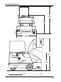
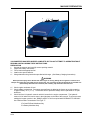
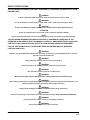
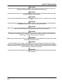
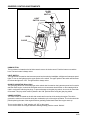
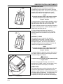
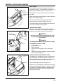
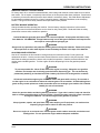
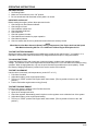
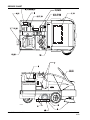
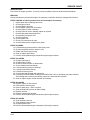
6150
POWER SWEEPER
Instructions for Use
READ THIS BOOK
This book has important information for the use and safe operation of this machine. Failure to read this book
prior to operating or attempting any service or maintenance procedure to your machine could result in injury
to you or to other personnel; damage to the machine or to other property could occur as well. You must have
training in the operation of this machine before using it.
All directions given in this book are as seen from the operator’s position at the rear of the machine.
Form
Number 56041704
American-Lincoln
6150
Revised 3/07
English
FORM NO. 56041704
-1
TABLE OF CONTENTS
MACHINE SPECIFICATIONS ...................................................................................................................... 4
MACHINE DIMENSIONS ............................................................................................................................. 6
MACHINE PREPARATION .......................................................................................................................... 7
SAFETY PRECAUTIONS ............................................................................................................................ 8
SWEEPER CONTROLS/INSTRUMENTS ................................................................................................. 10
HORN BUTTON ................................................................................................................................... 10
LIGHT SWITCH ................................................................................................................................... 10
GLOW PLUG SWITCH ........................................................................................................................ 10
CHOKE CONTROL .............................................................................................................................. 10
KEY SWITCH ....................................................................................................................................... 11
THROTTLE .......................................................................................................................................... 11
FUEL GAUGE ...................................................................................................................................... 11
FOOT BRAKE ...................................................................................................................................... 12
PARKING BRAKE ................................................................................................................................ 12
FOOT PEDAL ...................................................................................................................................... 12
FORWARD MOVEMENT ..................................................................................................................... 12
BACKWARD MOVEMENT................................................................................................................... 12
WARNING BANK ................................................................................................................................. 13
ENGINE TEMP LIGHT .................................................................................................................. 13
ENGINE OIL PRESSURE LIGHT .................................................................................................. 13
CHARGING SYSTEM LIGHT ........................................................................................................ 13
DUST CONTROL LIGHT ............................................................................................................... 13
HOPPER TEMPERATURE LIGHT ................................................................................................ 13
DUMP DOOR LIGHT ..................................................................................................................... 13
SEAT POSITION ADJUSTMENT ......................................................................................................... 14
TURN SIGNALS (OPTION) ................................................................................................................. 14
BACK-UP ALARM ................................................................................................................................ 14
BATTERY CONDITION METER .......................................................................................................... 14
FILTER SHAKER SWITCH .................................................................................................................. 15
DUST CONTROL SWITCH .................................................................................................................. 15
BROOM CONTROL LEVER ................................................................................................................ 15
SIDE BROOM LEVER ......................................................................................................................... 16
SIDE BROOM ADJUSTMENT ............................................................................................................. 16
MAIN BROOM LEVER ......................................................................................................................... 16
MAIN BROOM ADJUSTMENT ............................................................................................................ 16
HOPPER DOOR LEVER ..................................................................................................................... 17
HOPPER LIFT LEVER ......................................................................................................................... 17
DEBRIS DOOR .................................................................................................................................... 17
DUST BAFFLE ..................................................................................................................................... 18
HOPPER SAFETY ARM ...................................................................................................................... 18
HOPPER FILTER COMPARTMENT COVER ...................................................................................... 18
FILTER PANEL LATCH ........................................................................................................................ 19
HOPPER TEMPERATURE SENSOR .................................................................................................. 19
ENGINE COMPARTMENT LATCH ...................................................................................................... 19
HYDRAULIC RESERVOIR LEVER SIGHT GAUGE ........................................................................... 20
MAIN BROOM COMPARTMENT DOORS .......................................................................................... 20
SEAT COMPARTMENT COVER ......................................................................................................... 20
SEAT COMPARTMENT LATCH ........................................................................................................... 21
BATTERY CHARGING CONNECTOR ................................................................................................ 21
HELPFUL HINTS FOR SWEEPING .................................................................................................... 22
2 - FORM NO. 56041704
American-Lincoln
6150
TABLE OF CONTENTS
OPERATING INSTRUCTIONS ................................................................................................................. 23
BATTERY MACHINE OPERATION ..................................................................................................... 23
GAS/LP MACHINE OPERATION......................................................................................................... 23
INSTRUCTIONS BEFORE STARTING ............................................................................................... 24
PRE-START CHECK LIST ................................................................................................................... 24
TO START BATTERY MACHINES ...................................................................................................... 24
TO CHARGE BATTERIES ................................................................................................................... 24
TO START GAS ENGINE .................................................................................................................... 24
TO START PROPANE ENGINE........................................................................................................... 24
TO START DIESEL ENGINE ............................................................................................................... 25
TO DRIVE SWEEPER FOR TRANSPORT ......................................................................................... 25
TO SWEEP WITH THE MACHINE ...................................................................................................... 25
TO STOP SWEEPING ......................................................................................................................... 25
TO EMPTY DEBRIS HOPPER ............................................................................................................ 26
POST OPERATION CHECKLIST ........................................................................................................ 26
BATTERY CHARGING INSTRUCTIONS .......................................................................................26-27
MACHINE STORAGE .......................................................................................................................... 27
SERVICE CHART ...................................................................................................................................... 28
SERVICE INSTRUCTIONS ........................................................................................................................ 28
MAIN BROOM ..................................................................................................................................... 30
TO CHECK THE MAIN BROOM SWEEP PATTERN........................................................................... 30
TO ADJUST THE MAIN BROOM HEIGHT .......................................................................................... 30
TO REPLACE THE MAIN BROOM...................................................................................................... 30
MAIN BROOM LEVEL ADJUSTMENT ................................................................................................ 30
SIDE BROOM ...................................................................................................................................... 31
TO CHECK THE SIDE BROOM SWEEP PATTERN ........................................................................... 31
TO ADJUST THE SIDE BROOM HEIGHT ........................................................................................... 31
TO CHANGE THE SIDE BROOM........................................................................................................ 31
HOPPER .............................................................................................................................................. 32
TO CLEAN HOPPER ........................................................................................................................... 32
TO CHECK HOPPER SEALS .............................................................................................................. 32
DUST CONTROL FILTER .................................................................................................................... 32
TO CHECK THE DUST CONTROL FILTER ........................................................................................ 32
TO CLEAN THE DUST CONTROL FILTER ......................................................................................... 32
TO CHANGE THE DUST CONTROL FILTER ..................................................................................... 33
DUST FLAPS ....................................................................................................................................... 33
TO CHECK THE DUST FLAPS ........................................................................................................... 33
TO ADJUST THE DUST FLAPS .......................................................................................................... 33
BATTERY SERVICE ............................................................................................................................ 34
BATTERY CHARGING INSTRUCTIONS ............................................................................................ 34
TO CHARGE THE MOTIVE POWER BATTERIES ............................................................................. 35
American-Lincoln
6150
FORM NO. 56041704 - 3
SPECIFICATIONS
SWEEP PATH
TRAVEL SPEED
Gas/LP
0 - 5 MPH
50 inches (127 cm) with single side broom
62 inches (157.5 cm) with optional dual side brooms
Diesel
0 - 8 MPH
Battery
0 - 4 MPH
TURNING RADIUS
Left
Right
53.5 inches (136 cm)
82.0 inches (208 cm)
AISLE WIDTH FOR U-TURN
90 inches (229 cm)
MAXIMUM RATED CLIMB
Gas/LP
Diesel
Battery
8°
8°
6°
DIMENSIONS
Length 87 inches (221 cm)
Width
Height
Height w/Overhead Guard
51.50 inches (131 cm)
53.00 inches (135 cm)
77.75 inches (197.5 cm)
WEIGHT
Gas/LP
Diesel
Battery
2100 lbs. (955 kg)
2100 lbs. (955 kg)
3420 lbs. (1555 kg)
POWER SOURCE
Gas/LP
Diesel
Battery
ELECTRICAL SYSTEM
Gas/Diesel/LP
Battery-Powered
20 HP (14.933 kw), 2-cylinder liquid-cooled Kawasaki
24 HP (17.9 kw), 3-cylinder liquid-cooled Kubota
20 HP (14.933 kw), 3-cylinder liquid-cooled Kubota
36 volt system, 2.5 HP (1.87 kw) series wound drive motor
12 volts
36 volts
HYDRAULIC SYSTEM
GAS/DIESEL/LP POWERED MACHINES
The engine furnishes power through a coupling to a fixed displacement hydraulic gear pump. The pump
provides controlled oil flow to various operator controlled hydraulic valves which supply hydraulic power to
the hopper dump system and motors on the rear wheel, main broom, side broom, and vacuum fan. Hydraulic
system is protected by two filters, 100 micron and a 25 micron.
BATTERY POWERED MACHINES
The battery powered electric motor furnishes power through a coupling to a fixed displacement hydraulic gear
pump. The pump provides controlled oil flow to various operator controlled hydraulic valves which supply
hydraulic power to the hopper dump system and motors on the main broom and side broom. Hydraulic
system is protected by two filters, 100 micron and 25 micron.
STEERING
Fully Power Steering with single rear wheel steer.
BRAKES
Foot operated drum brakes on front wheels. Hand operated parking brake. When engaged, parking brake
locks the brake foot pedal in the down position.
4 - FORM NO. 56041704
American-Lincoln
6150
SPECIFICATIONS
MAIN BROOM
One-piece, disposable unit with poly core. Standard bristle type is Proex fiber. A variety of bristle types are
available. No tool broom installation or removal easily completed within five (5) minutes. Broom position can
be placed into the free float or restricted down position. Broom pattern is adjusted by control in operator’s
compartment. Offers excellent performance on rough or uneven surfaces.
Length
36 inches (91.5 cm)
Diameter
14 inches (35.5 cm)
Bristle Length
3.25 inches (8.26 cm)
SIDE BROOM
Rotary, disposable type. May be raised, lowered, and adjusted using controls in operator’s compartment.
Broom is retractable to prevent damage caused by hitting walls and racks. No tool broom installation or
removal.
Diameter
21 inches (53.4 cm)
FILTER SYSTEM
One panel filter offers a total filter area of 78 square feet (7.25 m²) and controls dust particles down to two
microns in size utilizing pre-clean baffling system. No tool panel filter installation or removal in less than two
minutes. Panel filter cleaned utilizing patented ‘beater bar’ shaker controlled by the operator. A high volume, 9
inch vacuum fan provides excellent dust control. Filter can be washed.
HOPPER
Constructed of steel, hopper provides adequate ground clearance and floating flaps.
Capacity
10 ft.³ (283 L)
Weight Capacity
700 lbs. (317.5 kg)
BROOMS CONTROLS
A separate lever raises and lowers the main broom which allows it to be set in the restricted down or free float
position. Side broom raise/lower level.
DUMPING SYSTEM
Variable dump empties debris from ground level up to 60 inches.
CONTROLS
A single foot pedal controls travel speed, forward and reverse direction. Equipped with hopper raise/lower
lever, brooms and vacuum on/off lever, filter shaker and horn buttons, key start ignition, battery condition meter (battery machines only), hour meter, fuel gauge (gas machines only), hydraulic oil level, sight gauge and
throttle control.
TIRES
Front
Rear
STANDARD EQUIPMENT
Headlights
Timed Shaker System
Hydraulic Oil Cooler
OPTIONAL EQUIPMENT
Overhead Guard
Vacuum Wand
Clogged Filter Indicator
Dual Curb Brooms
Stainless Steel Hopper
Solid Cushion Tires
American-Lincoln
6150
Gas/LP/Diesel
Two 16” Pneumatic
One 16” Pneumatic
Battery
Two 16” Solid Urethane
One 16” Solid
Dash Lights
Transport Tie Down Cutouts
Taillight
Adjustable Seat
Non-Marking Tires Solid Pneumatic
Turn Signals
Vacuumized Right Curb Broom
Arm Rests & Seat Belts
Hopper Fire Safety Sensor
Wet Sweep By-Pass
Brake Light
Strobe Amber Light
Safety Tape
Back-Up Alarm
Rear Work Light
FORM NO. 56041704 - 5
MACHINE DIMENSIONS
77.75"
197 cm
53.00"
135 cm
54.75 "
139 cm
88.00 "
223 cm
WARNING
MODEL NO.
SERIAL NO.
60.00 "
147 cm
C-0725
87.00 "
221 cm
6 - FORM NO. 56041704
American-Lincoln
6150
MACHINE PREPARATION
YOUR SWEEPER HAS BEEN SHIPPED COMPLETE, BUT DO NOT ATTEMPT TO OPERATE WITHOUT
READING AND FOLLOWING THESE INSTRUCTIONS.
PREPARATION
1.
Uncrate the sweeper and carefully remove packing material.
2.
Inspect the battery connections.
3.^ Fill fuel tank with appropriate fuel.
3.* Install motive power batteries.
4.* Charge batteries using instructions provided with charger. (See Battery Charging Instructions)
WARNING
Risk of personal injury. Never fill fuel tank while engine is running. Always be sure gasoline container and
sweeper are electrically connected prior to pouring fuel. This can easily be done by providing an insulated wire
(Permanently attached to the container) with a battery clip attached to the other end.
4.^
5.^
6.
Check engine crankcase oil level.
Check radiator coolant level. Permanent type antifreeze is added at the factory to provide protection
to approximately -35° F (-2° C). To retain this level of protection always add 1/2 part water to 1/2 part
antifreeze.
Check fluid level in hydraulic reservoir which is located in the engine compartment. The hydraulic
reservoir is full when fluid can be seen in the sight glass on the side of the reservoir. To get an accurate
reading the hopper must be in the “DOWN” position. If fluid is required add HYDRAULIC FLUID ONLY.
Use Ford Automatic Transmission Fluid Type “F”.
^For Gas/LP/Diesel Machines Only
*For Battery Machines Only
American-Lincoln
6150
FORM NO. 56041704 - 7
SAFETY PRECAUTIONS
THE FOLLOWING STATEMENTS ARE USED THROUGHOUT THIS MANUAL AS INDICATED IN THEIR
DESCRIPTIONS:
DANGER
To warn of immediate hazards which will result in severe personal injury or death.
WARNING
To warn of hazards or unsafe practices which could result in severe personal injury or death.
CAUTION
To warn of hazards or unsafe practices which could result in minor personal injury.
ATTENTION
To warn of unsafe practices which could result in extensive equipment damage.
NOTE
To give important information or to warn of unsafe practices which could result in equipment damage.
THE FOLLOWING INFORMATION SIGNALS POTENTIALLY DANGEROUS CONDITIONS TO THE
OPERATOR OR EQUIPMENT. READ THIS MANUAL CAREFULLY. KNOW WHEN THESE CONDITIONS
CAN EXIST. THEN, TAKE NECESSARY STEPS TO TRAIN MACHINE OPERATING PERSONNEL.
FOR THE SAFE OPERATION OF THIS MACHINE, READ AND UNDERSTAND ALL WARNINGS,
CAUTIONS AND NOTES.
WARNING
Machines can ignite flammable materials and vapors. Do not use with or near flammables such as: gasoline,
grain dust, solvents and thinners.
WARNING
Heavy machinery. Improper use can cause personal injury.
WARNING
Operate only when lids, doors, and access panels are securely closed.
WARNING
Use care when reversing machine in confined area.
WARNING
When servicing the machine disconnect the battery first to prevent possible injury.
WARNING
When working on the machine, empty hopper, disconnect battery, clear area of people and obstructions, use
additional people and proper procedures when lifting the machine.
WARNING
Always empty the Hopper and Disconnect Battery before doing maintenance.
WARNING
You must have training in the operation of this machine before using it. READ THE INSTRUCTION BOOK.
WARNING
Do not operate this machine unless it is completely assembled.
WARNING
Do not use this machine as a step or furniture.
8 - FORM NO. 56041704
American-Lincoln
6150
SAFETY PRECAUTIONS
WARNING
Be careful when operating the machine on a ramp or incline. Always move slowly on a ramp. Do not turn this
machine on a ramp. Do not stop and leave this machine on a ramp.
WARNING
Stop and leave this machine on a level surface. When you stop the machine, put the power switch in the “OFF”
position and Engage the parking brake.
WARNING
To prevent injury, and damage to the machine, do not lift the machine or move it to an edge of a stair or loading
dock.
WARNING
Lead acid batteries generate gases which can cause an explosion. Keep sparks and flames away from batteries.
NO SMOKING. Charge batteries only in area with good ventilation.
WARNING
Always wear eye protection and protective clothing when working near batteries. Remove all jewelry. Do not put
tools or other metal objects across the battery terminals, or the tops of batteries.
WARNING
Maintenance and repairs must be done by authorized personnel only. Tighten all fasteners. Keep adjustments
according to the specifications given in the service manual for the machine. Keep the electrical parts of the
machine dry. For storage, keep the machine in a building.
WARNING
Make sure that all labels, decals, warnings, cautions and instructions are fastened to the machine. Get new labels
and decals from American Lincoln.
WARNING
To maintain stability of this sweeper in normal operation, the counterweights, over-head guard, rear bumper
guard or any similar equipment installed by the manufacturer as original equipment, should never be removed. If
it becomes necessary to remove such equipment for repair or maintenance. This equipment must be reinstalled
before the sweeper is placed back in operation.
WARNING
The hopper could lower unexpectedly and cause personal injury. Engage the hopper safety arm before working
under the hopper.
American-Lincoln
6150
FORM NO. 56041704 - 9
SWEEPER CONTROLS/INSTRUMENTS
GLOW
PLUG
SWITCH
LIGHT
SWITCH
HOURS
0 0 0 00
1/1
0
MAINBROOM
CIRCUTBREAKERS
1
HORN
2
3
4
CHOKE
CHO
KE
THRO
TTLE
HOR
N
C0701A
FIGURE 1
HORN BUTTON
The horn button is located on the left side console next to the choke control. Push the button to sound the
horn. The horn button is always active.
LIGHT SWITCH
The light switch is located on the instrument panel and controls the headlights, taillights and instrument panel
lights. To turn on the lights press the upper portion of the switch. The upper potion of the switch will illuminate
to indicate the lights are “ON”. The light switch is always active.
GLOW PLUG SWITCH (Diesel Only)
The glow plug switch is a momentary type rocker switch that is located on the instrument panel and is used to
start the diesel engine. It should be noted that under no circumstances should Ether or other starting aids be
used in conjunction with the glow plugs. To prevent damage to the glow plug switch, do not use for more than
60 seconds. They key switch must be placed in the “ON” position before using the glow plug switch.
CHOKE CONTROL
The choke control is located on the left side console and is used to aid in starting the engine. The choke
governs the mixture of air and fuel during the combustion cycle of the engine operation. The choke should be
pulled up during the start of the engine and then gradually pushed back down after engine warm up.
To turn on the choke for “Cold” starting, pull “UP” on the control.
To turn off the choke once engine has been started gradually push the control “DOWN”.
10 - FORM NO. 56041704
American-Lincoln
6150
SWEEPER CONTROLS/INSTRUMENTS
KEY SWITCH
The keyed ignition switch is located on the instrument
panel to the right of the steering column. The key switch
is a four position switch that controls power to the sweeper systems and accessories.
O
Accessory
Position
BATTERY POWERED MACHINES
The “O ” position will shut off power to the machine propulsion and sweeping systems.
I
Start
Position
The “I” position provides power to all sweeper systems
and accessories.
C0701-1
KEY
SWITCH
C0701-1
GAS/DIESEL/LP POWERED MACHINES
The “O” position will shut off the engine.
The “I” position provides power to all sweeper systems
and accessories.
FIGURE 2
THROTTLE
The engine speed is controlled by a locking push-pull
control which is located on the operator’s compartment
side console.
PUSH BUTTON
TO RELEASE
THROTTLE
CHOK
E
THRO
TTLE
HORN
C0702
The position of the throttle determines the operating
speed of the engine. The position is variable from idle to
max engine speed and may be adjusted to suit operating
conditions.
The locking feature of the engine throttle control consists
of a rubberized push button that unlocks the control for
adjustment.
Push down on the button while positioning the control to
the desired setting, then release the button to unlock the
throttle in place.
FIGURE 3
Pull up on the throttle to increase engine speed.
1/2
Push down on the throttle to decrease engine speed.
4/4
0
FUEL
C0703/0005
C0703
American-Lincoln
6150
FUEL GAUGE
The fuel gauge is located on the instrument panel and
indicates the level of fuel in the tank. The fuel gauge
is powered by the key switch. The key switch must be
in the “I” position for the fuel gauge to work. The fuel
gauge is not included on machines that use Battery or
Liquid Propane fuel.
FIGURE 4
FORM NO. 56041704 - 11
SWEEPER CONTROLS/INSTRUCTIONS
FOOT BRAKE
The foot brake pedal is located on the floor of the
operator’s compartment to the left of the directional
control pedal.
To stop, apply foot pressure to the brake pedal.
1/2
4/4
0
HOURS
0 0 0 00
FUEL
1/10
WORK
LIGHT
LIGHTS
GLOW
PLUG
FILTER
SHAKER
DUST
CONTROL
ENGINE
SPEED
2
American-Lincoln
1
IDLE
MAIN BROOM
CIRCUT BREAKERS
1
2
3
4
5
ACC
OFF
SIDE BROOM
IGN/ON
START
6 OPTION
TO
APPLY
BRAKE
FOOT
BRAKE
PARKING BRAKE
The parking brake lever is located on the operator’s
compartment left side panel near the floor. When engaged the parking brake “locks” the foot pedal in the
down position.
-
C-0704
-
C0704
FIGURE 5
1/2
PARKING
BRAKE
0
HOURS
0 0 0 00
LIGHTS
WORK
LIGHT
GLOW
PLUG
4/4
-
FUEL
1/10
FILTER
SHAKER
DUST
CONTROL
To engage the parking brake, place the lever in the
upright position.
To disengage the parking brake, move the lever
forward.
To Adjust The Parking brake “Grab” Turn the knob
on the top of the lever.
To increase “Grab” Turn the knob in a clockwise
direction.
To decrease “Grab” Turn the knob in a counterclockwise direction.
American-Lincoln
SIDE BROOM
MAIN BROOM
O
CIRCUT BREAKERS
1
2
3
4
5
I
FOOT PEDAL
The Foot Pedal is located on the floor of operator’s
compartment to the right of the brake pedal. The
foot pedal provides control of direction/speed and
has an automatic safety feature that limits foot pedal
travel while the hopper is raised. The pedal height is
adjustable to provide for operator comfort.
6 OPTION
TO
RELEASE
BRAKE
TO GO FORWARD: Place pressure on the upper portion of the pedal. Speed increases when additional
pressure is placed on the pedal.
C-0705
C0705
TO GO BACKWARD: Put pressure on the lower portion
of the pedal. Speed increases when additional pressure
is placed on the pedal.
FIGURE 6
RE
V
ER
SE
NE
UT
HAIRPIN
COTTER
FO
RW
AR
D
ADJUSTMENT
PIN
C-0706
C0706
FIGURE 7
12 - FORM NO. 56041704
ADJUSTMENT
HOLES
RA
L
-To increase braking action while sweeper is moving
forward, gently put pressure on the lower portion of the
pedal.
-To Increase braking action while traveling in reverse,
gently put pressure on the upper portion of the pedal.
To adjust the foot pedal height for operator comfort
1. Remove the hairpin cotter from the adjustment pin.
2. Remove the adjustment pin from the foot pedal
assembly.
3. Align the holes in the lower bracket with one of the
four adjustment holes on the foot pedal to set the
foot pedal height.
4. With the holes aligned at the desired height, insert
the adjustment pin
5. Reinstall the hairpin cotter.
American-Lincoln
6150
SWEEPER CONTROLS/INSTRUMENTS
ENGINE
TEMP.
LIGHT
WARNING
BANK
HOPPER
DUMP DOOR
LIGHT
ENGINE OIL
PRESSURE
LIGHT
DUST
CONTROL
LIGHT
1/2
4/4
0
HOURS
0 0 000
1/10
CHARGING
SYSTEM
LIGHT
FUEL
+
CIRCIUT BREAKERS
1
2
3
4
5
HOPPER
TEMP.
LIGHT
-
O
6
7
I
8
C-0707-1
C0707-1
FIGURE 8
WARNING BANK
The Warning Bank is located on the instrument panel and provides the operator with six fault/status indicators
for engine and sweeper systems. The Operator should monitor the indicators while sweeping. It is very
important that the operator be familiar with the meaning of each indicator.
ENGINE TEMP LIGHT
The engine temperature light illuminates to indicate an engine cooling system fault. When
this occurs the operator must turn off the sweeper immediately and have the cooling system
serviced by a qualified service technician.
ENGINE OIL PRESSURE LIGHT
When the oil pressure drops below approximately 5 psi an automatic protection circuit shuts
down the engine and illuminates the light to indicate low engine oil pressure. When this
occurs have the sweeper serviced by a qualified service technician.
+
-
CHARGING SYSTEM LIGHT
The charging system light illuminates to indicate a charging system fault. When this occurs
the sweeper charging system is not working properly and must be serviced by a qualified
service technician.
DUST CONTROL LIGHT (option)
The Dust Control Light Illuminates to indicate that the dust control filter is clogged. When this
occurs, stop sweeping and use the filter shaker to clear dirt and debris from the filter. After
using the filter shaker continue sweeping.
HOPPER TEMPERATURE LIGHT
When the temperature of the air moving through the dust control system in the hopper
exceeds 140° F, an automatic protection feature shuts down the dust control fan and
illuminates the hopper temperature light. When this occurs shut down the sweeper and
carefully investigate for a possible fire in the hopper. The temperature switch must be
manually reset.
DUMP DOOR LIGHT
The dump door light will illuminate when the dump door is not fully open. The light warns the
operator to open the hopper dump door completely before sweeping. Do not sweep when the
light is illuminated.
American-Lincoln
6150
FORM NO. 56041704 - 13
SWEEPER CONTROLS/INSTRUMENTS
SEAT
POSITION
ADJUSTMENT
LEVER
SEAT POSITION ADJUSTMENT
The seat adjustment lever is located on the right side of
the seat base. The lever is spring loaded to the “LOCK”
position.
To adjust the seat, push “FORWARD” on the lever and
move seat to desired position then release the lever to
“LOCK” the seat in place.
TO
LOCK
TO ADJUST
C 0714
C0714
FIGURE 9
4-WAY FLASHER
SWITCH
TURN SIGNAL
SWITCH
TURN SIGNALS - 4 WAY (OPTION)
The turn signal switch is located on the steering column
and functions the same as a typical automotive turn
signal. The operator must return the lever to the centered
position after the turn has been completed.
1/2
0
HOURS
0 0 0 00
LIGHTS
WORK
LIGHT
4/4
FUEL
1/10
GLOW
PLUG
TO SIGNAL
RIGHT TURN
American-Lincoln
TO TURN
ON 4-WAY
FLASHER
TO SIGNAL
LEFT TURN
-To signal a right hand turn, move the lever to the “FORWARD” position.
-To signal a left hand turn, move the lever to the “BACKWARD” position.
-To use the 4-way Flashers pull out on the turn signal
lever.
C-0715
C0715
FIGURE 10
BACK UP ALARM (OPTION)
The backup alarm is activated by a switch in the foot
pedal and automatically emits a loud audible noise when
the machine is driven in reverse.
BATTERY CONDITION METER (Battery Power Only)
The battery condition meter is located on the right side
of the instrument panel. The condition meter indicates
the level of charge in the batteries. The batteries are
sufficiently charges when the needle stays in the green
area on the gauge while the machine is being operated.
Charge the batteries when the needle drops into the red
zone while operating the machine,
Do not operate the machine if the needle stays in the red
zone. Operating the sweeper with discharges batteries
with degrade battery life.
C-0718
C0718
FIGURE 11
14 - FORM NO. 56041704
American-Lincoln
6150
SWEEPER CONTROLS/INSTRUMENTS
FILTER
SHAKER
O
I
FILTER SHAKER SWITCH
The filter shaker switch is located on the instrument panel
below the fuel gauge. This is a momentary switch that will
activate the filter shaker motors for 20 to 30 seconds to
clear the dust control filter. The impeller fan will stop when
the filter shaker has been activated.
The filter shaker will only operate with the hopper in the
“DOWN” position. Use the filter shaker to clear the filter
when the dust control light on the warning bank illuminates
and just before dumping the hopper.
To activate the filter shaker press the upper portion of the
filter shaker switch momentarily and release. The filter
shaker will operate for 20 to 30 seconds.
C0717-1
C0717-1
FIGURE 12
DUST CONTROL SWITCH
The dust control is a two position switch that is located on
the instrument panel next to the filter shaker switch. The
switch controls the vacuum fan in the dust control system.
DUST
CONTROL
To turn on the dust control system for “NORMAL”
Sweeping, press on the top portion of the switch.
O
I
To Turn off the dust control system for sweeping in wet
conditions, press on the lower portion of the switch. This
will prevent the filter from being damaged by water pickup
while sweeping.
C0716-1
C0716-1
FIGURE 13
BROOMS
CONTROL
LEVER
BROOMS CONTROL LEVER
The brooms control lever is located on the operator’s
compartment center console. The lever is a three position
hydraulic valve that controls hydraulic power to the main
broom and side broom.
WARNING
To prevent injury, Do not turn on the brooms
with the hopper raised.
ON
OPEN
BROON
OMS CLOSE
HOPP
ER
DOOR
LOWER
RAIS
HOPP E
ER
CHO
KE
C-0719
C0719
American-Lincoln
6150
HOR
N
To turn on the main broom only, move the lever to the
forward position.
To turn on the main broom and the side broom, move the
lever fully backwards.
To turn off the brooms and provide hydraulic power to the
hopper lift system place the lever in the center position.
FIGURE 14
FORM NO. 56041704 - 15
SWEEPER CONTROLS/INSTRUMENTS
SIDE BROOM LEVER
The side broom lever is located on the right side of
the instrument panel. The side broom lever raises and
lowers the side broom. Use the brooms lever on the
operator’s center console to turn on the side broom.
SIDE BROOM
LEVER
To raise the side broom, pull the lever back into the “UP”
position.
1/2
DOWN
4/4
0
To lower the side broom, move the lever out of the
detented “UP” position and move it forward to the
“DOWN” position.
FUEL
SIDE BROOM ADJUSTMENT
The side broom lever has an adjustment for changing
the sweep height to compensate for broom wear. The
side broom adjustment is located under the right side of
the instrument panel.
UP
SIDE BROOM
To Adjust the side broom height turn the threaded knob.
SIDE BROOM
ADJUSTMENT
C0720
FIGURE 15
MAIN BROOM LEVER
The main broom lever is located on the left side of
the instrument panel. The main broom lever has three
positions and controls the main broom sweep height.
Use the brooms lever on the operator’s center console to
turn on the main broom.
MAIN BROOM
LEVER
To lower the main broom, grasp the lever and move
it to the left out of the “UP” position and place in the
“SWEEP” or “FLOAT” position.
FLOAT
HOURS
0 0 0 00
SWEEP
1/10
LIGHTS
UP
MAIN BROOM
MAIN BROOM
ADJUSTMENT
GLOW
PLUG
The “FLOAT” position is used for sweeping very uneven
surfaces only. Using the Float position will cause
premature wear on the main broom if used under normal
operating conditions for extended periods of time.
MAIN BROOM ADJUSTMENT
The main broom lever has an adjustment for changing
the sweep height to compensate for broom wear. The
main broom adjustment is located under the left side of
the instrument panel.
To Adjust the main broom height turn the threaded knob.
C-0721
C0721
WORK
LIGHT
The “SWEEP” position is used for normal sweeping and
should be used under most sweeping conditions.
FIGURE 16
16 - FORM NO. 56041704
American-Lincoln
6150
SWEEPER CONTROLS/INSTRUMENTS
HOPPER DOOR LEVER
The hopper door lever is located on the operator’s
compartment center console and is used to close and
open the hopper dump door. The lever is a three position
hydraulic valve that is spring loaded to the center
position which “HOLDS” the hopper door in position.
HOPPER
DOOR
LEVER
ON
OPEN
BROON
OMS CLOSE
HOPP
ER
DOOR
C-0722
NOTE
To provide hydraulic power to the hopper controls,
the broom control lever must be in the center
“Neutral” Position
LOWER
To ensure the door is fully open while sweeping, monitor
the Hopper Dump Door light on the Warning Bank . The
light will illuminate when the door is not fully open.
RAIS
HOPP E
ER
CHO
KE
HOR
N
C0722
To open the hopper dump door for sweeping or dumping,
push the lever forward in the “OPEN” direction until the
hopper dump door light goes out.
FIGURE 17
To close the hopper dump door for dumping or
transporting, pull the lever fully back in the “CLOSE”
direction and hold for 3 seconds or until you hear the
door close.
HOPPER
LIFT
LEVER
ON
C-0723
OPEN
BROON
OMS CLOSE
HOPP
ER
DOOR
HOPPER LIFT LEVER
The hopper lift lever is located on the operator’s
compartment center console. The lever is a three
position hydraulic valve that controls the operation of
the hopper lift system. The lever is spring loaded to
the center position which stops hopper movement and
“HOLDS” the hopper at the present position.
LOWER
RAIS
HOPP E
ER
NOTE
To provide hydraulic power to the hopper controls,
the broom control lever must be in the center
“Neutral” Position
CHO
KE
HOR
N
C0723
FIGURE 18
To raise the hopper for dumping, move the lever back to
the “RAISE” position and hold until the hopper reaches
the desired height, then release.
DEBRIS
DOOR
WARNING
To prevent injury, Do not turn on the brooms with the
hopper raised.
To lower the hopper after dumping, move the lever
forward to the “LOWER” position until the hopper is fully
lowered and seated in the sweeper, then release.
C-0724
C0724
American-Lincoln
6150
FIGURE 19
DEBRIS DOOR
The hopper debris door provides the operator with easy
access to the hopper debris compartment for refuse
disposal or visual inspection of the removable filter baffle
and hopper debris compartment. The debris door must
be closed while sweeping. Failure to close the door
completely will cause poor dust control while sweeping.
FORM NO. 56041704 - 17
SWEEPER CONTROLS/INSTRUMENTS
DUST
BAFFLE
THREADED
KNOB
DUST BAFFLE
The dust baffle is located in the hopper and may be
removed for cleaning. The dust baffle is mounted to the
hopper with two threaded knobs for easy removal.
The debris door must be opened to gain access to the
dust baffle.
Remove and clean the dust baffle when debris becomes
lodged in the baffle passages.
To remove the baffle, turn the two threaded knobs
counterclockwise and lift the baffle off the studs.
To install the baffle, position the baffle on the studs and
turn the two threaded knobs clockwise.
C-0726
C0726
HOPPER SAFETY ARM
The hopper safety arm is located near the right front
wheel well. The safety arm will prevent the hopper from
dropping unexpectedly during service/maintenance.
FIGURE 20
HOPPER
SAFETY ARM
WARNING
The Hopper Could Drop Unexpectedly And Cause
Injury. Engage The Safety Arm Before Working
Under Hopper.
WARNING
MODEL NO.
TO
ENGAGE
SERIAL NO.
6150
C-0727
C0727
FIGURE 21
DEBRIS
COMPARTMENT
COVER
HAND
HOLD
WARNING
For Safety Always Empty Hopper Before Servicing.
TO ENGAGE THE SAFETY ARM:
1. Empty hopper.
2. Set the parking brake.
3. Raise the hopper.
4. Lift safety arm to engage the slot on the hopper
frame.
5. When work has been completed, replace the safety
arm to the stowed position.
HOPPER FILTER COMPARTMENT COVER
The Hopper Filter Compartment Cover is located on the
top of the hopper and opens forward for access to the
filter compartment for service and inspection of the dust
control filter and operational hopper temp sensor.
Use the hand hold provided to open the cover.
Inspect the cover gaskets daily. Replace any cover gaskets that show signs of deterioration. Failure to maintain
the gaskets in serviceable condition will degrade dust
control at the floor and will result in less than minimal
sweeping performance.
C-0776
C0776
FIGURE 22
18 - FORM NO. 56041704
American-Lincoln
6150
SWEEPER CONTROLS/INSTRUMENTS
LIFT
FRAME TO
REMOVE
FILTER
TURN LATCH
TO RELEASE
FILTER
PANEL
LATCH
To remove the panel filter, turn the latch counter
clockwise and lift the hinged frame.
FILTER
PANEL
The panel filter can now be lifted out and cleaned or
replaced. (See “To Clean the Dust Control Filter” in
this manual).
To install the replacement panel filter, lower the
frame and turn the latch clockwise to lock the filter
in place.
C-0777
C0777
FILTER PANEL LATCH
The filter panel is located in the hopper filter
compartment and will need to be removed
periodically for cleaning or replacement. Removal
of the filter panel requires no tools. The hopper
cover must be opened to gain access to the filter
compartment. The panel filter is held in place by a
hinged frame and latch.
FIGURE 23
RESET
BUTTON
PUSH
TO
RESET
HOPPER
TEMPERATURE
SENSOR
HOPPER TEMP SENSOR (OPTION)
The temp sensor switch monitors the hopper
air temperature near the vac fan. When the
temperature of the air moving through the hopper
exceeds 140ºF the switch trips which turns off the
dust control fan and illuminates the hopper temp
light on the warning bank.
The hopper temp sensor is a resetable thermal
switch which is located in the hopper filter
compartment near the vacuum fan intake.
When the hopper temp light illuminates, carefully
investigate for a possible fire in the hopper.
The sensor will not reset until the temperature in the
hopper has dropped below 133ºF.
C 0778
C0778
FIGURE 24
ENGINE
COMPARTMENT
LATCH
To reset the temp sensor, press the reset button.
ENGINE COMPARTMENT LATCH
The engine cover encloses the entire engine,
radiator and hydraulic reservoir assembly. The
cover can be swung open to allow easy access to
the engine and hydraulics for service or inspection.
WARNING
LIFT TO OPEN
American-Lincoln
Operate Only When Lids, Doors, And Access Panels
Are Securely Closed.
To open the cover, lift the cover latch lever up.
Swing the cover open.
The cover will latch automatically when the cover is
closed. After closing the engine cover, check to be
certain the latch has fully engaged.
C-0779
C0779
American-Lincoln
6150
FIGURE 25
FORM NO. 56041704 - 19
SWEEPER CONTROLS/INSTRUMENTS
HYDRAULIC
SIGHT
GAUGE
HYDRAULIC RESERVOIR LEVEL SIGHT GAUGE
The sight gauge is located on the side of the hydraulic
reservoir in the engine compartment. The sight gauge is
used to indicate the level of fluid in the reservoir. Fluid
level must be visible in the sight gauge when the hopper
is in the down position.
MAIN BROOM COMPARTMENT DOORS
The main broom compartment doors are located behind
the front tires on both sides of the sweeper. The doors
provide access to the main broom for service or inspection.
WARNING
Operate Only When Lids, Doors, And Access Panels
Are Securely Closed.
C-0728
C0728
FIGURE 26
Open the right side door to remove or replace the main
broom. The right side door is an integral part of the main
broom drive system and must be closed for operation.
Open the left side broom door for inspection. Check the
drive hub for banding and shrink wrap which have a
tendency to get tangled in the broom driver.
American-Lincoln
MAIN BROOM
COMPARTMENT
LATCH
C-0729
C0729
To open the main broom door, reach inside the hole in
the door and lift up on the latch handle.
The door latch will automatically engage when the door
is closed.
SEAT COMPARTMENT COVER
The seat compartment cover opens to allow easy access
to various components which will need to be inspected or
serviced periodically. The cover opens forward and has
a safety latch to hold the cover in the open position.
LIFT TO OPEN
FIGURE 27
WARNING
Lead acid batteries generate gases which can cause
an explosion. Keep sparks and flames away from
batteries. NO SMOKING. Charge batteries only in
area with good ventilation and keep the seat cover
open to vent explosive hydrogen gas.
WARNING
MODEL NO.
SERIAL NO.
American-Lincoln
On battery powered machines the compartment below
the seat contains the charging connector for the
batteries. Use the safety latch to hold the cover open
while charging the batteries.
On Gas/Diesel/LP powered machines the seat
compartment contains the fuel tank.
c0731/0005
C0731
FIGURE 28
20 - FORM NO. 56041704
American-Lincoln
6150
SWEEPER CONTROLS/INSTRUMENTS
TRABA DEL COMPARTIMIENTO
DEL ASIENTO
LIFT TO HOLD
SEAT COVER
OPEN
SEAT COMPARTMENT LATCH
The seat compartment latch is located under the seat
compartment cover and is used to hold the cover open
while charging the batteries.
To hold the seat compartment cover open, lift the latch to
the vertical position and release the cover to rest on the
latch.
C0732
C0732
FIGURE 29
TO DISCONNECT
BATTERIES
FOR CHARGING
BATTERY
CHARGING
CONNECTOR
C0730
American-Lincoln
6150
FIGURE 30
BATTERY CHARGING CONNECTOR
The batteries on battery powered machines are
connected to the machine through a heavy duty two
conductor connector. The connector allows an easy
method of disconnecting power to the machine for
service or charging of the batteries.
Plug the charger into the connector to charge the
batteries.
WARNING
Disconnecting the battery connector with the key
switch in the “I” position will cause sparks that
could ignite explosive hydrogen gas generated by
the batteries. To prevent serious injury or possible
property damage, turn key switch to “O” position
before disconnecting battery cable from machine
charging or service.
FORM NO. 56041704 - 21
HELPFUL HINTS FOR SWEEPING
SIDE AISLES
MAIN AISLE
P4134/0001
P4134
SIDE AISLES
FIGURE 31
HOW TO SWEEP
The sweeper is intended for use on hard relatively flat surfaces such as cement, asphalt, and wood block
floors. Exercise care when maneuvering to keep wheels from dropping off curbs or into pot holes. Do not
sweep over obstructions.
WARNING
Do Not Turn The Steering Wheel Sharply When The Machine Is In Motion. The Sweeper Is Very
Responsive To Movement Of The Steering Wheel. Do Not Make Sudden Turns.
The sweeper is designated for dry sweeping conditions. Wet clay and muddy type material will adhere to
surface of sweeping chamber and hopper. Sweeping performance will degrade if these surfaces are not kept
clean. Large heavy objects such as bricks, large stone, and iron parts should not be swept. Damage to the
main broom or other sweeping system components is possible. String, rope, wire or metal strapping longer
than 18 inches should not be swept. These items have a tendency to wrap around moving parts. This can
cause damage or degrade sweeping performance.
SWEEPING GUIDELINES
In actual sweeping, there is no single pattern that can be set forth in this manual. Each installation has its
own conditions, and the operator can readily set his own pattern using these guidelines.
-Pick up large debris before sweeping with machine.
-Use the machine to sweep debris from narrow aisles into main aisle.
-After the machine has made a sweeping run, push the filter shaker control button for 20 to 30 seconds, the
filter shakers will unload accumulated dust from the filter media.
-Sweep debris from main aisle.
-Overlap of broom paths when sweeping. This will eliminate leaving dirty patches.
-Empty hopper when the sweeper leaves debris, while sweeping.
-Sweep in straight paths. Do not bump posts. Do not scrape the sides of the machine.
NOTE
Replace main broom when bristles are worn to 1.75 inch (3.5 cm) length. To order replacement
brooms, see appropriate PARTS LIST and follow instructions in the MAIN BROOM section of this
manual. Replace side broom when bristles fail to sweep debris into the path of the main broom. To
order replacement brooms, see appropriate PARTS LIST and follow instructions in the SIDE BROOM
section of this manual.
22 - FORM NO. 56041704
American-Lincoln
6150
OPERATING INSTRUCTIONS
SWEEPING VARIOUS TYPES OF DEBRIS
For heavy sand, dirt, or excessive scattered debris, travel slowly with machine to allow main broom to deliver
best results. Do not expect a completely clean surface on the first pass under these conditions. Sometimes it
is necessary to have extra broom pressure where debris is excessively heavy. See “Main Broom Adjustment”
for information on adjusting broom to a “heavy” sweeping pattern. Material that adheres to the sweeping
surface: This type of wet or sticky material will require more broom pressure.
BATTERY MACHINE OPERATION
Charge the batteries after operating the machine. See the battery charging instructions in this manual.
Use the pre-start check-list and follow the service chart for daily check points. Read and follow the safety
precautions to assure safe, trouble free operation.
WARNING
Lead acid batteries generate gases which can cause an explosion. Keep sparks and flames away
from batteries. NO SMOKING. Charge batteries only in area with good ventilation and keep the seat
cover open to vent explosive hydrogen gas.
WARNING
Always wear eye protection and protective clothing when working near batteries. Remove all jewelry.
Do not put tools or other metal objects across the battery terminals or the tops of the batteries.
GAS/LP/MACHINE OPERATION
See the LP instructions in this manual for fueling and service instructions on the LP fuel system and
replacement of tanks. Use the pre-start check-list and follow the service chart for daily check points. Read
and follow the safety precautions to assure safe, trouble free operation. Gasoline powered machines use
regular grade unleaded gasoline. Turn the engine off before dispensing fuel into the gasoline powered
machine.
WARNING
To prevent possible fire: Never fill fuel tank while engine is running. Always be sure gasoline
container and sweeper are electrically grounded before dispensing gas. This can be done by
permanently attaching an insulated wire with a battery clip on the end to the gasoline container.
WARNING
All internal combustion engines give off harmful fumes and gases while running. Do not start or
run the engine in an enclosed area where the exhaust gases can accumulate. Avoid breathing these
gases as they contain poisonous carbon monoxide which can endanger your health or life if inhaled
steadily for even a few minutes.
WARNING
Check for gas odor before and during starting operations. If gas odor is noticed, stop and check for
leaks or component malfunctions in the fuel system. Check fuel supply hoses for proper connection
and signs of abrasion. Do not start engine when gas odor is present.
WARNING
Keep cigarettes, sparks, and open flame away when working on LP equipment, use caution when
inspecting for gas leaks or when LP tanks are present.
WARNING
Do not run engine in an enclosed area. Exhaust gases contain carbon monoxide, an odorless and
deadly poison. Do not operate the engine without adequate ventilation.
American-Lincoln
6150
FORM NO. 56041704 - 23
OPERATING INSTRUCTIONS
BEFORE STARTING
1. Set Parking Brake.
2. Make sure all controls are in the “Off” position.
3. Be sure accelerator and directional control pedal is in neutral.
PRE-START CHECK LIST
Before starting the engine, perform these pre-start checks.
1. Check engine air filter element indicator.
2. Check engine oil level.
3. Check radiator coolant level.
4. Check hydraulic fluid level.
5. Check fuel level.
6. Check all systems for leaks.
7. Check brakes and controls for proper operation.
8. Check broom patterns
9. Check to ensure that all covers, panels and access doors are securely closed.
NOTE
When Machine Has Been Stored In Below Freezing Temperatures, Run Engine At A Low Idle Speed
With Machine Standing Still For 5 To 10 Minutes To Warm Engine And Hydraulic Oil.
TO START BATTERY MACHINES
Starting the battery powered models is accomplished by turning the key switch to the “I” (on) position. It is
important to note that the batteries should be fully charged and serviced prior to using the machine.
TO CHARGE BATTERIES
Charge the batteries at the end of each day or when the battery condition meter indicates low battery
voltage. The batteries need to be charged when the needle stays in the “red” zone while the machine is being
operated. When charging batteries, only use the quick disconnect provided ensure correct polarity. Follow
the “Battery Charging Instructions” provided in the service section of this manual.
TO START GAS ENGINE
Use the choke in extremely cold temperatures, (under 32 F. or 0 C.),
1. Pull choke if needed.
2. Adjust the throttle to a low engine speed setting.
3. Turn key to “START” position until engine starts, then release. (The key switch will return to the “ON”
position.)
4. Push in choke after engine starts running (If used).
TO START PROPANE ENGINE
Perform these checks in addition to the Pre-Start check list.
1. Check connections for leaks
2. Open the LP storage tank valve.
3. Check the regulator. Momentarily press fuel primer on the regulator cover to bleed air out of the system.
4. Adjust the throttle to a low engine speed setting.
5. Turn key to “START” position until engine starts, then release. (The key switch will return to the “ON”
position.)
24 - FORM NO. 56041704
American-Lincoln
6150
OPERATING INSTRUCTIONS
TO START DIESEL ENGINE
When starting the diesel engine, it should be noted that under no circumstances should Ether or any other
starting fluids be used in conjunction with the glow plugs. Do not use the glow plugs for more than 60 seconds
at a time or damage to the plugs may result. They key switch must be placed in the “ON” position before using
the glow plug switch.
1. Perform the Pre-Start checks found previously in this manual.
2. Turn the ignition switch to the “ON” position and place the throttle in a high engine speed setting.
3. Push and hold the glow plug switch for approximately 30 seconds. Under cold starting conditions, the
glow plug switch may be held longer but do not hold the switch for more than 60 seconds to prevent
damage to the glow plugs.
4. Turn the key switch to the start position and hold until engine starts. If the engine does not start
immediately, release the key switch after 15 seconds to prevent damage to the starter.
5. Release the glow plug switch when the engine starts.
TO DRIVE SWEEPER FOR TRANSPORT
1. Ensure the main broom lever and the side broom lever are in “UP” position with all other sweeping
controls in the “OFF” position.
2. Release the parking brake.
3. Adjust the throttle to a medium to high engine speed setting.
4. Push forward on the foot pedal to start the sweeper moving.
5. Vary your foot pressure on the pedal to obtain the desired speed.
6. To stop, allow the foot pedal to return to the centered position. (Pedal will return to neutral when pressure
is released)
WARNING
Do Not Turn The Steering Wheel Sharply When The Machine Is In Motion. The Sweeper Is Very
Responsive To Movement Of The Steering Wheel. Do Not Make Sudden Turns.
WARNING
Machines Can Ignite Flammable Materials And Vapors. Do Not Use With Or Near Flammables Such As:
Gasoline, Grain Dust, Solvents And Thinners.
TO SWEEP WITH THE MACHINE
1. Move the broom control lever to the “ON” position.
2. Lower the side and main broom to the floor. (The main broom control may be placed in either the “FLOAT”
or “SWEEP” position).
3. Press the Dust Control Switch to the “ON” position.
4. Push forward on directional control pedal to place machine in motion.
5. Vary foot pressure on the directional control pedal to obtain desired travel speed.
6. Read the “Helpful Hints for Sweeping” in this manual for tips on maximizing sweeping performance.
WARNING
Stop And Leave This Machine On A Level Surface. When You Stop The Machine, Put The Key Switch
In The “OFF” Position And Engage The Parking Brake.
TO STOP SWEEPING
1. Allow directional control pedal to return to neutral (centered) position. (Pedal will automatically return to
neutral when foot pressure is released.)
2. Depress the foot brake.
3. Press the Dust Control Switch to the “OFF” position..
4. Place the broom controls (Side and Main) in the “UP” position.
5. Move the Broom Control lever to the center “OFF” position.
6. Adjust the throttle to a low engine speed setting.
7. Set parking brake.
American-Lincoln
6150
FORM NO. 56041704 - 25
OPERATING INSTRUCTIONS
TO EMPTY DEBRIS HOPPER
1. Adjust the throttle to a medium to high engine speed setting.
2. Engage parking brake.
3. Move the Hopper Dump door lever to the “CLOSE” Position until door is closed.
4. Move the hopper lift lever to the “RAISE” position until the hopper reaches the desired height.
5. Disengage Parking Brake.
6. Drive forward slowly with the hopper raised to clear refuse container before opening the hopper dump
door.
7. Engage Parking Brake.
8. Push the hopper dump door lever forward to the “OPEN” position. This will allow debris in the hopper to
fall out into the refuse container.
9. Move the hopper dump door lever to the “CLOSE” Position until door is closed.
10. Disengage Parking Brake. •
11. Drive in reverse slowly to clear the refuse container.
12. Engage Parking Brake.
13. Move the hopper lift lever forward to the “LOWER” position and hold until hopper is seated in place.
14. Move the hopper dump door lever to the “OPEN” position until the dump door opens.
WARNING
Do Not Turn off the engine with the hopper in the lifted position.
NOTE
After Stopping The Engine, Perform These Post Operation Checks.
POST OPERATION CHECK LIST
1. Clean debris hopper.
2. Check sweeping brooms for wear or damage.
3. Check all flaps for wear, damage and adjustment.
4. Fill the fuel tank.
5. Check all systems for leaks.
6. Close the LP storage tank valve. (LP Powered machines only)
WARNING
The Gasoline Tank Fill Cap Is Located Behind The Drivers Seat, Do Not Mistake The Hydraulic Reservoir For The
Gasoline Tank.
BATTERY CHARGING INSTRUCTIONS (Battery powered Machines Only)
Charge the batteries at the end of each day or when the battery condition meter indicates low battery
voltage. The batteries need to be charged when the needle stays in the “red” zone while the machine is being
operated. When charging the batteries, only use the quick disconnect provided in ensure correct polarity.
Check the liquid level in the batteries at least once a week and add water when low. Use only distilled
water. Fill the batteries after charging the batteries to prevent electrolyte from spilling over on the tops of the
batteries during the charging process.
WARNING
The use of an extension cord with the charger should be avoided. Risk of fire and electrical shock
is possible if the wrong type or size extension cord is used. If an extension cord must be used, only
use a three conductor number 12 AWG cord with ground, properly wired, in good electrical condition
and keep it as short as possible. Locate all cords so that they cannot be stepped on, tripped over, or
otherwise subjected to damage or stress.
26 - FORM NO. 56041704
American-Lincoln
6150
OPERATING INSTRUCTIONS
BATTERY CHARGING INSTRUCTIONS - cont.
WARNING
Verify that the AC power source to which the charger is to be connected is capable of supplying the
current specified on the charger nameplate.
WARNING
Keep all charger ventilation holes at least 2 inches away from walls or other objects. Do not allow
vent holes to become obstructed.
WARNING
Do not operate charger that has been damages or shows physical signs of damage. Have charger
serviced by a qualified professional repair person.
WARNING
Lead acid batteries generate gases which can cause an explosion. Keep sparks and flames away
from batteries. NO SMOKING. Charge batteries only in area with good ventilation and keep the
top cover open while charging batteries. Do not disconnect the charger from the batteries before
disconnecting the AC power cord. Disconnecting the battery cable with the charger plugged in could
cause an explosion.
WARNING
Disconnecting the battery connector with the key switch in the “I” position will cause sparks that
could ignite explosive hydrogen gas generated by the batteries. To prevent serious injury or possible
property damage, turn key switch to “O” position before disconnecting battery cable from machine
for charging or service.
MACHINE STORAGE
GASOLINE POWERED MACHINES
Machines to be stored over 30 days should be completely drained of fuel to prevent gum deposits forming on
essential carburetor parts, fuel filter and tank.
The use of a fuel additive, such as STA-BIL, or an equivalent, will minimize the formation of fuel gum deposits
during storage. Such an additive may be added to the gasoline in the fuel tank of the engine.
The following procedure should be used to prepare the machine for storage:
1. All fuel should be removed from the tank. Run the engine until it stops from lack of fuel.
2. While engine is still warm, drain oil from the crankcase. Refill with fresh oil.
3. Remove spark plug, pour approximately 1/2 ounce (15 grams) of engine oil into cylinder and crank slowly
to distribute oil. Replace spark plug.
4. Store in a clean and dry area.
BATTERY POWERED MACHINES
All wet batteries will slowly discharge on standing and will discharge much faster when warm than when cold.
At normal temperature of 80ºF (26ºC) loss of capacity by self-discharge, starting with a fully charged battery,
may amount to an average of .001 specific gravity per day over a 30 day period. The battery should be given
a booster charge when a specific gravity falls .040.
Do not discharge the batteries excessively. Excessive discharge can cause polarity reversal of the individual
cells in the battery which will lead to complete failure of the batteries.
Use a hydrometer to monitor the specific gravity of the individual cells in the batteries. When checking the
specific gravity of the batteries, you should not see a large difference between individual cells. The batteries
may need to be replaced if the battery shows a significant difference of specific gravity between the cells.
The specific gravity of the electrolyte should measure 1.285 when fully charged.
Check items for proper operation. If service is required, please contact an authorized
American-Lincoln distributor.
American-Lincoln
6150
FORM NO. 56041704 - 27
SERVICE CHART
9,10,20,32,27
12,14,34
8
4,21
3,36,37,38
2,17,19
1,16
11,20
13,22
13
7
8
23,25
WARNING
MODEL NO.
SERIAL NO.
American-Lincoln
C1251
5
5
15
28 - FORM NO. 56041704
6
American-Lincoln
6150
SERVICE CHART
SERVICE CHART
Check items for proper operation. If service is required, please contact an authorized Alto distributor.
BREAK-IN
During initial break-in period of the engine, the crankcase oil and filter should be changed after 20 hours.
EVERY 8 HOURS or DAILY operation check and clean/adjust if necessary:
1. Inspect panel filter for damage and clean.
2. Check engine oil level
3. Check hydraulic fluid level
4. Check radiator cooling fins for blockage
5. Check all flaps for wear or damage
6. Check brooms for wear or damage, adjust as required
7. Check brake pedal and parking brake
8. Check battery electrolyte level.
9. Check belt tension.
10. Check coolant level
11. Check LPG connections for odor.
12. Check all fluid system components for leaks.
EVERY 50 HOURS
13. Lubricate dump system and drive wheel pivot points
14. Check all hydraulic hoses for wears or cuts.
15. Rotate main broom (end for end)
16. Clean or replace panel filters
17. Perform recommended engine maintenance (See engine manual)
EVERY 100 HOURS
18. Change crankcase oil.
19. Change engine oil filter.
20. Check fuel hose for leaks or deterioration.
21. Check radiator hoses and clamps.
22. Lubricate steering yoke pivot bearings.
23. Lubricate front wheel bearings.
24. Lubricate all moving joints.
25. Check brake pads for wear and adjustment.
26. Lubricate all “DAN HOUSER” bushings with NAPA #765-1363 (or equivalent) anti-seize lubricant.
The bushings are located on the steering, hopper lift, and dump door cylinders.
27. Clean or replace engine air filter element as necessary.
EVERY 250 HOURS
28. Replace engine air filter element
29. Flush radiator coolant system
30. Remove spark plugs - clean or replace
31. Clean and lubricate governor & choke linkage
32. Replace fuel filter
33. Replace hydraulic filter element
34. Perform recommended engine maintenance (See engine manual)
EVERY 500 HOURS
36. Clean hydraulic reservoir
37. Clean hydraulic intake strainer
38. Change hydraulic fluid
39. Perform recommended engine maintenance (See engine manual)
American-Lincoln
6150
FORM NO. 56041704 - 29
SERVICE INSTRUCTIONS
SWEEPING SYSTEM SERVICE
MAIN BROOM
To prevent the broom from “setting” in one direction and to provide the maximum life of the broom it is
recommended that the broom be turned end for end periodically.
TO CHECK THE MAIN BROOM SWEEP PATTERN
Check the main broom sweep pattern after changing the broom or when poor sweeping performance is
encountered while sweeping.
1. While the machine is not moving, lower the main broom to the “SWEEP” position and let machine sweep
in one spot for a short period of time.
2. Before moving machine, raise main broom lever to the “UP” position and move the sweeper forward
enough to see the pattern left by the main broom bristles on the floor.
3. Check the width of the pattern on the floor to determine if the main broom requires adjustment.
-A normal sweep pattern left on the floor will be between 1 and 2 inches wide.
-A pattern that is more than 2 inches wide indicates the broom linkage needs to be adjusted “UP”
-A pattern that is less than 1 inch wide indicates the broom linkage needs to be adjusted “DOWN”
TO ADJUST THE MAIN BROOM HEIGHT
When changing the sweep height adjustment it is recommended that the bolt be adjusted 1 turn at a time,
After adjustment, re-check the sweep pattern to determine if further adjustment is necessary.
-Turn the adjustment knob counter-clockwise to INCREASE the sweep pattern width.
-Turn the adjustment knob clockwise to DECREASE the sweep pattern width.
TO REPLACE THE MAIN BROOM
The Main Broom should be replaced when the bristles become worn to less than 2”. The main broom is held
in place by the right side broom door. This feature provides for easy removal and installation of the main
broom without the need for special tools or equipment. Follow the instructions below for main broom removal
& replacement.
1. Park sweeper on a smooth level surface, engage parking brake, turn key switch “OFF”, place the main
broom lever in the “SWEEP” position.
2. Lift the door latch to open the right side broom door.
3. Swing the broom drive idler hub out to clear the main broom.
4. Remove the broom from the broom compartment.
5. Install the replacement broom. Pay special attention to the slots on the broom, it may be necessary to
rotate the broom so the tabs on the drive hub align with the slots on the broom.
6. Swing the idler hub to engage the main broom and close the access door. Check the door latch for proper
engagement when closed.
7. Check the Main Broom sweep pattern and adjust as necessary.
MAIN BROOM LEVEL ADJUSTMENT
The main broom level is factory set and should not need adjustment. If the level becomes out of adjustment
and the broom bristle contact pattern is not an even 2” to 3” wide, the broom arm lift frame will need to be
adjusted. The frame is supported by two plates located inside the broom doors. The carriage bolts (part
number 2-00-05187) that secure the plates to the frame will need to be loosened. The frame can then be
leveled and the bolts retightened.
30 - FORM NO. 56041704
American-Lincoln
6150
SERVICE INSTRUCTIONS
LOCK PIN
FLOOR
CONTACT
AREA
10
FORWARD
3
C-0740
C0740
SIDE
BROOM
FIGURE 32
SIDE BROOM
The Side Broom sweeping angle is not adjustable however the height of the side brooms can be adjusted to
compensate for wear as the broom becomes worn from use. Always check and adjust the sweep pattern after
changing the side broom.
TO CHECK THE SIDE BROOM SWEEP PATTERN
1. Park the machine on a smooth level surface.
2. Place the Side Broom Lever in the “DOWN” position.
3. Move the Brooms Control Lever to the “ON” position.
4. While staying in place allow the side broom to sweep for a short period of time. (Allow enough time for
the side brooms to leave a clean footprint on the floor).
5. Place the Side Broom Lever in the “UP” position.
6. Move the Brooms Control lever to the “OFF” position.
7. Back the sweeper away from the area where the Pattern was left. •
8. Turn Key Switch to the “OFF” position and engage parking brake.
9. Leave operator’s compartment and check the pattern to determine the Floor Contact area.
10. Determine if adjustment to the side brooms height is necessary by examining the floor contact area the
broom should contact the floor as shown in figure 34 above.
Adjust the side broom height if the contact area on the floor does not match the diagram.
TO ADJUST THE SIDE BROOM HEIGHT
Turn the side broom adjustment knob to change the side broom sweep height. Re-check for proper sweep
pattern after adjustment.
-Turn the adjustment knob counter-clockwise to INCREASE the sweep pattern width.
-Turn the adjustment knob clockwise to DECREASE the sweep pattern width.
TO CHANGE THE SIDE BROOM
Change the side brooms when the bristles become worn to less than 3 inches length.
1. Park Machine on a smooth level surface, turn key switch to “OFF” Position and engage Parking Brake.
2. Place the side brooms lever in the “UP” Position.
3. Remove the lock pin that holds the broom flange to the motor shaft.
4. Disassemble the flange from the broom by removing the screws that hold the flange to the broom.
5. Assemble the flange to the replacement Broom and fasten using the hardware removed.
6. Install the replacement broom on the shaft and insert the lockpin.
American-Lincoln
6150
FORM NO. 56041704 - 31
SERVICE INSTRUCTIONS
HOPPER
The hopper houses the debris
compartment, the dust control
filter and the removable
dust baffle. For maximum
performance and service life,
keep the hopper clean and
inspect the seals and flaps
daily. Clean the hopper prior
to parking the sweeper at the
end of the day. A clean hopper
will make inspecting the flaps
and seals much easier and will
prevent premature deterioration
of hopper components. Do not
leave the hopper full of debris
while in storage or when parked
for extended periods of time
TO CLEAN HOPPER
Once the hopper has been
emptied the insides of the
hopper should be rinsed out
with water.
FILTER
COMPARTMENT
DEBRIS
COMPARTMENT
DUST
BAFFLE
HOPPER
SEALS
C-0739
C0739
FIGURE 33
TO CHECK HOPPER SEALS
The Hopper seals are important to positive dust control while sweeping. Damaged seals will reduce vacuum
pressure at the broom. Inspect for cuts, tears and proper positioning of the seal material. Replace all seals
that become damaged.
DUST CONTROL FILTER
The dust control filter should be checked daily for damage and cleaned if necessary. A damaged filter must
be replaced to prevent damage to other dust control system components. Inspect the filter for tears in the
filter media or excessive dirt lodged in the pleats. A tear in the filter media will allow dirt to pass through the
filter and can be easily seen as a dirty patch on the top side on the filter. Cleaning the filter is necessary when
the filter shaker fails to adequately clean the pleats.
TO CHECK THE DUST CONTROL FILTER
1. Park the sweeper on a smooth level surface. Turn the key switch to the “O” position and engage the
parking brake.
2. Raise the hopper lid for access to the filter compartment.
3. Turn the latch, lift the filter frame and remove the filter.
4. Inspect the panel filter for tears and clean or replace if necessary.
5. Reinstall the filter, lower the filter frame and engage the filter latch.
6. Close the hopper cover.
TO CLEAN THE DUST CONTROL FILTER
Clean the dust control filter when the shaker fails to adequately clear the filter. The filter can be cleaned with
compressed air not to exceed 100psi.
To clean the filter with compressed air, apply the compressed air to the top of the panel to backflush the
lodged dirt from the filter pleats. Be careful to not damage the filter media while cleaning. The filter can
be cleaned with a solution of soap and water. If this cleaning method is used do not use the filter until it is
completely dried.
32 - FORM NO. 56041704
American-Lincoln
6150
SERVICE INSTRUCTIONS
1/16"
SET DOOR FLAP
EVEN WITH FLOOR
P4488A
FIGURE 34
TO CHANGE THE DUST CONTROL FILTER
Change the filter panel when damage is evident.
1. Park the sweeper on a smooth level surface. Turn the key switch to the “O” position and engage the
parking brake.
2. Open the hopper compartment cover to gain access to the filter compartment.
3. Turn the latch on the hinged frame counter-clockwise and lift the frame.
4. Remove the filter panel.
5. Install replacement filter, lower the hinged frame and engage the latch.
6. Lower the filter compartment cover.
DUST FLAPS
The dust flaps are very important to sweeping and dust control and are susceptible to damage and should be
inspected daily and maintained in good condition.
TO CHECK THE DUST FLAPS
The dust flaps are used on the wheel well, broom chamber, and broom door. Inspect the flaps daily and
replace any flap that shows signs of wear or deterioration. All flaps should be replaced when worn or
damaged to the point that they can no longer perform their normal function. The adjustable flaps have slotted
mounting holes to facilitate adjustment.
TO ADJUST THE DUST FLAPS
Adjust the flaps so there is a 1/8” to 1/16” Gap between the floor and the bottom edge of the flaps. The rear
flap adjustment is 1/16” (16 cm.) above the floor.
1. Park Sweeper on a smooth level surface and engage the Parking Brake.
2. Loosen the Flap retaining screws and adjust the flap to clear the floor and leave a 1/16” to 1/8” Gap.
3. Tighten Flap retaining screws while holding flap in position.
4. Drive sweeper on a smooth surface and recheck the flaps for proper floor clearance.
American-Lincoln
6150
FORM NO. 56041704 - 33
SERVICE INSTRUCTIONS
BATTERY SERVICE INSTRUCTIONS
STARTER BATTERY (Gas/LP/Diesel Powered Machines Only)
The starter battery is located in the engine compartment on Gas/LP/Diesel powered machines. Keep the top
of the battery clean and dry. Keep the terminals and connectors clean. To clean the tops of batteries, use
a damp cloth with a weak solution of ammonia or bicarbonate of soda solution. To clean the terminals and
connectors, use a terminal and connector cleaning tool.
ATTENTION
Never allow the soda solution to enter the cells. This will permanently discharge the battery.
BATTERY CHARGING INSTRUCTIONS (Battery powered Machines Only)
Charge the batteries at the end of each day or when the battery condition meter indicated low battery
voltage. The batteries need to be charged when the needle stays in the “red” zone while the machine is being
operated. When charging batteries, only use the quick disconnect provided. Use the quick disconnect to
insure correct polarity.
34 - FORM NO. 56041704
American-Lincoln
6150
SERVICE INSTRUCTIONS
BATTERY SERVICE INSTRUCTIONS
BATTERY CHARGING INSTRUCTIONS - cont.
Check the liquid level in the battery at least once a week and add water when low. Use only distilled water.
Fill the batteries after charging the batteries to prevent electrolyte from spilling over on the tops of the
batteries during the charging process.
WARNING
The use of an extension cord with the charger should be avoided. Risk of fire and electrical shock
is possible if the wrong type or size extension cord is used. If an extension cord must be used, only
use a three conductor number 12 AWG cord with ground, properly wired, in good electrical condition
and keep it as short as possible. Locate all cords so that they cannot be stepped on, tripped over, or
otherwise subjected to damage or stress.
WARNING
Verify that the AC power source to which the charger is to be connected is capable of supplying the
current specified on the charger nameplate.
WARNING
Keep all charger ventilation holes at least 2 inches away from walls or other objects. Do not allow
vent holes to become obstructed.
WARNING
Do not operate charger that has been damaged or shows physical signs of damage. Have charger
serviced by a qualified professional repair person.
WARNING
Disconnecting the battery connector with the key switch in the “I” position will cause sparks that
could ignite explosive hydrogen gas generated by the batteries. To prevent serious injury or possible
property damage, Turn key switch to “O” position before disconnecting battery cable from machine
for charging or service.
WARNING
Lead acid batteries generate gases which can cause an explosion. Keep sparks and flames away
from batteries. NO SMOKING. Charge batteries only in area with good ventilation and always leave
the seat compartment cover open while charging batteries. Do not disconnect the charger from the
batteries before disconnecting the AC power cord. Disconnecting the battery cable with the charger
plugged in could cause an explosion.
TO CHARGE THE MOTOR POWER BATTERIES (Battery Powered Machines Only)
1. Read the detailed instructions provided on the charger.
2. Be sure all controls are “OFF” and machine is located in an area with good ventilation.
3. Open the seat compartment cover. The cover must remain open during the charging process. Use the
seat compartment latch to hold the cover open.
4. Disconnect the battery from machine power supply cable using the quick disconnect provided.
5. Connect the charger cable to the battery connector.
6. Plug the charger into properly grounded AC outlet. Be sure to verify the operating voltage of your
charger.
The chargers supplied with machine operate at 115 VAC @ 60 HZ or 230 VAC @ 50 HZ.
7. The charger will begin charging the batteries after a short period of time. The charger will shut off
automatically when the charging process is complete.
8. Unplug the charger from the grounded AC outlet before disconnecting the charger from the battery.
9. Disconnect the charger cable from the battery.
10. Check the electrolyte level in the battery after charging. Add distilled water if needed.
11. Reconnect the machine power supply cable to the battery cable.
12. Lower the seat compartment cover and perform the pre-start checks before operating the machine.
American-Lincoln
6150
FORM NO. 56041704 - 35
14600 21st Avenue North
Plymouth, MN 55447-3408
www.americanlincoln.com
Phone:
800-331-7692
Fax:
877-877-2586
©2007 American-Lincoln