1
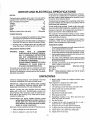
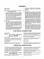
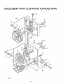
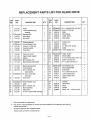
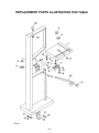
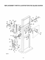
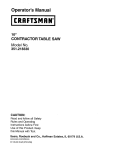
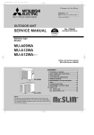
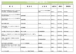
SAVE THIS MANUAL
FOR
FUTURE
REFERENCE
IS_EA/R8
OWNER'S
MANUAL
MODEL NO.
351.243951
8_A/,_,_/I: RI:1FTSM
I:1N
®
18" Band Saw
CAUTION:
Light Industrial Tool
READ ALL
INSTRUCTIONS
CAREFU
LLY!
Sold by SEARS, ROEBUCK
Part Noo 6666.03
o assembly
• operating
. repair parts
AND CO., Chicago,
IL 60684
U.S.A. ©
April 1993
FULL ONE-YEAR WARRANTY ON SEARS/CRAFTSMAN
18" Band Saw
If, within one full year from the date of purchase this Sears Craftsman 18" Band Saw fails due to a
defect in material or workmanship, Sears will repair it free of charge.
WARRANTY SERVICE 1S AVAILABLE BY SIMPLY RETURNING THE BAND SAW TO THE
NEAREST SEARS STORE OR SERVICE CENTER THROUGHOUT THE UNITED STATES.
This warranty gives you specific legal rights, and you may have other rights which vary from state
to state.
SEARS, ROEBUCK AND CO., D/817 WA, 3333 Beverly Road, Hofman Estates, IL 60179
GENERAL SAFETY INSTRUCTIONS
BEFORE ANY WORK IS DONE READ THE CAUTIONS LISTED BELOW CAREFULLY. WORKING
SAFELY PREVENTS ACCIDENTS.
e.,
Remove adjusting keys and wrenches. Form
habit of checking to see that keys and adjusting
wrenches are removed before turning on saw_
f
Keep all guards in place and in working order.
g, Keep all parts in working order. Check to determine that the guard or other parts will operate
properly and perform their intended function_
ho Check for damaged parts. Check for alignment of
moving parts, binding of moving parts, breakage of
parts, mounting and any other condition that may
affect a tool's operation.
i,
A guard or other part that is damaged should be
properly repaired or replaced. Do not perform
makeshift repairs., (Use the parts list provided with
owner's manual to order replacement parts,,)
OPERATOR SHOULD KNOW HOW TO USE SAW:
OPERATOR SHOULD BE PREPARED FOR JOB:
a.
b
c.
d,
e
f.
Wear proper apparel. Do not wear loose clothing,
gloves, neckties, rings, bracelets or other jewelry
which may get caught in moving parts of the saw,
Wear protective hair covering to contain long hair
Wear safety shoes with non-slip sole&
Wear safety glasses. Everyday glasses have only
impact resistant lenses. They are not safety glasses°
Wear face mask or dust mask if ct_ing operation
is dusty°
Be alert and think clearly. Never operate power
tools when tired, intoxicated
or when taking
medications that cause drowsiness,,
a
WORK AREA SHOULD BE READY FOR JOB:
a
Keep work area clean. Cluttered work areas and
workbenches invite accidents,
b,
b
Do not use power tools in dangerous environments. Do not use power tools in damp or wet
location& Do not expose power tools to rain.
Work area should be properly lighted,
c,
The proper electrical outlet should beavailabIefor
the logic A three-prong plug should be plugged
directly into a properly grounded, three-prong
receptacle.
Extension cords should have a grounding prong
and the three wires of the extension cord should be
the correct gauge,
Keep visitors a safe distance from work area.
e,
c
d.
e
f
g.
d
f
g
Keep children out of workplace° Make workshop
childproof,, Use padlocks, master switches and
remove starter keys to prevent any unintentional
use of power tools
h
SAW SHOULD BE MAINTAINED:
a,
Always unplug band saw prior to inspection,
b
Consult the owner's manual for specific maintaining and adjusting procedures
Keep band saw lubricated.,
Use sharp blades and keep the saw clean for safest
operation.
c
d
FOR POWER TOOLS
i,
j.
k
I,
-2-
Use the right tool for the job, Do not force a tool
or attachment to do a job for which it was not
designed.
Disconnect
saw from power when changing
blade°
Avoid accidental start-up. Make surethat the saw
is in the "off" position before plugging in,
Do not force a tool It wilt work most efficiently at
the rate for which it was designed.
Use recommended
accessories,
Consult the
owner's manual for recommended accessories.
The use of improper accessories may cause risk of
injury to persons.
Handle the workpiece correctly,, Use push sticks
or push blocks when required Protect hands from
possible injury°
Turn the saw off if it jams. A blade jams when it
digs too deeply into the workpiece. (The motor
force keeps it stuck in the workplace.)
Never leave saw running unattended, Turn the
power off and do not leave saw until it comes to a
complete stop.
Do not overreach.
Keep proper footing and
balance.
Never stand on saw, Serious injury could occur if
saw istipped or if blade is unintentionally contacted
Keep hands away from moving parts and blade
Know your saw. Learn its operation, application
and specific limitations.
CONTENTS
Warranty .............................................
General Safety Instructions
for Power Tools ..................................
Safety Instructions for Sand Saw .................
Motor and Electrical Specifications .................
Unpacking .......................................
Assembly .............................................
Electrical Connections
..........................
Operating Instructions ...........................
Maintenance ...........................................
Recommended Accessories ........................
Troubleshooting
...............................
Parts Illustration and List for Motor' +...............
Parts Illustration and List for Switch ................
Parts Illustration for Blade Drive ...................
Parts List for Blade Drive ..............................
Parts Illustration for Table ..........................
Parts List for Table ..............................
Parts illustration for Blade Guides .................
Parts List for Blade Guides ......................
2
2
3
4
4
5
5
5 -9
9
WARNING
9
10
12
13
14
15
16
17
18
19
LABEL
This warning label is placed in a specific location so it is
The 18" band saw has been marked with a warning label
visible to the operator when starting and operating the
that needs to be observed for' safe operation, The
saw,,
operator should be aware of the location and contents
of this label.
WARNING
FOR YOUR OWN SAFETY
[]
Read and understand owner's manual before
[]
_
m
]
operating band saw
_ways wear eye protection
Do not wear gloves, neckties, jewelry or loose
clothing,
Mount saw securely to floor,
Maintain proper adjustment of blade tension,
[]
i
Handle workpiece correctly Hold workpiece
against table, Use push sticks or push blocks
m when required
Guards should be in place and used at all times
[] Keep fingers out of path of blade
[] Turn machine off if it jams. Do not remove
jammed or cutoff pieces until the saw is turned
off, unplugged and the blade has stopped
]blade
guides and thrust bearings
Adjust upper guide to just clear workpfeoe,
SAFETY INSTRUCTIONS
9, AVOID SHOCKING THE BLADE+ Do not start a cut
on a sharp comer',, (See "Blade Pitch." page 7+)
I0+ KEEP BAND SAW MAINTAINED, Follow "Maintenance" instructions (page 9)
11+ DISCONNECT POWER Turn switch off and disconnect the powerwhenever band saw is not in use
Think safetyl Safety is a combination of operator
common sense and alertness at all times when the
band saw is being used.
WARNING:
DO NOT ATTEMPT TO OPERATE THE
BAND SAW UNTIL IT IS COMPLETELY
ASSEMBLED ACCORDING TO THE INSTRUCTIONS.
Caution;
1,+ KNOW GENERAL POWER TOOL SAFETY, Make
sure all precautions are understood and provided
for (page 2)+
Be certain to follow proper operating procedures despite familiarity gained from frequent use of your band saw+ Always
remember that being careless for even a
fraction of a second is sufficient time to
inflict severe injury.
The operation of any power tool can result in foreign
objects being thrown into the eyes. which can result in
severe eye damage,
Always wear safety goggles complying with ANSI Z87+1
(shown on package) before commencing saw operation+ Safety goggles are available at Sears retail or
catalog stores
2. SECURE ALL FASTENERS. Frequently check that
nuts and bolts are tight and have not vibrated loose
3,. FOLLOW OPERATING INSTRUCTIONS, Operate
the band saw as described in the manual,
4+ BE SURE MOTOR RUNS CLOCKWISE facing
shaft end+Blade must travel down toward the table+
5, USE THE CORRECT SPEED. The proper speed
will produce the optimum cut
6,. DO NOT FORCE THE CUT+ Slowing or stalling the
motor will overheat it+
7, DO NOT OVERHEAT THE WORKPIECE Excess
heat at the cut can damage the blade and reduce
the quality of the cut
8
FOR 18" BAND SAW
AVOID DEFLECTING THE BLADE, Adjust the
blade guides to hold the blade properly, (See
"Upper and Lower Blade Guides," pages 6 and 7)
-3-
MOTOR
AND ELECTRICAL
Do not remove or alter grounding prong in any manner_
In the event of a malfunction or breakdown, grounding
provides a path of least resistance for electrical current
to reduce risk of electrical shock.
MOTOR
The band saw is supplied with a motor° The 120 volt AC
capacitor start motor has the following specifications:
Max° Developed Horsepower
.......................
2
Voltage ..........................................
120
Amperes
Hertz
60
Phase
Single
RPM ...............................................
1725
Rotation (viewed from shaft end) ...........
Clockwise
The plug must be plugged into a matching outlet that is
properly installed and grounded in accordance'with all
local codes and ordinances_
7
....................................
Do not modify plug provided. If itwitl not fit in the outlet,
have the proper outlet installed by a qualified electrician°
Improper connection of the equipment-grounding conductor can result in a risk of electrical shock.
........................................
...........
..........................................
SPECIFICATIONS
The conductor with insulation having an outer surface
which is green or yellow with green stripe is the equipment-grounding conductor,,
POWER SOURCE
1_ The motor is designed for operation on the voltage
and frequency specified on motor nameplate_
If repair or replacement of the electrical cord or plug is
necessary, make sure the equipment-grounding
conductor is not connected to a line terminal,
2. Normal loads will be handled safely on voltages not
more than 10% above or below nameplate voltage
3. Running unit on voltages which are not within this
range may cause overheating and motor burnout.
GROUNDING
iNSTRUCTIONS
WARNING:
CHECK
WITH
A
QUALIFIED
ELECTRICIAN OR SERVICE PERSONNEL IF GROUNDING INSTRUCTIONS
ARE NOT UNDERSTOOD OR IF IN
DOUBT AS TO WHETHER BAND SAW
IS PROPERLY GROUNDED.
DO NOT PERMIT FINGERS TO TOUCH
TERMINALS
OF PLUGS WHEN INSTALLING OR REMOVING PLUG,
EXTENSION CORDS
I. The use of any extension cord wilt cause some drop
in the voltage and loss of power,
2. Wires of the extension cord must be sufficient in size
to carry the current and maintain adequate voltage.
3. Use the table below to determine the minimum wire
size (AWoG.) extension cord.
4_ Use only 3-wire extension cords having 3-prong
grounding type plugs and 3-pole receptacles which
accept the tool plug.
5, If power cord is worn, cut or damaged in any way,
have it replaced immediately.,
Extension Cord Length
Wire Size A.W.G,
Upto50 ft ...........................................
t6
50 - 100 ft ...........................................
14
NOTE:
Using extension cords over 100 ft. long is
not recommended.
The band saw is provided with a 3-conductor cord and
ground type plug which has a grounding prong approved by Underwriters Laboratories and the Canadian
Standards Association
UNPACKING
3. Motor pulley V-belts are shipped
cabinet door
Check for shipping damage_ tf any damage or loss has
occurred, immediately fife a claim with the carrier°
behind upper
Parts shipped in a separate box within crate:
IMPORTANT: TABLE AND RIP FENCE ARE COATED
WITH A PROTECTIVE COATING WHICH MUST BE
REMOVED FOR PROPER FIT AND OPERATION,
4.
5,
6,
7,
8
Remove coating with mild solvents such as mineral
spirits and a soft cloth, Nonflammable solvents are
recommended. After cleaning, cover all exposed surfaces with a light coating of oil, Paste ,wax is recommended for table tops
Rip fence and rip fence knob
120 Volt plug, 2 each wire nuts, and strain relief
2 Each band saw mounting brackets
Motor mount bracket
Standard and wide table inserts
9 Miter gauge assembly
10_ Handwheel, handle, 6-1,0 x 8ram set screw and
extra long 3mm hex wrench
11_ Hex pin for table
12, 4 Each 5/16-18 x 3/4", 8 each 5/16-18 x 1" and 1
each 5/16_18 x 1 1/8" hex head bolts
13, 20 Each 5/16" and 4 each 8mm flat washers
14 12 Each 5/16" and 4 each 8ram lock washers
Caution:Never
use highly volatile solvents, Avoid
getting cleaning solution on paint, rubber or
plastic parts as it may tend to deteriorate
these 1inishes, Use soap and water on paint,
plastic or rubber components.
Band saw comes assembled except for following parts:
1 Table is shipped in a box next to saw
15 4 Each 8mm-1.25 x 25ram hex head bolts
16, 9 Each 5/16"-18 hex nuts
2, Motor is shipped in a box next to saw
-4-
ASSEMBLY
5
MOUNT MOTOR
Refer to Figure 2
NOTE:
Do not mount motor pulley to motor until
motor is mounted to sawn
Refer to Figure 5._
Mount motor (Key No 1) to motor mount bracket
(Key No 2) using four each 5/16-18 x 1" he× head
bolts (Key NOr, 6), eight each flat washers (Key
No. 7) and four each lock washers (Key No, 8), Be
sure to mount motor to bracket using holes in
motor base as shown in Figure 2
2
Mount motor mount bracket to band saw base
using four each 8ram-1,25 x 25mm hex head bolts
(Key Noo 3), four each 8ram lock washers (Key
No 4) and four' each 8mm flat washers (Key No 5).
Refer to Figure 4
6
Mount table using four each 5/16-18 x 3/4" hex head
bolts (Key No 12), four each lock washers (Key
No, 13) and four eachflatwashers (KeyNo 14). Do
not tighten bolts Press the standard insert (Key
No. 2) into hole on top of table with beveled slot
aligned parallel with slot in table. Position table so
that blade is centered with insert slot and blade is
parallel with miter gauge slot Secure table by
tightening four each 5/16-18 x 3/4" hex head bolts
7
Thread 5/16"_18 hex nut (Key No. 16) onto 5/16-18
x I 1/8" hex head bolt (Key No,_15). Thread bolt into
threaded hole on bottom left side of table. Adjust
table perpendicular to blade using a square and
rotate 5/16-t8 x 1 1/8" bolt so that it holds table in
perpendicular position. Rotate hex nut against
table to secure bolt,
8
Mount two each mounting brackets (Key No.,24) to
holes on front side of band saw base using four
each 5/!64 8 × 1"hex head bolts (Key No, 25), eight
each flat washers (Key No. 14), four each lock
washers (Key No_ 13) and four each 5/16_'-18 hex
nuts (Key No 16). Secure mounting brackets to
floor using two each anchor bolts (not supplied).
!
3
4
Slide motor pulley (Key NQ 38) onto motor' shaft
with motor key in motor' shaft groove and motor
pulley groove° Align motor pulley with step pulley
(Key No_ 32) using a straight edge so that Vgrooves in motor pulley are aligned with V-grooves
in step pulley. Secure motor pulley with two set
screws (Key No. 40),
Slide belt tension handwheel (Key No..51) onto belt
tension shaft (Key No_ 52) and secure handwheel
with setscrew (Key No. 55) using 3mm hexwrench
Thread handle (Key Nov 53) into handwheeL
ELECTRICAL
Mount motor V-belt (Key No, 38) on motor pulley
and step pulley. Tension V-belts by rotating tension
handwheel
CON NECTIONS
Mount strain relief to motor connection box by removing
a "knock-out" on connection box and locking the strain
relief through "knock-out" hole with strain relief nut
WIRING MOTOR
WARNING:
ALL
ELECTRICAL
CONNECTIONS
MUST
BE
PERFORMED
BY A
QUALIFIED ELECTRICIAN.
Refer to Figure 2
Pass motor cord through strain relief and secure cord
with screw and nut on strain relief.
The motor (Key No, 1) should be wired for 120 volts and
clockwise rotation as viewed from shaft end of motor
Wire motor with wire nuts provided Be sure to ground
motor with green grounding wire in motor cord
A schematic supplied with motor will describe proper
wiring procedures
INSTALL PLUG
Refer to Figure 3
Refer to Figure 3
Wire motor tine cord (Key No,. 6) to motor using strain
relief (Key No, 8) and two wire nuts (not shown),
OPERATING
Wire line cord to plug (Key No, 9) provided Be sure to
ground plug using green grounding wire in line cord
INSTRUCTIONS
The 18" Band Saw isa versatile cutting tool and provides
four different cutting speeds so the saw can be used to
cut a variety of materials. The band saw offers convenient tensioning and tracking so changing blades is
not cumbersome
The band saw can accommodate
blade widths up to 1" for many types of cuts
Check to make sure blade is tensioned correctly_ Be
sure blade is tracking correctly Align table to blade
WARNING:
Support workpiece properly Use a smooth steady feed
to guide work through cut
Choose the proper speed for cutting operation
After turning on saw. allow blade to come to full speed
before attempting any cutting operation
ALWAYS OBSERVE THE FOLLOWING
SAFETY PRECAUTIONS.
Keep hands away and out of line with moving parts
Use proper blade for workpiece. Make sure blade
guides are positioned and adjusted correctly
Always wear eye protection
-5-
OPERATING
iNSTRUCTiONS
If blade tends to ride out of the cabinet, turn knob
clockwise to tilt idler wheel up.
If blade tends to ride into the cabinet, turn tracking knob
counterclockwise to tilt idler wheel down,
REMOVING BLADE
Refer to Figure 4,.
The 18" Band Saw is designed for convenient blade
changing. The table is provided with a slot which allows
the blade to be removed without disturbing the table.
Remove the stud so it will not obstruct removal of blade.
When blade is tracking properly, lock the position by
holding the knob and tightening the lever (Key No,, 17)
against the cabinet.
Loosen lever (Key Noo 17) which locks tracking knob
(Key No. t6).
ALIGNMENT
Alignment of drive wheel can be adjusted with hex bolts
(Key No, 27),
Lock position with nuts (Key No. 28).
INSTALLING BLADE
NOTE:
To replace the blade, the table stud must be removed as
described in "Removing Blade" above.
Although many of the adjustments may not be altered
when the blade is removed, every adjustment should be
checked prior to using a newly installed blade,
Only attempt adjusting drive wheel alignment if blade cannot be properly tracked
with tracking adjustment alone.
BLADE GUIDES
Refer to Figure &
Follow safety precautions which should be observed
every time the band saw is turned on,
Make sure the blade teeth are pointing in the correct
direction. Blade teeth must point down° Turn blade inside out if necessaryH
Center the blade on the blade wheel. Tension and track
the blade as described in the following sections.
Blade guides support the band saw blade at sides and
the rear of blade. The blade guides should be adjusted
to prevent twisting and deflection of blade,
Blade guides should not touch blade when no material
or workpiece is in contact with the blade,. Guides need
to be adjusted as described below,,
UPPER BLADE GUIDES
Do not use a new blade to complete a
previously started cut,
TENSIONING
OF DRIVE WHEEL
Refer to Figure 4.
A blade under high tension may also pull drive wheel out
of alignment.
Loosen blade tension by rotating handwheel (Key
No. 15)o
When removing blade be careful because blade may
spring from saw when tension is released. The released
blade can be removed and replaced with another blade,,
NOTE:
(Continued)
Refer to Figure 6
The upper blade guides employ two ball bearing sets on
adjusting pins for side support and a thrust bearing on
an adjusting pin at the rear.
BLADE
Refer to Figure 4.
Tension blade by turning the handwheel (Key No. 15).
Be sure blade guides are not interfering with the path of
the blade.
The guide depth bracket (Key No. 26) should be positioned so bearing on either side of blade will support as
much of blade width as possible without interfering with
the tooth set.,
Tighten blade until it is properly tensioned, A properly
tensioned blade will ring slightly when back of blade is
plucked, (Like a string on an instrument ,)
Adjust guide depth bracket by loosening bolt (Key No,
11) and sliding bracket into position.
NOTE:
Secure position of upper guide casting by tightening
bolt, Adjust guide bearings to the side of the blade with
a hex wrench.
CHECK THE TENSION OF A NEW BLADE.
ADDITIONAL
TENSION
MAY BE REQUIRED AFTER A FEW MINUTES OF
OPERATION.
Use a feeler gauge to check that the bearing is about
0°002" away from the blade
Lock the adjustment by tightening the bolt and nut (Key
Nos,, 34 and 13).
TRACKING BLADE
Refer To Figure 6.
Track the blade after it has been tensioned°
Loosen handle (Key No. 23) and push adjusting pin to
set thrust bearings 04002" away from back of the blade,
Proper tracking is achieved when drive wheel and idler
wheels are aligned,
Secure the position of the rear bearing by tightening
handle,
The knob (Key No, 16) is used to tilt tracking bracket
(Key No. 6) and align blade wheels,
A change in tension of blade will affect wheel alignment
Adjust height of the upper guide bearings to clear the
workpiece by 1/4"
Loosen knob (Key No, !) and reposition rack within
guides,
Turn idler wheel (Key No 4) by hand and observe how
blade rides on the wheels
Tighten knob to secure position on height adjustment
-6-
OPERATING
INSTRUCTIONS
LOWER BLADE GUIDES
Refer'to Figure 6.
The lower blade guide employs two guide blocks for side
to side support.
The lower guide bracket is spaced close to table surface
to minimize unsupported length of blade
Loosen nut (Key No, 27) to position the lower guide
bracket on the alignment block (Key No. 33).
Adjust the lower' guide bracket so the block does not
interfere with the blade set.
Loosen set screws for' guide blocks and adjust blocks to
about 0,002" from each side of blade_
Adjust bearing (Key No. 19) at rear' of blade by loosening
the knob (Key NOo32)_
ALIGN TABLE
To perform any straight cut accurately, table must be
aligned to the blade.
Once blade is tensioned and tracked correctly, the tabte
can be adjusted to it
Lock table in horizontal position_ Attach rip fence to the
table and push it against the blade,
Make sure rip fence and blade are parallel,
If table is not aligned, loosen four hex nuts which attach
table to upper trunnion and reposition the table_
Secure table position with four' hex bolts when it is
aligned. (Review "Assembly," Number 6,)
BLADE SELECTION
Blades vary depending on type of material to be cut, size
of the workpiece and type of cut that is being performed.
Characteristics which make blades different are width,
thickness, type of tooth and blade pitch
The width of blade describes the distance from tip of a
tooth to back of blade
Width of blade will affect rigidity of blade. A wider' blade
will wander' less and produce a straighter cut
Width of blade also limits the smallest radius which can
be cut,. A 1/4" wide blade can cut about a 1" diameter_
Blade thickness describes distance between sides of
blade, A thicker blade has more rigidity and stronger
teetb_
The narrow thick blade would be used to cut curves in
metal, while a wide thin blade would be used to re-saw
lumber
Blade manufacturers should be able to supply information about biades for specific applications
(Continued)
A blade cuts the work by removing material
The blade must scrape a chip of the workpiece away
from the cut,
The shape of gullet between teeth determines how much
material can be taken out with each blade tooth
Rake angle is the angle which the cutting face of the
tooth makes with a line perpendicular to the back of
blade°
A 0° rake angle is used to scrape harder materiats away
from the cut.
A positive rake angle causes the blade to dig aggressively into the workpiece,
Softer materials require more aggressive chip removal,
Larger gullets provide for faster removaf but have to be
limited in size because they make the blade teeth
weaker.
Blade teeth will also vary in the way which the teeth have
been set from one side to the other.
A wider set is used for contour work because the wider
kerf allows the operator to cut tighter curves,
BLADE PITCH
Pitch describes number of teeth per inch or tooth size.
Blades with more teeth per inch will produce smoother
cuts_
The type of material being cut determines number of
teeth which should be in contact with wor k, There should
always be at least three teeth in contact with the cut to
avoid shocking the blade.
Blade shocking occurs when the pitch is too large and
the blade tooth encounters too much material. This can
strip teeth from the blade.
When the pitch is too small the gullets of the teeth will fill
up, leading to the creation of excess heat for the blade.
In soft materials the proper blade has between 6 and 12
teeth per inch.
In cutting hard materials, where shocking is more
detrimental, there should be between 12 and 24 teeth
per'inch.
BLADE SPEED
The amount of force that the blade cuts with is deter_
mined by blade speed.
High cutting speeds are used on soft materials where
less force is needed and a high rate of material removal
is desired_
Low cutting speeds are used on hard materials where
more force is required,
To change the blade speed, position the V-belts in the
proper configuration as indicated (see Figure 1).
Reposition the V-belts and tension them as described in
the next section
TYPE OF TOOTH
The shape of teeth are varied to achieve specific cutting
results_
_7-
OPERATING
iNSTRUCTIONS
BLADE SPEED (FPM)
0
700
(Continued)
Rip fence is used to guide workpiece to prod uce straight
cuts on longer pieces_
Miter gauge is used to produce angle cUtSr
1480
Contour cutting is done by guiding workpiece
handed to produce curved shapes,
380_
free*
Beveled cutting can be done with any proper work guide
method by tilting the table°
Regard less ofwhich method of guiding the work is used,
a workpiece which overhangs the table by more than 10"
should be supported by freestanding material stands
RIP FENCE OPERATION
Refer to Figure 5_
Rip fence can be used to guide workpiece with one
square edge past blade when tabte is aligned properly,
Set the rip fence to the desired width of cut on the inside
of the throat, Do not forget about the saw kerf. Use a
square to measure from tip of a tooth to fence,, Lock
fence securely with knob (Key No. 14).
The portion of material between blade and fence is
considered the workpiece. Material on outside and behind the cut is scrap material which is being cut off,
Use right hand to keep work against fence,, Do not push
on scrap portion of work, This could pinch or bind blade
Avoid passing hands beyond the cut,, Use push sticks to
finish cuts and pass the workptece away from the blade.
©
Figure 1
FPM
MITER GAUGE OPERATION
270 - Steel, bronze
Use miter gauge for securing and holding workpiece at
desired angle to produce angled cuts, Use scale to
adjust gauge to desired angle,
Caution:
Never use miter gauge and rip fence at
the same time. Workpiece may bind
blade damaging workpiece and injuring operator.
700 - Brass, copper
1480 - Hard woods, plastic
3800 _ Soft woods, other light materials
REPOSITIONING
V-BELTS
Refer to Figures 1 and 4
CONTOUR SAWING
The band saw uses a two-belt drive system to provide a
selection of blade speeds (see Figure 1).,
When contour sawing, both hands must be used to keep
workpiece flat against the table and guided along
desired path,
Avoid positioning hands in line with blade, Hands could
contact blade if they slip,,
Idler pulley (Key No, 32, Figure 4) is fastened to tension
arm (Key No. 33) so both belts can be tensioned at the
same time.
Position tension arm by revolving handwheel (Key
No. 51). Loosen the V-belts by rotating the handwheel
counterclockwise
Try to stand to front of saw and use hands over portion
of table which is to the right of blade and before the cut
When the V-belts are loose, position them to desired
configuration (see "Blade Speed," and Figure 1) and
tighten by rotating the handwheel clockwise,
Do not attempt sharp corners which may twist or bind
the blade. Cut small corners by sawing around them,
Saw to remove smaller pieces of scrap until desired
shape is obtained,
Belts are properly tensioned when light pressure applied
between the pulleys produces about 1/2" deflection.
BEVEL CUTTING
Do not overtighten V-belts, Excessive tension on V-belts
will reduce available cutting force.
Refer to Figure 5,
Perform any saw operation at a bevel by tilting table
Loosen knob (Key No 8, Figure 5) to tilt table to desired
position, Use a square or protractor to set angle and lock
table in position with knob
Use caution when supporting work while bevel cutting
Do not allow work to hang on blade.
TYPE OF CUT
Band saw can be used to perform a variety of cuts
Cutting procedure used depends on size and desired
shape of cut
-8-
OPERATING
INSTRUCTIONS
(Continued)
The particles which collect on the drive wheel may affect
the band saw's operation.
DUST COLLECTION
Refer to Figure 4,
Sawdust or metal shavings wilt fail into the lower cabinet
of the saw.
The saw is fitted with a 4" male dust chute (Key No. 45)
for attachment to a dust collector°
Make sure that the brush (Key Noo 25) is in contact with
the wheel to properly remove foreign particles from the
drive wheel
Caution:
Use a dust collector with a 4" diameter hose to create
the proper' suction to remove debris from inside the
lower cabinet.
Check that the lower cabinet is free of
sawdust before performing any metal cutting operations. This is a possible fire
hazard,
MAINTENANCE
CLEANING
LUBRICATION
Keep machine and workshop c_ean,
The shielded ball bearings are permanently lubricated
when manufactured and require no further' lubrication
Do not allow sawdust or metal shavings to accumulate
on the band saw.
Small amounts of machine oil can be applied to
mechanism's threaded or' sliding surfaces.
Keep wheels clean,
Occasionally apply a coat of automobile type wax to the
table to keep it slick and corrosion free,,
Debris on wheels wJJ! cause poor" tracking and blade
slippage.
Keep mechanism's
foreign particles,
threaded or sliding surfaces free of
Operate the band saw with a dust collector to minimize
clean up.
RECOMMENDED
REPLACEMENT
,
,
KEEP BAND SAW IN REPAIR
If the power cord is worn or cut in any way, have it
replaced,
Replace V-belts and blade when they are worn°
Replace any damaged or missing part
Use the parts list to order'parts.
ACCESSORIES
(Catalog
Items)
BLADES
FOR
L x W"
INCH
TEETH
PER INCH
CATALOG
NUMBER
Wood
133 x 3/4
4
926656
Metal
133 x 3/4
10
926657
Metal
133 x 3/4
14
,926658
,,,,,,,,
-9-
TROUBLESHOOTING
SYMPTOM
CORRECTIVE
Excessive blade
breakage
Material not secure on table
2o Incorrect speed or feed
1o Squarely place work on table
2 Check Machinist Handbook for recommended
speed or feed
3 Check Machinist Handbook for recommended
blade type
4. Adjust blade propedy
5. Place blade in contact with work after saw has
reached full speed
6 Adjust wheel alignment propedy
7 Adjust blade guides propedy
8 Use thinner blade
9, Replace blade
Blade too coarse for material
Incorrect blade tension
5, Teeth in contact with work before saw
is started
6r,
Blade rubs on wheel flange
7.
Mis-aligned guides
8 Blade too thick for wheel diameter
9. Cracking at weld
4,_
, ,,,,,Hi, ,,,HU
I I ,I,ll,,,I
1,
2.
3_
4
Use finer tooth blade
Try next lower speed
Gently increase pressure
Reduce speed, increase rate of feed (scale)
Change blades (hard spots)
5
Increase rate of feed
6. Remove blade, twist inside out and
reinstall blade
7_ Increase tension to proper level
1o Blade too coarse
2.,
Too much speed
3o Inadequate feed pressure
4, Hard spots or scale in or on material
Premature blade
dulling
5 Work hardening of material
6 Blade installed backwards
7, Insufficient blade tension
,H,
i,i ill, ,i ,i,l,l,i
Crooked cuts
i i,
,i,l,l,ll,
Blade is twisting
Unusual wear on
side/back of blade
Teeth ripping from
blade
ii
,
,ill
1
2.
3.
4, Inadequate blade tension
5 Upper blade guide too far from
workpiece
6 Dull blade
7. Speed incorrect
4
5
9.,
8o Blade guide assembly toose
Blade thrust bearing not adjusted
properly
8
9.
1 Too much speed or feed
2, Blade too coarse
1. Reduce speed or feed
2_ Replace with finer blade
6,
7,
,
Hi
Use rip fence; adjust tilt of table at 90° to blade
Reduce rate of feed
Move both guide blocks within 0.002" to
blade (use gauge)
Increase blade tension properly
Adjust upper guide to clear workpiece
by 1/4"
Replace blade
Check Machinist Handbook for
recommended speeds
Tighten blade guide assembly
Move blade thrust bearing within 0°002"
behind blade back
H,
1
1. Cut is binding blade
i
i, 'H'H"'HH""'H
Decrease feed pressure
H,,
1, Blade guide blocks or bearings worn
2_ Blade guide blocks or bearings not
adjusted properly
3, Blade guide blocks or bearing bracket
loose
1_ Reptace
2, Adjust as pet"Lower
3
Tighten properly
1,
2.
3.
4.
1.
2,
3
4.
Use blade with finer teeth
Decrease feed rate
Hold workpiece firmly
Use blade with coarser teeth
1
2.
3
Reduce tension on blade
Reduce tension on drive belt
Use blade with finer teeth
4
Use blade with coarser teeth
5
Clean thoroughly; vacuum motor and belt area
Teeth too coarse for work
Feed too heavy
Vibrating workpiece
Teeth filling with material
i
Motor running
too hot
i
Work not square
2_ Rate of feed too great
3. Guide blocks not adjusted properly
l,,i, =
Rough cuts
ACTION(S)
,H,,, H
Blade Guides," page 7
,,i,ll
1. Blade tension too great
2, Drive bett tension too great
3 Blade too coarse for work
(typical when cutting pipe)
4, Blade too fine for work (typical when
cutting either thick or soft material)
5 Excessive dirt and sawdust
-10-
SERVICE RECORD
DATE
MAINTENANCE
PERFORMED
COMPONENTS
ll,_
i ,Ji,,IL,J,,,,,,,,,,,L
H ,ll,,,,,,,,ll
REQUIRED
ii
ill
,,
REPLACEMENT
PARTS ILLUSTRATION
FOR MOTOR
1
2
Figure 2 - Motor Illustration
REPLACEMENT
KEY
NO.
PART
NO,
1
2
6501o00
3
0302°00
4
1333..00
0695.00
STD523110
STD551031
5
6
7
8
9
*
5596o01
PARTS LIST FOR MOTOR
DESCRIPTION
Motor with key
Motor mount bracket
QTY.
t
1
8-! 25 x 25mm Bolt, hex head
8mm Washer, lock
4
8mm Washer, flat
* 5/16-18 x 1" Bolt, hex head
4
4
4
* 5/16" Washer, flat
8
STD551131
* 5/16" Washer, lock
4
STD541031
* 5/16"-18 Nut, hex
4
Standard hardware item available locally.
Always order by Part No. not by Key No
-12_
REPLACEMENT
PARTS ILLUSTRATION
FOR SWITCH
11
.1
Figure 3 - Switch illustration
REPLACEMENT
KEY
NO.
PART
NO,
i,,,
PARTS LIST FOR SWITCH
DESCRIPTION
,,,,
Switch with key
1
Switch plate
4-.70 x 10ram Screw, fiat head
* 6mm-1o0 Nut, hex
6-1.0 x 16ram Screw, flat head
t
4
2
2
5427.00
Line cord (switch to motor)
1
7
8
5428.00
7256.00
Line cord (power to switch)
Strain relief
1
2
9
10
5597.00
2820,00
Plug
6ram Washer, serrated
t
3
11
12
544200
0582.00
Strain relief
Strain relief
t
1
•
1
0423,00
2
3
4
5
542&00
5167,00
STD840610
5441.00
6
QTY.
"
Standard hardware item available locally
Always order by Part No, not by Key No,
q3-
REPLACEMENT
PARTS ILLUSTRATION
FOR BLADE DRIVE
16
2O
14
t4
17
23
22
18
26
2t
3O
22
37
53
35
51
44
32
5O
Figure 4
-t4-
REPLACEMENT
KEY
NO.
KEY]
PART
NO.
1
5101.00
2
0341.00
PARTS LIST FOR BLADE DRIVE
QTY.
DESCRIP1
Tread
17mm Retatnln_ ring,
extema!
2
4
2
1
1
3
4
5
STD315235
5103.00
510&00
* Bearing 6203
Idler wheel
Idler shaft
6
7
8
9
t0
510&00
STD852016
5107_00
5108o00
5109.00
Tracking brack,
* 16 mm Washer lock
1
16mm x 1_5Nu:, hex
Tension bracke
Pivot shaft
2
11
1305o00
Push nut, 10mr
12
5t1!.00
13
5112,00
14
15
STD85t008
511&00
Upper wheel s[ pport
Spacer
8ram Washer, flat
Blade tension handwheel
2
1
1
5
1
NO.I
27
28
29
30
31
32
PART
NO.
I STD833020
! STD840610
I 5t23.00
I 5t24_00
l 5125,00
j 512600
DESCRIPTION
QTY,
* 6-1.0 x 20mm Bolt, hex head
* 6mm-l.0 Nut, hex
Shaft
Drive Wheel
V-Belt, 3L610
Idler pulley
q
t
1
1
33
34
35
36
37
] 5127,,00
1 512&00
1 5!29,00
1 2809.00
I STD851016
39
40
41
STD3O3340 * V-Belt, 3L340
1 2796.00
Motor pulley
6-1.0 x 12mm Screw, set fL pt
I 281&00
I 519600
20mm-1.5, Nut, hex
* 6-1o0 x 8ram Screw, set
I 104300
42
Tension arm
Clevis
8 x 16ram Pin, spring
Collar
* 16ram Washer, flat
1
J
16
17
18
5114o00
511500
2807.00
19
STD835016
20
7257.00
21
22
23
124
J25
!26
STD852020
5440.00
STD840812
5120.00
512t_00
5!22.00
1
1
Blade tracking knob
Tracking lever
8mm-1o25 Nut, hex
head washe
* 8qo25 x 16mm
,
hex head
Door knob
5
4
2
* 20mm Washer, lock
Latch
* 8mmq.25
Nut, hex
Brush bushing
Chip brush
8-1.25 x 100ran
, carriage
1
2
2
1
1
1
43 't STD851008
44 t 3837°00
45 I 5!38.00
46 t 280000
47 t 5t40..01
48 1 5141.01
49 t 5t42.00
50t
51 I
52 I
53 ]
O
I
* 8mm Washer', fiat
Bearing 6203 RSR
Dust chute
4-0°7 x 6ram Screw, set
Lower cabinet door
Upper' cabinet door
Spacer
5598.00
736800
277&00
Cabinet
Handwheel
Shaft
Handle
£ 26656
Blade, 133"-4 hook (wood)
t
4
!
1
1
1
4
I
i
i
1
1
1
1
I
t
I
i
1
Not economical
for reptacemenL
e
Not shown. The accessories are current and were available in the catalog at the time this
manual was printed.
*
Standard hardware item, available locally
Always order by Part No not by Key No
-15-
REPLACEMENT
PARTS ILLUSTRATION
d
2
_3
18
14
/
24
Figure 5
--16 i
FOR TABLE
REPLACEMENT
......KEY
NO.
1
2
3
4
PARTS LIST FOR TABLE
PART
NO.
535900
517&00
5195.00
5185.01
DESCRIPTION ................
Table
Table insert, thin slot
Table insert, wide slot
Upper trunnion
QTY.
1
1
1
1
5
6
7
8
5187+01
5184.00
5! 8600
STD851008
Lower' trunnion
8-1.25 x 50ram Bolt, carriage
Guide block
* 8mm Washer, fiat
1
t
t
1
9
10
11
12
5210+00
5188,00
2807.00
STD523107
Lock knob
8-1+25x 20mm Bolt, carriage
8mm-1.25 Nut, hex hdL washer
* 5/16-18 x 3/4" Bolt, hex head
1
4
4
4
13
14
15
16
STD551131
STD551031
6542.00
STD541031
r* 5/16" Washer, lock
* 5/16" Washer, flat
5/16-18 x 1 1/8" Bolt, hex head
E* 5/16"-18 Nut, hex
17
18
19
2O
0211 +00
7634.+00
7635+00
5351.00
21
22
23
24
25
0003+00
5356+00
5358+00
5354.00
STD523110
6666.03
, ,, .,,,,,,,,,,,v,,
, ,,,
o
,,
8
12
t
5
,, ,,_,,,,,u,,,,,
1
1
1
1
Table stud
Scale
Screw, thread forming
Rip fence
Knob, external threads
Eye bolt
12mm-1o75 Nut, hex nylon
Mountinq bracket
* 5/16q8 x 1" Bolt, hex head
Owner's Manual
1
1
1
2
4
1
Standard hardware item available locally
Not shown
Always order by Part No not by Key No
REPLACEMENT
PARTS LIST FOR MITER GAUGE
KEY
NO.
1
2
3
4
PART
NO.
8251+00
8250.00
1370.00
STD551025
Miter gauge
Miter gauge bar
#10 Fiber washer
* 1/4" Washer, flat
5
6
7
8
9
10
11
12
13
14
15
16
17
825500
8252+00
STD541010
STD511007
8253.00
8254.00
388800
STD511002
599100
1833.00
109300
825600
825700
Threaded pin
Knob
* #10-24 Hex nut
* #10-24 x 3/4" Screw, pan head
indicator
Scale
#10 Washer, fiat
* #10-24 x 1/4" Screw, pan head
#10-24 x 1/2" Screw, flat head
5-80 x 8mm Screw, fiat head
Guide
Indexing pin
Miter gauge assembly
*
e
Figure 5a
DESCRIPTION
Standard hardware item available locally
Not shown
Always order by Part No not by Key No
-17-
QTY.
1
1
1
1
1
1
3
3
1
1
1
!
2
1
1
1
1
REPLACEMENT
PARTS ILLUSTRATION
FOR BLADE GUIDES
• 27
28
11
32
34
22
13
14
Figure 6
-18-
REPLACEMENT PARTS LIST FOR
BLADE GUIDES
KEY
NO,
PART
NO.
DESCRIPTION
QTY
,
,,,, ,,,,
1
2
3
4
5
521&00
7258.00
0832,00
7260700
2810.00
Lock knob
10ram Washer
8mmq.25 Nut, hex
Blade guide handwheel
Pinion gear ...........
1
4
1
t
1
6
7
8
9
10
5! 48.00
5211.00
5212o00
5151,.00
5152.00
8mm Retaining ring, external
Bolt plate
Guide extrusion
Guide bracket
Pinion bracket
1
1
1
2
1
1t
12
13
14
15
STD833025
5213.00
STD840610
STD833012
5154.00
* 6-140 x 25mm Bolt, hex head
5mm x 16 Screw, thread forming
* 6-1.0mm Nut, hex
* 6-1.0 x 12mm Bolt, hex head
6-1.0 × 20mm Screw, flat head
16
17
18
19
2O
STD851006
5155°00
3646°00
STD315465
2818.00
* 6mm Washer', flat
Upper guide casting
Guide bearing pin
* Guide bearing (626Z)
6mm-l,0 Nut, hex head washer
21
22
23
24
25
5159.00
516Q.00
5161_00
5162.00
7261.00
26
27
28
29
3O
5164,00
5153,00
STD851006
2819.00
5t66.00
Guide depth bracket
6-1,0mm Nut, hex nylon
* 6ram Washer, flat
6q.0 x 12ram Screw, flat po#lt set
Lower' guide casting
31
32
33
34
35
36
37
38
39
40
365&00
5169.00
5168.00
STD833020
STD851004
STD833016
STD840407
5156.00
7636.00
0781.00
Guide block
Thrust bearing lock knob
Alignment block
* 6-1,0 x 20mrn Bolt, hex head
* 4mm Washer, flat
* 6-1,0 x 15mm Bolt, hex head
* 4mm-.70 NUt, hex
4ram Washer, serrated
Blade guard clip
4-.70 x 8mm Screw, pan head
41
42
43
44
45
5215o00
5216o00
7637_00
5188°00
2811.00
4mm-o70 x 20 Screw, pan head
Rack
Blade Guard
8mm-1,25 x 20 Bolt, carriage
Pinion shaft
6
2
1
t
1
46
47
2817.00
7262.00
4 x 20ram Pin, spring
8mm Washer, flat
t
1
, ,,,,,,
2
2
2
2
1
,,,,,,,,,
Guide
Thrust
Clamp
Thrust
4
1
3
3
6
bearing clamp
bearing assembly
handle
bearing clamp
2
1
1
t
Guide attaching bracket
t
Always order by Part No. not by Key No.
-t9-
t
4
2
2
1
2
1
1
4
_,
6
2
2
1
6
18" Band Saw
Light Industrial Tool
OWNER'S
MANUAL
SERVICE
Thank you for purchasing your 18" Band Saw from Sears
This unit will provide you with many years of reIiable service
Should the need exist for repair parts or service, simply
contact any Sears Service Center and most Sears, Roebuck
and Co stores Be sure to provide ail pertinent facts when
you call or visit. The model number of your 18" Band Saw
will be found on the upper cabinet door
MODEL NO.
351.243951
HOW TO ORDER
REPAIR PARTS
All parts listed may be ordered from any Sears Service
Center and most Sears stores. If the parts you need are not
stocked locally, your order wilt be electronically transmitted
to the Sears Repair Parts Distribution Center for handling
When ordering
information:
repair
parts, always
give
the following
NAME OF ITEM: t8" Band Saw
MODEL NUMBER:
351 243951
PART NUMBER:
PART DESCRIPTION:
Sold by SEARS,
Part No. 6666.03
ROEBUCK
AND CO., Chicago,
IL 60684 UoS,A. ©
April
1993