1
Siemens Cellular Engines
TC35 Module
TC37 Module
TC35 Terminal
Version: 04.00
DocID: TC3X_ATC_01_V04.00
AT Command Set
Document Name:
AT Command Set
Siemens Cellular Engines
Version:
Date:
Doc Id:
Status:
04.00
May 29, 2002
TC3X_ATC_01_V04.00
Released
General note
With respect to any damages arising in connection with the described product or this document,
Siemens shall be liable according to the General Conditions on which the delivery of the described
product and this document are based.
This product is not intended for use in life support appliances, devices or systems where a malfunction
of the product can reasonably be expected to result in personal injury. Siemens AG customers using
or selling this product for use in such applications do so at their own risk and agree to fully indemnify
Siemens for any damages resulting from illegal use or resale.
Applications incorporating the described product must be designed to be in accordance with the
technical specifications provided in these guidelines. Failure to comply with any of the required
procedures can result in malfunctions or serious discrepancies in results.
Furthermore, all safety instructions regarding the use of mobile technical systems, including GSM
products, which also apply to cellular phones must be followed.
Handheld applications such as mobile phones or PDAs incorporating the described product must be in
accordance with the guidelines for human exposure to radio frequency energy. The Specific
Absorption Rate (SAR) of the application must be evaluated and approved to be compliant with
national and international safety standards or directives.
Subject to change without notice at any time.
Copyright
Copying of this document and giving it to others and the use or communication of the contents thereof,
are forbidden without express authority. Offenders are liable to the payment of damages. All rights
reserved in the event of grant of a patent or the registration of a utility model or design.
Copyright © Siemens AG 2001
TC3X_ATC_01_V04.00
Page 2 of 204
29.05.2002
AT Command Set
Contents
0
Version History .............................................................................................7
1
Introduction .................................................................................................10
1.1
1.2
1.3
1.4
1.4.1
1.4.2
1.4.3
1.5
1.6
1.6.1
1.6.2
Scope of the document ...........................................................................................................10
Supported product versions and related documents ..............................................................10
Conventions ............................................................................................................................11
AT command syntax ...............................................................................................................11
Using parameters....................................................................................................................11
Combining AT commands on the same command line ..........................................................12
Entering successive AT commands on separate lines ...........................................................12
Supported character sets ........................................................................................................13
Flow control .............................................................................................................................14
Software flow control (XON/OFF flow control) ........................................................................14
Hardware flow control (RTS/CTS flow control) .......................................................................14
2
Standard V.25ter AT Commands ...............................................................15
2.1
2.2
2.3
2.4
2.5
2.6
2.7
2.8
2.9
2.10
2.11
2.12
2.13
2.14
2.15
2.16
2.17
2.18
2.19
2.20
2.21
2.22
2.23
2.24
2.25
2.26
2.27
2.28
2.29
2.30
2.31
2.32
2.33
2.34
2.35
2.36
2.37
2.38
A/ Repeat previous command line .........................................................................................15
+++ Switch from data mode to command mode ....................................................................15
AT\Qn Flowcontrol .................................................................................................................16
ATA Answer a call..................................................................................................................16
ATD Mobile originated call to dial a number ..........................................................................17
ATD><mem><n> Originate call to phone number <n> in memory <mem> ..........................18
ATD><n> Originate call to phone number selected from active memory..............................20
ATD><str> Originate call to phone number in memory with corresponding field ..................21
ATDI Mobile originated call to dialable ISDN number <n> ....................................................22
ATDL Redial last telephone number used .............................................................................23
ATE Enable command echo ..................................................................................................24
ATH Disconnect existing connection .....................................................................................24
ATI Display product identification information........................................................................25
ATI[value] Display additional identification information..........................................................25
ATL Set monitor speaker loudness........................................................................................26
ATM Set monitor speaker mode ............................................................................................26
ATO Switch from command mode to data mode...................................................................26
ATQ Set result code presentation mode................................................................................27
ATP Select pulse dialling .......................................................................................................27
ATS0 Set number of rings before automatically answering the call ......................................27
ATS2 Escape code sequence................................................................................................28
ATS3 Write command line termination character ..................................................................28
ATS4 Set response formatting character...............................................................................28
ATS5 Write command line editing character..........................................................................29
ATS6 Set pause before blind dialling.....................................................................................29
ATS7 Set number of seconds to wait for connection completion ..........................................30
ATS8 Set number of seconds to wait for comma dial modifier ..............................................30
ATS10 Set disconnect delay after indicating the absence of data carrier .............................31
ATS18 Extended error report.................................................................................................31
ATT Select tone dialling .........................................................................................................31
ATV Set result code format mode..........................................................................................32
ATX Set CONNECT result code format and call monitoring..................................................32
ATZ Set all current parameters to user defined profile ..........................................................33
AT&C Set circuit Data Carrier Detect (DCD) function mode..................................................33
AT&D Set circuit Data Terminal Ready (DTR) function mode ...............................................34
AT&F Set all current parameters to manufacturer defaults ...................................................34
AT&S Set circuit Data Set Ready (DSR) function mode........................................................35
AT&V Display current configuration .......................................................................................36
TC3X_ATC_01_V04.00
Page 3 of 204
29.05.2002
AT Command Set
2.39
2.40
2.41
2.42
2.43
2.44
2.45
2.46
2.46.1
AT&W Store current configuration to user defined profile .....................................................37
AT+GCAP Request complete TA capabilities list ..................................................................38
AT+GMI Request manufacturer identification........................................................................38
AT+GMM Request TA model identification............................................................................38
AT+GMR Request TA revision identification of software status ............................................39
AT+GSN Request TA serial number identification(IMEI).......................................................39
AT+ILRR Set TE-TA local rate reporting ................................................................................40
AT+IPR Set fixed local rate.....................................................................................................41
Autobauding ............................................................................................................................42
3
AT Commands for FAX...............................................................................43
3.1
3.2
3.3
3.4
3.5
3.6
3.7
3.8
3.9
3.10
3.11
3.12
3.13
3.14
3.15
3.16
3.17
3.18
3.19
3.20
3.21
3.22
3.23
3.24
3.25
3.26
3.27
AT+FBADLIN Bad Line Threshold .........................................................................................43
AT+FBADMUL Error Threshold Multiplier..............................................................................44
AT+FBOR Query data bit order .............................................................................................44
AT+FCIG Query or set the Local polling id ............................................................................45
AT+FCLASS Fax: Select, read or test service class .............................................................45
AT+FCQ Copy Quality Checking ...........................................................................................46
AT+FCR Capability to receive................................................................................................46
AT+FDCC Query or set capabilities.......................................................................................47
AT+FDFFC Data Compression Format Conversion ..............................................................48
AT+FDIS Query or set session parameters...........................................................................49
AT+FDR Begin or continue phase C data reception..............................................................50
AT+FDT Data Transmission ..................................................................................................50
AT+FET End a page or document .........................................................................................51
AT+FK Kill operation, orderly FAX abort................................................................................51
AT+FLID Query or set the Local Id setting capabilities .........................................................51
AT+FMDL Identify Product Model..........................................................................................52
AT+FMFR Request Manufacturer Identification ....................................................................52
AT+FOPT Set bit order independently...................................................................................52
AT+FPHCTO DTE Phase C Response Timeout ...................................................................53
AT+FREV Identify Product Revision ......................................................................................53
AT+FRH Receive Data Using HDLC Framing .......................................................................53
AT+FRM Receive Data ..........................................................................................................54
AT+FRS Receive Silence ......................................................................................................54
AT+FTH Transmit Data Using HDLC Framing ......................................................................54
AT+FTM Transmit Data .........................................................................................................55
AT+FTS Stop Transmission and Wait ...................................................................................55
AT+FVRFC Vertical resolution format conversion .................................................................56
4
AT Commands originating from GSM 07.07 .............................................57
4.1
4.2
4.3
4.4
4.5
4.6
4.6.1
4.7
4.8
4.9
4.10
4.11
4.12
4.13
4.14
4.15
4.16
4.17
4.18
AT+CACM Accumulated call meter (ACM) reset or query ....................................................57
AT+CALA Set alarm time.......................................................................................................58
AT+CAMM Accumulated call meter maximum (ACMmax) set or query................................61
AT+CAOC Advice of Charge information ..............................................................................62
AT+CBST Select bearer service type ....................................................................................63
AT+CCFC Call forwarding number and conditions control....................................................64
Examples: Call forwarding ......................................................................................................65
AT+CCLK Real Time Clock ...................................................................................................67
AT+CEER Extended error report ...........................................................................................68
AT+CFUN Set phone functionality .........................................................................................69
AT+CGMI Request manufacturer identification ......................................................................71
AT+CGMM Request model identification...............................................................................71
AT+CGMR Request revision identification of software status ...............................................71
AT+CGSN Request product serial number identification (IMEI) identical to GSN ................72
AT+CHLD Call hold and multiparty .........................................................................................72
AT+CHUP Hang up call .........................................................................................................73
AT+CIMI Request international mobile subscriber identity....................................................73
AT+CLCC List current calls of ME .........................................................................................74
AT+CLCK Facility lock ...........................................................................................................75
TC3X_ATC_01_V04.00
Page 4 of 204
29.05.2002
AT Command Set
4.18.1
4.18.2
4.18.3
4.19
4.20
4.21
4.22
4.23
4.24
4.24.1
4.25
4.26
4.27
4.28
4.29
4.30
4.31
4.31.1
4.32
4.33
4.34
4.35
4.36
4.37
4.38
4.39
4.40
4.41
4.42
4.43
4.44
4.45
4.46
4.47
Examples: Enabling / disabling PIN 1 authentication .............................................................77
Examples: Phone lock.............................................................................................................77
Examples: Call barring ............................................................................................................79
AT+CLIP Calling line identification presentation....................................................................81
AT+CLIR Calling line identification restriction (by *# sequence) ...........................................82
AT+CLVL Loudspeaker volume level ....................................................................................83
AT+CMEE Report mobile equipment error ............................................................................84
AT+CMUT Mute control .........................................................................................................85
AT+CMUX Enter multiplex mode ...........................................................................................86
Restricted use of AT commands in Multiplex mode................................................................87
AT+COPN Read operator names ..........................................................................................89
AT+COPS Operator selection................................................................................................90
AT+CPAS Mobile equipment activity status ..........................................................................92
AT+CPBR Read current phonebook entries..........................................................................93
AT+CPBS Select phonebook memory storage......................................................................94
AT+CPBW Write phonebook entry ........................................................................................95
AT+CPIN Enter PIN ...............................................................................................................96
What to do if PIN or password authentication fails? ...............................................................99
AT+CPIN2 Enter PIN2 .........................................................................................................101
AT+CPUC Price per unit and currency table .......................................................................103
AT+CPWD Change password .............................................................................................104
AT+CR Service reporting control .........................................................................................106
AT+CRC Set Cellular Result Codes for incoming call indication.........................................107
AT+CREG Network registration ...........................................................................................108
AT+CRLP Select radio link protocol param. for orig. non-transparent data call..................110
AT+CRSM Restricted SIM access .......................................................................................111
AT+CSCS Set TE character set...........................................................................................112
AT+CSNS Single Numbering Scheme ................................................................................113
AT+CSQ Signal quality ........................................................................................................114
AT+CSSN Supplementary service notifications...................................................................115
AT+CUSD Unstructured supplementary service data .........................................................116
AT+VTD=<n> Tone duration................................................................................................117
AT+VTS DTMF and tone generation (<Tone> in {0-9, *, #, A, B, C, D}) .............................118
AT+WS46 Select wireless network .......................................................................................119
5
AT commands originating from GSM 07.05 for SMS .............................120
5.1
5.2
5.3
5.4
5.5
5.6
5.7
5.8
5.9
5.10
5.11
5.12
5.13
5.14
5.15
5.16
AT+CMGC Send an SMS command ...................................................................................120
AT+CMGD Delete SMS message........................................................................................121
AT+CMGF Select SMS message format .............................................................................121
AT+CMGL List SMS messages from preferred store ..........................................................122
AT+CMGR Read SMS message .........................................................................................125
AT+CMGS Send SMS message..........................................................................................128
AT+CMGW Write SMS message to memory.......................................................................130
AT+CMSS Send SMS message from storage.....................................................................132
AT+CNMA New SMS message acknowledge to ME/TE, only phase 2+ ............................133
AT+CNMI New SMS message indications ..........................................................................134
AT+CPMS Preferred SMS message storage ......................................................................137
AT+CSCA SMS service centre address ..............................................................................138
AT+CSCB Select cell broadcast messages.........................................................................139
AT+CSDH Show SMS text mode parameters .....................................................................140
AT+CSMP Set SMS text mode parameters.........................................................................141
AT+CSMS Select Message Service ....................................................................................142
6
Siemens defined AT commands for enhanced functions .....................143
6.1
6.2
6.3
6.4
6.5
AT+CXXCID Display card ID (identical to AT^SCID)...........................................................143
AT^MONI Monitor idle mode and dedicated mode ..............................................................144
AT^MONP Monitor neighbour cells......................................................................................146
AT^SACM Advice of charge and query of ACM and ACMmax ...........................................147
AT^SBC Battery charging / discharging and charge control................................................148
TC3X_ATC_01_V04.00
Page 5 of 204
29.05.2002
AT Command Set
6.6
6.7
6.8
6.9
6.10
6.11
6.12
6.13
6.14
6.15
6.16
6.17
6.18
6.19
6.20
6.21
6.22
6.23
6.24
6.25
6.26
6.27
6.28
6.29
6.30
6.31
6.32
6.33
6.34
6.35
6.36
6.37
6.38
6.39
6.40
AT^SCID Display SIM card identification number................................................................151
AT^SCKS Set SIM connection presentation mode and query SIM connection status ........152
AT^SCNI List Call Number Information ...............................................................................153
AT^SCTM Set critical operating temperature presentation mode or query temperature.....154
AT^SDLD Delete the “last number redial“ memory..............................................................156
AT^SHOM Display Homezone.............................................................................................156
AT^SLCD Display Last Call Duration...................................................................................156
AT^SLCK Facility lock ..........................................................................................................157
AT^SMGL List SMS messages from preferred storage.......................................................158
AT^SMGO Set or query SMS overflow presentation mode or query SMS overflow ...........159
AT^SMGR Read SMS message without set to REC READ ................................................160
AT^SMONC Cell Monitoring ................................................................................................161
AT^SMSO Switch off mobile station ....................................................................................162
AT^SM20 Set M20 Compatibility .........................................................................................162
AT^SNFD Set audio parameters to manufacturer default values........................................163
AT^SNFI Set microphone path parameters .........................................................................163
AT^SNFM Mute microphone................................................................................................164
Audio programming model ....................................................................................................164
AT^SNFO Set audio output (= loudspeaker path) parameter..............................................165
AT^SNFPT Call progress tones ..........................................................................................166
AT^SNFS Select audio hardware set...................................................................................167
AT^SNFV Set loudspeaker volume......................................................................................168
AT^SNFW Write audio setting in non-volatile store .............................................................168
AT^SPBC Search the first entry in the sorted telephone book ............................................169
AT^SPBG Read entry from active telephone book via sorted index ...................................170
AT^SPBS Steps the selected phonebook alphabetically.....................................................171
AT^SPIC Display PIN counter..............................................................................................172
AT^SPLM Read the PLMN list .............................................................................................173
AT^SPLR Read entry from the preferred operators list .......................................................174
AT^SPLW Write an entry to the preferred operators list......................................................175
AT^SPWD Change password for a lock ..............................................................................176
AT^SSCONF SMS Configuration........................................................................................177
AT^SSDA Set Display Availability.......................................................................................178
AT^SSYNC Configure SYNC Pin.........................................................................................179
AT^STCD Display Total Call Duration .................................................................................180
7
APPENDIX .................................................................................................181
7.1
7.1.1
7.1.2
7.1.3
7.1.4
7.1.5
7.1.6
7.1.7
7.1.8
7.1.9
7.1.10
7.1.11
Summary of ERRORS and Messages..................................................................................181
Summary of CME ERRORS related to GSM 07.07..............................................................181
Summary of CMS ERRORS related to GSM 07.05..............................................................183
Summary of Unsolicited Result Codes (URC) ......................................................................185
Result codes .........................................................................................................................187
Cause Location ID for the extended error report (AT+CEER) ..............................................187
GSM release cause for L3 Radio Resource (RR) (AT+CEER) ...........................................188
SIEMENS release cause for L3 Radio Resource (RR) (AT+CEER) ...................................188
GSM release cause for Mobility Management (MM) (AT+CEER) ........................................189
SIEMENS release cause for L3 Mobility Management (MM) (AT+CEER) ...........................189
GSM release cause for L3 Call Control (CC) (AT+CEER) ...................................................190
SIEMENS release cause for L3 Call Control (CC) and Mobile Station Manager (MSM)
(AT+CEER) ...........................................................................................................................191
SIEMENS release cause for L3 Advice of Charge (AOC) (AT+CEER) ...............................192
GSM Release cause for Supplementary Service call (AT+CEER).......................................192
SIEMENS release cause for Call-related Supplementary Services (CRSS) (AT+CEER)...193
Summary of PIN requiring AT Commands............................................................................194
AT commands available before entering the SIM PIN..........................................................196
Standard GSM service codes ...............................................................................................198
Additional notes on ^SCCFC, ^SCCWA, ^SCLCK ...............................................................200
GSM and UCS2 alphabet tables...........................................................................................202
7.1.12
7.1.13
7.1.14
7.2
7.3
7.4
7.4.1
7.5
TC3X_ATC_01_V04.00
Page 6 of 204
29.05.2002
AT Command Set
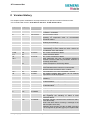
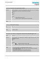
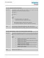
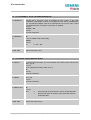
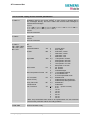
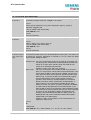
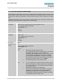
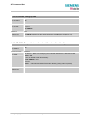
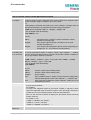
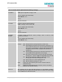
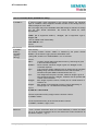
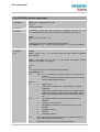
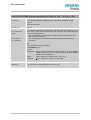
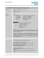
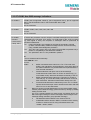
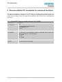
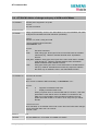
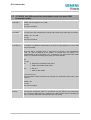
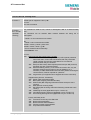
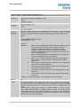
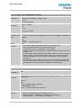
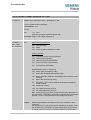
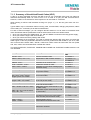
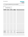
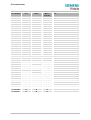
0 Version History
This chapter reports modifications and improvements over previous versions of the document.
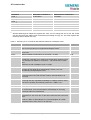
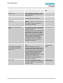
"AT Command Set" Version TC3x-ATC-01-V03.10=> TC3x5-ATC-01-04.00
Chapter
Page
AT command
What is new
1.5
13
Character sets
1.6
1.4.2
14
12
Flow control
Any command
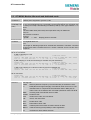
2.3
16
AT\Qn
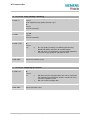
2.21
4.2
28
58f
ATS2
AT+CALA
4.6 and
4.6.1
4.18
4.18.3
64f
65
75
AT+CCFC
Chapter revised and associated character set tables
in Chapter 7.5 updated.
How to use flow control.
Maximum length of command line buffer added. Note
regarding on sequential order of concatenated
commands added.
Further details added: Using RTS/CTS handshake.
Restoring AT\Q settings.
Command description added.
Statement regarding the URC +CALA <text> revised:
If autobauding is active neither the URC +CALA nor
the individual <text> will appear.
New <class> parameters added.
Further examples added.
New <class> parameters added.
Under parameter “PS” lock, the following statement
has been removed: “ME may remember numbers of
previously used cards.”
Further examples for call barring added.
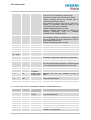
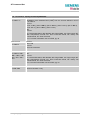
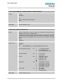
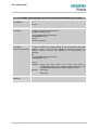
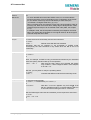
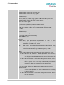
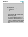
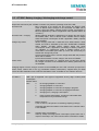
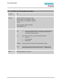
Fax specific AT commands are not usable.
AT\Q3 (hardware flow control) is recommended.
Minimum bit rate set with AT+IPR: 4.8 kbps
Timing algorithm of incorrect password corrected
Note added: Realistic BER values can be obtained
only if there is a call in progress.
Command syntax corrected: Parameter <speed> is
mandatory.
Further notes regarding the usage of AT+CLVL and
AT^SNFV added.
Further notes regarding the usage of AT+MUT and
AT^SNFM added.
Chapter revised.
Note regarding AT^SSCONF added.
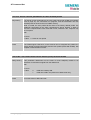
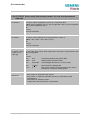
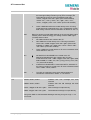
AT+CLCK
4.24.1
79
87
AT+CMUX
4.31.1
4.42
99
114
AT+CPIN
AT+CSQ
4.5
63
AT+CBST
4.21
83
AT+CLVL
4.23
85
AT+CMUT
4.39
5.4
5.2
5.10
111
122
121
134
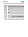
AT+CRSM
AT+CMGL
AT+CMGR
AT+CNMI
5.7
130
AT+CMGW
TC3X_ATC_01_V04.00
Note regarding AT^SSCONF added.
Note regarding the handling of Class 0 short
messages added.
Parameter <length> corrected (only required for PDU,
not for text mode).
Result code after failure of storing a message to the
SIM card (ME returns OK).
Statement about sending e-mails via SMS corrected:
If not recognized by provider, @ may be replaced with
“*”.
Page 7 of 204
29.05.2002
AT Command Set
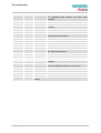
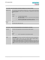
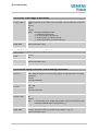
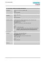
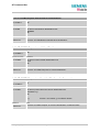
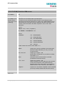
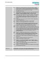
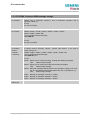
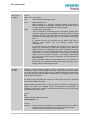
6.2
144ff
AT^MONI
6.3
146
At^MONP
6.7
6.13
6.17
6.25
6.20, 6.22,
6.24 – 6.28
6.37
152
157
161
166
163ff
AT^SCKS
AT^SLCK
AT^SMONC
AT^SNFPT
AT^SNF…
177
AT^SSCONF
6.38
7.1.2
178
183f
7.1.4
7.1.5
187
187
7.1.11
191
7.4
7.4.1
7.3
198
200
196
Examples on page 144 updated.
<chann> and <rs> explained in greater detail
References for 3GPP TS 05.05 and 05.08 added
Frequency hopping will now be indicated with “h”
(instead of the previously used “0”.
Notes modified: If during a connection the radio cell is
changed, the parameters PWR and RXLev of the
‘Serving Cell’ part will not be updated.
Statement regarding RING line revised.
Statement regarding different values of identical cell
monitoring
parameters
(used
for
AT^MONI,
AT^MONP and AT^SMONC) added.
<chann> and <rs> explained in greater detail
Notes modified: During a connection new neighbour
cells can be added, but their parameters C1 and C2
will be updated after the call.
Statement regarding RING line revised.
Notes regarding empty SIM card tray corrected.
New <class> parameters added.
New AT command: Cell monitoring
New AT command: Switch on / off Call Progress tones
All Chapters revised.
New AT command: Configuring recipient address
parameters in SMS result codes and in +CDS URCs.
AT^SSDA
New AT command: Set display availability
CMS errors
List of codes revised: Deleted unnecessary codes.
Note and example added: Mapping of CME and CMS
errors if SIM PIN authentication has not been done.
Result codes
“Connect 14400/RLP” added.
Location ID for List of codes revised: Deleted unnecessary codes.
AT+CEER
Release cause Notification 300 and note regarding Location ID
for call control
added.
*# codes
Abbreviations explained in greater detail.
Further examples added.
AT+VTS
Added to List of PIN1 independent AT commands
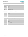
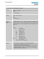
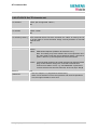
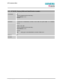
"AT Command Set" Version TC3x-ATC-01-V03.00=> TC3x5-ATC-01-03.10
Chapter
Page
AT command
What is new
1.4.2
12
2.13
2.37
2.20
2.26
2.46
2.46.1
3
25
35
27
30
41
42
43
Any command
AT+IPR
ATI[value]
AT&S
ATS0
ATS7
AT+IPR
AT+IPR
Fax commands
Maximum length of command line buffer added.
To be used standalone.
Only value 9 supported
<value>2 removed
Notes added
Notes added
Recommendation added: To be used standalone.
List of bit rates detectable in autobaud mode
Note added: Autobauding recommended when using
standard PC Fax programs
TC3X_ATC_01_V04.00
Page 8 of 204
29.05.2002
AT Command Set
4.2
58
4.5
4.6
4.7
63
64
67
4.9
4.15
4.18
69
73
75
4.22
4.24
4.24.1
4.26
4.28
4.31 / 4.31.1
84
86
87
90
93
96 / 99
4.32
4.34
4.37
5.15
101
104
108
141
6.5
148
6.7
6.19
7.1.5- 7.1.14
7.1.3
7.2 / 7.3
152
162
181 - 193
185
194/196
TC3X_ATC_01_V04.00
AT+CALA
Alarm mode not applicable to TC35 Terminal.
RTC initialization after wake-up into Alarm mode
described.
AT+CBST
Transmission rate 14400 bps now supported.
AT+CCFC
Description revised, examples added
AT+CCLK
RTC initialization after wake-up into Alarm mode
described
AT+CFUN
Chapter revised
AT+CHUP
Note added: AT+CHUP implemented like ATH
AT+CLCK
Description revised, examples for phone security lock
types and call barring added
AT+CMEE
Setting not saved when ME is powered down
AT-CMUX
Overview on Multiplex mode updated
AT+CMUX
Restrictions on Multiplex mode updated
AT+COPS
Chapter revised
AT+CPBR
Description revised, examples added
AT+CPIN
Description revised. Summary of actions to be taken
after authentication failure
AT+CPIN2
Description revised, examples added
AT+CPWD
Description revised, examples added
AT+CREG
Description revised, examples added
AT+CSMP
Command
syntax
corrected,
first
parameter
mandatory
AT^SBC
Default setting of <current> described
Automatic shutdown explained in more detail
AT^SCKS
URC not stored when ME is powered down
AT^M20
Description revised
Several AT+CEER location Ids and release causes added
URCs
Further explanations relating to URCs
Usability of AT commands with or without PIN authentication: Both lists
updated
Page 9 of 204
29.05.2002
AT Command Set
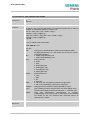
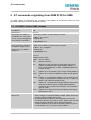
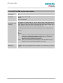
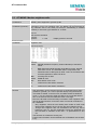
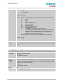
1 Introduction
1.1
Scope of the document
This document presents the AT Command Set for the Siemens cellular engines
TC35 Module
TC37 Module
TC35 Terminal
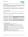
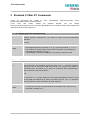
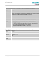
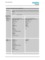
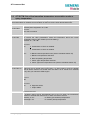
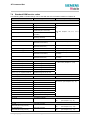
The AT commands detailed in this document are generally supported by all products. Where
differences occur, they are noted in the chapter that refers to the command. In the present version, the
only exceptions concern the following commands:
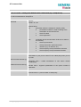
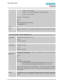
Table 1: Product specific use of AT commands
AT command
AT+CALA, Chapter 4.2
TC35 / TC37 Modules
TC35 Terminal
Alarm mode and reminder call fully Does not support Alarm mode.
applicable
Please ignore any information
relating to the subject.
The reminder call can be used as
described.
AT^SSYNC, Chapter 6.39
SYNC pin may be assigned
different functions: <mode> 0 or 1.
SYNC pin supports only <mode>=1
(LED status).
AT^SBC, Chapter 6.5
All functions fully applicable
Command not applicable.
1.2
Supported product versions and related documents
Please note that TC35, TC37 Modules and TC35 Terminal are using the same firmware, referred to as
TC35. The present AT Command Set applies to all products based on the TC35 software version
04.00.
Related documents
[1] TC35 / TC37 Hardware Interface Description (applies to TC35 and TC37)
[2] TC3x Release Notes related to TC35 software version 04.00 (applies to TC35, TC37 and TC35T)
[3] TC3x Multiplexer User's Guide (applies to TC35, TC37 and TC35T)
[4] Application Note 16: Updating TC35 Firmware (applies to TC35, TC37 and TC35T)
[5] TC35 Terminal Hardware Interface Description (applies to TC35T)
[6] TC35 MC35 Terminal User's Guide (applies to TC35T and MC35T)
[7] Application Note 02: Audio Interface (applies to TC35, TC37 and TC35T)
Prior to using TC35 /TC37 or TC35T or upgrading to a new firmware release, be sure to carefully read
the latest product information provided in the Release Notes.
To visit the Siemens Website you can use the following link:
http://www.siemens.com/wm
TC3X_ATC_01_V04.00
Page 10 of 204
29.05.2002
AT Command Set
1.3
Conventions
Throughout the document, the GSM engines are referred to as ME (Mobile Equipment), MS (Mobile
Station), TA (Terminal Adapter), DCE (Data Communication Equipment) or facsimile DCE (FAX
modem, FAX board). When the Siemens product names are required to distinguish the two models,
TC3x is short for the engine type and TC35T for the terminal.
To control your GSM engine you can simply send AT Commands via its serial interface. The
controlling device at the other end of the serial line is referred to as TE (Terminal Equipment), DTE
(Data Terminal Equipment) or plainly ´the application´ (probably running on an embedded system).
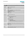
1.4
AT command syntax
The "AT" or "at" prefix must be set at the beginning of each command line. To terminate a command
line enter <CR>.
Commands are usually followed by a response that includes “<CR><LF><response><CR><LF>”.
Throughout this document, only the responses are presented, <CR><LF> are omitted intentionally.
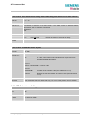
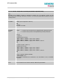
Table 2: Types of AT commands and responses
Test command
AT+CXXX=?
Read command
AT+CXXX?
Write command
Execution command
AT+CXXX=<...>
AT+CXXX
The mobile equipment returns the list of parameters and
value ranges set with the corresponding Write command
or by internal processes.
This command returns the currently set value of the
parameter or parameters
This command sets user-definable parameter values.
The execution command reads non-variable parameters
affected by internal processes in the GSM engine.
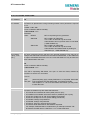
1.4.1 Using parameters
· Default parameters are underlined throughout this document.
· Optional parameters are enclosed in square brackets. If optional parameters are omitted, the
current settings are used until you change them.
· Optional parameters or subparamters can be omitted unless they are followed by other
parameters. If you want to omit a parameter in the middle of a string it must be replaced by a
comma. Example:
AT+CPBW=,<number>,<type>,<text> writes a phonebook entry to the first free memory location.
AT+CPBW=<index>,<number>,<type>,<text> writes a phonebook entry to the memory location
specified by <index>.
· When the parameter is a character string, e.g. <text> or <number>, the string must be enclosed in
quotation marks, e.g. "Charlie Brown" or "+49030xxxx". Symbols within quotation marks will be
recognized as strings.
· All spaces will be ignored when using strings without quotaton marks.
· It is possible to omit the leading zeros of strings which represent numbers.
· In case of using V.25ter commands without giving an optional parameter, its value is assumed to
be 0.
TC3X_ATC_01_V04.00
Page 11 of 204
29.05.2002
AT Command Set
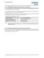
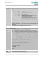
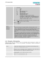
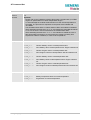
1.4.2 Combining AT commands on the same command line
You may enter several AT commands on the same line. This eliminates the need to type the "AT" or
"at" prefix before each command. Instead, it is only needed once at the beginning of the command
line. Use a semicolon as command delimiter.
The command line buffer accepts a maximum of 391 characters. If this number is exceeded none of
the commands will be executed and TA returns ERROR.
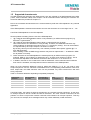
The table below lists the AT commands you cannot enter together with other commands on the same
line. Otherwise, the responses may not be in the expected order.
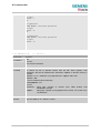
Table 3: Illegal combinations of AT commands
V.25ter commands
GSM 7.07 commands
GSM 7.05 commands (SMS)
Commands starting with AT&
AT+IPR
With
With
-------
FAX commands, Prefix AT+F
Siemens commands, Prefix AT^S
To be used standalone
To be used standalone
To be used standalone
Note: Generally, appending the same or mixed AT commands should be avoided. If nevertheless
you need to do enter several commands on the same line, note that the number of subsequent
commands is limited.
1.4.3 Entering successive AT commands on separate lines
When you enter a series of AT commands on separate lines, leave a pause between the preceding
and the following command until OK appears. This avoids sending too many AT commands at a time
without waiting for a response for each.
TC3X_ATC_01_V04.00
Page 12 of 204
29.05.2002
AT Command Set
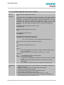
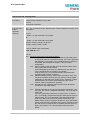
1.5
Supported character sets
The ME supports two character sets: GSM 03.38 (7 bit, also referred to as SMS alphabet) and UCS2
(16 bit, refer to ISO/IEC 10646). See Chapter 4.40 for information about selecting the character set.
Character tables are provided in Chapter 7.5.
Due to the constraints described below it is recommended to prefer the USC2 alphabet in any external
application.
If the GSM alphabet is selected all characters sent over the serial line are in the range from 0 ... 127.
CAUTION: GSM alphabet is not ASCII alphabet!
Several problems resulting from the use of the GSM alphabet:
1. "@" character with GSM alphabet value 0 is not printable by an ASCII terminal program (e.g.
©
®
Microsoft Hyperterminal ).
2. "@" character with GSM alphabet value of binary 0 will terminate any C string!
This is because the \0 is defined as C string end tag. Therefore, the GSM Null character may
cause problems on application level when using a ´C´-function as „strlen()“. This can be avoided if
it is represented by an escape sequence as shown in Table 4.
By the way, this may be the reason why even network providers often replace "@"with “@=*” in
their SIM application.
When sending e-mails via SMS the @ character may also be replaced with “*” as defined in GSM
03.40 (3GPP TS 23.040).
3. Other characters of the GSM alphabet are misinterpreted by an ASCII terminal program. For
example, GSM "ö" (as in "Börse") is assumed to be "|" in ASCII, thus resulting in "B|rse". This is
because both alphabets mean different characters with values hex. 7C or 00 and so on.
4. In addition, decimal 17 and 19 which are used as XON/XOFF control characters when software
flow control is activated, are interpreted as normal characters in the GSM alphabet.
When you write characters differently coded in ASCII and GSM (e.g. Ä, Ö, Ü), you need to enter
escape sequences. Such a character is translated into the corresponding GSM character value and,
when output later, the GSM character value can be presented. Any ASCII terminal then will show
wrong responses.
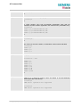
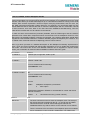
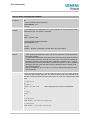
Table 4: Character definitions depending on alphabet (examples)
GSM 03.38
character
Ö
"
ò
@
GSM character
hex. value
5C
22
08
00
Corresponding
ASCII character
\
“
BSP
NULL
ASCII
Esc sequence
\5C
\22
\08
\00
Hex
Esc sequence
5C 35 43
5C 32 32
5C 30 38
5C 30 30
CAUTION: Often, the editors of terminal programs do not recognize escape sequences. In this case,
an escape sequence will be handled as normal characters. The most common workaround to this
problem is to write a script which includes a decimal code instead of an escape sequence. This way
you can write, for example, short messages which may contain differently coded characters.
TC3X_ATC_01_V04.00
Page 13 of 204
29.05.2002
AT Command Set
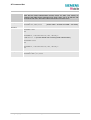
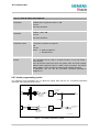
1.6
Flow control
Flow control is essential to prevent loss of data or avoid errors when, in a data or fax call, the sending
device is transferring data faster than the receiving side is ready to accept. When the receiving buffer
reaches its capacity, the receiving device should be capable to cause the sending device to pause
until it catches up.
There are basically two approaches to regulate data flow: software flow control and hardware flow
control. The High Watermark of the input / output buffer should be set to approximately 60% of the
total buffer size. The Low Watermark is recommended to be about 30%. The data flow should be
stopped when the capacity rises close to the High Watermark and resumed when it drops below the
Low Watermark. The time required to cause stop and go results in a hysteresis between the High and
Low Watermarks.
In Multiplex mode, it is recommended to use hardware flow control. For details please refer to [3].
1.6.1 Software flow control (XON/OFF flow control)
Software flow control sends different characters to stop (XOFF, decimal 19) and resume (XON,
decimal 17) data flow. The only advantage of software flow control is that three wires would be
sufficient on the serial interface.
1.6.2 Hardware flow control (RTS/CTS flow control)
Hardware flow control sets or resets the RTS/CTS wires. This approach is faster and more reliable,
and therefore, the better choice. When the High Watermark is reached, CTS is set inactive until the
transfer from the buffer has completed. When the Low Watermark is passed, CTS goes active once
again.
To achieve smooth data flow, ensure that the RTS/CTS lines are present on your application platform.
The application should include options to enable RTS/CTS handshake with the GSM engine. This
needs to be done with the AT command AT\Q3 - it is not sufficient to set RTS/CTS handshake in the
used Terminal program only.
The default setting of the GSM engine is AT\Q0 (no flow control) which must be altered to AT\Q3
(RTS/CTS hardware handshake on). The setting is stored volatile and must be restored each time
after the GSM engine was switched off. For further details refer to Chapter 2.3.
AT\Q has no read command. To verify the current setting of AT\Q, simply check the settings of the
active profile with AT&V.
Often, fax programs run an intialization procedure when started up. The intialization commonly
includes enabling RTS/CTS hardware handshake, eliminating the need to set AT\Q3 once again.
However, before setting up a CSD call, you are advised to check that RTS/CTS handshake is set.
Note:
After deactivating the RTS line, the ME may still send up to 32 bytes. This can be easily
handled if the buffer of the host application is sufficiently sized, and if a hysteresis is
implemented in its Rx buffer as mentioned in Chapter 1.6. A total buffer capacity of 256 bytes
has been proved to work well.
TC3X_ATC_01_V04.00
Page 14 of 204
29.05.2002
AT Command Set
2 Standard V.25ter AT Commands
These AT Commands are related to ITU-T (International Telecommunication Union,
Telecommunication sector) V.25ter document.
TC35,
TC37
and
TC35T
support
the
registers
S0-S29.
You
can
change
S0,S3,S4,S5,S6,S7,S8,S10,S18 by using the appropriate ATSn commands. All the other registers are
read-only and for internal usage only!
2.1
A/ Repeat previous command line
Execute command
Response
A/
Repeats previous command line. Line does not need to end with terminating
character.
Parameter
Reference
Note
V.25ter
· After beginning with the character “a“ or „A“, a second character “t“ ,”T“ or “/“
has to follow. In case of using a wrong second character, it is necessary to
start again with character “a“ or “A“.
· If autobauding is active (see +IPR, pg. 40) A/ (and a/) cannot be used.
2.2
+++ Switch from data mode to command mode
Execute command
Response
+++
This command is only available during data calls. The +++ character sequence
causes the TA to cancel the data flow over the AT interface and switch to
command mode. This allows you to enter AT commands while maintaining the
data connection to the remote device.
OK
To prevent the +++ escape sequence from being misinterpreted as data, it must
be preceded and followed by a pause of at least 1000 ms. The +++ characters
must be entered in quick succession, all within 1000 ms.
Reference
Note:
V.25ter
· To return from on-line command mode to on-line data mode: Enter ATO as
described in Chapter 2.17.
TC3X_ATC_01_V04.00
Page 15 of 204
29.05.2002
AT Command Set
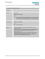
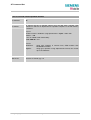
2.3
AT\Qn Flowcontrol
Execute command
Response
AT\Q<n>
OK
Parameter
<n>
Reference
0
AT\Q0
No flow control
1
AT\Q1
XON/XOFF software flow control
2
AT\Q2
Only CTS by DCE
3
AT\Q3
RTS/CTS hardware flow control
Required for the following procedures: incoming
or outgoing data calls, fax calls.
Often, the initialization routine of Fax programs
includes enabling RTS/CTS handshake,
eliminating the need to issue AT\Q3 once again.
Note
Line state refers to RS-232 levels.
The setting of AT\Q is stored volatile and must be restored each time after the
GSM engine was switched off. Also, there is no way to store AT\Q to the user
defined profile.
See also Chapter 1.6 for general information on flow control.
2.4
ATA Answer a call
Execute command
ATA
TA causes remote station to go off-hook (e.g. answer call).
Note1:
Any additional commands on the same command line are ignored.
Note2:
This command may be aborted generally by receiving a character during
execution. It can´t be aborted in some connection setup states, such as
handshaking.
Response
Response in case of data call, if successfully connected:
CONNECT<text> TA switches to data mode.
Note: <text> output only if +ATX parameter setting with value > 0.
Response in case of voice call, if successfully connected:
OK
When TA returns to command mode after call release:
OK
Response if no connection:
NO CARRIER
Parameter
Reference
Note
V.25ter
See also AT+ATX and chapter 7.1.4 for <text>
TC3X_ATC_01_V04.00
Page 16 of 204
29.05.2002
AT Command Set
2.5
ATD Mobile originated call to dial a number
Execute command
ATD[<n>]
[<mgsm][;]
This command can be used to set up outgoing voice, data or fax calls. It also
serves to control supplementary services.
Note:
The command may be aborted generally when receiving an ATH command during
execution. It can´t be aborted in some connection setup states, such as
handshaking. Two different call setup options can be determined for voice calls:
TA returns OK either after dialing was completed or after call has been
established. The setting is made with AT^SM20 (see Chapter 6.19). In data
connections, call setup always terminates when the call has been established.
Response
If no dialtone (parameter setting ATX2 or ATX4):
NO DIALTONE
If busy (parameter setting ATX3 or ATX4):
BUSY
If a connection cannot be set up:
NO CARRIER
If successfully connected and non-voice call:
CONNECT<text> TA switches to data state.
Note:
<text> output only if +ATX parameter setting with value > 0.
When TA returns to command mode after call release:
OK
If successfully connected and voice call:
OK
Parameter
<n>
String of dialling digits and optionally V.25ter modifiers (dialling digits):
0-9, * , #, +, A, B, C
V.25ter modifiers: these are ignored: ,(comma), T, P, !, W, @
Emergency call:
<n>
= 112 worldwide number (no SIM needed)
<mgsm> String of GSM modifiers:
I Activates CLIR (disables presentation of own phone number to called
party)
i Deactivates CLIR (enables presentation of own phone number to
called party)
<;>
Only required to set up voice calls. TA remains in command mode.
Reference
Note
V.25ter/GSM
07.07
· Before setting up a data call, check that RTS/CTS handshake is enabled. See
Chapters 1.6 and 2.3.
· Parameter “l“ and “i“ only if no *#-code is within the dial string.
· <mgsm> is not supported for data calls.
· <n> is default for last number that can be dialled by ATDL.
· See also +ATX and chapter 7.1.4 for <text>.
· The *# codes can only be used with voice calls (i.e. use ´; ´) only.
· If ATD is used with a USSD command (e.g. ATD*100#;) an AT+CUSD=1 is
executed implicitly. (see AT+CUSD, pg. 116).
TC3X_ATC_01_V04.00
Page 17 of 204
29.05.2002
AT Command Set
2.6
ATD><mem><n> Originate call to phone number <n> in memory <mem>
This command allows you to dial a phone number from a specific phonebook. To initiate a call, enter
a two letter abbreviation for the phonebook <mem>, followed by the memory location <n> of the
desired entry. The location range of each phonebook can be queried by AT+CPBR (see Chapter
4.28).
Execute command
ATD><mem>
<n>[<mgsm>][;]
TA attempts to set up an outgoing call to the specified number.
Note:
This command may be aborted generally by receiving a character during
execution. Abortion is not possible during some states of connection
setup such as handshaking.
Response
If error is related to ME functionality:
+CME ERROR: <err>
If no dialtone (parameter setting ATX2 or ATX4):
NO DIALTONE
If busy (parameter setting ATX3 or ATX4):
BUSY
If connection cannot be set up:
NO CARRIER
If successfully connected and non-voice call:
CONNECT<text> TA switches to data state.
Note: <text> output only if +ATX parameter setting with value > 0.
When TA returns to command mode after call release:
OK
If successfully connected and voice call:
OK
Parameter
<mem> phonebook:
"SM” SIM phonebook (storage depending on SIM card)
”FD” SIM fixdialling phonebook (pos. 1-7)
”LD” SIM last-dialling-phonebook (usually the last 10 numbers
dialed are stored on the SIM card, no matter whether or not the
calls were successfully set up)
”MC” ME missed (unanswered received) calls list (up to 10 numbers)
”RC” SIM received calls list
”ME” ME Phonebook (up to 50 numbers)
”ON” SIM (or ME) own numbers (MSISDNs) list
Note: <mem> must be included in quotation marks (""), if parameter
<mgsm> is used. If not, quotation marks are optional.
<n>
Integer type memory location in the range of locations available in
the selected memory, i.e. the index number returned by AT+CPBR.
<mgsm>
I
TC3X_ATC_01_V04.00
Activates CLIR (disables presentation of own phone number to
called party)
Page 18 of 204
29.05.2002
AT Command Set
i
<;>
Deactivates CLIR (enables presentation of own phone number
to called party)
Only required to set up voice calls. TA remains in command mode.
Reference
Note
V.25ter/GSM
07.07
·
·
·
·
·
Example
To query the location number of the phonebook entry:
AT+CPBR=1,xx
There is no <mem> for emergency call (“EN”).
Command is not supported for data call!
Parameter <mgsm> only if no *# code is within the dial string.
The *# codes can only be used with voice calls (i.e.if “;” is appended).
See also ATX and chapter 7.1.4 for <text>.
TA returns the entries available in the active phonebook.
To dial a number from the SIM phonebook, for example the number stored to
location 15:
ATD>SM15;
OK
To dial a phone number stored in the last dial memory on the SIM card:
ATD>LD9;
OK
TC3X_ATC_01_V04.00
Page 19 of 204
29.05.2002
AT Command Set
2.7
ATD><n> Originate call to phone number selected from active memory
This command can be used to dial a phone number selected from the active memory. The active
memory is the phonebook selected with AT+CPBS (see Chapter 4.29). To set up a call simply enter
the memory location of the desired entry. The memory location range of each phonebook can be
queried by AT+CPBR (see Chapter 4.28).
Execute command
ATD><n>[<mgsm>][;]
TA attempts to set up an outgoing call to the stored number.
Note: This command may be aborted generally by receiving a character
during execution. It can´t be aborted in some connection setup states,
such as handshaking.
Response
If error is related to ME functionality:
+CME ERROR: <err>
If no dialtone (parameter setting ATX2 or ATX4):
NO DIALTONE
If busy (parameter setting ATX3 or ATX4):
BUSY
If a connection cannot be set up:
NO CARRIER
If successfully connected and non-voice call:
CONNECT<text> TA switches to data state.
Note: <text> output only if +ATX parameter setting with value > 0.
When TA returns to command mode after call release:
OK
If successfully connected and voice call:
OK
Parameter
<n>
integer type memory location should be in the range of locations
available in the memory used, i.e. the index number returned by
AT+CPBR.
<mgsm> I Activates CLIR (disables presentation of own phone number to
called party)
i Deactivates CLIR (enables presentation of own phone number
to called party)
<;>
Reference
Note
V.25ter/GSM 07.07
·
·
·
·
TC3X_ATC_01_V04.00
Only required to set up voice calls. TA remains in command mode.
Parameter <mgsm> only if no *# code is within the dial string.
Command is not supported for data call!
The *# codes can only be used with voice calls (i.e.if “;” is appended).
See also +ATX and chapter 7.1.4 for <text>.
Page 20 of 204
29.05.2002
AT Command Set
2.8
ATD><str> Originate call to phone number in memory with
corresponding field
This command searches the active phonebook for a given string <str> and dials the assigned phone
number. The active phonebook is the one set with AT+CPBS.
Execute command
TA attempts to set up an outgoing call to stored number
ATD><str>[mgsm][;] Note: This command may be aborted generally by receiving a character
during execution. It can´t be aborted in some connection setup states,
such as handshaking.
Response
If error is related to ME functionality:
+CME ERROR: <err>
If no dialtone (parameter setting ATX2 or ATX4):
NO DIALTONE
If busy (parameter setting ATX3 or ATX4):
BUSY
If a connection cannot be set up:
NO CARRIER
If successfully connected and non-voice call:
CONNECT<text> TA switches to data state.
Note: <text> output only if +ATX parameter setting with value > 0.
When TA returns to command mode after call release:
OK
If successfully connected and voice call:
OK
Parameter
string type value (“x”), which should equal an alphanumeric field in
at least one phonebook entry in the searched memories; used
character set should be the one selected with Select TE Character
Set +CSCS. <str> can contain escape sequences as described in
chapter „“, pg. 11.
<str> must be wrapped in quotation marks (""), if escape sequences
or parameter <mgsm> are used or if the alphanumeric strings
contains a blank. If not, quotation marks are optional.
<mgsm> I Activates CLIR (disables presentation of own phone number to
called party)
i Deactivates CLIR (enables presentation of own phone number to
called party)
<;>
Only required to set up voice calls. TA remains in command mode.
<str>
Reference
Note
V.25ter/GSM 07.07
Command is not supported for data calls! See also ATX and Chapter 7.1.4 for
<text>
TC3X_ATC_01_V04.00
Page 21 of 204
29.05.2002
AT Command Set
2.9
ATDI Mobile originated call to dialable ISDN number <n>
Execute command
ATDI<n>[;]
TA attempts to set up an outgoing call to ISDN number.
Note:
This command may be aborted generally by receiving a character during
execution. This command cannot be aborted in some connection setup
states, such as handshaking.
Response
If no dialtone (parameter setting ATX2 or ATX4):
NO DIALTONE
If busy (parameter setting ATX3 or ATX4):
BUSY
If a connection cannot be set up:
NO CARRIER
If successful connected and non-voice call:
CONNECT<text> TA switches to data state.
Note: <text> output only if +ATX parameter setting with value > 0.
When TA returns to command mode after call release:
OK
If successfully connected and voice call:
OK
Parameter
<n>
[+]<d>
phone number
string with maximum length of 20 characters
+
international dialling format
<d>
ISDN number
string of digits: +,0-9, A, B, C
<;>
voice call
Reference
V.25ter
TC3X_ATC_01_V04.00
Page 22 of 204
29.05.2002
AT Command Set
2.10 ATDL Redial last telephone number used
Execute command
ATDL[;]
This command redials the last voice and data call number used in the ATD
command.
· To redial the last data call number simply enter ATDL
· To redial the last voice call number type ATDL;
Note:
The command may be aborted generally by receiving a character during
execution. This command cannot be aborted in some connection setup
states, such as handshaking.
Response
If there is no last number or number is not valid:
+CME ERROR
If no dialtone (parameter setting ATX2 or ATX4):
NO DIALTONE
If busy (parameter setting ATX3 or ATX4):
BUSY
If a connection cannot be set up:
NO CARRIER
If successfully connected and non-voice call:
CONNECT<text> TA switches to data state.
Note: <text> output only if +ATX parameter setting with value > 0.
When TA returns to command mode after call release:
OK
If successfully connected and voice call:
OK
Parameter
<;>
voice call
Reference
Note
V.25ter
In case of voice calls “;” is necessary.
TC3X_ATC_01_V04.00
Page 23 of 204
29.05.2002
AT Command Set
2.11 ATE Enable command echo
Write command
ATE[<value>]
This setting determines whether or not the TA echoes characters received from
TE during command state.
Response
OK
Parameter
<value> 0 Echo mode off
1 Echo mode on
Reference
Note
V.25ter
In case of using the command without parameter, <value> is set to 0.
2.12 ATH Disconnect existing connection
Execute command
Disconnects any call in progress, such as voice calls, fax or CSD data calls.
ATH[n]
Response
OK
Note:
OK is issued after circuit 109 (DCD) is turned off (RS-232 level), if it was
previously on.
Parameter
<n>
0 terminate call
Reference
Note
V.25ter
Using ATH in Multiplex mode (AT+CMUX)
· ATH terminates every data call, even if it is issued via logical channels 2 or 3.
· This behaviour is in accordance with ITU-T V.25 ter; (07/97, see „6.3.6 Hook
control“: "ATH is terminating any call in progress.")
TC3X_ATC_01_V04.00
Page 24 of 204
29.05.2002
AT Command Set
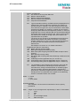
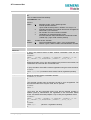
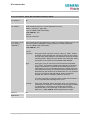
2.13 ATI Display product identification information
Execute command
Response
ATI
ME issues product information text
SIEMENS
REVISION TC35 x.yy
xx.yy
OK
Explanation of „Revision“ parameter: Version xx and variant yy of software
release.
Reference
Note
V.25ter
2.14 ATI[value] Display additional identification information
Execute command
Response
ATI[value]
Delivers no specific information and simply returns OK.
Reference
Note
V.25ter
TC3X_ATC_01_V04.00
Page 25 of 204
29.05.2002
AT Command Set
2.15 ATL Set monitor speaker loudness
Execute command
Response
ATL[val]
OK
Reference
Note
V.25ter
· The two commands ATL and ATM are implemented only for V.25ter
compatibility reasons and have no effect.
· In multiplex mode the command is supported on logical channel 1 only.
2.16 ATM Set monitor speaker mode
Execute command
Response
ATM[val]
OK
Reference
Note
V.25ter
· The two commands ATL and ATM are implemented only for V.25ter
compatibility reasons and have no effect.
· In multiplex mode the command is supported on logical channel 1 only.
2.17 ATO Switch from command mode to data mode
Execute command
Response
ATO[n]
ATO is the corresponding command to the +++ escape sequence described in
Chapter 2.2: When you have established a data call and TA is in command mode,
ATO causes the TA to resume the data connection and return to data mode.
If connection is not successfully resumed
NO CARRIER
or
TA returns to data mode from command mode CONNECT <text>
Note: <text> output only if +ATX parameter setting with value > 0.
Parameter
<n>
Reference
0 switch from command mode to data mode
Note
V.25ter
TC3X_ATC_01_V04.00
Page 26 of 204
29.05.2002
AT Command Set
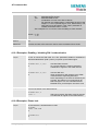
2.18 ATQ Set result code presentation mode
Write command
Response
ATQ[<n>]
Specifies whether or not the TA transmits any result code to the TE. Information
text transmitted in response is not affected by this setting.
If <n>=0:
OK
If <n>=1:
(none)
Parameter
<n>
0 DCE transmits result code
1 Result codes are suppressed and not transmitted
Reference
Note
V.25ter
2.19 ATP Select pulse dialling
Execute command
Response
ATP
OK
Reference
Note
V.25ter
No effect for GSM
2.20 ATS0 Set number of rings before automatically answering the call
Read command
Response
ATS0?
<n> OK
Write command
Specifies whether or not the TA will accept an incoming data / fax call without
user intervention. <n> determines the number of rings to wait before the TA will
automatically answer.
ATS0=<n>
Response
OK
Parameter
<n>
000
disables automatic answer mode
001-255 enables automatic answering after specified number of rings
Reference
Note
V.25ter
· Auto-answer mode is only applicable to data or fax calls.
· If <n> is set too high, the calling party may hang up before the call can be
automatically answered.
· The correlation between ATS7 and ATS0 is important.
Example: Call setup may fail if ATS0=20 and ATS7=30.
TC3X_ATC_01_V04.00
Page 27 of 204
29.05.2002
AT Command Set
2.21 ATS2 Escape code sequence
Read command
Response
ATS2?
S2 determines the decimal value of the ASCII character used in the escape code
sequence, which serves, during a data call, to change from data to command
mode. Compare Chapter 2.2.
The default value 043 is equivalent to an ASCII “+”. Please note that the value
cannot be changed, and therefore, test or write commands are not supported.
Reference
Note
V.25ter
2.22 ATS3 Write command line termination character
Read command
Response
ATS3?
<n> OK
This parameter setting determines the character recognized by TA to terminate
an incoming command line.
Write command
ATS3=<n>
Response
OK
Parameter
<n>
Reference
000-013-127
command line termination character
Note
V.25ter
2.23 ATS4 Set response formatting character
Read command
Response
ATS4?
<n> OK
Write command
This parameter setting determines the character generated by the TA for result
code and information text.
ATS4=<n>
Response
OK
Parameter
<n>
Reference
000-010-127
response formatting character.
Note
V.25ter
TC3X_ATC_01_V04.00
Page 28 of 204
29.05.2002
AT Command Set
2.24 ATS5 Write command line editing character
Read command
Response
ATS5?
<n> OK
Write command
This parameter setting determines the character recognized by TA as a request
to delete the immediately preceding character from the command line.
ATS5=<n>
Response
OK
Parameter
<n>
Reference
000-008-127
command line editing character
Note
V.25ter
2.25 ATS6 Set pause before blind dialling
Read command
Response
ATS6?
<n> OK
Write command
No effect for GSM
ATS6=<n>
Response
OK
Parameter
<n>
Reference
000-255 number of seconds to wait before blind dialling.
Note
V.25ter
TC3X_ATC_01_V04.00
Page 29 of 204
29.05.2002
AT Command Set
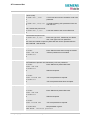
2.26 ATS7 Set number of seconds to wait for connection completion
Read command
Response
ATS7?
<n> OK
Write command
Specifies the number of seconds the TA will wait for the completion of the call
setup when answering or originating a data call. Also referred to as "no answer
timeout". To put it plainly, this is the time to wait for the carrier signal. If no carrier
signal is received within the specified time, the TA hangs up.
ATS7=<n>
Response
OK
Parameter
<n>0 <n>
000 – 060 no. of seconds to wait for connection completion.
Reference
Note
V.25ter
· Values greater than 60 cause no error, but <n> will be restored to the
maximum value of 60.
· If called party has specified a high value for ATS0=<n>, call setup may fail.
· The correlation between ATS7 and ATS0 is important.
Example: Call setup may fail if ATS7=30 and ATS0=20.
· ATS7 is only applicable to data calls.
2.27 ATS8 Set number of seconds to wait for comma dial modifier
Read command
Response
ATS8?
<n> OK
Write command
No effect for GSM
ATS8=<n>
Response
OK
Reference
Note
V.25ter
TC3X_ATC_01_V04.00
Page 30 of 204
29.05.2002
AT Command Set
2.28 ATS10 Set disconnect delay after indicating the absence of data carrier
Read command
Response
ATS10?
<n> OK
Write command
This parameter setting determines the amount of time, that the TA remains
connected in absence of a data carrier. If the data carrier is detected before
disconnect, the TA remains connected.
ATS10=<n>
Response
OK
Parameter
<n>
Reference
001-002-254
number of tenths of seconds of delay
Note
V.25ter
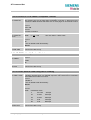
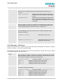
2.29 ATS18 Extended error report
Test command
Response
ATS18?
<n> OK
Execute command
TA returns an extended report of the reason for the last call release and location.
ATS18=<n>
<n>
0 – 255, odd numbers set extended error report and even
numbers disable this feature.
Response
+Cause: <location ID>: <reason > OK
Parameter
<location ID>
Location ID as number code (see subclause 7.1.5).
<reason>
Reason for last call release as number code (see subclause
7.1.5).
Reference
Note
Siemens
This command works for data calls only. For voice calls please use AT+CEER.
2.30 ATT Select tone dialling
Execute command
Response
ATT
OK
Reference
Note
V.25ter
No effect for GSM
TC3X_ATC_01_V04.00
Page 31 of 204
29.05.2002
AT Command Set
2.31 ATV Set result code format mode
Write command
Response
ATV[<value>]
This parameter setting determines the contents of the header and trailer
transmitted with result codes and information responses.
When <value> =0
0
When <value> =1
OK
Parameter
<value>
0 Information response: <text><CR><LF>
Short result code format: <numeric code><CR>
1 Information response: <CR><LF><text><CR><LF>
Long result code format: <CR><LF><verbose code><CR><LF>
Reference
Note
V.25ter
In case of using the command without parameter <value> will be set to 0.
Information responses described in chapter 7 (verbose code and numeric code).
2.32 ATX Set CONNECT result code format and call monitoring
Write command
Response
ATX[<value>]
This parameter setting determines whether or not the TA detects the presence of
dial tone and busy signal and whether or not TA transmits particular result codes.
OK
Parameter
<value>
0
CONNECT result code only returned, dial tone and busy
detection are both disabled
1
CONNECT<text> result code only returned, dial tone and busy
detection are both disabled
2
CONNECT<text> result code returned, dial tone detection is
enabled, busy detection is disabled
3
CONNECT<text> result code returned, dial tone detection is
disabled, busy detection is enabled
4
CONNECT<text> result code returned, dial tone and busy
detection are both enabled
Reference
Note
V.25ter
Related <text> see chapter 7.1.4.
TC3X_ATC_01_V04.00
Page 32 of 204
29.05.2002
AT Command Set
2.33 ATZ Set all current parameters to user defined profile
Execute command
Response
ATZ[<value>]
TA sets all current parameters to the user profile stored with AT&W (see Chapter
2.39 on page 37). If a connection is in progress, it will be terminated. The user
defined profile is stored to the non-volatile memory.
Note: If invalid, the user profile will be reset to the factory default profile. Any
additional commands on the same command line will be ignored. A delay of
300 ms is required before next command is sent, otherwise “OK” response may
be corrupted.
OK
Parameter
<value> 0 Reset to user profile
Reference
Note
V.25ter
The GSM engines referred to in this manual can be assigned two profiles: the
factory profile (restored with AT&F) and the user profile (stored with AT&W). See
Chapter 2.36 for details on AT&F.
2.34 AT&C Set circuit Data Carrier Detect (DCD) function mode
Write command
Response
AT&C[<value>]
This parameter determines how the state of circuit 109(DCD) relates to the
detection of received line signal from the distant end.
OK
Parameter
<value>
0
DCD line is always ON.
1
DCD line is ON in the presence of data carrier only.
Reference
Note
V.25ter
Line state refers to RS-232 levels.
TC3X_ATC_01_V04.00
Page 33 of 204
29.05.2002
AT Command Set
2.35 AT&D Set circuit Data Terminal Ready (DTR) function mode
Write command
Response
AT&D[<value>]
This command is only intended for data calls. The <value> parameter determines
how the TA responds when circuit 108/2 (DTR) is changed from ON to OFF
during data mode.
OK
Parameter
<value>
0
TA ignores status on DTR.
1
ON->OFF on DTR: Change to command mode while retaining
the connected call.
2
ON->OFF on DTR: Disconnect data call, change to command
mode. During state DTR = OFF is auto-answer off.
Reference
Note
V.25ter
Line state refers to RS-232 levels.
2.36 AT&F Set all current parameters to manufacturer defaults
Execute command
Response
AT&F[value]
TA sets all current parameters to the manufacturer defined profile.
OK
Parameter
<value>
0
set all TA parameters to manufacturer default
Reference
Note
V.25ter
· List of parameters reset to manufacturer default (sorted by the associated AT
commands):
E, Q, V, X, +CBST, +CRLP, +CRC, +CR, +CNMI, +CMEE, +CSMS, ^SCKS,
^SACM, +CREG, +CLIP, the S Parameters, &D, &C, &S
· In addition to the default profile, you can store an individual one with AT&W. To
alternate between the two profiles enter either ATZ (loads user profile) or AT&F
(restores factory profile). Refer to Chapter 2.39 for AT&W and Chapter 2.33 for
ATZ.
TC3X_ATC_01_V04.00
Page 34 of 204
29.05.2002
AT Command Set
2.37 AT&S Set circuit Data Set Ready (DSR) function mode
Write command
Response
AT&S<value>
This parameter determines how the TA sets circuit 107 (DSR) depending on the
communication state of the TA interfacing TE.
OK
Parameter
<value>
0
DSR always on.
1
TA in command mode: DSR is OFF.
TA in data mode: DSR is ON.
Reference
Note
V.25ter
Line state refers to RS-232 levels.
TC3X_ATC_01_V04.00
Page 35 of 204
29.05.2002
AT Command Set
2.38 AT&V Display current configuration
Execute command
Response
AT&V[<n>]
TA returns the current parameter setting. The configuration varies depending on
whether or not PIN authentication has been done, or Multiplex mode has been
activated.
Parameter
Configuration
without Multiplex
mode or
configuration on
channel 1 if
Multiplex mode
is enabled
Logical channels
2 and 3
(Multiplex mode
enabled)
<n>
0 profile number
PIN entered (see AT+CPIN, pg. 95)
ACTIVE PROFILE:
E1 Q0 V1 X4 &C1 &D2 &S0 \Q0
S0:000 S3:013 S4:010 S5:008 S6:000 S7:060
S8:000 S10:002 S18:000
+CBST: 7,0,1
+CRLP: 61,61,78,6
+CR: 0
+FCLASS: 0
+CRC: 0
+CMGF: 0
+CNMI: 0,0,0,0,1
+ILRR: 0
+IPR: 0
+CMEE: 0
^SMGO: 0,0
+CSMS: 0,1,1,1
^SACM: 0,"000000","000000"
^SCKS: 0,1
+CREG: 0,1
+CLIP: 0,2
+CAOC: 0
+COPS: 0,0,"operator"
OK
+CRC: 0
+CMGF: 0
+CNMI: 0,0,0,0,1
+ILRR: 0
+IPR: 19200
+CMEE: 0
^SMGO: 0,0
+CSMS: 0,1,1,1
^SACM: 0,"000000","000000"
^SCKS: 0,1
+CREG: 0, 1
+CLIP: 0,2
+CAOC: 0
+COPS: 0,0,"operator"
PIN not entered
ACTIVE PROFILE:
E1 Q0 V1 X4 &C1 &D2 &S0 \Q0
S0:000 S3:013 S4:010 S5:008 S6:000 S7:060
S8:000 S10:002 S18:000
+CBST: 7,0,1
+CRLP: 61,61,78,6
+CR: 0
+FCLASS: 0
+ILRR: 0
+IPR: 0
+CMEE: 0
^SCKS: 0,1
OK
+ILRR: 0
+IPR: 19200
+CMEE: 0
^SCKS: 0,1
OK
OK
Reference
Note:
TC3X_ATC_01_V04.00
Parameter values and order are subject to change.
Page 36 of 204
29.05.2002
AT Command Set
2.39 AT&W Store current configuration to user defined profile
Execute command
TA stores the current settings to a user defined profile in the non-volatile memory.
AT&W[<n>]
Response
OK or if error is related to ME functionality: ERROR / +CME ERROR: <err>
Parameter
<n>
0 number of profile
Reference
Note
V.25ter
The user defined profile will be loaded automatically after PowerUp. Use ATZ to
restore user profile and AT&F to restore factory settings. Until the first use of
AT&W, ATZ works as AT&F. See Chapter 2.33 for details on ATZ and Chapter
2.36 for AT&F.
List of settings stored to user defined profile:
· ATE, ATQ, ATV, ATX, AT+CRC, AT+CMGF, AT+CSDH, AT+CNMI, AT+ILRR,
AT+CMEE, AT^SMGO, AT+CSMS, AT^SACM, ^SCKS, AT+CREG, AT+CLIP,
AT+COPS.
AT&C, AT&D, AT&S, ATS0, ATS3, ATS4, ATS5, ATS6, ATS7, ATS8, ATS10,
ATS18, AT+FCLASS, AT+CBST, AT+CRLP, AT+CR.
User defined profiles in multiplex mode:
· On each multiplexer channel you can save an individual profile.
· List of settings stored to profile on multiplexer channel 1:
ATE, ATQ, ATV, ATX, AT+CRC, AT+CMGF, AT+CSDH, AT+CNMI, AT+ILRR,
AT+CMEE, AT^SMGO, AT+CSMS, AT^SACM, ^SCKS, AT+CREG, AT+CLIP,
AT+COPS.
AT&C, AT&D, AT&S, ATS0, ATS3, ATS4, ATS5, ATS6, ATS7, ATS8, ATS10,
ATS18, AT+FCLASS, AT+CBST, AT+CRLP, AT+CR.
· List of settings stored to profile on multiplexer channels 2 and 3:
ATE, ATQ, ATV, ATX, AT+CRC, AT+CMGF, AT+CSDH, AT+CNMI, AT+ILRR,
AT+CMEE, AT^SMGO, AT+CSMS, AT^SACM, ^SCKS, AT+CREG, AT+CLIP,
AT+COPS. (Parameters for data call are not relevant on channels 2 and 3.)
TC3X_ATC_01_V04.00
Page 37 of 204
29.05.2002
AT Command Set
2.40 AT+GCAP Request complete TA capabilities list
Test command
Response
AT+GCAP=?
OK
Parameter
Execute command
Response
AT+GCAP
TA reports a list of additional capabilities.
+GCAP: <name>
OK
Parameter
<name> e.g.: +CGSM,+FCLASS
Reference
Note
V.25ter
+CGSM: The response text shows which GSM commands of the ETSI standard
are supported.
2.41 AT+GMI Request manufacturer identification
Test command
Response
AT+GMI=?
OK
Execute command
Response
AT+GMI
TA reports information to identify the manufacturer.
SIEMENS
OK
Reference
Note
V.25ter
See also ”AT+CGMI Request manufacturer identification”.
2.42 AT+GMM Request TA model identification
Test command
Response
AT+GMM=?
OK
Execute command
TA reports one or more lines of information text which permit the user to identify
the specific model of device.
TC35
OK
AT+GMM
Reference
Note
V.25ter
See also ”AT+CGMM Request model identification”.
TC3X_ATC_01_V04.00
Page 38 of 204
29.05.2002
AT Command Set
2.43 AT+GMR Request TA revision identification of software status
Test command
Response
AT+GMR=?
OK
Execute command
Response
AT+GMR
TA returns product software version identification text.
REVISION x.yy
OK
x.yy
Version x and variant yy of software release.
Reference
Note
V.25ter
See also AT+CGMR Request revision identification of software status
2.44 AT+GSN Request TA serial number identification(IMEI)
Test command
Response
AT+GSN=?
OK
Execute command
Response
AT+GSN
TA reports one or more lines of information text which permit the user to identify
the individual device.
<sn>
OK
Parameter
<sn>
IMEI of the telephone(International Mobile station Equipment Identity)
Reference
Note
V.25ter
The serial number (IMEI) varies for every individual ME device.
TC3X_ATC_01_V04.00
Page 39 of 204
29.05.2002
AT Command Set
2.45 AT+ILRR Set TE-TA local rate reporting
Test command
Response
AT+ILRR=?
+ILRR: (list of supported <value>s) OK
Parameter
See write command
Read command
Response
AT+ILRR?
+ILRR: <value> OK
Parameter
See write command
Write command
AT+ILRR=
<value>
The write command specifies whether or not an intermediate result code shall
indicate the currently used local rate when an incoming or outgoing data call is
established. The message is transmitted from the DCE (= TA) to the DTE (=TE)
before the final result code of the connection setup (e.g. CONNECT) appears.
Response
OK
Parameter
<value> 0 Disables reporting of local port rate
1 Enables reporting of local port rate
Intermediate result code
+ILLR:<rate>
Parameter
<rate>
port rate setting in bit per second
0 (Autobauding, see Chapter 2.46.1)
300
600
1200
2400
4800
9600
14400
19200
28800
38400
57600
115200
Reference
Note
V.25ter
Example
ATD030112233445
+ILRR: 57600
CONNECT 9600/RLP
TC3X_ATC_01_V04.00
Page 40 of 204
29.05.2002
AT Command Set
2.46 AT+IPR Set fixed local rate
Test command
Response
AT+IPR=?
+IPR: (list of supported auto-detectable <rate>s), (list of supported fixed-only
<rate>s) OK
Parameter
See write command
Read command
Response
AT+IPR?
+IPR: <rate> OK
Parameter
See write command
Write command
AT+IPR=<rate>
This command specifies the DTE-DCE bitrate. When you set a fix rate, make sure
that both DTE (TE) and DCE (= TA) are configured to the same rate. When you
select autobauding the DCE will automatically recognize the bitrate currently used
by the DTE.
A selected bitrate takes effect following the issue of any result code associated
with this command (e.g. OK).
The setting is stored in the non-volatile memory and will be used whenever the
engine is powered up again. However, in case of autobaud mode (+IPR=0) the
detected DCE bitrate will not be saved and, therefore, needs to be be resynchronized after restarting the GSM engine (see Chapter 2.46.1).
Response
OK or if error is related to ME functionality: ERROR / +CME ERROR: <err>
Parameter
<rate> bit rate per second
0 (Autobauding, see Chapter 2.46.1)
300
600
1200
2400
4800
9600
14400
19200
28800
38400
57600
115200
Reference
Note
V.25ter
Your current setting of AT+IPR will be preserved
· when you download new firmware (i.e. a firmware update does not restore the
factory setting);
· in the event of power failure.
Generally, AT+IPR=x should be used as a standalone command. If nevertheless
combinations with other commands on the same line cannot be avoided, there are
several constraints to be considered:
· Avoid combinations with the AT commands listed in Chapter 1.4.2.
TC3X_ATC_01_V04.00
Page 41 of 204
29.05.2002
AT Command Set
· Take into account that a delay of 100 ms is required between a response to the
last command (e.g. OK) and the next command on the same line.
· When you enter AT+IPR=0, autobauding will be activated after the response to
the last command is received.
· When local echo is active (ATE1) and you enter AT+IPR=x with other
commands you may encounter the following problem: If switching to the new
bit rate takes effect while a response is being transmitted, the last bytes may
be sent at the new bit rate and thus, not properly transmitted. The following
commands will be correctly sent at the new bit rate.
2.46.1 Autobauding
Autobauding allows the GSM engine to automatically detect the bitrate configured in the host
application. The serial interface of the GSM engine supports autobauding for the following bitrates:
1200, 2400, 4800, 9600, 19200, 38400, 57600, 115200. Factory setting is autobauding enabled. This
gives you the flexibility to put the GSM engine into operation no matter what bitrate your host
application is configured to.
To take advantage of autobaud mode specific attention must be paid to the following requirements:
Synchronization between DTE and DCE
Ensure that DTE and DCE are correctly synchronized and the bitrate used by the DTE is detected by
the DCE (= ME). To allow the bitrate to be synchronized simply issue an "AT" or "at" string. This is
necessary
· after you have activated autobauding
· when you start up the GSM engine while autobauding is enabled. It is recommended to wait 3 to 5
seconds before sending the first AT character. Otherwise undefined characters might be returned.
If you want to use autobauding and autoanswer at the same time, you can easily enable the
synchronization, when you activate autobauding first and then configure the autoanswer mode
(ATS0=0).
Restrictions on autobauding operation
· The serial interface has to be operated at 8 data bits, no parity and 1 stop bit (factory setting).
· The A/ command (and a/) cannot be used.
· Only the strings „AT“ or „at“ can be detected (neither „aT“ nor „At“).
· The Unsolicited Result Codes "^SYSSTART", "^SYSSTART ALARM MODE" and "^SYSSTART
CHARGE-ONLY MODE" are not indicated when you start up the ME while autobauding is enabled.
This is due to the fact that the new bitrate is not detected unless DTE and DCE are correctly
synchronized as described above.
· Any other Unsolicited Result Codes that may be issued before the ME detects the new bitrate (by
receiving the first AT command string) will be sent at the previous bitrate.
· It is not recommended to switch to autobauding from a bitrate that cannot be detected by the
autobaud mechnism (e.g. 300 baud). Responses to +IPR=0 and any commands on the same line
might be corrupted.
· When entering several AT commands on the same line, consider the requirements described in the
Notes of Chapter 2.46.
· See also AT+ILRR Set TE-TA local rate reporting , pg. 39
Autobauding and multiplex mode
If autobauding is active you cannot switch to multiplex mode (see +CMUX, pg. 86). Vice versa, when
you run the multiplex mode, the write command AT+IPR=<rate> cannot be used.
TC3X_ATC_01_V04.00
Page 42 of 204
29.05.2002
AT Command Set
3 AT Commands for FAX
The following commands can be used for FAX transmission.
If the ME is acting as a Fax-Modem to a PC-based application (e.g. „WinFax“) it is necessary to select
the proper Service Class (Fax Class) provided by the ME. The ME reports its Service Class
capabilities, both the current setting and the range of services available. This is provided by the
AT+FCLASS command (see pg. 45).
Note: When sending a FAX with a standard FAX application for Personal Computers it is
recommended to use Autobauding (AT+IPR=0).
ME
C
C
Currently defined Service Class values (see TIA/EIA-592-A)
+FCLASS parameter Service Class
Reference, Standard
e.g. TIA/EIA-602 or ITU V.25ter
0
data modem
1
1.0
2
C
2.0
2.1
8
Reserved
Service Class 1
EIA/TIA-578-A
Service Class 1
manufacture specific
ITU-T T.31
this document and EIA PN-2388 (draft)
Service Class 2
Service Class 2
Voice DCE
TIA/EIA-592
TIA/EIA-592-A or ITU-T T.32
TIA IS-101
Note: Be aware that there is a difference between Service Classes 2 and 2.0! Only the first is
applicable to the ME.
3.1
AT+FBADLIN Bad Line Threshold
Read command
AT+FBADLIN?
This command defines the “Copy-Quality-OK”-threshold. If <badline>
consecutive lines have pixel count errors in normal resolution (98 dpi) mode,
then the copy quality is unacceptable. If <badline> * 2 consecutive lines have
pixel count errors in fine resolution (196 dpi) mode, then the copy quality is
unacceptable. “Copy Quality Not OK” occurs if either the error percentage is too
high or too many consecutive lines contain errors. A value of 0 implies that error
checking is not present or disabled.
Response
<badlin> OK
Parameter
See write command
Write command
Response
AT+FBADLIN=
<badlin>
OK
If error is related to ME functionality:
ERROR
Parameter
<badlin>
0 – 10 – 255 bad lines
Reference
Note
EIA PN-2388
Used for Fax class 2 only
TC3X_ATC_01_V04.00
Page 43 of 204
29.05.2002
AT Command Set
3.2
AT+FBADMUL Error Threshold Multiplier
Read command
AT+FBADMUL?
This command defines the “Copy-Quality-OK” multiplier. The number of lines
received with a bad pixel count is multiplied by this number. If the result
exceeds the total number of lines on the page the error rate is considered too
high. A threshold multiplier value of 20 corresponds to a 5% error rate. A value
of 0 implies that error checking is not present or disabled.
Response
<badmul> OK
Parameter
See write command
Write command
Response
AT+FBADMUL=
<n>
OK
If error is related to ME functionality:
ERROR
Parameter
<n>
0 – 20 – 255
Reference
Note
EIA PN-2388
Used for Faxclass 2 only
3.3
AT+FBOR Query data bit order
Test command
AT+FBOR=?
Query the bit order for receive-mode. The mode is set by the ME dependent on
the selected Service Class, see “AT+FCLASS Fax: Select, read or test service
class”, pg. 45.
Response
(list of supported bit order modes <bor>s)
OK
Parameter
See write command
Read command
Response
AT+FBOR?
<bor> OK
Parameter
See write command
Write command
Response
AT+FBOR=<bor>
OK
Parameter
<bor>
0
direct bit order for both Phase C and for Phase B/D data.
1
Reversed bit order for Phase C data, direct Bit Order for
Phase B/D data.
Reference
Note
EIA PN-2388
Used for Fax class 2 only
TC3X_ATC_01_V04.00
Page 44 of 204
29.05.2002
AT Command Set
3.4
AT+FCIG Query or set the Local polling id
Test command
Response
AT+FCIG =?
(max. length of Local Polling ID string) (range of supported ASCII character
values) OK
Parameter
See write command
Read command
Response
AT+FCIG?
<id> OK
Parameter
See write command
Write command
Response
AT+FCIG =<id>
OK
Parameter
<id>
Local Polling ID string, max. length and possible content as reported
by test command. Default value is empty string (“”).
Reference
Note
EIA PN-2388
See also “AT+FLID Query or set the Local Id setting capabilities”, pg. 51.
Used for Faxclass 2 only
3.5
AT+FCLASS Fax: Select, read or test service class
Test command
See introduction to fax commands, pg. 43.
AT+FCLASS=?
Response
(list of supported <n>s)
OK
Parameter
See write command
Read command
Response
AT+FCLASS?
<n> OK
Parameter
Write command
AT+FCLASS=
<n>
See write command
The ME is set to a particular mode of operation (data, fax). This causes the MA
to process information in a manner suitable for that type of information.
Response
OK
Parameter
<n>
0
data (e.g. EIA/TIA-602 or ITU V.25ter)
1
Fax class 1 (EIA/TIA-578-A, Service Class 1)
2
Fax class 2 (EIA/TIA SP-2388, an early draft version of
EIA/TIA-592-A – Service class 2.1)
Reference
Note
EIA/TIA-592-A
Using Error Correcting Mode (ECM) when sending FAXes over GSM should be
avoided.
TC3X_ATC_01_V04.00
Page 45 of 204
29.05.2002
AT Command Set
3.6
AT+FCQ Copy Quality Checking
Test command
This command controls Copy Quality checking when receiving a fax.
AT+FCQ =?
Response
(list of supported copy quality checking <cq>s)
OK
Parameter
See write command
Read command
Response
AT+FCQ?
<cq> OK
Parameter
See write command
Write command
Response
AT+FCQ =<cq>
OK
Parameter
<cq>
0
No copy quality checking. The ME will generate Copy
Quality OK (MCF) responses to complete pages.
1
ME can check 1-D phase data. The connected application
must check copy quality for 2-D phase C data
Reference
Note
EIA PN-2388
Used for for Faxclass 2 only.
3.7
AT+FCR Capability to receive
Write command
Response
AT+FCR=<cr>
OK
Parameter
<cr>
0
ME will not receive message data. This can be used when
the application has insufficient storage. The ME can send
and can be polled for a file.
1
ME can receive message data.
Reference
Note
EIA PN-2388
Used for Faxclass 2 only
TC3X_ATC_01_V04.00
Page 46 of 204
29.05.2002
AT Command Set
3.8
AT+FDCC Query or set capabilities
Test command
AT+FDCC =?
This command allows the connected application to sense and constrain the
capabilities of the facsimile DCE (=ME), from the choices defined in CCITT
T.30 Table 2.
Response
(list of <VR>s), (list of <BR>s), (list of <WD>s), (list of <LN>s), (list of <DF>s),
(list of <EC>s), (list of <BF>s), (list of <ST>s)
OK
Parameter
VR: Vertical Resolution, BR: Bit Rate, WD: Page Width, LN: Page Length, DF:
Data Compression Format, EC: Error Correction Mode, BF: Binary File
Transfer Mode, ST: Scan Time/Line.
Note: For further information see AT+FDIS, pg. 49
Read command
Response
AT+FDCC?
<dcc> OK
Parameter
See write command
Write command
Response
AT+FDCC=<VR>,
<BR>,<WD>,<LN>,
<DF>,<EC>,<BF>,
<ST>
OK
Reference
Note
EIA PN-2388
Used for Faxclass 2 only
TC3X_ATC_01_V04.00
Parameter
VR: Vertical Resolution, BR: Bit Rate, WD: Page Width, LN: Page Length, DF:
Data Compression Format, EC: Error Correction Mode, BF: Binary File
Transfer Mode, ST: Scan Time/Line.
Note: For further information see AT+FDIS, pg. 49
Page 47 of 204
29.05.2002
AT Command Set
3.9
AT+FDFFC Data Compression Format Conversion
Test command
AT+FDFFC=?
This parameter determines the ME response to a mismatch between the data
format negotiated for the facsimile session, reported by the +FDCS:DF
subparameter, and the Phase C data desired by the controlling application,
indicated by the optional +FDT:DF subparameter, or the +FDIS=DF
subparameter for the +FDR operation.
Response
(list of supported <df>s) OK
Parameter
See write command
Read command
Response
AT+FDFFC?
<df> OK
Parameter
See write command
Write command
Response
AT+FDFFC =<df>
OK
Parameter
<df>
0
Mismatch checking is always disabled. The controlling
application has to check the +FDCS: DF subparameter and
transfer matching data.
Reference
Note
EIA PN-2388
Used for Fax Class 2 only
TC3X_ATC_01_V04.00
Page 48 of 204
29.05.2002
AT Command Set
3.10 AT+FDIS Query or set session parameters
Test command
AT+FDIS =?
This command allows the controlling application to sense and constrain the
capabilities used for the current session. It uses +FDIS to generate DIS or
DTC messages directly, and uses +FDIS and received DIS messages to
generate DCS messages.
Response
(list of <VR>s), (list of <BR>s), (list of <WD>s), (list of <LN>s), (list of <DF>s),
(list of <EC>s), (list of <BF>s), (list of <ST>s)
Parameter
See write command
Read command
Response
AT+FDIS?
<cdec> OK
Parameter
See write command
Write command
Response
AT+FDIS =
<VR>,<BR>,<WD>,
<LN>,<DF>,<EC>,
<BF>,<ST>
OK
Reference
Note
EIA PN-2388
Used for Faxclass 2 only
TC3X_ATC_01_V04.00
Parameter
Vertical Resolution
VR
0
normal, 98 lpi
1
fine, 196 lpi
Bit Rate
BR 0
2400 bit/s, V.27ter
1
4800 bit/s, V.27ter
2
7200 bit/s, V.29
3
9600 bit/s, V.29
Page Width
WD 0 *)
1728 pixels in 215mm
1
2048 pixels in 255 mm
2
2432 pixels in 303 mm
3
1216 pixels in 151 mm
4
864 pixels in 107 mm
Page Length
LN
0
A4, 297mm
1
B4, 364mm
2
unlimited length
Data Compression Format DF
0 *)
1-D modified Huffman
1
2-D modified read
2
2-D uncompressed mode
Error correction
EC 0 *)
disable ECM
(Annex A/T.30)
1
enable ECM, 64 bytes/frame
2
enable ECM, 256 bytes/frame
Binary File mode
BF
0 *)
disable BFT
Transfer Mode
1
enable BFT
Scan Time/Line
ST
0 *)
0 ms (at VR= normal)
1
5 ms
2
10 ms
3
10 ms
4
20 ms
5
20 ms
6
40 ms
7
40 ms
*) Note: Only the default value needs to be implemented. Use test command
to check which parameter values are really possible!
Page 49 of 204
29.05.2002
AT Command Set
3.11 AT+FDR Begin or continue phase C data reception
Execute command
The +FDR command initiates transition to Phase C data reception.
AT+FDR
Response
CONNECT
or
OK
If error is related to ME functionality:
ERROR
Reference
Note
EIA PN-2388
Used for Faxclass 2 only
3.12 AT+FDT Data Transmission
Execute command
AT+FDT
This command requests the ME to transmit a Phase C page. When the ME is
ready to accept Phase C data, it issues the negotiation responses and the
CONNECT result code to the application.
In Phase B, the +FDT command releases the ME to proceed with negotiation,
and releases the DCS message to the remote station. In Phase C, the +FDT
command resumes transmission after the end of a data stream transmited
before.
Response
CONNECT
Write command
Response
AT+FDT =<dt>
CONNECT
Parameter
<dt>
DF,VR,BR,WD,LN comma separated parameter list
Data Compression Format
DF
0
1
2
1-D modified Huffman
2-D modified read
2-D uncompressed mode
Vertical Resolution
VR
Bit Rate
BR
0
1
0
1
2
3
normal, 98 lpi
fine, 196 lpi
2400 bit/s, V.27ter
4800 bit/s, V.27ter
7200 bit/s, V.29
9600 bit/s, V.29
Page Width
WD
Page Length
LN
0
1
2
3
4
0
1
2
1728 pixels in 215mm
2048 pixels in 255 mm
2432 pixels in 303 mm
1216 pixels in 151 mm
864 pixels in 107 mm
A4, 297mm
B4, 364mm
unlimited length
Reference
Note
EIA PN-2388
Used for Faxclass 2 only
TC3X_ATC_01_V04.00
Page 50 of 204
29.05.2002
AT Command Set
3.13 AT+FET End a page or document
Write command
AT+FET=<ppm>
This command indicates that the current page or partial page is complete. An
ERROR response code results if this command is issued while the mode is onhook.
Response
OK
Parameter
<ppm>
Post Page Message Codes
1 another document next
2 no more pages or documents
4 another page, procedure interrupt
5 another document, procedure interrupt
Reference
Note
EIA PN-2388
Used for Faxclass 2 only
3.14 AT+FK Kill operation, orderly FAX abort
Execute command
This command causes the TA to terminate the session in an orderly manner.
AT+FK
Response
OK
Reference
Note
Used for Faxclass 2 only
3.15 AT+FLID Query or set the Local Id setting capabilities
Test command
Response
AT+FLID =?
(max. character length of Local ID string) (range of supported ASCII character
values) OK
Parameter
See write command
Read command
Response
AT+FLID?
< lid > OK
Parameter
See write command
Write command
Response
AT+FLID =<lid>
OK
Parameter
<lid>
Local ID string, max. length and possible content as reported by test
command. Default value is empty string (“”).
Reference
Note
EIA PN-2388
See also “AT+FCIG Query or set the Local polling id ”, pg. 44.
Used for Faxclass 2 only
TC3X_ATC_01_V04.00
Page 51 of 204
29.05.2002
AT Command Set
3.16 AT+FMDL Identify Product Model
Read command
Send the model identification to the TA
AT+FMDL?
Response
Gipsy Soft Protocolstack
OK
Reference
Note
Siemens
Used for Faxclass 2 only
3.17 AT+FMFR Request Manufacturer Identification
Read command
Send the manufacturer identification to the TA
AT+FMFR?
Response
SIEMENS
OK
Reference
Note
Siemens
Used for Fax class 2 only
3.18 AT+FOPT Set bit order independently
Write command
AT+FOPT=<opt>
Model specific command to set bit order independently of the understanding
which is "mirrored" and which is direct.
Response
OK
Parameter
<opt>
0 non-standard
1 standard
Reference
Note
Siemens
Used for Fax class 2 only
TC3X_ATC_01_V04.00
Page 52 of 204
29.05.2002
AT Command Set
3.19 AT+FPHCTO DTE Phase C Response Timeout
Read command
AT+FPHCTO?
The time-out value <tout> determines how long the DCE will wait for a command
after reaching the end of data when transmitting in Phase C. When time-out is
reached, the DCE assumes that there are no more pages or documents to send.
Response
<tout> OK
Parameter
See write command
Write command
Parameter
AT+FPHCTO=
<tout>
<tout>
0 – 30 – 255
time-out value in 100ms units.
Response
OK
If error is related to ME functionality:
ERROR
Reference
Note
EIA PN-2388
Used for Fax class 2 only
3.20 AT+FREV Identify Product Revision
Test command
Sends the revision identification to the TA
AT+FREV?
Response
V2.550
OK
Reference
Note
Siemens
Used for Fax class 2 only
3.21 AT+FRH Receive Data Using HDLC Framing
Execute command
This command causes the TA to receive frames using the HDLC protocol and the
AT+FRH=<mod> modulation defined below. An ERROR response code results if this command is
issued while the modem is on-hook.
Response
CONNECT
If error is related to ME functionality:
ERROR
Parameter
<mod>
modulation mode
3
V21 Ch2
24
V.27ter
2400 bps
48
V.27ter
4800 bps
72
V.29
7200 bps
96
V.29
9600 bps
Reference
Note
TIA/EIA-578
Used for Fax class 1 only
TC3X_ATC_01_V04.00
300 bps
Page 53 of 204
29.05.2002
AT Command Set
3.22 AT+FRM Receive Data
Test command
Response
AT+FRM=?
(List of supported modulation modes <mod>s) OK
Parameter
Write command
AT+FRM=<mod
>
See write command
This command causes the TA to enter the receiver-mode using the modulation
defined below. An ERROR response code results if this command is issued while
the modem is on-hook.
Response
CONNECT
If error is related to ME functionality:
ERROR
Parameter
<mod>
96
V.29
9600 bps
72
V.29
7200 bps
48
V.27ter
4800 bps
24
V.27ter
2400 bps
Reference
Note
TIA/EIA-578
Used for Faxclass 1 only
3.23 AT+FRS Receive Silence
Write command
AT+FRS=<time>
+FRS=n causes the TA to report an OK result code to the TE after <time> 10
millisecond intervals of silence have been detected on the line. This command is
aborted if any character is received by the DTE. The modem discards the
aborting character and issues an OK result code. An ERROR response code
results if this command is issued while the mode is on-hook.
Response
OK
If error is related to ME functionality:
ERROR
Parameter
<time>
0 – 255 no. of 10 millisecond intervals
Reference
Note
TIA/EIA-578
Used for Faxclass 1 only
3.24 AT+FTH Transmit Data Using HDLC Framing
Write command
AT+FTH=<mod>
This command causes the TA to transmit data using HDLC protocol and the
modulation mode defined below. An ERROR response code results if this
command is issued while the modem is on-hook.
Response
CONNECT
Parameter
<mod>
3 V.21 Ch2
300 bps
Reference
Note
TIA/EIA-578
Used for Faxclass 1 only
TC3X_ATC_01_V04.00
Page 54 of 204
29.05.2002
AT Command Set
3.25 AT+FTM Transmit Data
Test command
Response
AT+FTM=?
(List of supported modulation modes) OK
Parameter
See write command
Write command
This command causes the TA to transmit data using the modulation mode
AT+FTM=<mod> defined below. An ERROR response code results if this command is issued while
the modem is on-hook.
Response
CONNECT
If error is related to ME functionality:
ERROR
Parameter
<mod>
modulation mode
96
V.29
9600 bps
72
V.29
7200 bps
48
V.27ter
4800 bps
24
V.27ter
2400 bps
Reference
Note
TIA/EIA-578
Used for Fax class 1 only
3.26 AT+FTS Stop Transmission and Wait
Write command
AT+FTS=<time>
This command causes the TA to terminate a transmission and wait for <time> 10
millisecond intervals before responding with the OK result code to the DTE.
Response
An ERROR response code results if this command is issued while the modem is
on-hook.
Parameter
<time>
0 – 85
no. of 10 millisecond intervals
Reference
Note
TIA/EIA-578
Used for Fax class 1 only
TC3X_ATC_01_V04.00
Page 55 of 204
29.05.2002
AT Command Set
3.27 AT+FVRFC Vertical resolution format conversion
Test command
AT+FVRFC =?
This command determines the DCE response to a mismatch between the vertical
resolution negotiated for the facsimile session and the Phase C data desired by
the DTE.
Response
(List of supported mismatch checking modes) OK
Parameter
See write command
Read command
Response
AT+FVRFC?
<vrfc> OK
Parameter
See write command
Write command
Response
AT+FVRFC
=<vrfc>
OK
Parameter
<vrfc>
0
disable mismatch checking.
2
enable mismatch checking, with resolution conversion of 1-D
data in the DCE, and an implied AT+FK command executed
on 2-D mismatch detection
Reference
Note
EIA PN-2388
Used for Fax class 2 only
The following AT commands are dummy commands. Invoking these commands will not cause
ERROR result codes, but these commands have no functionality.
AT+FAA
AT+FECM
AT+FLNFC
AT+FLPL
AT+FMINSP
AT+FRBC
AT+FREL
AT+FSPL
AT+FTBC
AT+FWDFC
Auto Answer mode
Error Correction Mode control
Page Length format conversion
Indicate document available for polling
Minimum Phase C speed
Phase C data receive byte count
Phase C received EOL alignment
Enable polling
Phase C data transmit byte count
Page width format conversion
TC3X_ATC_01_V04.00
Page 56 of 204
29.05.2002
AT Command Set
4 AT Commands originating from GSM 07.07
These AT Commands are according to ETSI (European Telecommunications Standards Institute)
GSM 07.07 document.
4.1
AT+CACM Accumulated call meter (ACM) reset or query
Test command
Response
AT+CACM=?
OK
Parameter
Read command
Response
AT+CACM?
TA returns the current ACM value.
+CACM: <acm> OK
If error is related to ME functionality:
+CME ERROR: <err>
Parameter
<acm>
string type; three bytes of the current ACM value in hexadecimal
format (e.g. “00001E” indicates decimal value 30) 000000 – FFFFFF
Write command
Parameter
AT+CACM=
[<passwd>]
<passwd> string type:
SIM PIN2
Response
TA resets the Advice of Charge related to the accumulated call meter (ACM)
value in SIM file EF(ACM). ACM contains the total number of home units both
for the current and preceding calls.
OK
If error is related to ME functionality:
+CME ERROR: <err>
Reference
GSM 07.07
TC3X_ATC_01_V04.00
Page 57 of 204
29.05.2002
AT Command Set
4.2
AT+CALA Set alarm time
Test command
AT+CALA=?
Test command returns supported array index values <n>, alarm types <type>,
and maximum length of the text <tlength> to be output.
Response
+CALA: (list of supported <n>s), (list of supported <type>s), (range of
supported <tlength>) OK
If error is related to ME functionality:
+CME ERROR: <err>
Parameter
See write command
Read command
Read command returns the list of current active alarm settings in the ME.
AT+CALA?
Response
+CALA: <time>[,<n>[,<type>[,<text>]]]
If error is related to ME functionality:
+CME ERROR: <err>
Parameter
Write command
AT+CALA=<time>
[,<n>[,<type>[,<te
xt>]]]
See write command
The write command sets an alarm time in the ME. When the alarm is timed out
and executed the ME returns an Unsolicited Result Code (URC). The alarm call
can adopt two functions, depending on whether or not you switch the GSM
engine off after setting the alarm:
Reminder call: You can use the alarm function as a wake-up or reminder call.
For this purpose, set the alarm as described below and do not
switch off or power down the ME. When executed the call
comes as an Unsolicited Result Code.
Applies to TC35, TC37 and TC35 Terminal.
Alarm mode: You can use the alarm call to restart the ME when powered
down. For this purpose, set the alarm as described below. Then
power down the ME by entering the AT^SMSO command (pg.
159). When the alarm time is reached, the ME will wake up to
Alarm mode. To prevent the ME from unintentionally logging
into the GSM network, Alarm mode provides restricted
operation. Upon wake-up, the ME indicates an Unsolicited
Result Code which reads: ^SYSSTART ALARM MODE". A
limited number of AT commands is available during Alarm
mode: AT+CCLK, AT+CALA, AT^SBC, AT^SCTM, AT^SMSO.
The ME remains deregistered from the GSM network. If you
want the ME to return to full operation (normal operating mode)
it is necessary to drive the ignition line (IGT pin of ZIF interface)
to ground. If your application is battery powered note that
charging cannot be started while ME is in Alarm mode. For
details please refer to the "Hardware Interface Description"
supplied with your GSM engine.
Applies to TC35 / TC37 modules. TC35 Terminal does not
support the Alarm mode.
Response
OK
If setting fails:
+CME ERROR: <err> Refer Chapter 7.1.1, pg. 181, for <err> values.
TC3X_ATC_01_V04.00
Page 58 of 204
29.05.2002
AT Command Set
Parameter
<time>
string type value; format is "yy/MM/dd,hh:mm:ss", where characters
th
indicate year (two last digits), month, day, hour, minutes. E.g. 6 of
May 2001, 22:10:00 hours equals to “01/05/06,22:10:00" (see also
+CCLK). Note: if <time> equals current date and time or is to an
earlier date, TA returns +CME ERROR: <21>.
<n>
integer type value indicating the array index of the alarm. Index starts
with 0. If only this value is returned by the test command, it is default
and indicates that only one alarm time is possible; however, if a
second alarm time is set, the previous alarm is deleted.
<type>
integer type value indicating the type of the alarm
0 Alarm indication: text message via serial interface
<text>
string type value indicating the text to be displayed when alarm time
is reached; maximum length is <tlength>. After first connection to
power supply <text> is undefined.
Note: <text> will be stored to the non-volatile flash memory when the
device enters the Power Down mode via AT^SMSO (pg. 159). Once
saved, it will be available upon next power-up, until you overwrite it by
typing another text. This eliminates the need to enter the full string
when setting a fresh alarm and thus, saves memory due to the limited
number of flash memory write cycles (e.g. 100.000).
<tlength> integer type value indicating the maximum length of <text>. The
maximum length is 16.
Unsolicited result code
Indicates reminder call:
+CALA: <text>
Indicates ME wake-up into Alarm mode:
^SYSSTART ALARM MODE
+CALA: <text>
If autobauding is active (AT+IPR=0) the URCs ^SYSSTART ALARM MODE
and +CALA: <text> do not appear. Therefore, avoid using Alarm mode in
conjunction with autobauding.
Reference
Note
GSM 07.07
· <text> should not contain characters which are coded differently in ASCII
and GSM (e.g. Ä, Ö, Ü), see also Chapter 7.5.
· In the event of power outage the GSM engine retains the current alarm
setting, but the RTC will be reset to <time> = “00/01/01,00:00:00” and must
be restored after resume of power (see also AT+CCLK, pg. 67. It is only in
Power Down mode, that the RTC is kept powered from a dedicated voltage
regulator, thus saving the current date and time.
· When the GSM engine wakes up to Alarm mode, the system takes 1s to reinitialize the RTC and to update the current time. Therefore, it is
recommended to wait 1s before using the AT+CCLK command (for example
1s after ^SYSSTART has been output).
· Please consider when using multiplex mode (+CMUX, pg. 86):
- It is possible to use +CALA with every logical channel (1 – 3).
- The total no. of possible alarm events is shared by all channels. If <n> =
0 is returned by the test command, this indicates that only one common
TC3X_ATC_01_V04.00
Page 59 of 204
29.05.2002
AT Command Set
-
-
Examples
alarm time is possible for all logical channels.
For every channel a different <text> parameter can be stored.
<text> will be output on the same logical channel the alarm was entered.
If not in multiplex mode, <text> will be output independent of the related
channel.
The read command returns all pending alarms, independent on which
logical channel an alarm was entered. It´s up to the user to identify these
alarms by specific <text>s.
Example 1:
You may want to configure a reminder call for May 31, 2001, at 9.30h, including
the message "Good Morning".
Write command:
AT+CALA="01/05/31,09:30:00",0,0,"Good Morning"
OK
Do not switch off the GSM engine. When the alarm is executed the ME returns
the following URC:
+CALA: Good Morning
Example 2:
To set a fresh alarm using the same message as in Example 1, simply enter
date and time. <n>, <type>, <text>, <tlength> can be omitted:
AT+CALA="01/05/31,08:50:00"
OK
When the alarm is executed the URC comes with the same message:
+CALA: Good Morning
Example 3:
To configure the alarm mode, e.g. for May 20, 2001, at 8.30h, enter
AT+CALA="01/05/20,08:30:00"
OK
Next, power down the ME:
AT^SMSO
^SMSO: MS OFF
When the alarm is executed the ME wakes up to Alarm mode and displays a
URC. If available, this line is followed by the individual <text> most recently
saved. If no individual message was saved only the first line appears.
^SYSSTART ALARM MODE
+CALA: Good Morning
Table 5: Summary of AT commands available in Alarm mode
AT command
AT+CALA
AT+CCLK
AT^SBC
AT^SCTM
AT^SMSO
TC3X_ATC_01_V04.00
Use
Set alarm time
Set date and time of RTC
In Alarm mode, you can only query the present current consumption and check
whether or not a charger is connected. The battery capacity is returned as 0,
regardless of the actual voltage (since the values measured directly on the cell
are not delivered to the module).
Query temperature of GSM engine
Power down GSM engine
Page 60 of 204
29.05.2002
AT Command Set
4.3
AT+CAMM Accumulated call meter maximum (ACMmax) set or query
Test command
Response
AT+CAMM=?
OK
Parameter
Read command
Response
AT+CAMM?
TA returns the current ACMmax value.
+CAMM: <acmmax> OK
If error is related to ME functionality:
+CME ERROR: <err>
Parameter
See write command
Write command
Response
AT+CAMM=
[<acmax>[,<passwd>]]
TA sets the Advice of Charge related to the accumulated call meter
maximum value in SIM file EF (ACMmax). ACMmax contains the
maximum number of home units allowed to be consumed by the
subscriber.
OK
If error is related to ME functionality:
+CME ERROR: <err>
Parameter
<acmmax>
<passwd>
string type; three bytes of the max. ACM value in
hexadecimal format (e.g. “00001E” indicates decimal value
30) 000000 disable ACMmax feature 000001-FFFFFF
string type
SIM PIN2
Reference
Note
GSM 07.07
TC3X_ATC_01_V04.00
Page 61 of 204
29.05.2002
AT Command Set
4.4
AT+CAOC Advice of Charge information
Test command
Response
AT+CAOC=?
+CAOC: (list of supported <mode>s) OK
Parameter
See write command
Read command
Response
AT+CAOC?
+CAOC: <mode> OK
Parameter
See write command
Write command
Response
AT+CAOC=<mode> TA sets the Advice of Charge supplementary service function mode.
If error is related to ME functionality:
+CME ERROR: <err>
If <mode>=0, TA returns the current call meter value
OK
Parameter
<mode> 0 query CCM value
<ccm>
string type; three bytes of the current CCM value in hexadecimal
format (e.g. “00001E” indicates decimal value 30); bytes are
similarly coded as ACMmax value in the SIM 000000-FFFFFF
Execute command
Response
AT+CAOC
TA returns the current call meter value
If error is related to ME functionality:
+CME ERROR: <err>
If <mode>=0, TA returns the current call meter value
+CAOC: <ccm> OK
Parameter
See write command
Reference
Note
GSM 07.07
TC3X_ATC_01_V04.00
Page 62 of 204
29.05.2002
AT Command Set
4.5
AT+CBST Select bearer service type
Test command
Response
AT+CBST=?
+CBST: (list of supported <speed>s),(list of supported <name>s),(list of
supported <ce>s) OK
Parameter
See write command
Read command
Response
AT+CBST?
+CBST: <speed>,<name>,<ce>
OK
Parameter
See write command
Write command
Response
AT+CBST=
<speed>[,<name>
[,<ce>]]
TA selects the bearer service <name>, the data rate <speed> and the
connection element <ce> to be used when data calls are originated. The
settings also apply to mobile terminated data calls, especially when single
numbering scheme calls or calls from analog devices are received (see also
Chapter 4.41).
OK
Parameter
<speed> 0
4
2400 bps( V.22bis)
6
4800 bps( V.32)
7
9600 bps(V.32)
14
14400 bps (V.34)
68
2400 bps (V.110)
70
4800 bps (V.110)
71
9600 bps (V.110)
75
14400 bps (V.110)
<name> 0
<ce>
auto bauding
1
asynchronous modem
non-transparent
Transparent mode is not supported.
Reference
Note
GSM 07.07
· GSM 02.02[1]: List of allowed combinations of subparameters.
· The PLMN influences the second air interface (to the terminator), therefore
another mode may be established by the network.
· In multiplex mode (AT+CMUX Enter multiplex mode, pg. 86), the bearer
capabilities using 14400 bps (14,75) are not available. Incoming calls are
negotiated at 9600bps. If multiplex mode is active, the bearer capability
automatically switches to +CBST=7,0,1.
TC3X_ATC_01_V04.00
Page 63 of 204
29.05.2002
AT Command Set
4.6
AT+CCFC Call forwarding number and conditions control
Test command
Response
AT+CCFC=?
+CCFC: (list/range of supported <reas>s) OK
Parameter
See execute command
Write command
Response
AT+CCFC=<reas>,
<mode>[,<number>
[,<type>[,<class>
[,<time>]]]]
TA controls the call forwarding supplementary service. Registration, erasure,
activation, deactivation and status query are supported.
If <mode> ¹ 2 and command successful:
OK
If <mode> = 2, <reas> ¹ 2 and command successful:
+CCFC: <status>, <class1>[, <number>, <type>]
[<CR><LF>+CCFC: ....] OK
If <mode> = 2, <reas> = 2 and command successful:
+CCFC: <status>, <class1>[, <number>, <type> [, <time>]]
[<CR><LF>+CCFC: ....] OK
If error is related to ME functionality:
+CME ERROR: <err>
Parameter
<reas>
unconditional
mobile busy
no reply
not reachable
all call forwarding (includes reasons 0, 1, 2 and 3)
all conditional call forwarding (includes reasons 1, 2 and 3)
<mode> 0
1
2
3
4
disable call forwarding
enable call forwarding
query status of call forwarding
register <number> and activate call forwarding
erase <number> and deactivate call forwarding
<number>
string type phone number of forwarding address in format
specified by <type>.
If you select <mode> = 3, the phone <number> will be registered
in the network. This allows you to disable / enable CF to the
same destination without the need to enter the phone number
once again. Depending on the services offered by the provider
the registration may be mandatory before CF can be used. The
number remains registered in the network until you register
another number or erase it using <mode> = 4.
<type>
TC3X_ATC_01_V04.00
0
1
2
3
4
5
type of address in integer format; default 145 when dialling string
includes international access code character “+”, otherwise 129
Page 64 of 204
29.05.2002
AT Command Set
<class>
integer or sum of integers each representing a <class> of
information:
1
voice
2
data
4
fax
8
short message service
16
data circuit sync
32
data circuit async
64
dedicated packet access
128
dedicated PAD access
x
combination of some of the above classes.
For example, the default setting 7 represents the sum of
the integers 1, 2 and 4 (CF for voice, data and fax). The
value 255 covers all classes. If the <class> parameter is
omitted, the default value 7 is used.
<time>
time to wait before call is forwarded, rounded to a multiple of 5 sec..
1...20..30 (only for <reas>=no reply)
<status> 0 not active
1 active
Reference
Note
GSM 07.07,
GSM 02.04,
GSM 02.82
· Please note that you can register, disable, enable and erase <reas>
4 and 5 as described above. However, it is not possible to query the status
of <reas> 4 and 5 with AT+CCFC. Instead, you may use the ATD
command followed by *'# codes to check the status of these two reasons.
See Chapter 7.4 for a complete list of *# GSM codes. See also examples
below.
· The AT+CCFC command offers a broad range of call forwarding options
according to the GSM specifications. However, when you attempt to set a
call forwarding option which is not provisioned or not yet subscribed to, the
setting will not take effect regardless of the response returned. The
responses in these cases vary with the network (for example “OK”,
“Operation not allowed”, “Operation not supported” etc.). To make sure
check the call forwarding status with <mode>=2.
4.6.1 Examples: Call forwarding
Please note that when you configure or query call forwarding without specifying any classes, the
settings will refer to classes 1, 2 and 4 only (=default). The handling of classes is equivalent to
AT+CLCK (Chapter 4.18.3).
Example 1
To register the destination number for unconditional call forwarding (CFU):
at+ccfc=0,3,"+493012345678",145
OK
Remember that call forwarding will be activated for voice, data and fax
(default classes) when you register the destination number.
Example 2
TC3X_ATC_01_V04.00
To query the status of CFU without specifying <class>:
at+ccfc=0,2
+CCFC: 1,1,"+493012345678",145
+CCFC: 1,2,"+493012345678",145
Page 65 of 204
29.05.2002
AT Command Set
+CCFC: 1,4,"+493012345678",145
OK
Example 3
To deactivate CFU without specifying <class>:
at+ccfc=0,0
OK
To check whether CFU was successfully deactivated (note that the
destination number remains registered in the network when you disable CFU):
at+ccfc=0,2
+CCFC: 0,1,"+493012345678",145
+CCFC: 0,2,"+493012345678",145
+CCFC: 0,4,"+493012345678",145
OK
Example 4
To erase the registered CFU destination number:
at+ccfc=0,4
OK
Now, when you check the status, no destination number will be indicated:
at+ccfc=0,2
+CCFC: 0,1
+CCFC: 0,2
+CCFC: 0,4
Example 5
To query the status of CFU for all classes:
at+ccfc=0,2,,,255
+CCFC:
+CCFC:
+CCFC:
+CCFC:
+CCFC:
+CCFC:
+CCFC:
+CCFC:
OK
Example 6
0,1
0,2
0,4
0,8
0,16
0,32
0,64
0,128
<reas>=4 or 5 cannot be used to query the status of all call forwarding
reasons (see also notes above):
at+ccfc=4,2
+CME error: operation not supported
at+ccfc=5,2
+CME error: operation not supported
TC3X_ATC_01_V04.00
Page 66 of 204
29.05.2002
AT Command Set
4.7
AT+CCLK Real Time Clock
Test command
Response
AT+CCLK=?
OK
Read command
Response
AT+CCLK?
+CCLK: <time>
OK/ERROR/+CME ERROR
Parameter:
<time>:
string type value; format is "yy/MM/dd,hh:mm:ss", where characters
indicate year (two last digits), month, day, hour, minutes, seconds;
th
e.g. 6 of May 2001, 22:10:00 hours equals to “01/05/06,22:10:00"
Write command
Response
AT+CCLK=<time>
OK/ERROR/+CME ERROR
Parameter:
<time>
see read command
Reference
Note
GSM 07.07
· <time> is retained if the device enters the Power Down mode via
AT^SMSO (pg. 162).
· <time> is lost if power is totally disconnected and if no separate battery
back-up for the clock is provided via the ZIF cable. In this case, the clock
starts with <time> = “00/01/01,00:00:00” upon next power-up.
· See AT+CALA, pg. 58.
· When the GSM engine wakes up to Alarm mode, the system takes 1s to
re-initialize the RTC and to update the current time. Therefore, it is
recommended to wait 1s before using the AT+CCLK command (for
example 1s after ^SYSSTART has been output).
TC3X_ATC_01_V04.00
Page 67 of 204
29.05.2002
AT Command Set
4.8
AT+CEER Extended error report
Test command
Response
AT+CEER=?
OK
Execute command
TA returns an extended error report of the reason for the last call release and
location.
AT+CEER
Response
+CEER: <location ID>, <reason > , <ss_release>OK
Parameter
<location ID>
Location ID as number code (see subclause 7.1.5)
<reason>
Reason for last call release as number code (see subclause
7.1.5)
<ss_release>
Release cause for last Supplementary Service Call
(see subclause 7.1.13)
Reference
Note
GSM 07.07
· AT+CEER is not available for data calls, please use ATS18=1.
· Default output in the case of a no-error-situation is +CEER: 0,0,0.
TC3X_ATC_01_V04.00
Page 68 of 204
29.05.2002
AT Command Set
4.9
AT+CFUN Set phone functionality
The AT+CFUN command serves to query or select the level of functionality <fun> of the ME. Level
"full functionality" is where high current is drawn, depending on the operating mode, e.g. IDLE, TALK
or DATA mode. "Minimum functionality" is where minimum power is drawn, referred to as SLEEP
mode.
For detailed information on the various operating modes and the current consumption please see the
"Hardware Interface Description" supplied with your GSM engine.
Test command
Response
AT+CFUN=?
+CFUN: (list of supported <fun>s), (list of supported <rst>s)
If error is related to ME functionality:
+CME ERROR: <err>
Parameter
See below
Read command
Response
AT+CFUN?
+CFUN: <fun>
If error is related to ME functionality:
+CME ERROR: <err>
Parameter
See below
Write command
Response
AT+CFUN=[<fun>
[,<rst>]]
OK
If error is related to ME functionality:
+CME ERROR: <err>
Parameter
<fun>
<rst>
TC3X_ATC_01_V04.00
0
Minimum functionality (SLEEP mode)
AT+CFUN=0 disconnects any call in progress. The SLEEP
mode starts after remaining network activities are
terminated. While SLEEP mode is in effect, the AT interface
is not accessible. Consequently, once you have issued
AT+CFUN=0, do not send further characters. Otherwise
these characters remain in the input buffer and may delay
the output of an URC (see pg. 185, e.g. “RING”).
1
Full functionality (IDLE, TALK, DATA, mode)
0
The <rst> parameter can only be used if +CFUN=1. Due to
the command syntax, you need to enter <fun>, followed by
<rst>, where <fun> is only a placeholder and has no effect.
See examples below.
1
ME resets and restarts to full functionality.
After reset and restart, PIN 1 authentication is necessary.
Therefore, you are required to use AT+CPIN again. If
autobauding is enabled it is recommended to wait 3 to 5
seconds before entering the first AT command. For details
on autobauding refer to Chapter 2.46.1
Page 69 of 204
29.05.2002
AT Command Set
Reference
Note
GSM 07.07
· To check that ME has entered the SLEEP mode, it is recommended to
measure the supply current. Depending on the configuration of the SYNC
pin, the SLEEP mode may also be indicated by a status LED (see
„AT^SSYNC Configure SYNC Pin“, pg. 177).
· When in SLEEP mode, the following events may cause the ME to wake up:
incoming call, Real Time Clock alarm, falling edge of RTS (RS-232, 2.65V
CMOS level) and receipt of an unsolicited result code (URC, see chapter
7.1.3).
· In multiplex mode, the CFUN profile is shared by all multiplexer channels.
When you change the CFUN state on one logical channel, all other logical
channels adopt the same state.
Example 1
To check the level of functionality use the read command:
AT+CFUN?
+CFUN: 1
Default mode after ME was restarted.
Remember that the AT interface is not accessible in SLEEP mode.
Consequently, the read command is only useful when the ME is set to full
functionality.
Example 2
To set the ME to SLEEP mode enter
AT+CFUN=0
OK
When, for example, an SMS is being received and indicated by an unsolicited
result code (URC), the ME wakes up to full operation.
+CMTI: "SM",5
Note that the URC used in this example will appear
only if CMTI=1,1 was configured before. See Chapters
5.10 and 7.1.3.
After this, you may want to verify the operating status:
AT+CFUN?
+CFUN: 1
Indicates that ME has entered full functionality mode.
Example 3
To reset and restart the ME:
AT+CFUN=1,1 or alternatively, AT+CFUN=0,1
OK
^SYSSTART
Note that ^SYSSTART appears only if AT+IPR¹0. If the
ME is in autobaud mode, it is recommended to wait 3 to
5 seconds before entering the first AT command.
After the GSM engine was reset and restarted you are required to enter PIN 1:
AT+CPIN
+CPIN: SIM PIN
OK
TC3X_ATC_01_V04.00
Page 70 of 204
29.05.2002
AT Command Set
4.10 AT+CGMI Request manufacturer identification
Test command
Response
AT+CGMI=?
OK
Execute command
Response
AT+CGMI
TA returns manufacturer identification text.
SIEMENS
OK
Reference
Note
GSM 07.07
See also ”AT+GMI Request manufacturer identification”.
4.11 AT+CGMM Request model identification
Test command
Response
AT+CGMM=?
OK
Execute command
Response
AT+CGMM
TA returns product model identification text.
TC35
OK
Reference
Note
GSM 07.07
See also ”AT+GMM Request TA model identification”.
4.12 AT+CGMR Request revision identification of software status
Test command
Response
AT+CGMR=?
OK
Execute command
Response
AT+CGMR
TA returns product firmware version identification text.
REVISION x.yy
OK
x.yy
Version x and variant yy of software release
Reference
Note
GSM 07.07
See also AT+GMR Request TA revision identification of software status
TC3X_ATC_01_V04.00
Page 71 of 204
29.05.2002
AT Command Set
4.13 AT+CGSN Request product serial number identification (IMEI) identical
to GSN
Test command
Response
AT+CGSN=?
OK
Execute command
Response
AT+CGSN
TA returns identification text for determination of the individual ME.
<sn> OK
Parameter
<sn> IMEI of the telephone (International Mobile station Equipment Identity)
Reference
Note
GSM 07.07
See also ”AT+GSN Request TA serial number identification”.
4.14 AT+CHLD Call hold and multiparty
Test command
Response
AT+CHLD=?
+CHLD: (list of supported <n>s)
OK
Execute command
Response
AT+CHLD=[<n>]
TA controls the supplementary services Call Hold, MultiParty and Explicit Call
Transfer. Calls can be put on hold, recovered, released, added to conversation
and transferred.
Note: Supplementary services are only applicable to teleservice 11 (Speech telephony).
OK
If error is related to ME functionality:
+CME ERROR: <err>
Parameter
<n>
0
Terminate all held calls; or set UDUB (User Determined User
Busy) for a waiting call, i.e. reject the waiting call.
1
Terminate all active calls (if any) and accept the other call
(waiting call or held call)
1X
Terminate the active call X (X= 1-7)
2
Place all active calls on hold (if any) and accept the other call
(waiting call or held call) as the active call
2X
Place all active calls except call X (X= 1-7) on hold
3
Add the held call to the active calls
Reference
Note
GSM 07.07
In conflicting situations, e.g. when a waiting call comes while there are already
held calls, the above procedures apply to the waiting call only. For example,
<n>=0 rejects the waiting call, but does not affect the held calls.
TC3X_ATC_01_V04.00
Page 72 of 204
29.05.2002
AT Command Set
4.15 AT+CHUP Hang up call
Test command
Response
AT+CHUP=?
OK
Execute command
Cancels all active and held calls.
AT+CHUP
Response
OK/ERROR
Reference
Note
GSM 07.07
AT+CHUP implements the same behaviour as ATH (see Chapter 2.12).
4.16 AT+CIMI Request international mobile subscriber identity
Test command
Response
AT+CIMI=?
OK
Execute command
Response
AT+CIMI
TA returns < IMSI> for identifying the individual SIM which is attached to ME.
<IMSI> OK
If error is related to ME functionality:
+CME ERROR: <err>
Parameter
<IMSI> International Mobile Subscriber Identity (string without quotes)
Reference
Note
GSM 07.07
TC3X_ATC_01_V04.00
Page 73 of 204
29.05.2002
AT Command Set
4.17 AT+CLCC List current calls of ME
Test command
Response
AT+CLCC=?
OK
Parameters
Execute command
Response
AT+CLCC
TA returns a list of current calls of ME. If command successful, but no calls are
available, no information response is sent to TE.
[+CLCC: <id1>,<dir>,<stat>,<mode>,<mpty>,
[<number>,<type>,[<alpha>]]]
[<CR><LF>+CLCC: <id2>,<dir>,<stat>,<mode>,<mpty>,
[<number>,<type>,[<alpha>]]]
[...]]] OK
If error is related to ME functionality:
+CME ERROR: <err>
Parameters
<idx>
<dir>
<stat>
<mode>
<mpty>
<number>
<type>
<alpha>
Reference
Integer type; call identification number as described in GSM
02.30[19] subclause 4.5.5.1; this number can be used in +CHLD
command operations
0 mobile originated (MO) call
1 mobile terminated (MT) call
state of the call:
0 active
1 held
2 dialing (MO call)
3 alerting (MO call)
4 incoming (MT call)
5 waiting (MT call)
bearer/teleservice:
0 voice
1 data
2 fax
9 unknown
0 call is not one of multiparty (conference) call parties
1 call is one of multiparty (conference) call parties
string type phone number in format specified by <type>
type of address octet in integer format; 145 when dialling string
includes international access code character “+”, otherwise 129
string type alphanumeric representation of <number>
corresponding to the entry found in phonebook; used character
set should be the one selected with command Select TE
Character Set +CSCS
Note
GSM 07.07
TC3X_ATC_01_V04.00
Page 74 of 204
29.05.2002
AT Command Set
4.18 AT+CLCK Facility lock
Test command
Response
AT+CLCK=?
+CLCK: (list of supported <fac>s) OK
Parameter
Execute command
AT+CLCK=<fac>,
<mode>
[,<passwd>
[,<class>]]
See execute command
Use this command to lock, unlock or interrogate a ME or a network facility
<fac>. The command can be aborted when network facilities are being set or
interrogated.
Response
If <mode> ¹ 2 and command is successful
OK
If <mode> = 2 and command is successful
+CLCK: <status>[,<class1>[<CR><LF>
+CLCK: <status>, class2....]] OK
If error is related to ME functionality:
+CME ERROR: <err>
Parameter
<fac> Phone security locks set by client or factory:
“SC” SIM (lock SIM cards). SIM requests password upon ME powerup and when this lock command is issued. "SC" lock is protected
with SIM PIN1. The number can be modified with AT+CPWD or
AT^SPWD. See examples in Chapter 4.18.2 for further
explanations.
“PS” Phone locked to SIM card. ME requests password when other
than current SIM card is inserted.
If set individually by the client, the password for the "PS" lock
can be specified with AT+CPWD or AT^SPWD.
If set by factory (e.g. for a prepaid mobile), the password is
supplied by the provider or operator.
“FD” SIM fixed dialling memory: If the mobile is locked to "FD", only
the phone numbers stored to the "FD" memory can be dialled
(depending on the SIM card, usually up to 7 numbers). If PIN2
authentication has not been performed during the current
session, PIN2 is requested as <passwd>.
"CS" Keypad lock (not supported since keypad cannot be directly
connected to the GSM engine)
Note:
TC3X_ATC_01_V04.00
Primarily intended for the client to take safety precautions, "SC",
"PS" and "FD" can be configured individually. "PS" may also be
factory set.
"PS" lock is frequently referred to as "phone lock", or "device
lock". Accordingly, the password may be called "phone code" or
"device code". The "PS" password is not associated with the
PUK of the SIM card. If incorrectly entered three times, the
Master Phone Code is required to lift the lock. Once the Master
Phone Code has been acctepted, the mobile is operational, and
the "PS" lock is no longer active. If needed it must be set once
again. See Chapter 4.31.1 and examples below for further
details.
Page 75 of 204
29.05.2002
AT Command Set
Factory set SIM locks
“PF” lock Phone to the very First SIM card
“PN” Network Personalisation
“PU” Network subset Personalisation
“PP” Service Provider Personalisation
“PC” Corporate Personalisation
Note:
Typical examples of factory set SIM locks are prepaid phones or
network locks, used to restrict the operation of a mobile to a
specific provider or operator. The client should be aware that
each of these lock types can only be unlocked if the associated
password is available. For example, a mobile can be locked to
accept only SIM cards from the respective provider, or even one
single SIM card. Once a different SIM card is inserted the ME will
prompt the client to enter a specific code. This is not the PUK of
the SIM card, but usually an 8-digit code which needs to be
requested from the provider.
The locks can only be set by the manufacturer and need to be
agreed upon between the parties concerned, e.g. provider,
operator, distributor etc. on the one side and the manufacturer
on the other side. For details contact your local dealer or
Siemens AG.
See Chapter 4.31 and 4.31.1 for further instructions.
Supplementary Service: Call barring:
“AO” BAOC (Bar All Outgoing Calls)
“OI” BOIC (Bar Outgoing International Calls)
“OX” BOIC-exHC (Bar Outgoing International Calls except to Home
Country)
“AI” BAIC (Bar All Incoming Calls)
“IR” BIC-Roam (Bar Incoming Calls when Roaming outside the home
country)
“AB” All Barring services (applicable only for <mode>=0)
“AG” All outGoing barring services (applicable only for <mode>=0)
“AC” All inComing barring services (applicable only for <mode>=0)
Note:
The availability of the Supplementary Services varies with the
network. To benefit from call barring the client will need to
subscribe them, though a limited number of call barring types
may be included in the basic tariff package. Call barring is
protected by a password supplied from the provider or operator.
Usually there is one password which applies to all call barring
options. For details contact your provider.
<mode> 0 unlock
1 lock
2 query status
<passwd> password
See Chapters 4.34 and 6.36 for instructions of how to specify
passwords.
<class>
TC3X_ATC_01_V04.00
integer or sum of integers each representing a <class> of information:
1
voice
2
data
4
fax
8
short message service
16
data circuit sync
Page 76 of 204
29.05.2002
AT Command Set
32
64
128
x
data circuit async
dedicated packet access
dedicated PAD access
combination of some of the above classes.
For example, the default setting 7 represents the sum of the
integers 1, 2 and 4 (call barring for voice, data and fax). The
value 255 covers all classes. If the <class> parameter is
omitted, the default value 7 is used.
See examples in 4.18.3 for the correct handling of class numbers.
<status> 0 off
1 on
Reference
Note
GSM 07.07
*# codes sent with ATD cannot be used to enter the Master Phone Code.
4.18.1 Examples: Enabling / disabling PIN 1 authentication
Example 1
Example 2
To lock or unlock the SIM card: The "SC" parameter enables or disables the
SIM PIN authentication (PIN 1) when you power up the GSM engine:
AT+CLCK="SC",1,9999
Activates SIM card lock.
OK
As a result, SIM PIN 1 must be entered to
enable ME to register to the GSM network.
AT+CLCK="SC",0,9999
Unlocks SIM card.
OK
When powered up, ME registers to the GSM
network without requesting SIM PIN1.
Note: Depending on the services offered by the
provider, this feature is not supported by all
SIM card types. If so, the command returns
ERROR when you attempt to unlock the card.
To query the status of the SIM card lock:
AT+CLCK="SC",2
+clck: 1
SIM card is locked. SIM PIN1 must be entered
to enable ME to register to the GSM network.
4.18.2 Examples: Phone lock
Example 1
Be sure that PIN 1 authentication is valid:
AT+CPIN?
+CPIN: SIM PIN
OK
AT+CPIN=9999
OK
TC3X_ATC_01_V04.00
Page 77 of 204
29.05.2002
AT Command Set
To lock the mobile to the currently inserted SIM card, first specify a password (=
a phone code):
AT+CPWD="PS",,1234
If "PS" lock has not been set before: enter new
OK
password.
or:
AT+CPWD="PS",1234,3333 To replace existing "PS" password: Enter old
OK
and new one.
Then, activate the phone lock:
AT+CLCK="PS",1,3333
Locks the mobile to the current SIM card.
OK
Example 2
To deactivate the phone lock:
AT+CLCK="PS",0,3333
Enter lock type "PS", followed by 0 to lift the
OK
lock. Then type "PS" lock password.
As a result, the mobile accepts any SIM card and can be operated after the
card's SIM PIN 1 was entered.
Example 3
Example 4
To operate the mobile with the SIM card for which "PS" lock was activated:
AT+CPIN?
Enter SIM PIN used when locking the mobile.
+CPIN: SIM PIN
AT+CPIN=9999
OK
"PS"lock password is not needed.
To operate the mobile with other SIM card than the one used for the "PS" lock:
Enter SIM PIN of present card, followed by "PS" lock password.
AT+CPIN?
+CPIN: SIM PIN
AT+CPIN=1111
Enter SIM PIN of present SIM card.
OK
SIM PIN accepted.
AT+CPIN?
Example 5
+CPIN: PH-SIM PIN
AT+CPIN=3333
"PS" lock password is required.
OK
"PS" lock password has been accepted.
Attempt to unblock the "PS" lock using an invalid password:
AT+CPIN?
+CPIN: SIM PIN
AT+CPIN=1111
Enter SIM PIN of present SIM card.
OK
SIM PIN accepted.
AT+CPIN?
+CPIN: PH-SIM PIN
"PS" lock password is required.
AT+CPIN=4444
Bad password is given:
+CME ERROR: incorrect password
TC3X_ATC_01_V04.00
Page 78 of 204
29.05.2002
AT Command Set
After the "PS" lock password was incorrectly entered three times in a row:
AT+CPIN?
+CPIN: PH-SIM PUK
Master Phone Code is required (8-digit code
available from the manufacturer. See Chapter
4.31.1).
AT+CPIN=12345678
Master Phone Code has been accepted. As a
result, the mobile is operational, and the "PS"
lock is totally removed. If needed, it must be set
once again.
Example 6
Attempt to unblock the "PS" lock using an invalid Master Phone Code: Due to
the timing algorithm explained in Chapter 4.31.1 the intervals between each
attempt are getting longer. See also AT^SPIC in Chapter 6.32.
Example 7
As an alternative to the AT+CPIN command you can use AT+CPWD. In this
case the following syntax shall be observed: AT+CPWD=PS,Master Phone
Code[,new password].
AT+CPWD=PS,12345678
Deactivates the "PS" lock.
Or
AT+CPWD=PS,12345678,3333
Deactivates the present "PS" lock
and sets a new "PS" lock.
4.18.3 Examples: Call barring
Please note that when you configure or query call barring without specifying any classes, the settings
will refer to classes 1, 2 and 4 only (default setting).
Remember that most of the call barring types have to be subscribed to. Usually, the service is subject
to a password supplied from the provider.
Example 1
Example 2
When checking the status of barring for outgoing international calls without
specifying classes, please note that the ME returns only the status of voice,
data, fax calls. The status of SMS will not be indicated.
at+clck=oi,2,0000
or without <passwd>: at+clck=oi,2
+CLCK: 1,1
outgoing international voice calls barred
+CLCK: 1,2
outgoing international data calls barred
+CLCK: 1,4
outgoing international fax calls barred
OK
To check the call barring status of all services, you are required to enter the
integer sum referring to all classes:
at+clck=oi,2,0000,15
or without <passwd>: at+clck=oi,2,,15
+CLCK: 1,1
outgoing international voice calls barred
+CLCK: 1,2
outgoing international data calls barred
+CLCK: 1,4
outgoing international fax calls barred
+CLCK: 1,8
outgoing international SMS barred
TC3X_ATC_01_V04.00
Page 79 of 204
29.05.2002
AT Command Set
OK
Example 3
Example 4
Example 5
To activate call barring for outgoing international voice and data calls:
at+clck=oi,1,0000,3
(where 3 is the sum of class 1 + class 2)
OK
To disable call barring for outgoing international fax (class 4) and SMS (class 8)
calls:
at+clck=oi,0,0000,12
(where 12 is the sum of class 4 + class 8)
OK
To check whether actions in example 3 and 4 were successful, check the status
of barring for all outgoing international calls:
at+clck=oi,2,0000,15
+CLCK:
+CLCK:
+CLCK:
+CLCK:
OK
Example 6
1,1
1,2
0,4
0,8
outgoing international voice calls barred
outgoing international data calls barred
outgoing international fax calls are allowed
outgoing international SMS are allowed
To allow outgoing international calls without specifying classes:
at+clck=oi,0,0000,15
OK
To query status without specifying classes:
at+clck=oi,2
+CLCK: 0,1
outgoing international voice calls allowed
+CLCK: 0,2
outgoing international data calls allowed
+CLCK: 0,4
outgoing international fax calls allowed
To query status for all classes:
at+clck=oi,2,0000,255
+CLCK: 0,2
+CLCK: 0,1
+CLCK: 0,8
+CLCK: 0,4
+CLCK: 0,32
+CLCK: 0,16
+CLCK: 0,128
+CLCK: 0,64
OK
TC3X_ATC_01_V04.00
Page 80 of 204
29.05.2002
AT Command Set
4.19 AT+CLIP Calling line identification presentation
Test command
AT+CLIP=?
This command refers to the GSM supplementary service CLIP (Calling Line
Identification Presentation) that enables a called subscriber to get the calling line
identity (CLI) of the calling party when receiving a mobile terminated call.
Response
+ CLIP: (list of supported <n>s) OK
Parameter
See write command
Read command
Response
AT+CLIP?
+CLIP: <n>, <m> OK
If error is related to ME functionality:
+CME ERROR: <err>
Parameter
Write command
AT+CLIP=<n>
See write command
Set command enables or disables the presentation of the CLI at the TE. It has no
effect on the execution of the supplementary service CLIP in the network.
Response
OK
If error is related to ME functionality:
+CME ERROR: <err>
Parameter
<n>
0 suppress unsolicited result codes
1 display unsolicited result codes
<m>
0 CLIP not provisioned
1 CLIP provisioned
2 unknown
Unsolicited result
code
When CLIP is enabled at the TE (and is permitted by the calling subscriber), an
unsolicited result code is returned after every RING (or +CRING: <type>) at a
mobile terminating call.
Voice call response format:
+CLIP: <number>, <type>,,,,<CLI validity>
Data/FAX call response format:
+CLIP: <number>, <type>
Parameter
string type phone number of calling address in format specified by
<type>
<type>
type of address octet in integer format; 145 when dialling string
includes international access code character “+”, otherwise 129.
<CLI validity>
<number>
0
Reference
CLI valid
1
CLI has been withheld by the originator.
3
CLI is not available due to interworking problems or limitations
of originating network. <number> shall be an empty string ("")
and <type> value will not be significant.
Note
GSM 07.07
TC3X_ATC_01_V04.00
Page 81 of 204
29.05.2002
AT Command Set
4.20 AT+CLIR Calling line identification restriction (by *# sequence)
The AT+CLIR command is not supported. Instead, you can handle CLIR on a call-by-call basis using
the ATD command and a *# sequence.
Read command
Run the Read command to query status:
ATD*#31#
Response
+CLIR: <n>,<m>
Defined values
<n>
(parameter shows the settings for outgoing calls):
<m>
Execute commands
ATD*31#<Phonenumber>[;]
ATD#31#<Phonenumber>[;]
0
presentation indicator is used according to the
subscription of the CLIR service
1
CLIR invocation
2
CLIR suppression
(parameter shows the subscriber CLIR service status in
the network):
0
CLIR not provisioned
1
CLIR provisioned in permanent mode
2
unknown (e.g. no network, etc.)
3
CLIR temporary mode presentation restricted
4
CLIR temporary mode presentation allowed
The Execute commands allow you to enable or disable the
presentation of your phone number to the called party when you set
up a call:
Deactivate CLIR = enable presentation of own phone number
to called party
Activate CLIR = suppress presentation of own phone number to
called party
Note:
<Phonenumber> = phone number of called party
TC3X_ATC_01_V04.00
Page 82 of 204
29.05.2002
AT Command Set
4.21 AT+CLVL Loudspeaker volume level
Test command
Response
AT+CLVL=?
+CLVL: (list of supported <level>s)OK
Read command
Response
AT+CLVL?
+CLVL: <level>
OK/ERROR/+CME ERROR
Write command
Response
AT+CLVL=<level>
OK/ERROR/+CME ERROR
Parameter
<level> Loudspeaker Volume Level (0-4)
Reference
Note
GSM 07.07
· The write command can only be used in audio mode 2 – 6.
· The values of the volume steps can be specified with the parameters
<outCalibrate[0]>,...<outCalibrate[4]> of the AT^SNFO command (see
Chapter 6.24).
· As an alternative to AT+CLVL, you can use AT^SNFV as described in
Chapter 6.27. The parameter <level> is identical with <outStep> used
in the AT^SNFV command.
· Any change to <level> (or <outStep>) takes effect in audio modes 2 to
6. That is, when you change <level> (or <outStep>) and then select
another mode with AT^SNFS, the same value will be applied. The
only exception is audio mode 1 which is fixed to <level>=4 (or
<outStep>=4).
· The value of <level> (or <outStep> is stored non-volatile when the ME
is powered down with AT^SMSO or reset with AT+CFUN=1,1. Any
other values changed with AT^SNFO need to be saved with
AT^SNFW for use after restart.
TC3X_ATC_01_V04.00
Page 83 of 204
29.05.2002
AT Command Set
4.22 AT+CMEE Report mobile equipment error
Test command
Response
AT+CMEE=?
+CMEE: (list of supported <n>s) OK
Parameter
See write command
Read command
Response
AT+CMEE?
+CMEE: <n> OK
Parameter
See write command
Write command
AT+CMEE=<n>
This command controls the presentation of the result codes +CME
ERROR: <err> and CMS:<err> that indicate errors relating to ME
functionality.
When you power down or reset the ME with AT+CFUN=1,1 the setting will
be reset to its default. The levels 1 or 2 need to be selected every time
you reboot the ME, or may be included, for permanent use, in the user
profile saved with AT&W.
Response
OK
Parameter
<n>
0 disable result code (only 'ERROR' will be displayed)
1 enable result code and use numeric values
2 enable result code and use verbose values
Example
To obtain enhanced error messages it is recommended to choose <n>=2.
AT+CMEE=2
OK
Reference
Note
GSM 07.07
· The possible error result codes are listed in chapter 7
· In multiplex mode (see “AT+CMUX Enter multiplex mode”, pg. 86) the
setting applies only to the logical channel where selected. The setting
on the other channels may differ.
TC3X_ATC_01_V04.00
Page 84 of 204
29.05.2002
AT Command Set
4.23 AT+CMUT Mute control
Test command
Response
AT+CMUT=?
+CMUT: (list of supported <n>s)
OK
Read command
Response
AT+CMUT?
+CMUT: <n>
OK/ERROR/+CME ERROR
Write command
Response
AT+CMUT=<n>
OK/ERROR/+CME ERROR
Parameter
<n>:
0 mute off
1 mute on
Reference
Note
GSM 07.07
This command can be used in all audio modes (1 to 6) and during a voice
call only. See AT^SNFS in Chapter 6.26 for more details on the various
audio modes.
Users should be aware that when they switch back and forth between
different audio modes the value of <mute> does not change. This means
that the status of mute operaton is retained until explicitly changed.
As alternative, you can use the AT^SNFM command described in
Chapter 6.22.
TC3X_ATC_01_V04.00
Page 85 of 204
29.05.2002
AT Command Set
4.24 AT+CMUX Enter multiplex mode
TC35 / TC37 and TC35 Terminal support Multiplex mode according to the GSM 07.10 Multiplexer
Protocol and enables one physical serial asynchronous interface to be partitioned into three virtual
channels. This allows you to take advantage of up to 3 simultaneous sessions running on the serial
interface. Each session represents a stream of bytes conveying various data; such as voice, fax,
data, SMS, phonebook information, battery status etc. For example, you can transfer data over one
channel while two further channels are free to control the GSM engine with AT commands. It should
be noted, however, that voice, data or fax calls cannot be established simultaneously, since the
mobile device provides just one air interface to the network.
To make the three virtual interfaces (channels) available, both the GSM engine and the customer
application must contain Mux components which communicate over the Multiplexer Protocol. In the
GSM engine, the Mux/MP software is already incorporated. The customer application should either
integrate the TC35 Mux/MP software or include a Mux/MP program developed by the customer. The
AT+CMUX write command starts the multiplexing protocol control channel.
Refer to [3] which provides to a detailed description of the Multiplex functionality implemented in
TC35 / TC37 and TC35 Terminal and step-by-step instructions of how to install and configure the
MUX mode. The source files of the TC35 Mux/MP software can be supplied on request. Please
contact your local dealer to obtain the latest installation software and user's guide.
Test command
Response
AT+CMUX=?
+CMUX: (list of supported <mode>s) OK
Read command
Response
AT+CMUX?
+CMUX: <mode> OK
If error is related to ME functionality:
+CME ERROR: <err>
Write command
Response
AT+CMUX=<mode>
OK
If error is related to ME functionality:
+CME ERROR: <err>
Parameter
<mode>
multiplexer transparency mechanism
0
basic option
Subparameters defined in GSM07.07 are adjusted for control and logical
channels as follows:
<subset>
0
UIH frames used only (control channel)
Reference
Note
GSM 07.07
1. The write command is used to enter the multiplex mode. The setup of
the logical channels is initiated by the TE, i.e. the TE acts as initiator.
This means that the TE shall ensure that logical channels are
established before any further actions on the channels can be started.
2. There is a timeout of five seconds, if the multiplexer protocol is enabled
and no multiplexer control channel is established. The GSM engine
TC3X_ATC_01_V04.00
Page 86 of 204
29.05.2002
AT Command Set
returns to the AT command mode.
3. There are various options to switch from data mode to command mode:
a) Escape sequence +++
b) Circuit 108/2 (DTR) changes from ON to OFF, reaction depends on
command at&d (caution if AT&D0: TA ignores status on DTR).
c) The message Modem Status Command (MSC) for control channel is
defined by the multiplexer protocol GSM07.10. MSC conveys V.24
signals. Bit 3 of Control Signal Octet is DTR, reaction depends on
command at&d (caution if AT&D0: TA ignores status on DTR).
4. The parameter maximum frame size (N1) of AT+CMUX in GSM07.07 is
fixed to 97 and cannot be changed. All other parameters are not
available.
5. Multiplex mode can be terminated with AT^SMSO (Chapter 6.18, pg.
159). It has to be reestablished after power-on.
4.24.1 Restricted use of AT commands in Multiplex mode
In Multiplex mode, the operation of several AT commands varies from the normal mode. This chapter
summarizes the concerned commands. For general rules and restrictions to be considered in Multiplex
mode please refer to [3].
Data calls can only be set up on logical channel 1. Due to this restriction, AT commands have a
different behaviour on channels 2+3 compared to channel 1. Several commands are not available,
others return different responses. These commands are listed in the table below:
Table 6: Availability of AT commands on virtual channels
Command
+++
ATE
AT+CBST
AT+CR
AT+CRLP
AT+F.... (Fax commands)
AT&C
AT&D
AT&F
AT&S
AT&V
ATA
ATD
ATDI<n>
ATO
Behaviour on channel 1
as described
as described
as described
as described
as described
not usable
as described
as described
as described
as described
as described
as described
as described
as described
as described
as described
Differences on channel 2+3
not usable
as described
not usable
not usable
not usable
not usable
not usable
not usable
data call parameters not changed
not usable
data call parameters not displayed
no data calls
no data calls
not usable
not usable
not usable
1
as described
as described
1
as described
as described
1
as described
not usable
1
ATS0 )
ATS3 )
ATS4 )
ATS5 )
TC3X_ATC_01_V04.00
Page 87 of 204
29.05.2002
AT Command Set
Command
Behaviour on channel 1
as described
Differences on channel 2+3
not usable
as described
not usable
ATS8 )
as described
not usable
1
as described
not usable
1
as described
not usable
as described
as described
not usable
data call parameters not changed
1
ATS6 )
1
ATS7 )
1
ATS10 )
ATS18 )
AT\Q<n>
ATZ
1)
Siemens GSM engines support the registers S0 - S29. You can change S0, S3, S4, S5, S6, S7,S8,
S10 and S18 using the related ATSn commands (see starting from pg. 27). The other registers are
read-only and for internal use only!
Table 7: Summary of AT commands with different behaviour in Multiplex mode
Command
Description
Chapter
AT\Q<n>
It is recommended to use hardware flow control (AT\Q3). XON/XOFF
flow control (AT\Q1) is not supported in Multiplex mode
2.3
ATH
Terminates any call in progress, no matter what channel was used to
enter ATH
2.12
AT&V
Different default configurations on channels 1, 2 and 3
2.38
AT+IPR
Before you start Multiplex mode, it is recommended to set the ME to
57600 bps, especially if you want to use all the three channels. Once
it is activated, the bitrate on channels 2 + 3 should be set to 19200
bps.
2.46
Minimum bit rate in Multiplex mode: 4.8 kbps
AT+IPR=0
Autobauding is not compatible with Multiplex mode. It is neither
possible to start MUX when autobauding is active, nor to set
autobauding during Multiplex mode.
2.46.1
AT+CALA
Alarm calls can be separately configured on each channel. The read
command returns the total number of alarm calls activated on all
channels.
4.2
AT+CBST
14400 bps bearer capabilities are not available in Multiplex mode.
Incoming calls are negotiated at 9600bps. If multiplex mode is active,
the bearer capability automatically switches to +CBST=7,0,1.
4.5
AT+CMEE
Presentation mode can be separately configured for each channel.
4.22
AT+CNMA
If Multiplex mode is activated the +CNMI parameter will be set to zero
on all channels, if one channel fails to acknowledge an incoming
message within the required time.
5.9
AT+CNMI
Phase 2+ parameters can only be used on one channel. The
parameter for <mt> and <ds> on the other channels have to be set to
zero.
5.10
If either a SM or a Status Report is not acknowledged, all +CNMI
parameter will be set to zero on all channels.
TC3X_ATC_01_V04.00
Page 88 of 204
29.05.2002
AT Command Set
4.25 AT+COPN Read operator names
Test command
Response
AT+COPN=?
OK
Execute command
TA returns the list of operator names from the ME. Each operator code
<numericn> that has an alphanumeric equivalent <alphan> in the ME memory
is returned.
AT+COPN
Response
+COPN: numeric <numeric1>,long alphanumeric <alpha1><CR><LF>
+COPN:.....OK
If error is related to ME functionality:
+CME ERROR: <err>
Parameter
<numericn>
<alphan>
string type; operator in numeric form; GSM location area
identification number
string type; operator in long alphanumeric format; can contain
up to 16 characters
Reference
Note
GSM 07.07
See also AT^SPLM, pg. 173
TC3X_ATC_01_V04.00
Page 89 of 204
29.05.2002
AT Command Set
4.26 AT+COPS Operator selection
This command can be used to query the present status of the ME's network registration and to
determine whether automatic or manual network selection shall be used.
Automatic mode:
Lets the ME automatically search for the home operator. If successful the ME
registers to the home network and enters the IDLE mode. If the home network
is not found, ME goes on searching. If then a permitted operator is found, ME
registers to this operator. If no operator is found the ME remains unregistered.
Manual mode:
Desired operator can be manually entered, using the AT+COPS write
command syntax. If operator is found, ME registers to this operator. If the
selected operator is forbidden, the ME remains unregistered.
Manual/automatic: In this mode, the ME first tries to find the operator that was manually entered.
If the ME fails to register to this operator, then it starts to select automatically
another network.
Test command
AT+COPS=?
TA returns a list of quadruplets, each representing an operator present in the
network. The list of operators is presented in the following order: Home
network, networks referenced in SIM, and other networks. Two commas in a
succession (,,) are a placeholder for the non-implemented <format>1 (short
alphanumeric operator name).
Response
+COPS: (list of supported (<stat>, long alphanumeric <oper>,, numeric
<oper>s) [,(list of supported <mode>s), (list of supported <format>s)] OK
If error is related to ME functionality:
+CME ERROR: <err>
Parameters
<stat>
Read command
AT+COPS?
0
unknown
1
operator available
2
current operator (registered)
<oper>
3
forbidden operator
operator as per <format>
<mode>
0 - 4 see write command
<format>
0 - 2 see write command
TA returns the current mode and, if registered, the currently used operator. If
the ME is unregistered, <format> and <oper> are omitted.
Response
+COPS: <mode>[, <format>[, <oper>]] OK
If error is related to ME functionality:
+CME ERROR: <err>
Parameters
See write command
Write command
AT+COPS=
<mode>
[,<format>[,<oper>]]
TC3X_ATC_01_V04.00
The write command allows you to choose whether the GSM network operator
is to be selected automatically or manually. When using the manual mode, the
<operator> must be entered, no matter whether you want to search for the
home operator or another one.
Page 90 of 204
29.05.2002
AT Command Set
Response
OK
If error is related to ME functionality:
+CME ERROR: <err>
Parameters
<mode>
0
1
2
3
4
Reference
automatic mode; <oper> field is ignored
manual operator selection
<oper> field must be present, <format> can only be = 2
manually deregister from network and remain unregistered
until mode 0,1,4 is selected
set <format> for read command +COPS?
combination of manual/automatic mode;
if manual selection fails, ME switches to automatic mode
(<mode>=0). (<oper> field must be present)
<oper>
operator as per <format>
<format>
0
2
long format alphanumeric <oper>; up to 16 characters
numeric <oper>; GSM Location Area Identification number
Note
GSM 07.07
Example 1
Example 2
To query the present status of ME's network registration using the test
command:
AT+COPS=?
+COPS:
(2,"D2",,"26202"),(3,"E-Plus",,"26203"),(3,"TD1",,"26201"),(3,"Interkom",,"26207"),,(0-4),(0,2)
OK
Registered operator is D2. The other operators are present in the network, but
not allowed to be used with the current SIM card.
To query the status of the ME's network registration using the read command:
AT+COPS?
+COPS: 0,0,"D2" (command returns mode, format, registered operator)
OK
Attempt to manually select a forbidden operator:
AT+COPS=1,2,26203
OK
If the selected operator was not allowed, the ME is now unregistered. The
read command will return only the mode, but no operator:
AT+COPS?
+COPS: 1
In this case, the test command returns only that the desired operator is
available (<stat=1). Nevertheless, the registration is not successful. Please
use the AT+CREG command (Chapter 4.37) to verify the registration status.
AT+COPS=?
+COPS:
(1,"D2",,"26202"),(3,"E-Plus",,"26203"),(3,"TD1",,"26201"),(3,"Interkom",,"26207"),,(0-4),(0,2)
OK
AT+CREG?
+CREG: 0,3
(where 3 = registration denied)
OK
TC3X_ATC_01_V04.00
Page 91 of 204
29.05.2002
AT Command Set
4.27 AT+CPAS Mobile equipment activity status
Test command
Response
AT+CPAS=?
+CPAS: (list of supported <pas>s) OK
Parameter
See execute command
Execute command
Response
AT+CPAS
TA returns the activity status of ME.
+CPAS: <pas> OK
If error is related to ME functionality:
+CME ERROR: <err>
Parameter
<pas>
0 ready
3 incoming call (ringing)
4 call in progress or call hold
Reference
Note
GSM 07.07
TC3X_ATC_01_V04.00
Page 92 of 204
29.05.2002
AT Command Set
4.28 AT+CPBR Read current phonebook entries
Test command
Response
AT+CPBR=?
TA returns location range supported by the current storage as a compound value
and the maximum length of <number> and <text> fields.
Note:
If SIM storage is selected, the length may not be available. If storage does not
offer format information, the format list should be empty parentheses.
+CPBR: (list of supported <index>s), <nlength>, <tlength> OK
If error is related to ME functionality:
+CME ERROR: <err>
Parameter
<index>
supported range of location numbers (maximum number
depends on storage type)
<nlength>
max. length of phone number, normally 20, for a small
number of locations 40
<tlength>
max. length of text assigned to phone number (depending on
storage type 16 - 18 characters including blanks)
Execute command
Response
AT+CPBR=<ind
ex1>[,<index2>]
TA returns phonebook entries in location number range <index1> ... <index2>
from the current phonebook memory storage selected with +CPBS. If <index2> is
left out, only location <index1> is returned.
+CPBR: <index1>, <number>, <type>, <text>[<CR><LF>+CPBR: .....+CPBR:
<index2>, <number>, <type>, <text>] OK
If error is related to ME functionality:
+CME ERROR
Parameter
location number where reading starts
location number where reading ends
phone number
type of address octet in integer format; 145 when dialling string
includes international access code character “+”, otherwise 129.
<text>
string type field of maximum length <tlength>. Character set as
specified with +CSCS.
1. First, run the Test command to find out the maximum range of entries stored
in the active phonebook:
AT+CPBR=?
TA returns the supported values in the format: +CPBR: (1-100),20,17 where
100 is the supported range of location numbers, 20 is the length of the phone
number and 17 is the maximum length of the text associated text.
<index1>
<index2>
<number>
<type>
Example
2. Now, run the Execute command to display the phonebook entries sorted by
location numbers.
AT+CPBR =1,100
+CPBR 1,"+999999",145,"Charlie"
+CPBR: 2,"+777777",145,"Bill"
+CPBR: 3,"+888888",145,"Arthur" .........
Reference
Note
GSM 07.07
TC3X_ATC_01_V04.00
Page 93 of 204
29.05.2002
AT Command Set
4.29 AT+CPBS Select phonebook memory storage
Test command
Response
AT+CPBS=?
+CPBS: (list of supported <storage>s) OK
If error is related to ME functionality:
+CME ERROR: <err>
Parameter
See write command
Read command
Response
AT+CPBS?
TA returns currently selected memory:
+CPBS: <storage>,<used>,<total> OK
If error is related to ME functionality:
+CME ERROR: <err>
Parameter
See write command
Write command
Response
AT+CPBS=
<storage>
TA selects current phonebook memory storage, which is used by other
phonebook commands.
OK
If error is related to ME functionality:
+CME ERROR: <err>
Parameter
<storage>
“SM” SIM phonebook (storage depends on SIM Card)
“FD” SIM fixdialling phonebook (FD Phonebook storage pos.1-7).
If the mobile is locked to FD, only the numbers stored to the
FD memory can be dialled. To edit the FD phonebook PIN 2
is required. See AT+CLCK Facility lock and AT^SLCK
Facility lock.
“LD” SIM last-dialling-phonebook (LD Phonebook storage pos.110) (+CPBW not be applicable to this storage)
“MC” ME missed (unanswered received) calls) (MC Phonebook
storage pos.1-10) list (+CPBW not applicable to this storage
“RC” ME received calls list (+CPBW not applicable for this
storage) (RC Phonebook storage pos.1-10)
“ON” SIM (or ME) own numbers (MSISDNs) list
“ME” ME Phonebook (storage pos.1-50)
<used>
Integer type value indicating the number of used locations in
selected memory
<total>
Integer type value indicating the maximum number of locations
allowed in the selected memory
Reference
Note
GSM 07.07
This command can be used right after power-on to get selected <storage>.
Since data need to be loaded from the SIM, values of <used> and <total> might
not be available for the first 20 seconds.
TC3X_ATC_01_V04.00
Page 94 of 204
29.05.2002
AT Command Set
4.30 AT+CPBW Write phonebook entry
Test command
Response
AT+CPBW=?
TA returns location range supported by the current storage, the maximum
length of <number> field, supported number formats of the storage and the
maximum length of <text> field.
Note: The length may not be available while SIM storage is selected. If storage
does not offer format information, the format list should be empty
parenthesises.
+CPBW: (list of supported <index>s), <nlength>, (list of supported <type>s),
<tlength> OK
If error is related to ME functionality:
+CME ERROR: <err>
Parameter
Write command
AT+CPBW=
[<index>]
[,<number>
[[,<type>]
[,<text>]]]
See write command.
This command writes a phonebook entry to the memory location <index> of the
active memory.
The memory location number <index> is followed by the phone number
<number> (in the format <type>) and the associated <text>.
If writing fails, an ME error +CME ERROR: <err> is returned.
Parameter
<index>
<number>
<type>
<text>
<nlength>
<tlength>
Location number within phonebook memory, total range is given
in test command response
Phone number, maximum length is given as <nlength> in test
command response
Type of phone number (address octet in integer format); 145 when
dialling string includes international access code character “+”,
otherwise 129 (refer GSM 04.08 subclause 10.5.4.7)
Text assigned to the phone number, maximum length is given in
test command response <tlength>. Character set as specified with
+CSCS. See note below.
Max. length of phone number, normally 20, for a small number of
locations 40
Max. length of text assigned to phone number (depending on
storage type 16 - 18 characters including blanks)
Response
OK/ERROR/+CME ERROR
To delete a phonebook entry simply enter the location number:
AT+CPBW=<index>
To write a phonebook entry to the first free location number:
AT+CPBW=,<number>,<type>,<text>
Reference
Note
GSM 07.07
If <text> contains characters which are coded differently in ASCII and GSM
(e.g. Ä, Ö, Ü), these characters have to be entered via escape sequences as
described in chapter „“, pg. 11.
TC3X_ATC_01_V04.00
Page 95 of 204
29.05.2002
AT Command Set
4.31 AT+CPIN Enter PIN
Test command
Response
AT+CPIN=?
OK
Read command
Response
AT+CPIN?
TA returns an alphanumeric string indicating whether or not a password is
required.
+CPIN: <code> OK
If error is related to ME functionality:
+CME ERROR: <err>
Parameter
<code>
SIM PIN authentication
READY
PIN has already been entered. No further entry
needed.
SIM PIN
ME is waiting for SIM PIN1.
SIM PUK
ME is waiting for SIM PUK1 if PIN1 was
disabled after three failed attempts to enter
PIN1.
SIM PIN2
ME is waiting for PIN2, when the attempt to
access PIN2 requiring features was
acknowledged with +CME ERROR:17 (e.g. if
client attempts to edit the FD phonebook).
SIM PUK2
ME is waiting for PUK2 to unblock a disabled
PIN2. Necessary if preceding command was
acknowledged with error +CME ERROR:18.
Phone security locks set by client or factory
PH-SIM PIN
ME is waiting for phone-to-SIM card password if
"PS" lock is active and user inserts other SIM
card than the one used for the lock. ("PS" lock is
also referred to as phone or antitheft lock).
PH-SIM PUK
ME is waiting for Master Phone Code, if the
above "PS" lock password was incorrectly
entered three times.
Factory set SIM locks
TC3X_ATC_01_V04.00
PH-FSIM PIN
ME is waiting for phone-to-very-first-SIM card.
Necessary when "PF" lock was set. When
powered up the first time, ME locks itself to the
first SIM card put into the card holder. As a
result, operation of the mobile is restricted to this
one SIM card (unless the PH-FSIM PUK is used
as described below).
PH-FSIM PUK
ME is waiting for phone-to-very-first-SIM card
unblocking password to be given. Necessary
when "PF" lock is active and other than first SIM
card is inserted.
Page 96 of 204
29.05.2002
AT Command Set
PH-NET PIN
ME is waiting for network personalisation
password
PH-NET PUK
ME is waiting for network personalisation
unblocking password
PH-NS PIN
ME is waiting for network subset personalisation
password
PH-NS PUK
ME is waiting for network subset unblocking
password
PH-SP PIN
ME is waiting for service provider
personalisation password
PH-SP PUK
ME is waiting for service provider
personalisation unblocking password
PH-C PIN
ME is waiting for corporate personalisation
password
PH-C PUK
ME is waiting for corprorate personalisation
unblocking password
See Chapters 4.18 and 6.13 for information on lock types.
Write command
Response
AT+CPIN=<pin>
[,<new pin>]
The write command lets the ME store the entered password. This may be for
example the SIM PIN1 to register to the GSM network, or the SIM PUK1 to
replace a disabled PIN with a new one, or the PH-SIM PIN if the client has
taken precautions for preventing damage in the event of loss or theft etc. See
above for the list of passwords.
OK
If error is related to ME functionality:
+CME ERROR: <err>
If no PIN request is pending (for example if PIN authentication has been done
and the same PIN is entered again) ME responds +CME ERROR: operation not
allowed. No action is required from your part.
Parameter
<pin>
password (string type), usually SIM PIN1.
If the requested password was a PUK, such as SIM PUK1 or PHSIM PUK or PH-FSIM PUK or another password, then <pin> must
be followed by <newpin>.
<new pin>
if the requested code was a PUK: specify a new password or
restore the former disabled password. See Chapter 4.31.1 for
more information about when you may need to enter the PUK.
Reference
Note
GSM 07.07
· Caution: After entering a password with AT+CPIN all other commands that
need access to data on the SIM card may be blocked for up to 20 seconds!
· Successful PIN authentication only confirms that the entered PIN was
recognized and correct. The output of the result code OK does not
necessarily imply that the mobile is registered to the desired network.
Typical example: PIN was entered and accepted with OK, but the ME fails
to register to the network. This may due to missing network coverage,
denied network access with currently used SIM card, no valid roaming
TC3X_ATC_01_V04.00
Page 97 of 204
29.05.2002
AT Command Set
·
·
·
·
·
TC3X_ATC_01_V04.00
agreement between home network and currently available operators etc.
The ME offers various options to verify the present status of network
registration: For example, the AT+COPS? (Chapter 4.26) command
indicates the currently used network. With AT+CREG (Chapter 4.37) you
can also check the current status and activate an unsolicited result code
which appears whenever the status of the network registration changes (e.g.
when the ME is powered up, or when the network cell changes).
Wait 10 seconds after PIN input before using SMS related commands.
<pin> and <new pin> can also be entered in quotation marks (e.g. ”1234”).
To check the number of remaining to attempts to enter the passwords use
the AT^SPIC command. See Chapter 6.32.
See also Chapter 7.2 „Summary of PIN requiring AT Commands“.
See Chapters 4.34 and 6.36 for information on passwords.
Page 98 of 204
29.05.2002
AT Command Set
4.31.1 What to do if PIN or password authentication fails?
PIN1 / PUK1:
After three failures to enter PIN 1, the SIM card is blocked (except for emergency
calls). To unblock the SIM card, the client needs to enter the associated PUK (= PIN
Unblocking Key / Personal Unblocking Key). After ten failed attempts to enter the
PUK, the SIM card will be invalidated and no longer operable. In such a case, the card
needs to be replaced.
To unblock a disabled PIN1, use the AT+CPIN command and enter the PUK when
prompted by the response +CME ERROR: 12. Alternatively, you can use the ATD
command followed by the GSM code **05*PUK*newPIN*newPIN#.
PIN2 / PUK2:
PIN2 prevents unauthorized access to the features listed in Chapter 4.32. The
handling of PIN2 varies with the provider. PIN2 may either be a specific code supplied
along with an associated PUK2, or a default code such as 0000. In either case, the
client is advised to replace it with an individual code. Incorrect input of PUK2 will
permanently block the additional features subject to PIN2 authentification, but usually
has no affect on PIN1.
To unblock a disabled PIN2, use the AT+CPIN command and enter the PUK2 when
prompted by the response +CPIN: SIM PUK2 or after the equivalent error code: +CME
ERROR: 18 was returned. Alternatively, you can use the ATD command followed by
the GSM code **052*PUK*newPIN*newPIN#.
Phone lock:
If the mobile was locked to a specific SIM card (= "PS" lock or phone lock), the PUK
that came with the SIM card cannot be used to remove the lock. After three failed
attempts to enter the correct password, ME returns +CPIN: PH-SIM PUK (= response
to read command AT+CPIN?), i.e. it is now waiting for the Master Phone Code. This is
an 8-digit device code associated to the IMEI number of the mobile which can only by
obtained from the manufacturer or provider. When needed, contact Siemens AG and
request the Master Phone Code of the specific module.
Please note that, in contrast to Siemens mobile phones, the GSM engines do not
support the option of sending the Master Phone Code with ATD and a
*#0003*<number># GSM code. Therefore, enter the Master Phone Code when
prompted after input of AT+CPIN. For instructions see the examples provided in
Chapter 4.18.2).
As an alternative, you can use the AT+CPWD command and specify a new password
for <fac>="PS". To do so, enter the Master Phone Code for <oldpwd> followed by
<newpwd>, where <newpwd> may be the former disabled "PS" password or a new
one (see examples in Chapters 4.18.2 and 4.34).
Usually, the Master Phone Code will be supplied by mail or e-mail. If the received
number is enclosed in the *# codes typically used for mobile phones, it is important to
crop the preceding *#0003* characters and the appended #.
Example: You may be given the string *#0003*12345678#. When prompted
for the PH-SIM PUK simply enter 12345678.
If incorrectly input, the Master Phone Code is governed by a specific timing algorithm:
(n-1)*256 seconds (see table below). The timing should be considered by system
integrators when designing an individual MMI.
Table 8: Timing algorithm of icorrect password input
Number of failed attempts
st
1 failed attempt
nd
2 failed attempt
rd
3 failed attempt
th
4 failed attempt
th
5 failed attempt
th
6 failed attempt and so forth
TC3X_ATC_01_V04.00
Time to wait before next input is allowed
No time to wait
4 seconds
3 * 256 seconds
4 * 256 seconds
5 * 256 seconds
6 * 256 seconds and so forth
Page 99 of 204
29.05.2002
AT Command Set
SIM locks:
These are factory set locks, such as "PF", "PN", "PU", "PP", "PC". An 8-digit unlocking
code is required to operate the mobile with a different SIM card, or to lift the lock. The
code can only be obtained from the provider.
Failure to enter the password is subject to the same timing algorithm as the Master
Phone Code (see Table 8).
Call barring:
Supported modes are "AO", "OI", "OX", "AI", "IR", "AB", "AG", "AC". If the call barring
password is entered incorrectly three times, the client will need to contact the service
provider to obtain a new one.
Summary of related chapters:
TC3X_ATC_01_V04.00
Related +CME errors are listed in Chapter 7.1.1. For further
instructions and examples see Chapters 4.18 (AT+CLCK Facility
lock), 6.13 (AT^SLCK Facility lock, 4.34 (AT+CPWD Change
password) and 6.36 (AT^SPWD Change password for a lock. A
complete list of **# codes is provided in Chapter 7.4.
Page 100 of 204
29.05.2002
AT Command Set
4.32 AT+CPIN2 Enter PIN2
Test command
Response
AT+CPIN2=?
OK
Read command
Response
AT+CPIN2?
TA returns an alphanumeric string indicating whether some password is required
or not.
+CPIN2: <code> OK
If error is related to ME functionality:
+CME ERROR: <err>
Parameter
<code>
READY
ME is not pending for any password
SIM PIN2
ME is waiting for SIM PIN2.
This <code> is returned only when PIN2
authentication has not yet been done or has failed
(+CME ERROR:17).
SIM PUK2
ME is waiting for SIM PUK2.
This <code> is returned only when PIN2
authentication has failed and ME is pending for
SIM PUK2 (i.e. +CME ERROR:18).
Write command
Response
AT+CPIN2=
<pin>[,<new
pin>]
The write command lets the ME store the entered password. This may be for
example the SIM PIN2 to benefit from the features listed below, or the SIM PUK2
to replace a disabled PIN2 with a new one. Note that PIN2 can only be entered if
PIN1 authentication was done.
OK
If error is related to ME functionality:
+CME ERROR: <err>
If the ME is requesting SIM PUK2, use <pin> to enter the PUK2, followed by
<newpin> to specify your new PIN2.
Parameter
Reference
<pin>
password (string type), usually SIM PIN2 or, if requested, SIM PUK2
<new pin>
if the requested code was SIM PUK2: new password (PIN2.
See Chapter 4.31.1 for more information about when you may need
to enter the PUK.
Note
Functions accessible only after PIN2 authentication:
· AT+CACM: Accumulated call meter (ACM) reset or query
· AT+CAMM: Accumulated call meter maximum (ACMmax) set or query
· AT+CLCK: Facility lock to "FD" (Fixed dialling phonebook)
· AT^SLCK: Facility lock to "FD" (Fixed dialling phonebook)
· AT+CPWD: Change "P2"password
· AT^SPWD: Change "P2"password
· AT+CPUC: Price per unit and currency table
· AT+CPIN2: Enter SIM PIN2 or SIM PUK2 if requested.
For example, SIM PIN2 will be needed when you attempt to edit the "FD"
phonebook and ME returns +CME Error 17 or +CPIN: SIM PIN2.
TC3X_ATC_01_V04.00
Page 101 of 204
29.05.2002
AT Command Set
Note that the PIN2 authentication remains active for 300s. This means, for
example, that PIN2 will be requested once again, when you try to edit the "FD"
phonebook later than 300s after PIN2 authentication has been done.
Example 1
Example 2
To change PIN2:
AT+CPWD=P2,0000,8888
(where 0000 = old PIN2 and 8888 = new PIN2)
To write to "FD" phonebook:
AT+CBPS="FD"
OK
AT+CPBW=2,"+493012345678",145,"Charly"
+CME Error 17 (access denied due to missing PIN2 authentication)
AT+CPIN2=8888
OK
AT+CPBW=2,"+493012345678",145,"Charly"
OK
Example 3
To change price per unit:
AT+CPUC="dm","5",8888
TC3X_ATC_01_V04.00
Page 102 of 204
29.05.2002
AT Command Set
4.33 AT+CPUC Price per unit and currency table
Test command
Response
AT+CPUC=?
OK
Read command
Response
AT+CPUC?
Read command returns the current parameters of PUC.
+CPUC: <currency>, <ppu> OK
If error is related to ME functionality:
+CME ERROR: <err>
Parameter
See write command
Write command
Response
AT+CPUC=<curre
ncy>,<ppu>[,
<passwd>]
Write command sets the parameters of Advice of Charge related price per unit
and currency table. SIM PIN2 is usually required to set the parameters.
If error is related to ME functionality:
+CME ERROR: <err>
Parameter
<currency>
string type; three-character currency code (e.g. “GBP”, “DEM”);
character set as specified with AT+CSCS. If the currency name
is longer than three characters, all characters will be cut off after
the third position. Before they are written to the SIM Card, these
characters are converted to the standard GSM alphabet.
<ppu>
string type; price per unit; dot is used as a decimal separator
(e.g. “2.66”). The length is limited to 20 characters. If the string
length is exceeded, the command is terminated with an error.
This string may only contain digits and a dot. Leading zeros are
removed from the string. The minimum and maximum value are
determined by the structure of the SIM-PUCT file. The maximum
price per unit value is 999 999 999.00. When successfully
entered, this value is rounded to maximum accuracy.
Due to storage in mantisse (range 0-4095) and exponent (-7
to 7) it is possible that rounding errors occur.
Note:
<passwd>
Reference
string type; SIM PIN2. String parameter which can contain any
combination of characters. The maximum string length is limited
to 8 characters. If this value is exceeded, the command
terminates with an error message. If the PIN2 is incorrect, a
CME error (+CME ERROR: incorrect password) is output.
Note
GSM 07.07
TC3X_ATC_01_V04.00
Page 103 of 204
29.05.2002
AT Command Set
4.34 AT+CPWD Change password
Use this command when you want to
· change PIN1 or PIN2
· change the password supplied from your provider for call barring
· set individual phone security passwords
See Chapters 4.18 and 6.13 for more information on the various lock features. The AT^SPWD
command is a Siemens defined command equivalent to AT+CPWD. See Chapter 6.36.
Test command
Response
AT+CPWD=?
TA returns a list of pairs which represent the available facilities and the
maximum length of the associated password.
+CPWD: (list of supported (<fac>, <pwdlength>)s) OK
If error is related to ME functionality:
+CME ERROR: <err>
Parameter
<fac>
see execute command
<pwdlength> integer max. length of password
Execute command
Response
AT+CPWD =
TA sets a new password for the facility lock function.
<fac>, [<oldpwd>], OK
<newpwd>
If error is related to ME functionality:
+CME ERROR: <err>
Parameter
<fac> Phone security locks set by manufacturer or client:
"SC" SIM (lock SIM card). SIM asks SIM PIN1 when ME is switched
on and when this lock command is issued.
"P2" SIM PIN2. Used to access the functions listed in Chapter 4.32.
"PS" Phone locked to SIM (device code). The "PS" password may
either be individually specified by the client or, depending on the
subscription, supplied from the provider (e.g. with a prepaid
mobile).
Note:
Each, SIM PIN1 and SIM PIN2 are assigned a PUK to unblock a
disabled PIN.
The "PS" password, however, is never associated with a PUK. If
it is incorrectly entered three times, the Master Phone Code is
required. See Chapter 4.31.1
Locks set by the manufacturer:
"PF" lock Phone to the very first SIM card
"PN" Network Personalisation
"PU" Network-subset Personalisation
"PP" Service-Provider Personalisation
"PC" Corporate Personalisation
Note:
TC3X_ATC_01_V04.00
Typical examples of factory set locks are prepaid phones or
network locks (e.g. if the operation of a mobile is restricted to a
specific provider or operator). The locks can only be set by the
manufacturer and need to be agreed upon between the parties
Page 104 of 204
29.05.2002
AT Command Set
concerned, e.g. provider, operator, distributor etc. on the one
side and the manufacturer on the other side. For details contact
your local dealer or Siemens AG.
The client should be aware that each of these lock types can
only be unlocked if the associated password is available. See
Chapter 4.31 and 4.31.1 for further instructions.
Supplementary Service: Call barring
"AO" BAOC (Bar All Outgoing Calls)
"OI" BOIC ( Bar Outgoing International Calls)
"OX" BOIC-exHC ( Bar Outgoing International Calls except to Home
Country)
"AI" BAIC (Bar All Incoming Calls)
"IR" BIC-Roam (Bar Incoming Calls when Roaming outside the home
country)
"AB" All Barring services (applicable only for <mode> = 0)
"AG" All outGoing barring services (applicable only for <mode> = 0)
"AC" All inComing barring services (applicable only for <mode> = 0)
Note:
The availability of the Supplementary Services varies with the
network. To benefit from call barring the client will need to
subscribe them, though a limited number of call barring types
may be included in the basic tariff package. Call barring is
protected by a password supplied from the provider or operator.
Usually there is one password which applies to all call barring
options. For details contact your provider.
<oldpwd>
password specified for the facility.
Can be ignored if no old password was allocated to the facility.
Take into account that a password may have already been set
by factory, or that the service is subject to a password issued by
the provider. See notes above or contact provider.
if <fac> = “SC” then PIN
if <fac> = “AO”...”AC” (barring) then network password
(if needed)
if <fac> = “P2” then PIN2
if <fac> = “PS” then password
<newpwd>
new password
To delete a password use the following syntax:
at+cpwd=<fac>,<oldpwd>
Reference
Note
GSM 07.07
CAUTION: After three attempts to enter a false PIN you will be prompted to
enter the PUK. Failure to enter the PUK will permanently diasble the SIM card.
See Chapter 4.31.1 for more information.
Example 1
To change PIN2:
AT+CPWD=P2,0000,8888
Example 2
TC3X_ATC_01_V04.00
(where 0000 = old PIN2 and 8888 = new PIN2)
To set password used to enable or disable barring of all outgoing calls:
AT+CPWD=ao,0000,3333
Page 105 of 204
29.05.2002
AT Command Set
Example 3
To change the "PS" lock password, using the correct old password:
AT+CPWD=PS,1111,2222
(where 1111 = old "PS" password and 2222 =
new password)
To specify a new "PS" lock password, after the old password was disabled, e.g.
after three failed attempts to enter the password (only if Master Phone Code is
availbale):
AT+CPWD=PS,12345678,1111 (where 12345678 is the Master Phone code
and 1111 is the new password. You may also
use <newpwd> to restore the former disabled
password). This operation deactivates the
present phone lock and sets a new one. See
also Chapter 4.31.1.
Alternatively, whithout giving a new password:
AT+CPWD=PS,12345678
Deactivates the present phone lock.
4.35 AT+CR Service reporting control
Test command
Response
AT+CR=?
+CR: (list of supported <mode>s) OK
Parameter
See write command
Read command
Response
AT+CR?
+CR: <mode> OK
Parameter
See write command
Write command
Response
AT+CR=<mode>
Configures the TA whether or not to transmit an intermediate result code +CR:
<serv> to TE when a call is being set up.
OK
Parameter
<mode> 0 disable
1 enable
Intermediate result code
If enabled, an intermediate result code is transmitted at the point during
connect negotiation when the TA has determined the speed and quality of
service to be used, before any error control or data compression reports are
transmitted, and before any final result code (e.g. CONNECT) appears.
+CR:<serv>
Parameter
<serv>
REL ASYNC
asynchronous non-transparent
Reference
Note
GSM 07.07
The PLMN influences the second air interface (to the terminator), therefore
another mode may be established from the network
TC3X_ATC_01_V04.00
Page 106 of 204
29.05.2002
AT Command Set
4.36 AT+CRC Set Cellular Result Codes for incoming call indication
Test command
Response
AT+CRC=?
+CRC: (list of supported <mode>s) OK
Parameter
See write command
Read command
Response
AT+CRC?
+CRC: <mode> OK
Parameter
See write command
Write command
Response
AT+CRC=
[<mode>]
Specifies whether or not to use the extended format of incoming call indication.
OK
Parameters
<mode> 0 disable extended format
1 enable extended format
Unsolicited result code
If enabled, the unsolicited result code +CRING: <type> replaces the normal
RING code to indicate the incoming call and the type of the call.
Parameter
<type>
Reference
REL ASYNC
asynchronous non-transparent
FAX
facsimile
VOICE
voice
Note
GSM 07.07
TC3X_ATC_01_V04.00
Page 107 of 204
29.05.2002
AT Command Set
4.37 AT+CREG Network registration
Test command
Response
AT+CREG=?
+CREG: (list of supported <n>s) OK
Parameter
Read command
AT+CREG?
See write command
ME returns the URC presentation mode <n> and an integer <stat> that shows
the registration status of the ME. The location information elements <lac> and
<ci> are returned only when <n>=2 and ME is registered to the network.
Response
+CREG: <n>,<stat>[,<lac>,<ci>]
OK
or if an error occurs which is related to ME functionality:
+CME ERROR: <err> (for error text see Chapter 7.1.1. or set AT+CMEE=2)
Write command
AT+CREG=
[<n>]
Use the write command to select the type of URC. Two types of URCs are
available:
+CREG: <stat> if <n>=1. To be issued when the ME's network registration
status changes
or
+CREG: <stat>[,<lac>,<ci>] if <n>=2. To be issued when ME's network
registration or network cell changes.
Response
OK
or if an error occurs which is related to ME functionality:
+CME ERROR: <err>
<err>
256
If <n> = 0: Attempt to set once again <n>=0 causes error
code 256.
If <n> > 0: Attempt to activate a URC mode that is already
active is acknowledged with OK.
0
disable URCs
1
enable URC +CREG:<stat> to report status of network
registration
2
enable URC +CREG:<stat>[,<lac>,<ci>] to report status of
network registration including location information. Please
note that optional parameters will not be displayed during
call.
0
not registered, ME is currently not searching for new
operator
1
registered, home network
2
not registered, but ME is currently searching for a new
operator
3
registration denied
4
unknown
5
registered, roaming
Parameter
<n >
<stat>
TC3X_ATC_01_V04.00
<lac>
string type; two byte location area code in hexadecimal format
(e.g. "00C3" equals 193 in decimal)
<ci>
string type; two byte cell ID in hexadecimal format
Page 108 of 204
29.05.2002
AT Command Set
Unsolicited result code
If <n>=1 and there is a change in the ME network registration status:
+CREG: <stat>
If <n>=2 and there is a change in the ME network registration status or a
change of the network cell:
+CREG: <stat>[,<lac>,<ci>]
Reference
Note
GSM 07.07
Optional parameters will not be displayed during a call.
Example
AT+CREG=2
OK
Activates extended URC mode.
AT+COPS=0
OK
Forces ME to automatically search network
operator.
+CREG: 2
+CREG: 1,"0145","291A"
URC reports that ME is currently searching.
URC reports that operator has been found.
TC3X_ATC_01_V04.00
Page 109 of 204
29.05.2002
AT Command Set
4.38 AT+CRLP Select radio link protocol param. for orig. non-transparent
data call
Test command
Response
AT+CRLP=?
TA returns values supported by the TA as a compound value.
+CRLP: (list of supported <iws>s), (list of supported <mws>s), (list of supported
<T1>s), (list of supported <N2>s)
OK
Parameter
See write command
Read command
Response
AT+CRLP?
TA returns current settings for the supported RLP version 0.
+CRLP: <iws>,<mws>,<T1>,<N2>[,<verx>]
OK
Parameter
See write command
Write command
Response
AT+CRLP= [<iws> TA sets radio link protocol (RLP) parameters used when non-transparent data
[,<mws> [,<T1>
calls are originated.
[,<N2 >]]]]
OK
Parameter
<iws>
0-61
Interworking window size (IWF to MS)
<mws>
0-61
Mobile window size (MS to IWF)
<T1>
48-78-255
Acknowledgement timer (T1 in 10 ms units)
<N2>
1-6-255
Re-transmission attempts N2
<verx>
0
RLP version number in integer format; when version
indication is not present it shall equal 0.
Reference
Note
GSM 07.07
· RLP version 0: single-link basic version;
· RLP version 1: single-link extended version (e.g. extended by data
compression);
· RLP version 2: multi-link version.
· Compression and multi-link are not supported.
TC3X_ATC_01_V04.00
Page 110 of 204
29.05.2002
AT Command Set
4.39 AT+CRSM Restricted SIM access
Test command
Response
AT+CRSM=?
OK
Write command
By using this command the TE has access to the SIM database. SIM access is
restricted to the commands which are listed below.
As response to the command the ME sends the current SIM information
parameters and response data. ME error result code +CME ERROR may be
returned when the command cannot be passed to the SIM, but failure in the
execution of the command in the SIM is reported in <sw1> and <sw2>
parameters.
AT+CRSM=<com
mand>[,<fileId>
[,<P1>,<P2>,<P3>
[,<data>]]]
Response
+CRSM: <sw1>, <sw2> [,<response>]
OK / ERROR / +CME ERROR: <err>
Parameter
<command>
176
READ BINARY
178
READ RECORD
192
GET RESPONSE
214
UPDATE BINARY
220
UPDATE RECORD
242
STATUS
all other values are reserved; refer GSM 11.11.
Reference
<fileId>
integer type; this is the identifier for an elementary
data file on SIM. Mandatory for every command
except STATUS
<P1>,<P2>,<P3>
integer type, range 0 - 255
parameters to be passed on by the ME to the SIM;
refer GSM 11.11.
<data>
information which shall be written to the SIM
(hexadecimal character format)
<sw1>, <sw2>
integer type, range 0 - 255
status information from the SIM about the execution
of the actual command. These parameters are
delivered to the TE in both cases, on successful or
failed execution of the command; refer GSM 11.11.
<response>
response of a successful completion of the command
previously issued (hexadecimal character format)
Note
GSM 07.07
TC3X_ATC_01_V04.00
Page 111 of 204
29.05.2002
AT Command Set
4.40 AT+CSCS Set TE character set
Test command
Response
AT+CSCS=?
+CSCS: (list of supported <chset>s)
OK
Read command
Response
AT+CSCS?
+CSCS: <chset>
OK
Write command
Response
AT+CSCS=[<chset>]
Write command informs TA which character set <chset> is used by the TE.
TA is then able to convert character strings correctly between TE and ME
character sets.
OK
Parameters
<chset>:
"GSM" GSM default alphabet (GSM 03.38 subclause 6.2.1);
Note: This setting may cause software flow control problems since
the codes used to stop and resume data flow (XOFF = decimal 19,
(XON = decimal 17) are interpreted as normal characters.
"UCS2" 16-bit universal multiple-octet coded character set (ISO/IEC10646
[32]); UCS2 character strings are converted to hexadecimal
numbers from 0000 to FFFF; e.g. "004100620063" equals three
16-bit characters with decimal values 65, 98 and 99, $(AT R97)$
Reference
Note
GSM 07.07
· Also see chapter 1.5 (“Supported character sets”).
· When TA-TE interface is set to 8-bit operation and used TE alphabet is
7-bit, the highest bit will be set to zero.
TC3X_ATC_01_V04.00
Page 112 of 204
29.05.2002
AT Command Set
4.41 AT+CSNS Single Numbering Scheme
The AT+CSNS command enables the ME to accept incoming calls when no bearer capability
information is provided with the call, e.g. single numbering scheme calls or calls originitating from
analog devices.
The command must be set before the call comes. By default, when you do not modify the settings,
all calls received without bearer element are assumed to be voice.
Please note that you can use the command if PIN authentication has been done during current
session. The setting will be automatically saved when you power down the GSM engine with
AT^SMSO.
Test command
Response
AT+CSNS=?
+CSNS: (list of supported <mode>s)
OK
Read command
Response
AT+CSNS?
+CSNS: <mode>
OK
Write command
Response
AT+CSNS=[<mode>]
Write command
OK
Parameters
<mode>:
Reference
0
Voice
Each call received without bearer element is
assumed to be speech.
2
Fax
Each call received without bearer element is
assumed to be an incoming fax.
4
Data
Each call received without bearer element is
assumed to be a data call.
Please take into account that the bearer service
parameters set with AT+CBST apply to all data
calls including those received without bearer
capability. To avoid conflicts see Chapter 4.5.
Note
GSM 07.07
TC3X_ATC_01_V04.00
Page 113 of 204
29.05.2002
AT Command Set
4.42 AT+CSQ Signal quality
Test command
Response
AT+CSQ=?
+CSQ: (list of supported <rssi>s), (list of supported <ber>) OK
Parameter
See execute command
Execute command
Response
AT+CSQ
TA returns received signal strength indication <rssi> and channel bit error rate
<ber> from the ME.
+CSQ: <rssi>, <ber> OK
Parameter
<rssi>
<ber>
Receive level:
0
-113 dBm or less
1
-111 dBm
2...30
-109... -53 dBm
31
-51 dBm or greater
99
not known or not detectable
Bit error rate:
0...7
as RXQUAL values in the table in GSM 05.08
section 8.2.4.
99
not known or not detectable.
To check the bit error rate there must be a call in progress to
obtain realistic values. If no call is set up, there is no BER to be
determined. In this case the indicated value may be 0 or 99,
depending on the SIM card.
Reference
Note
GSM 07.07
TC3X_ATC_01_V04.00
Page 114 of 204
29.05.2002
AT Command Set
4.43 AT+CSSN Supplementary service notifications
Test command
Response
AT+CSSN=?
+CSSN: (list of supported <n>s), (list of supported <m>s)OK
Parameter
<n>
<m>
0
Suppresses the +CSSI messages
1
Activates the +CSSI messages
0
Suppresses the +CSSU messages
1
Activates the +CSSU messages
Read command
Response
AT+CSSN?
+CSSN: <n>,<m>OK
Parameter
Write command
<n>
See Test command
<m>
See Test command
Response
AT+CSSN=<n>[,<m>] OK
Parameter
<n>
See read command
<m>
See read command
Unexpected message
+CSSI: <code1>
When <n>=1 and a supplementary service notification is
received after a mobile originated call setup, intermediate
result code +CSSI: <code1> is sent to TE before any
other MO call setup result codes
+CSSU: <code2>
When <m>=1 and a supplementary service notification is
received during a mobile terminated call setup or during
a call, unsolicited result code +CSSU: code2>is sent to
TE.
Parameter
<code1>
Intermediate result code
3
<code2>
Reference
Waiting call is pending
Unsolicited result code
0
The incoming call is a forwarded call.
5
Held call was terminated
Note
GSM 07.07
TC3X_ATC_01_V04.00
Page 115 of 204
29.05.2002
AT Command Set
4.44 AT+CUSD Unstructured supplementary service data
Test command
Response
AT+CUSD=?
+CUSD: (list of supported <n>s) OK
Parameter
See write command
Read command
Response
AT+ CUSD?
TA returns the current <n> value.
+CUSD: <n> OK
If error is related to ME functionality:
+CME ERROR: <err>
Write command
AT+ CUSD=
<n>[,<str>[,<dcs>]]
This command allows control of the Unstructured Supplementary Service
Data (USSD) according to GSM 02.90. Both network and mobile initiated
operations are supported. Parameter <n> is used to disable/enable the
presentation of an unsolicited result code (USSD response from the network,
or network initiated operation) +CUSD:<m>[,<str>,<dcs>] to the TE.
When <str> is given, a mobile initiated USSD string or a response USSD
string to a network initiated operation is sent to the network. The response
USSD string from the network is returned in a subsequent unsolicited +CUSD
result code.
The interaction of this command with other commands based on other GSM
supplementary services is described in the GSM standard.
Parameter
<n>
<str>
0
disable the result code presentation in the TA
1
enable the result code presentation in the TA
2
cancel session (not applicable to read command
response)
string type USSD-string (when <str> parameter is not given,
network is not interrogated).
If <dcs> indicates that GSM 03.38 default alphabet is used
ME/TA converts GSM alphabet into current TE character set
according to rules of GSM 07.05 Annex A.
<dcs>
GSM 03.38 Cell Broadcast Data Coding Scheme in integer
format (default 15)
<m>
0
no further user action required (network initiated USSDNotify, or no further information needed after mobile
initiated operation)
1
further user action required (network initiated USSDRequest, or further information needed after mobile
initiated operation)
2
USSD terminated by network
Response
OK
If error is related to ME functionality:
+CME ERROR: <err>
Reference
Note
GSM 07.07
· For the write command <dcs>=15 is supported only.
· On an unsolicited result code with parameter <m>=1 a '> ' is given for
further user action. The user action is finished with a <ctrl-Z> or aborted
with <ESC>.
TC3X_ATC_01_V04.00
Page 116 of 204
29.05.2002
AT Command Set
4.45 AT+VTD=<n> Tone duration
Test command
AT+VTD=?
This command refers to an integer <duration> that defines the length of tones
emitted as a result of the +VTS command.
Response
+VTD (list of supported <duration>s) OK
Parameter
See write command
Read command
Response
AT+VTD?
<duration> OK
Parameter
See write command
Write command
Response
AT+VTD=
<duration>
OK
Parameter
<duration>
1 – 255
Reference
duration of the tone in 1/10 second
Note
GSM 07.07
TC3X_ATC_01_V04.00
Page 117 of 204
29.05.2002
AT Command Set
4.46 AT+VTS DTMF and tone generation (<Tone> in {0-9, *, #, A, B, C, D})
Test command
Response
AT+VTS=?
+VTS: (list of supported <dtmf>s)[, (list of supported <duration>s)] OK
Parameter
See write command
Write command
Response
1.
AT+VTS=<dtmfstring>
This command allows the transmission of DTMF tones and arbitrary tones in
voice mode. These tones may be used (for example) when announcing the
start of a recording period.
· This is interpreted as a sequence of DTMF tones whose duration is set
with the +VTD command.
· This is interpreted as a DTMF tone whose duration is determined by
<duration>.
2.
AT+VTS=<dtmf>,<duration>
OK
If error is related to ME functionality:
+CME ERROR: <err>
Parameter
<dtmfstring> String of ASCII characters in the set 0-9,#,*,A, B, C, D. Maximal
length of the string is 29. The string has to be entered between
double-quote characters (””).
<dtmf>
ASCII character in the set 0-9,#,*, A, B, C, D.
<duration>
1-255 duration of a tone in 1/10 second
Reference
Note
GSM 07.07
This command only works during active voice call.
TC3X_ATC_01_V04.00
Page 118 of 204
29.05.2002
AT Command Set
4.47 AT+WS46 Select wireless network
Test command
Response
AT+WS46=?
(list of supported <n>s)
OK
Read command
Response
AT+WS46?
<n>
OK/ERROR/+CME ERROR
Parameter
<n>
12
GSM digital cellular
Write command
Response
AT+WS46=[<n>]
OK/ERROR/+CME ERROR
Reference
Note
GSM 07.07
TC3X_ATC_01_V04.00
Page 119 of 204
29.05.2002
AT Command Set
5 AT commands originating from GSM 07.05 for SMS
The SMS related AT Commands are according to the GSM 07.05 specification issued by ETSI
(European Telecommunications Standards Institute).
5.1
AT+CMGC Send an SMS command
Test command
Response
AT+CMGC=?
OK
Write command
Response
if text mode (AT+CMGF=1):
if text mode (+CMGF=1) and sending successful:
AT+CMGC=<fo>,<ct>[,<pid> +CMGC: <mr>[,<scts>]
[,<mn>[,<da>[,<toda>]]]]<CR> if sending fails:
text is entered <ctrl-Z/ESC>
+CMS ERROR: <err>
Write command
Response
if PDU mode (AT+CMGF=0):
AT+CMGC=<length><CR>
if PDU mode (+CMGF=0) and sending successful:
PDU is given <ctrl-Z/ESC>
+CMGC=?
+CMGC: <mr>[,<ackpdu>]
if sending fails:
+CMS ERROR: <err>
Parameter
<length> Length of PDU
<pdu>
See ”AT+CMGL”
<mr>
Message reference
<fo>
depending on the command or result code: first octet of
GSM 03.40 SMS-DELIVER, SMS-SUBMIT (default 17),
SMS- STATUS-REPORT, or SMS -COMMAND (default 2)
in integer format
<ct>
GSM 03.40 TP-Command-Type in integer format (default 0)
<pid>
GSM 03.40 TP-Protocol-Identifier in integer format (default
0)
<toda> GSM 04.11 TP-Destination-Address Type-of-Address octet
in integer format (when first character of <da> is + (IRA 43)
default is 145, otherwise default is 129)
<da>
GSM 03.40 TP-Destination-Address Address-Value field in
string format; BCD numbers (or GSM default alphabet
characters) are converted into characters; type of address
given by <toda>
<scts>
GSM 03.40 TP-Service-Centre-Time-Stamp in time-string
format (refer to <dt> )
Reference
Note
GSM 07.05
· After invoking the commands CMGW, CMGS, CMGC wait for the
prompt ">" before entering text or PDU.
· At baudrates below 19200 it is recommended to use the line
termination character only (refer to +ATS3, default <CR>, pg. 28)
before entering the text/pdu. Use of the line termination
character followed by the response formating character (refer to
+ATS4, default <LF>, pg. 28) can cause problems.
TC3X_ATC_01_V04.00
Page 120 of 204
29.05.2002
AT Command Set
5.2
AT+CMGD Delete SMS message
Test command
Response
AT+CMGD=?
OK
Parameter
Execute command
Response
AT+CMGD=
<index>
TA deletes message from preferred message storage <mem1> location
<index>.
OK
If error is related to ME functionality:
+CMS ERROR <err>
Parameter
<index> integer type; value in the range of location numbers supported by
the associated memory
Reference
Note
GSM 07.05
If there is no SMS stored at the selected index, the response is OK too.
5.3
AT+CMGF Select SMS message format
Test command
Response
AT+CMGF=?
+CMGF: (list of supported <mode>s) OK
Parameter
See write command
Read command
Response
AT+CMGF?
+CMGF: <mode> OK
Parameter
See write command
Write command
Response
AT+CMGF =
[<mode>]
TA sets parameter which specifies the input and output format of messages to
be used.
OK
Parameter
<mode>
Reference
0
PDU mode
1
text mode
Note
GSM 07.05
TC3X_ATC_01_V04.00
Page 121 of 204
29.05.2002
AT Command Set
5.4
AT+CMGL List SMS messages from preferred store
Test command
Response
AT+CMGL=?
+CMGL: (list of supported <stat>s) OK
Parameter
See execute command
Execute command
Parameter
AT+CMGL[=
<stat>]
1) If text mode:
<stat>
“REC UNREAD”
Received unread messages (default)
“REC READ”
Received read messages
“STO UNSENT”
Stored unsent messages
“STO SENT”
Stored sent messages
“ALL”
All messages
2) If PDU mode:
<stat>
0
Received unread messages (default)
1
Received read messages
2
Stored unsent messages
3
Stored sent messages
4
All messages
Response
TA returns messages with status value <stat> from message storage <mem1>
to the TE. If status of the message is ‘received unread’, status in the storage
changes to ‘received read’.
Note: If the selected <mem1> can contain different types of SMs (e.g. SMSDELIVERs, SMS- SUBMITs, SMS- STATUS-REPORTs and SMSCOMMANDs), the response may be a mix of the responses of different SM
types. TE application can recognize the response format by examining the
third response parameter.
Response
1) If text mode (+CMGF=1) and command successful:
for SMS- SUBMITs and/or SMS-DELIVERs:
+CMGL: <index>,<stat>,<oa/da>,[<alpha>],[<scts>][,<tooa/toda>,
<length>]<CR><LF><data>[<CR><LF>
+CMGL: <index>,<stat>,<da/oa>,[<alpha>],[<scts>][,<tooa/toda>,
<length>]<CR><LF><data>[...]] OK
for SMS-STATUS-REPORTs:
+CMGL: <index>,<stat>,<fo>,<mr>,[<ra>],[<tora>],<scts>,<dt>,<st>
[<CR><LF>
+CMGL: <index>,<stat>,<fo>,<mr>,[<ra>],[<tora>],<scts>,<dt>,<st>
[...]] OK
TC3X_ATC_01_V04.00
Page 122 of 204
29.05.2002
AT Command Set
for SMS-COMMANDs:
+CMGL: <index>,<stat>,<fo>,<ct>[<CR><LF>
+CMGL: <index>,<stat>,<fo>,<ct>[...]] OK
for CBM storage:
+CMGL:
<index>,<stat>,<sn>,<mid>,<page>,<pages><CR><LF><data>[<CR><LF>
+CMGL: <index>,<stat>,<sn>,<mid>,<page>,<pages>
<CR><LF><data>[...]]OK
2) If PDU mode (+CMGF=0) and command successful:
+CMGL: <index>,<stat>,[<alpha>],<length><CR><LF><pdu>
[<CR><LF>+CMGL: <index>,<stat>,[alpha],<length><CR><LF><pdu>
[...]] OK
for CBM storage:
+CMGL: <index>,<length><CR><LF><pdu>
3) If error is related to ME functionality:
+CMS ERROR: <err>
Parameter
<alpha> string type alphanumeric representation of <da> or <oa>
corresponding to the entry found in phonebook; implementation of
this feature is manufacturer- specific
<ct>
GSM 03.40 TP-Command-Type in integer format (default 0)
<da>
GSM 03.40 TP-Destination-Address Address-Value field in string
format; BCD numbers (or GSM default alphabet characters) are
converted into characters; type of address given by <toda>
<data>
In case of SMS: GSM 03.40 TP-User-Data in text mode responses; format:
- if <dcs> indicates that GSM 03.38 default alphabet is used and <fo>
indicates that GSM 03.40 TP-User-Data-Header-Indication is not
set: ME/TA converts GSM alphabet into current TE character set
according to rules of Annex A
- if <dcs> indicates that 8-bit or UCS2 data coding scheme is used, or <fo>
indicates that GSM 03.40 TP-User-Data-Header-Indication is set:
ME/TA converts each 8-bit octet into hexadecimal numbers
containing two IRA characters (e.g. octet with integer value 42 is
presented to TE as two characters 2A (IRA 50 and 65))
In the case of CBS: GSM 03.41 CBM Content of Message in text mode responses; format:
- if <dcs>indicates that GSM 03.38 default alphabet is used: ME/TA
converts GSM alphabet into current TE character set according
to rules of Annex A
- if <dcs> indicates that 8-bit or UCS2 data coding scheme is used: ME/TA
converts each 8-bit octet into hexadecimal numbers containing
two IRA characters
TC3X_ATC_01_V04.00
Page 123 of 204
29.05.2002
AT Command Set
Parameter
<dt>
GSM 03.40 TP-Discharge-Time in time-string format: “yy/MM/
dd,hh:mm:ss±zz”, where characters indicate year (two last digits),
month, day, hour, minutes, seconds and time zone. For example,
6th of May 1994, 22:10:00 GMT+2 hours equals
“94/05/06,22:10:00+08”
<fo>
depending on the command or result code: first octet of GSM 03.40
SMS-DELIVER, SMS-SUBMIT (default 17), SMS- STATUSREPORT, or SMS -COMMAND (default 2) in integer format
<length> integer type value indicating in text mode (+CMGF=1) the length of
the message body <data> (or <cdata>) in characters; or in PDU
mode (+CMGF=0), the length of the actual TP data unit in octets
(i.e. the RP layer SMSC address octets are not counted in the
length)
<index> integer type; value in the range of location numbers supported by
the associated memory
<mid>
GSM 03.41 CBM Message Identifier in integer format
<mr>
GSM 03.40 TP-Message-Reference in integer format
<oa>
GSM 03.40 TP-Originating-Address Address-Value field in string
format; BCD numbers (or GSM default alphabet characters) are
converted into characters; type of address given by <tooa>
<pages> GSM 03.41 CBM Page Parameter bits 0-3 in integer format
<pdu>
In the case of SMS: GSM 04.11 SC address followed by GSM 03.40
TPDU in hexadecimal format: ME/TA converts each octet of TP data
unit into hexadecimal numbers containing two IRA characters (e.g.
octet with integer value 42 is presented to TE as two characters 2A
(IRA 50 and 65)). In the case of CBS: GSM 03.41 TPDU in
hexadecimal format.
<page>
GSM 03.41 CBM Page Parameter bits 4-7 in integer format
<ra>
GSM 03.40 TP-Recipient-Address Address-Value field in string
format; BCD numbers (or GSM default alphabet characters) are
converted into characters; type of address given by <tora>
<scts>
GSM 03.40 TP- Service-Centre-Time-Stamp in time-string format
(refer <dt>)
<sn>
GSM 03.41 CBM Serial Number in integer format
<st>
GSM 03.40 TP-Status in integer format
<toda>
GSM 04.11 TP-Destination-Address Type-of-Address octet in
integer format (when first character of <da> is + (IRA 43) default is
145, otherwise default is 129)
<tooa>
GSM 04.11 TP-Originating-Address Type-of-Address octet in
integer format (default refer<toda>)
<tora>
GSM 04.11 TP-Recipient-Address Type-of-Address octet in integer
format (default refer<toda>)
Reference
Note
GSM 07.05
The parameters <ra> and <tora> will only be displayed if AT^SSCONF=1 has
been set before. See Chapter 6.37 for details on AT^SSCONF.
TC3X_ATC_01_V04.00
Page 124 of 204
29.05.2002
AT Command Set
5.5
AT+CMGR Read SMS message
Test command
Response
AT+CMGR=?
OK
Execute command
Parameter
AT+CMGR=
<index>
<index> integer type; value in the range of location numbers supported by the
associated memory
Response
TA returns SMS message with location value <index> from message storage
<mem1> to the TE. If status of the message is ‘received unread’, status in the
storage changes to ‘received read’.
1) If text mode (+CMGF=1) and command successful:
for SMS-DELIVER:
+CMGR: <stat>,<oa>,[<alpha>],<scts> [,<tooa>,<fo>,<pid>,<dcs>,
<sca>,<tosca>,<length>]<CR><LF><data>
for SMS-SUBMIT:
+CMGR: <stat>,<da>,[<alpha>] [,<toda>,<fo>,<pid>,<dcs>,[<vp>],
<sca>,<tosca>,<length>]<CR><LF><data>
for SMS-STATUS-REPORT:
+CMGR: <stat>,<fo>,<mr>,[<ra>],[<tora>],<scts>,<dt>,<st>
for SMS- COMMAND:
+CMGR: <stat>,<fo>,<ct> [,<pid>,[<mn>],[<da>],[<toda>],<length>
<CR><LF><cdata>]
for CBM storage:
+CMGR: <stat>,<sn>,<mid>,<dcs>,<page>,<pages><CR><LF><data>
2) If PDU mode (+CMGF=0) and command successful:
+CMGR: <stat>,[<alpha>],<length><CR><LF><pdu> OK
for CBM storage:
+CMGR: <length><CR><LF><pdu>
3)If error is related to ME functionality:
+CMS ERROR: <err>
Parameter
<alpha> string type alphanumeric representation of <da> or <oa> corresponding
to the entry found in phonebook; implementation of this feature is manufacturer specific
<stat>
integer type in PDU mode (default 0), or string type in text mode (default
“REC UNREAD”); indicates the status of message in memory: defined
values:
TC3X_ATC_01_V04.00
Page 125 of 204
29.05.2002
AT Command Set
0
1
2
3
“REC UNREAD” received unread message (i.e. new message)
“REC READ” received read message
“STO UNSENT” stored unsent message (only applicable to SMs)
“STO SENT” stored sent message (only applicable to SMs)
<ct> GSM 03.40 TP-Command-Type in integer format (default 0)
<da> GSM 03.40 TP- Destination-Address Address-Value field in string format;
BCD numbers (or GSM default alphabet characters) are converted into characters; type of address given by <toda>
<data>
In case of SMS: GSM 03.40 TP-User-Data in text mode responses; format:
-if <dcs> indicates that GSM 03.38 default alphabet is used and <fo>
indicates that GSM 03.40 TP-User-Data-Header-Indication is not
set: ME/TA converts GSM alphabet into current TE character set
according to rules covered in Annex A
-if <dcs> indicates that 8-bit or UCS2 data coding scheme is used, or <fo>
indicates that GSM 03.40 TP-User-Data-Header-Indication is set:
ME/TA converts each 8-bit octet into hexadecimal numbers
containing two IRA characters (e.g. octet with integer value 42 is
presented to TE as two characters 2A (IRA 50 and 65)
In case of CBS: GSM 03.41 CBM Content of Message in text mode responses; format:
- if <dcs> indicates that GSM 03.38 default alphabet is used: ME/TA converts
GSM alphabet into current TE character set according to rules
covered in Annex A
-if <dcs> indicates that 8-bit or UCS2 data coding scheme is used: ME/TA
converts each 8-bit octet into hexadecimal numbers containing two
IRA characters
<dcs>
depending on the command or result code: GSM 03.38 SMS Data
Coding Scheme (default 0), or Cell Broadcast Data Coding Scheme in
integer format
<cdata> GSM 03.40 TP-Command-Data in text mode responses; ME/TA
converts each 8-bit octet into two IRA character long hexadecimal
numbers (e.g. octet with integer value 42 is presented to TE as two
characters 2A (IRA 50 and 65))
GSM 03.40 TP-Discharge-Time in time-string format: ”yy/MM/
dd,hh:mm:ss±zz”, where characters indicate year (two last digits),
month, day, hour, minutes, seconds and time zone. For example, 6th of
May 1994, 22:10:00 GMT+2 hours equals ”94/05/06,22:10:00+08”
<fo>
depending on the command or result code: first octet of GSM 03.40
SMS- DELIVER, SMS-SUBMIT (default 17), SMS-STATUS-REPORT,
or SMS-COMMAND (default 2) in integer format
<length> integer type value indicating in text mode (+CMGF=1) the length of the
message body <data> (or <cdata>) in characters; or in PDU mode
(+CMGF=0), the length of the actual TP data unit in octets (i.e. the RP
layer SMSC address octets are not counted in the length).
In text mode, the maximum length of an SMS depends on the used
coding scheme: It is 160 characters if the 7 bit GSM coding scheme is
used, and 140 characters according to the 8 bit GSM coding scheme.
<dt>
TC3X_ATC_01_V04.00
Page 126 of 204
29.05.2002
AT Command Set
<index> integer type; value in the range of location numbers supported by the
associated memory
<mid>
GSM 03.41 CBM Message Identifier in integer format
<mr>
GSM 03.40 TP-Message-Reference in integer format
<oa>
GSM 03.40
TP-Originating-Address Address-Value field in string
format; BCD numbers (or GSM default alphabet characters) are
converted into characters; type of address given by <tooa>
<page> GSM 03.41 CBM Page Parameter bits 4-7 in integer format
<pages> GSM 03.41 CBM Page Parameter bits 0-3 in integer format
<pdu> In the case of SMS: GSM 04.11 SC address followed by GSM 03.40
TPDU in hexadecimal format: ME/TA converts each octet of TP data unit
into hexadecimal numbers containing two IRA characters (e.g. octet with
integer value 42 is presented to TE as two characters 2A (IRA 50 and
65)). In the case of CBS: <ra> GSM 03.40 TP-Recipient-Address
Address-Value field in string format; BCD numbers (or GSM default
alphabet characters) are converted into characters; type of address
given by <tora>
<pid>
GSM 03.40 TP-Protocol-Identifier in integer format (default 0)
<ra>
GSM 03.40 TP-Recipient-Address Address-Value field in string format;
BCD numbers (or GSM default alphabet characters) are converted to
characters of the currently selected TE character set (refer command
AT+CSCS Select TE character set.); type of address given by <tora>
<sca>
GSM 04.11 RP SC address Address-Value field in string format; BCD
numbers (or GSM default alphabet characters) are converted to
characters of the currently selected TE character set (refer command
AT+CSCS Select TE character set); type of address given by <tosca>
GSM 03.40 TP-Service-Centre-Time-Stamp in time-string format (refer
<dt>)
GSM 03.41 CBM Serial Number in integer format
GSM 03.40 TP-Status in integer format
GSM 04.11 TP-Destination-Address Type-of-Address octet in integer
format (when first character of <da> is + (IRA 43) default is 145,
otherwise default is 129)
GSM 04.11 TP-Originating-Address Type-of-Address octet in integer
format (default refer<toda>)
GSM 04.11 TP-Recipient-Address Type-of-Address octet in integer
format (default refer<toda>)
<scts>
<sn>
<st>
<toda>
<tooa>
<tora>
<tosca>
GSM 04.11 RP SC address Type-of-Address octet in integer format
(default refer <toda>)
<vp>
depending on SMS-SUBMIT <fo> setting: GSM 03.40 TP-Validity-Period
either in integer format (default 167) or in time-string format (refer <dt>)
Reference
Note
GSM 07.05
· Response to a CMGR to an empty record index: +CMGR: 0,,0
· Response to a CMGR to a not existing record index: +CMS ERROR: invalid
memory index
· The parameters <ra> and <tora> will only be displayed if AT^SSCONF=1 has
been set before. See Chapter 6.37 for details on AT^SSCONF.
TC3X_ATC_01_V04.00
Page 127 of 204
29.05.2002
AT Command Set
5.6
AT+CMGS Send SMS message
Test command
Response
AT+CMGS=?
OK
Parameter
Execute command
Response
1) If text mode
(+CMGF=1):
+CMGS=<da>
[,<toda>]<CR>
text is entered
<ctrl-Z/ESC>
TA transmits SMS message from TE to network (SMS-SUBMIT).
Message reference value <mr> is returned to TE on successful
message delivery. Value can be used to identify message upon
unsolicited delivery status report result code.
2) If PDU mode
(+CMGF=0):
+CMGS=<length> <CR>
PDU is given <ctrl-Z/ESC>
ESC aborts message
2) If PDU mode (+CMGF=0) and sending successful:
+CMGS: <mr>[,ackpdu>] OK
1) If text mode (+CMGF=1) and sending successful:
+CMGS: <mr>[,scts>] OK
3) If error is related to ME functionality:
+CMS ERROR: <err>
For example, if a message was too long <err> code 305 (“Invalid text
mode parameter”) is returned.
Parameter
<da>
GSM 03.40 TP-Destination-Address Address-Value field in
string format; BCD numbers (or GSM default alphabet
characters) are converted into characters; type of address
given by <toda>
<toda>
GSM 04.11 TP-Destination-Address Type-of-Address octet in
integer format (when first character of <da> is + (IRA 43)
default is 145, otherwise default is 129)
<length> integer type value indicating in PDU mode (+CMGF=0), the
length of the actual TP data unit in octets (i.e. the RP layer
SMSC address octets are not counted in the length).
<mr>
GSM 03.40 TP-Message-Reference in integer format
<scts>
GSM 03.40 TP-Service-Centre-Time-Stamp in time-string
format (refer <dt>)
<dt>
GSM 03.40 TP-Discharge-Time in time-string format: “yy/MM/
dd,hh:mm:ss±zz”, where characters indicate year (two last
digits), month, day, hour, minutes, seconds and time zone.
For example, 6th of May 1994, 22:10:00 GMT+2 hours equals
“94/05/06,22:10:00+08”
<ackpdu> GSM 03.40 RP-User-Data element of RP-ACK PDU; format is
same as for <pdu> in case of SMS, but without GSM 04.11
SC address field and parameter shall be enclosed in double
quote characters like a normal string type parameter
<pdu>
TC3X_ATC_01_V04.00
For SMS: GSM 04.11 SC address followed by GSM 03.40
TPDU in hexadecimal format: ME/TA converts each octet of
TP data unit into hexadecimal numbers containing two IRA
characters (e.g. octet with integer value 42 is presented to TE
as two characters 2A (IRA 50 and 65)). In the case of CBS:
GSM 03.41 TPDU in hexadecimal format.
Page 128 of 204
29.05.2002
AT Command Set
Reference
Note
GSM 07.05
· After invoking the commands CMGW, CMGS, CMGC wait for the
prompt ">" and then start to send text to the module.
· To send the message simply enter <CTRL-Z>. See Execute
command for possible responses.
· Sending can be aborted by entering <ESC>. Of course, the
message will not be sent, though the operation is acknowledged
with OK.
· Sending e-mails via SMS: Note that some providers do not
recognize @ symbol. Possible alternative “!” for “@”
· At baudrates lower than 19200 it is recommended to use the line
termination character only (refer to +ATS3, default <CR>, pg. 28)
before entering the text/pdu. Use of the line termination character
followed by the response formating character (see +ATS4, default
<LF>, pg. 28) can cause problems.
· All characters entered behind the “>” prompt will be recognized as
GSM characters. For example, “Backspace” (ASCII character 8)
does not delete a character, but will be inserted into the SMS as an
additional physical character. As a result, the character you wanted
to delete still appears in the text, plus the GSM code equivalent of
the Backspace key. See also Chapter 7.5 which provides the
supported alphabet tables.
· In text mode, the maximum length of an SMS depends on the used
coding scheme: It is 160 characters if the 7 bit GSM coding scheme
is used, and 140 characters according to the 8 bit GSM coding
scheme.
TC3X_ATC_01_V04.00
Page 129 of 204
29.05.2002
AT Command Set
5.7
AT+CMGW Write SMS message to memory
Test command
Response
AT+CMGW=?
OK
Execute command
Response
1) If text mode
(+CMGF=1):
+CMGW[=<oa/da>
[,tooa/toda>[,stat>]]]
<CR> text is entered
ctrl-Z/ESC><ESC>
quits without sending
TA transmits SMS (either SMS-DELIVER or SMS-SUBMIT) from TE to
memory storage <mem2>. Memory location <index> of the stored message
is returned. Message status will be set to ‘stored unsent’ unless otherwise
given in parameter <stat>.
2) If PDU mode
(+CMGF=0):
+CMGW=<length>
[,stat]<CR>
PDU is given <ctrlZ/ESC>
SMS-COMMANDs and SMS-STATUS-REPORTs cannot be stored in
text mode.
Note:
If writing is successful:
+CMGW: <index> OK
If writing is not successful:
OK
If writing fails, for example if a message was too long or writing was aborted,
ME simply returns OK instead of an ERROR code. Users should be aware
that, in this case, the message will not be written to the SIM card. This
behaviour has been implemented for compatibility to M20 (Siemens GSM
Terminal). To verify whether or not a message was stored check for
+CMGW: <index> OK as described above.
If error is related to ME functionality:
+CMS ERROR: <err>
Parameter
<oa>
GSM 03.40 TP-Originating-Address Address value field in string
format; BCD numbers (or GSM default alphabet characters) are
converted into characters; type of address given by <tooa>
<da>
GSM 03.40 TP-Destination-Address Address-Value field in string
format; BCD numbers (or GSM default alphabet characters) are
converted into characters; type of address given by <toda>
<tooa>
GSM 04.11 TP-Originating-Address Type-of-Address octet in
integer format (default refer <toda>)
<toda>
GSM 04.11 TP-Destination-Address Type-of-Address octet in
integer format (when first character of <da> is + (IRA 43) default is
145, otherwise default is 129)
<length> integer type value indicating in PDU mode (+CMGF=0), the length
of the actual TP data unit in octets (i.e. the RP layer SMSC
address octets are not counted in the length).
<stat>
integer type in PDU mode (default 0), or string type in text mode
(defauld “REC UNREAD“); indicates the status of message in
memory; defined values:
0 “REC UNREAD”
TC3X_ATC_01_V04.00
Received unread messages (default)
1 “REC READ”
Received read messages
2 “STO UNSENT”
Stored unsent messages
3 “STO SENT”
Stored sent messages
Page 130 of 204
29.05.2002
AT Command Set
<pdu>
In the case of SMS: GSM 04.11 SC address followed by GSM
03.40 TPDU in hexadecimal format: ME/TA converts each octet of
TP data unit into hexadecimal numbers containing two IRA
characters (e.g. octet with integer value 42 is presented to TE as
two characters 2A (IRA 50 and 65)). In the case of CBS: GSM
03.41 TPDU in hexadecimal format.
<index> Index of message in selected storage <mem2>
Reference
Note
GSM 07.05
· After invoking the commands CMGW, CMGS, CMGC wait for the prompt
">" and then start to send text to the module.
· To store the message simply enter <CTRL-Z>. See Execute command
for possible responses.
· Writing can be aborted by entering <ESC>. Of course, the message will
not be stored, though the operation is acknowledged with OK.
· When sending e-mails via SMS the @ character may be replaced with “*”
as defined in GSM 03.40 (3GPP TS 23.040).
· At baudrates lower than 19200 it is recommended to use the line
termination character only (refer to +ATS3, default <CR>, pg. 28) before
entering the text/pdu. Use of the line termination character followed by
the response formating character (refer to +ATS4, default <LF>, pg. 28)
can cause problems.
· All characters entered behind the “>” prompt will be recognized as GSM
characters. For example, “Backspace” (ASCII character 8) does not
delete a character, but will be inserted into the SMS as an additional
physical character. As a result, the character you wanted to delete still
appears in the text, plus the GSM code equivalent of the Backspace key.
See Chapter 7.5 which provides the supported alphabet tables. Also
refer to Chapter 1.5 for general remarks on character sets.
· In text mode, the maximum length of an SMS depends on the used
coding scheme: It is 160 characters if the 7 bit GSM coding scheme is
used, and 140 characters according to the 8 bit GSM coding scheme.
TC3X_ATC_01_V04.00
Page 131 of 204
29.05.2002
AT Command Set
5.8
AT+CMSS Send SMS message from storage
Test command
Response
AT+CMSS=?
OK
Parameter
Execute command
Response
+CMSS=
<index>[,<da>
[,<toda>]]
TA sends message with location value <index> from message storage
<mem2> to the network (SMS-SUBMIT or SMS-COMMAND). If new
recipient address <da> is given for SMS-SUBMIT, it shall be used instead of
the one stored with the message. Reference value <mr> is returned to the
TE on successful message delivery. Values can be used to identify
message upon unsolicited delivery status report result code.
1) If text mode (+CMGF=1) and send successful:
+CMSS: <mr>[,scts>] OK
2) If PDU mode (+CMGF=0) and send successful:
+CMSS: <mr>[,ackpdu>] OK
3) If error is related to ME functionality:
+CMS ERROR: <err>
Parameter
Reference
<ackpdu>
GSM 03.40 RP-User-Data element of RP-ACK PDU;
format is same as for <pdu> in case of SMS, but without
GSM 04.11 SC address field and parameter shall be
bounded by double quote characters like a normal string
type parameter.
<index>
integer type; value in the range of location numbers
supported by the associated memory
<da>
GSM 03.40 TP-Destination-Address Address-Value field
in string format; BCD numbers (or GSM default alphabet
characters) are converted into characters; type of
address given by <toda>
<scts>
GSM 03.40 TP-Service-Centre-Time-Stamp in timestring format.
<toda>
GSM 04.11 TP-Destination-Address Type-of-Address
octet in integer format (when first character of <da> is +
(IRA 43) default is 145, otherwise default is 129)
<mr>
GSM 03.40 TP-Message-Reference in integer format
Note
GSM 07.05
TC3X_ATC_01_V04.00
Page 132 of 204
29.05.2002
AT Command Set
5.9
AT+CNMA New SMS message acknowledge to ME/TE, only phase 2+
Test command
Response
AT+CNMA=?
1) If text mode (+CMGF=1):
OK
2) If PDU mode (+CMGF=0):
+CNMA: (list of supported <n>s) OK
Parameters
See execute command
Execute command
Response
1) If text mode:
AT+CNMA
TA confirms successful receipt of a new message (SMS-DELIVER or SMSSTATUS-REPORT) which is routed directly to the TE. TA shall not send
another +CMT or +CDS result code to TE until previous one is
acknowledged.
If ME does not receive acknowledgment within required time (network
timeout), ME sends RP-ERROR to the network. TA shall automatically
disable routing to TE by setting both <mt> and <ds> values of +CNMI to zero.
2) If PDU mode:
AT+CNMA[=<n>]
Note:
The command shall o n l y
<service> equals 1 (= phase 2+).
be used when +CSMS parameter
1) If text mode:
OK
2) If PDU mode:
OK
3) If error is related to ME functionality:
+CMS ERROR: <err>
Parameters
<n>
0 command operates similarly as defined for the text mode
Reference
Note
GSM 07.05
If multiplex mode is activated (+CMUX=0) the +CNMI parameter will be set to
zero on all channels, if one channel fails to acknowledge an incoming
message within the required time.
TC3X_ATC_01_V04.00
Page 133 of 204
29.05.2002
AT Command Set
5.10 AT+CNMI New SMS message indications
Test command
Response
AT+CNMI=?
+CNMI: (list of supported <mode>s), (list of supported <mt>s), (list of supported
<bm>s), (list of supported <ds>s), (list of supported <bfr>s) OK
Parameter
See set command
Read command
Response
AT+CNMI?
+CNMI: <mode>,<mt>,<bm>,<ds>,<bfr> OK
Parameter
See set command
Write command
Response
AT+CNMI =
[<mode>]
[,<mt>][,<bm>]
[,<ds>][,<bfr>]
TA selects the procedure how the receipt of new SMS messages from the network
is indicated to the TE when TE is active, e.g. DTR signal is ON. If TE is inactive
(e.g. DTR signal is OFF), the reception of messages shall be performed as
specified in GSM 03.38.
Note1:
If the DTR signal is not available or the state of the signal is ignored
(V.25ter command &D0), reliable message transfer can be assured by
using +CNMA acknowledgment procedure.
Note2:
The rules <mt>=2 and <mt>=3 for storing received SM are possible only if
phase 2+ compatibility is activated with +CSMS=1
Note3:
The parameter <ds>=1 is only available in phase 2+
OK
If error is related to ME functionality:
+CMS ERROR: <err>
Parameter
<mode>
<mt>
TC3X_ATC_01_V04.00
0
Buffer unsolicited result codes in the TA. If TA result code
buffer is full, indications can be buffered in some other place or
the oldest indications may be discarded and replaced with the
new received indications.
1
Discard indication and reject new received message
unsolicited result codes when TA-TE link is reserved (e.g. in
on-line data mode). Otherwise forward them directly to the TE.
2
Buffer unsolicited result codes in the TA when TA-TE link is
reserved (e.g. in on-line data mode) and flush them to the TE
after reservation. Otherwise forward them directly to the TE.
3
Forward unsolicited result codes directly to the TE. TA-TE link
specific inband technique used to embed result codes and data
when TA is in on-line data mode.
Rules for storing received SMS depend on the relevant data coding
method (refer to GSM 03.38 [2]), preferred memory storage (+CPMS)
setting and this value
Note: If AT command interface is acting as the only display device, the
ME must support storage of class 0 messages and messages in the
message waiting indication group (discard message)
0
No SMS-DELIVER indications are routed to the TE.
1
If SMS-DELIVER is stored in ME/TA, indication of the memory
location is routed to the TE using unsolicited result code:
+CMTI: <mem>,<index>
Page 134 of 204
29.05.2002
AT Command Set
<bm>
<ds>
<bfr>
Unsolicited result
code
2
SMS-DELIVERs, except class 2 messages and messages in
the message waiting indication group (store message) are
routed directly to the TE using unsolicited result code:
+CMT: ,<length><CR><LF><pdu> (PDU mode enabled)
+CMT: <oa>,, <scts> [,<tooa>, <fo>, <pid>, <dcs>, <sca>,
<tosca>, <length>] <CR> <LF> <data> (text mode enabled)
3
Class 3 SMS-DELIVERs are routed directly to the TE using
unsolicited result codes defined in <mt>=2. Messages of other
data coding schemes result in indication as defined in <mt>=1.
Rules for storing received CBMs depend on the relevant data coding
method (refer to GSM 03.38 [2]), the setting of Select CBM Types
(+CSCB) and this value:
0
No CBM indications are routed to the TE.
2
New CBMs are routed directly to the TE using unsolicited
result code: +CBM: <length><CR><LF><pdu> (PDU mode
enabled) or +CBM: <sn>,<mid>,<dcs>,<page>,<pages><CR>
<LF><data> (text mode enabled).
3
Class 3 CBMs are routed directly to TE using unsolicited result
codes defined in <bm>=2.
0
No SMS-STATUS-REPORTs are routed to the TE.
1
SMS-STATUS-REPORTs are routed to the TE using
unsolicited result code: +CDS: <length><CR><LF><pdu> (PDU
mode enabled) or +CDS: <fo>,<mr>,[<ra>],[<tora>],<scts>,<dt>,
<st> (text mode enabled)
2
If SMS-STATUS-REPORT is routed into ME/TA, indication of
the memory location is routed to the TE using unsolicited result
code: +CDSI: <mem>,<index>
1
TA buffer of unsolicited result codes defined within this
command is cleared when <mode> 1...3 is entered.
Syntax of responses output when SMS is received:
+CMTI: <mem>,<index>
Indicates that new message has been
received
+CBMI: <mem>,<index>
Indicates that new CB message has been
received
+CMT: ,<length><CR><LF><pdu> Short message is output directly
+CBM: <length><CR><LF><pdu>
Cell broadcast message is output directly
During each SMS or Cell Broadcast Messages the Ring Line goes Logic “1” for
one second.
TC3X_ATC_01_V04.00
Page 135 of 204
29.05.2002
AT Command Set
Reference
GSM 07.05
General remarks:
· Parameters <mt>=2,3 and <ds>=1 are only available with GSM phase 2+ (see
+CSMS=1). Incoming SMs or Status Reports have to be acknowledged with
AT+CNMA=0 when using these phase 2+ parameters.
· The parameters <ra> and <tora> will only be displayed if AT^SSCONF=1 has
been set before. See Chapter 6.37 for details on AT^SSCONF.
Handling of Class 0 short messages:
· If the host application is provided with a display and AT^SSDA=1 has been set
Class 0 short messages can be displayed immediately. Refer to Chapter 6.38
for details.
· If the host application does not include a display, ME handles Class 0 short
messages as though there was no message class, i.e. it will ignore bits 0 and 1
in the TP-DCS and normal rules for exceeded memory capacity shall apply.
This approach is compliant with GSM 03.38.
Requirements specific to Multiplex mode:
· In multiplex mode (AT+CMUX=0) only one channel can use a phase 2+
parameter. The parameter for <mt> and <ds> on the other channels have to be
set to zero.
· If either a SM or a Status Report is not acknowledged, all +CNMI parameters
will be set to zero on all channels.
TC3X_ATC_01_V04.00
Page 136 of 204
29.05.2002
AT Command Set
5.11 AT+CPMS Preferred SMS message storage
Test command
Response
AT+CPMS=?
+CPMS: (list of supported <mem1>s), (list of supported <mem2>s), (list of
supported <mem3>s)
Parameter
See write command
Read command
Response
AT+CPMS?
+CPMS: <mem1>,<used1>,<total1>,<mem2>,<used2>,<total2>,
<mem3>,<used3>,<total3> OK
If error is related to ME functionality:
+CMS ERROR
Parameter
See write command
Write command
Response
AT+CPMS=
<mem1>
[,<mem2>
[,<mem3>]]
TA selects memory storages <mem1>, <mem2> and <mem3> to be used for
reading, writing, etc.
+CPMS: <used1>,<total1>,<used2>,<total2>,<used3>,<total3> OK
If error is related to ME functionality:
+CMS ERROR:<err>
Parameter
<mem1> Memory to be used when listing, reading and deleting messages:
“SM”
SIM message storage
<mem2> Memory to be used when writing and sending messages:
“SM”
SIM message storage
<mem3> Received messages will be placed to this storage if routing to TE is not
set. See AT+CNMI command with parameter <mt>=2 (Chapter 5.10).
“SM”
SIM message storage
<usedx> Number of messages currently in <memx>
<totalx> Number of messages storable in <memx>
<totalx> Number of messages storable in <memx>
Reference
Note
GSM 07.05
TC3X_ATC_01_V04.00
Page 137 of 204
29.05.2002
AT Command Set
5.12 AT+CSCA SMS service centre address
Test command
Response
AT+CSCA=?
OK
Read command
Response
AT+CSCA?
+CSCA: <sca>,<tosca> OK
Parameter
See write command
Write command
AT+CSCA=<sca>
[,<tosca>]
TA updates the SMSC address, through which mobile originated SMs are
transmitted. In text mode, setting is used by send and write commands. In PDU
mode, setting is used by the same commands, but only when the length of the
SMSC address coded into <pdu> parameter equals zero.
Note:
this command writes the service centre address to non-volatile memory.
Response
OK
Parameter
<sca>
GSM 04.11 RP SC address Address value field in string format; BCD
numbers (or GSM default alphabet characters) are converted into
characters; type of address given by <tosca>
Maximum length of address: 20 characters
<tosca>
Service centre address format GSM 04.11 RP SC address Type-ofAddress octet in integer format (default refer <toda>)
Reference
Note
GSM 07.05
In case of using no parameter after AT+CSCA= the content of <sca> will be
deleted.
TC3X_ATC_01_V04.00
Page 138 of 204
29.05.2002
AT Command Set
5.13 AT+CSCB Select cell broadcast messages
Test command
Response
AT+CSCB=?
+CSCB: (list of supported <mode>s)
Parameter
See write command
Read command
Response
AT+CSCB?
+CSCB: <mode>,<mids>,<dcss>
Parameter
See write command
Write command
Parameter
AT+CSCB=[<mode>
[,<mids>[,<dcss>]]]
<mode>
0
Accepts messages that are defined in <mids> and <dcss>
1
Does not accept messages that are defined in <mids>
and <dcss>
<mids>
String type; combinations of CBM message IDs (e.g.
"0,1,5,320-478,922"). The number of ranges in <mids>
parameter string is limited to 6
<dcss>
String type; combinations of CBM data coding schemes (e.g.
"0-3,5")
Note:
If <mode>=1 is selected the parameter <mids> has to be given as only one
area (e.g. “0-99“)
Reference
Note
GSM 07.05
TC3X_ATC_01_V04.00
Page 139 of 204
29.05.2002
AT Command Set
5.14 AT+CSDH Show SMS text mode parameters
Test command
Response
AT+CSDH=?
+CSDH: (list of supported <show>s) OK
Parameter
See write command
Read command
Response
AT+CSDH?
+CSDH:<show> OK
Parameter
See write command
Write command
Response
AT+CSDH=
<show>
TA sets whether or not detailed header information is shown in text mode result
codes.
OK
Parameter
<show>
Reference
0
do not show header values defined in commands +CSCA
and +CSMP (<sca>, <tosca>, <fo>, <vp>, <pid> and <dcs>)
nor <length>, <toda> or <tooa> in +CMT, +CMGL, +CMGR
result codes for SMS-DELIVERs and SMS-SUBMITs in text
mode; for SMS-COMMANDs in +CMGR result code, do not
show <pid>, <mn>, <da>, <toda>, <length> or <cdata>
1
show the values in result codes
Note
GSM 07.05
TC3X_ATC_01_V04.00
Page 140 of 204
29.05.2002
AT Command Set
5.15 AT+CSMP Set SMS text mode parameters
Test command
Response
AT+CSMP=?
OK
Read command
Response
AT+CSMP?
+CSMP:<fo>,<vp/scts>,<pid>,<dcs> OK
Parameter
See set command
Set command
Response
AT+CSMP=
<fo>[,<vp/scts>[
,<pid>
[,<dcs>]]]
TA selects values for additional parameters needed when SM is sent to the
network or placed in a storage when text format message mode is selected. It is
possible to set the validity period starting from when the SM is received by the
SMSC (<vp> is in range 0... 255) or define the absolute time of the validity period
termination (<vp> is a string). The format of <vp> is given by <fo>. If TA supports
the enhanced validity period format, see GSM 03.40), it shall be given as a
hexadezimal coded string (refer e.g. <pdu>) with quotes.
Note:
When storing a SMS_DELIVER from the TE to the preferred memory storage in
text mode (refer write command to Message Memory +CMGW), <vp> field can be
used for <scts>
Parameter
<fo>
depending on the command or result code: first octet of GSM 03.40
SMS-DELIVER, SMS-SUBMIT (default 17), or SMS-COMMAND (default
2) in integer format
<scts>
GSM 03.40 TP-Service-Centre-Time-Stamp in time-string format (refer
<dt>)
<vp>
depending on SMS-SUBMIT <fo> setting: GSM 03.40 TP-Validity-Period
either in integer format (default 167) ), in time-string format (refer <dt>),
or if is supported, in enhanced format (hexadecimal coded string with
quotes)
<pid>
Protocol-Identifier in integer format (default 0), refer GSM 03.40
<dcs>
SMS Data Coding Scheme (default 0), or Cell Broadcast Data Coding
Scheme in integer format depending on the command or result code:
GSM 03.38
Reference
Note
GSM 07.05
The command writes the parameters to the non-volatile memory.
TC3X_ATC_01_V04.00
Page 141 of 204
29.05.2002
AT Command Set
5.16 AT+CSMS Select Message Service
Test command
Response
AT+CSMS=?
+CSMS: (list of supported <service>s) OK
Parameter
See write command
Read command
Response
AT+CSMS?
+CSMS: <service>,<mt>,<mo>,<bm> OK
Parameter
See write command
Write command
Response
AT+CSMS=
<service>
+CSMS: <mt>,<mo>,<bm> OK
If error is related to ME functionality:
+CMS ERROR: <err>
Parameter
<service>
<mt>
<mo>
<bm>
0
GSM 03.40 and 03.41 (the syntax of SMS AT commands is
compatible with GSM 07.05 Phase 2 version 4.7.0; Phase 2+
features which do not require new command syntax may be
supported, e.g. correct routing of messages with new Phase 2+
data coding schemes)
1
GSM 03.40 and 03.41 (the syntax of SMS AT commands is
compatible with GSM 07.05 Phase 2+ version; the requirement
of <service> setting 1 is mentioned under corresponding
command descriptions).
Mobile Terminated Messages:
0
Type not supported
1
Type supported
Mobile Originated Messages:
0
Type not supported
1
Type supported
Broadcast Type Messages:
0
Type not supported
1
Type supported
Reference
Note
GSM 07.05
If CSMS Mode is switched from Phase 2+ to Phase 2 and one or more CNMI
Parameter are Phase 2+ specific a '+CMS ERROR: unknown error' will apear. It is
recommended to switch the CNMI Parameters to Phase 2 specific values before
entering Phase 2.
TC3X_ATC_01_V04.00
Page 142 of 204
29.05.2002
AT Command Set
6 Siemens defined AT commands for enhanced functions
Self-defined commands do not have to be implemented in accordance with the official syntax. The
“+C” string can therefore be replaced by “^S” (“^” = 0x5E). If a self-defined command with the same
syntax will be included in future in the GSM recommendations, the command can be addressed with
both strings.
6.1
AT+CXXCID Display card ID (identical to AT^SCID)
Test command
Response
AT+CXXCID=?
OK
If error is related to ME functionality:
+CME ERROR: <err>
Parameter
Execute command
Response
AT+CXXCID
TA returns the card identification number in SIM (SIM file EF ICCID, see
GSM 11.11 Chap.10.1.1) as string type.
See ^SCID
Parameter
See ^SCID
Reference
Note
Siemens
See also Chapter 6.6 AT^SCID.
TC3X_ATC_01_V04.00
Page 143 of 204
29.05.2002
AT Command Set
6.2
AT^MONI Monitor idle mode and dedicated mode
Test command
Response
^MONI: (list of supported < period >s) OK
This command can be used to retrieve, automatically every n seconds, information
AT^MONI[=<pe on the serving/dedicated cell. The display can be terminated by any character sent
to serial port except if autobauding is enabled (+IPR=0). Then type character ´a´ to
riod>]
abort.
AT^MONI=?
Write command
Note:
The two header lines (see below) are output after every ten data lines.
Response
See execute command
Parameter
1 – 254
<period>
Execute command
AT^MONI
Display period in seconds
This command can be used to retrieve, on request, the cell parameters of the
serving/dedicated cell.
Note:
The length of following output lines exceeds 80 characters. Therefore a terminal
program may draw a carriage return on a screen. However, this is not part of the
response.
Response (Examples)
ME is not connected:
a) ME is camping on a cell
Serving Cell
chann rs dBm PLMN LAC cell NCC BCC PWR RXLev
1013 21 -71 00101 1001 0103
7
7 33 -105
I Dedicated channel
C1 I chann TS timAdv PWR
33 I
No connection
dBm Q ChMod
b) ME camping on a cell, but searching for a better cell (cell reselection)
Serving Cell
chann rs dBm PLMN LAC cell NCC BCC PWR RXLev
1013
4 –106 00101 1001 0103
7
7 33 -105
I Dedicated channel
C1 I chann TS timAdv PWR
-1 I
in Reselecting
dBm Q ChMod
c) ME is not camping on a cell and could not (yet) find a suitable cell
Serving Cell
chann rs dBm
LAC cell NCC BCC PWR RXLev
I Dedicated channel
C1 I chann TS timAdv PWR
dBm Q ChMod
Serving Cell
chann rs dBm PLMN LAC cell NCC BCC PWR RXLev
1013 19 -76 00101 1001 0103
7
7 33 -105
I Dedicated channel
C1 I chann TS timAdv PWR
33 I 1015
1
0
5
dBm Q ChMod
-76 0 S_HR
PLMN
ME is connected:
Parameters
Serving Cell:
chann
ARFCN (Absolute Frequency Channel Number) of the BCCH carrier
rs
RSSI (Received signal strength) of the BCCH carrier from 0 to 63. The
indicated value is composed of the measured value in dBm plus an
offset. This is in accordance with a formula specified in 3GPP TS 05.08.
dBm
receiving level of the BCCH carrier in dBm
PLMN
PLMN ID code
LAC
location area code, see note below.
cell
cell ID, see note below.
NCC
PLMN colour code
BCC
base station colour code
PWR
maximal power level used on RACH channel in dBm.
RXLev
minimal receiving level (in dBm) to allow registration
C1
coefficient for base station selection
TC3X_ATC_01_V04.00
Page 144 of 204
29.05.2002
AT Command Set
Dedicated channel:
chann
ARFCN (Absolute Frequency Channel Number) of the TCH carrier
Note: <chann> = h indicates frequency hopping.
TS
timeslot number
timAdv
timing advance in bits
PWR
current power level, coded according to 3GPP TS 05.05.
dBm
receiving level of the traffic channel carrier in dBm
Q
receiving quality (0–7)
ChMod
channel mode (S_HR: Half rate, S_FR: Full rate, S_EFR: Enhanced Full
Rate)
Reference
Note
Siemens
· The parameters LAC and cell are presented as hexadecimal digits, the
remaining parameters are composed of decimal digits.
· If the radio cell changes during a connection, the parameters PWR and RXLev
of the ‘Serving Cell’ part cannot be updated under certain conditions and,
therefore, are left blank (see also +CREG, pg 107). This is because the MS
does not update the cell selection and reselection parameters since, in this
mode, they are not relevant for operation.
· If the BS supports frequency hopping during a connection, the dedicated
channel (parameter chann) is not stable. This mode is indicated by chann = ‘h’.
· The cell information can be issued in the form of unsolicited result codes
(related to <period>), or it can be queried directly using the Execute command
AT^MONI. In the first case, the ME activates its RING line (Logic “1”) for one
second to send the URC to the connected application. In the second case, the
RING line does not change.
· To some extent, the cell monitoring commands AT^MONI, AT^MONP and
AT^SMONC cover the same parameters. The receiving level, for example, can
be queried with all three commands. Yet the resulting values may be slightly
different, even though obtained over a time period of a few seconds. This is
quite normal and nothing to worry about, as the cell information is permanently
updated.
TC3X_ATC_01_V04.00
Page 145 of 204
29.05.2002
AT Command Set
6.3
AT^MONP Monitor neighbour cells
Test command
Response
AT^MONP=?
^MONP: (list of supported < period >s) OK
This command can be used to retrieve, automatically every n seconds,
information of up to six neighbour cells. The display can be terminated by
any character sent to the serial port except if autobauding is enabled
(+IPR=0). In this case, type character ´a´ to abort.
Write command
AT^MONP=[<period>]
Response
See execute command
Parameter
<period>
Execute command
AT^MONP
1 – 254
Display period in seconds
This command can be used to obtain, on request, information of up to six
neighbour cells.
Response (Example)
Parameter:
Chann
ARFCN (Absolute Frequency Channel Number) of the BCCH
carrier
rs
RSSI (Received signal strength) of the BCCH carrier, decimal
value from 0 to 63. The indicated value is composed of the
measured value in dBm plus an offset. This is in accordance with
a formula specified in 3GPP TS 05.08.
dBm
receiving level in dBm
PLMN
PLMN ID code
BCC
base station colour code
C1
coefficient for base station selection
C2
coefficient for base station reselection
Reference
Note
Siemens
· Cell information can be issued in the form of unsolicited result codes
(related to <period>), or it can be queried directly using the Execute
command AT^MONI. In the first case, the ME activates its RING line
(Logic “1”) for one second to send the URC to the connected application. In the second case, the RING line does not change.
· Due to the fact that not all necessary information of the neighbour cells
can be decoded during a connection, there are several constraints to
be considered:
- Only neighbour cells that have already been visible in IDLE mode
will be further updated, as long as they are still included in the list.
- Though new neighbour cells can be added to the list (e.g. due to
handover), their C1 and C2 parameters cannot be displayed until
the connection is released. In this case “-“ is presented for C1 and
C2.
· The list does not include the serving cell.
· Further cell information can be obtained with AT^SMONC (see Chapter
6.17).
TC3X_ATC_01_V04.00
Page 146 of 204
29.05.2002
AT Command Set
6.4
AT^SACM Advice of charge and query of ACM and ACMmax
Test command
Response
AT^SACM=?
^SACM: (list of supported <n>s) OK
Parameter
See write command
Execute command
AT^SACM
The execute command can be used to query the current mode of the Advice of
Charge supplementary service, the SIM values of the accumulated call meter
(ACM) and accumulated call meter maximum (ACMmax).
Response
^SACM: <n>,<acm>,<acm_max> OK
If error is related to ME functionality:
+CME ERROR: <err>
Parameter
<n>
See write command
<acm>
ACM, string type; three bytes of the current ACM value in hexadecimal format (e.g. “00001E” indicates decimal value 30) 000000–
FFFFFF
<acm_max> ACMmax, string type; three bytes of the max. ACM value in hexadecimal format (e.g. “00001E” indicates decimal value 30) 000000
disable ACMmax feature 000001-FFFFFF
<ccm>
Write command
AT^SACM=<n>
string type; three bytes of the current CCM value in hexadecimal format (e.g. “00001E” indicates decimal value 30); bytes are coded in
the same way as ACMmax value in the SIM 000000-FFFFFF
The write command enables or disables the presentation of unsolicited result to
report the call charges.
Response
OK or if error is related to ME functionality: +CME ERROR: <err>
Parameter
<n>
0
suppress unsolicited result code
1
display unsolicited result code
When you power down or reset the ME with AT+CFUN=1,1 the URC
presentation mode will be reset to its default. To benefit from the
URC it is recommended to have the setting included in the user
profile saved with AT&W, or to select <n>=1 every time you reboot
the ME.
Unsolicited result code
When activated, an unsolicited result code is sent when the CCM value changes,
but not more often than every 10 seconds
+CCCM: <ccm>
Reference
Note
Siemens
See also GSM07.07: AT+CACM, AT+CAMM, AT+CAOC
TC3X_ATC_01_V04.00
Page 147 of 204
29.05.2002
AT Command Set
6.5
AT^SBC Battery charging / discharging and charge control
This chapter is only applicable to TC35 and TC37, it is not intended for the TC35 Terminal.
Responses returned by the AT^SBC command vary with the operating mode of the ME:
Normal mode:
ME is switched on by Ignition pin and running the SLEEP, IDLE,
TALK or DATA mode. Charger is not connected. AT^SBC can be
used to query the battery capacity and the power consumption of
ME and application (if value of application was specified before as
<current>).
Normal mode + charging:
Allows charging while ME is switched on by Ignition pin and running
the SLEEP, IDLE, TALK or DATA mode. AT^SBC returns charger
status and power consumption of ME / application. Battery capacity
is not available.
Charge-only mode:
Allows charging while ME is detached from GSM network. When
started, the mode is indicated by the URC "SYSSTART CHARGEONLY MODE". AT^SBC returns charger status and power
consumption of ME / application. Percentage of battery capacity is
not available. In Charge-only mode a limited number of AT
commands is accessible (see Table 9). There are several ways to
activate the Charge-only mode:
a) from Power Down mode: Connect charger while ME was powered
down with AT^SMSO
b) from Normal mode: Connect charger, then enter AT^SMSO.
Alarm mode:
No charging functionality, i.e. charging does not start even though
the charger connects to the POWER lines. Battery parameters are
not available.
Charging begins once the charger connects to the POWER pins of the ZIF connector (except for the
Alarm mode). Please refer to the [1] ("Hardware Interface Description") supplied with your GSM
engine and the Application Note "Charging the Battery Pack" for details on the charging process.
Test command
Response
AT^SBC=?
^SBC: (list of supported <bcs>s),(list of supported <bcl>s),<mpc> module power
consumption
Defined values
<bcs>
0
No charging adapter is connected
<bcl>
1
Charging adapter is connected
2
Charging adapter is connected, charging in progress
3
Charging adapter is connected, charging has finished
4
Charging error, charging is interrupted
5
False charging temperature, charging is interrupted while
temperature is beyond allowed range
Battery capacity
0, 20, 40, 60, 80, 100 percent of remaining capacity (6 steps)
0 indicates that either the battery is exhausted or the capacity value
is not available
<mpc>
TC3X_ATC_01_V04.00
Average power consumption:
Value (0...5000) of average power consumption (mean value over a
couple of seconds) in mA. See read and write command for details.
Page 148 of 204
29.05.2002
AT Command Set
Read command
Response
AT^SBC?
^SBC: <bcs>,<bcl>,<mpc>
<bcs>
Connection status of battery pack
<bcl>
Battery charge level
While charging is in progress (charging adapter connected) the
battery capacity is not available. Consequently, parameter <bcl>=0.
To query the battery capacity disconnect the charger.
<mpc>
Average power consumption
<mpc> is obtained from the ME's power consumption, plus the value
you have specified for the application by using the write command
AT^SBC=<current>. Remember that the ME's power consumption
varies with its operating mode (IDLE, TALK, DATA) and the power
level.
If <current> was not yet specified and no battery pack NTC is
detected <mpc> returns only the module's present power
consumption.
If <current> was not yet specified, but the NTC of the connected
battery pack is detected, an offset value of 200mA will, by default, be
added. 200mA is an estimated value which represents the power
consumption of a typical external application. Drawn from practical
experience it serves as a precaution to ensure proper charging in
case you have not entered <current>. It is strongly recommended
that you enter the correct power consumption of your application as
described below.
Note: If the battery does not incorporate an NTC, or the battery and
the NTC are not compliant with the requirements specified in [1], the
battery cannot be detected by the ME.
Write command
AT^SBC=
<current>
Use the write command to specify the power consumption of your external
application. This information enables the ME to calculate the average power
consumption <mpc> and to properly control the charging process. If the value is
not correct the entire charging process may be affected. Resulting problems may
be wrong responses to the AT^SBC read command, overcharging, or the battery
does not reach full capacity.
The write command registers the serial port as the output channel for unsolicited
result codes related to charging.
When the ME is powered down or reset, the value of <current> is restored to its
default. This affects the charging control and disables the presentation of
unsolicited result codes. Therefore, the parameter should be set every time when
needed after rebooting the ME.
Response
OK
If error is related to ME functionality:
+CME ERROR: <err>
Parameter
<current>
TC3X_ATC_01_V04.00
Enter the current consumption of your application in mA (0...5000). If
used, the current provided over the by 2.9V VDD pin of the ZIF
interface (maximum 70mA) must be added, too.
Page 149 of 204
29.05.2002
AT Command Set
Unsolicited result code
^SBC: Undervoltage
The message will be reported, for example, when you attempt to set up a call
while the voltage is close to the critical limit and further power loss is caused
during the transmit burst. To remind you that the battery needs to be charged
soon, the URC appears several times before the module switches off. In this
case, the battery capacity is still sufficient to set up a short call.
When the module is in IDLE mode it takes typically one minute to deregister from
the network and to switch off.
Reference
Note
Siemens
· If Multiplex mode is active, any virtual channel can be used to enter the write
command and to specify <current>. The undervoltage URC, however, appears
simultaneously on all three channels.
· The URC "SYSSTART CHARGE-ONLY MODE" is indicated automatically
when the engine enters this mode (except when autobauding is active). Unlike
the undervoltage URC, it cannot be disabled or enabled by the user.
Table 9: Summary of AT commands available in Charge-only and Alarm mode
AT command
AT+CALA
AT+CCLK
AT^SBC
AT^SCTM
AT^SMSO
Use
Set alarm time
Set date and time of RTC
Monitor charging process
Note: While charging is in progress, no battery parameters are available. To query
the battery capacity disconnect the charger. If the charger connects externally to
the host device no charging parameters are transferred to the module. In this
case, the command cannot be used.
Query temperature of GSM engine, enable or disable URCs
Power down GSM engine
TC3X_ATC_01_V04.00
Page 150 of 204
29.05.2002
AT Command Set
6.6
AT^SCID Display SIM card identification number
Test command
Response
AT^SCID=?
OK
If error is related to ME functionality:
+CME ERROR: <err>
Parameter
Execute command
Response
AT^SCID
TA returns the identification number of the SIM card (see GSM 11.11 Chapter
10.1.1).
^SCID: <cid> OK
If error is related to ME functionality:
+CME ERROR: <err>
Parameter
<cid>
Reference
string type: card identification number of SIM card
Note
Siemens
TC3X_ATC_01_V04.00
Page 151 of 204
29.05.2002
AT Command Set
6.7
AT^SCKS Set SIM connection presentation mode and query SIM
connection status
Test command
Response
AT^SCKS=?
^SCKS: (list of supported <n>s) OK
Parameter
See write command
Read command
Response
AT^SCKS?
TA returns the URC presentation mode and the status of the SIM card connection.
^SCKS: <n>, <m> OK
Parameter
See write command
Write command
Response
AT^SCKS=<n>
TA enables or disables the presentation of URCs to report whether or not the SIM
card is connected.
When the ME is powered down or reset with AT+CFUN=1,1 the presentation
mode <n> will be restored to its default. To benefit from the URCs, it is
recommended to have the setting <n>=1 included in the user profile saved with
AT&W, or to activate the setting every time you reboot the ME.
OK
Parameter
<n>
0 Suppress unsolicited result codes
1 Output unsolicited result codes
<m>
0 No card
1 Card in card reader
Unsolicited result code
When the status "SIM connected" has changed, an unsolicited result code is sent
to the TE.
^SCKS: <m>
Parameter
See write command
Reference
Note
Siemens
Note that the connection status of <m>reflects only the status of the card holder
tray. If an empty SIM card tray is inserted, two URCs will be output, indicating the
status 1 and 0 (= SIM card connected and not connected).
TC3X_ATC_01_V04.00
Page 152 of 204
29.05.2002
AT Command Set
6.8
AT^SCNI List Call Number Information
Test command
Response
AT^SCNI=?
OK
Execute command
Response
AT^SCNI
TA returns a list of current calls of ME.
[^SCNI: <id1>[,<cs>[,<number>,<type>]]]
[^SCNI: <id2>[,<cs>[,<number>,<type>]]]
[...] OK
If error is related to ME functionality:
+CME ERROR: <err>
Parameter
<idx>
1–7
<cs>
Call status of respective call number (first parameter)
0
integer type; call identification number as described in GSM
02.30[19] subclause 4.5.5.1; this number can be used in
+CHLD command operations
call hold
1
call in progress
2
Waiting call
<number>
string type phone number in format specified by <type>
<type>
type of address octet in integer format; 145 when dialling string
includes international access code character “+”, otherwise 129
Reference
Note
Siemens
See also GSM 07.07: AT+CLCC
TC3X_ATC_01_V04.00
Page 153 of 204
29.05.2002
AT Command Set
6.9
AT^SCTM Set critical operating temperature presentation mode or
query temperature
Use this command to monitor the temperature range of the module and the battery. The write
command enables or disables the presentation of URCs to report critical temperature limits.
Test command
Response
AT^SCTM=?
^SCTM: (list of supported <n>s) OK
Parameter
See write command
Read command
Response
AT^SCTM?
TA returns the URC presentation mode and information about the current
temperature range of the module (not of the battery).
^SCTM: <n>, <m> OK
Parameters
<n>
0 Presentation of URCs is disabled.
1 Presentation of URCs is enabled.
<m>
-2 Below lowest temperature limit (causes immediate switch-off)
-1 Below low temperature alert limit
0 Normal operating temperature
1 Above upper temperature alert limit
2 Above uppermost temperature limit (causes immediate switch-off)
Write command
AT^SCTM=<n>
Select <n> to enable or disable the presentation of the URCs. Please note that the
setting will not be stored upon Power Down, i.e. after restart or reset, the default
level 0 will be restored. To benefit from the URCs <n>=1 needs to be selected
every time you reboot the GSM engine.
Response
OK
Parameters
<n>
0 Suppress URCs.
1 Output URCs.
Unsolicited result code
If enabled, URCs will be automatically sent to the TA when the temperature
reaches or exceeds the critical level, or when it is back to normal.
^SCTM_A: <m>
for battery (accumulator) temperature
^SCTM_B: <m>
for module (board) temperature
TC3X_ATC_01_V04.00
Page 154 of 204
29.05.2002
AT Command Set
Reference
Note
Siemens
Important:
· Please refer to the "Hardware Inferface Description" supplied with your GSM
engine for specifications on critical temperature ranges.
· To avoid damage the module will shut down once the critical temperature is
exceeded. The procedure is equivalent to the power-down initiated with
AT^SMSO.
· The shutdown takes effect no matter whether URCs are enabled or disabled:
URCs indicating the alert level "2" or "-2" are followed by immediate shutdown.
If <n> is 0 the user is not informed before the module shuts down.
· URCs indicating the alert level "1" or "-1" are intended to enable the user to
take appropriate precautions, such as protect the module or battery from
exposure to extreme conditions, or save or back up data etc.
Examples
URCs issued when the operating temperature is out of range:
Example
^SCTM_A: 1
Caution: Battery close to overtemperature limit.
^SCTM_A: 2
Alert: Battery above overtemperature limit. Engine switches off.
^SCTM_B: 1
Caution: Engine close to overtemperature limit.
^SCTM_B: 2
Alert: Engine is above overtemperature limit and switches off.
^SCTM_A: -1
Caution: Battery close to undertemperature limit.
^SCTM_A: -2
Alert: Battery below undertemperature limit. Engine switches
off.
^SCTM_B: -1
Caution: Engine close to undertemperature limit.
^SCTM_B: -2
Alert: Engine is below undertemperature limit and switches off.
URCs issued when the temperature is back to normal (URC is output once):
^SCTM_A: 0
Battery temperature back to normal temperature.
^SCTM_B: 0
Engine back to normal temperature
TC3X_ATC_01_V04.00
Page 155 of 204
29.05.2002
AT Command Set
6.10 AT^SDLD Delete the “last number redial“ memory
Test command
Response
AT^SDLD=?
OK
Execute command
The execute command deletes all numbers stored in the LD memory.
AT^SDLD
Response
OK/ERROR/+CME ERROR
Reference
Note
Siemens
6.11 AT^SHOM Display Homezone
Test command
Response
AT^SHOM=?
OK
Parameter
See execute command
Execute command
Response
AT^SHOM
TA returns homezone state
^SHOM: <homezonestate> OK
Parameters
<homezonestate>
Reference
0
ME is out of Homezone
1
ME is within the Homezone
Note
Siemens
6.12 AT^SLCD Display Last Call Duration
Test command
Response
AT^SLCD=?
OK
Parameter
See execute command
Execute command
Response
AT^SLCD
TA returns last call duration or current call duration
^SLCD: <time> OK
Parameter
<time>
Reference
string type value; format is "hh:mm:ss", where characters indicate hours,
minutes, seconds; e.g. 22:10:00 “22:10:00",
max values are 9999:59:59
Note
Siemens
TC3X_ATC_01_V04.00
Page 156 of 204
29.05.2002
AT Command Set
6.13 AT^SLCK Facility lock
Test command
Response
AT^SLCK=?
^SLCK: (list of supported <fac>s) OK
Parameter
See write command
Write command
Response
AT^SLCK=
<fac>,<mode>
[,<passwd>
[,<class>]]
This command is used to lock, unlock or interrogate a ME or a network facility
<fac>.
The command can be aborted while network facilities are being set or
interrogated.
If <mode><>2 and command is successful
OK
If <mode>=2 and command successful
^SLCK: <status>[,<class1>[<CR><LF>
^SLCK: <status>, class2....]] OK
If error is related to ME functionality:
+CME ERROR: <err>
Parameter
<fac> Phone security locks set by user / provider
“PS” Phone locked to SIM card (phone code). ME requests password
when other than current SIM card inserted; ME may remember
certain number of previously used cards thus not requiring
password when they are inserted.
“SC” SIM (lock SIM cards). SIM requests password upon ME power-up
and when this lock command issued.
“FD” SIM fixed dialling memory: If the mobile is locked to FD, only the
numbers stored to the FD memory can be dialled (up to 7
numbers). If PIN2 authentication has not been performed during the
current session, PIN2 is required as <passwd>.
"CS" Keypad lock (not supported since keypad cannot be connected)
Supplementary Service: Call barring
“AO” BAOC (Bar All Outgoing Calls)
“OI” BOIC (Bar Outgoing International Calls)
“OX” BOIC-exHC (Bar Outgoing International Calls except to Home
Country)
“AI” BAIC (Bar All Incoming Calls)
“IR” BIC-Roam (Bar Incoming Calls when Roaming outside the home
country)
“AB” All Barring services (applicable only for <mode>=0)
“AG” All outGoing barring services (applicable only for <mode>=0)
“AC” All inComing barring services (applicable only for <mode>=0)
Factory set facility locks:
“PF” lock Phone to the very First SIM card
“PN” Network Personalisation
“PU” Network subset Personalisation
“PP” Service Provider Personalisation
“PC” Corporate Personalisation
TC3X_ATC_01_V04.00
Page 157 of 204
29.05.2002
AT Command Set
<mode> 0 unlock
1 lock
2 query status
<passwd> password
<class>
integer or sum of integers each representing a <class> of information:
1
voice
2
data
4
fax
8
short message service
16
data circuit sync
32
data circuit async
64
dedicated packet access
128
dedicated PAD access
x
combination of some of the above classes.
For example, the default setting 7 represents the sum of the
integers 1, 2 and 4 (call barring for voice, data and fax). The
value 255 covers all classes. If the <class> parameter is
omitted, the default value 7 is used.
See examples in 4.18.3 for the correct handling of class numbers.
<status> 0 off
1 on
Reference
Note
Siemens
See also specification of AT+CLCK in GSM 07.07 and further details in Chapter
4.18.
6.14 AT^SMGL List SMS messages from preferred storage
Test command
Response
AT^SMGL=?
See write command + CMGL
Parameters
See command +CMGL
Execute/Write
command
AT^SMGL
[=<stat>]
Response
TA returns messages with status value <stat> from message storage <mem1> to
the TE. The status of the messages is u n c h a n g e d (unread remains unread).
Otherwise: See command +CMGL
Parameters
See command +CMGL
Reference
Note
Siemens
See also GSM 07.05: +CMGL
TC3X_ATC_01_V04.00
Page 158 of 204
29.05.2002
AT Command Set
6.15 AT^SMGO Set or query SMS overflow presentation mode or query SMS
overflow
Test command
Response
AT^SMGO=?
^SGMO: (list of supported <n>s) OK
Parameter
See write command
Read command
Response
AT^SMGO?
TA returns overflow presentation mode and SMS overflow status
^SGMO: <n>,<mode> OK
If error is related to ME functionality:
+CME ERROR: <err>
Parameter
See write command
Write command
Response
AT^SMGO=<n> TA sets overflow presentation mode
OK
Parameter
<n>
SMS overflow presentation mode
0 disable (default)
1 enable
<mode> SMS overflow status
0 space available
1 SMS buffer full (SIM card)
2 Buffer full and new message waiting in SC for delivery to phone
Unsolicited result code
When the status SIM overflow changes, an unsolicited result code is sent to TE
^SMGO: <mode>
Parameter
See write command
Reference
Note
Siemens
Indication during data transfer via break (100ms). Data transmission will only be
interrupted by a break and for only 100ms.
TC3X_ATC_01_V04.00
Page 159 of 204
29.05.2002
AT Command Set
6.16 AT^SMGR Read SMS message without set to REC READ
Test command
Response
AT^SMGR=?
OK
Execute command
Parameter
AT^SMGR=
<index>
See AT+CMGR
Reference
Note
GSM 07.05
The AT^SMGR command is a specific Siemens command with the same
syntax as “AT+CMGR Read SMS message”. The only difference is that the
SMS Message, which has REC_UNREAD status, is not overwritten to
REC_READ.
TC3X_ATC_01_V04.00
Page 160 of 204
29.05.2002
AT Command Set
6.17 AT^SMONC Cell Monitoring
Test command
Response
AT^SMONC=?
OK
Execute command
Response
AT^SMONC
^SMONC:
232,03,3010,4EAF,32,82,38,30,30,232,03,3010,0000,36,88,26,18,18,232,03,3
010,4EC3,32,112,23,15,15,232,03,3010,4BDA,34,90,17,9,9,232,03,3010,0000,
32,99,15,7,7,232,03,2010,00C0,35,113,9,1,1,232,03,3520,0000,32,85,8,0,0
OK
If error is related to ME functionality:
+CME ERROR: <err>
Parameter
The output contains 9 values from a maximum of 7 base stations. The first base
station is the serving cell.
Values for one base station in output order:
MCC
Mobile country code, 3 decimal digits, e.g. 232
Value 000: not decoded
MNC
Mobile network code, 2 decimal digits, e.g. 03
Value 00: not decoded
LAC
Location area code, 4 hexadecimal digits, e.g. 3010
Value 0000: not decoded
cell
Cell ID, 4 hexadecimal digits, e.g. 4EAF
Value 0000: not decoded
BSIC
Base station identity code, 2 decimal digits, e.g. 32
chann
ARFCN (Absolute Frequency Channel Number) of the BCCH
carrier, decimal, e.g. 82.
Value 0: not decoded. In this case, all remaining parameters related
to the same channel are neither decoded. For example, a nonexisting cell appears as follows: 000,00,0000,0000,00,0,0,0,0
RSSI
Received signal level of the BCCH carrier, decimal value from
0 to 63.
The indicated value is composed of the measured value in dBm
plus an offset. This is in accordance with a formula specified in
3GPP TS 05.08.
C1
Coefficient for base station reselection, decimal, e.g. 30
C2
Coefficient for base station reselection, decimal, e.g. 30
Reference
Note
Siemens
· In dedicated mode, the parameters C1 and C2 cannot be updated, and
therefore, should be ignored.
· To some extent, the cell monitoring commands AT^MONI, AT^MONP and
AT^SMONC cover the same parameters. The receiving level, for example,
can be queried with all three commands. Yet the resulting values may be
slightly different, even though obtained over a time period of a few seconds.
This is quite normal and nothing to worry about, as the cell information is
permanently updated.
See also Chapters 6.2 and 6.3
TC3X_ATC_01_V04.00
Page 161 of 204
29.05.2002
AT Command Set
6.18 AT^SMSO Switch off mobile station
Test command
Response
AT^SMSO=?
OK
Execute command
Response
AT^SMSO
^SMSO: MS OFF OK
Device will be switched off (power down mode)
Reference
Note
Siemens
Do not send any command after this command
6.19 AT^SM20 Set M20 Compatibility
Test command
Response
AT^SM20=?
OK
Read command
Response
AT^SM20?
^SM20: <n>
OK
Parameters
See write command
Write command
Response
AT^SM20=<n>
Response
M20 is an earlier, widely used SIEMENS GSM engine. The AT^M20 command
simply controls the behaviour of the ATD command during voice calls. Please
note that this command has no effect on any other differences between M20
and products based on x35/37 firmware.
OK
Parameters
<n>
Reference
0
Compatible to x35/37mobiles.
If this mode is active, TA returns OK right after attempting a
call.
1
Compatible to M20.
If the M20 mode is active, TA returns OK once the call is
successfully set up. Issuing any command before TA returns
OK will cancel the call setup.
Note
Siemens
TC3X_ATC_01_V04.00
Page 162 of 204
29.05.2002
AT Command Set
6.20 AT^SNFD Set audio parameters to manufacturer default values
Test command
Response
AT^SNFD=?
OK
Execute command
TA resets the parameters currently selected in audio modes 2 – 6 to their
factory values.
The restored values are: <inBbcGain>, <inCalibrate>, <outBbcGain>,
<outCalibrate[0 to 4]>, <sideTone>.
<outStep> is not be reset to its default. Instead, the current value will be
retained when the ME is powered down with AT^SMSO or restarted with
AT+CFUN=1,1.
AT^SNFD
Response
OK
Reference
Note
Siemens
6.21 AT^SNFI Set microphone path parameters
Test command
Response
AT^SNFI=?
^SNFI: (list of supported
<inCalibrate>s) OK
<inBbcGain>s),
(list
of
supported
Parameters
See write command
Read command
Response
AT^SNFI?
^SNFI: < inBbcGain >, <inCalibrate> OK
Parameters
See write command
Write command
Response
AT^SNFI=<inBbcGain>,
<inCalibrate>
TA sets microphone path amplifying.
OK
Parameters
<inBbcGain>
Setting for ADC gain Amplifier 0 - 7 (0=0dB, 7=42dB,
8 steps of 6 dB)
<inCalibrate>
Multiplication factor 0 – 32767 for input samples
attenuation=20*log (inCalibrate/32767)
Reference
Note
Siemens
· The read and write commands refer to the active audio mode.
· The write command works only in audio modes 2 to 6.
· The range of <inCalibrate> is up to 65535 but will be suppressed to
32767. Values above <inCalibrate> = 65535 will cause a failure.
· Changed values need to be stored with AT^SNFW for use after
restart.
· Attention! When you adjust the audio parameters avoid exceeding the
maximum allowed level. Bear in mind that exposure to excessive
levels of noise can cause physical damage to users!
TC3X_ATC_01_V04.00
Page 163 of 204
29.05.2002
AT Command Set
6.22 AT^SNFM Mute microphone
Test command
Response
AT^SNFM=?
^SNFM: (list of supported <mute>s) OK
Parameter
See write command
Read command
Response
AT^SNFM?
^SNFM: <mute> OK
Parameter
See write command
Write command
Response
AT^SNFM=<mute>
TA switches on/off the microphone
OK
Parameter
<mute>
0 Mute microphone
1 Microphone on
Reference
Note
Siemens
This command can be used in all audio modes (1 to 6) and during a
voice call only.
Users should be aware that when they switch back and forth between
different audio modes the value of <mute> does not change. This means
that the status of mute operaton is retained until explicitly changed.
As alternative, you can use the AT+CMUT command described in
Chapter 4.23.
6.23 Audio programming model
The following figure illustrates how to adjust the signal path with the AT command parameters
described in the Chapters 6.20 to 6.28
2,65V
1k
inCalibrate
1k
-¥...0dB
A
10uF
1k
1k
D
+0..42dB in
6dB-steps
speechcoder
inBbcGain
sideTone
6,8R
6,8R
D
A
speechdecoder
+
(0dB; -6db,
-12dB; -18dB)
outCalibrate[n]
n = 0...4
outBbcGain
AT parameters
Figure 1: AT audio programming model
TC3X_ATC_01_V04.00
Page 164 of 204
29.05.2002
AT Command Set
6.24 AT^SNFO Set audio output (= loudspeaker path) parameter
Test command
Response
AT^SNFO=?
^SNFO: (list of supported <outBbc Gain>), (list of supported
<outCalibrate[0...4] >), (list of supported <outStep>), (list of supported
<sideTone>s)
OK
Parameter
See write command
Read command
Response
AT^SNFO?
^SNFO: <outBbcGain>,
<sideTone>
OK
<outCalibrate[0]>,...<outCalibrate[4]>,
<outStep>,
Parameter
See write command
Write command
AT^SNFO=<outBbcGain>,<outCalibrate[0]>,...<out
Calibrate[4]>,<outStep>,<sideTone>
Set TA’s loudspeaker path parameters.
Response
<outBbcGain> <outCalibrate[0]>...<outCalibrate[4]> <(outStep)> <sideTone>
OK
Parameters
<outBbcGain>
Setting of DAC gain amplifier attenuation 0 – 3 (0=0 dB,
3=-18 dB, 4 steps of 6 dB)
<outCalibrate[0]> ... <outCalibrate[4]>
Multiplication factor 0 – 32767 for output samples
Attenuation = 20 * log (outCalibrate[n]/32767)
<outStep>
Setting of actual volume; 0 – 4, i.e. outCalibrate[n]
<sideTone>
Multiplication factor 0 – 32767 determining how much of
the original microphone signal is added to the earpiece
signal.
Side Tone Gain/dB = 20 * log (sideTone/32767)
Reference
Note
Siemens
· The read and write commands refer to the active audio mode.
· The write command works only in audio modes 2 to 6.
· The range of <outCalibrate> is up to 65535, but will be suppressed to
32767. A value above <outCalibrate> = 65535 will cause an error.
· <outStep> can also be selected with AT^SNFV (see Chapter 6.27 and
AT+CLVL (see Chapter 4.21).
· Any change to <outStep> takes effect in audio modes 2 to 6. That is, when
you change <outStep> and then select another mode with AT^SNFS, the
same value will be applied. The only exception is audio mode 1 which is
fixed to <outStep>=4.
· The value of <outStep> is stored non-volatile when the ME is powered
down with AT^SMSO or reset with AT+CFUN=1,1. Any other values
changed with AT^SNFO need to be saved with AT^SNFW for use after
restart.
· CAUTION! When you adjust audio parameters avoid exceeding the
maximum allowed level. Bear in mind that exposure to excessive levels of
noise can cause physical damage to users!
TC3X_ATC_01_V04.00
Page 165 of 204
29.05.2002
AT Command Set
6.25 AT^SNFPT Call progress tones
Test command
Response
AT^SNFPT =?
^SNFPT: (list of supported <pt>s)
Parameter
See write command
Read command
Response
AT^SNFPT?
^SNFPT: <pt> OK
Parameter
See write command
Write command
AT^SNFPT=
<pt>
The write command controls the Call Progress Tones generated at the beginning
of a mobile originated call setup.
Response
OK
Parameter
<pt>:
0
1
Call Progress Tones off
Call Progress Tones on (audible tones shortly heard on the
phone when ME starts to set up a call).
Please note that the setting is stored volatile, i.e. after restart or reset, the default
value 1 will be restored. Also, there is no way to store AT^SNFPT to the user
defined profile.
Reference
Note
Siemens
TC3X_ATC_01_V04.00
Page 166 of 204
29.05.2002
AT Command Set
6.26 AT^SNFS Select audio hardware set
Test command
Response
AT^SNFS=?
^SNFS: (list of supported <audMode>s) OK
Parameter
See write command
Read command
Response
AT^SNFS?
^SNFS: <audMode> OK
Parameter
Write command
AT^SNFS=
<audMode>
See write command
The write command serves to set the audio mode required for the connected
equipment. Please note that the selected mode is not saved to the non-volatile
store and needs to be restored manually, if the GSM engine was powered down.
Response
OK
If error is related to ME functionality:
+ CME ERROR: <error>
Parameters
<audMode> 1
Audio mode 1: Standard mode optimized for the default handset,
that can be connected to the analog interface 1 (see your
"Hardware Interface Description" for information on this
handset.) To adjust the volume use the knob of the default
handset. In audio mode 4 and 5, this handset can be used with
user defined parameters.
Note: The default parameters are determined for type approval
and are not adjustable with AT commands.
2
Audio mode 2: Customer specific mode for a basic handsfree
device (Siemens Car Kit Portable) connected to the analog
interface 2.
3
Audio mode 3: Customer specific mode for a mono-headset that
connects to the analog interface 2.
4
Audio mode 4: Customer specific mode for a user handset that
connects to the analog interface 1.
5
Audio mode 5: Customer specific mode intended for the analog
interface 1.
6
Audio mode 6: Customer specific mode intended for the analog
interface 2.
In modes 2 – 6, audio parameters can be adjusted with AT commands.
Reference
Note
Siemens
The write command can be used during a voice call to switch back and forth between different modes. This allows the user, for example, to switch handsfree
operation on and off. Likewise, the microphone can be muted or switched on during
the call.
Users should be aware that <outStep> is a global setting, i.e. when selecting
another audio mode the value of <outStep> does not change. This is also true for
mute operation which can be set with AT^SNFM or AT+CMUT: If the microphone
is muted and the user changes to another audio mode then the microphone
remains muted until explicitly changed.
TC3X_ATC_01_V04.00
Page 167 of 204
29.05.2002
AT Command Set
6.27 AT^SNFV Set loudspeaker volume
Test command
Response
AT^SNFV=?
^SNFV: (list of supported <outStep>s) OK
Parameter
See write command
Read command
Response
AT^SNFV?
^SNFV: <outStep>
OK
Parameter
See write command
Write command
Response
AT^SNFV=<out
Step>
TA sets the volume of the loudspeaker to the value <outCalibrate> addressed by
<outStep>.
OK
Parameter
<outStep>
Reference
Note
Siemens
·
·
·
·
Volume range 0 to 4
The read and write commands refer to the active audio mode.
The write command works only in audio modes 2 to 6!
To specify the value of <outCalibrate> use AT^SNFO.
<outStep> can also be selected with AT^SNFO (Chapter 6.24) and AT+CLVL
(Chapter 4.21).
· Any change to <outStep> takes effect in audio modes 2 to 6. That is, when you
change <outStep> and then select another mode with AT^SNFS, the same
value will be applied. The only exception is audio mode 1 which is fixed to
<outStep>=4.
· The value of <outStep> is stored non-volatile when the ME is powered down
with AT^SMSO or reset with AT+CFUN=1,1. Any other values changed with
AT^SNFO need to be saved with AT^SNFW for use after restart.
6.28 AT^SNFW Write audio setting in non-volatile store
Test command
Response
AT^SNFW=?
OK
Execute command
TA writes the parameters currently selected in audio modes 2 – 6 to the nonvolatile store.
AT^SNFW
Response
OK
If error is related to ME functionality:
+ CME ERROR: <error>
<error> memory failure Flash write error
Reference
Note
Siemens
· Execute command works only in audio mode 2 to 6.
· Saved parameters: <inBbcGain>, <inCalibrate>, <outBbcGain>,
<outCalibrate[0]> ... <outCalibrate[4]>, <side Tone>
TC3X_ATC_01_V04.00
Page 168 of 204
29.05.2002
AT Command Set
6.29 AT^SPBC Search the first entry in the sorted telephone book
Test command
Response
AT^SPBC=?
^SPBC: (list of sorted telephone books supported <mem>s)
See AT+CPBS/AT^SPBS
OK/ERROR/+CME ERROR
Write command
Parameter
AT^SPBC=<char>
<char>
First letter of searched entry
<index>
Index in the sorted telephone book (access via AT^SPBG)
Response
^SPBC: <index>
OK/ERROR/+CME ERROR
Reference
Note
Siemens
There is no difference between small and capital letters.
TC3X_ATC_01_V04.00
Page 169 of 204
29.05.2002
AT Command Set
6.30 AT^SPBG Read entry from active telephone book via sorted index
This command sorts the active phonebook records by name, in alphabetical order. Please note that
the alphabetical order is assigned an index of its own which is not identical with the location
numbers used in the various phonebooks.
CAUTION: The AT^SBPG command is intended for reading only. For example, it helps you find
entries starting with matching characters. However, do not use the listed index numbers to dial out
or modify entries.
Test command
Response
AT^SPBG=?
^SPBG: (list of used <index>s), <nlength>, <tlength>
OK/ERROR/+CME ERROR
Parameter
<index>
Total number of entries stored in the active phonebook; displayed as
a range of serial numbers (1 – n).
<nlength>
Max. length of phone number
<tlength>
Max. length of the text associated with the phone number
Execute command
Response
AT^SPBG=
<index1>
[, <index2>]
^SPBG: <index1>, <number>, <type>, <text>[<CR><CL>
^SPBG: .....
^SPBG: <index2>, <number>, <type>, <text> ]
OK/ERROR/+CME ERROR
Parameter
<index1>
Serial number assigned to the position in the alphabetical list where
reading of entries starts
<index2>
Serial number assigned to the position in the alphabetical list where
reading of entries ends
<number>
Phone number
<type>
Type of phone number
<text>
Text associated with phone number
Reference
Note
Siemens
The AT^SPBG feature is able to sort by the first 6 matching characters only. All
the following characters will be ignored.
Example
1. First, run the Test command to find out the range of phonebook entries stored
in the active phonebook:
AT^SPBG=?
TA returns the number of entries in the format: ^SPBG: (1-33),20,17 where 33
is the total number of entries.
2. Now, run the Execute command to display the phonebook entries by
alphabetical order. It is recommended to enter the full range to obtain best
results.
AT^SPBG=1,33
TA returns phonebook entries by alphabetical order:
^SPBG: 1,"+999999",145,"Arthur"
^SPBG: 2,"+777777",145,"Bill"
^SPBG: 3,"+888888",145,"Charlie" .........
The numbers at the beginning of each line are not the memory locations in the
phonebook, but only serial numbers assigned to the alphabetical list.
TC3X_ATC_01_V04.00
Page 170 of 204
29.05.2002
AT Command Set
6.31 AT^SPBS Steps the selected phonebook alphabetically
This command can be used to flick through the active phonebook records in alphabetical order by
name.
CAUTION: The AT^SBPS command is intended for reading only. For example, it helps you find
entries starting with matching characters. However, do not use the listed index numbers to dial out
or modify entries.
Test command
Response
AT^SPBS=?
^SPBS: (list of supported <value>s)
OK
Parameter
See write command
Write command
Parameter
AT^SPBS=
<value>
<value> 1 to make a step downward in the alphabetically sorted phonebook
2 to make a step upward in the alphabetically sorted phonebook
Response
If <value>=1
TA steps down one entry.
^SPBS: <index2>,<number>,<type>,<text> <CR,LF>
^SPBS: <index3>,<number>,<type>,<text> <CR,LF>
^SPBS: <index4>,<number>,<type>,<text> <CR,LF>,<CR,LF>
OK
If <value>=2 (after <value>=1)
TA steps up one entry.
^SPBS: <index1>,<number>,<type>,<text> <CR,LF>
^SPBS: <index2>,<number>,<type>,<text> <CR,LF>
^SPBS: <index3>,<number>,<type>,<text> <CR,LF>,<CR,LF>
OK
If error is related to ME functionality:
+CME ERROR: <err>
The response parameters are explained in the specification of the “AT^SPBG”
command.
Reference
Note
Siemens
This command can be used for the ME, SM and FD phonebook.
TC3X_ATC_01_V04.00
Page 171 of 204
29.05.2002
AT Command Set
6.32 AT^SPIC Display PIN counter
Test command
Response
AT^SPIC=?
OK
If error is related to ME functionality:
+CME ERROR: <err>
Parameter
Execute command
AT^SPIC
TA returns the number of attempts still available for entering a required password,
e.g. the PIN, PUK, PH-SIM PUK etc. To check whether or not you need to enter a
password use the “AT+CPIN?” command.
Response
^SPIC: <counter> OK
If error is related to ME functionality:
+CME ERROR: <err>
Parameter
<counter> Number of attempts counted down after each failure.
Reference
Note
Siemens
· When entering the SIM PIN or PUK you have a maximum of three attempts to
enter each number.
· For passwords associated to the phone lock ("PS" lock set by client or factory)
or other factory set locks, such as "PF", "PN", "PU", "PP", "PC" the number of
attempts is subject to a timing algorithm explained in Chapter 4.31.1. If these
passwords are incorrectly entered the counter first returns 3, 2 and 1 remaining
attempt(s), but then gives the total number of attempts which amounts to 63
(see example below).
· See also Chapters 4.18, 4.31 4.32, 4.34, 6.13 for further information on locks
and passwords.
·
Though a mobile is locked to a specific SIM card (phone lock), the client attempts
to operate it with another SIM card. The client correctly enters the SIM PIN of the
SIM card currently inserted, but then fails to give the "PS" lock password (PH-SIM
PUK):
Example
at+cpin=9999
OK
at+cpin?
+CPIN: PH-SIM PIN
OK
ME is waiting for the phone lock password
at^spic
^SPIC: 3
OK
at+cpin=4711
+CME ERROR: PH-SIM PIN required
at+cpin=4712
+CME ERROR: incorrect password
TC3X_ATC_01_V04.00
Page 172 of 204
29.05.2002
AT Command Set
at^spic
^SPIC: 1
OK
at+cpin=4713
+CME ERROR: incorrect password
at^spic
^SPIC: 63
OK
at+cpin=4714
+CME ERROR: incorrect password
at^spic
^SPIC: 63
6.33 AT^SPLM Read the PLMN list
Test command
Response
AT^SPLM=?
OK
Parameter
See execute command
Execute command
Response
AT^SPLM
TA returns the list of operator names from the ME. Each operator code
<numericn> that has an alphanumeric equivalent <alphan> in the ME memory is
returned.
^SPLM: numeric <numeric1>,long alphanumeric <alpha1><CR><LF>
^SPLM:.....OK
If error is related to ME functionality:
+CME ERROR: <err>
Parameter
<numericn>
<alphan>
string type; operator in numeric form; GSM location area
identification number
string type; operator in long alphanumeric format; can contain up to
16 characters
Reference
Note
Siemens
See also GSM 07.07: +COPN, +COPS
TC3X_ATC_01_V04.00
Page 173 of 204
29.05.2002
AT Command Set
6.34 AT^SPLR Read entry from the preferred operators list
Test command
Response
AT^SPLR=?
TA returns the whole index range supported by the SIM.
^SPLR: (list of supported <index>s) OK
If error is related to ME functionality:
+CME ERROR: <err>
Parameter
See write command
Write command
Response
AT^SPLR=
<index1>[,
<index2>]
TA returns used entries from the SIM list of preferred operators with <index>
between <index1> and <index2>. If <index2> is not given, only entry with <index1>
is returned.
^SPLR: <index1>, <oper>
^SPLR: .....
^SPLR: <index2>, <oper> OK
If error is related to ME functionality:
+CME ERROR: <err>
Parameter
<index1>
<index2>
<oper>
location number to read from
location number to read to
string type; operator in numeric form; GSM location area identification
number
Reference
Note
Siemens
GSM 07.07: AT+CPOL
TC3X_ATC_01_V04.00
Page 174 of 204
29.05.2002
AT Command Set
6.35 AT^SPLW Write an entry to the preferred operators list
Test command
Response
AT^SPLW=?
TA returns the whole index range supported by the SIM.
^SPLW: (list of supported <index>s) OK
If error is related to ME functionality:
+CME ERROR: <err>
Parameter
See write command
Write command
Parameter
AT^SPLW=
<index>
[,<oper>]
TA writes an entry to the SIM list of preferred operators at location number
<index>. If <index> is given but <oper> is left out, the entry is deleted. If <oper> is
given but <index> is left out, <oper> is inserted in the next free location.
<index> location number
<oper>
string type; operator in numeric form; GSM location area identification
number
Note: <oper> is a 5 digit number, 3 digits country code and 2 digits for
the Network provider.
Response
OK
If error is related to ME functionality:
+CME ERROR: <err>
Reference
Note
Siemens
See also GSM 07.07: AT+CPOL
TC3X_ATC_01_V04.00
Page 175 of 204
29.05.2002
AT Command Set
6.36 AT^SPWD Change password for a lock
Test command
Response
AT^SPWD=?
^SPWD: (list of supported (<fac>, <pwdlength>)s) OK
If error is related to ME functionality:
+CME ERROR: <err>
Parameter
<fac>
“P2” PIN2
otherwise see write command without “FD”
<pwdlength> integer, max. length of password
Write command
Parameter
AT^SPWD =
<fac>, <oldpwd>,<newpwd>
<fac>
Phone security passwords
“SC” SIM card (PIN)
“P2” PIN 2
“PS” Phone locked to SIM (device code)
Factory set locks
“PF” lock Phone to the very first SIM card
“PN” Network Personalisation
“PU” Network subset Personalisation
“PP” Service Provider Personalisation
“PC” Corporate Personalisation
Supplementary Service: Call barring
“AO” BAOC ( Bar All Outgoing Calls)
“OI”
BOIC ( Bar Outgoing International Calls)
“OX” BOIC-exHC (Bar Outgoing International Calls except to Home
Country)
“AI”
BAIC ( Bar All Incoming Calls)
“IR”
BIC-Roam ( Bar Incoming Calls when Roaming outside the
home country)
“AB” All Barring services
“AG” All outGoing barring services
“AC” All inComing barring services
Note: All call barring types have usually the same ME <password> to
lock and unlock. The default <password> is supplied from the network
provider. TA sets a new password for the facility lock function.
<oldpwd>
TC3X_ATC_01_V04.00
Password specified for the facility from the user interface or with
command.
Can be ignored if no old password was allocated to the facility. Take
into account that a password may have already been set by factory,
or that the service is subject to a password issued by the provider.
Page 176 of 204
29.05.2002
AT Command Set
See notes above or contact provider.
if <fac> = “SC” then PIN
if <fac> = “AO”...”AC” (barring) then network password
if <fac> = “P2” then PIN2
<newpwd> new password
Response
OK
If error is related to ME functionality:
+CME ERROR: <err>
Reference
Note
Siemens
See also specification of AT+ CPWD in GSM 07.07 and further details in Chapter
4.34.
6.37 AT^SSCONF SMS Configuration
Test command
Response
AT^SSCONF
=?
^SSCONF: (list of supported <ra>s)
Parameter
See write command
Read command
Response
AT^SSCONF?
^SSCONF: <ra> OK
Parameter
See write command
Write command
AT^SSCONF=
<ra>
The write command serves to control the presentation of the recipient address
parameters <ra> and <tora>.
Response
OK
Parameter
<ra>: display recipient address
0 the mobile station shall not display the parameter <ra> and <tora>.
1 the mobile station shall display the parameter <ra> and <tora>.
Please note that the setting is stored volatile, i.e. after restart or reset, the default
value 0 will be restored. Also, there is no way to store AT^SSCONF to the user
defined profile.
Reference
Note
Siemens
The parameters <ra> and <tora> appear in the result codes of the AT commands
AT+CMGL, AT^SMGL, AT+CMGR, AT^SMGR and the unsolicited result code
+CDS.
TC3X_ATC_01_V04.00
Page 177 of 204
29.05.2002
AT Command Set
6.38 AT^SSDA Set Display Availability
Use the AT^SSDA command to specify whether your TC35 / TC37 product is designed to provide a
display. If there is one available, AT^SSDA enables or disables the mobile station to present
incoming Class 0 short messages directly on the display. The command is not required for other
short message Classes.
Test command
Response
AT^SSDA =?
^SSDA: (list of supported <da>s)
Parameter
See write command
Read command
Response
AT^ SSDA?
^SSDA: <da> OK
Parameter
See write command
Write command
Response
AT^SSDA=
<da>
OK
Parameter
<da>: display availability
0 the mobile station is not capable of displaying short messages
1 the mobile station is capable of displaying short messages
Please note that the setting is stored volatile, i.e. after restart or reset, the default
value 0 will be restored. Also, there is no way to store AT^SSDA to the user
defined profile.
Reference
Note
Siemens
If a mobile station is able to display short messages, class 0 messages shall be
displayed immediately. If the mobile station has no display, class 0 messages
shall be treated as though there was no message class.
Refer to GSM 03.38.
The setting of <da> influences the behaviour of the <mt> parameter in the
command AT+CNMI. This is the only effect of this command. If <da>=1 and
<mt>=1 or 3, then Class 0 short messages will be treated as if <da>=0 and
<mt>=2. For details on AT+CNMI refer to Chapter 5.10.
Multiplex protocol:
If using <da>=1 and <mt>=1 on one instance, all other instances have to use
<mt>=0.
TC3X_ATC_01_V04.00
Page 178 of 204
29.05.2002
AT Command Set
6.39 AT^SSYNC Configure SYNC Pin
The ^SSYNC command serves to configure the SYNC pin of the GSM engine's ZIF connector.
Please note that the pin may be assigned different functions, depending on the design of the host
application. TC35 Terminal supports only <mode>=1.
For detailed information on the SYNC pin refer to the "Hardware Interface Description" supplied with
your GSM engine. Before changing the mode of the SYNC pin, carefully read the technical
specifications.
Test command
Response
AT^SSYNC=?
^SSYNC: (list of supported <mode>s) OK
Parameter:
See write command
Read command
Response
AT^SSYNC?
+SSYNC: <mode> OK
Parameter:
See write command
Write command
Response
AT^SSYNC=
<mode>
OK
Note
<mode>
Note
The SYNC pin mode is stored to the non-volatile Flash memory, and thus retained
after Power Down.
Parameter
0 TC35 / TC37 module: Enables the SYNC pin to indicate growing
power consumption during a transmit burst. You can make use of
the signal generated by the SYNC pin, if power consumption is your
concern. To do so, ensure that your application is capable of
processing the signal. Your platform design must be such that the
incoming signal causes other components to draw less current. In
short, this allows your application to accomodate current drain and
thus, supply sufficient current to the GSM engine if required.
TC35 Terminal: not applicable (do not select mode 0).
1 Enables the SYNC pin to control a status LED. On the TC35
Terminal, this is the LED placed on the front panel. If you use the
TC35 or TC37 module, the SYNC pin can control an LED installed
in your application. The options described below are applicable
both to the module and the terminal.
Note: Mode 1 is the default mode for the TC35 Terminal.
Table 10: LED display modes of the ME (if <mode> = 1
LED mode
*)
Off
Function
TC35/TC37: ME is off, in SLEEP, Alarm or Charge-only mode.
TC35 Terminal: ME is off or in SLEEP mode.
600 ms On / 600ms Off
75ms On / 3s Off
*)
On
*)
*)
No SIM card inserted or no PIN entered, or network search in
progress, or ongoing user authentication, or network login in progress.
Logged to network (monitoring control channels and user interactions).
No call in progress.
Voice call: Connected to remote party.
Data call: Connected to remote party or exchange of parameters while
setting up or disconnecting a call.
LED Off = SYNC pin low. LED On = SYNC pin high (if LED is connected as described in [1])
TC3X_ATC_01_V04.00
Page 179 of 204
29.05.2002
AT Command Set
6.40 AT^STCD Display Total Call Duration
Test command
Response
AT^STCD=?
OK
Execute command
Response
AT^STCD
TA returns total call duration (accumulated duration of all calls)
^STCD: <time> OK
Parameter
<time>
string type value; format is "hh:mm:ss", where characters indicate
hours, minutes, seconds; E.g. 22:10:00 “22:10:00"
max value is 9999:59:59
Reference
Note
Siemens
The Total Call Duration will not be reset by power off or other means.
TC3X_ATC_01_V04.00
Page 180 of 204
29.05.2002
AT Command Set
7 APPENDIX
7.1
Summary of ERRORS and Messages
The final result codes +CME ERROR: <err> and +CMS ERROR: <err> indicate errors related to
mobile equipment or network. The effect is similar to an ERROR result code.
A final result error code terminates the execution of the command and prevents the execution of all
remaining commands that may follow on the same command line. If so, neither ERROR nor OK result
code are returned. A 30 seconds timeout causes ERROR to be returned when the input of a command
is not complete.
The format of <err> can be either numeric or verbose. This is set with the AT+CMEE command (see
Chapter 4.22).
7.1.1 Summary of CME ERRORS related to GSM 07.07
Code of <err>
0
1
2
3
4
5
6
7
10
11
12
13
14
15
16
17
18
20
21
22
23
24
25
26
27
30
31
32
40
Meaning
phone failure
no connection to phone
phone-adapter link reserved
Operation not allowed
Operation not supported
PH-SIM PIN required
PH-FSIM PIN required
PH-FSIM PUK required
SIM not inserted
SIM PIN required
SIM PUK required
SIM failure
SIM busy
SIM wrong
Incorrect password
SIM PIN2 required
SIM PUK2 required
Memory full
invalid index
not found
Memory failure
text string too long
invalid characters in text string
dial string too long
invalid characters in dial string
no network service
Network timeout
Network not allowed emergency calls only
Network personalization PIN required
TC3X_ATC_01_V04.00
Page 181 of 204
29.05.2002
AT Command Set
Code of <err>
41
42
43
44
45
46
47
100
Meaning
Network personalization PUK required
Network subset personalization PIN required
Network subset personalization PUK required
service provider personalization PIN required
service provider personalization PUK required
Corporate personalization PIN required
Corporate personalization PUK required
PH-SIM PUK required
(PH-SIM PUK may also be referred to as Master Phone Code. For further details
see Chapters 4.18.2 and 4.31.1)
Unknown
256
257
258
259
260
261
262
Operation temporarily not allowed
call barred
phone is busy
user abort
invalid dial string
ss not executed
SIM blocked
48
Note: Values below 256 are reserved.
TC3X_ATC_01_V04.00
Page 182 of 204
29.05.2002
AT Command Set
7.1.2 Summary of CMS ERRORS related to GSM 07.05
Code of <err>
1
8
10
21
27
28
29
30
38
41
42
47
50
69
81
95
96
97
98
99
111
127
128
129
130
143
144
145
159
160
161
175
176
192
193
194
195
196
197
198
199
208
209
210
211
212
Meaning
Unassigned (unallocated) number
Operator determined barring
Call barred
Short message transfer rejected
Destination out of service
Unidentified subscriber
Facility rejected
Unknown subscriber
Network out of order
Temporary failure
Congestion
Resources unavailable, unspecified
Requested facility not subscribed
Requested facility not implemented
Invalid short message transfer reference value
Invalid message, unspecified
Invalid mandatory information
Message type non-existent or not implemented
Message not compatible with short message protocol state
Information element non-existent or not implemented
Protocol error, unspecified
Interworking, unspecified
Telematic interworking not supported
Short message Type 0 not supported
Cannot replace short message
Unspecified TP-PID error
Data coding scheme (alphabet) not supported
Message class not supported
Unspecified TP-DCS error
Command cannot be actioned
Command unsupported
Unspecified TP-Command error
TPDU not supported
SC busy
No SC subscription
SC system failure
Invalid SME address
Destination SME barred
SM Rejected-Duplicate SM
TP-VPF not supported
TP-VP not supported
D0 SIM SMS storage full
No SMS storage capability in SIM
Error in MS
Memory Capacity Exceeded
SIM Application Toolkit Busy
TC3X_ATC_01_V04.00
Page 183 of 204
29.05.2002
AT Command Set
Code of <err>
213
255
300
301
302
303
304
305
310
311
312
313
314
315
316
317
318
320
321
322
330
331
332
340
500
512
Meaning
SIM data download error
Unspecified error cause
ME failure
SMS service of ME reserved
Operation not allowed
Operation not supported
Invalid PDU mode parameter
Invalid text mode parameter
SIM not inserted
SIM PIN required
PH-SIM PIN required
SIM failure
SIM busy
SIM wrong
SIM PUK required
SIM PIN2 required
SIM PUK2 required
Memory failure
Invalid memory index
Memory full
SMSC address unknown
no network service
Network timeout
NO +CNMA ACK EXPECTED
Unknown error
User abort
Note:
If you attempt to use SMS related AT commands before inserting a SIM card or entering the SIM PIN,
the resulting errors will be delivered in the form of CME errors instead of CMS errors.
This is a normal behaviour since the GSM 07.05 based CMS errors are mapped to GSM 07.07 based
CME errors if SIM PIN authentication has not been done.
Example 1
The application tries to send a short message though the SIM card is not present:
AT+CMGF=1
OK
AT+CMGS=123456
// Equivalent to +CMS ERROR: 310
+CME ERROR: 10
Example 2
The application tries to send a short message while the SIM card is present, but
PIN authentication has not yet been done.
AT+CMGF=1
OK
AT+CMGS=123456
// Equivalent to +CMS ERROR: 311
+CME ERROR: 11
TC3X_ATC_01_V04.00
Page 184 of 204
29.05.2002
AT Command Set
7.1.3 Summary of Unsolicited Result Codes (URC)
A URC is a report message sent from the ME to the TE. An unsolicited result code can either be
delivered automatically when an event occurs or as a result of a query the ME received before.
However, a URC is not issued as a direct response to an executed AT command.
When sending a URC the ME activates its Ring Line (Logic "1"), i.e. the line goes active low for 1
second.
Typical URCs may be information about incoming calls, received SMS, changing temperature, status
of the battery etc. A summary of all URCs is listed below.
For each of these messages, you can configure the ME whether or not to send an unsolicited result
code. Remember that the presentation mode of URCs will be reset to the default values
· when you power down the GSM engine, e.g. with AT^SMSO or when disconnecting power supply,
· when you reset the engine with AT+CFUN=1,1
· when you restore the factory settings with AT&F.
To take advantage of the messages, you need to activate the desired URC every time you reboot the
GSM engine or have the parameters included in the user profile saved with AT&W. If you do so, take
into account that the URCs ^SBC, ^SCTM, +CSSI and +CSSU cannot be saved with the user profile
and, thus, need to be reactivated when needed after reboot.
The URCs SYSSTART, SYSSTART CHARGE-ONLY MODE and SYSSTART ALARM mode are not
user definable.
Message
Meaning
+CCCM: <ccm>
+CREG: <stat>[,<lac>,<ci>]
Current call meter value
Registration to ME network changed
+CRING: <type>
+CLIP: <number>, <type>
+CMTI:<mem>,<index>
Indication of an incoming call
Telephone number of caller
Indication of a new short message (text
and PDU mode)
Short message is output directly to the
TE (in PDU mode)
Short message is output directly to the
TE (in text mode)
+CMT:,<length><CR><LF><pdu>
+CMT:<oa>,,<scts>[,<tooa>,<fo>,
<pid>,<dcs>,<sca>,<tosca>,
<length>]<CR><LF><data>
+CBM:<sn>,<mid>,<dcs>,<page>,
<pages><CR> <LF><data>
+CBM: <length><CR><LF><pdu>
+CDS: <length><CR><LF><pdu>
+CDS: <fo>,<mr>,[<ra>],[<tora>],
<scts>,<dt>, <st>
+CDSI: <mem>,<index>
+CSSI: <code1>
+CSSU: <code2>
^SMGO: <mode>
^SCKS: <m>
TC3X_ATC_01_V04.00
Cell broadcast message is output directly
to the TE (in text mode)
Cell broadcast message is output directly
to the TE (in PDU mode)
SMS status report routed directly to TE
(in PDU mode)
SMS status report routed directly to TE
(in text mode)
How to activate
URC
AT^SACM=1
AT+CREG=1 or
AT+CREG=2
AT+CRC=1
AT+CLIP=1
AT+CNMI=1,1
Example:
AT+CNMI=1,2
Example:
AT+CNMI=1,2
Example:
AT+CNMI=1,0,2
Examples:
AT+CNMI=1,0,2
Example:
AT+CNMI=1,0,0,1
SMS status report routed ME/TA. Can be Example:
queried from the memory with location
AT+CNMI=1,0,0,2
index number (text and PDU mode)
Supplementary service
AT+CSSN=1,1
intermediate/unsolicited result code
SMS overflow indicator
Indicates whether card has been
removed or inserted
Page 185 of 204
AT^SMGO=1
AT^SCKS=1
29.05.2002
AT Command Set
Message
Meaning
^SCTM_A: <m>
^SCTM_B: <m>
Battery (A) or board (B) is close to or
beyond critical temperature limit. URC is
issued repeatedly. If <m>=2 or <m>-2,
ME switches off.
Undervoltage of battery detected. ME will AT^SBC=<current>
be switched off within a minute.
^SBC: Undervoltage
How to activate
URC
AT^SCTM=1
^SYSSTART
Indicates that ME has successfully been
started.
Note that this URC will not appear if
autobauding is enabled.
^SYSSTART CHARGE-ONLY
MODE
Only applicable to battery operated MEs: Not defined by user
URC indicates that ME has entered the
Charge-only mode.
Charge-only mode allows charging while
ME is detached from network. Limited
number of AT commands is accessible.
Mode can be launched by connecting the
battery charger to the POWER pins of
the ZIF connector, before or after
powering down ME with AT^SMSO.
Note that this URC will not appear if
autobauding is enabled.
^SYSSTART ALARM MODE
Indicates that ME has entered Alarm
mode.
RTC alert set with the AT+CALA
command. Executed when ME has been
powered down. Causes ME to wake up
from Power Down mode. Preventing ME
from unintentionally registering to the
network, Alarm mode allows limited
operation. Limited number of AT
commands is accessible. Do not confuse
with wake-up or reminder call.
Note that this URC will not appear if
autobauding is enabled.
Wake-up or reminder call set with
AT+CALA command. Executed while ME
is in normal operation. Do not confuse
with Alarm mode.
or, if individual text available:
^SYSSTART ALARM MODE
+CALA: <text>
+CALA: <text>
TC3X_ATC_01_V04.00
Page 186 of 204
Not defined by user
Enabled when you
configure Alarm
mode
Enabled when you
set wake-up call
29.05.2002
AT Command Set
7.1.4 Result codes
Indication
OK
CONNECT
RING
NO CARRIER
ERROR
NO DIALTONE
BUSY
CONNECT 2400
CONNECT 4800
CONNECT 9600
CONNECT 2400/RLP
CONNECT 4800/RLP
CONNECT 9600/RLP
CONNECT 14400/RLP
ALERTING
DIALING
Numeric
0
1
2
3
4
6
7
10
30
32
47
48
49
50
Meaning
Command executed, no errors, Wake up after reset
Link established
Ring detected
Link not established or disconnected
Invalid command or command line too long
No dial tone, dialling impossible, wrong mode
Remote station busy
Link with 2400 bps
Link with 4800 bps
Link with 9600 bps
Link with 2400 bps and Radio Link Protocol
Link with 4800 bps and Radio Link Protocol
Link with 9600 bps and Radio Link Protocol
Link with 14400 bps and Radio Link Protocol
Alerting at called phone
Mobile phone is dialing
7.1.5 Cause Location ID for the extended error report (AT+CEER)
ID
0
1
2
3
4
5
6
7
8
9
11
12
13
14
15
16
17
18
21
22
32
33
34
35
128
Description
No error (default)
SIEMENS L2 cause
GSM cause for L3 Radio Resource Sublayer (GSM 04.08 annex F)
SIEMENS cause for L3 Radio Resource Sublayer
GSM cause for L3 Mobility Management (GSM 04.08 annex G)
SIEMENS cause for L3 Mobility Management
GSM cause for L3 Mobility Management via MMR-SAP (GSM 04.08 annex G)
SIEMENS cause for L3 Mobility Management via MMR-SAP
GSM cause for L3 Call Control (GSM 04.08 10.5.4.11 and annex H)
SIEMENS cause for L3 Call Control
SIEMENS cause for L3 Advice of Charge Entity
GSM cause for L3 SMS CP Entity
SIEMENS cause for L3 SMS CP Entity
GSM cause for L3 SMS RL Entity
SIEMENS cause for L3 SMS RL Entity
GSM cause for L3 SMS TL Entity
SIEMENS cause for L3 SMS TL Entity
SIEMENS cause for DSM Entity
GSM cause for L3 Call-related Supplementary Services
SIEMENS cause for L3 Call-related Supplementary Services
SIEMENS cause for Supplementary Services Entity
SIEMENS cause for Supplementary Services Manager
Network cause for Supplementary Services (GSM 04.08 10.5.4.11 and annex H)
Supplementary Services network error (GSM 04.80 3.6.6)
Supplementary Services general problem (GSM 04.80 3.6.7)
TC3X_ATC_01_V04.00
Page 187 of 204
29.05.2002
AT Command Set
129
130
131
Supplementary Services invoke problem (GSM 04.80 3.6.7)
Supplementary Services result problem (GSM 04.80 3.6.7)
Supplementary Services error problem (GSM 04.80 3.6.7)
7.1.6 GSM release cause for L3 Radio Resource (RR) (AT+CEER)
Number
0
1
2
3
4
5
8
9
10
65
95
96
97
98
100
101
111
Description
Normal event
Abnormal release, unspecified
Abnormal release, channel unacceptable
Abnormal release, timer expired
Abnormal release, no activity on the radio path
Pre-emptive release
Handover impossible, timing advance out of range
Channel mode unacceptable
Frequency not implemented
Call already cleared
Semantically incorrect message
Invalid mandantory information
Message type non-existent or not implemented
Message type not compatible with protocol state
Conditional information element error
No cell allocation available
Protocol error unspecified
7.1.7 SIEMENS release cause for L3 Radio Resource (RR) (AT+CEER)
Number
1
2
3
4
5
6
7
8
9
Description
Racchs not answered
Racchs rejected
Access class of the SIM is barred by the network provider
SABM failure
Radio link counter expiry or PerformAbnormalRelease
Confirm ABORT of the MM
Respond to DEACT_REQ
Loss of coverage
Reestablishment not possible
TC3X_ATC_01_V04.00
Page 188 of 204
29.05.2002
AT Command Set
7.1.8 GSM release cause for Mobility Management (MM) (AT+CEER)
Number
Description
Causes related to MS identification
2
IMSI unknown in HLR
3
Illegal MS
4
IMSI unknown in VLR
5
IMEI not accepted
6
Illegal ME
Cause related to subscription options
11
PLMN not allowed
12
Location Area not allowed
13
Roaming not allowed in this location area
Causes related to PLMN specific network failures and congestion
17
Network failure
22
Congestion
Causes related to nature of request
32
Service option not supported
33
Requested service option not subscribed
34
Service option temporarily out of order
38
Call cannot be identified
Causes related to invalid messages
95
Semantically incorrect message
96
Invalid mandantory information
97
Message type non-existent or not implemented
98
Message not compatible with protocol state
99
Information element non-existent or not implemented
100
Conditional information element error
101
Messages not compatible with protocol state
111
Protocol error, unspecified
7.1.9 SIEMENS release cause for L3 Mobility Management (MM) (AT+CEER)
Number
1
8
9
11
17
18
19
20
21
22
23
24
Description
No SIM available
No MM connection
Authentification failure
MM performs detach
The registration failed and will be re-attempted in a short term
The CM connection establishment failed
The registration failed and will be re-attempt in a long term
The RR connection is released
The MS tries to register
The SPLMN is not available
An MTC is in progress
A PLMN scan is in progress
TC3X_ATC_01_V04.00
Page 189 of 204
29.05.2002
AT Command Set
7.1.10 GSM release cause for L3 Call Control (CC) (AT+CEER)
Number
Description
Normal class
1
Unassigned (unallocated) number
3
No route to destination
6
Channel unacceptable
8
Operator determined barring
16
Normal call clearing
17
User busy
18
No user responding
19
User alerting, no answer
21
Call rejected
22
Number changed
25
Pre-emption
26
Non-selected user clearing
27
Destination out of order
28
Invalid number format (incomplete number)
29
Facility rejected
30
Response to STATUS ENQUIRY
31
Normal, unspecified
Resource unavailable class
34
No circuit/channel available
38
Network out of order
41
Temporary failure
42
Switching equipment congestion
43
Access information discarded
44
Requested circuit/channel not available
47
Resource unavailable, unspecified
Service or option not available class
49
Quality of service unavailable
50
Requested facility not subscribed
55
Incoming calls barred within the CUG
57
Bearer capability not authorized
58
Bearer capability presently not available
63
Service or option not available, unspecified
Service or option not implemented
65
Bearer service not implemented
68
ACM equal or greater than ACMmax
69
Requested facility not implemented
70
Only restricted digital information bearer capability is available
79
service or option not implemented, unspecified
Invalid message (e.g. parameter out of range) class
81
Invalid transaction identifier value
87
User not member of CUG
88
Incompatible destination
91
Invalid transit network selection
95
Semantically incorrect message
TC3X_ATC_01_V04.00
Page 190 of 204
29.05.2002
AT Command Set
Number
Description
Protocol error (e.g. unknown message) class
96
Invalid mandantory information
97
Message type non-existant or not implemented
98
Message type not comaptible with protocol state
99
Information element non-existent or not implemented
100
Conditional information element error
101
Message not compatible with protocol
102
Recovery on timer expiry
111
Protocol error, unspecified
Interworking class
127
Interworking, unspecified
7.1.11 SIEMENS release cause for L3 Call Control (CC) and Mobile Station
Manager (MSM) (AT+CEER)
Number
1
2
3
4
5
6
7
8
10
Notifications
300
Description
Call dropped
Service not available
Hold procedure not available
Temporary no service, previous procedure not yet finished
No speech service available
Call reestablishment procedure active
Mobile received a release (complete) message during a modify procedure (modify
reject)
Call clearing, because loss of radio connection, if no reestablishment is allowed (call
not active)
Number not included in FDN list
Called party barred incoming call
Please note that this notification should be assigned Location ID 22, but in fact is
coded as “0,300,0” instead of “22,300,0”.
TC3X_ATC_01_V04.00
Page 191 of 204
29.05.2002
AT Command Set
7.1.12 SIEMENS release cause for L3 Advice of Charge (AOC) (AT+CEER)
Number
1
2
3
4
5
Description
SIM data not available
SIM does not support AOC
SIM data access error
ACM limit almost reached ACM range overflow
ACM range overflow
7.1.13 GSM Release cause for Supplementary Service call (AT+CEER)
Number
Description
0
No error (default)
1
UnknownSubscriber
9
IllegalSubscriber
10
BearerServiceNotProvisioned
11
TeleserviceNotProvisioned
12
IllegalEquipment
13
CallBarred
15
CUGReject
16
IllegalSSOperation
17
SSErrorStatus
18
SSNotAvailable
19
SSSubscriptionViolation
20
SSIncompatibility
21
FacilityNotSupported
27
AbsentSubscriber
29
ShortTermDenial
30
LongTermDenial
34
SystemFailure
35
DataMissing
36
UnexpectedDataValue
37
PWRegistrationFailure
38
NegativePWCheck
43
NumberOfPWAttemptsViolation
71
UnknownAlphabet
72
USSDBusy
126
MaxNumsOfMPTYCallsExceeded
127
ResourcesNotAvailable
General Problem Codes
300
Unrecognized Component
301
Mistyped Component
302
Badly Structured Component
Invoke Problem Codes
303
Duplicate Invoke ID
304
Unrecognized Operation
305
Mistyped Parameter
TC3X_ATC_01_V04.00
Page 192 of 204
29.05.2002
AT Command Set
Number
Description
306
Resource Limitation
307
Initiating Release
308
Unrecognized Linked ID
309
Linked Response Unexpected
310
Unexpected Linked Operation
Return Result Problem Codes
311
Unrecognize Invoke ID
312
Return Result Unexpected
313
Mistyped Parameter
Return Error Problem Codes
314
Unrecognized Invoke ID
315
Return Error Unexpected
316
Unrecognized Error
317
Unexpected Error
318
Mistyped Parameter
7.1.14 SIEMENS release cause for Call-related Supplementary Services (CRSS)
(AT+CEER)
Number
0
1
2
3
4
5
Description
ECT procedure failed (timer expired)
Call has been cleared without receiving an answer to ECT request
Initial conditions not fulfilled (one active, one held call)
Received “return error”
Call has been cleared without receiving an answer to CCBS request
Initial conditions for CCBS not fulfilled (Idle CRSS)
TC3X_ATC_01_V04.00
Page 193 of 204
29.05.2002
AT Command Set
7.2
Summary of PIN requiring AT Commands
The following table lists all the AT commands that are available after the PIN was entered.
AT command
Required PIN
Standard V25.ter AT commands
ATA
PIN 1
ATD
PIN 1
ATH
PIN 1
AT+ILRR
PIN 1
AT+VTS
PIN 1
AT commands originating from GSM 07.07
AT+CACM
PIN 1, PIN 2
AT+CAMM
PIN 1, PIN 2
AT+CAOC
PIN 1
AT+CCFC
PIN 1
AT+CEER
PIN 1
AT+CHLD
PIN 1
AT+CHUP
PIN 1
AT+CIMI
PIN 1
AT+CLCC
PIN 1
AT+CLCK
PIN 1
AT+CLIP read
PIN 1
AT+CLIR
PIN 1
AT+CMGC
PIN 1
AT+CMGD
PIN 1
AT+CMGL
PIN 1
AT+CMGR
PIN 1
AT+CMGS
PIN 1
AT+CMGW
PIN 1
AT+CMSS
PIN 1
AT+CNMA
PIN 1
AT+CNMI
PIN 1
AT+COPN
PIN 1
AT+CPBR
PIN 1
AT+CPBS
PIN 1
AT+CPBW
PIN 1
AT+CPMS
PIN 1
AT+CPUC
PIN 1, PIN 2
AT+CPWD
PIN 1, PIN 2
AT+CR
PIN 1
AT+CRSM
PIN 1
AT+CSCA
PIN 1
AT+CSCB
PIN 1
AT+CSDH
PIN 1
AT+CSMP
PIN 1
AT+CSMS
PIN 1
AT+CUSD
PIN 1
TC3X_ATC_01_V04.00
Page 194 of 204
29.05.2002
AT Command Set
AT command
Siemens defined AT commands
AT+CXXCID
AT^MONP
AT^MONI
AT^SACM
AT^BLK
AT^SCID
AT^SCNI
AT^SDLD
AT^SLCD
AT^SLCK
AT^SMGL
AT^SMGO
AT^SMGR
AT^SPBC
AT^SPBG
AT^SPBS
AT^SPLM
AT^SPLR
AT^SPLW
AT^SPWD
AT^SSDA
AT^STCD
TC3X_ATC_01_V04.00
Required PIN
PIN 1
PIN 1
PIN 1
PIN 1, PIN 2
PIN 1
PIN 1
PIN 1
PIN 1
PIN 1
PIN 1
PIN 1
PIN 1
PIN 1
PIN 1
PIN 1
PIN 1
PIN 1
PIN 1
PIN 1
PIN 1, PIN 2
PIN1
PIN 1
Page 195 of 204
29.05.2002
AT Command Set
7.3
AT commands available before entering the SIM PIN
The following table summarizes the AT commands you can use before the SIM PIN has been entered.
Explanation:
l
AT command usable without PIN
---
not usable without PIN
n.a.
AT command not available at all
AT command
Test
Standard V.25ter AT commands
ATD
n.a.
ATE
n.a.
ATI
n.a.
ATO
n.a.
ATQ
n.a.
ATS3
n.a.
ATS4
n.a.
ATS5
n.a.
AT\Q
n.a.
Read
Write /
Execute
n.a
n.a
n.a
n.a
n.a
l
l
l
n.a.
l
l
l
l
l
l
l
l
l
l
ATSn
n.a.
l
ATS18
n.a
ATV
n.a.
n.a
ATX
n.a.
n.a
ATZ
n.a.
n.a
AT&C
n.a.
n.a
AT&D
n.a.
n.a
AT&F
n.a.
n.a
AT&V
n.a.
n.a
l
l
AT+IPR
AT commands originating from GSM 07.07
l
l
AT+CALA
l
l
AT+CBST
l
l
AT+CCLK
l
l
AT+CFUN
l
AT+CGMI
n.a.
l
AT+CGMM
n.a.
l
AT+CGMR
n.a.
l
AT+CGSN
n.a.
l
AT+CLIP
--l
l
AT+CLVL
For emergency calls only
l
l
l
l
l
l
l
l
l
l
l
l
l
l
l
l
l
l
l
l
AT+CMEE
AT+CMGF
AT+CMUT
l
l
l
l
l
l
l
l
l
AT+CMUX
AT+COPS
l
Phone busy
l
Unknown
Error
---
TC3X_ATC_01_V04.00
Note
Page 196 of 204
Write command in audio mode 2-6
only
Write command depending on audio
mode
Only mode 0
Not useful without PIN
29.05.2002
AT Command Set
AT command
Test
l
AT+CPAS
l
AT+CPIN
l
AT+CPIN2
l
AT+CR
l
AT+CRC
l
AT+CREG
l
AT+CRLP
l
AT+CSCS
l
AT+CSNS
l
AT+CSQ
l
AT+CSSN
l
AT+GCAP
l
AT+GMI
l
AT+GMM
l
AT+GMR
l
AT+GSN
l
AT+VTD
l
AT+VTS
l
AT+WS46
Siemens defined AT commands
l
AT^SBC
l
AT^SCKS
l
AT^SCTM
l
AT^SHOM
l
AT^SMSO
l
AT^SM20
AT^SMONC
n.a
l
AT^SNFD
l
AT^SNFPT
l
AT^SNFI
l
AT^SNFM
l
AT^SNFO
l
AT^SNFS
l
AT^SNFV
l
AT^SNFW
l
AT^SPIC
l
AT^SSCONF
l
AT^SSYNC
TC3X_ATC_01_V04.00
Read
n.a.
l
l
l
l
l
l
l
l
--l
n.a.
n.a.
n.a.
n.a.
n.a.
l
n.a.
l
l
l
l
l
l
n.a.
n.a.
l
l
l
l
l
l
n.a.
n.a.
l
l
Write /
Execute
l
l
l
l
l
l
l
l
l
l
l
l
l
l
l
l
l
l
l
l
l
l
l
l
l
l
l
l
l
l
l
l
l
l
l
l
l
Page 197 of 204
Note
Only 0
12 (GSM digital cellular)
Write commd. in audio mode 2-6 only
Write commd. in audio mode 2-6 only
Write commd. in audio mode 2-6 only
29.05.2002
AT Command Set
7.4
Standard GSM service codes
The following GSM command strings can be sent with the ATD command. Reference: GSM 2.30
<n>
Functionality
Possible response(s)
*#06#
Query IMEI
<IMEI> OK
**04*oldPIN*newPIN*newPIN#
Change PIN1
+CME ERROR: <err> /
**042*oldPIN2*newPIN2*newPIN2#
Change PIN2
OK
**05*unblKey*newPIN*newPIN#
Unlock PIN 1. (Unblock SIM card after
3 failed attempts to enter PIN1)
Phone security
**052*unblKey*newPIN*newPIN#
*[*]03*[ZZ]*oldPw*newPw*newPw#
See also Chapters 4.18, 4.31, 4.31.1,
Unlock PIN2 (after 3 failed attempts to 4.32.
enter PIN2)
Registration of net password (change
call barring password)
Phone number presentation
*#30#
Check status of CLIP (Calling Line +CLIP : <n>,<m> OK (Chapter 4.19, p. 81)
Identification Presentation)
*#31#
Check status of CLIR (Calling Line +CLIR : <n>,<m> OK (Chapter 4.20, p.82)
Identification Restriction)
*31#<Phonenumber>[;]
Suppress CLIR
(Chapter 4.20, p.82)
#31#<Phonenumber>[;]
Activate CLIR
(Chapter 4.20, p.82)
*#76#
Check status of COLP (Connected Line
Identification Presentation)
+COLP: 0,<m> OK (where <m> = active or
not active)
*#77#
Check status of COLR (Connected Line
Identification Restriction)
+COLR: 0,<m> OK (where <m> = active or
not active)
(choice of *,#,*#,**,##)21*DN*BS#
Act/deact/int/reg/eras CFU
(choice of *,#,*#,**,##)67*DN*BS#
Act/deact/int/reg/eras CF busy
^SCCFC : <reason>, <status>, <class>
[,...] like +CCFC (Chapter 4.6, p. 64)
(choice of *,#,*#,**,##)61*DN*BS*T#
Act/deact/int/reg/eras CF no reply
(choice of *,#,*#,**,##)62*DN*BS#
Act/deact/int/reg/eras CF no reach
(choice of *,#,*#,**,##)002*DN*BS*T#
Act/deact/int/reg/eras CF all
(choice of *,#,*#,**,##)004*DN*BS*T#
Act/deact/int/reg/eras CF all cond.
Call forwarding (see also Chapter 7.4.1)
Call waiting (see also Chapter 7.4.1)
Activation/deactivation/int WAIT
+CCWA: <status>, <class> *)
(choice of *,#,*#)33*Pw*BS#
Act/deact/int BAOC
(choice of *,#,*#)331*Pw*BS#
Act/deact/int BAOIC
^SCLCK: <fac>, <status>, <class> [, ...]
like +CLCK *) (see Chapter 4.18, p. 75)
(choice of *,#,*#)332*Pw*BS#
Act/deact/int BAOIC exc.home
(choice of *,#,*#)35*Pw*BS#
Act/deact/int. BAIC
(choice of *,#,*#)351*Pw*BS#
Act/deact/int BAIC roaming
#330*Pw*BS#
#333*Pw*BS#
#353*Pw*BS#
Deact. All Barring Services
Deact. All Outg.Barring Services
Deactivation. All Inc.Barring Services
Call Hold / Multiparty
C[C] in call
Call hold and multiparty
(choice of *,#,*#)43*BS#
Call barring (see also Chapter 7.4.1)
+CME ERROR: <err> /
OK
USSD messages
[C]...[C]#
(varies with the serving network)
C[C] (excluded 1[C])
(varies with the serving network)
TC3X_ATC_01_V04.00
Send USSD message
+CME ERROR: <err> /
OK
Send USSD message
(see Chapter 4.44, p. 116)
+CME ERROR: <err> /
OK
Page 198 of 204
(see Chapter 4.14, p. 72)
(see Chapter 4.44, p. 116)
29.05.2002
AT Command Set
Abbreviations of codes and responses
Codes / parameters to be sent with ATD
ZZ = type of supplementary services:
Barring services
330
All services
Not specified
DN = dialling number:
String of digits 0-9
BS = basic service
Voice
11
equivalent to parameter <class>
FAX
13
SMS
16
SMS +FAX
12
Voice + FAX
19
Voice + SMS + FAX
10
Data circuit asynchron
25
Data circuit synchron
24
PAD
27
Packet
26
Data circuit asynchron + PAD
21
Data circuit synchron + packet
22
Data circuit asynchron + syncron. + PAD
20
All Services
--T = time in seconds
PW = Password
C = character of TE character set (e.g. asterix, hash or digit in case of USSD, or digits in case of held calls or multiparty calls)
Possible responses
<m>
Mode: 0 = not active, 1 = active
<n>
Unsolicited result code: 0 = presentation disabled, 1 = presentation enabled
<status>
Status: 0 = not active, 1 = active
<class>
Represents BS = basic service
See Chapters 4.6 (AT+CCFC), 4.18 (AT+CLCK) and 7.4.1.
<fac>
Facility lock. See Chapter 4.18 (AT+CLCK)
<reason>
Call forwarding reason
Function of *# codes for Supplementary Services
*# code
*
**
*#
#
##
Abbreviation used in
Chapter 7.4
act
Activate (except for CLIR, see list above)
reg
Register and activate
int
Check status (interrogate)
deact
Deactivate (except for CLIR, see list above)
eras
Unregister and deactivate
TC3X_ATC_01_V04.00
Function
Page 199 of 204
29.05.2002
AT Command Set
7.4.1 Additional notes on ^SCCFC, ^SCCWA, ^SCLCK
The output of ^SCCFC, ^SCCWA, ^SCLCK depends on the teleservices coded in <class>. If no
teleservice or bearer service is active for a given interrogation “7” is generated as default value for the
<class> parameter, with only line being displayed (see example 1 below). If a service is activated for
one or several classes, only the active classes will be displayed (see example 2).
The number of parameters displayed in the ^SCCFC and ^SCLCK output strings differs from the
equivalent +CCFC and +CLCK output strings: In contrast to the +CCFC string, ^SCCFC also includes
the <reason>. Likewise, the ^SCLCK string includes aditionally <fac>.
Example 1
When you check the CFU status of all classes, while none is active the
following responses will be displayed:
Using at+ccfc=0,2
+CCFC: 0,1
+CCFC: 0,2
+CCFC: 0,4
OK
Using atd*#21#
^SCCFC: 0,0,7
OK
Example 2
To register and activate CFU for voice calls:
at+ccfc=0,3,01771234567
OK
As an alternative you can use the ATD command:
atd**21*01771234567*11#
^SCCFC: 0,1,1,"+491771234567",,145
OK
To check the status of all CFU settings using ATD (only active class will be
displayed):
atd*#21#
^SCCFC: 0,1,1,"+491771234567",145
OK
To check the status of all CFU settings using AT+CCFC (all classes will be
displayed)
at+ccfc=0,2
+CCFC: 1,1,"+491771234567",145
+CCFC: 0,2
+CCFC: 0,4
OK
Example 3
To query the status of CFU for voice calls:
atd*#21**11#;
^SCCFC: 0,1,1,"+491771234567",145
OK
Example 4
To query the status of CFU for voice + SMS + data:
TC3X_ATC_01_V04.00
Page 200 of 204
29.05.2002
AT Command Set
atd*#21**10#;
^SCCFC: 0,1,1,"+493038649027",145
^SCCFC: 0,1,4,"+493038649027",145
OK
The response does not include SMS, since no call forwarding for SMS is not
active.
Example 5
To query the status of CFU for voice + SMS + data:
atd*#21**10#;
^SCCFC: 0,0,7
OK
No CFU enabled for voice + SMS + data.
Example 6
To register and activate CFU for asynchronous data mode (“Data circuit
asynchron”):
atd**21*0301234567*25#
^SCCFC: 0,1,2,"+49301234567",145
OK
Example 7
To query the status of CFU for asynchronous data mode:
If CFU is not active the response is not specific to asynchronous data mode.
atd*#21**25#;
^SCCFC: 0,0,7
OK
If CFU is enabled for asynchronous data mode the response is as follows:
atd*#21**25#
^SCCFC: 0,1,2,"+49301234567",145
OK
TC3X_ATC_01_V04.00
Page 201 of 204
29.05.2002
AT Command Set
7.5
GSM and UCS2 alphabet tables
This section provides tables for the special GSM 03.38 alphabet supported by the ME (see chapter
1.5). Below each GSM character you can find the corresponding two byte UCS2 character value.
Main character table of
GSM 03.38 alphabet
1)
2)
b7
0
0
0
0
1
1
1
1
b6
0
0
1
1
0
0
1
1
b5
0
1
0
1
0
1
0
1
0
1
2
3
4
5
6
7
b4
b3
b2
b1
0
0
0
0
0
@
0040
D
0394
SP
0020
0
0030
¡
00A1
P
0050
¿
00BF
p
0070
0
0
0
1
1
£
00A3
_
005F
!
0021
1
0031
A
0041
Q
0051
a
0061
q
0071
0
0
1
0
2
$
0024
F
03A6
"
0022
2
0032
B
0042
R
0052
b
0062
r
0072
0
0
1
1
3
¥
00A5
G
0393
#
0023
3
0033
C
0043
S
0053
c
0063
s
0073
0
1
0
0
4
è
00E8
L
039B
¤
00A4
4
0034
D
0044
T
0054
d
0064
t
0074
0
1
0
1
5
é
00E9
W
03A9
%
0025
5
0035
E
0045
U
0055
e
0065
u
0075
0
1
1
0
6
ù
00F9
P
03A0
&
0026
6
0036
F
0046
V
0056
f
0066
v
0076
0
1
1
1
7
ì
00EC
Y
03A8
'
0027
7
0037
G
0047
W
0057
g
0067
w
0077
1
0
0
0
8
ò
00F2
S
03A3
(
0028
8
0038
H
0048
X
0058
h
0068
x
0078
1
0
0
1
9
ç
00E7
Q
0398
)
0029
9
0039
I
0049
Y
0059
i
0069
y
0079
1
0
1
0
10 /A
LF
2)
[LF]
X
039E
*
002A
:
003A
J
004A
Z
005A
j
006A
z
007A
0
1
1
11 /B
Ø
00D8
1)
1
+
002B
;
003B
K
004B
Ä
00C4
k
006B
ä
00E4
1
1
0
0
12 /C
ø
00F8
Æ
00C6
,
002C
<
003C
L
004C
Ö
00D6
l
006C
ö
00F6
1
1
0
1
13 /D
CR
æ
2)
[CR]
00E6
002D
=
003D
M
004D
Ñ
00D1
m
006D
ñ
00F1
1
1
1
0
14 /E
Å
00C5
ß
00DF
.
002E
>
003E
N
Ü
n
004E 00DC 006E
ü
00FC
1
1
1
1
15 /F
å
00E5
É
00C9
/
002F
?
003F
O
004F
à
00E0
§
00A7
o
006F
This code is an escape to the following extension of the 7 bit default alphabet table.
This code is not a printable character and therefore not defined for the UCS2 alphabet. It shall be be treated
as the accompanying control character.
TC3X_ATC_01_V04.00
Page 202 of 204
29.05.2002
AT Command Set
Extension character table of
GSM 03.38 alphabet
b7
0
0
0
0
1
1
1
1
b6
0
0
1
1
0
0
1
1
b5
0
1
0
1
0
1
0
1
0
1
2
3
4
5
6
7
b4
b3
b2
b1
0
0
0
0
0
0
0
0
1
1
0
0
1
0
2
0
0
1
1
3
0
1
0
0
4
0
1
0
1
5
0
1
1
0
6
0
1
1
1
7
1
0
0
0
8
{
007B
1
0
0
1
9
}
007D
1
0
1
0
10 /A
1
0
1
1
11 /B
1
1
0
0
12 /C
[
005B
1
1
0
1
13 /D
~
007E
1
1
1
0
14 /E
]
005D
1
1
1
1
15 /F
|
007C
^
005E
2)
€
20AC
3)
[LF]
1)
\
005C
In the event that an MS receives a code where a symbol is not represented in the above table
then the MS shall display the character shown in the main default 7 bit alphabet table.
1) This code value is reserved for the extension to another extension table. On receipt of this
code, a receiving entity shall display a space until another extension table is defined.
TC3X_ATC_01_V04.00
Page 203 of 204
29.05.2002
AT Command Set
2) This code represents the EURO currency symbol. The code value is the one used for the
character ‘e’. Therefore a receiving entity which is incapable of displaying the EURO
currency symbol will display the character ‘e’ instead.
3) This code is defined as a Page Break character and may be used for example in
compressed CBS messages. Any mobile which does not understand the 7 bit default
alphabet table extension mechanism will treat this character as Line Feed.
TC3X_ATC_01_V04.00
Page 204 of 204
29.05.2002