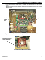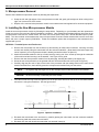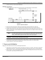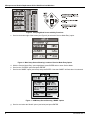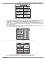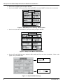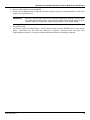
1
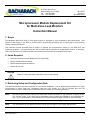
621 Hunt Valley Circle New Kensington, PA 15068 Tel: 724-334-5000 Fax: 724-334-5001 3015-5547 Revision 3 December 2012 Microprocessor Module Replacement Kit for Multi-Zone Leak Monitors Instruction Manual 1. Scope The Bacharach Multi-Zone family of fixed point monitors is designed for easy maintenance and enhancement. One element of that design is the ability to replace system programming (firmware) with a simple plug-in microprocessor module, minimizing downtime. This instruction manual describes how to replace or upgrade the microprocessor module in your Multi-Zone leak monitoring equipment. It is assumed that the user is familiar with the operation of the appropriate monitor. If necessary, refer to the instructions for detailed operation and maintenance information for each Multi-Zone model. 2. Items Required Replacement Microprocessor Module Kit (P/N: 3015-5546) Medium Phillips head screwdriver Medium standard slotted screwdriver Wrench for lock nut CAUTION Failure to comply with these instructions may void the warranty. 3. Retrieving Setup and Configuration Data Your Multi-Zone monitor has been configured for your specific installation. Prior to beginning this procedure it is highly recommended to collect setup and configuration data from your monitor so it can be reloaded after the new microprocessor module is installed. Use the table that follows to record the necessary parameters. NOTE: Note that a system hardware failure may make these values inaccessible or may reset them to default values in a “fail safe” mode. If the values are not accessible or do not match your installation, you should skip this step. If you need assistance, contact Bacharach Technical Support at (800) 736-4666 or (724) 334-5000. NOTE: The node address of your Multi-Zone device can be found on page 2 of the System Setup Screen. 3015-5547 Rev 3 1 Microprocessor Module Replacement Kit for Multi-Zone Leak Monitors NODE ADDRESS = _________ ZONE LOCATION (From screen) (Based on your physical installation) NUMBER OF ZONES = __________ GAS LENGTH OF TUBING TEMP AT ZONE STORED ALARM LEVELS LEAK LEVEL SPILL LEVEL EVAC LEVEL 1 2 3 4 5 6 7 8 9 10 11 12 13 14 15 16 4. Removal Preparation Prepare to remove the old microprocessor module by following the steps below. a. Disconnect power to the leak monitor and confirm that no power is present. WARNING Failure to remove power can cause damage to the monitor and can cause personal injury or death. b. Remove the two screws on the left edge of the front panel. c. Open the front panel and ground your body by touching an area of bare metal. WARNING Failure to touch the grounding area can allow static electricity on your clothing or body to damage the monitor or modules. Such damage is not covered under warranty. d. Disconnect the 12-position screw terminal to prevent activating alarm equipment. 2 3015-5547 Rev 3 Microprocessor Module Replacement Kit for Multi-Zone Leak Monitors e. Locate the microprocessor module, socketed on the bottom right side of the main circuit board. Refer to Figure 1. f. Note the orientation of the module, specifically the gold tab and hole oriented on the bottom left of the board. Refer to Figure 2. Microprocessor Module 12-position Screw Terminal Block Figure 1. Locations of Terminal Block and Microprocessor Module Inside the Multi-zone Cabinet Note Position of Gold Tab and Hole (Bottom Left) Figure 2. Orientation of Microprocessor Module 3015-5547 Rev 3 3 Microprocessor Module Replacement Kit for Multi-Zone Leak Monitors 5. Microprocessor Removal Remove the installed microprocessor module by following the steps below. a. Grasp the left and right edges of the microprocessor module and gently pull straight out while rocking left to right, until it comes free of the socket. b. Dispose of the removed microprocessor module in accordance with local regulations for electronic equipment. 6. Installing the New Microprocessor Module Install the new microprocessor module by following the steps below. Depending on your hardware and the replacement kit that you receive, there are two different installation procedures. One method accommodates different hole sizes in the microprocessor board and the mother board, and uses two screws (0001-1552) and a female-threaded spacer (03048289). The other method accommodates the newer microprocessor board and mother board which have the same size holes, and uses a snap-in spacer (0304-8459). Follow the installation option that corresponds to the hardware that is supplied with your kit. OPTION A: Threaded Spacer and Two Screws a. Remove the main board from the enclosure by disconnecting all main board connectors, removing mounting screws, and carefully lifting the main board from the enclosure standoffs. (Note that this and other steps may not be required if your microprocessor board is already mounted as shown in Option A.) b. Attach the threaded standoff to the top of main board by routing one of the screws up through the underside of the main board and securing it to the standoff. Use Figure 3 as a guide. c. Remove the new microprocessor module from its packaging, handling the board by the edges only. d. Orient the new microprocessor so the gold tab and hole are at the bottom left corner (refer to Figure 2). e. Carefully align the two rows of pins on the back of the processor with the mating socket on the main circuit board in the Multi-Zone, then carefully press the microprocessor module firmly into the socket. NOTE CAUTION f. As a guide, align the larger hole on the microprocessor module with hole in the standoff. Be sure not to skip or offset the pins to the socket. Feed the second securing screw through the hole in the processor board into the top of the threaded standoff and secure it using the screwdriver. See the figure below. Figure 3. Option A Installation g. Re-attach the main board to the enclosure by carefully placing the main board onto the enclosure standoffs and securing it with the screws removed earlier. h. Re-attach only the main board connectors that you removed in step (a). 4 3015-5547 Rev 3 Microprocessor Module Replacement Kit for Multi-Zone Leak Monitors i. Continue with Step 7: Power-up and Initialization. OPTION B: Snap-in Spacer a. Insert the plastic snap-in spacer into the securing hole on the mother board. See figure below. Figure 4. Option B Installation b. Remove the new microprocessor module from its packaging, handle the board by the edges only. c. Orient the new microprocessor so the gold tab and hole are at the bottom left corner (refer to Figure 2). d. Carefully align the two rows of pins on the back of the processor with the mating socket on the main circuit board of the Multi-Zone, while simultaneously aligning the snap tab on the spacer with the hole in the microprocessor board. NOTE CAUTION As a guide, align the larger hole on the microprocessor module with the top of the snap-in spacer. If aligned properly, the pins will align with the main board socket and the hole in the microprocessor board will align with the top connector of the snap-in spacer. Be sure not to skip or offset the pins to the socket. e. Ensuring that the pins are properly aligned and the snap-in spacer is in place and properly aligned, press the microprocessor module firmly into the socket while simultaneously securing it to the snap-in spacer. j. Continue with Step 7: Power-up and Initialization. 7. Power-up and Initialization Apply power and initialize the leak monitor by following the steps below. a. Apply power to the leak monitor and wait for the power-up sequence to complete. Note that the yellow fault light may flash at this time. The green power LED will flash to indicate that the monitor is in Warm Up Mode. b. With the monitor in either Warm Up Mode (flashing green LED) or Sampling Mode (solid green LED), access the Setup Menu by pressing the ENTER key twice. 3015-5547 Rev 3 5 Microprocessor Module Replacement Kit for Multi-Zone Leak Monitors Figure 5. Sampling Mode Screen with Key Functions c. Scroll to the bottom right of the screen (see Figure 6) to select the ‘Service Mode Entry’ option. Figure 6. Main Setup Screen Showing Location of Service Mode Entry Option d. With the ‘Service Mode Entry’ option highlighted, press ENTER twice to enter Service Mode. e. Scroll to the “SYSTEM” option and press ENTER. f. Scroll to the “MORE” option (see below) and press ENTER. Note that “MORE” will flash when it is selected. Figure 7. HGM Setup Screen Showing “MORE” Option g. Scroll to and select the “Model” option (see below) and press ENTER. 6 3015-5547 Rev 3 Microprocessor Module Replacement Kit for Multi-Zone Leak Monitors Figure 8. Setup Screen When in Service Mode h. Use the UP and DOWN arrow keys to select the model type of your monitor from the scrolling list (for example, REF for refrigerant). With the proper model selected, press ENTER to save that change. i. Press ESC to get to the System Menu. Scroll to IN SERVICE QUIT and press ENTER twice to leave Service Mode. Press ESC once and allow the instrument to complete a pressure check and purge cycle (approximately 2 minutes). j. With the monitor in either Warm Up Mode (flashing green LED) or Sampling Mode (solid green LED), access the Setup Menu by pressing the ENTER key twice. Figure 9. Sampling Mode Screen k. Scroll to the bottom right of the screen (see Figure 8) to select ‘Service Mode Entry’. Figure 10. Main Setup Screen Showing Location of Service Mode Entry Option l. With ‘Service Mode Entry’ highlighted, press ENTER twice to enter Service Mode. 3015-5547 Rev 3 7 Microprocessor Module Replacement Kit for Multi-Zone Leak Monitors m. Scroll to the “SYSTEM” option and press ENTER. n. Scroll to the “MORE” option (see below) and press ENTER. Note that “MORE” will flash when it is selected. Figure 11. HGM Setup Screen Showing “MORE” Option o. Scroll to and select the “IR DIGIPOT” option (see below) and press ENTER. Figure 12. Setup Screen When in Service Mode p. Use the UP and DOWN arrows to adjust the MW reading to 450 (or as close as possible). When at the proper value, press ESC once. DIGIPOT= 180 IR VOLT= 4.21 V= 4.7 R= 49 MA= 96 MW= 450 Figure 13. Sample DIGIPOT Readings 8 3015-5547 Rev 3 Microprocessor Module Replacement Kit for Multi-Zone Leak Monitors q. Scroll to ‘DET DIGIPOT’ and press ENTER. r. Use the UP and DOWN arrows to adjust the IR VOLT reading to 4.20 (or as close as possible). When at the proper value, press ESC once. IMPORTANT! s. t. If IR VOLT does not reach 4.200 ±0.100 volts when adjusting the DIGIPOT, return to step (n) to lower the IR emitter setting. If the IR emitter setting is 450 ±20 mW, adjust the new IR emitter setting to 375 ±20 mW. Repeat step (p) with the new IR emitter setting. Press ESC to save. Press ESC to get to the System Menu. Scroll to Service Mode and press ENTER twice to leave Service Mode. Press ESC once and allow the instrument to complete a pressure check and purge cycle (approximately 2 minutes). If there are no faults the IR bench has been successfully configured. 3015-5547 Rev 3 9 Microprocessor Module Replacement Kit for Multi-Zone Leak Monitors 8. Reload Setup Parameters Reload the previously saved setup parameters and configuration data by following the steps below. a. With the monitor in either Warm Up Mode (flashing green LED) or Sampling Mode (solid green LED), access the Setup Menu by pressing the ENTER key twice. Figure 14. Sampling Mode Screen b. Scroll to the “SYSTEM” option and press ENTER. Figure 15. Main Setup Screen c. Use the UP and DOWN arrow keys to select the LOCATION setting and press ENTER. (Note: This is the location of the Multi-Zone unit, and NOT the location of the individual zones.) Use the LEFT and RIGHT arrow keys to select the letter to be changed, and use the UP and DOWN arrow keys to choose the new letter or number for that position. Press ENTER to save the changes, or ESC to abort the changes. Figure 16. HGM Setup Screens 10 3015-5547 Rev 3 Microprocessor Module Replacement Kit for Multi-Zone Leak Monitors d. Use the UP and DOWN arrow keys to select the NUM ZONES INSTALLED setting and press ENTER. e. Use the UP and DOWN arrow keys to choose the number of physical zones (solenoids) installed in your Multi-Zone (i.e., 4, 8, 12, or 16 zones). Press ENTER to save the changes, or ESC to abort the changes. NOTE f. The NUM ZONES INSTALLED setting defines the maximum number of zones that your Multi-Zone is capable of measuring (i.e., a hardware parameter), NOT the number of zones defined by your application. For example, your Multi-Zone may be equipped with 16 hardware solenoids (zones), but your application uses only 13 of those zones. In this case, NUM ZONES INSTALLED is set to 16. You must set the tubing length to 0 ft for the other 3 unused zones. Using steps (c) through (e) as guides, change the other system settings as required. The other system settings are: • ALM ACK MODE • REZERO MODE • AUDIBLEALARM • RS485 BAUD • ZONE HOLD • NODE ADDRESS • DETECTION LIMIT • PASSWORD. • LOOP2 FACTOR g. When all changes are complete, press ESC to return to the Main Setup Screen. Figure 17. Main Setup Screen h. Use the DOWN arrow key to select the ZONES setting and press ENTER. There is a Setup Menu for each zone specified by the NUM ZONES INSTALLED setting set previously. Figure 18. Zone #1 Setup Screens 3015-5547 Rev 3 11 Microprocessor Module Replacement Kit for Multi-Zone Leak Monitors i. j. Use the LEFT and RIGHT arrow keys to scroll through all Zone Setup Screens. Select and change the zone settings as required or as recorded earlier in the table on page 2. The zone settings are: • LOCATION • LOG INTERVAL • REFRIGERANT • LEAK LEVEL • DISTANCE (length of tubing) • SPILL LEVEL • TEMP AT ZONE • EVAC LEVEL. k. When all changes are complete, press ESC to return to the Main Setup Screen. l. Press ESC to return to the Main Run Screen. m. After configuring all parameters, press the CPU reset button on the bottom edge at the center of the main circuit board (refer to Figure 19). The monitor will restart and enter the warm-up state. CPU Reset Button Figure 19. Location of CPU Reset Button n. Confirm that there are no faults indicated, and reconnect the 12-position screw terminal. o. Close the front panel and reinstall the panel screws. ∇ ∇ ∇ Headquarters: 621 Hunt Valley Circle, New Kensington, PA 15068-7074 Toll Free: 1-800-736-4666 • Tel: +1-724-334-5000 • Fax: +1-724-334-5001 Website: www.MyBacharach.com • E-mail: [email protected] Printed in U.S.A. 12 ® Registered Trademark of Bacharach Inc. 3015-5547 Rev 3