1
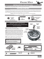
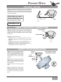
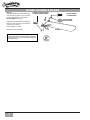
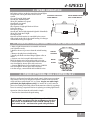
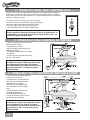
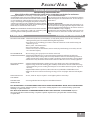
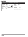
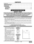
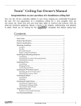
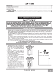
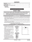
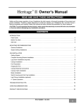
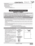
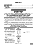
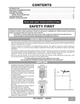
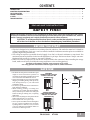
CONTENTS
INTRODUCTION . . . . . . . . . . . . . . . . . . . . . . . . . . . . . . . . . . . . . . . . . . . . . . . . . . . . . . . . . . . . . . . . . . . . . .
mounting recommendations . . . . . . . . . . . . . . . . . . . . . . . . . . . . . . . . . . . . . . . . . . . . . . . . . . . . . . . . . .
fan INSTALLATION . . . . . . . . . . . . . . . . . . . . . . . . . . . . . . . . . . . . . . . . . . . . . . . . . . . . . . . . . . . . . . . . . . .
control features:
4 Speed. . . . . . . . . . . . . . . . . . . . . . . . . . . . . . . . . . . . . . . . . . . . . . . . . . . . . . . . . . . . . . . . . . . . . . . . . . . .
troubleshooting . . . . . . . . . . . . . . . . . . . . . . . . . . . . . . . . . . . . . . . . . . . . . . . . . . . . . . . . . . . . . . . . . . .
1
2
3
6
9
READ AND SAVE THESE INSTRUCTIONS
SAFETY FIRST
Safety and the proper operation of your Casablanca fan both require a thorough knowledge of the product
and proper installation; therefore, before attempting to install and operate your Casablanca fan, read this
owner’s manual completely and carefully. Retain this manual for future reference.
CAUTION: To avoid possible electrical shock, make certain that electricity is turned
off at the circuit breaker or fuse box before attempting any installation procedure.
BEFORE YOU START
• This fan is designed to be installed on an existing electrical outlet box. The outlet box must be UL Listed for
ceiling fan installations, if it is not, a new box must be installed. Casablanca extension poles are available for
sloped or high ceiling installations.
• This ceiling fan requires a grounded electrical supply of 120 VAC, 60 Hz and a minimum 15 amp circuit. The
maximum current requirement for the fan with light fixture is 3.8 amps. The fan uses about 1 amp or 100 watts.
Maximum light current is 2.8 amps or 340 watts of lighting.
• Where wire nuts are employed, be sure all bare wires are within the connectors. When installing the canopy
hatch, make sure all wires are within the canopy and that no wires are being pinched.
For best performance and for your warranty to be valid,
use only genuine Casablanca blades, light fixtures, and accessories.
SAFE USE
• The blades in each pack are matched for equal
weight to assure smooth fan operation. If
more than one fan is being installed, be careful
not to mix blades from different cartons.
• Inspect the contents of your carton for possible
shipping or handling damage and report any
such damage directly to your authorized
Casablanca dealer.
• It is always a good idea to have an assistant to
help with the installation.
• When cleaning, painting, or working near
your fan, be very careful of the fan and blades.
Always turn the power OFF to the ceiling fan
before servicing it, working on it, or replacing
light bulbs.
• Never insert anything into the path of the fan
blades while the fan is in operation.
• Never install a fan over a pool or spa.
• Never operate a fan that has been damaged in
any way. Contact Casablanca Fan Company
by calling toll free 1-888-227-2178, or contact
your local authorized Casablanca dealer for
assistance in obtaining service.
FUSE BOX
(Remove fuse for the
circuit you will be
working on)
18”
70”
84”
CIRCUIT BREAKER
(Trip breaker for the
circuit you will be
working on)
PN 6643040
AT1108
1
MOUNTING RECOMMENDATIONS
Before mounting your Casablanca fan, read the following helpful recommendations. The location of the fan, air
circulation, and fan size are all important factors to consider before installation.
Location
Ceiling fans have practical uses in almost every room in your home. We suggest you follow these mounting
recommendations as you decide where to install your Casablanca fan.
• For safety reasons, the fan blades must be a minimum of 7’ above the floor.
• Do not locate the fan in a doorway or above a swinging door.
• In any installation, the tips of the blades must be at least 18” from the wall in order
to provide sufficient clearance for the blades.
• In bedrooms, fans work best when mounted above the foot of the bed.
• Over pool tables, be sure to provide plenty of clearance to avoid
damage from pool cues.
• In kitchens be sure to allow for open cupboard doors to clear the fan
blades.
• Do not install a fan close to, or over, a pool or spa. High humidity
combined with corrosive gases will destroy the finish and warp the
blades.
Fan Size
Variable fan speed capability permits the use of a full-size 52” fan even in
smaller rooms. For very large rooms, two fans may be needed.
SLOPED CEILING INSTALLATIONS
Suggested Extension Pole
Pole Length
Ceiling Height
Standard
8”
Standard
8’ 6”
6”
9”
12”
9’ 6”
12”
10”
18”
11”
24”
12”
36”
13”
48”
14”
When to Use Extension Poles
For best performance and best appearance,
an extension pole should be used with your
Casablanca fan when installing on high
(cathedral) ceilings or sloped ceilings. Casablanca offers standard poles in increments
of 6″ up to 5″. Custom poles are available
in lengths up to 9′9″. See your Authorized
Casablanca Dealer for details.
Note: Fan may wobble or
vibrate if pole length is not
long enough and inside blade is
too close to downslope or side
wall. Extending pole length will
usually solve problem.
Calculation of 32°
Use the tear-off Ceiling Angle Template card inserted
in the back of this manual, it provides you with a
simple ‘go’ or ‘no-go’ for installing your fan on a sloped
ceiling.
2
maximum
angle 32º
Extension
Pole
blades must be
a minimum of 7’
above the floor
7’ minimum
EXAMPLE 1
This slope is less than 32°.
It is OK to install your fan.
EXAMPLE 2
This slope is 32°. This is the maximum
slope that will allow the fan to hang
straight down. It is OK to install
your fan.
EXAMPLE 3
This slope is more than 32°.
Your fan will not hang straight down,
an adaptor is necessary. Contact your
local Authorized Casablanca Dealer in
regards to purchasing a “Slope Ceiling
Adaptor.”
Panama® Halo
INSTALLATION INSTRUCTIONS
Unpacking: Before assembling and installing your ceiling fan, remove all parts from the shipping cartons and check them against the parts
listed here. Before discarding packaging material, be certain that all parts have been removed.
getting started
Carton Contents
The fan carton contains the fan body, warranty card, owner’s manual, and all the parts neccessary ( except blades) to assemble and install
your Casablanca ceiling fan. These parts are shown at the start of each installation section. before you start, go through thie Owner’s manulas
and confirm thaat you have all the parts shown in each section. Be Sure to use only genuine Casablanca blades, The blade shrink wrap holds 5
blades of matched weight. If more than one fan is being installed, be sure not to mix blade sets
Caution: When removing the shrink wrap, be careful not to scratch the blades.
perma•lock™ hardware
ALLEN SET
SCREW
1 4
¦ -20 x 1¦4”
(pre-installed)
downrod & Ball
assembly
3mm
allen wrench
Fan preparation
important safety information!
motor
wires
before starting the installation of your ceiling fan,
install the threaded downrod into the motor coupling
and lock the assembly
Prepare for fan installation as follows:
Step A. Route the wires from the motor through the
Perma•Lock™ downrod and ball assembly.
Tip: The downrod has a tapered thread that is designed to lock completely when correctly installed.
Step B. Using the provided allen wrench, loosen the set
screw several turns to allow installation of the downrod.
Thread the downrod into the motor coupling until it stops
turning, this will take at least four and a half full turns.
ground
wire
downrod
& Ball
assembly
tapered
thread
ALLEN
SET SCREW
Step C. Securely tighten the set screw with the provided
allen wrench to ensure safe operation of your fan.
CAUTION: Failure to fully lock in the downrod before securely tightening the set screw
may cause the fan to separate from the
downrod during normal operation!
motor
coupling
CEILING HARDWARE
additional hardware
CROSSBAR
MOUNTING
BRACKET
WIRE NUT (4)
2 1/4” x 8-32 round
head screws (2)
FLAT WASHER
1” x 8-32 round
(2)
head screws (2)
support installation
Lag screw
3/8”7 x 5”
large flat
washer 3/8”
3
Crossbar Mounting Bracket INSTALLATION
Note: After removing the old fixture, check the outlet
box to insure that it is supported by a joist or beam
across its upper surface. If not, a 2” x 4” stud must
be installed.
Step 1. Remove the knockout plug in the center of the
outlet box or drill a 1/2” hole for the lag screw to pass
through. Then drill a 1/4” guide hole into the joist or beam
to a depth of 3”.
Step 2.Route the outlet box wires through the keyhole
slot of the crossbar mounting bracket as shown. Attach the
crossbar mounting bracket to outlet box with screws provided, assuring that the outlet box wires are not pinched
by the washer.
CAUTION: To reduce the risk of personal
injury, use only the mounting hardware provided with the approved outlet box to install
the crossbar mounting bracket.
JOIST
ceiling
wiring
ceiling fan
approved
wiring box
ridge side
down
crossbar
mounting
bracket
flat
washer
green ground
wire
approved outlet
box hardware
WARNING!
SUPPORT DIRECTLY TO
BUILDING STRUCTURE ONLY.
LAG SCREW INSTALLATION
Step 3. With the large washer attached, pass the lag
screw through the center hole of the crosbar mounting
bracket and screw into guide hole. Tighten until outlet
box is firmly mounted to beam. This box must be firmly
secured to the ceiling. We recommend that the ceiling
fixture outlet box be of sufficient capacity enabling it
to support the weight of fan and light fixture under any
conditions.
lag
screw
LARGE
WASHER
CANOPY HARDWARE
CANOPY SCREW (4)
CANOPY
HATCH
4
CANOPY
CANOPY LOCK WASHER
(4)
Panama® Halo
HANGING THE FAN
Step 4. To hang the fan body in the canopy, hold the fan
body firmly and insert the ball into the canopy opening.
Check that no wires were pinched. Rotate the fan body
until the slot in the nylon ball fits into the pin opposite
the canopy opening.
ball
Note: Independent control of
the light fixture using a W-81 requires an additional power wire
run from the wall switch to the
fan. See Page 10 for wiring.
slot
pin
Fan Weighs 27 lbs
CANOPY ELECTRICAL CONNECTIONS
Step 4a. Attach the fan wires to the ceiling fixture
outlet box wiring by twisting the bare ends of the wires
together and then securing with a wire nut. Test that the
connection is secure by pulling on the wire nut. Conect
in this order:
Step 4b. Wiring Connections
• GREEN leads from mounting plate and fan to
GROUND conductor of power source. Secure with
wire nut.
• WHITE wire from fan to white NEUTRAL wire in
ceiling fixture outlet box. Secure with wire nut.
• BLACK power wire from fan to BLACK power wire in
ceiling outlet box. Secure with wire nut.
2 BLACK WIRES
2 WHITE WIRES
3 GREEN
WIRES
CANOPY HATCH INSTALLATION
Step 5. Tuck the wires into the canopy
with the wire nuts pointed upwards,
so that the WHITE and BLACK wires
are on opposite sides of the canopy
and all wires are clear of the canopy
opening.
Step 6. Install canopy hatch with the
last canopy screw and lock washer. To
do this, tilt the fan body away from the
hatch opening.
Tighten the screws firmly by hand
only,
canopy
hatch
tilt the fan to install
last canopy screw
lock
washer
canopy
screw
Step 7. Straighten the fan, then check
to ensure that there is no movement
between the canopy and ceiling
or Hang-Tru ball and top support
shaft.
5
blade holder & BLADE
Step 8.
Attach the blades to the blade holders
with the three blade screws and felt
washers provided for each blade.
Hand tighten securely.
BLADE HOLDER SCREW
(2 PER BLADE HOLDER)
BLADE SCREW
(3 PER BLADE)
felt washer
(3 PER BLADE)
Install the assembled blade and blade
holder to the flywheel (round holes)
or direct drive motor.
Hand tighten securely.
Repeat for each assembly.
WARNING: To reduce the risk of personal injury, do
not bend blade holders when installing, balancing,
or cleaning. Do not insert foreign objects between
rotating fan blades.
6
BLADE
4 - speed operation
4-SPEED
Pull-chain switches on the fan control the fan and lights.
Using the fan control pull-chain switch: Fan off
Fan & speed control
Optional light pull
at start.
pull chain switch
Chain switch
First pull: fan ON, High speed
Second pull: Medium speed
Third pull: Medium Low speed
Fourth pull: Low speed
Fifth pull: Fan OFF
The sequence of Light pull chain as follows:
Light off at Start
First pull: Up Light
Second pull: Down Light (Optional Light Kit If Installed)
Third pull: Up & Down Light
reverse
Fourth pull: Off
Direction of blade rotation is controlled by the reverse
slide switch on the side of the switch housing. No changes
in household wiring are required.
4 - speed optional Light Fixture installation
1. Refer to light kit instructions to assemble and attach
your light kit correctly.
2. Remove the two 8-32 screws from the switch housing
cap.
3. Remove the plug from switch housing.
4. Install pull-chain switch and Finger tighten collar on
switch.
5. Connect one wire from pull-chain switch to the
BLUE D1-Option wire. Secure splice with a wire nut.
6. Connect other wire from pull-chain switch to BLACK
wire from light kit. Secure splice with a wire nut.
7. Connect WHITE wire from switch housing to WHITE
wire from light kit. Secure splice with a wire nut.
8. At the canopy, connect the BLACK and BLUE wires.
switch
housing
collar
Blue d-1
white
black
light fixture
4 - speed optional Wall Control w-41
The W-41 wall control provides four-speed control of fan from a convenient
wall location. The W-41 is designed to replace a standard wall switch and
will fit wall boxes with a depth of 2” or greater. Not for use with single
pull-chain fan/light option wiring. To install a W-41 wall control in
place of an existing wall switch, follow the instructions on the W-41 package.
Note: No rewiring is required if the fan is replacing an existing light Fixture.
Operation of the fan from the wall switch is simple:
1. Turn knob to obtain desired speed setting.
CAUTION! Failure to set the pull-chain speed to HIGH can
result in faulty operation of the fan and damage to the W-41
wall control. To confirm fan is set to HIGH: TurnW-41 fan
speed switch to ‘HI’ - set fastest fan speed with pull chain.
7
4 - speed optional wall control W-81
The W-81 wall control provides separate control of fan and light with two separate
knobs from a convenient wall location. The W-81 is designed to replace a standard
wall switch and wall boxes with a depth of 2” or greater. Requires two hot leads from
wall box to ceiling wiring box.
MED
To install a W-81 wall control in place of an existing
wall switch, follow the instructions on the W-81 package.
Operation of the fan from the wall switch is simple:
1. Turn the upper knob to the desired fan speed.
2. Turn the lower knob to the desired light setting.
LO
OFF
OFF
MED
HI
HI
MAX
CAUTION! Failure to set the pull-chain speed to HIGH can result in
faulty operation of the fan and damage to the W-81 wall control. To
confirm fan is set to HIGH: TurnW-81 fan speed switch to ‘HI’ - set
fastest fan speed with pull chain.
4 - speed W-41 wall control of the fan
• The W-41 allows the choice of four (4)
different speed settings.
• No light fixture is used.
• Set the FAN pull chain switch to the
HIGH speed setting.
• No changes in household or fan wiring
are required.
• The fan may be turned ON and OFF by
the W-41 wall control.
CAUTION! Failure to set the pull-chain speed
to HIGH can result in faulty operation of the
fan and damage to the W-41 wall control. To confirm fan is set to HIGH: TurnW-41 fan
speed switch to ‘HI’ - set fastest fan speed
with pull chain.
R
4 - speed W-81 Wall control of the fan & light
• The fan may be turned ON and OFF
by the W-81 wall control.
• The lights may be turned ON and
OFF by the W-81 and the intensity
adjusted from low to high.
• The fan must be supplied with
two independent 120V AC supply
wires.
• Set the FAN pull chain switch to
the HIGH speed setting.
• Turn the lights ON at the fan.
• The W-81 allows the choice of four
(4) different speed settings.
CAUTION! Failure to set the pull-chain speed
to HIGH can result in faulty operation of the
fan and damage to the W-81 wall control. To confirm fan is set to HIGH: TurnW-81 fan
speed switch to ‘HI’ - set fastest fan speed
with pull chain.
8
Panama® Halo
Troubleshooting
Before Requesting Service:
Please follow this troubleshooting guide before contacting your dealer for assistance.
Caring for Finishes: For cleaning, a soft brush or lint-free
cloth should be used to prevent scratching the finish. A vacuum
cleaner brush nozzle can remove heavier dust. Surface smudges
or an accumulation of dirt and dust can easily be removed by
using a mild detergent and slightly dampened soft cloth. An
antistatic agent may be used, but never use abrasive cleaning
agents. These will damage the finish. Painted and high-gloss
blades may be cleaned in the same manner.
Blades: Wood finish blades should be cleaned with a furniture
polishing cloth. Occasionally, a light coat of furniture polish
may be applied for added protection and beauty.
Never Lubricate this Fan!
The precision motor at the heart of your Airflow fan features
sealed bearings that are lubricated for life. Do not attempt to
oil the motor.
Changing Light Bulbs
Be sure to turn power to the fan OFF at the wall switch or circuit breaker before changing light bulbs. Replace bulbs with
same type as removed from the fixture. Each fan is rated for a
maximum TOTAL wattage of lighting.
Exceeding the rated maximum allowable wattage for the fan
will burn out the fan electronics module and void the warranty.
Problempossible remedies..
FAN WILL NOT START •Check main circuit fuses, circuit breakers, or wall switch position. Check all wire connections,
making sure the power is turned off during this inspection.
•Pin connectors are not making good contact. Check the connections in the switch housing and
under the top cover.
•Battery weak - install fresh battery.
•Fan receiver defective - replace.
•Check receiver (fan) and transmitter (remote control) dip switch settings to see if they are both
set to the same frquency.
FAN WOBBLES OR •Be sure canopy pin is properly set into the slot on the ball.
SHAKES EXCESSIVELY •Check that bladeholders have not been bent during installation and blades are balanced.
•Hanger bracket and/or ceiling outlet are loosely attached: Make sure that the hanger bracket is
tightly attached to the ceiling outlet box. Make sure that the downrod assembly is secured firmly
•Downrod is loosely attached to downrod base: Make sure that all screws are securely tightened
FAN NOISY DURING
OPERATION
•Check and tighten light fixture retaining screws, glass shade screws and/or the light bulb(s).
•Tighten canopy screws and mounting plate assembly. Check that the wire nuts inside the canopy
and switch housing are not touching the metal parts or have fallen off the wire splices. Tighten as
necessary.
•Tighten blade holders to flywheel (or direct drive motor)/and blade to bladeholder screws.
•Make sure all screws in the motor housing are snug, but not overly tight. Defective bulb: Replace
bulb.
DOES NOT RUN ON
LOW SPEED
•If new, “break-in” may be required - run at higher speed for several days.
BATTERY LIFE
SEEMS SHORT •Not using Alkaline batteries: Replace with Alkaline batteries.
FAN RUNS SLOWLY IN EITHER DIRECTION IF ROTATION IS STARTED BY HAND; WILL NOT REVERSE:
Defective reverse switch; defective capacitor; or open motor winding: Replace reverse switch assembly; replace PCB
assembly; or replace motor unit.
FAN WILL NOT OPERATE AT PROPER SPEEDS OR WILL NOT OPERATE AT ANY SPEED: Defective
three-speed pull-chain switch assembly; or defective capacitor: Replace three-speed pull-chain switch assembly;
or replace PCB
9
Product Specifications
Model Name:
Model Number:
Panama® Halo
66HXXF
Dimensions:
NOTE: Dimension B
light fixture
includes
and glass.
A =10.75"
B =12.46"
C = 3"
D =13.43"
E =5.6"
Weight:
10
27 lbs.
Motor:
Blade Span:
Blade Iron Pitch:
No. of Blades:
Technology:
XTR200® x 20mm
42" or 50"
20°
5
4-Speed
Airflow*:
Electricity Use*:
Airflow Efficiency*:
6,480 cfm
84 watts
73 cfm/watt
* Performance data is for fan only. No lighting wattage is included.
Measurements taken with 21" basic blades.